JP2017126187A - Meter reading device - Google Patents
Meter reading device Download PDFInfo
- Publication number
- JP2017126187A JP2017126187A JP2016004946A JP2016004946A JP2017126187A JP 2017126187 A JP2017126187 A JP 2017126187A JP 2016004946 A JP2016004946 A JP 2016004946A JP 2016004946 A JP2016004946 A JP 2016004946A JP 2017126187 A JP2017126187 A JP 2017126187A
- Authority
- JP
- Japan
- Prior art keywords
- meter
- rotation angle
- image
- pointer
- angle
- Prior art date
- Legal status (The legal status is an assumption and is not a legal conclusion. Google has not performed a legal analysis and makes no representation as to the accuracy of the status listed.)
- Pending
Links
Images


Abstract
Description
本発明は、電力設備などの盤に取り付けたメータを自動で読み取る装置に関し、特にメータをカメラで撮影した画像を処理することでメータの目盛を読み取るメータ読取装置に関する。 The present invention relates to a device that automatically reads a meter attached to a panel such as a power facility, and more particularly to a meter reading device that reads a scale of a meter by processing an image obtained by photographing the meter with a camera.
従来、カメラで撮影した画像を処理することでメータの目盛を読み取る方法が提案されている(例えば、下記特許文献1〜4参照)。
Conventionally, a method of reading a scale of a meter by processing an image photographed by a camera has been proposed (for example, see
特許文献1には、指針の稼動領域の画像を、指針回転中心を基準として極座標変換した画像を作り、予め用意しておいた極座標変換した基準画像を用いて極座標変換した入力画像の位置ずれを補正した後、指針の回転角度をもとに指示値を求める構成が記載されている。
In
特許文献2には、指針式メータの指針の稼動領域に対して指針回転中心から指定した距離にある円周上に仮想線を設定し、仮想線に対応する一次元データの輝度変化を基に指針の指示値を求める構成が記載されている。
In
特許文献3には、指針の輝度値を予め設定しておき、入力画像中から指針の輝度値に近い輝度値を持つ領域を塊として抽出し、その塊を楕円に近似して楕円の軸方向から指針の差す値を求める構成が記載されている。
In
特許文献4には、指針が一定間隔で回転した場合の画像を指針パターンとして作成し、その指針パターンと入力画像とのパターンマッチングを行うことで指針の指示値を読み取る構成が記載されている。
しかしながら、特許文献1の方法では、画像を極座標変換した画像を作り、極座標変換した基準画像と入力画像との照合を行うため大きなメモリ操作が必要となり、また複雑な計算が必要であるという問題があった。
However, the method of
また、特許文献2の方法では、一次元データのみで指針の状態を調査するため簡単な処理で指針の指示値を求めることができるが、一次元データしか見ていないので、ノイズに弱く誤計測が発生しやすいという問題があった。
Further, in the method of
また、特許文献3の方法では、輝度値を基に指針部分を探索するため輝度変化への対応が難しく、この方法を適用できる場所は屋内の輝度変化のない場所に限られるという問題があった。
In addition, the method of
また、特許文献4の方法では、メータ検出に多くのパターンを必要とするため、予めパターンを作っておく場合はパターンを保存しておく大きなメモリが必要となる。また、メータ読取を行う都度にパターンを作成する場合は、パターン作成のための処理時間を要するという問題があった。
In addition, since the method disclosed in
このようなことから本発明は、簡単な処理でノイズに強く高精度にメータの読み取りを行うことが可能なメータ読取装置を提供することを目的とする。 In view of the above, an object of the present invention is to provide a meter reader capable of reading a meter with high accuracy against noise with a simple process.
上記の課題を解決するための第1の発明に係るメータ読取装置は、
カメラによって撮影したメータの画像から前記メータの目盛値を読み取るメータ読取装置において、
前記メータの画像を二値化した画像データを作成する二値化処理部と、
前記二値化した画像データから黒点を探索し、前記黒点の分布をメータ座標系に変換してなる回転角度ヒストグラムを作成する回転角度ヒストグラム作成部と、
前記回転角度ヒストグラムの黒点数が最大となる角度を指針回転角度として検出する回転角度検出部と、
前記指針回転角度からメータ目盛値を算出するメータ目盛値計算部と
を備えることを特徴とする。
The meter reader according to the first invention for solving the above-mentioned problems is
In the meter reading device that reads the scale value of the meter from the image of the meter photographed by the camera,
A binarization processing unit for creating image data obtained by binarizing the image of the meter;
A rotation angle histogram creating unit that searches for black spots from the binarized image data and creates a rotation angle histogram formed by converting the distribution of the black spots into a meter coordinate system;
A rotation angle detector that detects an angle at which the number of black spots in the rotation angle histogram is maximum as a pointer rotation angle;
And a meter scale value calculator for calculating a meter scale value from the pointer rotation angle.
また、上記の課題を解決するための第2の発明に係るメータ読取装置は、
前記回転角度検出部が、前記回転角度ヒストグラムの黒点数を二次曲線で補間して当該二次曲線のピーク位置を指針回転角度として検出する
ことを特徴とする。
Moreover, the meter reader according to the second invention for solving the above-mentioned problem is
The rotation angle detector may detect the peak position of the quadratic curve as a pointer rotation angle by interpolating the number of black spots in the rotation angle histogram with a quadratic curve.
また、上記の課題を解決するための第3の発明に係るメータ読取装置は、
前記回転角度検出部が、黒点数が最大となる角度の前後において黒点数が予め設定する値以上となる角度を求め、当該黒点数が前記予め設定する値以上となる角度の範囲が所定の角度範囲以下である場合に前記黒点数が最大となる角度を指針回転角度として出力する
ことを特徴とする。
A meter reader according to a third invention for solving the above-described problem is
The rotation angle detection unit obtains an angle at which the number of black spots is equal to or greater than a preset value before and after the angle at which the number of black spots is maximum, and a range of angles where the number of black spots is equal to or greater than the preset value is a predetermined angle The angle at which the number of sunspots is the maximum when it is below the range is output as the pointer rotation angle.
また、上記の課題を解決するための第4の発明に係るメータ読取装置は、
前記回転角度検出部が、前記黒点数が前記予め設定する値以上となる角度の範囲が前記所定の角度範囲よりも大きい場合に前記黒点が最大となる角度を指針ではないと判断する
ことを特徴とする。
A meter reader according to a fourth invention for solving the above-described problem is
The rotation angle detection unit determines that the angle at which the black spot is the maximum is not a pointer when the range of angles where the number of black spots is equal to or greater than the preset value is larger than the predetermined angle range. And
また、上記の課題を解決するための第5の発明に係るメータ読取装置は、
前記カメラによって撮影したメータの画像を、前記メータを正面から撮影した基準画像に基づき補正するカメラ傾き補正処理部を備え、
前記二値化処理部が、補正した前記メータの画像を二値化した画像データを作成する
ことを特徴とする。
A meter reader according to a fifth invention for solving the above-described problem is
A camera tilt correction processing unit that corrects an image of the meter captured by the camera based on a reference image captured from the front of the meter,
The binarization processing unit creates image data obtained by binarizing the corrected meter image.
また、上記の課題を解決するための第6の発明に係るメータ読取装置は、
メータ読み取りに必要なメータの情報を設定する処理設定部と、
前記カメラによって撮影した画像を入力する画像入力部と、
少なくとも前記指針回転角度及び前記メータ目盛値を伝送する読取結果データ伝送部と
を備える
ことを特徴とする。
A meter reader according to a sixth invention for solving the above-described problem is
A process setting section for setting meter information necessary for meter reading;
An image input unit for inputting an image taken by the camera;
A reading result data transmission unit that transmits at least the pointer rotation angle and the meter scale value is provided.
本発明に係るメータ読取装置によれば、簡単な処理でノイズに強く高精度にメータの読み取りを行うことができる。 According to the meter reading device of the present invention, it is possible to read the meter with high accuracy and withstands noise with a simple process.
以下、図面を参照しつつ本発明に係るメータ読取装置について説明する。 Hereinafter, a meter reading apparatus according to the present invention will be described with reference to the drawings.
図1から図9を用いて本発明の実施例1に係るメータ読取装置の詳細を説明する。
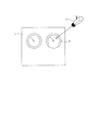
図1に示すように、本実施例においてメータ読取装置12は、カメラ11で撮影した画像を解析することで、電力設備1などの盤に取り付けられたメータ2の目盛を自動で読み取るものである。
Details of the meter reading apparatus according to the first embodiment of the present invention will be described with reference to FIGS.
As shown in FIG. 1, in the present embodiment, the
カメラ11は、例えば電力設備1の盤に取り付けられたメータ2に正対して設置され、メータ2を正面から撮影する。
The
そして、メータ読取装置12は、カメラ11により撮影した画像を解析してメータ2の目盛を読み取るものであり、図2に示すように、処理設定部12a、画像入力部12b、二値化処理部12c、回転角度ヒストグラム作成部12d、回転角度検出部12e、メータ目盛値計算部12f、読取結果データ伝送部12g、および記憶部12hを備えている。
The
処理設定部12aは、メータの読み取りに必要な情報であるメータ情報を設定する。メータ情報は記憶部12hに保管される。
画像入力部12bは、カメラ11で撮影した画像のデータ(画像データ)を入力する。画像データは記憶部12hに保管される。
二値化処理部12cは、記憶部12hからメータ情報と画像データを読み出し、メータの表示範囲の画像を二値化した画像データを作成する。画像データ(二値化)は記憶部12hに保管される。
The
The
The
回転角度ヒストグラム作成部12dは、記憶部12hからメータ情報と二値化した画像データを読み出し、メータ2の表示範囲において黒点を探索し、黒点の位置を後で詳述するメータ座標系に変換し、黒点の位置ベクトルの角度を求めて回転角度ヒストグラムを作成する。回転角度ヒストグラムは記憶部12hに保管される。
回転角度検出部12eは、記憶部12hから回転角度ヒストグラムを読み出し、回転角度ヒストグラムを調査してピーク位置を求め、そのピーク位置を指針回転角度とする。指針回転角度は記憶部12hに保管される。
The rotation angle
The rotation
メータ目盛値計算部12fは、記憶部12hからメータ情報と指針回転角度を読み出し、指針回転角度を関係式に代入してメータ目盛値を計算する。メータ目盛値は記憶部12hに保管される。
読取結果データ伝送部12gは、記憶部12hから指針回転角度とメータ目盛値を読み出し、読取結果データとして図示しない他の機器へ伝送する。
記憶部12hは、メータ情報、画像データ、画像データ(二値化)、回転角度ヒストグラム、指針回転角度、およびメータ目盛値等を保管する。
The meter scale
The reading result
The
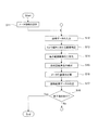
以下、図3を用いて本実施例に係るメータ読取装置によるメータ読み取り処理の流れを説明する。 Hereinafter, the flow of meter reading processing by the meter reading apparatus according to the present embodiment will be described with reference to FIG.
本実施例におけるメータ読み取り処理の大まかな流れを図3に示す。すなわち、まず、処理設定部12aによりメータ情報の設定を行い(ステップS1)、画像入力部12bによりメータ2を正面から撮影した画像をカメラ11から取得し(ステップS2)、二値化処理部12cにより表示範囲画像の二値化を行う(ステップS3)。
続いて、回転角度ヒストグラム作成部12dおよび回転角度検出部12eにより、指針回転角度を検出し(ステップS4)、メータ目盛値計算部12fによりメータ目盛値の計算を行い(ステップS5)、読取結果データ伝送部12gにより読取結果データの伝送を行う(ステップS6)。そして、終了指示がなければ(NO)ステップS2に戻り、終了指示があれば(YES)メータ読取処理を終了する(ステップS7)。
A rough flow of the meter reading process in this embodiment is shown in FIG. That is, first, meter information is set by the
Subsequently, the rotation angle
続いて、図4から図9を用いて、上述したステップS1からステップS6の内容について詳細に説明する。 Next, the contents of steps S1 to S6 described above will be described in detail with reference to FIGS.
〈メータ情報の設定(ステップS1)〉
図4に示すように、メータ情報の設定処理では、まず、メータ2の指針の回転中心を設定する(ステップS1a)。例えば、画像データとして図5(a)に示すようなメータ2Aの正面画像IAが得られた場合、図5(a)中×で示す点の位置をメータ2Aの指針2Aaの回転中心OAとして設定する。また、画像データとして図5(b)に示すようなメータ2Bの正面画像IBが得られた場合、図5(b)中に×で示す点の位置をメータ2Bの指針2Baの回転中心OBとして設定する。
<Setting of meter information (step S1)>
As shown in FIG. 4, in the meter information setting process, first, the rotation center of the pointer of the
続いて、指針の半径を設定する(ステップS1b)。例えば、画像データとして図5(a)に示すようなメータの正面画像IAが得られた場合、正面画像IA上の指針2Aaの回転中心OAから先端までの長さを指針の半径rAとして設定する。また、画像データとして図5(b)に示すようなメータの正面画像IBが得られた場合、正面画像IB上の指針2Baの回転中心OBから先端までの長さを指針の半径rBとして設定する。 Subsequently, the radius of the pointer is set (step S1b). For example, when a meter front image I A as shown in FIG. 5A is obtained as image data, the length from the rotation center O A to the tip of the pointer 2Aa on the front image I A is set to the radius r of the pointer. Set as A. Further, if the image data is the front image I B of the meter as shown in FIG. 5 (b) was obtained, the front image I B on the guidance 2Ba rotation center O B from the length to the tip of the pointer radius r of Set as B.
続いて、メータ2の表示範囲を設定する(ステップS1c)。例えば、画像データとして図5(a)に示すようなメータ2Aの正面画像IAが得られた場合、正面画像IA上における指針の稼動範囲を含む矩形範囲をメータ2Aの表示範囲2Abとして設定する。また、画像データとして図5(b)に示すようなメータ2Bの正面画像IBが得られた場合、正面画像IB上における指針の稼動範囲を含む矩形範囲をメータ2Bの表示範囲2Bbとして設定する。なお、図5(a)に示す例では、矩形形状のメータ2Aの表示部の内側をメータ2の表示範囲2Abとしており、図5(b)に示す例では、円形形状のメータ2Bの表示部よりも外側の部分を含む矩形範囲を表示範囲2Bbとしている。
Subsequently, the display range of the
以下、メータの正面画像をI、指針を2a、回転中心をO、メータの表示範囲を2b、指針2aの半径をrとして説明する。 In the following description, the front image of the meter is I, the pointer is 2a, the center of rotation is O, the meter display range is 2b, and the radius of the pointer 2a is r.
ステップS1dに続いては、目盛と指針の回転角度の関係式のパラメータを設定する(ステップS1d)。ここで、目盛と指針の回転角度の関係式は次の線形方程式(1)で表すことができる。
m=a×θ+b …(1)
ただし、mはメータ目盛値、θは回転角度、aは目盛−角度変換比率、bは目盛オフセット値である。関係式のパラメータは「目盛−角度変換比率a」と「目盛オフセット値b」であり、メータ情報の設定ではこれらのパラメータを設定する。
Following step S1d, a parameter of a relational expression between the scale and the rotation angle of the pointer is set (step S1d). Here, the relational expression between the scale and the rotation angle of the pointer can be expressed by the following linear equation (1).
m = a × θ + b (1)
Here, m is a meter scale value, θ is a rotation angle, a is a scale-angle conversion ratio, and b is a scale offset value. The parameters of the relational expression are “scale-angle conversion ratio a” and “scale offset value b”, and these parameters are set in the meter information setting.
これらのメータ情報の設定は次のいずれかの方法を用いる。
・ メータ情報を設定ファイル13(図2参照)へ書き込んでおき、メータ読取装置12が設定ファイル13を読み込むことでメータ情報の設定を行う。又は、
・ 伝送手段を通じてメータ読取装置に他の装置からメータ情報を送信する。又は、
・ メータ読取装置にメータ情報設定用のGUIを設けておき、マウスやキーボードなどの入力機器を操作することによってGUIへメータ情報を入力することでメータ情報を設定する。
The meter information is set using one of the following methods.
The meter information is written in the setting file 13 (see FIG. 2), and the
-Transmit meter information from other devices to the meter reader through the transmission means. Or
-A meter information setting GUI is provided in the meter reader, and meter information is set by inputting meter information to the GUI by operating an input device such as a mouse or a keyboard.
〈メータ正面画像データの入力(ステップS2)〉
メータ正面画像データの入力処理では、上述したように、画像入力部12bによりメータ2を正面から撮影した画像をカメラ11から取得する。
<Input of meter front image data (step S2)>
In the input process of the meter front image data, as described above, an image obtained by photographing the
〈表示範囲画像の二値化(ステップS3)〉
図6に示すように、表示範囲画像の二値化処理では、まず、メータの正面画像Iに対してメータ表示範囲2bにおける二値化しきい値を計算する(ステップS3a)。続いて、メータ表示範囲2bにおいて輝度値が二値化しきい値より低い点を黒(例えば、輝度値0)、それ以外の点を白(例えば、輝度値255)とする二値化処理を行う(ステップS3b)。
最後に、メータ表示範囲2bの二値化画像に対して白収縮処理を行う(ステップS3c)。
<Binarization of Display Range Image (Step S3)>
As shown in FIG. 6, in the binarization processing of the display range image, first, a binarization threshold value in the meter display range 2b is calculated for the front image I of the meter (step S3a). Subsequently, binarization processing is performed in which the point whose luminance value is lower than the binarization threshold in the meter display range 2b is black (for example, luminance value 0) and the other points are white (for example, luminance value 255). (Step S3b).
Finally, white shrinkage processing is performed on the binarized image in the meter display range 2b (step S3c).
本発明において、上述した表示範囲画像の二値化では、二値化しきい値を判別分析法により動的に自動計算する。また、白収縮処理は黒の点と隣接する全ての点を黒とすることで行う。ただし、指針2aの輝度値に対して背景の輝度値が暗い場合は、二値化したメータ表示範囲2bの白と黒の値を反転して、白だった点を黒にし、また黒だった点を白にしてから白収縮処理を行う。 In the present invention, in the above-described binarization of the display range image, the binarization threshold value is dynamically automatically calculated by the discriminant analysis method. Further, the white contraction process is performed by setting all points adjacent to the black point to black. However, if the brightness value of the background is darker than the brightness value of the pointer 2a, the white and black values in the binarized meter display range 2b are inverted so that the white point is black and black. The white contraction process is performed after the point is set to white.
〈指針回転角度の検出(ステップS4)〉
図7に示すように、指針回転角度の検出処理では、まず、回転角度のヒストグラムのクリア(初期化)を行い(ステップS4a)、メータ表示範囲2bにおいて黒点を探索し(ステップS4b)、黒点の有無を判断して(ステップS4c)、黒点がある場合(Yes)は黒点の位置をメータ座標系に変換する(ステップS4d)。黒点がない場合(No)は後述するステップS4jに移行する。
<Detection of pointer rotation angle (step S4)>
As shown in FIG. 7, in the detection process of the pointer rotation angle, first, the histogram of the rotation angle is cleared (initialized) (step S4a), and a black point is searched in the meter display range 2b (step S4b). The presence or absence is judged (step S4c), and if there is a black spot (Yes), the position of the black spot is converted into the meter coordinate system (step S4d). When there is no black dot (No), the process proceeds to step S4j described later.
ステップS4dに続いては、指針2aの回転中心Oから黒点までの距離を求め(ステップS4e)、求めた距離が指針2aの半径rより小さいかどうかを判定して(ステップS4f)、求めた距離が指針2aの半径r以上であれば(No)、ステップS4bに戻る。求めた距離が指針2aの半径rより小さければ(Yes)、続いて黒点の位置ベクトルの角度を求める(ステップS4g)。 Following step S4d, the distance from the rotation center O of the pointer 2a to the black point is obtained (step S4e), and it is determined whether the obtained distance is smaller than the radius r of the pointer 2a (step S4f). Is greater than or equal to the radius r of the pointer 2a (No), the process returns to step S4b. If the obtained distance is smaller than the radius r of the pointer 2a (Yes), then the angle of the black dot position vector is obtained (step S4g).
続いて、黒点の位置ベクトルの角度を回転角度ヒストグラムへ投票し(ステップS4h)、メータ表示範囲2bのすべての黒点を調べたか否かを判定して(ステップS4i)、メータ表示範囲2bのすべての黒点を調べていなければ(No)、ステップS4bに戻る。メータ表示範囲2bのすべての黒点を調べていれば(Yes)、回転角度ヒストグラムのピーク位置を求める(ステップS4j)。
最後に、回転角度ヒストグラムのピーク位置の角度を指針回転角度とする(ステップS4k)。
Subsequently, the angle of the position vector of the black spot is voted on the rotation angle histogram (step S4h), and it is determined whether or not all the black spots in the meter display range 2b are checked (step S4i). If the black spot has not been examined (No), the process returns to step S4b. If all the black dots in the meter display range 2b have been examined (Yes), the peak position of the rotation angle histogram is obtained (step S4j).
Finally, the angle at the peak position of the rotation angle histogram is set as the pointer rotation angle (step S4k).
本発明のメータ座標系を図8(a)に示す。指針の回転中心Oをメータ座標系の原点とし、画像の横軸方向(u軸)と同じ方向にy軸を、画像の縦軸方向(v軸)と逆の方向にx軸をとる。また、原点を中心とした時計軸周りに回転角度を設定し、x軸の負側を0度として、360度の角度で示す。ある黒点をメータ座標系に変換した例を図8(b)に示す。画像上の位置(u,v)をメータ座標系上の位置(x,y)に変換し、回転角度θを0〜360度の値で示している。また、メータ座標系上の位置(x,y)は図8(c)に示すようにメータ座標系において原点から位置(x,y)への位置ベクトルvとしても表現できる。 The meter coordinate system of the present invention is shown in FIG. The rotation center O of the pointer is the origin of the meter coordinate system, the y axis is in the same direction as the horizontal axis direction (u axis) of the image, and the x axis is in the direction opposite to the vertical axis direction (v axis) of the image. In addition, a rotation angle is set around a clockwise axis with the origin as the center, and the negative side of the x axis is set to 0 degree, and the angle is indicated by 360 degrees. An example in which a certain black point is converted into the meter coordinate system is shown in FIG. The position (u, v) on the image is converted to the position (x, y) on the meter coordinate system, and the rotation angle θ is indicated by a value of 0 to 360 degrees. The position (x, y) on the meter coordinate system can also be expressed as a position vector v from the origin to the position (x, y) in the meter coordinate system as shown in FIG.
図9に、本発明の方法によりメータ表示範囲のすべての黒点に対して回転角度ヒストグラムを作成した模式図を示す。図9(a)に示すように、指針2aに起因する黒点3cはメータ座標系の原点に対して放射状に分布するため、図9(b)に示す回転角度ヒストグラム上において指針2aの回転角度Θで黒点数のピークが発生する。指針2aの影や表示板の文字など他の要因による黒点はメータ座標系の原点に対して放射状に分布しないため、回転角度ヒストグラム上では広範囲の回転角度に分散することになり黒点数は少なくなる。
本発明では回転角度ヒストグラムの黒点数が最大の位置をピーク位置として求め、このピーク位置の角度を指針回転角度とする。
FIG. 9 shows a schematic diagram in which a rotation angle histogram is created for all black spots in the meter display range by the method of the present invention. As shown in FIG. 9 (a), the
In the present invention, the position where the number of black spots in the rotation angle histogram is the maximum is obtained as the peak position, and the angle of this peak position is set as the pointer rotation angle.
〈メータ目盛値の計算(ステップS5)〉
メータ目盛値mと指針回転角度θの関係式は先に述べた線形方程式(1)で表される。そこで、メータ目盛値の計算処理では、処理設定部12aにより設定した「目盛−角度変換比率a」及び「目盛オフセット値b」と、指針回転角度θとを関係式(1)に代入し、メータ目盛値mを算出する。
<Calculation of meter scale value (step S5)>
The relational expression between the meter scale value m and the pointer rotation angle θ is expressed by the linear equation (1) described above. Therefore, in the meter scale value calculation process, the “scale-angle conversion ratio a” and “scale offset value b” set by the
〈読取結果データの伝送(ステップS6)〉
読取結果データの伝送処理では、指針回転角度θおよびメータ目盛値mを読取結果データとしてまとめて伝送する。
<Transmission of reading result data (step S6)>
In the reading result data transmission process, the pointer rotation angle θ and the meter scale value m are collectively transmitted as reading result data.
このように構成される本実施例に係るメータ読取装置によれば、次の作用効果が得られる。
(1)カメラで撮影した画像を解析することで、電力設備1などの盤に取り付けたメータを自動で読み取ることができる。
(2)画像全体を極座標変換するような大きなメモリ操作や複雑な計算をすることなく、電力設備1などの盤に取り付けたメータを自動で読み取ることができる。
(3)指針の回転中心に対するひとつの円周上の輝度変化のみから指針回転角度を求める方法に対して、指針に起因する黒点全体を使った回転角度ヒストグラムから指針回転角度を求めるため、ノイズに強く誤計測が発生しにくい。
(4)輝度変化が発生してもメータを自動で読み取ることができる。
(5)画像パターンとの照合を行うことなく指針の回転角度を求めることができるため、指針の回転角度ごとの画像パターンを用意しておく必要がない。
According to the meter reading apparatus according to this embodiment configured as described above, the following operational effects can be obtained.
(1) By analyzing an image taken with a camera, a meter attached to a panel such as the
(2) It is possible to automatically read a meter attached to a panel such as the
(3) In contrast to the method of obtaining the pointer rotation angle only from the luminance change on one circumference with respect to the center of rotation of the pointer, the pointer rotation angle is obtained from the rotation angle histogram using the entire black spot caused by the pointer, so noise Strongly erroneous measurement is unlikely to occur.
(4) The meter can be automatically read even if a luminance change occurs.
(5) Since the rotation angle of the pointer can be obtained without performing comparison with the image pattern, it is not necessary to prepare an image pattern for each rotation angle of the pointer.
図10を用いて本発明の実施例2に係るメータ読取装置の詳細を説明する。本実施例に係るメータ読取装置は、上述した実施例1に係るメータ読取装置に比較して、指針回転角度θの詳細値を補間により求める点が異なる。 Details of the meter reading apparatus according to the second embodiment of the present invention will be described with reference to FIG. The meter reading device according to the present embodiment is different from the meter reading device according to the first embodiment described above in that the detailed value of the pointer rotation angle θ is obtained by interpolation.
すなわち、本実施例に係るメータ読取装置では、上述した実施例1の回転角度ヒストグラムのピーク位置を求める工程(図7のステップS4j)において、回転角度ヒストグラムのピーク位置を単に黒点数が最大の位置として求めるのではなく、ピーク位置の黒点数とピーク位置前後の黒点数の三点を使ってピーク位置付近のヒストグラム形状を二次曲線で補間し、この二次曲線のピーク位置を回転角度ヒストグラムのピーク位置(角度)として求め、このピーク位置に対応する回転角度を指針回転角度とする点が、実施例1と異なる。その他の構成は上述した実施例1と同様であり、以下、重複する説明は省略し、異なる点を中心に説明する。 That is, in the meter reading apparatus according to the present embodiment, in the step of obtaining the peak position of the rotation angle histogram of the first embodiment (step S4j in FIG. 7), the peak position of the rotation angle histogram is simply the position where the number of black spots is the maximum. The histogram shape near the peak position is interpolated with a quadratic curve using the three points of the number of black spots at the peak position and the number of black spots before and after the peak position, and the peak position of this quadratic curve is plotted on the rotation angle histogram. The difference from the first embodiment is that it is obtained as a peak position (angle) and the rotation angle corresponding to this peak position is used as the pointer rotation angle. The other configuration is the same as that of the first embodiment described above, and the following description will be omitted while omitting the overlapping description.
図10に、指針回転角度の詳細値を補間により求める処理の模式図を示す。回転角度ヒストグラムの作成は離散的な角度幅に対して黒点数を投票することで行うため、図10(a)に示す回転角度ヒストグラムのピーク位置の近傍を拡大すると、図10(b)に示すようになる。
そこで、本実施例では、回転角度検出部12eにより回転角度ヒストグラムを調査してピーク位置を求める際に、二次曲線補間によるピーク位置検出を行う。すなわち、黒点数の最大値と、この黒点数が最大となる角度の両隣の角度の黒点数との合計三つの黒点数を利用して近似曲線(二次曲線)を求め、この近似曲線のピーク位置を指針回転角度として検出する。
このような処理を行うことにより、実施例1では図10(b)に示す位置(角度)Θをピーク位置として検出するのに対し、本実施例では図10(b)に示す位置(角度)Θ’がピーク位置として検出される。
FIG. 10 shows a schematic diagram of processing for obtaining the detailed value of the pointer rotation angle by interpolation. Since the rotation angle histogram is created by voting the number of black spots with respect to the discrete angle width, when the vicinity of the peak position of the rotation angle histogram shown in FIG. 10A is enlarged, the rotation angle histogram is shown in FIG. It becomes like this.
Therefore, in this embodiment, when the
By performing such processing, the position (angle) Θ shown in FIG. 10B is detected as the peak position in the first embodiment, whereas the position (angle) shown in FIG. 10B is detected in the present embodiment. Θ ′ is detected as the peak position.
このように、回転角度ヒストグラムの作成は離散的な角度幅に対して黒点数を投票するのに対し、本実施例では、二次曲線補間を行って、離散的な角度ではなく連続的な角度からピーク位置を求めるため、ピーク位置が離散的な値を取る実施例1に係るメータ読取装置による作用効果に比較して、より正確な指針回転角度を求めることができる。 As described above, the rotation angle histogram is created by voting the number of sunspots with respect to a discrete angle width, whereas in this embodiment, a quadratic curve interpolation is performed to obtain a continuous angle instead of a discrete angle. Therefore, a more accurate pointer rotation angle can be obtained as compared with the operational effect of the meter reading apparatus according to the first embodiment in which the peak position takes discrete values.
図11から図13を用いて本発明の実施例3に係るメータ読取装置の詳細を説明する。本実施例に係るメータ読取装置は、上述した実施例1に係るメータ読取装置に比較して、ピーク位置近傍のグラフ形状を確認する点が異なる。本実施例では、追加の処理パラメータとして、実施例1のメータ情報にピーク角度幅を追加し、これを予め設定しておく。 Details of the meter reading apparatus according to the third embodiment of the present invention will be described with reference to FIGS. The meter reading device according to the present embodiment is different from the meter reading device according to the first embodiment described above in that the graph shape near the peak position is confirmed. In the present embodiment, a peak angle width is added to the meter information of the first embodiment as an additional processing parameter, and this is set in advance.
図11に本実施例に係るメータ読取装置12の構成を示す。本実施例におけるメータ読取装置12は、図2に示し上述した実施例1に係るメータ読取装置12と比較して、処理設定部12a、回転角度検出部12e、メータ目盛値計算部12f、読取結果データ伝送部12g、記憶部12hの機能が一部異なる。
FIG. 11 shows the configuration of the
すなわち、処理設定部12aは、メータ読み取りに必要なメータ情報を設定する際、メータ情報として実施例1で設定する情報に加えて、ピーク角度幅の設定を行う。ピーク角度幅を含むメータ情報は、記憶部12hに保管される。
また、回転角度検出部12eは、記憶部12hからメータ情報と回転角度ヒストグラムとを読み出し、回転角度ヒストグラムを調査してピーク位置を求め、ピーク有無データを作成し、ピークがある場合はそのピーク位置を指針回転角度とする。ピーク有無データ及び指針回転角度は記憶部12hに保管される。
That is, when setting the meter information necessary for meter reading, the
The rotation
メータ目盛値計算部12fは、記憶部12hからメータ情報とピーク有無データと指針回転角度とを読み出し、ピークがある場合は指針回転角度を関係式に代入してメータ目盛値を計算する。メータ目盛値は記憶部12hに保管される。
読取結果データ伝送部12gは、ピーク有無データと指針回転角度およびメータ目盛値を読取結果データとしてまとめて伝送する。
記憶部12hは、ピーク角度幅を含むメータ情報、画像データ、画像データ(二値化)、回転角度ヒストグラム、ピーク有無データ、指針回転角度、およびメータ目盛値等を保管する。
The meter scale
The reading result
The
なお、画像入力部12bおよび回転角度ヒストグラム作成部12dの機能については上述した実施例1と同様であり、重複する説明は省略する。
The functions of the
以下、図12を用いて本実施例における回転角度ヒストグラムのピーク位置を求める工程の詳細を説明する。図12に示すように、回転角度検出部12eでは、次の手順でグラフ形状を確認しながらピーク位置を探索する。
まず、回転角度ヒストグラムを調査し黒点数が最大となる位置(角度)を求める(ステップS4j−1)。続いて、黒点数が最大となる位置(角度)を挟んで黒点数が最大値の半分の値になる位置(角度)を求める(ステップS4j−2)。そして、求めた黒点数が最大値の半分の値となる位置(角度)の間をピーク候補範囲(図13(b)のW1,W2参照)とし、その間隔をピーク候補間隔とする(ステップS4j−3)。
その後、ピーク候補間隔が予め設定したピーク角度幅以下か否かを判定する(ステップS4j−4)。
Hereinafter, the details of the step of obtaining the peak position of the rotation angle histogram in this embodiment will be described with reference to FIG. As shown in FIG. 12, the
First, the rotation angle histogram is examined to determine the position (angle) at which the number of black spots is maximized (step S4j-1). Subsequently, a position (angle) at which the number of black spots is half the maximum value across the position (angle) at which the number of black spots is maximized is obtained (step S4j-2). Then, a position between the positions (angles) at which the obtained number of black spots is half the maximum value is set as a peak candidate range (see W 1 and W 2 in FIG. 13B), and the interval is set as a peak candidate interval ( Step S4j-3).
Thereafter, it is determined whether or not the peak candidate interval is equal to or less than a preset peak angle width (step S4j-4).
ピーク候補間隔がピーク角度幅より大きければ(No)、ピーク候補範囲以外の位置で黒点数が最大となる位置を求め(ステップS4j−5)、上述したステップS4j−2に戻る。
一方、ピーク候補間隔がピーク角度幅以下であれば(Yes)、黒点数の最大値が指針2aの半径の半分より大きいか否かを判定する(ステップS4j−6)。そして、黒点数の最大値が指針2aの半径の半分より大きければ(Yes)、先に求めた黒点数が最大となる位置をピーク位置として求め(ステップS4j−7)、ピーク位置の探索を終了する。黒点数の最大値が指針2aの半径以下であれば(No)、ピークがないと設定して(ステップS4j−8)、ピーク位置の探索を終了する。
If the peak candidate interval is larger than the peak angle width (No), a position where the number of black spots is maximized at a position other than the peak candidate range is obtained (step S4j-5), and the process returns to step S4j-2 described above.
On the other hand, if the peak candidate interval is equal to or smaller than the peak angle width (Yes), it is determined whether or not the maximum value of the number of black spots is larger than half the radius of the pointer 2a (step S4j-6). If the maximum value of the number of black spots is larger than half of the radius of the pointer 2a (Yes), the position where the number of black spots previously determined is the maximum is determined as the peak position (step S4j-7), and the search for the peak position is completed. To do. If the maximum value of the number of black spots is equal to or less than the radius of the pointer 2a (No), it is set that there is no peak (step S4j-8), and the search for the peak position is terminated.
すなわち、本実施例に係るメータ読取装置は、上述した実施例1の回転角度ヒストグラムのピーク位置を求める工程(図6のステップS4j)において、ピーク位置近傍のグラフ形状を確認し、指針として適切でないグラフ形状であれば該当のピーク位置を破棄して別のピーク位置を探索する点で、実施例1と異なる。 That is, the meter reading apparatus according to the present embodiment checks the graph shape in the vicinity of the peak position in the step of obtaining the peak position of the rotation angle histogram of the first embodiment (step S4j in FIG. 6) and is not appropriate as a guideline. The graph shape is different from the first embodiment in that the corresponding peak position is discarded and another peak position is searched.
通常、指針2aは細い針形状をしているため、図13(a)に示す指針2aに対応する黒点が存在する範囲(以下、黒点領域という)3cは、回転角度ヒストグラム上において図13(b)に示す4cのように急峻なピークを形成するため、ピーク候補間隔W1は狭くなる。これに対し、例えば図13(a)に示すようにメータ表示範囲2bに何らかの大きな影が映っているような場合、影に対応する黒点の範囲3eは、回転角度ヒストグラム上で図13(b)に示す4eのように黒点数が多くても急峻なピークを持たず、ピーク候補間隔W2は広くなる。
Usually, since the pointer 2a has a thin needle shape, a range (hereinafter referred to as a black dot region) 3c where a black point corresponding to the pointer 2a shown in FIG. ) in order to form a steep peak like 4c showing a peak candidate interval W 1 becomes narrow. On the other hand, for example, as shown in FIG. 13A, when a certain large shadow appears in the meter display range 2b, the
また、指針2aの半径は画像上で設定しているため、指針2aの半径と回転角度ヒストグラムにおける指針2aに起因する黒点数の最大数はほぼ一致する。回転角度ヒストグラム上において黒点数が指針2aの半径の半分に満たなければ、メータカバーの反射や何らかの遮蔽物によりメータ自身が画像上で見えない可能性がある。もしくは影に指針2a全体が覆われておりピーク位置が見つからないという可能性も考えられる。このように、回転角度ヒストグラム上において黒点数が指針2aの半径の半分に満たない場合、本実施例ではピークが無いと判断する。 In addition, since the radius of the pointer 2a is set on the image, the radius of the pointer 2a and the maximum number of black spots caused by the pointer 2a in the rotation angle histogram substantially coincide. If the number of black spots on the rotation angle histogram is less than half of the radius of the pointer 2a, the meter itself may not be visible on the image due to the reflection of the meter cover or some obstruction. Alternatively, there is a possibility that the entire pointer 2a is covered with a shadow and the peak position cannot be found. Thus, when the number of black spots is less than half of the radius of the pointer 2a on the rotation angle histogram, it is determined that there is no peak in this embodiment.
本実施例に係るメータ読取装置によれば、実施例1に係るメータ読取装置による作用効果に加えて、影による影響を排除して回転角度ヒストグラムから指針2aによるピーク位置を正しく求めることができる。また遮蔽物や影が指針2aを覆って指針2aの検出が困難である場合はピークがないと判断することで、画像の状態における計測の可否を検出することができる。 According to the meter reading apparatus according to the present embodiment, in addition to the operational effects of the meter reading apparatus according to the first embodiment, the peak position by the pointer 2a can be correctly obtained from the rotation angle histogram by removing the influence of the shadow. Further, when it is difficult to detect the pointer 2a because the shielding object or shadow covers the pointer 2a, it is possible to detect whether or not measurement is possible in the image state by determining that there is no peak.
なお、本実施例においても上述した実施例2と同様に指針回転角度の詳細値を補間により求めてもよい。また、本実施例では黒点数が最大となる位置(角度)を挟み、黒点数が最大値の半分の値になる位置(角度)間をピーク候補範囲とする例を示したが、ピーク候補範囲を設定するための値は黒点数が最大値の半分の値となる位置でなくともよく、必要に応じて適宜設定することが可能である。 In this embodiment as well, the detailed value of the pointer rotation angle may be obtained by interpolation as in the second embodiment. Further, in this embodiment, an example is shown in which the peak candidate range is set between the positions (angles) where the number of black spots is the maximum and the position (angle) where the number of black spots is half the maximum value. The value for setting may not be a position where the number of sunspots is half the maximum value, and can be set as needed.
図14から図20を用いて本発明の実施例4に係るメータ読取装置について説明する。
図14に示すように、本実施例に係るメータ読取装置は、実施例1に係るメータ読取装置に対し、メータ2の正面に対して上方に設置したカメラ11によって撮影した画像からメータ2の目盛値を読み取る点で実施例1と異なる。
A meter reading apparatus according to
As shown in FIG. 14, the meter reading apparatus according to the present embodiment is a scale of the
図15に示すように、本実施例においてメータ読取装置12は、処理設定部12a、画像入力部12b、二値化処理部12c、回転角度ヒストグラム作成部12d、回転角度検出部12e、メータ目盛値計算部12f、読取結果データ伝送部12g、記憶部12hに加えて、カメラ傾き補正処理部12iを備えている。
As shown in FIG. 15, in this embodiment, the
本実施例では、メータの指針2aの回転中心Oと指針2aの半径およびメータ表示範囲2bは予め別の手段により求めるものとし、これらのメータ読み取りに必要な情報は予めメータ情報として処理設定部12aにより設定しておく。メータ2の目盛と指針2aの回転角度の関係式についても予め設定する。また、カメラ11をメータ2の正面以外に設置し、画像撮影を行う場合には、メータ2の正面画像に基づき画像データの補正を行う。そのためメータ2を正面から撮影した画像の画像特徴量についても予め設定しておく。
In this embodiment, the rotation center O of the pointer 2a of the meter, the radius of the pointer 2a, and the meter display range 2b are obtained in advance by another means, and information necessary for reading these meters is previously set as meter information in the
カメラ傾き補正処理部12iは、記憶部12hから画像データを読み出し、傾きを補正した画像データ(傾き補正)を作成する。画像データ(傾き補正)は記憶部12hに保管される。
二値化処理部12cは、記憶部12hからメータ情報と画像データ(傾き補正)とを読み出し、メータの表示範囲の傾きを補正した画像を二値化した画像データ(二値化)を作成する。画像データ(二値化)は記憶部12hに保管される。
記憶部12hは、メータ情報、画像データ、画像データ(傾き補正)、画像データ(二値化)、回転角度ヒストグラム、指針回転角度、およびメータ目盛値等を保管する。
The camera tilt
The
The
なお、画像入力部12b、回転角度ヒストグラム作成部12d、回転角度検出部12e、メータ目盛値計算部12f、読取結果データ伝送部12gについては、上述した実施例1で説明した構成と同様であり、重複する説明は省略する。
The
以下、図16を用いて本実施例に係るメータ読取装置によるメータ読取の流れを説明する。 Hereinafter, the flow of meter reading by the meter reading apparatus according to the present embodiment will be described with reference to FIG.
本実施例におけるメータ読取の大まかな流れを図15に示す。すなわち、まず、処理設定部12aによりメータ情報の設定を行い(ステップS11)、画像入力部12bによりメータ2を撮影したメータの画像をカメラ11から取得し(ステップS12)、カメラ傾き補正処理部12iによりカメラの姿勢・位置に応じてメータの画像を補正し(ステップS13)、二値化処理部12cにより表示範囲画像の二値化を行う(ステップS14)。
A rough flow of meter reading in this embodiment is shown in FIG. That is, first, meter information is set by the
続いて、回転角度ヒストグラム作成部12dおよび回転角度検出部12eにより、指針回転角度を検出し(ステップS15)、メータ目盛値計算部12fによりメータ目盛値の計算を行い(ステップS16)、読取結果データ伝送部12gにより読取結果データの伝送を行う(ステップS17)。そして、終了指示がなければ(NO)ステップS2に戻り、終了指示があれば(YES)メータ読取処理を終了する(ステップS18)。
Subsequently, the rotation angle
続いて、図15に示したステップS11からステップS17の内容について説明する。 Subsequently, the contents of steps S11 to S17 shown in FIG. 15 will be described.
〈メータ情報の設定(ステップS11)〉
図17に示すステップS11aからステップS11dまでの処理は図4に示し実施例1において説明したステップS1aからステップS1dまでの処理と同様であり、重複する説明は省略する。
本実施例では、ステップS11dでメータ目盛値mと指針回転角度θの関係式のパラメータを設定した後、メータ正面画像の画像特徴量を設定する(ステップS11e)。画像特徴量は、メータの正面画像内において例えば特許第5712801号公報に開示されている手法を用いて抽出し、メータ正面画像特徴量として設定する。
<Setting of meter information (step S11)>
The processing from step S11a to step S11d shown in FIG. 17 is the same as the processing from step S1a to step S1d shown in FIG. 4 and described in the first embodiment, and redundant description is omitted.
In this embodiment, after setting the parameter of the relational expression between the meter scale value m and the pointer rotation angle θ in step S11d, the image feature amount of the meter front image is set (step S11e). The image feature amount is extracted from the front image of the meter using, for example, a technique disclosed in Japanese Patent No. 5721801 and set as a meter front image feature amount.
〈カメラの姿勢・位置に対する補正(ステップS13)〉
図18に示すように、カメラの姿勢・位置に対する補正処理では、まず、カメラ11から入力した画像(以下、入力画像)から画像特徴量を抽出する(ステップS13a)。続いて、上述したステップS11eで設定したメータ正面画像の画像特徴量と入力画像の画像特徴量とを照合する(ステップS13b)。すなわち、予め設定したメータ正面画像の特徴量と入力した画像の画像特徴を用いて、メータの文字盤部分と指針部分の二箇所でそれぞれの部分で画像特徴量の照合を行う。なお、カメラの姿勢・位置に対する補正では画像特徴量抽出、画像照合方法として例えば特許第5712801号公報に開示されている手法を用いる。
そして、照合結果から入力画像撮影時のカメラの傾きおよび設置位置情報を算出する(ステップS13c)。すなわち、画像特徴量同士を照合させた結果から予め設定したメータ正面画像に対しての入力画像の傾き角度および画像撮影位置を算出する。
その後、算出した傾き、設置位置を用いて図19に示すように入力画像の補正を行う(ステップS13d)。図19にカメラ11をメータ2の上方向から撮影した画像を射影変換した例を示す。すなわち、図19(a)に示すようなカメラ11をメータ2の上方向から撮影した画像に対して、傾き角度、設置位置情報を用いて射影変換を行うことでカメラの傾きについて補正し、図19(b)に示すような画像データ(傾き補正)を取得する。射影変換を行うことで、カメラ11の設置位置や傾きに対しての補正を行うことができる。
<Correction to Camera Posture / Position (Step S13)>
As shown in FIG. 18, in the correction process for the posture / position of the camera, first, an image feature amount is extracted from an image input from the camera 11 (hereinafter, input image) (step S13a). Subsequently, the image feature amount of the meter front image set in step S11e described above is collated with the image feature amount of the input image (step S13b). That is, using the feature value of the meter front image set in advance and the image feature of the input image, the image feature value is collated at each of the two parts, the dial part of the meter and the pointer part. In the correction of the camera posture / position, for example, a method disclosed in Japanese Patent No. 5721801 is used as an image feature amount extraction and image collation method.
Then, the camera tilt and the installation position information at the time of capturing the input image are calculated from the collation result (step S13c). That is, the inclination angle and image photographing position of the input image with respect to the preset meter front image are calculated from the result of collating the image feature amounts.
Thereafter, the input image is corrected using the calculated inclination and installation position as shown in FIG. 19 (step S13d). FIG. 19 shows an example of projective transformation of an image taken by the
〈表示範囲画像の二値化(ステップS14)〉
図20に示すように、表示範囲の二値化処理では、まず、メータの補正された画像に対してメータ表示範囲における二値化しきい値を計算する(ステップS14a)。続いて、メータの表示範囲における輝度値が二値化しきい値より低い点を黒(輝度値0)、それ以外の点を白(輝度値255)とする(ステップS14b)。そして、メータの表示範囲の二値画像に対して白収縮処理をかける(ステップS14c)。
本実施例では、表示範囲画像の二値化において二値化しきい値を判別分析法により動的に自動計算する。また白収縮処理は黒の点と隣接する全ての点を黒とすることで行う。ただし、指針の輝度値に対して背景の輝度値が暗い場合は、二値化したメータの表示範囲の白と黒の値を反転して、白だった点を黒、黒だった点を白にしてから白収縮処理を行う。
<Binarization of Display Range Image (Step S14)>
As shown in FIG. 20, in the binarization process of the display range, first, a binarization threshold value in the meter display range is calculated for the corrected image of the meter (step S14a). Subsequently, a point where the luminance value in the display range of the meter is lower than the binarization threshold is black (luminance value 0), and the other points are white (luminance value 255) (step S14b). Then, white shrinkage processing is applied to the binary image in the meter display range (step S14c).
In this embodiment, the binarization threshold value is automatically and dynamically calculated by the discriminant analysis method in binarization of the display range image. The white shrinking process is performed by setting all the points adjacent to the black point to black. However, if the brightness value of the background is darker than the brightness value of the pointer, the white and black values in the binarized meter display range are reversed so that the white point is black and the black point is white. After that, white shrinkage processing is performed.
なお、ステップS12、ステップS15、およびステップS16の処理については、実施例1において説明したステップS2、ステップS4、及びステップS5の処理と同様であり、ここでの詳細な説明は省略する。 In addition, about the process of step S12, step S15, and step S16, it is the same as that of the process of step S2, step S4, and step S5 demonstrated in Example 1, and detailed description here is abbreviate | omitted.
本実施例に係るメータ読取装置によれば、実施例1に係るメータ読取装置による作用効果に加えて、カメラ11の設置位置がメータ2の正面に対して上下方向および左右方向の移動を含む場合にもメータの自動読み取りを行うことができる。
According to the meter reading device according to the present embodiment, in addition to the operational effects of the meter reading device according to the first embodiment, the installation position of the
なお、本実施例ではカメラ11をメータ2の正面に対して上方に設置する例を示したが、カメラ11を設置する位置は図13に示すようなメータ2を見下げる位置に限定されるものではなく、メータ2の正面に対して左右方向、または上下方向に設置するなど、カメラ11をメータ2の正面以外であれば本実施例を適用することができる。
In addition, although the example which installed the
なお、本実施例においても、上述した実施例2と同様に指針回転角度の詳細値を補間により求める構成とする、又は、上述した実施例3と同様にピーク位置近傍のグラフ形状を確認する構成としてもよい。 In this embodiment as well, the detailed value of the pointer rotation angle is obtained by interpolation as in the second embodiment described above, or the graph shape near the peak position is confirmed as in the third embodiment described above. It is good.
本発明は、カメラで撮影した画像を解析することでメータの目盛を読み取るメータ読取装置に適用することができる。 The present invention can be applied to a meter reading device that reads a scale of a meter by analyzing an image photographed by a camera.
2,2A,2B メータ
2Aa,2Ba 指針
2Ab,2Bb メータ表示範囲
3a,3b,3c,3d,3e 黒点領域
11 カメラ
12 メータ読取装置
12a 処理設定部
12b 画像入力部
12c 二値化処理部
12d 回転角度ヒストグラム作成部
12e 回転角度検出部
12f メータ目盛値計算部
12g 読取結果データ伝送部
12h 記憶部
12i カメラ傾き補正処理部
13 設定ファイル
IA,IB メータの正面画像
2, 2A, 2B Meter 2Aa, 2Ba Pointer 2Ab, 2Bb
Claims (6)
前記メータの画像を二値化した画像データを作成する二値化処理部と、
前記二値化した画像データから黒点を探索し、前記黒点の分布をメータ座標系に変換してなる回転角度ヒストグラムを作成する回転角度ヒストグラム作成部と、
前記回転角度ヒストグラムの黒点数が最大となる角度を指針回転角度として検出する回転角度検出部と、
前記指針回転角度からメータ目盛値を算出するメータ目盛値計算部と
を備えることを特徴とするメータ読取装置。 In the meter reading device that reads the scale value of the meter from the image of the meter photographed by the camera,
A binarization processing unit for creating image data obtained by binarizing the image of the meter;
A rotation angle histogram creating unit that searches for black spots from the binarized image data and creates a rotation angle histogram formed by converting the distribution of the black spots into a meter coordinate system;
A rotation angle detector that detects an angle at which the number of black spots in the rotation angle histogram is maximum as a pointer rotation angle;
A meter reading device comprising: a meter scale value calculation unit that calculates a meter scale value from the pointer rotation angle.
ことを特徴とする請求項1記載のメータ読取装置。 The meter reading apparatus according to claim 1, wherein the rotation angle detection unit detects the peak position of the quadratic curve as a pointer rotation angle by interpolating the number of black spots of the rotation angle histogram with a quadratic curve.
ことを特徴とする請求項1又は請求項2記載のメータ読取装置。 The rotation angle detection unit obtains an angle at which the number of black spots is equal to or greater than a preset value before and after the angle at which the number of black spots is maximum, and a range of angles where the number of black spots is equal to or greater than the preset value is a predetermined angle 3. The meter reading apparatus according to claim 1, wherein an angle at which the number of sunspots is maximum when the number is less than the range is output as a pointer rotation angle.
ことを特徴とする請求項3記載のメータ読取装置。 The rotation angle detection unit determines that the angle at which the black spot is the maximum is not a pointer when the range of angles where the number of black spots is equal to or greater than the preset value is larger than the predetermined angle range. The meter reader according to claim 3.
前記二値化処理部が、補正した前記メータの画像を二値化した画像データを作成する
ことを特徴とする請求項1から請求項4のいずれか1項に記載のメータ読取装置。 A camera tilt correction processing unit that corrects an image of the meter captured by the camera based on a reference image captured from the front of the meter,
5. The meter reading apparatus according to claim 1, wherein the binarization processing unit creates image data obtained by binarizing the corrected image of the meter. 6.
前記カメラによって撮影した画像を入力する画像入力部と、
少なくとも前記指針回転角度及び前記メータ目盛値を伝送する読取結果データ伝送部と
を備える
ことを特徴とする請求項1から請求項5のいずれか1項に記載のメータ読取装置。 A process setting section for setting meter information necessary for meter reading;
An image input unit for inputting an image taken by the camera;
The meter reading device according to any one of claims 1 to 5, further comprising a reading result data transmission unit that transmits at least the pointer rotation angle and the meter scale value.
Priority Applications (1)
| Application Number | Priority Date | Filing Date | Title |
|---|---|---|---|
| JP2016004946A JP2017126187A (en) | 2016-01-14 | 2016-01-14 | Meter reading device |
Applications Claiming Priority (1)
| Application Number | Priority Date | Filing Date | Title |
|---|---|---|---|
| JP2016004946A JP2017126187A (en) | 2016-01-14 | 2016-01-14 | Meter reading device |
Publications (1)
| Publication Number | Publication Date |
|---|---|
| JP2017126187A true JP2017126187A (en) | 2017-07-20 |
Family
ID=59364960
Family Applications (1)
| Application Number | Title | Priority Date | Filing Date |
|---|---|---|---|
| JP2016004946A Pending JP2017126187A (en) | 2016-01-14 | 2016-01-14 | Meter reading device |
Country Status (1)
| Country | Link |
|---|---|
| JP (1) | JP2017126187A (en) |
Cited By (8)
| Publication number | Priority date | Publication date | Assignee | Title |
|---|---|---|---|---|
| JP2019095225A (en) * | 2017-11-20 | 2019-06-20 | アズビル株式会社 | Method and equipment for automatic reading of analog meter value |
| WO2019181337A1 (en) * | 2018-03-23 | 2019-09-26 | 株式会社 東芝 | Reading system, reading method, and storage medium |
| JP2019169116A (en) * | 2018-03-23 | 2019-10-03 | 株式会社東芝 | Reading system, reading method, program and storage medium |
| JP2020024741A (en) * | 2018-04-27 | 2020-02-13 | 株式会社東芝 | Reading system, reading method, program, and recording medium |
| CN111401377A (en) * | 2020-03-13 | 2020-07-10 | 北京市商汤科技开发有限公司 | Instrument data reading method and device, electronic equipment and storage medium |
| JP2020160691A (en) * | 2019-03-26 | 2020-10-01 | 株式会社フュージョンテク | Remote meter reading computer, method and program of the same |
| JP2020194275A (en) * | 2019-05-27 | 2020-12-03 | 株式会社東芝 | Reading system, mobile body, reading method, program, and storage medium |
| US11468666B2 (en) | 2018-12-12 | 2022-10-11 | Kabushiki Kaisha Toshiba | Reading support system and moving body |
Citations (4)
| Publication number | Priority date | Publication date | Assignee | Title |
|---|---|---|---|---|
| JPH0719814A (en) * | 1993-06-22 | 1995-01-20 | Mitsubishi Electric Corp | Meter indication reader |
| JPH1196372A (en) * | 1997-09-16 | 1999-04-09 | Omron Corp | Method and device for processing image and recording medium of control program for image processing |
| JP2002288777A (en) * | 2001-03-23 | 2002-10-04 | Mitsubishi Electric Corp | Automatic meter reading device and automatic meter reading method |
| WO2014203403A1 (en) * | 2013-06-17 | 2014-12-24 | 富士通株式会社 | Image processing device, image processing method, and image processing program |
-
2016
- 2016-01-14 JP JP2016004946A patent/JP2017126187A/en active Pending
Patent Citations (4)
| Publication number | Priority date | Publication date | Assignee | Title |
|---|---|---|---|---|
| JPH0719814A (en) * | 1993-06-22 | 1995-01-20 | Mitsubishi Electric Corp | Meter indication reader |
| JPH1196372A (en) * | 1997-09-16 | 1999-04-09 | Omron Corp | Method and device for processing image and recording medium of control program for image processing |
| JP2002288777A (en) * | 2001-03-23 | 2002-10-04 | Mitsubishi Electric Corp | Automatic meter reading device and automatic meter reading method |
| WO2014203403A1 (en) * | 2013-06-17 | 2014-12-24 | 富士通株式会社 | Image processing device, image processing method, and image processing program |
Cited By (15)
| Publication number | Priority date | Publication date | Assignee | Title |
|---|---|---|---|---|
| JP2019095225A (en) * | 2017-11-20 | 2019-06-20 | アズビル株式会社 | Method and equipment for automatic reading of analog meter value |
| JP2020161188A (en) * | 2018-03-23 | 2020-10-01 | 株式会社東芝 | Reading system, reading method, program and storage medium |
| WO2019181337A1 (en) * | 2018-03-23 | 2019-09-26 | 株式会社 東芝 | Reading system, reading method, and storage medium |
| JP2019169116A (en) * | 2018-03-23 | 2019-10-03 | 株式会社東芝 | Reading system, reading method, program and storage medium |
| US11386640B2 (en) | 2018-03-23 | 2022-07-12 | Kabushiki Kaisha Toshiba | Reading system, reading method, and storage medium |
| JP2020024741A (en) * | 2018-04-27 | 2020-02-13 | 株式会社東芝 | Reading system, reading method, program, and recording medium |
| JP7355601B2 (en) | 2018-04-27 | 2023-10-03 | 株式会社東芝 | Computing device, processing method, program, and storage medium |
| US11468666B2 (en) | 2018-12-12 | 2022-10-11 | Kabushiki Kaisha Toshiba | Reading support system and moving body |
| US11861893B2 (en) | 2018-12-12 | 2024-01-02 | Kabushiki Kaisha Toshiba | Reading support system and moving body |
| JP2020160691A (en) * | 2019-03-26 | 2020-10-01 | 株式会社フュージョンテク | Remote meter reading computer, method and program of the same |
| JP2020194275A (en) * | 2019-05-27 | 2020-12-03 | 株式会社東芝 | Reading system, mobile body, reading method, program, and storage medium |
| US11335082B2 (en) | 2019-05-27 | 2022-05-17 | Kabushiki Kaisha Toshiba | Reading system, moving body, reading method, and storage medium |
| US11823411B2 (en) | 2019-05-27 | 2023-11-21 | Kabushiki Kaisha Toshiba | Reading system, moving body, reading method, and storage medium |
| CN111401377A (en) * | 2020-03-13 | 2020-07-10 | 北京市商汤科技开发有限公司 | Instrument data reading method and device, electronic equipment and storage medium |
| CN111401377B (en) * | 2020-03-13 | 2024-03-08 | 北京市商汤科技开发有限公司 | Meter data reading method and device, electronic equipment and storage medium |
Similar Documents
| Publication | Publication Date | Title |
|---|---|---|
| JP2017126187A (en) | Meter reading device | |
| JP3799408B1 (en) | Image processing apparatus and image processing method | |
| US11386640B2 (en) | Reading system, reading method, and storage medium | |
| US20020067855A1 (en) | Method and arrangement for camera calibration | |
| KR101417696B1 (en) | Pattern measuring method, pattern measuring apparatus, and recording medium | |
| US9633450B2 (en) | Image measurement device, and recording medium | |
| JP2002508069A (en) | Measurement mark, method of detecting measurement mark, and method of measuring object | |
| US8494307B2 (en) | Method and apparatus for determining misalignment | |
| KR19980080344A (en) | Figure position detection system | |
| US8170339B2 (en) | Image processing apparatus and image processing method | |
| EP3534334A1 (en) | Method for identification of characteristic points of a calibration pattern within a set of candidate points derived from an image of the calibration pattern | |
| JP2006120133A (en) | Automatic reading method, device, and program for analog meter | |
| TW201415010A (en) | Inspection device, inspection method, and inspection program | |
| CN110569845A (en) | test paper image correction method and related device | |
| JP6786874B2 (en) | Needle meter detector, method and program | |
| JP2008152555A (en) | Image recognition method and image recognition device | |
| JP6954451B2 (en) | Vibration measurement system, vibration measurement device, vibration measurement method, and program | |
| KR100808536B1 (en) | Method for calibration using by pattern image | |
| CN114726978A (en) | Information processing apparatus, information processing method, and program | |
| JP6803940B2 (en) | Remote meter reading computer, its method and program | |
| JP2020071739A (en) | Image processing apparatus | |
| JP7116770B2 (en) | Analog meter pointer reading method and analog meter pointer reading system | |
| CN108509845B (en) | Visual inspection method for transformer substation instrument equipment inspection based on feature fitting | |
| JP4552409B2 (en) | Image processing device | |
| JP6927861B2 (en) | Analog meter reading automatic reading method and equipment |
Legal Events
| Date | Code | Title | Description |
|---|---|---|---|
| A621 | Written request for application examination |
Free format text: JAPANESE INTERMEDIATE CODE: A621 Effective date: 20181228 |
|
| RD02 | Notification of acceptance of power of attorney |
Free format text: JAPANESE INTERMEDIATE CODE: A7422 Effective date: 20190524 |
|
| RD04 | Notification of resignation of power of attorney |
Free format text: JAPANESE INTERMEDIATE CODE: A7424 Effective date: 20190605 |
|
| RD04 | Notification of resignation of power of attorney |
Free format text: JAPANESE INTERMEDIATE CODE: A7424 Effective date: 20190529 |
|
| A977 | Report on retrieval |
Free format text: JAPANESE INTERMEDIATE CODE: A971007 Effective date: 20191105 |
|
| A131 | Notification of reasons for refusal |
Free format text: JAPANESE INTERMEDIATE CODE: A131 Effective date: 20191119 |
|
| A02 | Decision of refusal |
Free format text: JAPANESE INTERMEDIATE CODE: A02 Effective date: 20200526 |