JP2017123785A - Cell isolation tool - Google Patents
Cell isolation tool Download PDFInfo
- Publication number
- JP2017123785A JP2017123785A JP2016003181A JP2016003181A JP2017123785A JP 2017123785 A JP2017123785 A JP 2017123785A JP 2016003181 A JP2016003181 A JP 2016003181A JP 2016003181 A JP2016003181 A JP 2016003181A JP 2017123785 A JP2017123785 A JP 2017123785A
- Authority
- JP
- Japan
- Prior art keywords
- container
- living tissue
- cell isolation
- sandwiching
- sealing member
- Prior art date
- Legal status (The legal status is an assumption and is not a legal conclusion. Google has not performed a legal analysis and makes no representation as to the accuracy of the status listed.)
- Granted
Links
Images
Classifications
-
- A—HUMAN NECESSITIES
- A61—MEDICAL OR VETERINARY SCIENCE; HYGIENE
- A61B—DIAGNOSIS; SURGERY; IDENTIFICATION
- A61B10/00—Instruments for taking body samples for diagnostic purposes; Other methods or instruments for diagnosis, e.g. for vaccination diagnosis, sex determination or ovulation-period determination; Throat striking implements
- A61B10/02—Instruments for taking cell samples or for biopsy
- A61B10/06—Biopsy forceps, e.g. with cup-shaped jaws
-
- A—HUMAN NECESSITIES
- A61—MEDICAL OR VETERINARY SCIENCE; HYGIENE
- A61B—DIAGNOSIS; SURGERY; IDENTIFICATION
- A61B10/00—Instruments for taking body samples for diagnostic purposes; Other methods or instruments for diagnosis, e.g. for vaccination diagnosis, sex determination or ovulation-period determination; Throat striking implements
- A61B10/0096—Casings for storing test samples
-
- A—HUMAN NECESSITIES
- A61—MEDICAL OR VETERINARY SCIENCE; HYGIENE
- A61B—DIAGNOSIS; SURGERY; IDENTIFICATION
- A61B17/00—Surgical instruments, devices or methods
- A61B17/30—Surgical pincettes, i.e. surgical tweezers without pivotal connections
-
- B—PERFORMING OPERATIONS; TRANSPORTING
- B01—PHYSICAL OR CHEMICAL PROCESSES OR APPARATUS IN GENERAL
- B01L—CHEMICAL OR PHYSICAL LABORATORY APPARATUS FOR GENERAL USE
- B01L3/00—Containers or dishes for laboratory use, e.g. laboratory glassware; Droppers
- B01L3/50—Containers for the purpose of retaining a material to be analysed, e.g. test tubes
- B01L3/502—Containers for the purpose of retaining a material to be analysed, e.g. test tubes with fluid transport, e.g. in multi-compartment structures
-
- B—PERFORMING OPERATIONS; TRANSPORTING
- B01—PHYSICAL OR CHEMICAL PROCESSES OR APPARATUS IN GENERAL
- B01L—CHEMICAL OR PHYSICAL LABORATORY APPARATUS FOR GENERAL USE
- B01L3/00—Containers or dishes for laboratory use, e.g. laboratory glassware; Droppers
- B01L3/50—Containers for the purpose of retaining a material to be analysed, e.g. test tubes
- B01L3/508—Rigid containers without fluid transport within
- B01L3/5082—Test tubes per se
- B01L3/50825—Closing or opening means, corks, bungs
-
- B—PERFORMING OPERATIONS; TRANSPORTING
- B01—PHYSICAL OR CHEMICAL PROCESSES OR APPARATUS IN GENERAL
- B01L—CHEMICAL OR PHYSICAL LABORATORY APPARATUS FOR GENERAL USE
- B01L2300/00—Additional constructional details
- B01L2300/04—Closures and closing means
- B01L2300/041—Connecting closures to device or container
-
- B—PERFORMING OPERATIONS; TRANSPORTING
- B01—PHYSICAL OR CHEMICAL PROCESSES OR APPARATUS IN GENERAL
- B01L—CHEMICAL OR PHYSICAL LABORATORY APPARATUS FOR GENERAL USE
- B01L2300/00—Additional constructional details
- B01L2300/04—Closures and closing means
- B01L2300/046—Function or devices integrated in the closure
-
- B—PERFORMING OPERATIONS; TRANSPORTING
- B01—PHYSICAL OR CHEMICAL PROCESSES OR APPARATUS IN GENERAL
- B01L—CHEMICAL OR PHYSICAL LABORATORY APPARATUS FOR GENERAL USE
- B01L2300/00—Additional constructional details
- B01L2300/06—Auxiliary integrated devices, integrated components
- B01L2300/0681—Filter
-
- B—PERFORMING OPERATIONS; TRANSPORTING
- B01—PHYSICAL OR CHEMICAL PROCESSES OR APPARATUS IN GENERAL
- B01L—CHEMICAL OR PHYSICAL LABORATORY APPARATUS FOR GENERAL USE
- B01L2300/00—Additional constructional details
- B01L2300/08—Geometry, shape and general structure
- B01L2300/0832—Geometry, shape and general structure cylindrical, tube shaped
-
- B—PERFORMING OPERATIONS; TRANSPORTING
- B01—PHYSICAL OR CHEMICAL PROCESSES OR APPARATUS IN GENERAL
- B01L—CHEMICAL OR PHYSICAL LABORATORY APPARATUS FOR GENERAL USE
- B01L2300/00—Additional constructional details
- B01L2300/08—Geometry, shape and general structure
- B01L2300/0848—Specific forms of parts of containers
- B01L2300/0858—Side walls
-
- B—PERFORMING OPERATIONS; TRANSPORTING
- B01—PHYSICAL OR CHEMICAL PROCESSES OR APPARATUS IN GENERAL
- B01L—CHEMICAL OR PHYSICAL LABORATORY APPARATUS FOR GENERAL USE
- B01L2300/00—Additional constructional details
- B01L2300/12—Specific details about materials
- B01L2300/123—Flexible; Elastomeric
Landscapes
- Health & Medical Sciences (AREA)
- Life Sciences & Earth Sciences (AREA)
- General Health & Medical Sciences (AREA)
- Surgery (AREA)
- Chemical & Material Sciences (AREA)
- Heart & Thoracic Surgery (AREA)
- Medical Informatics (AREA)
- Molecular Biology (AREA)
- Biomedical Technology (AREA)
- Animal Behavior & Ethology (AREA)
- Engineering & Computer Science (AREA)
- Public Health (AREA)
- Veterinary Medicine (AREA)
- Pathology (AREA)
- Analytical Chemistry (AREA)
- Hematology (AREA)
- Clinical Laboratory Science (AREA)
- Chemical Kinetics & Catalysis (AREA)
- Nuclear Medicine, Radiotherapy & Molecular Imaging (AREA)
- Biodiversity & Conservation Biology (AREA)
- Apparatus Associated With Microorganisms And Enzymes (AREA)
- Sampling And Sample Adjustment (AREA)
Abstract
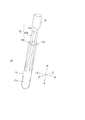
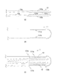
【課題】細胞単離に関する複数の工程(生体組織の把持、搬送、単離)をスムーズに行うことができる細胞単離容器を提供すること。【解決手段】容器11は、開口11bを有する。封止部材12は、開口11bを封止する。一対の挟持部13(13a、13b)は、封止部材12に接続され、押圧によって開閉可能に構成されている。【選択図】図1[Object] To provide a cell isolation container capable of smoothly performing a plurality of steps related to cell isolation (gripping, transporting, and isolation of a living tissue). A container 11 has an opening 11b. The sealing member 12 seals the opening 11b. A pair of clamping part 13 (13a, 13b) is connected to the sealing member 12, and is comprised so that opening and closing is possible by pressing. [Selection] Figure 1
Description
本発明は細胞単離器具に関し、特に生体組織から細胞を単離する細胞単離器具に関する。 The present invention relates to a cell isolation instrument, and more particularly to a cell isolation instrument for isolating cells from a living tissue.
医療機関において細胞検査士や病理医は、被験者から採取した細胞切片を用いて診断を行う。しかしながら凍結切片による標本は不完全となる場合も多い。また組織の一断面しか見ることのできない上述の診断では、判断が難しい症例もある。そこで被験者から採取した生体組織から細胞を単離し、当該細胞をフローサイトメータで解析を行う手法が用いられている。 In medical institutions, cytologists and pathologists make diagnoses using cell sections collected from subjects. However, specimens with frozen sections are often incomplete. In addition, there are cases in which it is difficult to make a judgment based on the above-mentioned diagnosis in which only one section of tissue can be seen. Therefore, a technique is used in which cells are isolated from a biological tissue collected from a subject and the cells are analyzed with a flow cytometer.
生体組織から細胞を単離する工程では、複数の工程を要すると共に、熟練した技術が必要となる。そのため、細胞単離を正確かつ迅速に行うための技術が求められている。特に消化器にかかる生体組織は硬度を有するため、当該生体組織から細胞単離を的確に行う必要がある。 In the process of isolating cells from a living tissue, a plurality of processes are required, and skillful techniques are required. Therefore, there is a need for a technique for accurately and quickly performing cell isolation. In particular, since the living tissue related to the digestive organ has hardness, it is necessary to accurately isolate cells from the living tissue.
特許文献1は、生体組織から細胞を単離する破砕処理装置を開示している。当該破砕処理装置は、容器に収容された生体組織に破砕部材を押し当てた状態で回転させることにより、生体組織から細胞を単離する。 Patent document 1 is disclosing the crushing processing apparatus which isolates a cell from a biological tissue. The crushing apparatus isolates cells from the living tissue by rotating the crushing member while pressing the crushing member against the living tissue contained in the container.
上述の特許文献1に記載の技術では、生体組織を容器内に入れる処理を行い、その後に生体組織に圧力を加えることにより細胞を単離している。このように、容器内に生体組織を配置した後に単離処理を行うため、複数の工程(生体組織の把持、搬送、単離)を連続してスムーズに行うことができないという問題があった。 In the technique described in Patent Document 1 described above, a process of placing a living tissue in a container is performed, and then cells are isolated by applying pressure to the living tissue. As described above, since the isolation process is performed after the living tissue is arranged in the container, there is a problem that a plurality of steps (gripping, transporting, and isolation of the living tissue) cannot be performed continuously and smoothly.
本発明は上述の課題に鑑みてなされたものであり、細胞単離に関する複数の工程(生体組織の把持、搬送、単離)をスムーズに行うことができる細胞単離器具を提供することを主たる目的とする。 This invention is made | formed in view of the above-mentioned subject, and mainly provides the cell isolation instrument which can perform the several process (gripping, conveyance, isolation of a biological tissue) regarding cell isolation smoothly. Objective.
本発明にかかる細胞単離器具の一態様は、
開口を有する容器と、
前記開口を封止する封止部材と、
前記封止部材に接続され、押圧によって開閉可能に構成された一対の挟持部と、
を備える、ものである。
One aspect of the cell isolation instrument according to the present invention is:
A container having an opening;
A sealing member for sealing the opening;
A pair of clamping parts connected to the sealing member and configured to be opened and closed by pressing;
It is provided.
生体組織を挟持する挟持部が封止部材に設けられている。封止部材は、開口を有する容器を封止する部材である。そのため医療従事者は、生体組織を挟持し(つまんで)、そのまま容器内に生体組織を配置して開口を封止することができる。また医療従事者は、生体組織を挟持する際に押圧をすることにより、生体組織から細胞を単離することができる。すなわち単離処理を行いながら容器内に生体組織を配置することができるため、生体組織の把持、搬送、単離を一連の流れでスムーズに行うことが可能となる。 A clamping part for clamping the living tissue is provided in the sealing member. The sealing member is a member that seals the container having an opening. Therefore, the medical worker can pinch (pinch) the living tissue, arrange the living tissue in the container as it is, and seal the opening. Moreover, the medical worker can isolate a cell from a biological tissue by pressing when pinching a biological tissue. That is, since the living tissue can be placed in the container while performing the isolation process, the living tissue can be gripped, transported, and isolated smoothly in a series of flows.
本発明は、細胞単離に関する複数の工程(生体組織の把持、搬送、単離)をスムーズに行うことができる。 The present invention can smoothly perform a plurality of steps relating to cell isolation (gripping, transporting, and isolation of living tissue).
<実施の形態1>
以下、図面を参照して本発明の実施の形態について説明する。なお各図面においては、各部材を認識可能な大きさとするために縮尺などを適宜変更している。
<Embodiment 1>
Embodiments of the present invention will be described below with reference to the drawings. In each drawing, the scale and the like are appropriately changed to make each member a recognizable size.
はじめに本実施の形態にかかる細胞単離器具10の構成について説明する。図1は、細胞単離器具10を示す。細胞単離器具10は、容器11、封止部材12、及び挟持部13を有する。
First, the configuration of the
容器11は、上端面11aに開口11bを有し、下端部が丸底の円筒状の部材である。
容器11は、透明であることが望ましく、中空の内部空間11cが視認可能であることが望ましい。内部空間11cは開口11bに連通している。容器11は、例えばガラス製の試験管等であってもよいが、押圧によりたわむ程度の柔らかさの素材により構成することがより好ましい。例えば容器11は、ポリプロピレンやポリエチレン等の合成樹脂により構成されることが好ましい。換言すると容器11は、0.1〜3GPa程度の弾性を有することが望ましい。
The
The
封止部材12は、容器11の開口11bを封止する部材である。封止部材12の外径は、容器11の開口11bの直径と略等しい。封止部材12が開口11bに挿入されることにより、封止部材12が容器11に固定される。封止部材12の開口11bへの挿入面には挟持部13が接続されている。
The sealing
封止部材12は、容器11を封止できる構成であれば任意の形状でよい。例えば容器11の内周面及び封止部材12の外周面に対応形状の溝を設けておき、封止部材12の溝を容器11の溝に合わせた状態で回転させることにより封止を行えばよい。また封止部材12を弾性部材(例えばゴム)によって構成し、封止部材12を容器11の開口11bに挿入することによって封止を行ってもよい。本実施の形態における封止とは、容器11を閉塞して気密状態にすることまでは必要でなく、封止部材12及び挟持部13を容器11内に配置(または固定)できる形態であればよい。
The sealing
挟持部13は、封止部材12の下端部(開口11bへの挿入面)に接続されている。挟持部13は、一対の部材(13a、13b)であり、後述するが生体組織を挟持して圧力を加える。挟持部13は、押圧しない状態(力を加えない状態)では先端(封止部材12との接続面と対向する方向)が開いた状態となり、短手方向の両側から押圧した場合(図3(E)を参照して後述する。)には先端が閉じる。挟持部13は、生体組織を挟持すると共に、生体組織を押し潰すように作用する。挟持部13による生体組織の押圧(換言すると生体組織からの細胞の単離)については図3を参照して後述する。
The
なお挟持部13の挟持面は、挟持部13の接続部分(換言すると封止部材12との接続部分)に比べて広い面積を持つことが望ましい。これにより確実に生体組織を挟持することができる。挟持面とは生体組織が挟持される箇所を示す。
The clamping surface of the
以下の説明では容器11の下端方向を−Y方向、上端方向(開口方向)を+Y方向、挟持部13の開閉方向をX方向(+X方向、−X方向)、挟持部13の開閉方向と直交する方向をZ方向(+Z方向、−Z方向)とする。
In the following description, the lower end direction of the
図2は、挟持部13(13a、13b)の先端部分の構成例を示す拡大図である。図2(A)の例では、挟持部13の挟持面131a及び131bが略平面形状となっている。図2(B)の例では、挟持部13の挟持面131c及び131dに凹凸が設けられた形状となっている。図2(C)の例では、挟持部13の挟持面131eがいわゆる剣山のような凹凸形状(先端が細く鋭利となっている柱状体が複数設けられているもの)となっている。図2(D)の例では、挟持部13の双方の挟持面131g及び挟持面131hがいわゆる剣山のような凹凸形状(先端が細く鋭利となっている柱状体が複数設けられているもの)となっている。挟持部13は、図2(A)〜図2(D)の形態のいずれであっても構わないものの、図2(B)〜図2(D)の形態では生体組織を挟持する挟持面(131c、131d、131e、131g、131h)に凹凸が設けられている。そのため図2(B)〜(D)の構成では、加える力がわずかなであっても生体組織を強力に押圧することができる。なお図2(B)〜(D)において挟持面の全面に凹凸があることがより好ましいが、挟持面の一部にのみ凹凸が設けられていてもよい。
FIG. 2 is an enlarged view showing a configuration example of the distal end portion of the sandwiching portion 13 (13a, 13b). In the example of FIG. 2A, the clamping
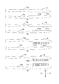
続いて図3を参照して、細胞単離器具10の使用方法について説明する。図3(A)は、生体組織tを挟持する前の状態を示す図である。なお以下の説明において挟持面の形状は上述の図2(B)と同様のものを想定して説明する。細胞単離器具10の使用前の段階において医療従事者は、封止部材12及び挟持部13を容器11から取り外しておく。上述したように一対の挟持部13(13a、13b)は、力を加えない状態では先端が離れた状態となる。
Subsequently, a method of using the
続いて生体組織tを挟持した状態を図3(B)に示す。前提として医療従事者は、被験者(人間のみならず動物も含む)から挟持できる程度の大きさの生体組織tを採取しておく。医療従事者は、生体組織tを挟持部13の先端で挟み込み、挟持部13の中間付近(挟持部13の先端と封止部材12との接続点の中間)を両側から押圧する。換言すると医療従事者は、生体組織tを挟持部13の先端に挟んだ状態とし、挟持部13aと挟持部13bの間が狭まる方向に圧力を加える。すなわち挟持部13aと挟持部13bは、押圧をするか否かにより開閉可能(好適には接離可能)に構成される。
Next, a state where the living tissue t is sandwiched is shown in FIG. As a premise, a medical worker collects a living tissue t that is large enough to be clamped from a subject (including not only humans but also animals). The medical worker inserts the biological tissue t with the tip of the sandwiching
図3(C)は、挟持部13に生体組織tを挟み込んで押圧した後の状態を示す概念図である。医療従事者は、上述のように生体組織tを挟持部13を介して潰すように力を加える(矢印方向に力を加える)。これにより生体組織tは、挟持前よりも潰れた状態となる。生体組織tは、潰れることにより柔らかくなり、その表面積が増加する。表面積が増加することにより生体組織tから細胞が離脱しやすくなる。このように生体組織tを潰すことにより、生体組織tから細胞が単離された状態(または単離しやすくなった状態)となる。
FIG. 3C is a conceptual diagram showing a state after the living tissue t is sandwiched and pressed in the sandwiching
医療従事者は、生体組織tを潰しながら挟持した状態で容器11に挟持部13を挿入する。当該状態を図3(D)に示す。医療従事者は、生体組織t及び挟持部13を容器11に挿入し、封止部材12を容器11の開口11b(当該図面には図示せず)に嵌め合わせる。これにより挟持によって潰された生体組織tが容器11内に配置された状態となる。
The medical worker inserts the clamping
なお医療従事者は、図示しないものの生体組織tを容器11内に挿入する前に、容器11に試薬(図示せず)及び細胞処理液(図示せず)を注入しておく。試薬とは、例えば界面活性剤、RNA(リボ核酸)除去剤、および蛍光染料色素を含むものであればよい。細胞処理液とは、例えばPBS(リン酸緩衝液)等の浸透圧が生体と略同一であるものが望ましい。
Note that a medical worker injects a reagent (not shown) and a cell treatment solution (not shown) into the
界面活性剤は、生体組織から単離された細胞の裸核化を行う。RNA除去剤は、溶液(単離された細胞を含む溶液)のRNAを除去する。また蛍光染料色素は、裸核化された細胞を染色する。これにより、細胞の単離と同時に、細胞の裸核化、RNA除去、細胞染色を行うことができる。 Surfactants perform naked nucleation of cells isolated from living tissue. The RNA removing agent removes RNA in a solution (a solution containing isolated cells). Fluorescent dye pigments stain cells that have become naked nuclei. As a result, cell nucleation, RNA removal, and cell staining can be performed simultaneously with cell isolation.
医療従事者は、容器11内に生体組織tを配置した後に、更に生体組織tに圧力を加えることにより細胞を単離する。図3(E)は、容器11内において生体組織tを単離する方法を示す図である。
After arranging the biological tissue t in the
上述のように容器11は、医療従事者の押圧によりたわむ程度の柔らかさ(押圧によって変形可能な柔らかさ)となっている。容器11のヤング率は、例えば0.1GPa〜3GPa程度であればよい。医療従事者は、容器11を潰すように圧力を加える。これにより容器11が変形し、圧力が生体組織tに加わる。ここで容器11のヤング率は、挟持部13のヤング率よりも小さいことが好ましい。このヤング率の関係(容器11のヤング率が小さい)により挟持部13がしっかりと生体組織tを挟持したまま、生体組織tに対して圧力を加えることができる。医療従事者は、容器11を介した生体組織tへの押圧と押圧解放を繰り返し行うことにより(換言すると図3(D)と図3(E)の状態を複数回往復することにより)、生体組織tから細胞を単離する。
As described above, the
なお医療従事者は、容器11に生体組織tを入れる前の段階(すなわち図3(C)の段階)で押圧と押圧解放を繰り返し行うことによって生体組織tからの細胞単離を実行してもよい。容器11を押圧変形しない固い形状によって構成する場合には、事前の押圧が必要な作業となる。
Note that the medical staff may perform isolation of cells from the biological tissue t by repeatedly performing pressing and releasing at the stage before putting the biological tissue t into the container 11 (ie, the stage of FIG. 3C). Good. In the case where the
医療従事者は、生体組織tから細胞を十分に単離できたと判断した場合、容器11から溶液(単離された細胞を含む溶液)を抽出して、フローサイトメータによる細胞の解析を行う。
When it is determined that the cells have been sufficiently isolated from the biological tissue t, the medical staff extracts the solution (the solution containing the isolated cells) from the
続いて本実施の形態にかかる細胞単離器具10の効果について説明する。上述のように生体組織を挟持する挟持部13が封止部材12に設けられている。封止部材12は、開口11bを封止する。そのため医療従事者は、生体組織を挟持し(つまんで)、そのまま容器11内に生体組織を配置することができる。また医療従事者は、生体組織を挟持する際に押圧をすることにより、生体組織の表面積を増加させ、生体組織から細胞を単離することができる。すなわち押圧をしながら容器11内に生体組織を配置することができるため、生体組織の把持、搬送、単離を一連の流れでスムーズに行うことが可能となる。
Then, the effect of the
また挟持部13は、挟持面を凹凸形状とすることができる(図2(B)〜図2(D))。凹凸を有することにより、挟持部13は医療従事者が加えた圧力が生体組織に加わる面積を大きくすることができる。これにより医療従事者が加えた圧力を効率よく生体組織に伝えることができ、生体組織から効率よく細胞を単離することができる。また挟持面が凹凸を有することにより、挟持面がすべり止めとしても作用し、搬送中に生体組織を落とす可能性を軽減できる。
Moreover, the clamping
また挟持部13は、医療従事者が押圧をしない状態では先端が開いた状態となっていることが好ましい(図1)。これにより医療従事者は、生体組織を指でつまむ動作と同等の動作で扱うことができる。
Moreover, it is preferable that the front-end | tip of the clamping
さらに容器11は、医療従事者が押圧することによって変形する程度の柔らかさであることが好ましい。例えば容器11のヤング率は、0.1〜3GPa程度であることが好ましい。これにより、医療従事者は容器11の外から生体組織を潰すこと(換言すると容器11を変形させて、容器11内の生体組織に圧力を加えること)ができる。
Furthermore, it is preferable that the
ここで容器11のヤング率よりも挟持部13のヤング率が高いことが望ましい。すなわち容器11よりも挟持部13の方が固い素材であることが好ましい。これにより容器11が押圧によって変形したとしても、挟持部13の変形が小さくなる。挟持部13の変形が小さいことにより、挟持部13がしっかりと生体組織を挟持した状態で、生体組織に対して圧力を加えることができる。
Here, it is desirable that the Young's modulus of the sandwiching
以上、本発明者によってなされた発明を実施の形態に基づき具体的に説明したが、本発明は既に述べた実施の形態に限定されるものではなく、その要旨を逸脱しない範囲において種々の変更が可能であることはいうまでもない。以下、変形例について説明する。 As mentioned above, the invention made by the present inventor has been specifically described based on the embodiments. However, the present invention is not limited to the embodiments already described, and various modifications can be made without departing from the scope of the invention. It goes without saying that it is possible. Hereinafter, modified examples will be described.
(変形例1)
上述の構成では、圧力を加えない状態では挟持部13の先端が開いた状態であることを説明したが、圧力を加えない状態では挟持部13の先端が閉じている構成であってもよい。この場合、圧力を加えることにより挟持部13の先端が開くこととなる。この場合であっても、生体組織の把持、搬送、単離をスムーズに行うことができる。
(Modification 1)
In the above-described configuration, it has been described that the tip of the clamping
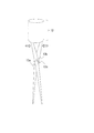
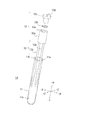
(変形例2)
上述した挟持部13の形状はあくまでも一例であり、その他の形状であっても構わない。挟持部13の変形例を図4に示す。当該変形例では、挟持部13aと挟持部13bが支点部材13cによって結合されている。医療従事者は、挟持部13と封止部材12の結合部分付近(例えば図4の矢印部分)を押圧すること及び押圧解放することにより、挟持部13aと挟持部13bの先端を開閉(接離)する。
(Modification 2)
The shape of the clamping
当該構成であっても挟持部13a及び挟持部13bの先端で生体組織を挟持できると共に、挟持の際に生体組織に圧力を加えて、生体組織から細胞を単離することができる。すなわち生体組織の把持、搬送、単離を合わせて行うことができ、医療従事者の作業効率を向上させることができる。
Even with this configuration, the biological tissue can be clamped at the tips of the
図4の構成においても挟持部13a及び挟持部13bの挟持面には凹凸(図2(B)〜図2(D))が設けられていてもよい。
Also in the configuration of FIG. 4, irregularities (FIGS. 2B to 2D) may be provided on the clamping surfaces of the clamping
なお図1及び図4の構成は、あくまでも一例であり、押圧により挟持部13の開閉状態を調整できる構成であれば、この他の形態であっても勿論構わない。
1 and 4 are merely examples, and other configurations may be used as long as the configuration can adjust the open / close state of the clamping
(変形例3)
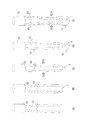
上述の説明では挟持部13の挟持面131で生体組織を挟んで押圧することを想定したが、容器11に生体組織を押し当てることによって細胞単離を行ってもよい。当該手法を用いる際の構成を図5に示す。
(Modification 3)
In the above description, it is assumed that the living tissue is sandwiched and pressed by the sandwiching surface 131 of the sandwiching
図5(A)は、容器11に生体組織を押し当てて細胞単離する際に用いる挟持部13の構成例を示す拡大図である。図示するように、挟持面131cに対向する対向面132aの一部に凹凸が設けられている。同様に挟持面131dに対向する対向面132bの一部に凹凸が設けられている。この対向面132a及び対向面132bは、挟持部13が開状態の場合(挟持部13aと挟持部13bが離れるように作用している場合)に容器11の内壁に押し当てられる。この際に容器11の内壁と対向面132a(または132b)との間に生体組織が挟まれることにより、細胞単離が行われる。なお図5(A)では、挟持面131c及び挟持面131dを凹凸のある形状としたが必ずしもこれに限られず、他の形状(例えば図2(A)〜図2(D)の任意の形態)であっても構わない。
FIG. 5A is an enlarged view showing a configuration example of the clamping
なお、容器11の内壁にも凹凸が設けられていることにより、より細胞単離を効率よく行うことも可能である。図5(B)は、容器11の内壁に凹凸を有する形状を示す。図示するように容器11の内壁面111a及び内壁面111bに凹凸が設けられている。
In addition, it is also possible to perform cell isolation more efficiently because the inner wall of the
図5(C)は、図5(A)に示す挟持部13と図5(B)に示す容器11を使用した細胞単離の概念を示す図である。図示するように生体組織t1は、内壁面111a及び対向面132aに挟まれる。挟まれて圧力がかかることにより、生体組織t1から細胞が単離する。同様に生体組織t2は、内壁面111b及び対向面132bに挟まれる。挟まれて圧力がかかることにより、生体組織t2から細胞が単離する。
FIG. 5 (C) is a diagram showing the concept of cell isolation using the holding
当該構成(図5(A)、図5(B))であっても、生体組織の把持、搬送、単離を合わせて行うことができる。 Even in this configuration (FIGS. 5A and 5B), the living tissue can be grasped, transported, and isolated together.
なお変形例4においても容器11は、上述のように医療従事者の押圧により変形する程度の柔らかさであることが好ましい。医療従事者が容器11に対して押圧を行うことにより、容器11の外側から生体組織t1やt2を内壁面111a及び内壁面111bに押し当てることができる。
In addition, also in the modified example 4, it is preferable that the
なお容器11の内壁面111a及び内壁面111bに凹凸がある形状(図5(B))は、任意の挟持部13の形状(例えば図2(A)〜図2(D)のように挟持面の対向面に凹凸が無い形状)と組み合せて使用することもできる。凹凸を有する内壁面111a及び内壁面111bに生体組織が接することにより、生体組織から細胞が単離されやすい状態となる。
In addition, the shape (FIG. 5B) in which the
なお図5(B)の例では、容器11の側面の内壁面111a及び内壁面111bに凹凸形状を設けたが、容器11の丸底面にも凹凸形状を設けても構わない。すなわち容器11の内壁の一部に凹凸がある形状であればどのような形状であっても構わない。
In the example of FIG. 5B, the concave and convex shapes are provided on the
(変形例4)
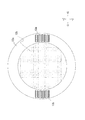
封止部材12には、フィルタが設けられていてもよい。当該構成例を図6及び図7を参照して説明する。図6は、細胞単離器具10の変形例にかかる分解図である。細胞単離器具10は、図1の構成と同様に容器11、封止部材12、及び挟持部13を有する。
(Modification 4)
The sealing
本変形例において封止部材12は、大径部12a、フィルタ12b、及び小径部12cを備える。大径部12aは、容器11の開口11bを封止する部材である。大径部12aの外径は、容器11の開口11bの直径と略等しい。大径部12aが開口11bに挿入されることにより、封止部材12が容器11に固定される。大径部12aの開口11bへの挿入面には挟持部13が接続されている。大径部12aには、容器11に入れられた溶液(単離された細胞を含む溶液)をフィルタ12bに連通する連通孔12eが設けられている。
In this modification, the sealing
フィルタ12bは、細胞毒性のない材料により形成され、単離された細胞(裸核化された細胞)を含む溶液が通過可能な程度の目開きを有する。例えばフィルタ12bは、目開50μmのナイロンメッシュである。フィルタ12bは、細胞を含む溶液を小径部12cに向かって通過させると共に、不要物が小径部12cへ流入することを禁止する。すなわちフィルタ12bは、容器11内の溶液をろ過する。
The
小径部12cは、フローサイトメータと接続し、フィルタ12bから供給された溶液(単離された細胞を含む溶液)をフローサイトメータに供給する。なお小径部12cは、フローサイトメータ以外の装置やシャーレ等の容器と接続してもよい。小径部12cには、フィルタ12bと小径部12cの上端面を連通する連通孔12dが設けられている。
The
図7は、−Y方向から挟持部13及び封止部材12を参照した場合の概念図である。図示するように大径部12aは、中央部がくり抜かれた円筒状の形状である。当該くり抜かれた部分が溶液の通過する連通孔12eを構成する。換言すると大径部12aは、高さを有するリング形状とも解釈できる。フィルタ12bは、大径部12aと小径部12c(図示せず)の間に配置される。
FIG. 7 is a conceptual diagram when the clamping
挟持部13a及び挟持部13bは、大径部12aの底面に接続される。例えば挟持部13a及び挟持部13bは、大径部12aの底面に融着されてもよく、大径部12aの嵌合口に嵌合されてもよく、大径部12aに螺合されてもよい。すなわち挟持部13a及び挟持部13bは、先端が開閉可能(好適には接離可能)に構成されるように大径部12aに接続されればよい。
The clamping
医療従事者は、図3に示す手順で生体組織から細胞を単離する。生体組織から細胞を十分に単離できたと判断した場合、容器11から溶液(単離された細胞を含む溶液)を抽出して、フローサイトメータによる細胞の解析を行う。例えば医療従事者は、封止部材12の連通孔12dが重力方向を向くように細胞単離器具10を把持する。これにより、重力方向に溶液が移動し、溶液を抽出することができる。なお異物は、フィルタ12bにより取り除かれる。抽出した溶液は、RNAの除去や細胞染色が終わった状態であるため、即座にフローサイトメータによる解析を行うことができる。なおフローサイトメータのノズルに連通孔12dを嵌め合わせた状態で細胞単離器具10から溶液を抽出することも可能である。
A medical worker isolates cells from the living tissue by the procedure shown in FIG. When it is determined that the cells have been sufficiently isolated from the biological tissue, the solution (solution containing the isolated cells) is extracted from the
上述の変形例(図6、図7)では封止部材12には連通孔12d及び連通孔12eが設けられていると共に、連通孔12dと容器11の間にフィルタ12bが設けられている。フィルタ12bは、溶液(単離された細胞を含む溶液)から不純物を取り除く。これにより、不純物の影響の少ない解析を行うことができる。
In the above-described modified examples (FIGS. 6 and 7), the sealing
10 細胞単離器具
11 容器
11a 上端面
11b 開口
11c 内部空間
12 封止部材
12a 大径部
12b フィルタ
12c 小径部
12d 連通孔
13(13a、13b) 挟持部
13c 支点部材
t 生体組織
DESCRIPTION OF
Claims (8)
前記開口を封止する封止部材と、
前記封止部材に接続され、押圧によって開閉可能に構成された一対の挟持部と、
を備える、細胞単離器具。 A container having an opening;
A sealing member for sealing the opening;
A pair of clamping parts connected to the sealing member and configured to be opened and closed by pressing;
A cell isolation instrument comprising:
Priority Applications (3)
| Application Number | Priority Date | Filing Date | Title |
|---|---|---|---|
| JP2016003181A JP6694714B2 (en) | 2016-01-12 | 2016-01-12 | Cell isolation instrument |
| EP16207519.6A EP3192450B1 (en) | 2016-01-12 | 2016-12-30 | Cell isolation instrument |
| US15/403,941 US11553904B2 (en) | 2016-01-12 | 2017-01-11 | Cell isolation instrument |
Applications Claiming Priority (1)
| Application Number | Priority Date | Filing Date | Title |
|---|---|---|---|
| JP2016003181A JP6694714B2 (en) | 2016-01-12 | 2016-01-12 | Cell isolation instrument |
Publications (2)
| Publication Number | Publication Date |
|---|---|
| JP2017123785A true JP2017123785A (en) | 2017-07-20 |
| JP6694714B2 JP6694714B2 (en) | 2020-05-20 |
Family
ID=57777465
Family Applications (1)
| Application Number | Title | Priority Date | Filing Date |
|---|---|---|---|
| JP2016003181A Expired - Fee Related JP6694714B2 (en) | 2016-01-12 | 2016-01-12 | Cell isolation instrument |
Country Status (3)
| Country | Link |
|---|---|
| US (1) | US11553904B2 (en) |
| EP (1) | EP3192450B1 (en) |
| JP (1) | JP6694714B2 (en) |
Families Citing this family (1)
| Publication number | Priority date | Publication date | Assignee | Title |
|---|---|---|---|---|
| DE102021200214A1 (en) | 2021-01-12 | 2022-07-14 | Anvajo GmbH | sample receiving device |
Citations (5)
| Publication number | Priority date | Publication date | Assignee | Title |
|---|---|---|---|---|
| JPH01136460U (en) * | 1988-03-10 | 1989-09-19 | ||
| JPH0344664U (en) * | 1989-09-07 | 1991-04-25 | ||
| JP2009036732A (en) * | 2007-08-03 | 2009-02-19 | Rohto Pharmaceut Co Ltd | Container for extraction |
| WO2010024042A1 (en) * | 2008-08-29 | 2010-03-04 | オリンパス株式会社 | Specimen container |
| US20110020860A1 (en) * | 2008-12-29 | 2011-01-27 | Greenwald Robert J | Fecal examination method and collection container |
Family Cites Families (12)
| Publication number | Priority date | Publication date | Assignee | Title |
|---|---|---|---|---|
| US3080760A (en) * | 1960-06-29 | 1963-03-12 | American Cyanamid Co | Disposable sample probe for bulk chemicals |
| USB420262I5 (en) * | 1967-04-24 | |||
| US3705018A (en) * | 1970-06-10 | 1972-12-05 | Billy W Taylor | Resealable test tube |
| US4690153A (en) * | 1985-11-29 | 1987-09-01 | Becton, Dickinson And Company | Flow inducing means for small volume containers |
| US4967763A (en) * | 1989-03-13 | 1990-11-06 | Becton, Dickinson And Company | Platelet stable blood collection assembly |
| US5269804A (en) * | 1991-04-04 | 1993-12-14 | Symbiosis Corporation | Endoscopic colo-rectal bowel clamp |
| US20050125013A1 (en) * | 2003-11-14 | 2005-06-09 | Alan Kessler | Safety surgical forceps |
| JP5297816B2 (en) * | 2007-01-26 | 2013-09-25 | オリンパスメディカルシステムズ株式会社 | Gripping device |
| JP2013255447A (en) * | 2012-06-12 | 2013-12-26 | Nippon Koden Corp | Cell isolation apparatus |
| US20130345596A1 (en) * | 2012-06-25 | 2013-12-26 | David S. Zimmon | Apparatus and methods for removing and collecting biopsy specimens from biopsy devices with fixation and preparation for histopathological processing or other analysis |
| JP5970293B2 (en) | 2012-08-21 | 2016-08-17 | シスメックス株式会社 | Crusher |
| US9839913B2 (en) * | 2014-07-14 | 2017-12-12 | Maria Lotosky-Compton | Medical specimen container |
-
2016
- 2016-01-12 JP JP2016003181A patent/JP6694714B2/en not_active Expired - Fee Related
- 2016-12-30 EP EP16207519.6A patent/EP3192450B1/en active Active
-
2017
- 2017-01-11 US US15/403,941 patent/US11553904B2/en active Active
Patent Citations (5)
| Publication number | Priority date | Publication date | Assignee | Title |
|---|---|---|---|---|
| JPH01136460U (en) * | 1988-03-10 | 1989-09-19 | ||
| JPH0344664U (en) * | 1989-09-07 | 1991-04-25 | ||
| JP2009036732A (en) * | 2007-08-03 | 2009-02-19 | Rohto Pharmaceut Co Ltd | Container for extraction |
| WO2010024042A1 (en) * | 2008-08-29 | 2010-03-04 | オリンパス株式会社 | Specimen container |
| US20110020860A1 (en) * | 2008-12-29 | 2011-01-27 | Greenwald Robert J | Fecal examination method and collection container |
Also Published As
| Publication number | Publication date |
|---|---|
| US20170196544A1 (en) | 2017-07-13 |
| US11553904B2 (en) | 2023-01-17 |
| JP6694714B2 (en) | 2020-05-20 |
| EP3192450A1 (en) | 2017-07-19 |
| EP3192450B1 (en) | 2021-08-18 |
Similar Documents
| Publication | Publication Date | Title |
|---|---|---|
| EP2741675B1 (en) | Device for the collection of biological samples, and corresponding method | |
| US9168029B2 (en) | Biological sample collection device | |
| CN105008917B (en) | Devices designed to receive biological samples | |
| CN1767897B (en) | Sample processing tubule | |
| TW201105971A (en) | Microfluidic device having onboard tissue or cell sample handling capability | |
| US20090030342A1 (en) | Apparatus and method for releasing a sample of material | |
| US8402846B2 (en) | Sample trituration vessel, tool and method using the same | |
| US7405071B2 (en) | Method and device for manipulating individual small objects | |
| US20150140655A1 (en) | Apparatus and methods for sperm separation | |
| US10150118B2 (en) | Controlled transfer biological sample collection devices and methods of using such devices | |
| KR101777169B1 (en) | Transport container for collecting sample | |
| US20210291181A1 (en) | Seal component for a rapid diagnostic test | |
| US20160157838A1 (en) | Controlled transfer biological sample collection devices and methods of using such devices | |
| JP2017123785A (en) | Cell isolation tool | |
| US9295453B2 (en) | Biological fluid collection and sampling container | |
| SA515360976B1 (en) | Devices and methods for testing the cleanliness of medical instruments | |
| JP4913732B2 (en) | Integrated analyzer that can be attached to a container that contains analysis samples | |
| US20230146816A1 (en) | Large area surface sampler with invertible bag | |
| WO2006082698A1 (en) | Vessel for section sample treatment, method of section sample treatment and section sample treatment apparatus | |
| EP3630355B1 (en) | Modified sample processing tubule | |
| WO2017087703A1 (en) | Sample processing and smearing apparatus and methods | |
| Jayasinghe et al. | Sterile and disposable fluidic subsystem suitable for clinical high speed fluorescence‐activated cell sorting | |
| US10908052B2 (en) | Venturi vacuum device for biological sample collections | |
| JP2001212205A (en) | Flexible sample container | |
| DE102022202860A1 (en) | Microfluidic device with a membrane for receiving a sample |
Legal Events
| Date | Code | Title | Description |
|---|---|---|---|
| A621 | Written request for application examination |
Free format text: JAPANESE INTERMEDIATE CODE: A621 Effective date: 20181203 |
|
| A131 | Notification of reasons for refusal |
Free format text: JAPANESE INTERMEDIATE CODE: A131 Effective date: 20191001 |
|
| A977 | Report on retrieval |
Free format text: JAPANESE INTERMEDIATE CODE: A971007 Effective date: 20190930 |
|
| A521 | Request for written amendment filed |
Free format text: JAPANESE INTERMEDIATE CODE: A523 Effective date: 20191105 |
|
| TRDD | Decision of grant or rejection written | ||
| A01 | Written decision to grant a patent or to grant a registration (utility model) |
Free format text: JAPANESE INTERMEDIATE CODE: A01 Effective date: 20200327 |
|
| A61 | First payment of annual fees (during grant procedure) |
Free format text: JAPANESE INTERMEDIATE CODE: A61 Effective date: 20200420 |
|
| R150 | Certificate of patent or registration of utility model |
Ref document number: 6694714 Country of ref document: JP Free format text: JAPANESE INTERMEDIATE CODE: R150 |
|
| R250 | Receipt of annual fees |
Free format text: JAPANESE INTERMEDIATE CODE: R250 |
|
| LAPS | Cancellation because of no payment of annual fees |