JP2017123749A - Power supply system and notification device of building - Google Patents
Power supply system and notification device of building Download PDFInfo
- Publication number
- JP2017123749A JP2017123749A JP2016002374A JP2016002374A JP2017123749A JP 2017123749 A JP2017123749 A JP 2017123749A JP 2016002374 A JP2016002374 A JP 2016002374A JP 2016002374 A JP2016002374 A JP 2016002374A JP 2017123749 A JP2017123749 A JP 2017123749A
- Authority
- JP
- Japan
- Prior art keywords
- power supply
- power
- branch circuit
- branch
- supplied
- Prior art date
- Legal status (The legal status is an assumption and is not a legal conclusion. Google has not performed a legal analysis and makes no representation as to the accuracy of the status listed.)
- Pending
Links
Images


Landscapes
- Stand-By Power Supply Arrangements (AREA)
- Distribution Board (AREA)
Abstract
Description
本発明は、建物の電力供給システム及び報知装置に関する。 The present invention relates to a building power supply system and a notification device.
一般に、住宅等の建物には、分電盤が設けられている。分電盤には、電力会社から送電線等を介して商用電力が供給され、その供給された商用電力が分電盤から建物内の各種電気負荷(家電装置、照明器具など)へと供給される。分電盤には複数の分岐回路が接続されており、これらの分岐回路を介して商用電力が分電盤から各電気負荷へと供給される。 Generally, a distribution board is provided in a building such as a house. The distribution board is supplied with commercial power from a power company through a transmission line, etc., and the supplied commercial power is supplied from the distribution board to various electric loads (home appliances, lighting equipment, etc.) in the building. The A plurality of branch circuits are connected to the distribution board, and commercial power is supplied from the distribution board to each electric load via these branch circuits.
近年、災害などによる停電時にも建物内で電力が使用できるよう、商用電源系統とは別の電源装置(以下、外部電源装置という)を用いて建物内の各種電気負荷に電力を供給する技術が提案されている(例えば特許文献1参照)。この場合、例えば、外部電源装置を分電盤の上流側に接続し、その接続した外部電源装置より分電盤(及び分岐回路)を介して各電気負荷に電力供給することが考えられる。なお、外部電源装置としては、自動車や小型発電機などを用いることが考えられる。 In recent years, there has been a technology for supplying power to various electrical loads in a building using a power supply device (hereinafter referred to as an external power supply device) that is different from the commercial power supply system so that the power can be used in the building even in the event of a power failure due to a disaster. It has been proposed (see, for example, Patent Document 1). In this case, for example, it is conceivable that an external power supply device is connected to the upstream side of the distribution board, and power is supplied from the connected external power supply apparatus to each electric load via the distribution board (and branch circuit). In addition, it is possible to use a motor vehicle, a small generator, etc. as an external power supply device.
ところで、外部電源装置の給電能力は商用電源の給電能力よりも小さいことが考えられる。そのため、外部電源装置から建物内の電気負荷へ電力供給する際には、外部電源装置の給電能力(給電容量)に対して電気負荷の電力需要(電力消費)が過多となるおそれがある。その場合、外部電源装置による給電が突然停止される等の不都合が生じるおそれがある。 By the way, it is conceivable that the power supply capability of the external power supply device is smaller than the power supply capability of the commercial power supply. Therefore, when power is supplied from the external power supply device to the electrical load in the building, there is a possibility that the power demand (power consumption) of the electrical load is excessive with respect to the power supply capability (power supply capacity) of the external power supply device. In that case, there is a possibility that inconveniences such as suddenly stopping power feeding by the external power supply device may occur.
そこで、外部電源装置からの給電時には、例えば使用頻度の高い電気負荷にのみ電力を供給するようにすることが考えられる。つまり、分電盤に接続された各分岐回路のうち、かかる電気負荷が接続された分岐回路にのみ電力を供給することが考えられる。その場合、外部電源装置の給電能力に対して電力需要が過多となる上述の問題を回避することが可能となる。 Therefore, when power is supplied from the external power supply device, for example, it is conceivable to supply power only to an electric load that is frequently used. That is, it can be considered that power is supplied only to the branch circuit to which the electrical load is connected among the branch circuits connected to the distribution board. In that case, it becomes possible to avoid the above-mentioned problem that the power demand is excessive with respect to the power supply capability of the external power supply device.
しかしながら、外部電源装置からの給電時に、使用頻度の高い電気負荷が接続された分岐回路を特定するのは困難と考えられる。 However, it is considered difficult to specify a branch circuit to which an electrical load that is frequently used is connected when power is supplied from an external power supply device.
本発明は、上記事情に鑑みてなされたものであり、停電時(商用電源からの給電不可時)に外部電源から給電を行うに際し、その給電を適正に行いつつ、給電が不意に停止される等の不都合が生じるのを抑制できる建物の電力供給システム及び報知装置を提供することを主たる目的とするものである。 The present invention has been made in view of the above circumstances, and when power is supplied from an external power source during a power failure (when power cannot be supplied from a commercial power supply), the power supply is unexpectedly stopped while properly supplying the power. The main object of the present invention is to provide a building power supply system and a notification device that can prevent such inconveniences.
上記課題を解決すべく、第1の発明の建物の電力供給システムは、商用電源とそれとは別の外部電源とに選択的に接続可能とされ、その接続された電源より電力が供給される分電盤と、前記分電盤に供給される電力を建物内の電気機器に分配供給する複数の分岐回路と、前記分電盤において前記分岐回路ごとに設けられ、それぞれが前記分岐回路を開閉操作可能な複数の分岐ブレーカと、を備える建物の電力供給システムであって、前記商用電源からの電力供給時に、前記分岐回路ごとに前記電気機器の電力消費量を計測する計測手段と、前記外部電源から電力供給するに際し、その外部電源の給電能力を取得する取得手段と、前記計測手段により計測された前記分岐回路ごとの前記電気機器の電力消費量と、前記取得手段により取得された前記外部電源の給電能力とに基づいて、前記外部電源からの電力を前記各分岐回路のうちいずれに供給するかを決定する決定手段と、前記決定手段により電力供給先として決定された前記分岐回路の前記分岐ブレーカがいずれであるのかを報知手段により報知する報知制御手段と、を備えることを特徴とする。 In order to solve the above problems, the building power supply system according to the first invention can be selectively connected to a commercial power source and an external power source different from the commercial power source, and power is supplied from the connected power source. An electrical panel, a plurality of branch circuits that distribute and supply electric power supplied to the distribution panel to electrical equipment in a building, and each branch circuit in the distribution panel, each of which opens and closes the branch circuit A power supply system for a building comprising a plurality of possible branch breakers, measuring means for measuring the power consumption of the electrical equipment for each branch circuit when power is supplied from the commercial power supply, and the external power supply When supplying power from, the acquisition means for acquiring the power supply capability of the external power supply, the power consumption of the electrical device for each branch circuit measured by the measurement means, and acquired by the acquisition means Determining means for determining which of the branch circuits to supply power from the external power supply based on the power supply capability of the external power supply; and the branch circuit determined as a power supply destination by the determining means And a notifying control means for notifying which of the branch breakers is a notifying means.
本発明によれば、商用電源からの電力供給時に計測された分岐回路ごとの電気機器の電力消費量と、取得手段により取得された外部電源の給電能力とに基づいて、外部電源からの電力を各分岐回路のうちいずれに供給するかが決定される。この場合、各電気機器の電力消費量が外部電源の給電能力を越えないように電力供給先の分岐回路を決定することができる。また、使用頻度(電力消費頻度)の高い電気機器に電力供給する分岐回路を優先して電力供給先として決定することができる。 According to the present invention, the electric power from the external power source is calculated based on the power consumption of the electrical equipment for each branch circuit measured when supplying power from the commercial power source and the power supply capability of the external power source acquired by the acquiring unit. Which of the branch circuits is to be supplied is determined. In this case, the branch circuit of the power supply destination can be determined so that the power consumption of each electric device does not exceed the power supply capability of the external power supply. In addition, it is possible to preferentially determine a branch circuit that supplies power to an electric device that is frequently used (power consumption frequency) as a power supply destination.
また、電力供給先として決定された分岐回路の分岐ブレーカがいずれであるかが報知手段により報知されるため、ユーザはその報知された分岐ブレーカについては閉状態とし、それ以外の分岐ブレーカについては開状態とすることで、上記決定された分岐回路にのみ外部電源からの電力が供給されるようにすることができる。これにより、外部電源からの給電に際し、その給電を適正に行いつつ、当該給電が不意に停止される等の不都合が生じるのを抑制することができる。 In addition, since the notification means notifies the branch breaker of the branch circuit determined as the power supply destination, the user closes the notified branch breaker and opens the other branch breakers. By setting the state, it is possible to supply power from the external power source only to the determined branch circuit. As a result, when power is supplied from the external power supply, it is possible to suppress the occurrence of inconvenience such as unexpected stop of the power supply while appropriately performing the power supply.
第2の発明の建物の電力供給システムは、第1の発明において、前記報知手段は、前記分岐ブレーカごとに設けられた複数の発光部であり、前記報知制御手段は、報知処理として、前記決定手段により電力供給先として決定された前記分岐回路の分岐ブレーカに対応する前記発光部を発光させることを特徴とする。 In the building power supply system according to a second aspect of the present invention, in the first aspect, the notification means is a plurality of light emitting units provided for each of the branch breakers, and the notification control means determines the determination as the notification processing. The light emitting unit corresponding to the branch breaker of the branch circuit determined by the means as the power supply destination is caused to emit light.
本発明によれば、各分岐ブレーカごとに発光部が設けられている。そして、決定手段により電力供給先の分岐回路が決定されると、その決定された分岐回路の分岐ブレーカがいずれであるのかが当該ブレーカに対応する発光部が発光することで報知される。この場合、いずれの分岐ブレーカを閉状態とするのか開状態とするのかを容易に判別することが可能となる。 According to this invention, the light emission part is provided for every branch breaker. Then, when the branch circuit of the power supply destination is determined by the determining means, the branch circuit breaker of the determined branch circuit is notified by the light emitting unit corresponding to the circuit breaker emitting light. In this case, it is possible to easily determine which branch breaker is to be closed or opened.
第3の発明の建物の電力供給システムは、第1の発明において、前記報知手段は、前記分岐ブレーカごとに設けられた複数の発光部であり、前記報知制御手段は、報知処理として、前記決定手段により電力供給先として決定された前記分岐回路の分岐ブレーカに対応する前記発光部とそれ以外の前記発光部とで互いに発光態様が異なるように、各発光部を発光させることを特徴とする。 In a building power supply system according to a third aspect of the present invention, in the first aspect, the notification means is a plurality of light emitting units provided for each of the branch breakers, and the notification control means determines the determination as the notification processing. Each light emitting part is caused to emit light such that the light emitting part corresponding to the branch breaker of the branch circuit determined as a power supply destination by the means and the other light emitting parts have different light emission modes.
本発明によれば、電力供給先として決定された分岐回路の分岐ブレーカがいずれであるのかを報知するに際し、当該分岐ブレーカに対応する発光部とそれ以外の発光部とで互いに発光態様が異なるように各発光部が発光される。この場合にも、発光態様の違いで、いずれの分岐ブレーカを閉状態とするのか開状態とするのかを容易に判別することが可能となる。 According to the present invention, when informing which branch breaker of the branch circuit determined as the power supply destination is, the light emission mode is different between the light emitting unit corresponding to the branch breaker and the other light emitting units. Each light emitting part emits light. Also in this case, it is possible to easily determine which branch breaker is in the closed state or in the open state due to the difference in the light emission mode.
第4の発明の建物の電力供給システムは、第1乃至第3の発明において、前記計測手段により計測された前記分岐回路ごとの前記電気機器の電力消費量に基づき、前記分岐回路ごとに前記電気機器の使用頻度を判定する使用頻度判定手段を備え、前記決定手段は、前記使用頻度判定手段により判定された前記分岐回路ごとの電気機器の使用頻度に基づいて、前記外部電源からの電力をいずれの分岐回路に供給するかを決定することを特徴とする。 The building power supply system according to a fourth aspect of the present invention is the power supply system for buildings according to the first to third aspects of the invention, based on the power consumption of the electrical equipment for each branch circuit measured by the measuring means. Use frequency determining means for determining the frequency of use of the device, wherein the determining means determines the power from the external power source based on the frequency of use of the electrical device for each branch circuit determined by the use frequency determining means. It is characterized by determining whether to supply to the branch circuit.
本発明によれば、分岐回路ごとの電気機器の電力消費量に基づき分岐回路ごとの電気機器の使用頻度が判定され、その判定された分岐回路ごとの電気機器の使用頻度に基づいて、外部電源からの電力をいずれの分岐回路に供給するかが決定される。この場合、使用頻度の高い電気機器へ電力供給する分岐回路を優先して外部電源からの電力供給先として決定することができる。そのため、使用頻度の高い電気機器の使用を確保することができ、非常時にも比較的不都合なく過ごすことができる。 According to the present invention, the usage frequency of the electrical device for each branch circuit is determined based on the power consumption of the electrical device for each branch circuit, and the external power source is determined based on the determined usage frequency of the electrical device for each branch circuit. To which branch circuit the power from is supplied. In this case, it is possible to preferentially determine the branch circuit that supplies power to the frequently used electrical device as the power supply destination from the external power source. For this reason, it is possible to ensure the use of frequently used electrical equipment, and it is possible to spend a relatively inconvenience in an emergency.
第5の発明の建物の電力供給システムは、第4の発明において、1日が複数の時間帯に分割されており、前記使用頻度判定手段は、今現在の時間帯における前記分岐回路ごとの前記電気機器の使用頻度を判定するものであり、前記決定手段は、前記判定された今現在の時間帯における分岐回路ごとの電気機器の使用頻度に基づいて、前記外部電源からの電力をいずれの分岐回路に供給するかを決定することを特徴とする。 The building power supply system according to a fifth aspect of the present invention is that, in the fourth aspect of the invention, one day is divided into a plurality of time zones, and the usage frequency determining means Determining the frequency of use of the electrical equipment, wherein the determining means branches any power from the external power source based on the frequency of use of the electrical equipment for each branch circuit in the determined current time zone. It is characterized by determining whether to supply to a circuit.
ところで、電気機器の利用頻度は1日の時間帯によって異なることが考えられる。例えば、昼間の時間帯には空調機器がよく用いられたり、夜間の時間帯には照明機器がよく用いられたりする。そこで本発明では、この点に鑑み、現在の時間帯における電気機器の使用頻度に基づいて、外部電源からの電力をいずれの分岐回路に供給するか決定している。この場合、現在の時間帯が夜間時間帯である場合には、その夜間時間帯に使用頻度の高い照明機器用の分岐回路を優先して電力供給先とする等、時間帯ごとの電気機器の使用状況を考慮して電力供給先の分岐回路を決定することができる。 By the way, it is conceivable that the frequency of use of electrical equipment varies depending on the time of day. For example, air conditioning equipment is often used during daytime hours, and lighting equipment is often used during nighttime hours. In view of this point, the present invention determines which branch circuit the power from the external power supply is supplied to based on the frequency of use of the electrical device in the current time zone. In this case, if the current time zone is a night time zone, the branch circuit for lighting equipment that is frequently used during that night time zone will be given priority as the power supply destination. The branch circuit of the power supply destination can be determined in consideration of the usage situation.
第6の発明の建物の電力供給システムは、第1乃至第5のいずれかの発明において、現在の季節を判定する季節判定手段を備え、前記決定手段は、前記季節判定手段により判定された現在の季節に基づいて、前記外部電源からの電力をいずれの分岐回路に供給するかを決定することを特徴とする。 A building power supply system according to a sixth aspect of the present invention includes, in any one of the first to fifth aspects, a season determination unit that determines a current season, wherein the determination unit is a current level determined by the season determination unit. Based on the season, it is determined to which branch circuit the power from the external power source is supplied.
ところで、夏場や冬場には電気機器として空調機器(冷暖房機器)が使用される頻度が高くなると考えられる。そこで本発明では、その点に鑑み、現在の季節に基づいて、外部電源からの電力をいずれの分岐回路に供給するかを決定している。この場合、例えば、現在の季節が夏場や冬場である場合には、空調機器が接続された分岐回路(空調用回路)を優先して外部電源からの電力供給先として決定することができる。これにより、夏場や冬場において空調機器の使用を確保できるため、非常時にも快適に過ごすことが可能となる。 By the way, it is thought that the frequency with which an air-conditioning apparatus (air-conditioning apparatus) is used as an electric device in summer and winter increases. In view of this point, the present invention determines which branch circuit the power from the external power supply is supplied to based on the current season. In this case, for example, when the current season is summer or winter, the branch circuit (air conditioning circuit) to which the air conditioner is connected can be preferentially determined as the power supply destination from the external power source. As a result, the use of air-conditioning equipment can be ensured in summer and winter, so that it is possible to spend comfortably in an emergency.
第7の発明の報知装置は、商用電源とそれとは別の外部電源とに選択的に接続可能とされ、その接続された電源より電力が供給される分電盤と、前記分電盤に供給される電力を建物内の電気機器に分配供給する複数の分岐回路と、前記分電盤において前記分岐回路ごとに設けられ、それぞれが前記分岐回路を開閉操作可能な複数の分岐ブレーカと、を備える建物に適用され、持ち運び可能に構成された装置本体と、前記各分岐回路にそれぞれ着脱可能に取り付けられる複数の計測手段と、前記分電盤において前記各分岐ブレーカの周辺にそれぞれ着脱可能に設けられる複数の発光部とを備え、前記複数の計測手段は、前記商用電源からの電力供給時に、前記分岐回路ごとの前記電気機器の電力消費量を計測するものであり、前記装置本体は、前記外部電源の給電能力を入力操作するための操作部と、前記操作部による入力操作に基づき、前記外部電源の給電能力を取得する取得手段と、前記各計測手段により計測された前記分岐回路ごとの前記電気機器の電力消費量と、前記取得手段により取得された前記外部電源の給電能力とに基づいて、前記外部電源からの電力供給時に、その電力を前記各分岐回路のうちいずれに供給するかを決定する決定手段と、前記決定手段により電力供給先として決定された前記分岐回路の分岐ブレーカに対応する前記発光部を発光させることで、当該分岐ブレーカがいずれであるのかを報知する報知制御手段と、を有することを特徴とする。 According to a seventh aspect of the present invention, there is provided a notification device capable of being selectively connected to a commercial power supply and an external power supply different from the commercial power supply, and a power distribution board supplied with power from the connected power supply, and supplying the power distribution board A plurality of branch circuits that distribute the power to be distributed to the electrical equipment in the building, and a plurality of branch breakers that are provided for each of the branch circuits in the distribution board and that can open and close the branch circuits, respectively. An apparatus main body applied to a building and configured to be portable, a plurality of measuring means detachably attached to each branch circuit, and detachably provided around each branch breaker in the distribution board A plurality of light emitting units, and the plurality of measuring means measure power consumption of the electric device for each branch circuit when power is supplied from the commercial power source. For each branch circuit measured by each measuring means, an operating section for performing an input operation of the power feeding capacity of the external power supply, an acquisition means for obtaining the power feeding capacity of the external power supply based on an input operation by the operating section Based on the power consumption of the electrical device and the power supply capability of the external power source acquired by the acquiring unit, the power is supplied to any of the branch circuits when power is supplied from the external power source. And a notification control for notifying which branch breaker is caused by causing the light emitting unit corresponding to the branch breaker of the branch circuit determined as a power supply destination to emit light. And means.
本発明の報知装置によれば、その装置本体が持ち運び可能に構成され、計測手段と発光部とがそれぞれ着脱可能に構成されている。この場合、既設の建物に報知装置を持ち込んで、計測手段及び発光部を分岐回路等に取り付けることで、上述した第2の発明と同様の電力供給システムを構築することができる。これにより、既設の建物に対しても比較的容易に電力供給システムを構築することができる。 According to the notification device of the present invention, the device main body is configured to be portable, and the measuring means and the light emitting unit are configured to be detachable. In this case, a power supply system similar to that of the above-described second invention can be constructed by bringing a notification device into an existing building and attaching the measuring means and the light emitting unit to a branch circuit or the like. Thereby, it is possible to construct a power supply system relatively easily even for an existing building.
また、既設の建物に対してリフォーム等により、外部電源からの給電を可能とするシステムが事後的に導入される場合があるが、そのような場合にも、そのシステム導入時に本発明の報知装置を建物に持ち込んで電力供給システムを構築することが可能となる。 In addition, a system that enables power supply from an external power source may be introduced later by renovating an existing building. Even in such a case, the notification device of the present invention is used when the system is introduced. Can be brought into the building to construct a power supply system.
以下に、本発明を具体化した一実施の形態について図面を参照しつつ説明する。なお、図1は給電システムの電気的構成を示す図である。 Hereinafter, an embodiment of the present invention will be described with reference to the drawings. FIG. 1 is a diagram showing an electrical configuration of the power feeding system.
図1に示すように、建物10には、商用電源11から商用電力が供給されるようになっている。商用電源11は、発電所や送電設備、配電設備などを含んで構成され、電力会社等の事業者が住人等の電力消費者に系統電力等の商用電力を供給する設備となっている。建物10には、その商用電源11と送電線12を介して接続された電力メータ13と、その電力メータ13と電力線14を介して接続された切替装置15と、その切替装置15と電力線16を介して接続された分電盤20とが設けられている。これにより、商用電源11から商用電力が送電線12や電力線14,16等を介して分電盤20に供給され、ひいては分電盤20から建物10内の電気機器Lに供給されるようになっている。
As shown in FIG. 1, commercial power is supplied to a
切替装置15は、分電盤20(ひいては建物10内の電気機器L)に供給される電力の供給元を切り替えるものである。本実施形態の建物10では、災害等により停電が生じた場合に、建物10に非常用電源として外部電源装置17を接続し、その接続状態で外部電源装置17より建物10に電力を供給することが可能となっている。そして、この外部電源装置17が建物10に接続された場合に、分電盤20に電力を供給する供給元を商用電源11から外部電源装置17に、切替装置15により切り替えることが可能となっている。
The switching
本実施形態では、外部電源装置17として、外部給電機能を有する自動車を想定しており、詳しくは車載バッテリを搭載したハイブリッド自動車(PHV)を想定している。したがって、建物10の停電時には、そのハイブリッド自動車(詳しくは車載バッテリ)を建物10に接続し、そのハイブリッド自動車から建物10に電力を供給する。
In the present embodiment, an automobile having an external power feeding function is assumed as the external
外部電源装置17は、給電ケーブル25を介して建物10に接続可能とされている。給電ケーブル25は、その両端部に一対のコネクタ25a,25bを有している。それら各コネクタ25a,25bのうち一方のコネクタ25aが外部電源装置17(ハイブリッド自動車)に設けられた接続口(図示略)に接続され、他方のコネクタ25bが建物10に設けられた接続プラグ26に接続されることで、外部電源装置17が建物10(詳しくは接続プラグ26)に接続されるようになっている。
The external
接続プラグ26は電力線27を介して切替装置15と接続されている。したがって、外部電源装置17が給電ケーブル25を介して接続プラグ26に接続された状態では、外部電源装置17から電力(外部電力)が給電ケーブル25及び電力線27を介して切替装置15に供給される。切替装置15は、手動操作により、電力線14と電力線16とを接続する第1位置(通常位置)と、電力線27と電力線16とを接続する第2位置(非常時位置)とに位置切替可能となっている。切替装置15が第2位置に切り替えられると、外部電源装置17からの電力が給電ケーブル25及び電力線16,27を介して分電盤20に供給され、ひいては建物10内の各電気機器Lに供給される。
The connection plug 26 is connected to the
分電盤20は、主幹ブレーカ21と、複数の分岐ブレーカ22とを有している。主幹ブレーカ21は電力線16を介して切替装置15と接続されている。主幹ブレーカ21には、切替装置15を経由して商用電源11及び外部電源装置17のいずれかより電力が供給される。主幹ブレーカ21は、その供給される電力が予め規定された規定容量を越えた場合に、それよりも下流側への電力の供給を遮断する。
The
主幹ブレーカ21の下流側には複数の分岐電力線28が接続されている。これら複数の分岐電力線28はそれぞれ建物10内の電気機器(電気負荷)Lと接続されている。商用電源11又は外部電源装置17より分電盤20(主幹ブレーカ21)に電力が供給されると、その電力はこれらの分岐電力線28を介して各電気機器Lに供給される。そして、その供給される電力によって各電気機器Lが作動する。なお、電気機器Lとしては、照明機器や空調機器、家電機器等が挙げられる。
A plurality of
ここで、各分岐電力線28はそれぞれ分岐回路に相当するものであり、以下においてはこれらの分岐電力線28をそれぞれ分岐回路28と称することとする。分岐回路28としては、照明機器が接続された照明用回路や、冷暖房機能を有する空調機器(エアコン)が接続された空調用回路、リビングに設けられた各家電機器が接続されたリビング用回路等が設けられている。
Here, each
分岐ブレーカ22は各分岐回路28ごとに設けられている。各分岐ブレーカ22はそれぞれ(対応する)分岐回路28を手動操作により開閉可能となっている。分岐ブレーカ22が閉状態(ON状態)とされている場合には、主幹ブレーカ21(ひいては分電盤20)に供給された電力が分岐回路28を通じて電気機器Lに供給される一方、分岐ブレーカ22が開状態(OFF状態)とされている場合には、分岐回路28を通じた電気機器Lへの電力供給が遮断(禁止)される。また、分岐ブレーカ22は上下二列に配置され、上側及び下側の各列に分岐ブレーカ22が横並びで複数ずつ配置されている。
A
ここで、外部電源装置17の給電能力は商用電源11の給電能力と比べると小さいことが考えられる。そのため、外部電源装置17を用いて建物10内の各電気機器Lに電力を供給する場合、外部電源装置17の給電能力に対して各電気機器Lの電力消費が過多となる場合が想定され、その場合外部電源装置17による給電が突然停止される等の不都合が生じるおそれがある。そこで、本給電システムでは、外部電源装置17による給電時にかかる不都合が生じるのを回避すべく、特徴的な構成を設けている。以下においては、その特徴的な構成について説明する。
Here, it is conceivable that the power supply capability of the external
建物10には、各分岐回路28ごとに電力センサ31が設けられている。電力センサ31は、分岐回路28を通じて電気機器Lに供給される電力を計測するものである。分岐回路28を通じて電気機器Lに供給される電力は電気機器Lにて消費されるため、この場合、分岐回路28における電気機器Lの電力消費量が電力センサ31により計測されることになる。したがって、これら各電力センサ31により、分岐回路28ごとに電気機器Lの電力消費量が計測されるようになっている。なお、各電力センサ31がそれぞれ計測手段に相当する。
In the
各電力センサ31はそれぞれ分電盤20に設けられている。各電力センサ31はそれぞれ、測定対象となる分岐回路28の分岐ブレーカ22に隣接させて設けられている。詳しくは、上下二列に配置された分岐ブレーカ22のうち、上側の列に配置された分岐ブレーカ22にはその上方に隣接して電力センサ31が配置され、下側の列に配置された分岐ブレーカ22にはその下方に隣接して電力センサ31が配置されている。
Each
分電盤20には、各分岐ブレーカ22ごとに表示器32が設けられている。表示器32は、LED(発光ダイオード)等からなる発光表示灯である。本実施形態では、表示器32が電力センサ31と一体に設けられ、その電力センサ31が有するバッテリの電力で発光するものとなっている。なお、各表示器32がそれぞれ発光部に相当する。また、それら各表示器32により報知手段が構成されている。
The
各表示器32はそれぞれ分岐ブレーカ22に隣接させて設けられている。本実施形態では、表示器32が電力センサ31と一体に設けられているため、上側の列に配置された分岐ブレーカ22にはその上方に隣接して表示器32が配置され、下側の列に配置された分岐ブレーカ22にはその下方に隣接して表示器32が配置されている。
Each
なお、表示器32は必ずしも電力センサ31と一体で設ける必要はなく、別体で設けてもよい。また、各表示器32の配置態様は必ずしも上記の態様に限定されず、例えば、上側及び下側の各列に配置されたそれぞれの分岐ブレーカ22に対してその上方に隣接させて表示器32を配置してもよいし、またその下方に隣接させて表示器32を配置してもよい。さらに、各分岐ブレーカ22の上下に隣接させることに代え、各分岐ブレーカ22の左右いずれかに隣接させて表示器32を配置してもよい。要するに、各表示器32がいずれの分岐ブレーカ22に対応させて配置されているかがわかれば、その配置態様は任意でよい。
The
建物10には、本給電システムを管理する管理サーバ35が設けられている。管理サーバ35は、コントローラ36と、操作部37とを備える。コントローラ36は、CPU等を有する周知のマイクロコンピュータにより構成され、記憶部36aを有している。操作部37は、キーボード等を含んで構成され、コントローラ36と接続されている。
The
コントローラ36には、各電力センサ31が接続されている。コントローラ36には、これら各電力センサ31より各分岐回路28における電気機器Lの電力消費量が入力される。本実施形態では、商用電源11から建物10内の各電気機器Lに電力(商用電力)が供給される商用電力供給時に、これら各電力センサ31より逐次コントローラ36に各分岐回路28における電気機器Lの電力消費量が入力されるようになっている。そして、コントローラ36は、それら入力される分岐回路28ごとの電気機器Lの電力消費量を都度記憶部36aに記憶する。詳しくは、コントローラ36は、分岐回路28ごとの電力消費量を、その電力が消費された時間帯(時刻)と対応付けて記憶部36aに記憶する。これにより、記憶部36aには、各分岐回路28ごとの電気機器Lの電力消費量が時系列的に電力消費履歴として記憶される。
Each
コントローラ36には、各表示器32が接続されている。コントローラ36は、記憶部36aに記憶された各分岐回路28ごとの電力消費履歴等に基づいて、各表示器32を発光制御する。なお、図1では便宜上、コントローラ36から各表示器32への信号線を、各電力センサ31からコントローラ36への信号線と共通の信号線で示している。
Each
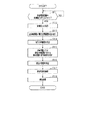
次に、停電時に外部電源装置17を用いて建物10(電気機器L)に電力を供給する際、その電力供給に先立ち、コントローラ36により実行される給電前制御処理について説明する。図2は、その給電前制御処理を示すフローチャートである。なお、本処理は、ユーザにより操作部37による開始操作が行われたことをトリガとして開始される。また、本処理を開始させるに先立ち、外部電源装置17を予め建物10側に接続しておく。
Next, when power is supplied to the building 10 (electric equipment L) using the external
図2に示すように、まずステップS11では、ユーザにより外部電源装置17の給電能力(定格出力)が操作部37により入力操作されたか否かを判定する。具体的には、管理サーバ35の表示ディスプレイに外部電源装置17の給電能力について入力を要求する入力要求画面を表示させ、その表示に基づいてユーザにより外部電源装置17の給電能力が入力されたか否かを判定する。外部電源装置17の給電能力が入力されていない場合には、入力されるまで本ステップの判定を繰り返す。一方、外部電源装置17の給電能力が入力された場合には、その入力された給電能力を取得する(ステップS12)。
As shown in FIG. 2, first, in step S <b> 11, it is determined whether or not an input operation of the power supply capability (rated output) of the external
ステップS13では、記憶部36aより各分岐回路28の電力消費履歴を読み出す(取得する)。
In step S13, the power consumption history of each
ステップS14では、今現在の時間帯を判定する。ここでは、1日が複数の時間帯に分割されており、具体的には昼間時間帯と夜間時間帯とに分割されている。したがって、本ステップでは、今現在の時間帯が昼間時間帯と夜間時間帯とのいずれであるかを判定する。この場合、例えば、コントローラ36に内蔵のタイマより現在の日時情報を取得し、その取得した日時情報に基づき今現在が昼間時間帯か夜間時間帯かを判定(取得)することが考えられる。
In step S14, the current time zone is determined. Here, one day is divided into a plurality of time zones, specifically, divided into a daytime time zone and a night time zone. Therefore, in this step, it is determined whether the current time zone is a daytime zone or a nighttime zone. In this case, for example, it is conceivable that the current date and time information is acquired from a timer built in the
ステップS15では、ステップS13で読み出した各分岐回路28の電力消費履歴に基づいて、各分岐回路28ごとに電気機器Lの使用頻度を判定する。具体的には、今現在の時間帯における分岐回路28ごとの電気機器Lの使用頻度を判定する。例えば、分岐回路28ごとの電気機器Lの使用頻度は、分岐回路28ごとの電気機器Lの電力消費時間に基づいて判定することが考えられる。
In step S15, based on the power consumption history of each
ステップS16では、今現在の季節を判定する。例えば、上述した内蔵タイマより現在の日時情報を取得し、その取得した日時情報に基づいて、今現在の季節が春期、夏期、秋期及び冬季のうちいずれであるかを判定する。 In step S16, the current season is determined. For example, the current date / time information is acquired from the above-described built-in timer, and based on the acquired date / time information, it is determined whether the current season is spring, summer, autumn, or winter.
ステップS17では、外部電源装置17からの電力を各分岐回路28のうちいずれの分岐回路28に供給するかを決定する供給先決定処理を行う。この処理では、ステップS12で取得した外部電源装置17の給電能力と、ステップS13で取得した分岐回路28ごとの電気機器Lの電力消費履歴と、ステップS15で判定した分岐回路28ごとの電気機器Lの使用頻度と、ステップS16で判定した今現在の季節とに基づいて、電力供給先となる分岐回路28を決定する。この決定処理に際しては、例えば以下の(a)〜(c)に示す各処理を行う。
In step S <b> 17, supply destination determination processing for determining which of the
(a)まず、外部電源装置17の給電能力と、分岐回路28ごとの電気機器Lの電力消費履歴(電力消費量)とに基づいて、各電気機器Lの電力消費量が外部電源装置17の給電能力を超えないように、電力供給先の分岐回路28を決定することが考えられる。
(A) First, based on the power supply capability of the external
(b)また、分岐回路28ごとの電気機器Lの使用頻度に基づき、使用頻度の高い電気機器Lが接続された分岐回路28を優先して電力供給先として決定することが考えられる。具体的には、今現在の時間帯における分岐回路28ごとの電気機器Lの使用頻度に基づき、今現在の時間帯において使用頻度の高い電気機器Lが接続された分岐回路28を優先して電力供給先として決定することが考えられる。例えば、今現在の時間帯が昼間時間帯である場合には、昼間時間帯において使用頻度の高い空調機器用の分岐回路28(空調用回路)を優先して電力供給先とすることが考えられる。また、今現在の時間帯が夜間時間帯である場合には、夜間時間帯において使用頻度の高い照明機器用の分岐回路28(照明用回路)を優先して電力供給先とすることが考えられる。
(B) Moreover, based on the usage frequency of the electric equipment L for every
(c)今現在の季節が夏期又は冬季である場合には、空調用回路を優先して電力供給先として決定することが考えられる。 (C) If the current season is summer or winter, it may be possible to prioritize the air conditioning circuit as the power supply destination.
ステップS18では、ステップS17で電力供給先として決定された分岐回路28の分岐ブレーカ22がいずれであるのかを報知する報知処理を行う。この報知処理では、かかる報知を、電力供給先として決定された分岐回路28の分岐ブレーカ22に対応する表示器32を点灯(発光)させることにより行う。この報知処理の後、本処理を終了する。
In step S18, a notification process for notifying which of the
上記報知処理により、ユーザはその報知された分岐ブレーカ22を閉状態(ON状態)とし、それ以外の分岐ブレーカ22を開状態(OFF状態)とすることで、電力供給先として決定された分岐回路28にのみ外部電源装置17からの電力を供給させることが可能となる。そして、上記のように各分岐ブレーカ22を開閉操作した後、ユーザは切替装置15を第1位置から第2位置に切替操作する。これにより、外部電源装置17から電力が分電盤20を介して電力供給先の各分岐回路28に供給される。詳しくは、外部電源装置17からの電力が電力供給先として決定された分岐回路28にのみ供給され、それ以外の分岐回路28には供給されない。
By the notification process, the user sets the notified
以上、詳述した本実施形態の構成によれば、以下の優れた効果が得られる。 As mentioned above, according to the structure of this embodiment explained in full detail, the following outstanding effects are acquired.
商用電源11からの電力供給時に電力センサ31により計測した分岐回路28ごとの電気機器Lの電力消費量(詳しくは電力消費履歴)と、操作部37の入力操作に基づき取得した外部電源装置17の給電能力とに基づき、外部電源装置17からの電力を各分岐回路28のうちいずれの分岐回路28に供給するかを決定した。この場合、各電気機器Lの電力消費量が外部電源装置17の給電能力を越えないように電力供給先の分岐回路28を決定できる。また、使用頻度(電力消費頻度)の高い電気機器Lに接続された分岐回路28を優先して電力供給先として決定できる。
The power consumption (specifically, power consumption history) of the electric device L for each
また、電力供給先として決定された分岐回路28の分岐ブレーカ22がいずれであるかが報知手段(具体的には複数の表示器32)により報知されるため、ユーザはその報知された分岐ブレーカ22については閉状態とし、それ以外の分岐ブレーカ22については開状態とすることで、上記決定された分岐回路28にのみ外部電源装置17からの電力が供給されるようにすることができる。これにより、外部電源装置17からの給電に際し、その給電を適正に行いつつ、当該給電が不意に停止される等の不都合が生じるのを抑制できる。
In addition, since the notification means (specifically, the plurality of indicators 32) notifies the
また、本給電システムは、既存の設備(分岐ブレーカ22を有する分電盤20)を利用したシステムとなっているため、特別に大掛かりな装置を導入する必要がない。そのため、比較的簡素な構成で上述の効果を得ることが可能となっている。
Moreover, since this power supply system is a system using existing equipment (
報知手段として、分岐ブレーカ22ごとに複数の表示器32を設け、報知処理に際しては電力供給先として決定された分岐回路28の分岐ブレーカ22に対応する表示器32を発光させるようにした。この場合、いずれの分岐ブレーカ22を閉状態とするのか開状態とするのかを容易に判別することが可能となる。
As the notification means, a plurality of
電力センサ31により計測された分岐回路28ごとの電気機器Lの電力消費量(詳しくは電力消費履歴)に基づき分岐回路28ごとの電気機器Lの使用頻度を判定し、その判定した分岐回路28ごとの電気機器Lの使用頻度に基づき、外部電源装置17からの電力供給先となる分岐回路28を決定した。この場合、使用頻度の高い電気機器Lへ電力供給する分岐回路28を優先して外部電源装置17からの電力供給先として決定することができる。そのため、使用頻度の高い電気機器Lの使用を確保することができ、非常時にも比較的不都合なく過ごすことができる。
Based on the power consumption (specifically, power consumption history) of the electrical equipment L for each
今現在の時間帯における分岐回路28ごとの電気機器Lの使用頻度を判定し、その判定した現在の時間帯における電気機器Lの使用頻度に基づいて、外部電源装置17からの電力供給先となる分岐回路28を決定した。この場合、現在の時間帯が夜間時間帯である場合には、その夜間時間帯に使用頻度の高い照明機器用の分岐回路(照明用回路)を優先して電力供給先とする等、時間帯ごとの電気機器Lの使用状況を考慮して電力供給先の分岐回路28を決定することができる。
The usage frequency of the electrical device L for each
現在の季節を判定し、その判定した現在の季節に基づいて、外部電源装置17からの電力供給先となる分岐回路28を決定した。この場合、例えば、現在の季節が夏場や冬場である場合には、空調機器が接続された分岐回路28(空調用回路)を優先して外部電源装置17からの電力供給先として決定することができる。これにより、夏場や冬場において空調機器の使用を確保できるため、非常時にも快適に過ごすことが可能となる。
The current season is determined, and the
本発明は上記実施形態に限らず、例えば次のように実施されてもよい。 The present invention is not limited to the above embodiment, and may be implemented as follows, for example.
(1)上記実施形態では、電力供給先として決定された分岐回路28の分岐ブレーカ22がいずれであるかを報知するにあたり、当該分岐ブレーカ22に対応する表示器32を発光させるようにしたが、これを変更してもよい。例えば、電力供給先となる分岐回路28の分岐ブレーカ22に対応する表示器32Aと、それ以外の表示器32Bとで互いに発光態様が異なるように、各表示器32A,32Bを発光させることが考えられる。具体的には、各表示器32A,32Bの発光色を互いに異ならせたり、各表示器32A,32Bのうち一方を点灯、他方を点滅させたりすることが考えられる。この場合にも、発光態様の違いで、いずれの分岐ブレーカ22を閉状態とするのか開状態とするのかを容易に判別することができる。
(1) In the above embodiment, when informing which of the
また、報知手段としては必ずしも表示器32(発光部)を用いる必要はない。例えば、報知手段として表示ディスプレイを設け、その表示ディスプレイに電力供給先となる分岐回路28の分岐ブレーカ22がいずれであるかを表示させるようにしてもよい。また、報知手段としてスピーカ等の音声出力機器を設け、その機器から出力される音声によって電力供給先となる分岐回路28の分岐ブレーカ22を報知してもよい。
Further, it is not always necessary to use the display 32 (light emitting unit) as the notification means. For example, a display display may be provided as a notification unit, and the display display may indicate which
(2)例えば、分岐回路28ごとの電気機器Lの使用頻度を時間帯ごとに判定するのではなく、所定期間(例えば1日)ごとに判定してもよい。そして、その判定した所定期間における分岐回路28ごとの電気機器Lの使用頻度に基づいて、電力供給先となる分岐回路28を決定してもよい。
(2) For example, instead of determining the usage frequency of the electrical device L for each
また、必ずしも、分岐回路28ごとの電気機器Lの使用頻度に基づき、電力供給先の分岐回路28を決定する必要はない。例えば、外部電源装置17から電力を供給する分岐回路28について予め優先順位を設定しておき、その設定した優先順位にしたがって電力供給先の分岐回路28を決定するようにしてもよい。この場合、使用頻度の高い電気機器Lが接続された分岐回路28は優先順位を高く設定し、使用頻度の低い電気機器Lが接続された分岐回路28は優先順位を低く設定することが考えられる。そうすれば、使用頻度の高い電気機器Lが接続された分岐回路28を優先して電力供給先として決定できるため、非常時においても、よく使う電気機器Lについてはその使用を確保することができる。
Further, it is not always necessary to determine the
(3)上記実施形態では、今現在の季節に基づいて、電力供給先となる分岐回路28を決定したが、これを変更して、今現在の建物内温度又は屋外温度に基づき、電力供給先となる分岐回路28を決定してもよい。この場合、建物内温度又は屋外温度は温度センサにより検知することが考えられる。かかる構成によれば、建物内温度又は屋外温度が高い場合や低い場合には、空調用回路を優先して外部電源装置17からの電力供給先として決定することができる。これにより、高温時や低温時には空調機器(エアコン)の使用を確保することができるため、非常時にも快適に過ごすことができる。
(3) In the above embodiment, the
(4)停電発生直前における分岐回路28ごとの電気機器Lの電力消費量に基づき、停電発生時における電気機器Lの使用状況を分岐回路28ごとに判定し、その判定の結果に基づいて電力供給先となる分岐回路28を決定してもよい。この場合、停電発生時に使用していた電気機器Lが接続されている分岐回路28を電力供給先として決定することで、停電発生前と同じ電気機器Lを使用することが可能となる。
(4) Based on the power consumption of the electrical device L for each
(5)上記実施形態では、外部電源装置17の給電能力をユーザによる入力操作に基づき取得したが、これを変更して、外部電源装置17の給電能力を予め記憶部36aに記憶しておき、該記憶部36aより読み出すことで当該給電能力を取得してもよい。
(5) In the above embodiment, the power supply capability of the external
(6)上記実施形態では、建物10側へ給電を行う自動車(外部電源装置17)としてハイブリッド自動車(PHV)を用いたが、これを変更して、電気自動車(EV)や燃料電池複合型自動車(FCHV)を用いてもよい。
(6) Although the hybrid vehicle (PHV) is used as the vehicle (external power supply device 17) that supplies power to the
また、外部電源装置17としては必ずしも自動車を用いる必要はなく、例えば小型発電機や燃料電池を用いてもよい。その場合、小型発電機や燃料電池による発電電力が建物10側に供給される。また、外部電源装置17として蓄電装置を用いてもよい。その場合、蓄電装置に蓄電された蓄電電力が建物10側に供給される。なお、いずれの場合にも、外部電源装置17より建物10側へ電力供給するに際しては、外部電源装置17の給電能力(定格出力)を入力するようにする。
Further, it is not always necessary to use an automobile as the external
(7)図3には給電システムの別例を示す。図3に示す給電システムでは、外部電源装置17からの電力供給を可能とするシステム(具体的には、切替装置15や電力線27等)が、リフォーム等により事後的に建物10に導入されたものとなっている。また、そのシステムが建物10に導入された際に、電力センサ31や表示器32等が建物10に導入されたものとなっている。以下、かかる給電システムについて図3を参照しながら説明する。
(7) FIG. 3 shows another example of the power feeding system. In the power supply system shown in FIG. 3, a system that enables power supply from the external power supply device 17 (specifically, the switching
図3に示すように、本例の給電システムでは、上記実施形態と同様、各分岐回路28ごとに、互いに一体化された電力センサ31及び表示器32が設けられている。各電力センサ31にはそれぞれ、当該センサ31を分岐回路28に着脱可能に取り付るためのクリップ部(図示略)が設けられている。各電力センサ31は、そのクリップ部(ひいては取付部)を用いて分岐回路28に着脱可能に取り付けられている。また、各電力センサ31が分岐回路28に着脱可能に取り付けられることで、各表示器32がそれぞれ、分岐ブレーカ22に隣接する位置に着脱可能に設けられている。
As shown in FIG. 3, in the power supply system of this example, a
本例の給電システムでは、上記実施形態における管理サーバ35に代えて、管理装置45(装置本体に相当)が備えられている。管理装置45は、本体部46(筐体部)と、その本体部46に設けられたコントローラ36及び操作部37とを有する。管理装置45は、持ち運び可能なポータブル式とされ、建物10内の壁面や分電盤20等に取り付けることが可能となっている。例えば、本体部46には引っ掛け用の孔部(引っ掛け部)が設けられ、その孔部を壁面や分電盤20等に設けられた突出部(被引っ掛け部)に引っ掛けることで、本体部46を壁面等に取り付けることが可能となっている。また、管理装置45(コントローラ36)は、配線48を介して各電力センサ31(及び表示器32)と電気的に接続されている。なお、管理装置45と電力センサ31と表示器32とを含んで報知装置50が構成されている。
The power supply system of this example includes a management device 45 (corresponding to the device main body) instead of the
コントローラ36と操作部37とは、上記実施形態と同様の構成からなる。そのため、これらについては上記実施形態と同じ符号を付してその説明を割愛する。
The
上記のように、本例の報知装置50によれば、管理装置45がポータブル式とされ、電力センサ31(及び表示器32)が分岐回路28に着脱可能とされているため、既設の建物10に報知装置50(管理装置45、電力センサ31、表示器32)を持ち込み、電力センサ31を分岐回路28に取り付ける等することで、上記実施形態と同様の給電システムを構築することができる。これにより、既設の建物10に対しても比較的容易に給電システムを構築することができる。また、既存の設備である分電盤20を利用したシステムとなっているため、大掛かりな設備を導入する必要もなく、比較的簡素な構成で給電システムを構築することができる。
As described above, according to the
ところで、本例の報知装置50は建物10側に着脱可能に設けられるものであるため、一定の期間だけ建物10側に取り付けておくという使い方も可能となる。そこで、以下では、その場合の報知装置50の使い方について説明する。
By the way, since the
まず、外部電源装置17からの給電を可能とするシステムが建物10に導入された際等に、報知装置50を建物10に持ち込み、同装置50を用いて上述の給電システム(図3の給電システム)を構築する。そして、商用電源11からの電力供給時に、分岐回路28ごとの電気機器Lの電力消費量を電力センサ31により一定期間(例えば1週間)計測し、その計測した分岐回路28ごとの電気機器Lの電力消費量をコントローラ36により記憶部36aに記憶する。これにより、記憶部36aには、各分岐回路28ごとの一定期間分の電力消費履歴が記憶される。
First, when a system capable of supplying power from the external
上記一定期間が経過した後、コントローラ36により上記実施形態で説明した給電前制御処理(図2参照)を実行させる。この制御処理では、外部電源装置17からの給電時にその電力をいずれの分岐回路28に供給するかが決定される(図2のステップS17)。この場合、記憶部36aに記憶されている一定期間分の電力消費履歴に基づいて、電力供給先の分岐回路28が決定される。また、当該制御処理では、上記決定された分岐回路28の分岐ブレーカ22がいずれであるのかが表示器32の点灯により報知される(図2のステップS18)。本制御処理の終了後、報知された分岐ブレーカ22にシール等で目印を付ける。その後、電力センサ31を分岐回路28から取り外す等して、報知装置50を回収する。
After the fixed period has elapsed, the
実際に、外部電源装置17から電力供給を行う際には、目印を付けた分岐ブレーカ22を閉状態とし、それ以外の分岐ブレーカ22を開状態とする。これにより、上記制御処理により電力供給先として決定された分岐回路28にのみ外部電源装置17からの電力が供給される。そのため、この場合にも、外部電源装置17からの給電を適正に行いつつ、その給電時に不意に給電が停止される等の不都合を抑制することができる。
Actually, when power is supplied from the external
また、この場合、報知装置50を回収することで報知装置50を使い回しすることが可能となる。そのため、報知装置50の有効利用を図ることが可能となる。但し、報知装置50は必ずしも回収する必要はなく、建物10側に取り付けたままとしてもよい。
In this case, the
(8)上記(7)の例では、表示器32を電力センサ31に一体に設けたが、表示器32を電力センサ31とは別体で設けてもよい。その場合、例えば表示器32に分岐ブレーカ22に着脱可能に取り付けられる取付部を設け、その取付部を用いて表示器32を分岐ブレーカ22に着脱可能に取り付けることが考えられる。
(8) In the example of (7) above, the
10…建物、11…商用電源、17…外部電源としての外部電源装置、20…分電盤、22…分岐ブレーカ、28…分岐回路、31…計測手段としての電力センサ、32…発光部としての表示器、36…決定手段、報知制御手段、使用頻度判定手段及び季節判定手段としてのコントローラ、37…操作部、50…報知装置、L…電気機器。
DESCRIPTION OF
Claims (7)
前記分電盤に供給される電力を建物内の電気機器に分配供給する複数の分岐回路と、
前記分電盤において前記分岐回路ごとに設けられ、それぞれが前記分岐回路を開閉操作可能な複数の分岐ブレーカと、を備える建物の電力供給システムであって、
前記商用電源からの電力供給時に、前記分岐回路ごとに前記電気機器の電力消費量を計測する計測手段と、
前記外部電源の給電能力を取得する取得手段と、
前記計測手段により計測された前記分岐回路ごとの前記電気機器の電力消費量と、前記取得手段により取得された前記外部電源の給電能力とに基づいて、前記外部電源からの電力供給時に、その電力を前記各分岐回路のうちいずれに供給するかを決定する決定手段と、
前記決定手段により電力供給先として決定された前記分岐回路の前記分岐ブレーカがいずれであるのかを報知手段により報知する報知制御手段と、
を備えることを特徴とする建物の電力供給システム。 A distribution board that is selectively connectable to a commercial power supply and an external power supply different from the commercial power supply, and is supplied with power from the connected power supply;
A plurality of branch circuits that distribute and supply power supplied to the distribution board to electrical equipment in the building;
A plurality of branch breakers provided for each branch circuit in the distribution board, each capable of opening and closing the branch circuit, and a building power supply system comprising:
Measuring means for measuring the power consumption of the electrical device for each branch circuit when power is supplied from the commercial power supply;
Obtaining means for obtaining the power supply capability of the external power source;
Based on the power consumption of the electrical equipment for each branch circuit measured by the measuring unit and the power supply capability of the external power source acquired by the acquiring unit, when the power is supplied from the external power source, the power Determining means for determining which of the branch circuits is to be supplied;
Notification control means for notifying which branch breaker of the branch circuit determined as the power supply destination by the determination means is the notification means;
A power supply system for a building, comprising:
前記報知制御手段は、報知処理として、前記決定手段により電力供給先として決定された前記分岐回路の分岐ブレーカに対応する前記発光部を発光させることを特徴とする請求項1に記載の建物の電力供給システム。 The informing means is a plurality of light emitting units provided for each branch breaker,
2. The building power according to claim 1, wherein the notification control unit causes the light emitting unit corresponding to the branch breaker of the branch circuit determined as the power supply destination by the determination unit to emit light as the notification process. Supply system.
前記報知制御手段は、報知処理として、前記決定手段により電力供給先として決定された前記分岐回路の分岐ブレーカに対応する前記発光部とそれ以外の前記発光部とで互いに発光態様が異なるように、各発光部を発光させることを特徴とする請求項1に記載の建物の電力供給システム。 The informing means is a plurality of light emitting units provided for each branch breaker,
The notification control means, as the notification process, so that the light emission mode differs between the light emitting unit corresponding to the branch breaker of the branch circuit determined as the power supply destination by the determination unit and the other light emitting units, The building power supply system according to claim 1, wherein each light emitting unit emits light.
前記決定手段は、前記使用頻度判定手段により判定された前記分岐回路ごとの電気機器の使用頻度に基づいて、前記外部電源からの電力をいずれの分岐回路に供給するかを決定することを特徴とする請求項1乃至3のいずれか一項に記載の建物の電力供給システム。 Based on the power consumption of the electrical equipment for each branch circuit measured by the measurement means, comprising usage frequency determination means for determining the usage frequency of the electrical equipment for each branch circuit,
The determining means determines which branch circuit the power from the external power supply is supplied to based on the usage frequency of the electrical equipment for each branch circuit determined by the usage frequency determining means. The building power supply system according to any one of claims 1 to 3.
前記使用頻度判定手段は、今現在の時間帯における前記分岐回路ごとの前記電気機器の使用頻度を判定するものであり、
前記決定手段は、前記判定された今現在の時間帯における分岐回路ごとの電気機器の使用頻度に基づいて、前記外部電源からの電力をいずれの分岐回路に供給するかを決定することを特徴とする請求項4に記載の建物の電力供給システム。 The day is divided into multiple time zones,
The use frequency determination means is for determining the use frequency of the electrical device for each branch circuit in the current time zone,
The determining means determines which branch circuit the power from the external power supply is supplied to based on the determined usage frequency of the electrical device for each branch circuit in the current time zone. The building power supply system according to claim 4.
前記決定手段は、前記季節判定手段により判定された現在の季節に基づいて、前記外部電源からの電力をいずれの分岐回路に供給するかを決定することを特徴とする請求項1乃至5のいずれか一項に記載の建物の電力供給システム。 It has a season judgment means to judge the current season,
6. The branch circuit according to claim 1, wherein the determination unit determines to which branch circuit the power from the external power source is supplied based on the current season determined by the season determination unit. The building power supply system according to claim 1.
前記分電盤に供給される電力を建物内の電気機器に分配供給する複数の分岐回路と、
前記分電盤において前記分岐回路ごとに設けられ、それぞれが前記分岐回路を開閉操作可能な複数の分岐ブレーカと、を備える建物に適用され、
持ち運び可能に構成された装置本体と、
前記各分岐回路にそれぞれ着脱可能に取り付けられる複数の計測手段と、
前記分電盤において前記各分岐ブレーカの周辺にそれぞれ着脱可能に設けられる複数の発光部とを備え、
前記複数の計測手段は、前記商用電源からの電力供給時に、前記分岐回路ごとの前記電気機器の電力消費量を計測するものであり、
前記装置本体は、
前記外部電源の給電能力を入力操作するための操作部と、
前記操作部による入力操作に基づき、前記外部電源の給電能力を取得する取得手段と、
前記各計測手段により計測された前記分岐回路ごとの前記電気機器の電力消費量と、前記取得手段により取得された前記外部電源の給電能力とに基づいて、前記外部電源からの電力供給時に、その電力を前記各分岐回路のうちいずれに供給するかを決定する決定手段と、
前記決定手段により電力供給先として決定された前記分岐回路の分岐ブレーカに対応する前記発光部を発光させることで、当該分岐ブレーカがいずれであるのかを報知する報知制御手段と、を有することを特徴とする報知装置。 A distribution board that is selectively connectable to a commercial power supply and an external power supply different from the commercial power supply, and is supplied with power from the connected power supply;
A plurality of branch circuits that distribute and supply power supplied to the distribution board to electrical equipment in the building;
The distribution board is provided for each branch circuit, each of which is applied to a building including a plurality of branch breakers capable of opening and closing the branch circuit,
A device body configured to be portable;
A plurality of measuring means detachably attached to each branch circuit;
A plurality of light emitting units provided detachably around each branch breaker in the distribution board;
The plurality of measuring means measure power consumption of the electrical equipment for each branch circuit when power is supplied from the commercial power source.
The apparatus main body is
An operation unit for performing an input operation of the power supply capability of the external power source;
An acquisition means for acquiring a power supply capability of the external power source based on an input operation by the operation unit;
Based on the power consumption of the electrical equipment for each branch circuit measured by the measuring means and the power supply capability of the external power source acquired by the acquiring means, when supplying power from the external power source, Determining means for determining which of the branch circuits to supply power;
And a notifying control means for notifying which branch breaker is by causing the light emitting unit corresponding to the branch breaker of the branch circuit determined as the power supply destination by the determining means to emit light. A notification device.
Priority Applications (1)
| Application Number | Priority Date | Filing Date | Title |
|---|---|---|---|
| JP2016002374A JP2017123749A (en) | 2016-01-08 | 2016-01-08 | Power supply system and notification device of building |
Applications Claiming Priority (1)
| Application Number | Priority Date | Filing Date | Title |
|---|---|---|---|
| JP2016002374A JP2017123749A (en) | 2016-01-08 | 2016-01-08 | Power supply system and notification device of building |
Publications (1)
| Publication Number | Publication Date |
|---|---|
| JP2017123749A true JP2017123749A (en) | 2017-07-13 |
Family
ID=59306789
Family Applications (1)
| Application Number | Title | Priority Date | Filing Date |
|---|---|---|---|
| JP2016002374A Pending JP2017123749A (en) | 2016-01-08 | 2016-01-08 | Power supply system and notification device of building |
Country Status (1)
| Country | Link |
|---|---|
| JP (1) | JP2017123749A (en) |
Cited By (6)
| Publication number | Priority date | Publication date | Assignee | Title |
|---|---|---|---|---|
| KR20190046131A (en) * | 2017-10-25 | 2019-05-07 | 주식회사 쏠리드벤투스 | Air conditioning apparatus for communication equipment having emergency control function |
| JP2020137133A (en) * | 2019-02-12 | 2020-08-31 | 河村電器産業株式会社 | Switching switch |
| JP2020195191A (en) * | 2019-05-27 | 2020-12-03 | 日本テクノエンジ株式会社 | Power failure corresponding distribution board system |
| JP2020198728A (en) * | 2019-06-04 | 2020-12-10 | 有限会社ワタナベエレクトロニクス | Temporary power relay device |
| JP2020198751A (en) * | 2019-06-05 | 2020-12-10 | 山田和幸株式会社 | Power supply control system, power supply control method, and power supply control program |
| KR20210043857A (en) * | 2019-10-14 | 2021-04-22 | 한국전력공사 | Low voltage distribution box of underground location type and method for operating thereof |
-
2016
- 2016-01-08 JP JP2016002374A patent/JP2017123749A/en active Pending
Cited By (9)
| Publication number | Priority date | Publication date | Assignee | Title |
|---|---|---|---|---|
| KR20190046131A (en) * | 2017-10-25 | 2019-05-07 | 주식회사 쏠리드벤투스 | Air conditioning apparatus for communication equipment having emergency control function |
| KR102000641B1 (en) | 2017-10-25 | 2019-07-17 | 주식회사 쏠리드벤투스 | Air conditioning apparatus for communication equipment having emergency control function |
| JP2020137133A (en) * | 2019-02-12 | 2020-08-31 | 河村電器産業株式会社 | Switching switch |
| JP7229803B2 (en) | 2019-02-12 | 2023-02-28 | 河村電器産業株式会社 | changeover switch |
| JP2020195191A (en) * | 2019-05-27 | 2020-12-03 | 日本テクノエンジ株式会社 | Power failure corresponding distribution board system |
| JP2020198728A (en) * | 2019-06-04 | 2020-12-10 | 有限会社ワタナベエレクトロニクス | Temporary power relay device |
| JP2020198751A (en) * | 2019-06-05 | 2020-12-10 | 山田和幸株式会社 | Power supply control system, power supply control method, and power supply control program |
| KR20210043857A (en) * | 2019-10-14 | 2021-04-22 | 한국전력공사 | Low voltage distribution box of underground location type and method for operating thereof |
| KR102277042B1 (en) * | 2019-10-14 | 2021-07-14 | 한국전력공사 | Low voltage distribution box of underground location type and method for operating thereof |
Similar Documents
| Publication | Publication Date | Title |
|---|---|---|
| JP2017123749A (en) | Power supply system and notification device of building | |
| JP5976376B2 (en) | Building power management system | |
| JP5690618B2 (en) | Battery charge control system | |
| JP2011055643A (en) | Power supply system | |
| JP2007236023A (en) | Power supply system for building | |
| JP2010200589A (en) | Power controller and method | |
| JP6057604B2 (en) | Power supply control device | |
| JP6573200B2 (en) | Power management system, power management method and program | |
| JP2014073010A (en) | Distribution panel and power control method | |
| WO2013153737A1 (en) | Energy management device and energy management system | |
| WO2014155625A1 (en) | Power supply control device | |
| JP2012182906A (en) | Power management system and power management method | |
| JP6445659B2 (en) | Power management apparatus, power management system, and power management method | |
| JP2011199957A (en) | Power storage control apparatus | |
| JP2009300368A (en) | Electricity use amount notification system and its power saving method | |
| JP5940321B2 (en) | Power supply system | |
| JP2010187485A (en) | Power management system | |
| JP2010136490A (en) | Energization controller | |
| JP6391480B2 (en) | Charge / discharge control device and charge / discharge control method | |
| JP5701797B2 (en) | Distribution circuit connection judgment system for distribution boards | |
| KR20120046847A (en) | Concent device and control method thereof | |
| JP2020035225A (en) | Sensor information management system, sensor information communication device, information transmission device, sensor information management method, and sensor information management program | |
| JP2013181700A (en) | System for controlling air-conditioned environment | |
| JP2012037213A (en) | Device, program and method for controlling operation of air conditioner | |
| KR20220142826A (en) | Household Spare Power Management System Equipped With ESS Using Renewable Energy Or Grid Power As A Power Source |