JP2017123731A - motor - Google Patents
motor Download PDFInfo
- Publication number
- JP2017123731A JP2017123731A JP2016001707A JP2016001707A JP2017123731A JP 2017123731 A JP2017123731 A JP 2017123731A JP 2016001707 A JP2016001707 A JP 2016001707A JP 2016001707 A JP2016001707 A JP 2016001707A JP 2017123731 A JP2017123731 A JP 2017123731A
- Authority
- JP
- Japan
- Prior art keywords
- magnet
- holder
- motor
- magnet holder
- magnetized
- Prior art date
- Legal status (The legal status is an assumption and is not a legal conclusion. Google has not performed a legal analysis and makes no representation as to the accuracy of the status listed.)
- Granted
Links
Images


Abstract
Description
本発明は、モータに係り、例えば、磁気式エンコーダ構造を有するモータに関する。 The present invention relates to a motor, for example, a motor having a magnetic encoder structure.
モータの軸方向上に、磁気センサとそれに対向する磁石を配置する磁気式エンコーダ構造のモータが知られている。このようなモータでは、一般に、磁石を保持する磁石ホルダは、側面からネジをシャフトに突き当てて固定する構造となっている(例えば特許文献1参照)。 2. Description of the Related Art A motor having a magnetic encoder structure in which a magnetic sensor and a magnet facing the magnetic sensor are arranged on the motor in the axial direction is known. In such a motor, in general, a magnet holder that holds a magnet has a structure in which a screw is abutted against a shaft from a side surface and fixed (see, for example, Patent Document 1).
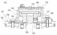
図6は、そのようなモータ110の断面構造であって、主にエンコーダ170が搭載されている領域に着目して示している。磁石ホルダ150は、磁石160が搭載される皿状の磁石搭載部151と、シャフト130の先端部分と嵌合する開口部153を有する突部152を有する。シャフト130の先端部分が開口部153に挿入され、側面からネジ155がシャフト130に突き当てられ、磁石ホルダ150がシャフト130に固定されている。モータ本体ケース120には、磁石ホルダ150を覆うように、エンコーダ170が取り付けられる。エンコーダ170には、磁石160に対向するようにセンサ基板172に取り付けられた磁気センサ175が備わる。
FIG. 6 is a cross-sectional structure of such a
ところで、上述したような、ホルダ側面からネジをシャフトに突き当てて磁石ホルダとシャフトとを固定する構造は、組付けが容易であったり、磁石と磁気センサとの距離の調整が可能であるという利点はあるものの、ネジを側面から入れるための十分な空間を確保する必要があり、高さ方向に厚くなってしまい、モータ全体の扁平化や小型化には不利であるという課題があった。 By the way, as described above, the structure in which the magnet holder and the shaft are fixed by abutting the screw against the shaft from the side of the holder is easy to assemble or the distance between the magnet and the magnetic sensor can be adjusted. Although there is an advantage, there is a problem that it is necessary to secure a sufficient space for inserting the screw from the side surface, and it becomes thick in the height direction, which is disadvantageous for flattening and miniaturization of the entire motor.
本発明は、上記の状況に鑑みなされたものであって、磁気式エンコーダ構造を有するモータにおいて、扁平化や小型化を容易にする技術を提供することにある。 The present invention has been made in view of the above situation, and it is an object of the present invention to provide a technique that facilitates flattening and miniaturization in a motor having a magnetic encoder structure.
本発明に係るモータは、NSの2極に着磁されている円盤状の磁石と、前記磁石の2極着磁分極線上であって前記磁石に対向して配置された磁気センサと、前記磁石を保持する磁石ホルダと、を有し、前記磁石ホルダは、前記磁石が配置される有底部と、前記有底部からモータ回転軸に設けられたネジ穴に嵌合するネジ付き突起部と、を備え、前記有底部は、前記磁石の着磁分極線に対して対称となる外形を呈している。 The motor according to the present invention includes a disc-shaped magnet that is magnetized on two NS poles, a magnetic sensor that is disposed on the two-pole magnetized polarization line of the magnet and faces the magnet, and the magnet A magnet holder that holds the magnet, and the magnet holder includes a bottomed portion on which the magnet is disposed, and a threaded protrusion that fits from the bottomed portion into a screw hole provided in the motor rotation shaft. The bottomed portion has an outer shape that is symmetric with respect to the magnetization polarization line of the magnet.
これによって、磁石ホルダを薄型化でき、その結果、モータの薄型化が実現できる。また、磁石ホルダを小さくすることにより、イナーシャ(慣性モーメント)を減らすことができる。これにより、特に低出力型のモータの場合は、回転部(回転軸、駆動用磁石など)に占める磁石ホルダのイナーシャを減らすことができるので応答性を高めることができる。また、従来の磁石ホルダを使用した場合と同等の回転部イナーシャとする場合では、磁石ホルダでのイナーシャを減らした分、駆動用磁石の体積を増やすことができるので、駆動力を高めることができる。 Thereby, the magnet holder can be thinned, and as a result, the motor can be thinned. Moreover, inertia (moment of inertia) can be reduced by making the magnet holder small. Thereby, especially in the case of a low output type motor, the inertia of the magnet holder occupying the rotating part (rotating shaft, driving magnet, etc.) can be reduced, so that the responsiveness can be improved. In addition, in the case of rotating part inertia equivalent to the case where a conventional magnet holder is used, the volume of the drive magnet can be increased by the amount of inertia in the magnet holder, so that the driving force can be increased. .
前記有底部は、円形の外周形状の一部が前記モータ回転軸を挟んで平行であって、前記磁石の着磁分極線に直交または平行にカットされたカット部を備えてもよい。 The bottomed portion may include a cut portion in which a part of a circular outer peripheral shape is parallel to the motor rotation shaft and cut perpendicularly or parallel to the magnetized polarization line of the magnet.
平行かつ対称にカットされたカット部により、磁石ホルダの締め込み等など、工程の作業性を向上させることができる。また、磁石の着磁分極線に対して、カット部の位置を決めることにより、磁石表面からの磁束について、製品ごとのばらつきを小さくできるので、磁気センサ出力のばらつきを小さくすることができる。また、カット部があることで、磁石着磁工程での着磁分極線の位置決めが容易にできる。 The workability of the process, such as tightening of the magnet holder, can be improved by the cut parts cut in parallel and symmetrically. Further, by determining the position of the cut portion with respect to the magnetized polarization line of the magnet, the variation from product to product can be reduced with respect to the magnetic flux from the magnet surface, so that the variation in magnetic sensor output can be reduced. In addition, the presence of the cut portion facilitates the positioning of the magnetization polarization line in the magnet magnetization process.
前記磁石ホルダは、前記有底部から磁石着磁面側に立ちあがる側面部を有し、前記側面部は、全周に着磁面より下がった段部と、全周に前記段部より立ち上がる最外周側面とを備えてもよい。 The magnet holder has a side portion that rises from the bottomed portion toward the magnet magnetized surface side, and the side surface portion has a stepped portion that descends from the magnetized surface on the entire circumference and an outermost periphery that rises from the stepped portion on the entire circumference. And a side surface.
全周の段部により隙間が形成され、磁石表面から外周への磁束漏れを少なくし、かつ全周に渡り同じ条件にすることができる。また、最外周側面により、例えば、磁石ホルダの外側にネジなどの磁性部材が配置されていた場合であっても、ネジなどの影響を受けない安定した磁束量を実現できる。 A gap is formed by the step portion on the entire circumference, magnetic flux leakage from the magnet surface to the outer periphery can be reduced, and the same condition can be obtained over the entire circumference. Moreover, even if it is a case where magnetic members, such as a screw, are arrange | positioned on the outer side of a magnet holder by the outermost peripheral side surface, the stable magnetic flux amount which is not influenced by a screw etc. is realizable.
前記磁石ホルダと前記モータ回転軸との嵌合位置に、嵌合高さを調整する嵌合調整部材を備えてもよい。 You may provide the fitting adjustment member which adjusts fitting height in the fitting position of the said magnet holder and the said motor rotating shaft.
嵌合調整部材により磁石着磁面の高さ調整できるので、磁石〜磁気センサ間の隙間を調整できる。 Since the height of the magnetized surface can be adjusted by the fitting adjusting member, the gap between the magnet and the magnetic sensor can be adjusted.
前記磁気センサを搭載する回路基板を支える回路基板ホルダを備え、前記回路基板ホルダの搭載面との境界領域に、前記搭載面の高さを調整する搭載面調整部材を備えてもよい。 A circuit board holder that supports the circuit board on which the magnetic sensor is mounted may be provided, and a mounting surface adjustment member that adjusts the height of the mounting surface may be provided in a boundary region with the mounting surface of the circuit board holder.
搭載面調整部材により磁石着磁面の高さ調整できるので、モータ回転軸と磁石ホルダとの固定後であっても、磁石〜磁気センサ間の隙間を調整できる。 Since the height of the magnetized surface can be adjusted by the mounting surface adjusting member, the gap between the magnet and the magnetic sensor can be adjusted even after the motor rotating shaft and the magnet holder are fixed.
本発明によれば、磁気式エンコーダ構造を有するモータにおいて、扁平化や小型化を容易にする技術を提供することができる。 ADVANTAGE OF THE INVENTION According to this invention, in the motor which has a magnetic encoder structure, the technique which makes flattening and size reduction easy can be provided.
以下、発明を実施するための形態(以下、「実施形態」という)を、図面を参照しつつ説明する。 Hereinafter, modes for carrying out the invention (hereinafter referred to as “embodiments”) will be described with reference to the drawings.
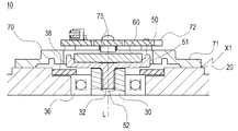
図1は、本実施形態に係るモータ10の断面構造を示す断面図である。このモータ10は、NSの2極に着磁されている磁石60に対向配置された磁気センサ75で回転磁界の変化を検出する磁気式のエンコーダ70を備える。本実施形態では、磁石60が配置される磁石ホルダ50とシャフト30との固定構造に特徴があるため、以下、主にその固定構造に着目して説明する。
FIG. 1 is a cross-sectional view showing a cross-sectional structure of a
モータ10の回転軸であるシャフト30は、モータ本体ケース20に取り付けられたベアリング36を介して、その一端を外部(図示では上方向)に露出させている。なお、ベアリング36は、押さえ部38によって固定されている。
One end of the
露出しているシャフト30の先端には、円盤状の磁石60を配置した磁石ホルダ50が取り付けられている。
A
モータ本体ケース20には、磁石ホルダ50を覆うようにエンコーダ70が取り付けられている。エンコーダ70は、モータ本体ケース20に固定されたエンコーダカバー71(回路基板ホルダ)と、その上端に設けられたセンサ基板72と、センサ基板72に取り付けられた磁気センサ75を備える。磁気センサ75は、回転軸線L上において、磁石60と対向する位置(磁石60の中心と対向する位置)に所定の間隔を有して配置されている。
An
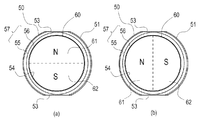
つづいて、磁石ホルダ50の構造及び磁石ホルダ50とシャフト30の固定について具体的に説明する。図2は磁石ホルダ50を示し、図2(a)が平面図、図2(b)が図2(a)のA−A断面図、図2(c)が図2(a)のB−B断面図である。また、図3は磁石60が搭載された磁石ホルダ50の平面図であって、図3(a)が平行部53と磁石60の着磁分極線が平行となるように配置された状態、図3(b)が直交するように配置された状態を示している。
Next, the structure of the
図2に示すように、磁石ホルダ50は、磁石60を配置する有底部51と、有底部51の底面から下方向に突出する円柱状のネジ付き突部52とを備える。ネジ付き突部52の外周には、所定ピッチのネジが形成されている。図2(b)及び(c)では、磁石60を破線で示している。
As shown in FIG. 2, the
有底部51は、平面視で略円形を呈しており、その円形の一部(側面部57の一部)が対向する位置、すなわち回転軸線Lを挟んで互いに平行になるようにカットされた一対の平行部53を有している。
The bottomed
また、有底部51は、磁石60が搭載される所定深さの磁石配置部54と、外周領域に於いて磁石着磁面側、すなわち図示で上方向に立ち上がる側面部57を備える。
The bottomed
側面部57は、全周に着磁面(搭載される磁石60の上面)より下がった所定幅t1の段部56と、段部56の全周外縁から上方に延出する最外周側面部55とを備える。最外周側面部55の上面位置は着磁面と略一致する。
The
すなわち、磁石60の外周部分と最外周側面部55との間に、所定幅t1の隙間が存在することになる。この隙間ができることで磁石60表面から外周への磁束漏れを少なくし、かつ全周に渡り同じ条件にすることができる。
That is, a gap having a predetermined width t1 exists between the outer peripheral portion of the
また、最外周側面部55により、例えば、磁石ホルダ50の外側近傍にネジなどの磁性部材が配置されていた場合であっても、ネジなどの影響を受けない安定した磁束量を実現できる。このような構造がないと、ネジがある回転角度位置で磁束が変化するなどするので、磁束量が安定しない場合もあり、特に近年では従来以上に精密なモータ制御が要求されることが多くなっており、その要求に応えることができる。
Further, the outermost peripheral
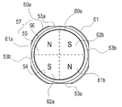
そして、図3に示す様に、上述の磁石ホルダ50の磁石配置部54に円盤状の磁石60がエポキシ樹脂等の接着剤で取り付けられ、NSの2極(N極部61、S極部62)に着磁される。このとき、図3(a)に示す様に、平行部53が磁石60の着磁分極線に平行となる状態、または、図3(b)に示す様に、平行部53が磁石60の着磁分極線に直交する状態に着磁される。
As shown in FIG. 3, a disc-shaped
磁石60の着磁分極線に対して、平行部53の位置を決めることにより、磁石60の表面からの磁束について、製品ごとのばらつきを小さくできる。すなわち、磁気センサ出力のばらつきを小さくすることができる。また、平行部53が存在することで、磁石着磁工程で平行部53を着磁ヘッドに対して位置決めできるので磁石ホルダ50に対する着磁分極線の位置決めが容易になる。
By determining the position of the
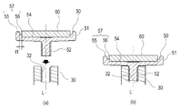
図4は磁石ホルダ50とシャフト30との固定工程を示す図であって、図4(a)が固定前の状態を示し、図4(b)が固定後の状態を示している。
4A and 4B are diagrams showing a fixing process between the
磁石ホルダ50を取り付ける側のシャフト30には、その上端に軸方向下側に向けて所定深さのネジ穴32が形成されている。このネジ穴32に、磁石ホルダ50のネジ付き突部52がねじ込まれ固定される。
A
上述の様に、磁石ホルダ50の有底部51には一対の平行部53が形成されており、平行部53により、磁石ホルダ50のシャフト30への締め込み等など、工程の作業性を向上させることができる。
As described above, the bottomed
なお、単純に磁石ホルダ50とシャフト30との固定を考えた場合、例えば、磁石配置部54の中心からボルト等でシャフト30に締め付けることも想定できる。しかし、磁石ホルダ50と磁石60とを固定し着磁した後に、磁石60と一体になった磁石ホルダ50をシャフト30に固定する必要があり、別途ボルトを用いる構成は、作業工程の関係から行うことができない。また、仮にボルト上に磁石60が配置されることになる場合は、磁石配置部54にボルトの頭を避ける為のスペースを作ることからそのスペース部分がヨークとして機能しない為、磁石60と磁気センサ75が対向位置することになる関係から、磁気センサ75の出力をばらつかせる原因になり現実的に採用することができない。
When simply fixing the
(本形態の主な効果)
以上、本実施形態によると、モータ10全体の扁平化や小型化を実現することができる。すなわち、従来であればネジを側面から入れるための十分な空間を確保する必要があり、高さ方向に厚くなってしまっていた。例えば、背景技術の図6(b)では、エンコーダ170の搭載面X2から磁気センサ175までの高さが厚くなっていた。しかし、図1に示す様に、本実施形態では、磁石ホルダ50を小さくすることで、エンコーダ70の搭載面X1から磁気センサ75までの高さを狭くすることができる。
(Main effects of this form)
As described above, according to the present embodiment, it is possible to realize flattening and downsizing of the
また、磁石ホルダ50を小さくすることにより、イナーシャ(慣性モーメント)を減らすことができる。これにより、特に低出力型のモータ10の場合は、回転部(回転軸、駆動用磁石など)に占める磁石ホルダ50のイナーシャを減らすことができるので応答性を高めることができる。また、従来の磁石ホルダを使用した場合と同等の回転部イナーシャとする場合では、磁石ホルダ50でのイナーシャを減らした分、駆動用磁石の体積を増やすことができるので、モータ10の駆動力を高めることができる。
Moreover, inertia (moment of inertia) can be reduced by making the
(他の実施の形態)
本発明を、実施の形態をもとに説明したが、この実施の形態は例示であり、それらの各構成要素の組み合わせ等にいろいろな変形例が可能なこと、またそうした変形例も本発明の範囲にあることは当業者に理解されるところである。
(Other embodiments)
Although the present invention has been described based on the embodiment, this embodiment is an exemplification, and various modifications can be made to combinations of the respective components, and such modifications are also included in the present invention. It will be understood by those skilled in the art that it is in the range.
図5は変形例に係る、磁石ホルダ50とシャフト30との固定工程を示す図であって、図5(a)が固定前の状態を示し、図5(b)が固定後の状態を示している。図示のように、シャフト30と磁石ホルダ50の間に、すなわち、シャフト30の上端に、嵌合高さを調整するためのワッシャ90(嵌合調整部材)が配置されてもよい。磁気センサ75と磁石60とのギャップ調整が容易になる。なお、ワッシャ90を複数用いてもよい。
FIGS. 5A and 5B are diagrams showing a fixing process of the
なお、ギャップ調整の観点から、図1において、エンコーダ70の搭載面X1に同様の調整部材(搭載面調整部材)が配置されて、エンコーダ70とモータ本体ケース20とが固定されてもよい。また、平行部53は一対に限る趣旨では無く複数対であってもよいが、安定した磁束の観点から、上下左右で対称であることが望ましい。また、上述の実施形態では、NS2極に着磁されている構成について説明したが、多極に着磁されている構成についても適用出来ることは当業者に理解されるところである。図7は、変形例に係る、
4極化された磁石60aが搭載された磁石ホルダ50aの平面図である。磁石60aは、2つのN極部61a、61bと2つのS極部62a、62bとに4極化されている。また、磁石ホルダ50aは上下左右対称となるように2対の平行部53a、53bを備える。上述のような平行部53が一対のみの構成で磁石60を多極化した場合、平行部53にかかる着磁領域と、平行部53にかからない着磁領域が必ずでてくる。そこで、図7のように、多極化した場合には、それに対応して複数対の平行部(ここでは2対の平行部53a、53b)を設け、磁束の流れを適正に調整し、磁束の強さのバラツキを低減することが望ましい。
From the viewpoint of gap adjustment, in FIG. 1, the same adjustment member (mounting surface adjustment member) may be disposed on the mounting surface X <b> 1 of the
It is a top view of the
10 モータ
20 モータ本体ケース
30 シャフト
32 ネジ穴
36 ベアリング
38 押さえ部
50、50a 磁石ホルダ
51 有底部
52 ネジ付き突部
53、53a、53b 平行部
54 磁石配置部
55 最外周側面部
56 段部
57 側面部
60、60a 磁石
61、61a、61b N極部
62、62a、62b S極部
70 エンコーダ
71 エンコーダカバー(回路基板ホルダ)
72 センサ基板
75 磁気センサ
90 ワッシャ(嵌合調整部材)
DESCRIPTION OF
72
Claims (5)
前記磁石の2極着磁分極線上であって前記磁石に対向して配置された磁気センサと、
前記磁石を保持する磁石ホルダと、
を有し、
前記磁石ホルダは、
前記磁石が配置される有底部と、
前記有底部からモータ回転軸に設けられたネジ穴に嵌合するネジ付き突起部と、
を備え、
前記有底部は、前記磁石の着磁分極線に対して対称となる外形を呈している
ことを特徴とするモータ。 A disc-shaped magnet magnetized on two NS poles;
A magnetic sensor disposed on the two-pole magnetized polarization line of the magnet and facing the magnet;
A magnet holder for holding the magnet;
Have
The magnet holder is
A bottomed portion on which the magnet is disposed;
A threaded protrusion that fits into a screw hole provided in the motor rotation shaft from the bottomed portion;
With
The motor according to claim 1, wherein the bottomed portion has an outer shape that is symmetric with respect to a magnetization polarization line of the magnet.
前記側面部は、全周に着磁面より下がった段部と、全周に前記段部より立ち上がる最外周側面とを備えることを特徴とする請求項1または2に記載のモータ。 The magnet holder has a side portion that rises from the bottomed portion to the magnet magnetized surface side,
3. The motor according to claim 1, wherein the side surface portion includes a stepped portion that is lowered from the magnetized surface on the entire periphery and an outermost peripheral side surface that rises from the stepped portion on the entire periphery.
Priority Applications (1)
| Application Number | Priority Date | Filing Date | Title |
|---|---|---|---|
| JP2016001707A JP6650760B2 (en) | 2016-01-07 | 2016-01-07 | motor |
Applications Claiming Priority (1)
| Application Number | Priority Date | Filing Date | Title |
|---|---|---|---|
| JP2016001707A JP6650760B2 (en) | 2016-01-07 | 2016-01-07 | motor |
Publications (2)
| Publication Number | Publication Date |
|---|---|
| JP2017123731A true JP2017123731A (en) | 2017-07-13 |
| JP6650760B2 JP6650760B2 (en) | 2020-02-19 |
Family
ID=59306458
Family Applications (1)
| Application Number | Title | Priority Date | Filing Date |
|---|---|---|---|
| JP2016001707A Active JP6650760B2 (en) | 2016-01-07 | 2016-01-07 | motor |
Country Status (1)
| Country | Link |
|---|---|
| JP (1) | JP6650760B2 (en) |
Cited By (7)
| Publication number | Priority date | Publication date | Assignee | Title |
|---|---|---|---|---|
| WO2019225425A1 (en) * | 2018-05-21 | 2019-11-28 | Ntn株式会社 | Electric oil pump |
| JP2020162399A (en) * | 2019-03-28 | 2020-10-01 | キヤノンプレシジョン株式会社 | Brushless motor |
| WO2021104950A1 (en) * | 2019-11-30 | 2021-06-03 | Beijing Siling Robot Technology Co., Ltd. | Modular robot joint, encoder reading head position adjustment mechanism and method for adjusting the position of an encoder reading head |
| JP2022053616A (en) * | 2020-09-25 | 2022-04-06 | 日本電産サンキョー株式会社 | Encoder and motor |
| WO2023042808A1 (en) * | 2021-09-14 | 2023-03-23 | Ckd株式会社 | Rotary encoder |
| WO2024024151A1 (en) | 2022-07-27 | 2024-02-01 | アルプスアルパイン株式会社 | Magnetic field detection device |
| TWI915592B (en) | 2021-09-14 | 2026-02-21 | 日商喜開理股份有限公司 | Rotary encoder |
Citations (4)
| Publication number | Priority date | Publication date | Assignee | Title |
|---|---|---|---|---|
| JP2011160636A (en) * | 2010-02-04 | 2011-08-18 | Denso Corp | Motor, and power steering device employing the same |
| JP2013009573A (en) * | 2011-06-27 | 2013-01-10 | Nidec Sankyo Corp | Motor |
| JP2014183674A (en) * | 2013-03-21 | 2014-09-29 | Hitachi Automotive Systems Steering Ltd | Rotation angle detection apparatus |
| WO2014163293A1 (en) * | 2013-04-01 | 2014-10-09 | New Motech Co., Ltd. | Motor with simple assembling sensor magnet |
-
2016
- 2016-01-07 JP JP2016001707A patent/JP6650760B2/en active Active
Patent Citations (4)
| Publication number | Priority date | Publication date | Assignee | Title |
|---|---|---|---|---|
| JP2011160636A (en) * | 2010-02-04 | 2011-08-18 | Denso Corp | Motor, and power steering device employing the same |
| JP2013009573A (en) * | 2011-06-27 | 2013-01-10 | Nidec Sankyo Corp | Motor |
| JP2014183674A (en) * | 2013-03-21 | 2014-09-29 | Hitachi Automotive Systems Steering Ltd | Rotation angle detection apparatus |
| WO2014163293A1 (en) * | 2013-04-01 | 2014-10-09 | New Motech Co., Ltd. | Motor with simple assembling sensor magnet |
Cited By (11)
| Publication number | Priority date | Publication date | Assignee | Title |
|---|---|---|---|---|
| WO2019225425A1 (en) * | 2018-05-21 | 2019-11-28 | Ntn株式会社 | Electric oil pump |
| JP2020162399A (en) * | 2019-03-28 | 2020-10-01 | キヤノンプレシジョン株式会社 | Brushless motor |
| WO2021104950A1 (en) * | 2019-11-30 | 2021-06-03 | Beijing Siling Robot Technology Co., Ltd. | Modular robot joint, encoder reading head position adjustment mechanism and method for adjusting the position of an encoder reading head |
| US12337466B2 (en) | 2019-11-30 | 2025-06-24 | Agile Robots Se | Modular robot joint, encoder reading head position adjustment mechanism and method for adjusting the position of an encoder reading head |
| JP2022053616A (en) * | 2020-09-25 | 2022-04-06 | 日本電産サンキョー株式会社 | Encoder and motor |
| JP7517927B2 (en) | 2020-09-25 | 2024-07-17 | ニデックインスツルメンツ株式会社 | Encoders and Motors |
| WO2023042808A1 (en) * | 2021-09-14 | 2023-03-23 | Ckd株式会社 | Rotary encoder |
| JP2023042449A (en) * | 2021-09-14 | 2023-03-27 | Ckd株式会社 | Rotary encoder |
| JP7681479B2 (en) | 2021-09-14 | 2025-05-22 | Ckd株式会社 | Rotary Encoder |
| TWI915592B (en) | 2021-09-14 | 2026-02-21 | 日商喜開理股份有限公司 | Rotary encoder |
| WO2024024151A1 (en) | 2022-07-27 | 2024-02-01 | アルプスアルパイン株式会社 | Magnetic field detection device |
Also Published As
| Publication number | Publication date |
|---|---|
| JP6650760B2 (en) | 2020-02-19 |
Similar Documents
| Publication | Publication Date | Title |
|---|---|---|
| JP6650760B2 (en) | motor | |
| US8823232B2 (en) | Rotary electric machine | |
| US10047754B2 (en) | Brushless motor and fan using the motor | |
| EP2677643B1 (en) | Rotary solenoid | |
| JP2014225998A (en) | Driving device | |
| US7224092B2 (en) | Brushless motor | |
| JP2828171B2 (en) | Encapsulated step motor | |
| US20200251964A1 (en) | Motor and air blowing device | |
| JP2018117429A (en) | Brushless motor | |
| US20070001532A1 (en) | Brushless DC motor and magnetic compensation method thereof | |
| KR100739207B1 (en) | Vibrator motor for Brushless Direct Current | |
| JP2009100540A (en) | Motor equipped with chucking device and disk drive unit mounted with the motor | |
| JP2001069738A (en) | External circumference opposing type motor | |
| JP2009261062A (en) | Brushless motor | |
| JP2016086557A (en) | Motor, and structure for fixing driven member to rotary shaft | |
| US20160198266A1 (en) | Earphone and manufacturing method for earphone | |
| KR20090056330A (en) | BLC vibration motor | |
| JP2019068524A (en) | motor | |
| JP5290608B2 (en) | Axial gap motor | |
| JP2020162399A (en) | Brushless motor | |
| JP2009268196A (en) | Brushless motor | |
| JP6659169B2 (en) | Rotor and rotating electric machine | |
| JP5953545B2 (en) | Rotary solenoid | |
| JP2010004599A (en) | Flat vibration motor | |
| JP7131032B2 (en) | motor and blower |
Legal Events
| Date | Code | Title | Description |
|---|---|---|---|
| A621 | Written request for application examination |
Free format text: JAPANESE INTERMEDIATE CODE: A621 Effective date: 20181207 |
|
| A977 | Report on retrieval |
Free format text: JAPANESE INTERMEDIATE CODE: A971007 Effective date: 20190919 |
|
| A131 | Notification of reasons for refusal |
Free format text: JAPANESE INTERMEDIATE CODE: A131 Effective date: 20191001 |
|
| A521 | Request for written amendment filed |
Free format text: JAPANESE INTERMEDIATE CODE: A523 Effective date: 20191023 |
|
| TRDD | Decision of grant or rejection written | ||
| A01 | Written decision to grant a patent or to grant a registration (utility model) |
Free format text: JAPANESE INTERMEDIATE CODE: A01 Effective date: 20200107 |
|
| A61 | First payment of annual fees (during grant procedure) |
Free format text: JAPANESE INTERMEDIATE CODE: A61 Effective date: 20200121 |
|
| R150 | Certificate of patent or registration of utility model |
Ref document number: 6650760 Country of ref document: JP Free format text: JAPANESE INTERMEDIATE CODE: R150 |