JP2017123727A - Method for manufacturing electric motor and bus ring for the same - Google Patents
Method for manufacturing electric motor and bus ring for the same Download PDFInfo
- Publication number
- JP2017123727A JP2017123727A JP2016001524A JP2016001524A JP2017123727A JP 2017123727 A JP2017123727 A JP 2017123727A JP 2016001524 A JP2016001524 A JP 2016001524A JP 2016001524 A JP2016001524 A JP 2016001524A JP 2017123727 A JP2017123727 A JP 2017123727A
- Authority
- JP
- Japan
- Prior art keywords
- winding
- connection portion
- bus ring
- winding connection
- electric motor
- Prior art date
- Legal status (The legal status is an assumption and is not a legal conclusion. Google has not performed a legal analysis and makes no representation as to the accuracy of the status listed.)
- Granted
Links
Images
Landscapes
- Insulation, Fastening Of Motor, Generator Windings (AREA)
- Manufacture Of Motors, Generators (AREA)
- Windings For Motors And Generators (AREA)
Abstract
Description
本発明は、複数の磁性体コアに巻線を巻き回してなるステータと、ステータに対して回転するロータと、巻線が接続されるバスリングとを備えた電動機の製造方法、及び電動機用バスリングに関する。 The present invention relates to a method for manufacturing an electric motor including a stator formed by winding a winding around a plurality of magnetic cores, a rotor rotating with respect to the stator, and a bus ring to which the winding is connected, and an electric motor bus. Regarding the ring.
従来、例えば電気自動車や所謂ハイブリッド車等に搭載され、車両の駆動力を発生する電動機として、バスリングを介して巻線に駆動電流が供給されるものが知られている(例えば、特許文献1参照)。 2. Description of the Related Art Conventionally, as an electric motor that is mounted on, for example, an electric vehicle or a so-called hybrid vehicle and generates a driving force of the vehicle, a motor that supplies a driving current to a winding via a bus ring is known (for example, Patent Document 1). reference).
特許文献1に記載の電動機は、環状に配置された複数の磁極を有する磁性体コアと、複数の素線を束ねて形成された巻線を磁性体コアの複数の磁極ごとに巻き回してなるステータと、ステータに対して回転するロータと、ステータと同心状に配置され、巻線の端部が接続される複数の環状のバスリングとを備えている。 The electric motor described in Patent Document 1 is formed by winding a magnetic core having a plurality of magnetic poles arranged in an annular shape and a winding formed by bundling a plurality of strands around the plurality of magnetic poles of the magnetic core. A stator, a rotor that rotates with respect to the stator, and a plurality of annular bus rings that are arranged concentrically with the stator and to which ends of the windings are connected.
上記のバスリングは、断面円形の導体の表面を絶縁体で被覆し、絶縁体から露出させた複数の導体の部分に巻線の端部が接続される巻線接続部を形成している。巻線接続部は、一箇所に所定の開口を有する環状に形成されている。バスリングの巻線接続部に巻線の端部を接続する際は、巻線接続部に巻線の端部を挿通し、巻線接続部と巻線の端部とが接触するように巻線接続部を加圧し、巻線接続部を加圧した状態で巻線接続部に通電して巻線接続部と巻線の端部とを溶着させる。巻線接続部の加圧時には、開口の開口幅が巻線の素線の太さよりも狭くなるように巻線接続部を周方向に押圧する。 In the above-described bus ring, the surface of a conductor having a circular cross section is covered with an insulator, and a winding connection portion is formed in which ends of the winding are connected to a plurality of conductor portions exposed from the insulator. The winding connection part is formed in an annular shape having a predetermined opening at one place. When connecting the winding end to the winding connection of the bus ring, insert the winding end into the winding connection so that the winding connection and the end of the winding are in contact. The wire connection portion is pressurized, and the winding connection portion is energized while the winding connection portion is pressurized to weld the winding connection portion and the end of the winding. When pressurizing the winding connection portion, the winding connection portion is pressed in the circumferential direction so that the opening width of the opening is narrower than the thickness of the wire of the winding.
特許文献1に記載の電動機では、巻線接続部と巻線の端部とを接続する際、巻線接続部は断面円形であるため、巻線接続部を加圧するときに巻線の端部と巻線接続部とが線接触となり、接続部の接触面積が十分でないことから、接続不良の原因となる可能性があった。この場合には、接続作業のやり直しが必要となり、作業効率向上の妨げとなっていた。 In the electric motor described in Patent Document 1, when connecting the winding connection portion and the end portion of the winding, the winding connection portion is circular in cross section. The winding connection portion is in line contact, and the contact area of the connection portion is not sufficient, which may cause connection failure. In this case, it is necessary to redo the connection work, which hinders improvement in work efficiency.
そこで、本発明は、巻線の端部との接続を確実に行うことができ、もって作業効率の向上を図ることが可能な電動機の製造方法及び電動機用バスリングを提供することを目的とする。 Accordingly, an object of the present invention is to provide a method of manufacturing an electric motor and a bus ring for the electric motor that can reliably connect the end of the winding and can improve the working efficiency. .
本発明は、上記課題を解決することを目的として、環状に配置された複数の磁極を有する磁性体コアに、複数の素線を束ねて形成された巻線を前記複数の磁極ごとに巻き回してなるステータと、前記ステータに対して回転するロータと、前記ステータと同心状に配置され、前記巻線の端部が接続される複数の環状のバスリングとを備えた電動機の製造方法であって、前記バスリングの素材となる断面円形状の導体線を塑性変形させ、前記巻線の端部を挟んで向かい合う前記巻線との接触面が平坦面に加工された巻線接続部を形成するバスリング形成工程と、前記バスリングの前記巻線接続部に前記巻線の端部を挿通させる挿通工程と、前記巻線接続部を前記バスリングの周方向に押圧して前記平坦面と前記巻線の端部とが接触するように前記巻線接続部を変形させる変形工程と、前記巻線接続部が変形された状態で前記巻線接続部に通電し、前記巻線接続部と前記巻線の端部とを溶着する溶着工程とを有する、電動機の製造方法を提供する。 In order to solve the above-mentioned problems, the present invention winds a winding formed by bundling a plurality of strands around a plurality of magnetic poles around a magnetic core having a plurality of magnetic poles arranged in an annular shape. And a plurality of annular bus rings arranged concentrically with the stator and connected to the ends of the windings. Then, the conductor wire having a circular cross section as a material for the bus ring is plastically deformed to form a winding connection portion in which a contact surface facing the winding across the end of the winding is processed into a flat surface. A bus ring forming step, an insertion step of inserting an end portion of the winding into the winding connection portion of the bus ring, and pressing the winding connection portion in a circumferential direction of the bus ring and the flat surface So that the end of the winding contacts A deformation step of deforming the wire connection portion, and a welding step of energizing the winding connection portion in a state where the winding connection portion is deformed and welding the winding connection portion and the end of the winding. A method for manufacturing an electric motor is provided.
また、本発明は、上記課題を解決することを目的として、複数の素線を束ねて形成された巻線が接続される複数の巻線接続部、及び前記複数の巻線接続部の間の複数の円弧部を有し、前記巻線を磁性体コアに巻き回してなる電動機のステ―タと同心状に配置される電動機用バスリングであって、前記複数の円弧部は、少なくとも一部が絶縁体で被覆された断面円形状の芯線を円弧状に湾曲してなり、前記複数の巻線接続部は、前記巻線の端部を挟んで向かい合う前記巻線との接触面が平坦面に加工されている、電動機用バスリングを提供する。 In addition, for the purpose of solving the above-described problems, the present invention provides a plurality of winding connection portions to which windings formed by bundling a plurality of strands are connected, and between the plurality of winding connection portions. An electric motor bus ring having a plurality of arc portions and arranged concentrically with a motor stator formed by winding the winding around a magnetic core, wherein the arc portions are at least partially The core wire having a circular cross section covered with an insulator is curved in an arc shape, and the plurality of winding connection portions have flat contact surfaces with the windings facing each other across the end portions of the windings. An electric motor bus ring is provided.
本発明に係る電動機の製造方法及び電動機用バスリングによれば、巻線の端部との接続を確実に行うことができ、もって作業効率の向上を図ることが可能である。 According to the method for manufacturing an electric motor and the bus ring for an electric motor according to the present invention, the connection with the end of the winding can be reliably performed, and thus the working efficiency can be improved.
[実施の形態]
本発明の実施の形態に係る電動機について、図1乃至図6を参照して説明する。
[Embodiment]
An electric motor according to an embodiment of the present invention will be described with reference to FIGS.
(電動機1の構成)
まず、電動機1の構成について、図1を参照して説明する。
(Configuration of electric motor 1)
First, the configuration of the electric motor 1 will be described with reference to FIG.
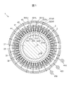
図1は、本実施の形態に係る電動機1の構成例の概略について説明する模式図である。 FIG. 1 is a schematic diagram for explaining an outline of a configuration example of an electric motor 1 according to the present embodiment.
この電動機1は、固定子であるステータ3と、ステータ3に対して回転するロータ2と、複数の素線(後述する図6参照)320が撚られて束になって形成された巻線32が接続される第1乃至第4のバスリング41〜44とを備えている。巻線32を構成する素線は、銅線がエナメルで被覆されたエナメル線を用いることが可能である。
The electric motor 1 includes a
ロータ2は、図略の軸受によってステータ3と同軸上で回転可能に支持されたシャフト21と、シャフト21の外周面に固定されてN極及びS極が周方向に交互に着磁された円筒状の磁石22とを有している。
The rotor 2 includes a
ステータ3は、シャフト21の回転軸Oを中心として環状に配置された複数(本実施の形態では24個)の磁性体コア31に巻線32を巻き回して構成される。本実施の形態では、24個の磁性体コア31が、8個のU相の磁性体コア31U、8個のV相の磁性体コア31V、及び8個のW相の磁性体コア31から構成され、ロータ2の回転方向Rに沿って、U相の磁性体コア31U、V相の磁性体コア31V、W相の磁性体コア31Wの順に並んで配置されている。複数の磁性体コア31は、本発明の「複数の磁極を有する磁性体コア」の一態様である。複数の磁性体コア31は、複数の磁極を有する一体物の磁性体コアでもよい。
The
U相の磁性体コア31Uには、巻線32としてU相の巻線32Uが巻き回されている。このU相の巻線32Uは、その両端部のうち一方の端部321Uが第1のバスリング41に電気的に接続され、他方の端部322Uが第4のバスリング44に電気的に接続されている。
A U-phase winding 32U is wound as a winding 32 around the U-phase magnetic core 31U. The U-phase winding 32 </ b> U has one
V相の磁性体コア31Vには、巻線32としてV相の巻線32Vが巻き回されている。このV相の巻線32Vは、その両端部のうち一方の端部321Vが第2のバスリング42に電気的に接続され、他方の端部322Vが第4のバスリング44に電気的に接続されている。
A V-phase winding 32V is wound as a winding 32 around the V-phase
W相の磁性体コア31Wには、巻線32としてW相の巻線32Wが巻き回されている。このW相の巻線32Wは、その両端部のうち一方の端部321Wが第3のバスリング43に電気的に接続され、他方の端部322Wが第4のバスリング44に電気的に接続されている。
A W-phase winding 32 </ b> W is wound around the W-phase
したがって、第4のバスリング44は、U相の巻線32Uの他方の端部322U、V相の巻線32Vの他方の端部322V、及びW相の束32Wの他方の端部322Wが電気的に接続された中性相のバスリングとして機能している。
Therefore, the
U相の巻線32Uの一方の端部321Uは、ステータ3の周方向におけるV相の巻線32V側に位置し、他方の端部322Uは、ステータ3の周方向におけるW相の巻線32W側に位置している。V相の巻線32Vの一方の端部321Vは、ステータ3の周方向におけるW相の巻線32W側に位置し、他方の端部322Vは、ステータ3の周方向におけるU相の巻線32U側に位置している。W相の巻線32Wの一方の端部321Wは、ステータ3の周方向におけるU相の巻線32U側に位置し、他方の端部322Wは、ステータ3の周方向におけるV相の巻線32V側に位置している。
One
第1乃至第3のバスリング41〜43には、それぞれ給電端子410,420,430が接続され、この給電端子410,420,430を介して図略のインバータから120°ずつ位相がずれた正弦波状の駆動電流が第1乃至第3のバスリング41〜43に供給される。この駆動電流によってステータ3に回転磁界が形成され、磁石22がこの回転磁界による吸引力及び反発力により回転力を受けてシャフト21を回転軸Oを中心として回転させる。
The first to third bus rings 41 to 43 are connected to
(ステータ3の構成)
次に、ステータ3の構成について、図2及び図3を参照して説明する。
(Configuration of stator 3)
Next, the structure of the
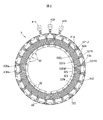
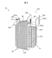
図2は、第1乃至第3のバスリング41〜43が組み付けられたステータ3をシャフト21の回転軸O方向から見た平面図である。図3は、磁性体コア組立体30の構成例を示す斜視図である。
FIG. 2 is a plan view of the
ステータ3は、図2に示すように、磁性体コア31に巻線32を巻き回してなる複数(本実施の形態では24個)の磁性体コア組立体30が環状に配置されることにより構成されている。より具体的には、磁性体コア組立体30は、図3に示すように、複数の電磁鋼板310を積層してなる磁性体コア31に絶縁性のインシュレータ33を装着し、インシュレータ33を介して磁性体コア31の外側に巻線32を巻き回してなる。
As shown in FIG. 2, the
インシュレータ33は、磁性体コア31と巻線32との間に介在する絶縁部336(図3において破線で示す)と、絶縁部336をロータ2(図1参照)の径方向に挟んで対向する第1の壁部331及び第2の壁部332と、第1の壁部331からシャフト21の回転軸O(図1参照)側に向かって張り出した内鍔部334と、第2の壁部332から第1の壁部331とは反対側に向かって張り出した外鍔部335と、外鍔部335の端部から第2の壁部332に対向するように立設された第3の壁部333とを一体に有している。
The
第1乃至第3の壁部331〜333は、シャフト21の回転軸O側からロータ2の径方向に沿って第1の壁部331、第2の壁部332、第3の壁部333の順に立設されている。
The first to
第2の壁部332には、巻線32の一方の端部321を挿通させる第2の挿通部332aが形成され、巻線32の一方の端部321は、挿通部332aからシャフト21の回転軸O方向に平行な方向に沿って引き出されている。第1の壁部331には、巻線32の他方の端部322を挿通させる第1の挿通部331aが形成され、巻線32の他方の端部322は、第1の挿通部331aからシャフト21の回転軸O側に向かって引き出されている。
The
また、インシュレータ33は、第1乃至第3のバスリング41〜43を保持する保持部330を有している。保持部330は、図3に示すように、第2の壁部332の一部、第3の壁部333、及び第2の壁部332の一部と第3の壁部333との間を連結する外鍔部335によって構成されている。外鍔部335は、保持部330の底部として機能する。本実施の形態では、保持部330は、巻線32(U相の巻線32U,V相の巻線32V,W相の巻線32W)の外周側に設けられている。第3の壁部333には、第1乃至第3のバスリング41〜43を固定する固定部材40が嵌合される嵌合凹部333aが形成されている。
The
(第1乃至第3のバスリング41〜43の構成)
次に、第1乃至第3のバスリング41〜43の構成について、図2及び図4を参照して説明する。
(Configuration of the first to third bus rings 41 to 43)
Next, the configuration of the first to third bus rings 41 to 43 will be described with reference to FIGS.
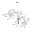
図4は、第1乃至第3のバスリング41〜43を示し、端子部41a,42a,43a及びその周辺部の拡大斜視図である。
FIG. 4 shows the first to third bus rings 41 to 43, and is an enlarged perspective view of the
図2に示すように、第1乃至第3のバスリング41〜43は、シャフト21の回転軸O(図1参照)方向に沿って並んで配置され、複数(本実施の形態では24個)の固定部材40によって一括して固定された状態でステータ3の保持部330に保持されている。
As shown in FIG. 2, the first to third bus rings 41 to 43 are arranged side by side along the direction of the rotation axis O (see FIG. 1) of the
第1乃至第3のバスリング41〜43は、例えば銅等の良電導性の金属からなる断面円形状の中心導体400aを樹脂からなる絶縁体400bで被覆した線状の絶縁電線400を屈曲して形成されている。中心導体400aは、本発明の「導体線」の一態様である。
The first to third bus rings 41 to 43 are formed by bending a linear
第1のバスリング41は、ステータ3の径方向内側に突出し、U相の巻線32Uの一方の端部321Uが接続される複数(本実施の形態では8個)の端子部41aと、ステータ3の周方向に沿って並ぶ複数(本実施の形態では8個)の円弧部412とを有している。複数の端子部41aは、複数の円弧部412の間に設けられている。また、第1のバスリング41の両端部では、絶縁体400bから中心導体400aが露出し、この露出した中心導体400aに給電端子410が圧着又は加締めにより接続されている。
The
第1のバスリング41は、中心導体400aを塑性変形させ、巻線32の端部を挟んで向かい合う巻線32との接触面が平坦面411dに加工された複数の巻線接続部42aを有している。円弧部412は、少なくとも一部が絶縁体400bで被覆された断面円形状の芯線を円弧状に湾曲して形成されている。本実施の形態では、端子部41aの近傍を除く円弧部412の一部が絶縁体400bで被覆されているが、円弧部412の全体が縁体400bで被覆されていてもよい。
The
第1のバスリング41と同様にして、第2のバスリング42は、V相の巻線32Vの一方の端部321Vが接続される複数(本実施の形態では8個)の端子部42aと、複数(本実施の形態では8個)の円弧部422とを有している。また、第2のバスリング42の両端部には、給電端子420が接続されている。
Similarly to the
第1及び第2のバスリング41,42と同様にして、第3のバスリング43は、W相の巻線32Wの一方の端部321Wが接続される複数(本実施の形態では8個)の端子部43aと、複数(本実施の形態では8個)の円弧部432とを有している。また、第3のバスリング43の両端部には、給電端子430が接続されている。
Similarly to the first and second bus rings 41 and 42, the
第1乃至第3のバスリング41〜43は、シャフト21の回転軸O方向に沿って並べて配置したときに、第1のバスリング41の端子部41aがU相の巻線32Uの一方の端部321Uの引き出し位置に、第2のバスリング42の端子部42aがV相の巻線32Vの一方の端部321Vの引き出し位置に、第3のバスリング43の端子部43aがW相の巻線32Wの一方の端部321Wの引き出し位置に、それぞれ対応するようにステータ3の周方向に沿って等間隔に配置されている。
When the first to third bus rings 41 to 43 are arranged side by side along the direction of the rotation axis O of the
U相の巻線32U、V相の巻線32V、及びW相の巻線32Wの一方の端部321U,321V,321Wは、ステータ3側からシャフト21の回転軸Oに平行な方向に沿って第1乃至第3のバスリング41〜43の端子部41a,42a,43aにそれぞれ挿通されている。なお、図4では、一方の端部321U,321V,321WのうちV相の巻線32Vの一方の端部321Vが端子部42aに挿通されている様子を示す。
One
(バスリングの巻線接続部の形成方法)
次に、1乃至第3のバスリング41〜43における端子部41a,42a,43aの巻線接続部411,421,431の形成方法について、図5を参照して説明する。
(Method of forming winding connection part of bus ring)
Next, a method of forming the winding
なお、第1乃至第3のバスリング41〜43における端子部41a,42a,43aの巻線接続部411,421,431の構造は全て同一であるため、第1のバスリング41における端子部41aの巻線接続部411の形成方法を例にとって、以下説明する。
In addition, since all the structure of the coil | winding connection part 411,421,431 of the
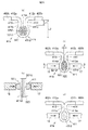
図5(a)〜(c)は、第1のバスリング41の形成工程(バスリング形成工程)を示す説明図である。図5(a)は、巻線接続部411の形成工程(巻線接続部形成工程)を示す断面図、図5(b)は、図5(a)のA−A線断面図、図5(c)は、巻線接続部411及び一対の延在部413,414を含む端子部41aの形成工程(端子部形成工程)を示す正面図である。
FIGS. 5A to 5C are explanatory views showing a process of forming the first bus ring 41 (bus ring forming process). 5A is a cross-sectional view showing a step of forming the winding connection portion 411 (winding connection portion forming step), FIG. 5B is a cross-sectional view taken along line AA of FIG. (C) is a front view showing a forming step (terminal portion forming step) of the
このバスリング形成工程では、バスリングの素材となる断面円形状の導体線を塑性変形させ、巻線32の端部321を挟んで向かい合う巻線32との接触面が平坦面411dに加工された巻線接続部411を形成し、その後に、巻線絶縁部411を一箇所に開口411aを有する環状に形成する。
In this bus ring forming step, a conductor wire having a circular cross section as a material of the bus ring is plastically deformed, and a contact surface with the winding 32 facing the
まず、芯線としての中心導体400aを絶縁体400bで被覆した絶縁電線400を用意する。次に、絶縁電線400のうち巻線接続部411となる部分及びその周辺部の絶縁体400bを除去する。この絶縁体400bを除去する工程は、例えばカッタ等の刃具を用いて除去する範囲の絶縁体400bの両端部に周方向の切れ込みを入れると共に、その両端部間における絶縁体400bに絶縁電線400の長手方向に沿う切れ込みを入れ、その後に絶縁体400bを取り除くことにより行うことができる。絶縁電線400から絶縁体400bを除去すると、中心導体400aが露出する。
First, an
次に、図5(a)に示すように、絶縁体400bから露出している中心導体400aのうち第1のバスリング41の巻線接続部411となる領域を受けダイス11と押しダイス12で挟むよう配置し、押しダイス12を受けダイス11に向けて加圧して巻線接続部411を形成する(巻線接続部形成工程)。
Next, as shown in FIG. 5 (a), a region that becomes the winding
受けダイス11は、所定の間隔を設けて形成された直線状の一対の第1の受け面11a,11aと、互いに逆方向に傾斜した直線状の一対の第3の受け面11c,11cと、第1の受け面11aと第3の受け面11cとを接続する弧状の一対の第2の受け面11b,11bと、一対の第3の受け面11c,11cを接続する弧状の第4の受け面11dとを有する。第1乃至第4の受け面11a〜11dは、図5(a)の紙面に垂直な断面において中心導体400aの外径に対応させて弧状に形成されている。
The receiving die 11 includes a pair of linear
押しダイス12は、先端側に弧状の先端面12aを有する。この先端面12aは、図5(b)に示す断面において平坦に形成されている。
The push die 12 has an
受けダイス11に対して押しダイス12を加圧すると、図5(b)に示すように、中心導体400aは、受けダイス11の第4の受け面11dによって弧状が保たれ、押しダイス12の先端面12aによって巻線34に面する面にロータ2の回転軸と略平行な平坦面411dが形成され(後述する図6(c)参照)、かつ内側に平坦面411dを有する巻線接続部411が形成される。すなわち、本実施の形態では、巻線接続部411の形成工程において、中心導体400aの曲げと平坦面411dの形成とが同時に行われる。ただし、中心導体400aの曲げ工程と、平坦面411dの形成工程とを、別々の工程で行ってもよい。この場合、加工の容易性を考慮すると、中心導体400aの一部を塑性変形させて平坦面411dを形成した後に、中心導体400aをV字状乃至U字状に曲げ加工することが望ましい。
When the
次に、図5(c)に示すように、受けダイス13を巻線接続部411の中心に対応させて配置し、中心導体400aを一対の押しダイス14で斜めの方向に加圧する。
Next, as shown in FIG. 5C, the receiving die 13 is disposed so as to correspond to the center of the winding
受けダイス13は、後述する図6(a)に示す巻線接続部411の開口411aに対応した幅を有する凸部13aを備えている。押しダイス14,15は、先端側に互いに直交する直交面14a,15aを有する。
The receiving die 13 includes a
受けダイス13に対して一対の押しダイス14を加圧すると、隣り合う一対の円弧部412a,412bと開口部411aを挟む巻線接続部411の両端部411b,411cとの間に介在する一対の延在部413,414が形成される。すなわち、巻線接続部411は、一箇所に開口411aを有する環状に形成される。
When a pair of pressing dies 14 are pressed against the receiving
以上のようにして第1のバスリング41に巻線接続部411、及び一対の延在部413,414を有する端子部41aが形成される。その後、第1のバスリング41は、図2に示すように、曲げ加工により環状に形成される。
As described above, the
(巻線接続部と巻線の端部との接続方法)
次に、第1乃至第3のバスリング41〜43における端子部41a,42a,43aの巻線接続部411,421,431とU相の巻線32U,V相の巻線32V,W相の巻線32Wの一方の端部321U,321V,321Wとの接続方法について、図6(a)〜(d)を参照して説明する。
(Connection method between winding connection and winding end)
Next, the winding
なお、第1乃至第3のバスリング41〜43における端子部41a,42a,43aの巻線接続部411,421,431とU相の巻線32U,V相の巻線32V,W相の巻線32Wの一方の端部321U,321V,321Wとの接続方法は全て同一であるため、第1のバスリング41における端子部41aの巻線接続部411とU相の巻線32Uの一方の端部321Uとの接続方法を例にとって、以下説明する。
It should be noted that the
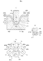
図6(a)〜(d)は、第1のバスリング41の巻線接続部411とU相の巻線32Uの一方の端部321Uとの接続過程を示す説明図であり、図6(a)は、U相の巻線42Uの一方の端部321Uが巻線接続部411に挿通された状態、図6(b)は、巻線接続部411が加圧されている状態、図6(c)は、図6(b)のB−B線断面図、図6(d)は、巻線接続部411とU相の巻線32Uの一方の端部321Uとが溶着している状態を示す。なお、図6(d)では、U相の巻線32Uの一方の端部321Uを破線で示している。
FIGS. 6A to 6D are explanatory views showing a connection process between the winding
図6(a)に示すように、端子部41aは、一箇所に開口411aを有する環状に形成された巻線接続部411と、隣り合う一対の円弧部412a,412bと開口411aを挟む巻線接続部411の両端部411b,411cとの間に介在する一対の延在部413,414とを有している。
As shown in FIG. 6A, the
本実施の形態では、一対の延在部413,414は、隣り合う一対の円弧部412a,412bのそれぞれの端部からステータ3(図2参照)の径方向内側に向かって平行に延在している。図6(a)に示すように、一対の延在部413,414の延在方向の長さL1は、例えば円弧部412a,412bから巻線接続部411における第1のバスリング41の径方向の先端までの距離L2の30〜60%である。
In the present embodiment, the pair of extending
端子部41aの巻線接続部411とU相の巻線32Uの一方の端部321Uとの接続方法は、巻線接続部411にU相の巻線32Uの一方の端部321Uを挿通させる挿通工程(図6(a)参照)と、巻線接続部411を第1のバスリング41の周方向に押圧して巻線接続部411とU相の巻線32Uの一方の端部321Uとが接触するように巻線接続部411を変形させる変形工程(図6(b)参照)と、巻線接続部411に通電して巻線接続部411とU相の巻線32Uの一方の端部321Uとを溶着する溶着工程(図6(d)参照)とを有する。
The connection method between the winding
図6(b)に示すように、変形工程では、巻線接続部411の開口411aの開口幅dがU相の巻線32Uの素線320の太さよりも狭くなるように、一対の電極16,17で巻線接続部411を挟んで図6(b)の矢印の方向(バスリングの周方向)に向かって押圧する。
As shown in FIG. 6B, in the deformation process, the pair of
本実施の形態では、図6(b)及び図6(d)に示すように、開口411aの開口幅dと一対の延在部413,414の対向面413a,414a間の距離とが等しく形成されている。したがって、変形工程によって、一対の延在部413,414の対向面413a,414a間の距離は、U相の巻線32Uの素線320の太さ寸法よりも短い距離まで近づく。
In the present embodiment, as shown in FIGS. 6B and 6D, the opening width d of the
巻線接続部411のU相の巻線32Uに面する面に平坦面411dが形成されているので、図6(c)に示すように、巻線32Uと巻線接続部411の平坦面411dとの接触面積が断面が円形の場合と比べて増やすことができる。
Since the
図6(d)に示すように、溶着工程では、巻線接続部411が加圧された状態で一対の電極11,12により巻線接続部411に電流を流し、巻線接続部411とU相の巻線32Uの一方の端部321Uとを溶着させて電気的に接続させる。この溶着工程では、例えばヒュージングによる溶接が用いられる。
As shown in FIG. 6D, in the welding process, a current is passed through the winding
以上より、電動機1は、巻線接続部411の開口411aの開口幅dがU相の巻線32Uの素線320の太さよりも狭い状態で、巻線接続部411とU相の巻線32Uの端部321Uとが電気的に接続される。
As described above, in the electric motor 1, the winding
(実施の形態の作用及び効果)
以上説明した本実施の形態によれば、以下のような作用及び効果が得られる。
(Operation and effect of the embodiment)
According to the present embodiment described above, the following operations and effects can be obtained.
(1)バスリング形成工程において、巻線接続部411の巻線32に面する面に平坦面411dを形成するため、巻線32と巻線接続部411の平坦面411dとの接触面積を、断面が円形の巻線接続部の場合と比べて増やすことができる。これにより、素線320同士及び巻線32と巻線接続部411との間の接続を確実に行うことができる。
(1) In the bus ring forming step, in order to form the
(2)変形工程において、巻線接続部411の開口411aの開口幅dが巻線32の太さよりも狭くなるように巻線接続部411を加圧するため、溶着工程の際に巻線32が開口411aを介して巻線接続部411から抜け出すことがなく、巻線接続部411と巻線32の一方の端部321との接続を確実に行うことができ、作業効率の向上につながる。
(2) In the deformation step, the winding
(3)バスリング形成工程では、巻線32との接触面を平坦面411dに加工した後に、巻線絶縁部411を一箇所に開口411aを有する環状に形成するので、平坦面411dの加工を容易に精度よく行うことができる。
(3) In the bus ring forming step, the contact surface with the winding 32 is processed into the
(4)第1乃至第3のバスリング41〜43の複数の円弧部412,422,432は、少なくとも一部が絶縁体400bで被覆されているので、第1乃至第3のバスリング41〜43のそれぞれの中心導体400a間の沿面距離が長くなり、絶縁性を高めることができる。つまり、中心導体400aが断面円形状であることによって、中心導体400aを絶縁体400bによって被覆した絶縁電線400を容易に得ることができ、この絶縁電線400の中心導体400aの屈曲により形成される巻線接続部411の巻線32との接触面を平坦面411dとして第1乃至第3のバスリング41〜43を形成することにより、絶縁性が高められ、かつ巻線32と巻線接続部411との間の接続の確実性が高められた電動機1を容易に製造することができる。
(4) Since the plurality of
(実施の形態のまとめ)
次に、以上説明した実施の形態から把握される技術思想について、実施の形態における符号等を援用して記載する。ただし、以下の記載における各符号は、特許請求の範囲における構成要素を実施の形態に具体的に示した部材等に限定するものではない。
(Summary of embodiment)
Next, the technical idea grasped from the embodiment described above will be described with reference to the reference numerals in the embodiment. However, each reference numeral in the following description does not limit the constituent elements in the claims to members or the like specifically shown in the embodiment.
[1]環状に配置された複数の磁極を有する磁性体コア(31)に、複数の素線(320)を束ねて形成された巻線(32)を前記複数の磁極ごとに巻き回してなるステータ(3)と、前記ステータ(3)に対して回転するロータ(2)と、前記ステータ(3)と同心状に配置され、前記巻線(32)の端部が接続される複数の環状のバスリング(41〜43)とを備えた電動機(1)の製造方法であって、前記バスリング(41〜43)の素材となる断面円形状の導体線(中心導体400a)を塑性変形させ、前記巻線(32)の端部を挟んで向かい合う前記巻線(32)との接触面が平坦面(411d)に加工された巻線接続部(411)を形成するバスリング形成工程と、前記バスリング(41)の前記巻線接続部(411)に前記巻線(32)の端部を挿通させる挿通工程と、前記巻線接続部(411)を前記バスリング(41)の周方向に押圧して前記平坦面(411d)と前記巻線(32)の端部とが接触するように前記巻線接続部(411)を変形させる変形工程と、前記巻線接続部(411)が変形された状態で前記巻線接続部(411)に通電し、前記巻線接続部(411)と前記巻線(32)の端部とを溶着する溶着工程とを有する、電動機(1)の製造方法。
[1] A winding (32) formed by bundling a plurality of strands (320) around a magnetic core (31) having a plurality of magnetic poles arranged in an annular shape is wound for each of the plurality of magnetic poles. A stator (3), a rotor (2) rotating with respect to the stator (3), and a plurality of annular members arranged concentrically with the stator (3) and connected to an end of the winding (32) A method of manufacturing an electric motor (1) having a bus ring (41-43), wherein a conductor wire (
[2]前記バスリング形成工程では、前記巻線接続部(411)を、一箇所に開口(411a)を有する環状に形成し、前記変形工程では、前記開口(411a)の開口幅(d)が前記素線(320)の太さよりも狭くなるように前記巻線接続部(411)を変形させる、前記[1]に記載の電動機(1)の製造方法。 [2] In the bus ring forming step, the winding connection portion (411) is formed in an annular shape having an opening (411a) at one location, and in the deformation step, the opening width (d) of the opening (411a). The method for manufacturing the electric motor (1) according to the above [1], wherein the winding connection portion (411) is deformed so that is smaller than a thickness of the element wire (320).
[3]前記バスリング形成工程では、前記巻線(32)との接触面を平坦面(411d)に加工した後に、前記巻線接続部(411)を一箇所に開口(411a)を有する環状に形成する、前記[2]に記載の電動機(1)の製造方法。 [3] In the bus ring forming step, the contact surface with the winding (32) is processed into a flat surface (411d), and then the winding connection portion (411) has an opening (411a) at one place. The manufacturing method of the electric motor (1) according to [2], wherein the electric motor (1) is formed.
[4]前記導体線(400a)は、絶縁体(400b)で被覆された絶縁電線(400)の芯線であり、前記バスリング形成工程は、前記巻線接続部(411)となる部分の前記絶縁体(400b)を除去する工程を含む、前記[1]乃至[3]の何れか1つに記載の電動機(1)の製造方法。 [4] The conductor wire (400a) is a core wire of an insulated wire (400) covered with an insulator (400b), and the bus ring forming step includes the step of forming a portion of the wire connection portion (411). The method for manufacturing an electric motor (1) according to any one of [1] to [3], including a step of removing the insulator (400b).
[5]複数の素線(320)を束ねて形成された巻線(32)が接続される複数の巻線接続部(411)、及び前記複数の巻線接続部(411)の間の複数の円弧部(412)を有し、前記巻線(32)を磁性体コア(31)に巻き回してなる電動機のステータ(3)と同心状に配置される電動機用バスリング(41)であって、前記複数の円弧部(412)は、少なくとも一部が絶縁体(400b)で被覆された断面円形状の芯線(400a)を円弧状に湾曲してなり、前記複数の巻線接続部(411)は、前記巻線(32)の端部を挟んで向かい合う前記巻線(32)との接触面が平坦面(411d)に加工されている、電動機用バスリング(41)。 [5] A plurality of winding connection portions (411) to which a winding (32) formed by bundling a plurality of strands (320) is connected, and a plurality of winding connections (411) between the plurality of winding connection portions (411). The motor bus ring (41) is arranged concentrically with the stator (3) of the electric motor having a circular arc portion (412) and the winding (32) wound around the magnetic core (31). The plurality of arc portions (412) are formed by curving a circular core wire (400a) having a circular cross section, at least a portion of which is covered with an insulator (400b), and the plurality of winding connection portions ( 411) is a motor bus ring (41) in which the contact surface with the winding (32) facing each other across the end of the winding (32) is processed into a flat surface (411d).
(付記)
以上、本発明の実施の形態を説明したが、上記に記載した実施の形態は特許請求の範囲に係る発明を限定するものではない。また、実施の形態の中で説明した特徴の組合せの全てが発明の課題を解決するための手段に必須であるとは限らない点に留意すべきである。
(Appendix)
While the embodiments of the present invention have been described above, the embodiments described above do not limit the invention according to the claims. In addition, it should be noted that not all the combinations of features described in the embodiments are essential to the means for solving the problems of the invention.
1…電動機
2…ロータ
3…ステータ
31,31U,31V,31W…磁性体コア
32,32U,32V,32W…巻線
41〜44…第1乃至第4のバスリング
320…素線
411,421,431…巻線接続部
411a…開口
411d…平坦面、
412,422,432…円弧部
DESCRIPTION OF SYMBOLS 1 ... Electric motor 2 ...
412, 422, 432 ... arc portions
Claims (5)
前記バスリングの素材となる断面円形状の導体線を塑性変形させ、前記巻線の端部を挟んで向かい合う前記巻線との接触面が平坦面に加工された巻線接続部を形成するバスリング形成工程と、
前記バスリングの前記巻線接続部に前記巻線の端部を挿通させる挿通工程と、
前記巻線接続部を前記バスリングの周方向に押圧して前記平坦面と前記巻線の端部とが接触するように前記巻線接続部を変形させる変形工程と、
前記巻線接続部が変形された状態で前記巻線接続部に通電し、前記巻線接続部と前記巻線の端部とを溶着する溶着工程とを有する、
電動機の製造方法。 A stator formed by winding a winding formed by bundling a plurality of strands around a magnetic core having a plurality of magnetic poles arranged in a ring for each of the plurality of magnetic poles, and a rotor rotating with respect to the stator A method of manufacturing an electric motor comprising a plurality of annular bus rings arranged concentrically with the stator and connected to ends of the windings,
A bus forming a winding connection portion in which a conductor wire having a circular cross section as a material of the bus ring is plastically deformed and a contact surface with the winding facing each other across an end of the winding is processed into a flat surface. A ring forming step;
An insertion step of inserting an end portion of the winding into the winding connection portion of the bus ring;
A deformation step of deforming the winding connection portion so that the flat surface and the end of the winding are in contact with each other by pressing the winding connection portion in the circumferential direction of the bus ring;
Energizing the winding connection portion in a state where the winding connection portion is deformed, and welding the winding connection portion and an end portion of the winding.
A method for manufacturing an electric motor.
前記変形工程では、前記開口の開口幅が前記素線の太さよりも狭くなるように前記巻線接続部を変形させる、
請求項1に記載の電動機の製造方法。 In the bus ring forming step, the winding connection part is formed in an annular shape having an opening in one place,
In the deformation step, the winding connection portion is deformed so that an opening width of the opening is narrower than a thickness of the strand.
The manufacturing method of the electric motor of Claim 1.
請求項2に記載の電動機の製造方法。 In the bus ring forming step, after processing the contact surface with the winding into a flat surface, the winding connection portion is formed in an annular shape having an opening in one place.
A method for manufacturing the electric motor according to claim 2.
前記バスリング形成工程は、前記巻線接続部となる部分の前記絶縁体を除去する工程を含む、
請求項1乃至3の何れか1項に記載の電動機の製造方法。 The conductor wire is a core wire of an insulated wire covered with an insulator,
The bus ring forming step includes a step of removing the insulator in a portion to be the winding connection portion.
The method for manufacturing an electric motor according to any one of claims 1 to 3.
前記複数の円弧部は、少なくとも一部が絶縁体で被覆された断面円形状の芯線を円弧状に湾曲してなり、
前記複数の巻線接続部は、前記巻線の端部を挟んで向かい合う前記巻線との接触面が平坦面に加工されている、
電動機用バスリング。
A plurality of winding connection portions to which windings formed by bundling a plurality of strands are connected, and a plurality of arc portions between the plurality of winding connection portions, and the windings as magnetic cores A motor bus ring arranged concentrically with a stator of a wound motor,
The plurality of arc portions are formed by curving a circular core wire having a circular cross section at least partially covered with an insulator,
The plurality of winding connection portions, the contact surface with the winding facing each other across the end of the winding is processed into a flat surface,
Bus ring for electric motor.
Priority Applications (1)
| Application Number | Priority Date | Filing Date | Title |
|---|---|---|---|
| JP2016001524A JP6657969B2 (en) | 2016-01-07 | 2016-01-07 | Method of manufacturing electric motor and bus ring for electric motor |
Applications Claiming Priority (1)
| Application Number | Priority Date | Filing Date | Title |
|---|---|---|---|
| JP2016001524A JP6657969B2 (en) | 2016-01-07 | 2016-01-07 | Method of manufacturing electric motor and bus ring for electric motor |
Publications (2)
| Publication Number | Publication Date |
|---|---|
| JP2017123727A true JP2017123727A (en) | 2017-07-13 |
| JP6657969B2 JP6657969B2 (en) | 2020-03-04 |
Family
ID=59306035
Family Applications (1)
| Application Number | Title | Priority Date | Filing Date |
|---|---|---|---|
| JP2016001524A Active JP6657969B2 (en) | 2016-01-07 | 2016-01-07 | Method of manufacturing electric motor and bus ring for electric motor |
Country Status (1)
| Country | Link |
|---|---|
| JP (1) | JP6657969B2 (en) |
-
2016
- 2016-01-07 JP JP2016001524A patent/JP6657969B2/en active Active
Also Published As
| Publication number | Publication date |
|---|---|
| JP6657969B2 (en) | 2020-03-04 |
Similar Documents
| Publication | Publication Date | Title |
|---|---|---|
| JP5729091B2 (en) | Bus bar, motor and manufacturing method thereof | |
| JP5704394B2 (en) | Rotating electric machine stator | |
| EP2909922B1 (en) | Stator of rotary electric machine | |
| JP6075175B2 (en) | Connecting member for motor and motor device | |
| US9362796B2 (en) | Electricity collection and distribution ring and electric motor | |
| JP5929715B2 (en) | Power collection and distribution ring and electric motor | |
| JP2015046959A (en) | Power collection / retention member holding structure, electric motor, and electric motor manufacturing method | |
| JP6288002B2 (en) | Manufacturing method of rotating electrical machine stator and cassette coil for rotating electrical machine | |
| JP6549836B2 (en) | Electric motor and method of manufacturing electric motor | |
| JP2014217159A (en) | Collecting/distributing ring | |
| JP7442050B2 (en) | Coil, stator, rotor, motor and coil manufacturing method equipped with the same | |
| JPWO2020255614A5 (en) | ||
| JP2010239771A (en) | Motor and method of manufacturing annular power supply member for motor | |
| JP2021097499A (en) | Stator of rotary electric machine | |
| JP2010259174A (en) | Manufacturing method of motor stator | |
| JP2010183660A (en) | Stator, brushless motor, method of manufacturing the stator, and method of manufacturing the brushless motor | |
| JP6657969B2 (en) | Method of manufacturing electric motor and bus ring for electric motor | |
| JP6080964B2 (en) | Rotating electric machine stator | |
| JP2019205311A (en) | Electric motor, stator, manufacturing method of electric motor | |
| JP6414204B2 (en) | Electric motor manufacturing method and electric motor | |
| CN211701655U (en) | Motor with a stator having a stator core | |
| JP2022190332A (en) | stator and motor | |
| JPWO2021256178A5 (en) | ||
| JP6252671B2 (en) | Power collection and distribution ring | |
| JP2011229290A (en) | Motor |
Legal Events
| Date | Code | Title | Description |
|---|---|---|---|
| RD04 | Notification of resignation of power of attorney |
Free format text: JAPANESE INTERMEDIATE CODE: A7424 Effective date: 20180327 |
|
| A621 | Written request for application examination |
Free format text: JAPANESE INTERMEDIATE CODE: A621 Effective date: 20181019 |
|
| A977 | Report on retrieval |
Free format text: JAPANESE INTERMEDIATE CODE: A971007 Effective date: 20190904 |
|
| A131 | Notification of reasons for refusal |
Free format text: JAPANESE INTERMEDIATE CODE: A131 Effective date: 20190910 |
|
| A521 | Request for written amendment filed |
Free format text: JAPANESE INTERMEDIATE CODE: A523 Effective date: 20191003 |
|
| TRDD | Decision of grant or rejection written | ||
| A01 | Written decision to grant a patent or to grant a registration (utility model) |
Free format text: JAPANESE INTERMEDIATE CODE: A01 Effective date: 20200107 |
|
| A61 | First payment of annual fees (during grant procedure) |
Free format text: JAPANESE INTERMEDIATE CODE: A61 Effective date: 20200120 |
|
| R150 | Certificate of patent or registration of utility model |
Ref document number: 6657969 Country of ref document: JP Free format text: JAPANESE INTERMEDIATE CODE: R150 |
|
| S531 | Written request for registration of change of domicile |
Free format text: JAPANESE INTERMEDIATE CODE: R313531 |
|
| S533 | Written request for registration of change of name |
Free format text: JAPANESE INTERMEDIATE CODE: R313533 |
|
| R350 | Written notification of registration of transfer |
Free format text: JAPANESE INTERMEDIATE CODE: R350 |