JP2017123714A - Communication control apparatus, control method of the same, and program - Google Patents
Communication control apparatus, control method of the same, and program Download PDFInfo
- Publication number
- JP2017123714A JP2017123714A JP2016000854A JP2016000854A JP2017123714A JP 2017123714 A JP2017123714 A JP 2017123714A JP 2016000854 A JP2016000854 A JP 2016000854A JP 2016000854 A JP2016000854 A JP 2016000854A JP 2017123714 A JP2017123714 A JP 2017123714A
- Authority
- JP
- Japan
- Prior art keywords
- communication
- unit
- capacity
- power consumption
- charging
- Prior art date
- Legal status (The legal status is an assumption and is not a legal conclusion. Google has not performed a legal analysis and makes no representation as to the accuracy of the status listed.)
- Granted
Links
Images

Landscapes
- Charge And Discharge Circuits For Batteries Or The Like (AREA)
- Telephone Function (AREA)
Abstract
【課題】 電池部の満充電を回避し、劣化を抑制できる通信制御装置を提供する。【解決手段】 通信制御装置全体を稼動する電力を供給する電池部と、第1の通信手段もしくは第2の通信手段を用いて通信端末と通信する通信部と、少なくとも第1の通信手段を用いた通信部の通信で消費する平均消費電流を算出する消費電流監視部と、通信手段ごとに通信端末と通信する通信時間と、消費電力監視部が算出した第1の通信手段を用いた通信部の通信で消費した消費電流を取得した結果に基づき、当日の合計の消費電力を算出し、その結果に基づき、電池部を充電する充電容量を決定する制御部とを備える通信制御装置。【選択図】 図1PROBLEM TO BE SOLVED: To provide a communication control device capable of avoiding a full charge of a battery unit and suppressing deterioration. SOLUTION: A battery unit for supplying electric power for operating an entire communication control device, a communication unit for communicating with a communication terminal using a first communication means or a second communication means, and at least a first communication means are used. A current consumption monitoring unit that calculates the average current consumption consumed by the communication of the communication unit, a communication time that communicates with the communication terminal for each communication means, and a communication unit that uses the first communication means calculated by the power consumption monitoring unit. A communication control device including a control unit that calculates the total power consumption of the day based on the result of acquiring the current consumption consumed in the communication of the above, and determines the charging capacity for charging the battery unit based on the result. [Selection diagram] Fig. 1
Description
本発明は、2つ以上の通信手段を用いて通信端末と通信する通信制御装置、通信制御装置の制御方法、及びそのためのプログラムに関する。 The present invention relates to a communication control apparatus that communicates with a communication terminal using two or more communication means, a control method for the communication control apparatus, and a program therefor.
2つ以上の通信手段を用いて通信端末と通信する通信制御装置において、稼働状況に基づいて動作を制御する装置が知られている。この通信制御装置は、電池部の残量と通信状況に基づいて装置の動作を制御する。 2. Description of the Related Art There is known a communication control device that communicates with a communication terminal using two or more communication means, and that controls the operation based on the operation status. The communication control device controls the operation of the device based on the remaining battery capacity and the communication status.
通信制御装置の一例が特許文献1に記載されている。特許文献1に記載された通信制御装置は、一方の無線通信システムによる通信中において、通信していない他方の無線通信システムによる通信が可能な時間を電池残量に基づいて算出し、所定の時間以下の場合、使用者に通知し、通信を切断する。 An example of a communication control device is described in Patent Document 1. The communication control device described in Patent Document 1 calculates a time during which communication by the other wireless communication system that is not communicating during communication by one wireless communication system is possible based on the remaining battery level, and a predetermined time. In the following cases, the user is notified and the communication is disconnected.
しかしながら、上述した特許文献1に記載された技術は、電池部の残量が所定の値に達した場合、通信中の無線通信システムによる通信を利用者への通知の後切断する。このことによって、通信していない他方の無線通信システムによる通信が可能な電池残量、すなわち他方の無線通信システムによる通信が可能な時間を確保するが、電池部の充電の動作を制御することはできない。したがって、特許文献1に記載された技術は、電池部の劣化を抑制できないという問題点がある。 However, the technique described in Patent Document 1 described above disconnects communication by the wireless communication system during communication after notifying the user when the remaining amount of the battery unit reaches a predetermined value. This ensures the remaining battery capacity that can be communicated by the other wireless communication system that is not communicating, that is, the time that can be communicated by the other wireless communication system, but it is possible to control the charging operation of the battery unit. Can not. Therefore, the technique described in Patent Document 1 has a problem that deterioration of the battery unit cannot be suppressed.
本発明の目的の一例は、上述した問題点を解決できる通信制御装置、通信制御装置の制御方法およびプログラムを提供することにある。具体的には、本発明の目的の一例は、電池部の満充電を回避し、劣化を抑制できる通信制御装置、通信制御装置の制御方法およびプログラムを提供することにある。 An object of the present invention is to provide a communication control device, a communication control device control method, and a program capable of solving the above-described problems. Specifically, an example of an object of the present invention is to provide a communication control device, a communication control device control method, and a program that can avoid full charge of a battery unit and suppress deterioration.
本発明の一形態における第1の通信制御装置は、通信制御装置全体を稼動する電力を供給する電池部と、第1の通信手段もしくは第2の通信手段を用いて通信端末と通信する通信部と、少なくとも第1の通信手段を用いた通信部の通信で消費する平均消費電流を算出する消費電流監視部と、通信手段ごとに通信端末と通信する通信時間と、消費電力監視部が算出した第1の通信手段を用いた通信部の通信で消費した消費電流を取得した結果に基づき、当日の合計の消費電力を算出し、その結果に基づき、電池部を充電する充電容量を決定する制御部とを備える。 A first communication control device according to an aspect of the present invention includes a battery unit that supplies power for operating the entire communication control device, and a communication unit that communicates with a communication terminal using the first communication unit or the second communication unit. A consumption current monitoring unit that calculates an average consumption current consumed by communication of the communication unit using at least the first communication unit, a communication time for communicating with the communication terminal for each communication unit, and a power consumption monitoring unit Control that calculates the total power consumption of the day based on the result of acquiring the current consumption consumed by communication of the communication unit using the first communication means, and determines the charge capacity for charging the battery unit based on the result A part.
本発明の一形態における第1の通信制御装置の制御方法は、第1の通信手段もしくは第2の通信手段を用いてそれぞれ通信端末と通信する通信時間と、第1の通信手段を用いた通信で消費した消費電流を取得した結果に基づき、当日の合計の消費電力を算出し、その結果に基づき、電池部を充電する充電容量を決定する。 The control method of the first communication control apparatus according to one aspect of the present invention includes a communication time for communicating with a communication terminal using the first communication means or the second communication means, and communication using the first communication means. The total power consumption of the day is calculated based on the result of obtaining the current consumption consumed in step, and the charging capacity for charging the battery unit is determined based on the result.
本発明の一形態における第1のプログラムは、コンピュータに、第1の通信手段もしくは第2の通信手段を用いてそれぞれ通信端末と通信する通信時間と、第1の通信手段を用いた通信で消費した消費電流を取得した結果に基づき、当日の合計の消費電力を算出し、その結果に基づき、電池部を充電する充電容量を決定する処理を実行させる。 The first program according to one aspect of the present invention is consumed by the computer using the first communication unit or the second communication unit to communicate with the communication terminal and the communication using the first communication unit. Based on the result of acquiring the consumed current, the total power consumption of the day is calculated, and based on the result, the process of determining the charge capacity for charging the battery unit is executed.
本発明によれば、電池部の満充電を回避し、劣化を抑制できるという効果が得られる。 According to the present invention, it is possible to avoid the full charge of the battery unit and to suppress the deterioration.
次に、本発明の実施形態について図面を参照して詳細に説明する。 Next, embodiments of the present invention will be described in detail with reference to the drawings.
[第1の実施の形態]
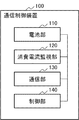
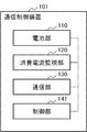
図1は、本発明の第1の実施の形態における通信制御装置100の構成を示すブロック図である。図1を参照すると、通信制御装置100は、電池部110と、消費電流監視部120と、通信部130と、制御部140と、を備える。
[First Embodiment]
FIG. 1 is a block diagram showing a configuration of a
次に、第1の実施の形態における通信制御装置100の構成について説明する。
Next, the configuration of the
電池部110は、通信制御装置100全体を稼動する電力を供給する電池を含む。また、電池部110の電池残量の取得要求を受信した場合、電池部110は、要求元に電池残量を通知する。
The
消費電流監視部120は、電池部110に接続され、少なくとも第1の通信手段を用いた通信部140の通信の場合に、通信制御装置100で消費される平均消費電流を算出する。第1の通信手段は、第1の通信を実行する手段である。
The consumption
通信部130は、第1の通信手段もしくは第2の通信手段を用いて1つ以上の通信端末と通信する。ここで、第2の通信手段は、第1の通信手段よりも低い消費電流と遅い通信速度での第2の通信を実行する通信手段である。たとえば、第1の通信手段による第1の通信は無線LAN通信、第2の通信手段による第2の通信はBLUETOOTH(登録商標)通信とする。また、通信部130は、通信終了時、通信時間を通信手段ごとに記録する。通信部130は、第3の通信手段を用いて所定の通信網にアクセスし、通信端末と所定の通信網との通信を制御するが、本実施形態の動作の説明の範囲外であるため省略する。
The
制御部140は、通信部130が記録する通信手段ごとの当日の通信時間と、消費電力監視部120が算出した当日の第1の通信手段の平均消費電流(以下、第1の通信での平均消費電流という)のデータと、を取得する。また、取得した当日の第2の通信手段の通信時間と、後述する図1に図示しない記憶部に記録された過去の第1の通信での平均消費電流の最大値と、に基づき、制御部140は、第2の通信手段を用いた通信で使用された、当日の電池部110の見做し使用容量を算出してもよい。ここで、見做し使用容量とは、第2の通信手段を用いた通信を第1の通信手段を用いて通信したと見做し、当日の第1の通信での平均消費電流のデータを用いて算出される、第2の通信で使用された推定の使用容量のことである。また、取得した第1の通信手段の通信時間(当日の通信時間)と、当日の第1の通信で消費される平均消費電流と、算出した当日の見做し使用容量に基づき、制御部140は、当日の合計の使用容量(第1及び第2の通信手段による当日の使用容量)を算出する。算出結果は、制御部140の図示しないメモリに、使用容量の履歴として記録される。
The
また、制御部140は、後述する図1に図示しない記憶部に記録された電池部110の過去の使用容量と、算出した当日の合計の使用容量と、に基づき使用容量の平均を算出し、算出された使用容量を、電池部110を充電する充電容量に決定する。制御部140は、前述の取得した通信手段ごとの通信時間と、所定の通信手段での消費電流と、算出した見做し使用容量と、当日の合計の使用容量と、使用容量の平均と、を図1に図示しない記憶部に記録する。
In addition, the
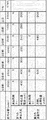
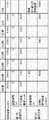
図2は、図1に図示しない記憶部に記録される表の一例である。図2を参照すると、6日前から当日までのそれぞれの日に関し、通信方法ごとの通信時間と、第1の通信で消費される平均消費電流と、見做し使用容量と、当日の合計の使用容量と、制御部140が算出する使用容量の平均と、が表形式で記録される。図2は、前述の全ての情報が1つの表に記録されたものであるが、複数の表に分散されて記録されてもよい。また、図2は、6日前から当日までのそれぞれの日に関しての情報が記録されるが、記録される日数は、使用者が任意に決定してよい。
FIG. 2 is an example of a table recorded in a storage unit (not shown in FIG. 1). Referring to FIG. 2, regarding each day from 6 days before to the current day, the communication time for each communication method, the average current consumption consumed in the first communication, the estimated usage capacity, and the total usage of the day The capacity and the average used capacity calculated by the
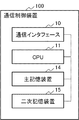
図3は、本発明の第1の実施の形態における通信制御装置100をコンピュータ装置で実現した場合のハードウェア構成例を示す図である。図3に示されるように、通信制御装置100は、それぞれ通信インタフェース10、CPU(Central Processing Unit)11、主記憶装置14、および二次記憶装置15を含む。
FIG. 3 is a diagram illustrating a hardware configuration example when the
通信インタフェース10は、処理装置および周辺端末との通信のための入出力インタフェースを構成する。また通信インタフェース10は、通信制御装置100に接続する図示しないネットワークとの接続制御のためのインタフェースも含む。具体的には、通信制御装置100の通信インタフェース10は、第1の実施の形態における通信部130として動作し、それぞれプログラム制御に基づいて各種の処理を実行する。
The
CPU11は、オペレーティングシステムを動作させて本発明の第1の実施の形態に係る通信制御装置100の全体を制御する。また、CPU11は、例えば二次記憶装置15から主記憶装置14にプログラムまたはデータを読み出す。具体的には、通信制御装置100のCPU11は、第1の実施の形態における電池部110と、消費電流監視部120と、制御部140として動作し、それぞれプログラム制御に基づいて各種の処理を実行する。また、通信制御装置100のCPU11は、1つに限らず2つ以上備えていてもよい。
The
主記憶装置14は、CPU11の制御に基づく作業用メモリである。
The
二次記憶装置15は、例えば光ディスク、フレキシブルディスク、磁気光ディスク、外付けハードディスク、または半導体メモリ等であって、コンピュータプログラムをコンピュータ読み取り可能に記録する。二次記憶装置15は、通信制御装置100が実行するためのコンピュータプログラムを一時的に記憶するまたは非一時的に記憶する。したがって、CPU11は、二次記憶装置15に記録されているコンピュータプログラムを読み込み、そのプログラムにしたがって、電池部110と、消費電流監視部120と、制御部140として動作してもよい。
The
また、コンピュータプログラムは、通信網に接続されている図示しない外部コンピュータからダウンロードされてもよい。 The computer program may be downloaded from an external computer (not shown) connected to the communication network.
なお、第1の実施の形態の説明において利用されるブロック図(図1)には、機能単位のブロックが示されている。これらの機能ブロックは、図3に示すコンピュータ装置に限らず、各部がハードウェア回路によって実現されてもよい。ただし、通信制御装置100が備える各部の実現手段は特に限定されない。すなわち、通信制御装置100は、物理的に結合した1つの装置により実現されてもよいし、物理的に分離した2つ以上の装置を有線または無線で接続し、これら複数の装置により実現されてもよい。
The block diagram (FIG. 1) used in the description of the first embodiment shows functional unit blocks. These functional blocks are not limited to the computer apparatus shown in FIG. 3, and each unit may be realized by a hardware circuit. However, the means for realizing each unit included in the
以上のように構成された通信制御装置100の動作について、図4、図5、図6のフローチャートを参照して説明する。
The operation of the
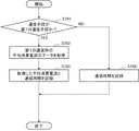
図4は、第1の実施の形態における通信制御装置100での通信時間および平均消費電流の記録の動作の概要を示すフローチャートである。尚、このフローチャートによる処理は、前述したCPUによるプログラム制御に基づいて、実行されても良い。
FIG. 4 is a flowchart showing an outline of the operation of recording the communication time and the average current consumption in the
図4に示すように、まず、通信部130が通信端末との通信を終了した場合、制御部110は、通信端末との通信の通信手段が第1の通信手段か否かを確認する(ステップS101)。もし通信手段が第1の通信手段であった場合(ステップS101でYES)、制御部140は、第1の通信時の平均消費電流のデータを消費電流監視部120から取得する(ステップS102)。次に、制御部140は、取得した平均消費電流と通信時間を、図1に図示しない記憶部に記録する(ステップS103)。もし通信手段が第2の通信手段であった場合(ステップS101でNO)、制御部140は、通信時間を、図1に図示しない記憶部に記録する(ステップS104)。
As shown in FIG. 4, first, when the
以上で、通信制御装置100は、通信時間および平均消費電流の記録の動作を終了する。
Thus, the
図5および図6は、第1の実施の形態における通信制御装置100での電池部110の充電容量の決定の動作の概要を示すフローチャートである。尚、このフローチャートによる処理も、前述したCPUによるプログラム制御に基づいて、実行されても良い。
5 and 6 are flowcharts showing an outline of the operation of determining the charge capacity of the
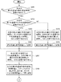
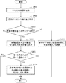
図5および図6に示すように、まず、電池部110の充電開始時、制御部140は、図1に図示しない記憶部、または主記憶装置14に記録された表(図2)を参照し、当日の第2の通信手段の通信時間に記録があるか否かを確認する(ステップS201)。もし記録がある場合(ステップS201でYES)、制御部140は、表中に当日の第1の通信での平均消費電流に記録があるか否かを確認する(ステップS202)。記録がある場合(ステップS202でYES)、制御部140は、当日の第2の通信手段の通信時間と、当日の第1の通信での平均消費電流とを参照し、それらを掛け合わせる(ステップS203)。次に、制御部140は、ステップS203の解を、当日の第2の通信手段の通信により使用された見做し使用容量として表に記録する(ステップS204)。図2の表の場合、制御部140は、当日の第2の通信手段の通信時間の1(h)と、当日の第1の通信での平均消費電流の200(mA)とを掛け合わせた解の200(mAh)を表に記録する。表中に当日の第1の通信での平均消費電流の記録が無い場合(ステップS202でNO)、制御部140は、当日の第2の通信手段の通信時間と、表中の第1の通信での平均消費電流の最大値とを参照し、それらを掛け合わせる(ステップS205)。次に、制御部140は、ステップS205の解を、当日の第2の通信手段の通信により使用された見做し使用容量として表に記録する(ステップS206)。
As shown in FIGS. 5 and 6, first, when charging of the
次に、制御部140は、表中の当日の第1の通信での平均消費電流と、当日の第1の通信手段の通信時間とを参照し、それらを掛け合わせる(ステップS207)。図2の表の場合、制御部140は、表中の当日の第1の通信での平均消費電流の200(mA)と、当日の第1の通信手段の通信時間の6(h)とを掛け合わせ、解として1200(mAh)を得る。
Next, the
次に、制御部140は、表中の当日の第2の通信手段の見做し使用容量と、ステップS207の解とを足し合わせ、当日の合計の使用容量として表に記録する(ステップS208)。表中の当日の第2の通信手段の見做し使用容量が空欄であれば、制御部140は、ステップS207の解をそのまま当日の合計の使用容量として表に記録する。図2の表の場合、制御部140は、ステップS207の解である1200(mAh)と、表中の当日の第2の通信手段の見做し使用容量の200(mA)を足し合わせた解である1400(mAh)を当日の合計の使用容量として表に記録する。
Next, the
次に、制御部140は、表中の合計の使用容量が全ての日数分記録されているか否か確認する(ステップS209)。全ての日数分記録されている場合(ステップS209でYES)、制御部140は、当日以外の6日間の使用容量の平均を算出し、10倍した後、当日の使用容量を足し、11で割った解を平均使用容量として記録する(ステップS210)。全ての日数分記録されていない場合(ステップS209でNO)、制御部140は、電池部110から満充電容量を取得し、平均使用容量として記録する(ステップS211)。
Next, the
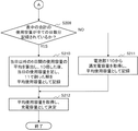
次に、制御部140は、表中の平均使用容量を取得し、充電容量として決定する(ステップS212)。図2の表の場合、制御部140は、当日以外の6日間の使用容量の平均を算出し、解として1797(mAh)を得る。次に、制御部140は、解である1797(mAh)の10倍である17970(mAh)に当日の使用容量の1400(mAh)を足し、11で割った解である1761(mAh)を平均使用容量として記録する。ここで、使用容量の平均をいったん10倍し、当日の使用容量を加えた後に10+1である11で割っているのは、充電容量の決定において、当日の使用容量の影響を小さくするためである。使用容量の平均を掛け合わせる値は、使用者が任意に決定してよい。また、制御部140は、当日の使用容量の影響を考慮せず、表中に記録される当日までの全ての日数分の平均を算出し、平均使用容量として記録してもよい。
Next, the
以上で、通信制御装置100は、電池部110の充電容量の決定の動作を終了する。その後、電池部110は、決定された充電容量の分だけ電池を充電するようにすればよい。
As described above, the
次に、本発明の第1の実施の形態の効果について説明する。 Next, effects of the first exemplary embodiment of the present invention will be described.
上述した本実施形態における通信制御装置100は、電池部の満充電を回避し、劣化を抑制できる。
The
その理由は、以下のような構成を含むからである。即ち、第1に制御部140は、当日の合計の使用容量を記録する。第2に、制御部140は、記録された過去の使用容量の平均と当日の使用容量に基づき充電容量を決定する。これにより、通信制御装置100は、使用する容量を記録された過去の使用容量から推測し、その結果に基づき充電することができる。したがって、電池劣化の原因となる電池部110の満充電を回避し、電池部110の劣化を抑制できるという効果が得られる。
This is because the following configuration is included. That is, first, the
[第2の実施形態]
次に、本発明の第2の実施形態について図面を参照して詳細に説明する。以下、本実施形態の説明が不明確にならない範囲で、前述の説明と重複する内容については説明を省略する。
[Second Embodiment]
Next, a second embodiment of the present invention will be described in detail with reference to the drawings. Hereinafter, the description overlapping with the above description is omitted as long as the description of the present embodiment is not obscured.
図7は、本発明の第2の実施形態に係る通信制御装置101の構成を示すブロック図である。
FIG. 7 is a block diagram showing the configuration of the
図7を参照すると、本実施形態における通信制御装置101は、第1の実施形態のそれと比べて、制御部140の代わりに制御部141を備える。
Referring to FIG. 7, the
制御部141は、第1の実施形態における制御部140の機能に加えて、第1の通信手段を用いた通信部140の通信中に電池部110の電池残量と消費電流監視部120の平均消費電流を取得する。制御部141は、取得した情報から残り稼動時間を算出する。制御部141は、算出した残り稼動時間に基づき、通信部130の通信手段を第1の通信手段から第2の通信手段に切り替えるよう制御する。
In addition to the function of the
図8は、第2の実施の形態における通信制御装置101での通信部130の通信手段の切り替えの動作の概要を示すフローチャートである。尚、このフローチャートによる処理も、前述したCPUによるプログラム制御に基づいて、実行されても良い。
FIG. 8 is a flowchart showing an outline of the operation of switching the communication means of the
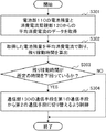
図8に示すように、まず、通信部130が第1の通信手段を用いた通信中、制御部141は、電池部110の電池残量(mAh)と消費電流監視部120からの平均消費電流(mA)のデータを取得する(ステップS301)。
As shown in FIG. 8, first, during communication using the first communication means by the
次に、制御部141は、取得した電池残量(mAh)を平均消費電流(mA)で割り、残り稼動時間(h)を算出する(ステップS302)。もし残り稼動時間(h)が所定の時間を下回っている場合(ステップS303でYES)、制御部141は、通信部130の通信手段を第1の通信手段から第2の通信手段に切り替えるよう制御する(ステップS304)。
Next, the
以上で、通信制御装置101は、通信部130の通信手段の切り替えの動作を終了する。
Thus, the
次に、本発明の第2の実施の形態の効果について説明する。 Next, effects of the second exemplary embodiment of the present invention will be described.
上述した本実施形態における通信制御装置101は、使用容量を削減し稼働時間を延長できる。
The
その理由は、以下のような構成を含むからである。即ち、第1に制御部141は、電池残量と平均消費電流を取得した結果に基づき、残り稼動時間を算出する。第2に、制御部141は、算出した残り稼動時間(h)が所定の時間を下回っている場合、通信部130の通信手段を第1の通信手段から第2の通信手段に切り替える。なお、所定の時間は使用者が任意に設定できる。第2の通信手段は、第1の通信手段よりも低い消費電流で通信する通信手段であるので、通信制御装置101は、使用容量を削減し稼働時間を延長できるという効果が得られる。
This is because the following configuration is included. That is, first, the
[第3の実施形態]
次に、本発明の第3の実施形態について図面を参照して詳細に説明する。以下、本実施形態の説明が不明確にならない範囲で、前述の説明と重複する内容については説明を省略する。
[Third Embodiment]
Next, a third embodiment of the present invention will be described in detail with reference to the drawings. Hereinafter, the description overlapping with the above description is omitted as long as the description of the present embodiment is not obscured.
図9は、本発明の第3の実施形態に係る通信制御装置102の構成を示すブロック図である。
FIG. 9 is a block diagram showing the configuration of the
図9を参照すると、本実施形態における通信制御装置102は、第1の実施形態のそれと比べて、制御部140の代わりに制御部142を備え、通信部130の代わりに通信部132を備える。
Referring to FIG. 9, the
通信部132は、第1の実施形態における通信部130の機能に加えて、通信量の取得要求を受信した場合、要求元に受信時の通信手段における通信量を通知する。通知する通信量は、1日あたりの通信量でも1ヶ月あたりの通信量でもよい。通信量の単位時間は、使用者が任意に設定できる。
In addition to the function of the
制御部142は、第1の実施形態における制御部140の機能に加えて、電池部110の充電開始時、通信部132から通信量を取得する。取得した通信量が所定の通信量を上回った場合、制御部142は、充電容量を図8に図示しない記憶部に記録される所定の通信切り替え用使用容量に変更する。所定の通信量および所定の通信切り替え用使用容量は、使用者が任意に設定できる。所定の通信切り替え用使用容量は、図1に図示しない記憶部に記録される平均使用容量よりも低く設定する。また、通信部132が第1の通信手段を用いた通信中の場合、制御部142は、通信部132の通信手段を第1の通信手段から第2の通信手段に切り替えるよう制御する。
In addition to the function of the
図10は、図9に図示しない記憶部に記録される表の一例である。図10を参照すると、第1の実施形態における図1に図示しない記憶部に記録される表の要素に加えて、通信切り替え使用容量が表に記録される。前述の通り、記録される通信切り替え用使用容量は、使用者が任意に設定できる。 FIG. 10 is an example of a table recorded in a storage unit (not shown in FIG. 9). Referring to FIG. 10, in addition to the table elements recorded in the storage unit (not shown in FIG. 1) in the first embodiment, the communication switching usage capacity is recorded in the table. As described above, the communication switching use capacity to be recorded can be arbitrarily set by the user.
図11は、第3の実施の形態における通信制御装置102での電池部110の充電容量の決定および通信部130の通信手段の切り替えの動作の概要を示すフローチャートである。尚、このフローチャートによる処理も、前述したCPUによるプログラム制御に基づいて、実行されても良い。
FIG. 11 is a flowchart illustrating an outline of operations for determining the charging capacity of the
図11に示すように、まず、電池部110の充電開始時、制御部142は、第1の実施形態におけるステップS201〜S211の処理を実施し、平均使用容量を記録する(ステップS401)。
As shown in FIG. 11, first, at the start of charging of the
次に、制御部142は、通信部132から通信量を取得し(ステップS402)、所定の通信量を上回っているか否か確認する(ステップS403)。取得した通信量が所定の通信量を上回っている場合(ステップS403でYES)、制御部142は、充電容量を図8に図示しない記憶部に記録される所定の通信切り替え用使用容量に決定する(ステップS404)。次に、通信部132が第1の通信手段を用いた通信中の場合(ステップS405でYES)、制御部142は、通信部132の通信手段を第1の通信手段から第2の通信手段に切り替えるよう制御する(ステップS406)。取得した通信量が所定の通信量を上回っていない場合(ステップS403でNO)、制御部142は、第1の実施形態におけるステップS212の処理と同様、表中の平均使用容量を取得し、充電容量として決定する(ステップS407)。
Next, the
以上で、通信制御装置102は、電池部110の充電容量の決定および通信部132の通信手段の切り替えの動作を終了する。
Thus, the
次に、本発明の第3の実施の形態の効果について説明する。 Next, effects of the third exemplary embodiment of the present invention will be described.
上述した本実施形態における通信制御装置102は、さらに電池部の劣化を抑制できる。
The
その理由は、以下のような構成を含むからである。即ち、第1に制御部142は、通信部132から通信量を取得し、所定の通信量を上回っているか確認する。第2に、取得した通信量が所定の通信量を上回っている場合、制御部142は、充電容量を所定の通信切り替え用使用容量に決定する。第3に、制御部142は、通信部132の通信手段を第1の通信手段から第2の通信手段に切り替えるよう制御する。前述の通り、制御部142は、第3の通信手段を用いて所定の通信網にアクセスし、通信端末と所定の通信網との通信を制御する。このとき、第3の通信手段が通信量に基づき通信制限を行う場合、通信制御装置102は、通信端末の通信速度が第1の通信手段ではなく第3の通信手段の通信速度に制限されることがある。したがって、通信量が所定の通信量を上回っている場合、制御部142は、あらかじめ通信部132の通信手段を第1の通信手段から第2の通信手段に切り替える。また、制御部142は、通信手段が第1の通信手段から消費電流の低い第2の通信手段に切り替えられるため、充電容量を平均使用容量よりも低い所定の通信切り替え用使用容量に決定する。このようにして、制御部142は、通信量に基づいて通信部130の通信手段を切り替え、電池部110の充電容量を決定できるので、通信制御装置101は、さらに電池部の劣化を抑制できるという効果が得られる。
This is because the following configuration is included. That is, first, the
以上説明した、本発明の各実施形態における各構成要素は、その機能をハードウェア的に実現することはもちろん、プログラム制御に基づくコンピュータ装置、ファームウェアで実現することができる。プログラムは、磁気ディスクや半導体メモリなどのコンピュータ可読記録媒体に記録されて提供され、コンピュータの立ち上げ時などにコンピュータに読み取られる。この読み取られたプログラムは、そのコンピュータの動作を制御することにより、そのコンピュータを前述した各実施の形態における構成要素として機能させる。 Each component in each embodiment of the present invention described above can be realized by a computer apparatus and firmware based on program control as well as by realizing the function in hardware. The program is provided by being recorded on a computer-readable recording medium such as a magnetic disk or a semiconductor memory, and is read by the computer when the computer is started up. The read program causes the computer to function as a component in each of the embodiments described above by controlling the operation of the computer.
以上、各実施の形態を参照して本発明を説明したが、本発明は上記実施の形態に限定されるものではない。本発明の構成や詳細には、本発明のスコープ内で当業者が理解しえる様々な変更をすることができる。 Although the present invention has been described with reference to each embodiment, the present invention is not limited to the above embodiment. Various changes that can be understood by those skilled in the art can be made to the configuration and details of the present invention within the scope of the present invention.
たとえば、以上の各実施形態で説明した各構成要素は、必ずしも個々に独立した存在である必要はない。例えば、各構成要素は、複数の構成要素が1個のモジュールとして実現されたり、一つの構成要素が複数のモジュールで実現されたりしてもよい。また、各構成要素は、ある構成要素が他の構成要素の一部であったり、ある構成要素の一部と他の構成要素の一部とが重複していたり、といったような構成であってもよい。 For example, each component described in each of the above embodiments does not necessarily have to be individually independent. For example, for each component, a plurality of components may be realized as one module, or one component may be realized as a plurality of modules. Each component is configured such that a component is a part of another component, or a part of a component overlaps a part of another component. Also good.
また、以上説明した各実施形態では、複数の動作をフローチャートの形式で順番に記載してあるが、その記載の順番は複数の動作を実行する順番を限定するものではない。このため、各実施形態を実施するときには、その複数の動作の順番は内容的に支障しない範囲で変更することができる。 Further, in each of the embodiments described above, a plurality of operations are described in order in the form of a flowchart, but the described order does not limit the order in which the plurality of operations are executed. For this reason, when each embodiment is implemented, the order of the plurality of operations can be changed within a range that does not hinder the contents.
さらに、以上説明した各実施形態では、複数の動作は個々に相違するタイミングで実行されることに限定されない。例えば、ある動作の実行中に他の動作が発生したり、ある動作と他の動作との実行タイミングが部分的に乃至全部において重複していたりしていてもよい。 Furthermore, in each embodiment described above, a plurality of operations are not limited to being executed at different timings. For example, another operation may occur during the execution of a certain operation, or the execution timing of a certain operation and another operation may partially or entirely overlap.
さらに、以上説明した各実施形態では、ある動作が他の動作の契機になるように記載しているが、その記載はある動作と他の動作の全ての関係を限定するものではない。このため、各実施形態を実施するときには、その複数の動作の関係は内容的に支障のない範囲で変更することができる。また各構成要素の各動作の具体的な記載は、各構成要素の各動作を限定するものではない。このため、各構成要素の具体的な各動作は、各実施形態を実施する上で機能的、性能的、その他の特性に対して支障をきたさない範囲内で変更されて良い。 Furthermore, in each of the embodiments described above, a certain operation is described as a trigger for another operation, but the description does not limit all relationships between the certain operation and the other operations. For this reason, when each embodiment is implemented, the relationship between the plurality of operations can be changed within a range that does not hinder the contents. The specific description of each operation of each component does not limit each operation of each component. For this reason, each specific operation | movement of each component may be changed in the range which does not cause trouble with respect to a functional, performance, and other characteristic in implementing each embodiment.
10 通信インタフェース
11 CPU
14 主記憶装置
15 二次記憶装置
100、101、102 通信制御装置
110 電池部
120 消費電流監視部
130、132 通信部
140、141、142 制御部
10
14
Claims (10)
第1の通信手段もしくは第2の通信手段を用いて通信端末と通信する通信部と、
少なくとも前記第1の通信手段を用いた前記通信部の通信で消費する平均消費電流を算出する消費電流監視部と、
通信手段ごとに前記通信端末と通信する通信時間と、前記消費電力監視部が算出した前記第1の通信手段を用いた前記通信部の通信で消費した消費電流を取得した結果に基づき、当日の合計の消費電力を算出し、その結果に基づき、前記電池部を充電する充電容量を決定する制御部と
を備える通信制御装置。 A battery unit for supplying power for operating the entire communication control device;
A communication unit that communicates with the communication terminal using the first communication means or the second communication means;
A current consumption monitoring unit that calculates an average current consumption consumed in communication of the communication unit using at least the first communication unit;
Based on the communication time for communicating with the communication terminal for each communication means, and the result of obtaining the current consumption consumed in the communication of the communication unit using the first communication means calculated by the power consumption monitoring unit, And a control unit that calculates a total power consumption and determines a charge capacity for charging the battery unit based on the result.
算出した稼動残り時間が所定の時間を下回った場合、前記制御部が前記通信部の通信手段を前記第1の通信手段から前記第2の通信手段に切り替えるよう制御する請求項1または2に記載の通信制御装置。 When the communication unit communicates with the communication terminal using the first communication unit, the control unit operates based on the average current consumption acquired from the current consumption monitoring unit and the remaining battery level acquired from the battery unit. Calculate the remaining time,
The control unit controls the communication unit of the communication unit to switch the communication unit of the communication unit from the first communication unit to the second communication unit when the calculated remaining operation time is less than a predetermined time. Communication control device.
取得した前記通信量が所定の通信量を上回った場合、前記充電容量を所定の使用容量に決定する請求項1ないし3のいずれか1項に記載の通信制御装置。 The control unit further acquires a communication amount from the communication unit,
The communication control apparatus according to any one of claims 1 to 3, wherein when the acquired communication amount exceeds a predetermined communication amount, the charging capacity is determined as a predetermined usage capacity.
算出した前記稼動残り時間が所定の時間を下回った場合、通信手段を前記第1の通信手段から前記第2の通信手段に切り替えるよう制御する請求項5または6に記載の通信制御装置の制御方法。 When communicating with the communication terminal using the first communication means, obtain the average current consumption during communication in the first communication means and the remaining battery level of the battery unit, calculate the remaining operation time,
The control method of the communication control device according to claim 5 or 6, wherein when the calculated remaining operation time is less than a predetermined time, the communication unit is controlled to be switched from the first communication unit to the second communication unit. .
取得した前記通信量が所定の通信量を上回った場合、前記充電容量を所定の使用容量に決定し、通信手段を前記第1の通信手段から前記第2の通信手段に切り替えるよう制御する請求項5ないし7のいずれか1項に記載の通信制御装置の制御方法。 Get traffic,
The control unit determines that the charging capacity is a predetermined usage capacity when the acquired communication amount exceeds a predetermined communication amount, and switches the communication unit from the first communication unit to the second communication unit. The control method of the communication control apparatus according to any one of 5 to 7.
Priority Applications (1)
| Application Number | Priority Date | Filing Date | Title |
|---|---|---|---|
| JP2016000854A JP6636805B2 (en) | 2016-01-06 | 2016-01-06 | Communication control device, communication control device control method, and program |
Applications Claiming Priority (1)
| Application Number | Priority Date | Filing Date | Title |
|---|---|---|---|
| JP2016000854A JP6636805B2 (en) | 2016-01-06 | 2016-01-06 | Communication control device, communication control device control method, and program |
Publications (2)
| Publication Number | Publication Date |
|---|---|
| JP2017123714A true JP2017123714A (en) | 2017-07-13 |
| JP6636805B2 JP6636805B2 (en) | 2020-01-29 |
Family
ID=59306695
Family Applications (1)
| Application Number | Title | Priority Date | Filing Date |
|---|---|---|---|
| JP2016000854A Active JP6636805B2 (en) | 2016-01-06 | 2016-01-06 | Communication control device, communication control device control method, and program |
Country Status (1)
| Country | Link |
|---|---|
| JP (1) | JP6636805B2 (en) |
Cited By (1)
| Publication number | Priority date | Publication date | Assignee | Title |
|---|---|---|---|---|
| JP2023094211A (en) * | 2021-12-23 | 2023-07-05 | ダイキン工業株式会社 | communication adapter |
Citations (6)
| Publication number | Priority date | Publication date | Assignee | Title |
|---|---|---|---|---|
| JP2000232683A (en) * | 1999-02-10 | 2000-08-22 | Denso Corp | Radio communication apparatus |
| JP2003069699A (en) * | 2001-08-28 | 2003-03-07 | Canon Inc | Wireless communication device, control method thereof, and control program |
| JP2007201732A (en) * | 2006-01-25 | 2007-08-09 | Nakayo Telecommun Inc | Portable terminal having battery status display function |
| JP2009207281A (en) * | 2008-02-27 | 2009-09-10 | Kyocera Corp | Electronics |
| US20090289603A1 (en) * | 2008-05-21 | 2009-11-26 | Apple Inc. | Method and apparatus for maintaining a battery in a partially charged state |
| WO2011018959A1 (en) * | 2009-08-11 | 2011-02-17 | ソニー株式会社 | Electronic device, method for charging electronic device, program, charging control device, and charging control method |
-
2016
- 2016-01-06 JP JP2016000854A patent/JP6636805B2/en active Active
Patent Citations (6)
| Publication number | Priority date | Publication date | Assignee | Title |
|---|---|---|---|---|
| JP2000232683A (en) * | 1999-02-10 | 2000-08-22 | Denso Corp | Radio communication apparatus |
| JP2003069699A (en) * | 2001-08-28 | 2003-03-07 | Canon Inc | Wireless communication device, control method thereof, and control program |
| JP2007201732A (en) * | 2006-01-25 | 2007-08-09 | Nakayo Telecommun Inc | Portable terminal having battery status display function |
| JP2009207281A (en) * | 2008-02-27 | 2009-09-10 | Kyocera Corp | Electronics |
| US20090289603A1 (en) * | 2008-05-21 | 2009-11-26 | Apple Inc. | Method and apparatus for maintaining a battery in a partially charged state |
| WO2011018959A1 (en) * | 2009-08-11 | 2011-02-17 | ソニー株式会社 | Electronic device, method for charging electronic device, program, charging control device, and charging control method |
Cited By (2)
| Publication number | Priority date | Publication date | Assignee | Title |
|---|---|---|---|---|
| JP2023094211A (en) * | 2021-12-23 | 2023-07-05 | ダイキン工業株式会社 | communication adapter |
| JP7518396B2 (en) | 2021-12-23 | 2024-07-18 | ダイキン工業株式会社 | Communication Adapter |
Also Published As
| Publication number | Publication date |
|---|---|
| JP6636805B2 (en) | 2020-01-29 |
Similar Documents
| Publication | Publication Date | Title |
|---|---|---|
| JP6486916B2 (en) | Battery charging based on intelligent context | |
| KR102561386B1 (en) | Mechanism for extending cycle life of a battery | |
| JP2020501482A (en) | Wireless battery management system and battery pack including the same | |
| EP3014740B1 (en) | Power transmitting apparatus, control method for power transmitting apparatus, and recording medium storing program | |
| WO2018201874A1 (en) | Method and network site device for adjusting terminal capability and terminal | |
| CN102750248A (en) | USB (Universal Serial Bus) equipment working mode switching method and USB equipment | |
| CN104780269A (en) | A method and device for adjusting the performance of a mobile terminal based on power | |
| KR102877560B1 (en) | Electronic apparatus and charging method thereof | |
| KR20150000675A (en) | Method for charging battery and an electronic device thereof | |
| JP2016099926A (en) | Control system and control method of communication apparatus | |
| KR20210149590A (en) | System and method for physical downlink control channel monitoring based on user equipment capability in dual connectivity | |
| EP3537847A1 (en) | Method and device for power outage handling and acquiring connection relations | |
| WO2015113461A1 (en) | Power adapter and terminal | |
| JPWO2017085920A1 (en) | Charging device and electronic device | |
| EP4161230A1 (en) | Heat dissipation method and apparatus for electronic device, and storage medium | |
| CN112701738A (en) | Charging method, charging device and electronic equipment | |
| JP6636805B2 (en) | Communication control device, communication control device control method, and program | |
| US20200249735A1 (en) | Charge control apparatus and charge control system | |
| KR20210043337A (en) | Electronic device for controlling power switching mode and operating method thereof | |
| JP5733042B2 (en) | Femtocell radio base station, communication control method and program | |
| WO2017219552A1 (en) | Charging method and device, and storage medium | |
| JP7627877B2 (en) | Battery Management System | |
| JP2014165671A (en) | Mobile communication system, center device, control method and program | |
| JP6558808B2 (en) | Control device, electronic device, control method, and control program | |
| JP2005115620A (en) | Task management method and electronic device having task management means |
Legal Events
| Date | Code | Title | Description |
|---|---|---|---|
| A621 | Written request for application examination |
Free format text: JAPANESE INTERMEDIATE CODE: A621 Effective date: 20181214 |
|
| A977 | Report on retrieval |
Free format text: JAPANESE INTERMEDIATE CODE: A971007 Effective date: 20190912 |
|
| A131 | Notification of reasons for refusal |
Free format text: JAPANESE INTERMEDIATE CODE: A131 Effective date: 20190917 |
|
| A521 | Request for written amendment filed |
Free format text: JAPANESE INTERMEDIATE CODE: A523 Effective date: 20191009 |
|
| TRDD | Decision of grant or rejection written | ||
| A01 | Written decision to grant a patent or to grant a registration (utility model) |
Free format text: JAPANESE INTERMEDIATE CODE: A01 Effective date: 20191126 |
|
| A61 | First payment of annual fees (during grant procedure) |
Free format text: JAPANESE INTERMEDIATE CODE: A61 Effective date: 20191219 |
|
| R150 | Certificate of patent or registration of utility model |
Ref document number: 6636805 Country of ref document: JP Free format text: JAPANESE INTERMEDIATE CODE: R150 |