JP2017123701A - Motor maintenance device and motor system - Google Patents
Motor maintenance device and motor system Download PDFInfo
- Publication number
- JP2017123701A JP2017123701A JP2016000080A JP2016000080A JP2017123701A JP 2017123701 A JP2017123701 A JP 2017123701A JP 2016000080 A JP2016000080 A JP 2016000080A JP 2016000080 A JP2016000080 A JP 2016000080A JP 2017123701 A JP2017123701 A JP 2017123701A
- Authority
- JP
- Japan
- Prior art keywords
- motor
- temperature
- value
- phase
- abnormality
- Prior art date
- Legal status (The legal status is an assumption and is not a legal conclusion. Google has not performed a legal analysis and makes no representation as to the accuracy of the status listed.)
- Pending
Links
Images


Landscapes
- Control Of Ac Motors In General (AREA)
Abstract
【課題】モータの異常を確実に感知することができるモータの保全装置を提供する。
【解決手段】モータの保全装置は、モータの動作状況に応じて変化するパラメータを入力として前記モータの動作中に前記モータの一部における温度の推定値を演算する推定部と、前記モータの一部における温度の測定値の入力を温度測定器から受け付け、前記モータの一部における温度の推定値の入力を前記推定部から受け付け、前記モータの一部における温度の測定値と推定値との比較結果に基づいて前記モータの異常を感知する感知部と、を備えた。
【選択図】図1A motor maintenance device capable of reliably detecting a motor abnormality is provided.
An apparatus for maintaining a motor includes an estimation unit that calculates an estimated value of a temperature of a part of the motor during operation of the motor by using a parameter that changes according to an operation state of the motor as an input. An input of a temperature measurement value at a part is received from a temperature measuring device, an input of an estimated value of a temperature at a part of the motor is received from the estimation part, and a comparison between the measured value of the temperature at a part of the motor and the estimated value And a sensing unit for sensing an abnormality of the motor based on the result.
[Selection] Figure 1
Description
この発明は、モータの保全装置およびモータシステムに関する。 The present invention relates to a motor maintenance device and a motor system.
特許文献1は、モータの温度推定装置を開示する。当該温度推定装置は、数式で表された温度モデルに基づいてモータの温度を推定する。この際の数式は、抵抗、インダクタンス、磁束、電圧、電流といった電気的な要素を主なパラメータとする。
特許文献1に記載の温度推定装置において、温度モデルは、モータの内部の物理的な構造の情報に基づいていない。このため、モータの温度を正確に測定することができない。その結果、モータの異常の感知を適切に行うことができない。
In the temperature estimation device described in
この発明は、上述の課題を解決するためになされた。この発明の目的は、モータの異常を確実に感知することができるモータの保全装置およびモータシステムを提供することである。 The present invention has been made to solve the above-described problems. An object of the present invention is to provide a motor maintenance device and a motor system capable of reliably detecting an abnormality of a motor.
この発明に係るモータの保全装置は、モータの動作状況に応じて変化するパラメータを入力として前記モータの動作中に前記モータの一部における温度の推定値を演算する推定部と、前記モータの一部における温度の測定値の入力を温度測定器から受け付け、前記モータの一部における温度の推定値の入力を前記推定部から受け付け、前記モータの一部における温度の測定値と推定値との比較結果に基づいて前記モータの異常を感知する感知部と、を備えた。 A motor maintenance device according to the present invention comprises: an estimation unit that calculates an estimated value of a temperature of a part of the motor during operation of the motor by using a parameter that changes according to an operation state of the motor; An input of a temperature measurement value at a part is received from a temperature measuring device, an input of an estimated value of a temperature at a part of the motor is received from the estimation part, and a comparison between the measured value of the temperature at a part of the motor and the estimated value And a sensing unit for sensing an abnormality of the motor based on the result.
この発明に係るモータシステムは、動作状況に応じて温度を変化させるモータと、前記モータの一部における温度の測定値の入力を温度測定器から受け付け、前記モータの動作状況に応じて変化するパラメータを入力として前記モータの動作中に前記モータの一部における温度の推定値を演算し、前記モータの一部における温度の測定値と推定値との比較結果に基づいて前記モータの異常を感知する保全装置と、を備えた。 A motor system according to the present invention is a parameter that changes a temperature according to an operating state of the motor, and receives a temperature measurement value input from a temperature measuring device at a part of the motor, and changes according to the operating state of the motor. Is used to calculate an estimated value of the temperature of a part of the motor during operation of the motor, and an abnormality of the motor is detected based on a comparison result between the measured value of the temperature of the part of the motor and the estimated value. And a maintenance device.
これらの発明によれば、モータの異常は、モータの一部における温度の測定値と推定値との比較結果に基づいて感知される。このため、モータの異常を確実に感知することができる。 According to these inventions, the abnormality of the motor is detected based on the comparison result between the measured value and the estimated value of the temperature in a part of the motor. For this reason, abnormality of a motor can be detected reliably.
この発明を実施するための形態について添付の図面に従って説明する。なお、各図中、同一又は相当する部分には同一の符号が付される。当該部分の重複説明は適宜に簡略化ないし省略する。 A mode for carrying out the invention will be described with reference to the accompanying drawings. In addition, the same code | symbol is attached | subjected to the part which is the same or it corresponds in each figure. The overlapping explanation of the part is appropriately simplified or omitted.
実施の形態1.
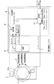
図1はこの発明の実施の形態1におけるモータシステムの構成図である。
FIG. 1 is a configuration diagram of a motor system according to
図1に示すように、モータシステムは、モータ1と周囲温度測定器2とR相巻線温度測定器3とS相巻線温度測定器4とT相巻線温度測定器5と駆動制御システム6とを備える。
As shown in FIG. 1, the motor system includes a
例えば、モータ1は、圧延ラインに設けられる。例えば、モータ1は、三相誘導電動機である。モータ1が三相誘導電動機の場合、モータ1は、R相とS相とT相とを備える。
For example, the
周囲温度測定器2は、モータ1の周囲に設けられる。R相巻線温度測定器3は、モータ1のR相の巻線に設けられる。S相巻線温度測定器4は、モータ1のS相の巻線に設けられる。T相巻線温度測定器5は、モータ1のT相の巻線に設けられる。
The ambient
駆動制御システム6は、ドライブ装置7と保全装置8とを備える。
The
ドライブ装置7の出力部は、モータ1の入力部に接続される。
The output unit of the
保全装置8は、推定部9と感知部10とを備える。
The
推定部9の入力部は、周囲温度測定器2の出力部とドライブ装置7の出力部とに接続される。感知部10の入力部は、R相巻線温度測定器3の出力部とS相巻線温度測定器4の出力部とT相巻線温度測定器5の出力部と推定部9の出力部とに接続される。
The input unit of the
モータシステムにおいて、ドライブ装置7は、R相の主回路とS相の主回路とT相の主回路とに流れる電流を制御することによりモータ1の回転を制御する。モータ1の温度はモータ1の動作状況に応じて変化する。
In the motor system, the
この際、ドライブ装置7は、R相の電圧の設定値VRを出力する。ドライブ装置7は、S相の電圧の設定値VSを出力する。ドライブ装置7は、T相の電圧の設定値VTを出力する。ドライブ装置7は、R相の電流の設定値IRを出力する。ドライブ装置7は、S相の電流の設定値ISを出力する。ドライブ装置7は、T相の電流の設定値ITを出力する。ドライブ装置7は、周波数の設定値fを出力する。
In this case, the
周囲温度測定器2は、モータ1の周囲の温度を測定する。周囲温度測定器2は、モータ1の周囲温度の測定値Tambを出力する。R相巻線温度測定器3は、R相の巻線の温度を測定する。R相巻線温度測定器3は、R相の巻線の温度の測定値T1Rを出力する。S相巻線温度測定器4は、S相の巻線の温度を測定する。S相巻線温度測定器4は、S相の巻線の温度の測定値T1Sを出力する。T相巻線温度測定器5は、T相の巻線の温度を測定する。T相巻線温度測定器5は、T相の巻線の温度の測定値T1Tを出力する。
The ambient temperature measuring
保全装置8において、推定部9は、モータ1の周囲温度の測定値Tambの入力を周囲温度測定器2から受け付ける。推定部9は、R相の電圧の設定値VRとS相の電圧の設定値VSとT相の電圧の設定値VTとR相の電流の設定値IRとS相の電流の設定値ISとT相の電流の設定値ITと周波数の設定値fとの入力をドライブ装置7から受け付ける。
In the
推定部9は、モータ1の周囲温度の測定値TambとR相の電圧の設定値VRとS相の電圧の設定値VSとT相の電圧の設定値VTとR相の電流の設定値IRとS相の電流の設定値ISとT相の電流の設定値ITと周波数の設定値fとに基づいて各相の巻線の温度の推定値T2を演算する。具体的には、推定部9は、各相の巻線の温度の推定値T2としてR相の巻線の温度の推定値T2RとS相の巻線の温度の推定値T2SとT相の巻線の温度の推定値T2Tとをオンライン温度モデルを用いて演算する。
Estimating
保全装置8において、感知部10は、各相の巻線における温度の測定値T1の入力をR相巻線温度測定器3とS相巻線温度測定器4とT相巻線温度測定器5とから受け付ける。具体的には、感知部10は、各相の巻線における温度の測定値T1としてR相の巻線の温度の測定値T1RとS相の巻線の温度の測定値T1SとT相の巻線の温度の測定値T1Tとの入力を受け付ける。
In the
感知部10は、各相の巻線における温度の推定値T2の入力を推定部9から受け付ける。具体的には、感知部10は、各相の巻線における温度の推定値T2の入力としてR相の巻線の温度の推定値T2RとS相の巻線の温度の推定値T2SとT相の巻線の温度の推定値T2Tとの入力を受け付ける。
The
感知部10は、各相の巻線の温度の測定値T1と推定値T2とを比較する。感知部10は、各相の巻線の温度の測定値T1と推定値T2との比較結果に基づいてモータ1の異常を感知する。
The
具体的には、感知部10は、R相の巻線の温度の測定値T1Rと推定値T2Rとの比較結果に基づいてR相の異常を感知する。例えば、感知部10は、S相の巻線の温度の測定値T1Sと推定値T2Sとの比較結果に基づいてS相の異常を感知する。例えば、感知部10は、T相の巻線の温度の測定値T1Tと推定値T2Tとの比較結果に基づいてS相の異常を感知する。
Specifically, the
例えば、感知部10は、各相の巻線の温度の測定値T1から推定値T2を差し引いた値に予め設定されたキャラブレーション項Tcalを付加した値と予め設定された温度推定アラーム値TALMとを比較する。
For example, the
具体的には、感知部10は、R相の巻線の温度について測定値T1Rから推定値T2Rを差し引いた値にキャラブレーション項Tcal−Rを付加した値と温度推定アラーム値TALM−Rとを比較する。感知部10は、S相の巻線の温度について測定値T1Sから推定値T2Sを差し引いた値にキャラブレーション項Tcal−Sを付加した値と温度推定アラーム値TALM−Sとを比較する。感知部10は、T相の巻線の温度について測定値T1Tから推定値T2Tを差し引いた値にキャラブレーション項Tcal−Tを付加した値と温度推定アラーム値TALM−Tとを比較する。
Specifically, the
例えば、各相の巻線の温度の測定値T1から推定値T2を差し引いた値にキャラブレーション項Tcalを付加した値が温度推定アラーム値TALMよりも大きい場合、感知部10は、モータ1の異常を感知するアラームを出力する。 For example, if the value obtained by adding a value to the character ablation section T cal obtained by subtracting the estimated value T2 from the measured value T1 of the temperature of each phase of the winding is larger than the estimated temperature alarm value T ALM, detector 10, the motor The alarm which detects 1 abnormality is output.
具体的には、R相の巻線の温度について測定値T1Rから推定値T2Rを差し引いた値にキャラブレーション項Tcal−Rを付加した値が温度推定アラーム値TALM−Rよりも大きい場合、感知部10は、R相の異常を感知するアラームを出力する。S相の巻線の温度について測定値T1Sから推定値T2Sを差し引いた値にキャラブレーション項Tcal−Sを付加した値が温度推定アラーム値TALM−Sよりも大きい場合、感知部10は、S相の異常を感知するアラームを出力する。T相の巻線の温度について測定値T1Tから推定値T2Tを差し引いた値にキャラブレーション項Tcal−Tを付加した値が温度推定アラーム値TALM−Tよりも大きい場合、感知部10は、T相の異常を感知するアラームを出力する。
Specifically, than the measured value T1 value obtained by adding a character ablation section T cal-R to a value obtained by subtracting the estimated value T2 R from R is estimated temperature alarm value T ALM-R for the temperature of the windings of the R-phase If larger, the
次に、図2を用いて、モータ1の内部温度の解析方法を説明する。
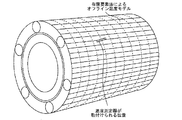
図2はこの発明の実施の形態1におけるモータシステムによるモータの内部温度の解析方法を説明するための図である。
Next, a method for analyzing the internal temperature of the
FIG. 2 is a diagram for explaining a method of analyzing the internal temperature of the motor by the motor system according to
オンライン温度モデルは、オフライン温度モデルの作成後に行われる。 The online temperature model is performed after the creation of the offline temperature model.
オフライン温度モデルに関し、モータ1の内部温度解析技術は、モータ1の設計の基本である。このため、モータ1の内部温度解析の手法は確立されている。例えば、モータ1の内部温度解析は、有限要素法を用いて行われる。有限要素法によれば、構造物は、有限な要素で区切られる。数値計算は、要素ごとに繰り返される。このため、複雑な構造物に対して解析的なアプローチが困難な場合でも、数値解が得られる。
Regarding the offline temperature model, the internal temperature analysis technology of the
図2に示すように、有限要素法における解析は、温度測定器が取り付けられる位置の温度に注目して行われる。この際、モータ1の動作状況に応じて変化するパラメータが外部入力として設定される。例えば、モータ1の周囲温度の測定値TambとR相の電圧の設定値VRとS相の電圧の設定値VSとT相の電圧の設定値VTとR相の電流の設定値IRとS相の電流の設定値ISとT相の電流の設定値ITと周波数の設定値fとが外部入力として設定される。
As shown in FIG. 2, the analysis in the finite element method is performed paying attention to the temperature at the position where the temperature measuring device is attached. At this time, a parameter that changes according to the operating state of the
オンライン温度モデルは、オフライン温度モデルに基づいて作成される。オンライン温度モデルは、モータ1の周囲温度の測定値TambとR相の電圧の設定値VRとS相の電圧の設定値VSとT相の電圧の設定値VTとR相の電流の設定値IRとS相の電流の設定値ISとT相の電流の設定値ITと周波数の設定値fとに対するR相の巻線の温度の推定値T2RとS相の巻線の温度の推定値T2SとT相の巻線の温度の推定値T2Tとの関係を示すモデルである。
The online temperature model is created based on the offline temperature model. The online temperature model includes a measured value T amb of the ambient temperature of the
例えば、オンライン温度モデルは、オフライン温度モデルの解析結果から一意的な関係式で示される。具体的には、R相の巻線の温度の推定値T2RとS相の巻線の温度の推定値T2SとT相の巻線の温度の推定値T2Tとは、次の(1)式から(3)式で示される。 For example, the online temperature model is represented by a unique relational expression from the analysis result of the offline temperature model. Specifically, the estimated value T2 R of the temperature of the R- phase winding, the estimated value T2 S of the temperature of the S-phase winding, and the estimated value T2 T of the temperature of the T-phase winding are the following (1 ) To (3).
![]()
![]()
![]()
![]()
![]()
![]()
例えば、オンライン温度モデルは、外部入力に対するオフライン温度モデルの解析結果を代表的にプロットしたグラフに対して隣接したプロットの間を補間した関係式で示される。 For example, the online temperature model is represented by a relational expression obtained by interpolating between adjacent plots with respect to a graph in which the analysis result of the offline temperature model with respect to the external input is typically plotted.
例えば、オンライン温度モデルは、外部入力に対するオフライン温度モデルの解析結果をテーブル化した関係で示される。 For example, the online temperature model is shown in a relation in which the analysis results of the offline temperature model with respect to the external input are tabulated.
次に、図3を用いて、モータ1の低負荷時における異常の感知方法を説明する。
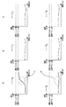
図3はこの発明の実施の形態1におけるモータシステムによるモータの低負荷時における異常の感知方法を説明するための図である。
Next, a method for detecting an abnormality when the
FIG. 3 is a diagram for explaining a method of detecting an abnormality at a low load of the motor by the motor system in the first embodiment of the present invention.
図3の(1)の上段は、R相の巻線の温度の測定値T1Rを示す。図3の(1)の下段は、R相の巻線の温度の推定値T2Rを示す。図3の(2)の上段は、S相の巻線の温度の測定値T1Sを示す。図3の(2)の下段は、S相の巻線の温度の推定値T2Sを示す。図3の(3)の上段は、T相の巻線の温度の測定値T1Tを示す。図3の(3)の下段は、T相の巻線の温度の推定値T2Tを示す。 The upper part of (1) in FIG. 3 shows a measured value T1 R of the temperature of the R-phase winding. Lower of (1) Figure 3 shows the estimated value T2 R of the temperature of the windings of the R-phase. The upper part of (2) in FIG. 3 shows a measured value T1 S of the temperature of the S-phase winding. Lower (2) Figure 3 shows the estimated value T2 S of the temperature of the windings of the S-phase. The upper part of (3) in FIG. 3 shows a measured value T1 T of the temperature of the T-phase winding. Lower (3) Figure 3 shows the estimated value T2 T of the temperature of the windings of the T-phase.
図3の(1)のA点において、R相の異常が発生した際、R相の巻線の温度の測定値T1Rは急激に大きくなる。この際、測定値T1Rは標準アラーム値よりも小さい。このため、通常アラームは出力されない。 When an R-phase abnormality occurs at point A in FIG. 3 (1), the measured value T1 R of the temperature of the R-phase winding increases rapidly. At this time, the measured value T1 R is smaller than the standard alarm value. For this reason, a normal alarm is not output.
しかしながら、図3の(1)のB点において、R相の巻線の温度の推定値T2Rは大きくならない。この際、R相の巻線の温度について測定値T1Rから推定値T2Rを差し引いた値にキャラブレーション項Tcal−Rを付加した値が温度推定アラーム値TALM−Rよりも大きくなる。このため、感知部10は、R相の異常を感知するアラームを出力する。
However, the point B (1) in FIG. 3, the estimated value T2 R of the temperature of the windings of the R-phase is not increased. In this case, greater than the character ablation section T cal-R by adding the value estimated temperature alarm value T ALM-R to a value obtained by subtracting the estimated value T2 R from the measured values T1 R for the temperature of the windings of the R-phase . For this reason, the
次に、図4を用いて、モータ1の経年変化の監視方法を説明する。
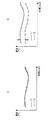
図4はこの発明の実施の形態1におけるモータシステムによるモータの経年変化の監視方法を説明するための図である。
Next, the monitoring method of the secular change of the
FIG. 4 is a diagram for explaining a monitoring method of a secular change of the motor by the motor system in the first embodiment of the present invention.
図4の(1)は、モータ1の稼働開始直後におけるモータ1の温度を示す。図4の(2)は、モータ1が長時間稼働した後におけるモータ1の温度を示す。
(1) in FIG. 4 shows the temperature of the
図4の(1)に示すように、モータ1の稼働開始直後において、各相の巻線の温度の測定値T1と推定値T2との差はほぼない。
As shown in (1) of FIG. 4, immediately after the start of operation of the
図4の(2)に示すように、モータ1が長時間稼働した後において、モータ1の負荷状況が同じであっても、各相の巻線の温度の測定値T1は、モータ1の経年変化の影響を受ける。これに対し、各相の巻線の温度の推定値T2は、モータ1の経年変化の影響を受けない。このため、各相の巻線の温度の測定値T1と推定値T2との差は、時間の経過とともに広がる。
As shown in (2) of FIG. 4, after the
保全装置8において、感知部10は、各相の巻線の温度の測定値T1と推定値T2との差を長期間監視する。感知部10は、各相の巻線の温度の測定値T1と推定値T2との差とに基づいてモータ11の予防保全を行う。例えば、感知部10は、各相の巻線の温度の測定値T1と推定値T2との差の時間的変化に基づいてモータ1の異常の前兆を感知する。
In the
以上で説明した実施の形態1によれば、モータ1の動作中において、モータ1の異常は、各相の巻線の温度の測定値T1と推定値T2との比較結果に基づいて感知される。このため、モータ1の異常を確実に感知することができる。
According to the first embodiment described above, during the operation of the
また、モータ1の異常の前兆は、各相の巻線の温度の測定値T1と推定値T2との差の時間的変化に基づいて行われる。このため、モータ1の異常の前兆を確実に感知することができる。
Moreover, the precursor of the abnormality of the
また、各相の巻線の温度の測定値T1と推定値T2とを比較すれば、オンライン温度モデルのキャリブレーションを容易に行うことができる。 Further, if the measured value T1 of the temperature of the winding of each phase is compared with the estimated value T2, the online temperature model can be easily calibrated.
次に、図5を用いて、保全装置8の例を説明する。
図5はこの発明の実施の形態1におけるモータシステムの保全装置のハードウェア構成図である。
Next, an example of the
FIG. 5 is a hardware configuration diagram of the motor system maintenance apparatus according to
保全装置8の各機能は、処理回路により実現される。例えば、処理回路は、少なくとも1つのプロセッサ11aと少なくとも1つのメモリ11bとを備える。例えば、処理回路は、少なくとも1つの専用のハードウェア12を備える。
Each function of the
処理回路が少なくとも1つのプロセッサ11aと少なくとも1つのメモリ11bとを備える場合、保全装置8の各機能は、ソフトウェア、ファームウェア、又はソフトウェアとファームウェアとの組み合わせにより実現される。ソフトウェアおよびファームウェアの少なくとも一方は、プログラムとして記述される。ソフトウェアおよびファームウェアの少なくとも一方は、少なくとも1つのメモリ11bに格納される。少なくとも1つのプロセッサ11aは、少なくとも1つのメモリ11bに記憶されたプログラムを読み出して実行することにより、保全装置8の各機能を実現する。少なくとも1つのプロセッサ11aは、CPU(Central Processing Unit)、中央処理装置、処理装置、演算装置、マイクロプロセッサ、マイクロコンピュータ、DSPともいう。例えば、少なくとも1つのメモリ11bは、RAM、ROM、フラッシュメモリ、EPROM、EEPROM等の、不揮発性又は揮発性の半導体メモリ、磁気ディスク、フレキシブルディスク、光ディスク、コンパクトディスク、ミニディスク、DVD等である。
When the processing circuit includes at least one
処理回路が少なくとも1つの専用のハードウェア12を備える場合、処理回路は、例えば、単一回路、複合回路、プログラム化したプロセッサ、並列プログラム化したプロセッサ、ASIC、FPGA、又はこれらを組み合わせたものである。例えば、保全装置8の各機能は、それぞれの処理回路で実現される。例えば、保全装置8の各機能は、まとめて処理回路で実現される。
If the processing circuit comprises at least one
保全装置8の各機能について、一部を専用のハードウェア12で実現し、他部をソフトウェア又はファームウェアで実現してもよい。例えば、推定部9の機能については専用のハードウェア12としての処理回路で実現し、感知部10の機能については少なくとも1つのプロセッサ11aが少なくとも1つのメモリ11bに格納されたプログラムを読み出して実行することによって実現してもよい。
About each function of the
このように、処理回路は、ハードウェア12、ソフトウェア、ファームウェア、又はこれらの組み合わせによって、保全装置8の各機能を実現する。
In this way, the processing circuit realizes each function of the
実施の形態2.
図6はこの発明の実施の形態2におけるモータシステムの構成図である。なお、実施の形態1と同一又は相当部分には、同一符号が付される。当該部分の説明は省略される。
6 is a block diagram of a motor system according to
図6において、実施の形態1の保全装置8は、各相の巻線の温度の測定値T1と推定値T2とを比較する。これに対し、実施の形態2の保全装置8は、各相の巻線の温度の測定値T1の勾配T1´と推定値T2の勾配T2´とを比較する。
In FIG. 6, the
具体的には、実施の形態2の保全装置8は、実施の形態1の保全装置8に第1勾配演算部13と第2勾配演算部14とを付加したものである。
Specifically, the
第1勾配演算部13は、各相の巻線における温度の測定値T1の離散データに後退差分を施すことにより勾配T1´を演算する。第2勾配演算部14は、各相の巻線における温度の推定値T2の離散データに後退差分を施すことにより勾配T2´を演算する。
The first
第1勾配演算部13と第2勾配演算部14とにおいて、サンプリング周期は、適宜設定される。当該サンプリング周期は、ドライブ装置7による制御周期と異なっていてもよい。当該サンプリング周期は、モータ1の温度監視に必要な周期であればよい。
In the first
実施の形態2において、感知部10は、各相の巻線の温度の測定値T1の勾配T1´と推定値T2の勾配T2´とを比較する。感知部10は、各相の巻線の温度の測定値T1の勾配T1´と推定値T2の勾配T2´との比較結果に基づいてモータ1の異常を感知する。
In the second embodiment, the
具体的には、感知部10は、R相の巻線の温度の測定値T1Rの勾配T1´Rと推定値T2Rの勾配T2´Rとの比較結果に基づいてR相の異常を感知する。例えば、感知部10は、S相の巻線の温度の測定値T1Sの勾配T1´Sと推定値T2Sの勾配T2´Sとの比較結果に基づいてS相の異常を感知する。例えば、感知部10は、T相の巻線の温度の測定値T1Tの勾配T1´Tと推定値T2Tの勾配T2´Tとの比較結果に基づいてS相の異常を感知する。
Specifically,
例えば、感知部10は、各相の巻線の温度の測定値T1の勾配T1´から推定値T2の勾配T2´を差し引いた値に予め設定されたキャラブレーション項T´calを付加した値と予め設定された温度推定アラーム値T´ALMとを比較する。
For example, the
具体的には、感知部10は、R相の巻線の温度について測定値T1Rの勾配T1´Rから推定値T2Rの勾配T2´Rを差し引いた値にキャラブレーション項T´cal−Rを付加した値と温度推定アラーム値T´ALM−Rとを比較する。感知部10は、S相の巻線の温度について測定値T1Sの勾配T1´Sから推定値T2Sの勾配T2´Sを差し引いた値にキャラブレーション項T´cal−Sを付加した値と温度推定アラーム値T´ALM−Sとを比較する。感知部10は、T相の巻線の温度について測定値T1Tの勾配T1´Tから推定値T2Tの勾配T2´Tを差し引いた値にキャラブレーション項T´cal−Tを付加した値と温度推定アラーム値T´ALM−Tとを比較する。
Specifically,
例えば、各相の巻線の温度の測定値T1の勾配T1´から推定値T2の勾配T2´を差し引いた値にキャラブレーション項T´calを付加した値が温度推定アラーム値T´ALMよりも大きい場合、感知部10は、モータ1の異常を感知するアラームを出力する。
For example, a value obtained by adding a character ablation claim T'cal gradient T1' to a value obtained by subtracting the gradient T2' estimate T2 measurements T1 of the temperature of the respective phase windings than the temperature estimated alarm value T'ALM Is larger, the
具体的には、R相の巻線の温度について測定値T1Rの勾配T1´Rから推定値T2Rの勾配T2´Rを差し引いた値にキャラブレーション項T´cal−Rを付加した値が温度推定アラーム値T´ALM−Rよりも大きい場合、感知部10は、R相の異常を感知するアラームを出力する。S相の巻線の温度について測定値T1Sの勾配T1´Sから推定値T2Sの勾配T2´Sを差し引いた値にキャラブレーション項T´cal−Sを付加した値が温度推定アラーム値T´ALM−Sよりも大きい場合、感知部10は、S相の異常を感知するアラームを出力する。T相の巻線の温度について測定値T1Tの勾配T1´Tから推定値T2Tの勾配T2´Tを差し引いた値にキャラブレーション項T´cal−Tを付加した値が温度推定アラーム値T´ALM−Tよりも大きい場合、感知部10は、T相の異常を感知するアラームを出力する。
Specifically, by adding a character ablation claim T'cal-R to a value obtained by subtracting the gradient T2 'R of the estimated value T2 R from the gradient T1' R measurements T1 R for the temperature of the windings of the R-phase value Is larger than the estimated temperature alarm value T ′ ALM-R , the
以上で説明した実施の形態2によれば、モータ1の異常は、各相の巻線の温度の測定値T1の勾配T1´と推定値T2の勾配T2´との比較結果に基づいて感知される。このため、モータ1の周囲の温度を測定することなく、モータ1の異常を確実に感知することができる。この際の絶対値温度に対する保護は従来方法を用いればよい。
According to the second embodiment described above, the abnormality of the
なお、実施の形態1および実施の形態2において、温度の測定箇所および推定箇所は、適宜設定してよい。モータ1において、異常感知の対象となる一部における温度の測定値と推定値とを比較すれば、より適切にモータ1の異常を感知することができる。
In the first embodiment and the second embodiment, the temperature measurement location and the estimation location may be set as appropriate. In the
また、実施の形態1および実施の形態2において、有限要素法による数値解は、計算誤差、繰り返しの演算の処理等の点で解析解よりも劣るもののオフラインでの解析においては問題とならない。 In the first and second embodiments, the numerical solution by the finite element method is inferior to the analytical solution in terms of calculation error, processing of repeated operations, etc., but does not cause a problem in the off-line analysis.
また、オンラインでの数値解析においては、処理速度が遅くなる。このため、オンラインで数値解析により温度の推定値を得ることができることは現実的でない。 In addition, the processing speed is slow in online numerical analysis. For this reason, it is not realistic that an estimated value of temperature can be obtained online by numerical analysis.
また、実施の形態1および実施の形態2の保全装置8を様々なモータに適用してもよい。例えば、保全装置8を同期機に適用してもよい。例えば、保全装置8を直流機に適用してもよい。例えば、保全装置8を小型のモータに適用してもよい。例えば、保全装置8を大型のモータに適用してもよい。
Moreover, you may apply the
1 モータ、 2 周囲温度測定器、 3 R相巻線温度測定器、 4 S相巻線温度測定器、 5 T相巻線温度測定器、 6 駆動制御システム、 7 ドライブ装置、 8 保全装置、 9 推定部、 10 感知部、 11a プロセッサ、 11b メモリ、 12 ハードウェア、 13 第1勾配演算部、 14 第2勾配演算部
DESCRIPTION OF
Claims (6)
前記モータの一部における温度の測定値の入力を温度測定器から受け付け、前記モータの一部における温度の推定値の入力を前記推定部から受け付け、前記モータの一部における温度の測定値と推定値との比較結果に基づいて前記モータの異常を感知する感知部と、
を備えたモータの保全装置。 An estimation unit for calculating an estimated value of a temperature in a part of the motor during operation of the motor by using a parameter that changes according to an operation state of the motor;
An input of a temperature measurement value at a part of the motor is received from a temperature measuring device, an input of an estimated temperature value at a part of the motor is received from the estimation unit, and a temperature measurement value and an estimation at a part of the motor are received. A sensing unit for sensing an abnormality of the motor based on a comparison result with a value;
Motor maintenance device with
前記モータの一部における温度の測定値の入力を温度測定器から受け付け、前記モータの動作状況に応じて変化するパラメータを入力として前記モータの動作中に前記モータの一部における温度の推定値を演算し、前記モータの一部における温度の測定値と推定値との比較結果に基づいて前記モータの異常を感知する保全装置と、
を備えたモータシステム。 A motor that changes the temperature according to the operating conditions;
An input of a temperature measurement value in a part of the motor is received from a temperature measuring device, and an estimated value of a temperature in the part of the motor is obtained during operation of the motor by using a parameter that changes according to the operation state of the motor as an input. A maintenance device that calculates and senses an abnormality of the motor based on a comparison result between a measured value and an estimated value of temperature in a part of the motor;
Motor system equipped with.
Priority Applications (1)
| Application Number | Priority Date | Filing Date | Title |
|---|---|---|---|
| JP2016000080A JP2017123701A (en) | 2016-01-04 | 2016-01-04 | Motor maintenance device and motor system |
Applications Claiming Priority (1)
| Application Number | Priority Date | Filing Date | Title |
|---|---|---|---|
| JP2016000080A JP2017123701A (en) | 2016-01-04 | 2016-01-04 | Motor maintenance device and motor system |
Publications (1)
| Publication Number | Publication Date |
|---|---|
| JP2017123701A true JP2017123701A (en) | 2017-07-13 |
Family
ID=59306711
Family Applications (1)
| Application Number | Title | Priority Date | Filing Date |
|---|---|---|---|
| JP2016000080A Pending JP2017123701A (en) | 2016-01-04 | 2016-01-04 | Motor maintenance device and motor system |
Country Status (1)
| Country | Link |
|---|---|
| JP (1) | JP2017123701A (en) |
Cited By (2)
| Publication number | Priority date | Publication date | Assignee | Title |
|---|---|---|---|---|
| JPWO2024034030A1 (en) * | 2022-08-09 | 2024-02-15 | ||
| WO2024034027A1 (en) * | 2022-08-09 | 2024-02-15 | ファナック株式会社 | Monitoring device for electric motor |
Citations (6)
| Publication number | Priority date | Publication date | Assignee | Title |
|---|---|---|---|---|
| JPS61173692A (en) * | 1985-01-25 | 1986-08-05 | Toshiba Corp | Malfunction monitor |
| JPH099684A (en) * | 1995-06-19 | 1997-01-10 | Hitachi Ltd | Inverter drive motor thermal protection device |
| JP2007315994A (en) * | 2006-05-29 | 2007-12-06 | Toyota Motor Corp | Method and apparatus for detecting temperature change of rotating electrical machine |
| JP2010268644A (en) * | 2009-05-18 | 2010-11-25 | Nissan Motor Co Ltd | Motor temperature abnormality detection device |
| JP2011085477A (en) * | 2009-10-15 | 2011-04-28 | Toyota Motor Corp | Failure decision apparatus of temperature sensor, driving apparatus with the same, and failure decision method of temperature sensor |
| US20120330483A1 (en) * | 2011-06-27 | 2012-12-27 | Gm Global Technology Operations Llc. | Rotor temperature estimation for an electric vehicle |
-
2016
- 2016-01-04 JP JP2016000080A patent/JP2017123701A/en active Pending
Patent Citations (6)
| Publication number | Priority date | Publication date | Assignee | Title |
|---|---|---|---|---|
| JPS61173692A (en) * | 1985-01-25 | 1986-08-05 | Toshiba Corp | Malfunction monitor |
| JPH099684A (en) * | 1995-06-19 | 1997-01-10 | Hitachi Ltd | Inverter drive motor thermal protection device |
| JP2007315994A (en) * | 2006-05-29 | 2007-12-06 | Toyota Motor Corp | Method and apparatus for detecting temperature change of rotating electrical machine |
| JP2010268644A (en) * | 2009-05-18 | 2010-11-25 | Nissan Motor Co Ltd | Motor temperature abnormality detection device |
| JP2011085477A (en) * | 2009-10-15 | 2011-04-28 | Toyota Motor Corp | Failure decision apparatus of temperature sensor, driving apparatus with the same, and failure decision method of temperature sensor |
| US20120330483A1 (en) * | 2011-06-27 | 2012-12-27 | Gm Global Technology Operations Llc. | Rotor temperature estimation for an electric vehicle |
Cited By (5)
| Publication number | Priority date | Publication date | Assignee | Title |
|---|---|---|---|---|
| JPWO2024034030A1 (en) * | 2022-08-09 | 2024-02-15 | ||
| WO2024034030A1 (en) * | 2022-08-09 | 2024-02-15 | ファナック株式会社 | Electric motor monitoring device |
| WO2024034027A1 (en) * | 2022-08-09 | 2024-02-15 | ファナック株式会社 | Monitoring device for electric motor |
| JPWO2024034027A1 (en) * | 2022-08-09 | 2024-02-15 | ||
| JP7846233B2 (en) | 2022-08-09 | 2026-04-14 | ファナック株式会社 | Motor monitoring device |
Similar Documents
| Publication | Publication Date | Title |
|---|---|---|
| US10960922B2 (en) | Fault tolerant field oriented control for electric power steering | |
| JP5397023B2 (en) | AC motor control device | |
| JP5607698B2 (en) | Temperature estimation device for estimating the temperature of an electric motor | |
| JP5611466B2 (en) | Rotating machine control device | |
| JPWO2010100998A1 (en) | Insulation deterioration detector | |
| EP3054307A1 (en) | Stator fault detection and diagnosis | |
| CN110658453B (en) | Asynchronous motor work abnormity detection method and device | |
| US20190173413A1 (en) | Motor module, motor controller, temperature inferring device, and temperature inference method | |
| JP6238928B2 (en) | Diagnostic equipment for electric motors | |
| US10717463B2 (en) | Feedforward control of permanent magnet synchronous motor drive under current sensing failure | |
| JPH1084688A (en) | Apparatus and method for detecting abnormal state of motor | |
| US8368420B2 (en) | Method of error detection when controlling a rotating-field motor | |
| US9146166B2 (en) | Method and apparatus for determining an electrical torque of an electrical machine | |
| KR20150080063A (en) | Device and method of trouble diagnosis for synchronous generator using an extended Kalman filter | |
| CN109217739B (en) | Method for detecting load difference | |
| JP2017123701A (en) | Motor maintenance device and motor system | |
| US12196620B2 (en) | Motor temperature estimation system, motor temperature estimation method, and motor temperature estimation program | |
| NL2022591B1 (en) | Resistance determination in an electric motor assembly | |
| JP2007315994A (en) | Method and apparatus for detecting temperature change of rotating electrical machine | |
| US9397554B2 (en) | Motor drive device having function of estimating dead time in output stage | |
| JP2012225692A (en) | Abnormal contact detecting device | |
| JP2023004456A (en) | Electric motor control apparatus | |
| JP6588261B2 (en) | Insulation monitoring device and inverter device | |
| JP6508021B2 (en) | Motor temperature estimation device | |
| JP6359691B2 (en) | Power converter and control method of power converter |
Legal Events
| Date | Code | Title | Description |
|---|---|---|---|
| A621 | Written request for application examination |
Free format text: JAPANESE INTERMEDIATE CODE: A621 Effective date: 20180202 |
|
| A131 | Notification of reasons for refusal |
Free format text: JAPANESE INTERMEDIATE CODE: A131 Effective date: 20181127 |
|
| A977 | Report on retrieval |
Free format text: JAPANESE INTERMEDIATE CODE: A971007 Effective date: 20181130 |
|
| A521 | Request for written amendment filed |
Free format text: JAPANESE INTERMEDIATE CODE: A523 Effective date: 20190125 |
|
| A02 | Decision of refusal |
Free format text: JAPANESE INTERMEDIATE CODE: A02 Effective date: 20190205 |