JP2017122414A - Cryopump - Google Patents
Cryopump Download PDFInfo
- Publication number
- JP2017122414A JP2017122414A JP2016002490A JP2016002490A JP2017122414A JP 2017122414 A JP2017122414 A JP 2017122414A JP 2016002490 A JP2016002490 A JP 2016002490A JP 2016002490 A JP2016002490 A JP 2016002490A JP 2017122414 A JP2017122414 A JP 2017122414A
- Authority
- JP
- Japan
- Prior art keywords
- shield
- cryopanel
- cryopump
- opening
- cooling stage
- Prior art date
- Legal status (The legal status is an assumption and is not a legal conclusion. Google has not performed a legal analysis and makes no representation as to the accuracy of the status listed.)
- Granted
Links
- 238000001816 cooling Methods 0.000 claims abstract description 84
- 230000005855 radiation Effects 0.000 claims abstract description 49
- 238000005057 refrigeration Methods 0.000 abstract 1
- 239000007789 gas Substances 0.000 description 50
- 238000001179 sorption measurement Methods 0.000 description 10
- UFHFLCQGNIYNRP-UHFFFAOYSA-N Hydrogen Chemical compound [H][H] UFHFLCQGNIYNRP-UHFFFAOYSA-N 0.000 description 5
- 238000009833 condensation Methods 0.000 description 5
- 230000005494 condensation Effects 0.000 description 5
- 239000001257 hydrogen Substances 0.000 description 5
- 229910052739 hydrogen Inorganic materials 0.000 description 5
- 238000000034 method Methods 0.000 description 5
- 230000002093 peripheral effect Effects 0.000 description 5
- 239000003463 adsorbent Substances 0.000 description 3
- XKRFYHLGVUSROY-UHFFFAOYSA-N Argon Chemical compound [Ar] XKRFYHLGVUSROY-UHFFFAOYSA-N 0.000 description 2
- OKTJSMMVPCPJKN-UHFFFAOYSA-N Carbon Chemical compound [C] OKTJSMMVPCPJKN-UHFFFAOYSA-N 0.000 description 2
- 239000000470 constituent Substances 0.000 description 2
- 230000000694 effects Effects 0.000 description 2
- 230000014509 gene expression Effects 0.000 description 2
- 238000005468 ion implantation Methods 0.000 description 2
- 238000004519 manufacturing process Methods 0.000 description 2
- 238000012986 modification Methods 0.000 description 2
- 230000004048 modification Effects 0.000 description 2
- 229910052786 argon Inorganic materials 0.000 description 1
- 230000004323 axial length Effects 0.000 description 1
- 235000012489 doughnuts Nutrition 0.000 description 1
- -1 for example Substances 0.000 description 1
- 239000001307 helium Substances 0.000 description 1
- 229910052734 helium Inorganic materials 0.000 description 1
- SWQJXJOGLNCZEY-UHFFFAOYSA-N helium atom Chemical compound [He] SWQJXJOGLNCZEY-UHFFFAOYSA-N 0.000 description 1
- 239000002184 metal Substances 0.000 description 1
- 239000004570 mortar (masonry) Substances 0.000 description 1
- 238000002310 reflectometry Methods 0.000 description 1
- 230000008929 regeneration Effects 0.000 description 1
- 238000011069 regeneration method Methods 0.000 description 1
- 239000004065 semiconductor Substances 0.000 description 1
- 238000004544 sputter deposition Methods 0.000 description 1
- 239000000758 substrate Substances 0.000 description 1
- 238000007740 vapor deposition Methods 0.000 description 1
- XLYOFNOQVPJJNP-UHFFFAOYSA-N water Chemical compound O XLYOFNOQVPJJNP-UHFFFAOYSA-N 0.000 description 1
Images

Classifications
-
- F—MECHANICAL ENGINEERING; LIGHTING; HEATING; WEAPONS; BLASTING
- F04—POSITIVE - DISPLACEMENT MACHINES FOR LIQUIDS; PUMPS FOR LIQUIDS OR ELASTIC FLUIDS
- F04B—POSITIVE-DISPLACEMENT MACHINES FOR LIQUIDS; PUMPS
- F04B37/00—Pumps having pertinent characteristics not provided for in, or of interest apart from, groups F04B25/00 - F04B35/00
- F04B37/06—Pumps having pertinent characteristics not provided for in, or of interest apart from, groups F04B25/00 - F04B35/00 for evacuating by thermal means
- F04B37/08—Pumps having pertinent characteristics not provided for in, or of interest apart from, groups F04B25/00 - F04B35/00 for evacuating by thermal means by condensing or freezing, e.g. cryogenic pumps
-
- B—PERFORMING OPERATIONS; TRANSPORTING
- B01—PHYSICAL OR CHEMICAL PROCESSES OR APPARATUS IN GENERAL
- B01D—SEPARATION
- B01D8/00—Cold traps; Cold baffles
-
- F—MECHANICAL ENGINEERING; LIGHTING; HEATING; WEAPONS; BLASTING
- F04—POSITIVE - DISPLACEMENT MACHINES FOR LIQUIDS; PUMPS FOR LIQUIDS OR ELASTIC FLUIDS
- F04B—POSITIVE-DISPLACEMENT MACHINES FOR LIQUIDS; PUMPS
- F04B15/00—Pumps adapted to handle specific fluids, e.g. by selection of specific materials for pumps or pump parts
-
- F—MECHANICAL ENGINEERING; LIGHTING; HEATING; WEAPONS; BLASTING
- F04—POSITIVE - DISPLACEMENT MACHINES FOR LIQUIDS; PUMPS FOR LIQUIDS OR ELASTIC FLUIDS
- F04B—POSITIVE-DISPLACEMENT MACHINES FOR LIQUIDS; PUMPS
- F04B53/00—Component parts, details or accessories not provided for in, or of interest apart from, groups F04B1/00 - F04B23/00 or F04B39/00 - F04B47/00
Abstract
Description
本発明は、クライオポンプに関する。 The present invention relates to a cryopump.
クライオポンプは、極低温に冷却されたクライオパネルに気体分子を凝縮または吸着により捕捉して排気する真空ポンプである。クライオポンプは半導体回路製造プロセス等に要求される清浄な真空環境を実現するために一般に利用される。クライオポンプのアプリケーションの1つに、例えばイオン注入工程のように、排気すべき気体の大半を例えば水素等の非凝縮性気体が占める場合がある。非凝縮性気体は極低温に冷却された吸着領域に吸着させることによって初めて排気することができる。 The cryopump is a vacuum pump that traps and exhausts gas molecules by condensation or adsorption onto a cryopanel cooled to a very low temperature. The cryopump is generally used to realize a clean vacuum environment required for a semiconductor circuit manufacturing process or the like. One application of a cryopump is when a non-condensable gas such as hydrogen occupies most of the gas to be evacuated, such as in an ion implantation process. A non-condensable gas can be exhausted only by adsorbing it in an adsorption region cooled to a very low temperature.
本発明のある態様の例示的な目的のひとつは、クライオポンプの非凝縮性気体の排気性能を向上することにある。 One exemplary object of an aspect of the present invention is to improve the exhaust performance of a non-condensable gas of a cryopump.
本発明のある態様によると、クライオポンプは、第1冷却温度に冷却される第1冷却ステージと、前記第1冷却温度より低い第2冷却温度に冷却される第2冷却ステージと、前記第2冷却ステージを前記第1冷却ステージに構造的に支持する冷凍機構造部と、を備える冷凍機と、前記第2冷却ステージに熱的に結合されているクライオパネルユニットと、シールド主開口、シールド側部開口、およびシールド底部開口を有し、前記第2冷却ステージおよび前記クライオパネルユニットを包囲する放射シールドであって、前記冷凍機構造部が前記シールド側部開口に挿通された状態で前記第1冷却ステージに熱的に結合されている放射シールドと、前記シールド底部開口に面するハウジング底部を有し、前記放射シールドを包囲するクライオポンプハウジングと、を備える。前記シールド底部開口の寸法は、前記クライオパネルユニットから前記ハウジング底部への距離より大きい。 According to an aspect of the present invention, the cryopump includes a first cooling stage that is cooled to a first cooling temperature, a second cooling stage that is cooled to a second cooling temperature lower than the first cooling temperature, and the second cooling stage. A refrigerator that structurally supports a cooling stage on the first cooling stage, a cryopanel unit that is thermally coupled to the second cooling stage, a shield main opening, and a shield side A radiation shield that surrounds the second cooling stage and the cryopanel unit, wherein the refrigerator structure portion is inserted through the shield side portion opening. A cryopo which has a radiation shield thermally coupled to the cooling stage and a housing bottom facing the shield bottom opening and surrounds the radiation shield It includes a flop housing. The dimension of the shield bottom opening is larger than the distance from the cryopanel unit to the housing bottom.
なお、以上の構成要素の任意の組み合わせや本発明の構成要素や表現を、方法、装置、システムなどの間で相互に置換したものもまた、本発明の態様として有効である。 Note that any combination of the above-described constituent elements and the constituent elements and expressions of the present invention replaced with each other among methods, apparatuses, systems, and the like are also effective as an aspect of the present invention.
本発明によれば、クライオポンプの非凝縮性気体の排気性能が向上される。 According to the present invention, the exhaust performance of the non-condensable gas of the cryopump is improved.
以下、図面を参照しながら、本発明を実施するための形態について詳細に説明する。なお、説明において同一の要素には同一の符号を付し、重複する説明を適宜省略する。また、以下に述べる構成は例示であり、本発明の範囲を何ら限定するものではない。 Hereinafter, embodiments for carrying out the present invention will be described in detail with reference to the drawings. In the description, the same elements are denoted by the same reference numerals, and repeated descriptions are omitted as appropriate. Moreover, the structure described below is an illustration and does not limit the scope of the present invention at all.
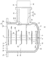
図1は、本発明の第1実施形態に係るクライオポンプ10を概略的に示す。クライオポンプ10は、例えばイオン注入装置、スパッタリング装置、蒸着装置、またはその他の真空プロセス装置の真空チャンバに取り付けられて、真空チャンバ内部の真空度を所望の真空プロセスに要求されるレベルまで高めるために使用される。クライオポンプ10は、排気されるべき気体を真空チャンバから受け入れるための吸気口12を有する。吸気口12を通じて気体がクライオポンプ10の内部空間14に進入する。
FIG. 1 schematically shows a
なお以下では、クライオポンプ10の構成要素の位置関係をわかりやすく表すために、「軸方向」、「径方向」との用語を使用することがある。軸方向は吸気口12を通る方向(図1において中心軸Aに沿う方向)を表し、径方向は吸気口12に沿う方向(中心軸Aに垂直な方向)を表す。便宜上、軸方向に関して吸気口12に相対的に近いことを「上」、相対的に遠いことを「下」と呼ぶことがある。つまり、クライオポンプ10の底部から相対的に遠いことを「上」、相対的に近いことを「下」と呼ぶことがある。径方向に関しては、吸気口12の中心(図1において中心軸A)に近いことを「内」、吸気口12の周縁に近いことを「外」と呼ぶことがある。なお、こうした表現はクライオポンプ10が真空チャンバに取り付けられたときの配置とは関係しない。例えば、クライオポンプ10は鉛直方向に吸気口12を下向きにして真空チャンバに取り付けられてもよい。
In the following description, the terms “axial direction” and “radial direction” are sometimes used to express the positional relationship of the components of the
また、軸方向を囲む方向を「周方向」と呼ぶことがある。周方向は、吸気口12に沿う第2の方向であり、径方向に直交する接線方向である。
Further, the direction surrounding the axial direction may be referred to as “circumferential direction”. The circumferential direction is a second direction along the
クライオポンプ10は、冷凍機16、第1クライオパネルユニット18、第2クライオパネルユニット20、及び、クライオポンプハウジング70を備える。
The
冷凍機16は、例えばギフォード・マクマホン式冷凍機(いわゆるGM冷凍機)などの極低温冷凍機である。冷凍機16は、二段式の冷凍機である。そのため、冷凍機16は、第1冷却ステージ22及び第2冷却ステージ24を備える。冷凍機16は、第1冷却ステージ22を第1冷却温度に冷却し、第2冷却ステージ24を第2冷却温度に冷却するよう構成されている。第2冷却温度は第1冷却温度よりも低温である。例えば、第1冷却ステージ22は65K〜120K程度、好ましくは80K〜100Kに冷却され、第2冷却ステージ24は10K〜20K程度に冷却される。
The
また、冷凍機16は、第2冷却ステージ24を第1冷却ステージ22に構造的に支持するとともに第1冷却ステージ22を冷凍機16の室温部26に構造的に支持する冷凍機構造部21を備える。そのため冷凍機構造部21は、径方向に沿って同軸に延在する第1シリンダ23及び第2シリンダ25を備える。第1シリンダ23は、冷凍機16の室温部26を第1冷却ステージ22に接続する。第2シリンダ25は、第1冷却ステージ22を第2冷却ステージ24に接続する。室温部26、第1シリンダ23、第1冷却ステージ22、第2シリンダ25、及び第2冷却ステージ24は、この順に直線状に一列に並ぶ。
The
第1シリンダ23及び第2シリンダ25それぞれの内部には第1ディスプレーサ及び第2ディスプレーサ(図示せず)が往復動可能に配設されている。第1ディスプレーサ及び第2ディスプレーサにはそれぞれ第1蓄冷器及び第2蓄冷器(図示せず)が組み込まれている。また、室温部26は、第1ディスプレーサ及び第2ディスプレーサを往復動させるための駆動機構(図示せず)を有する。駆動機構は、冷凍機16の内部への作動気体(例えばヘリウム)の供給と排出を周期的に繰り返すよう作動気体の流路を切り替える流路切替機構を含む。
Inside each of the
冷凍機16は、作動気体の圧縮機(図示せず)に接続されている。冷凍機16は、圧縮機により加圧された作動気体を内部で膨張させて第1冷却ステージ22及び第2冷却ステージ24を冷却する。膨張した作動気体は圧縮機に回収され再び加圧される。冷凍機16は、作動気体の給排とこれに同期した第1ディスプレーサ及び第2ディスプレーサの往復動とを含む熱サイクルを繰り返すことによって寒冷を発生させる。
The
図示されるクライオポンプ10は、いわゆる横型のクライオポンプである。横型のクライオポンプとは一般に、冷凍機16がクライオポンプ10の中心軸Aに交差する(通常は直交する)よう配設されているクライオポンプである。
The illustrated
第1クライオパネルユニット18は、放射シールド30と入口クライオパネル32とを備え、第2クライオパネルユニット20を包囲する。第1クライオパネルユニット18は、クライオポンプ10の外部またはクライオポンプハウジング70からの輻射熱から第2クライオパネルユニット20を保護するための極低温表面を提供する。第1クライオパネルユニット18は第1冷却ステージ22に熱的に結合されている。よって第1クライオパネルユニット18は第1冷却温度に冷却される。第1クライオパネルユニット18は第2クライオパネルユニット20との間に隙間を有しており、第1クライオパネルユニット18は第2クライオパネルユニット20と接触していない。第1クライオパネルユニット18はクライオポンプハウジング70とも接触していない。
The
放射シールド30は、クライオポンプハウジング70の輻射熱から第2クライオパネルユニット20を保護するために設けられている。放射シールド30は、クライオポンプハウジング70と第2クライオパネルユニット20との間にあり、第2クライオパネルユニット20を囲む。放射シールド30は、クライオポンプ10の外部から内部空間14に気体を受け入れるためのシールド主開口34を有する。シールド主開口34は、吸気口12に位置する。
The
放射シールド30は、シールド主開口34を定めるシールド前端36と、シールド主開口34と反対側に位置するシールド底部38と、シールド前端36をシールド底部38に接続するシールド側部40と、を備える。シールド側部40は、軸方向にシールド前端36からシールド主開口34と反対側へと延在し、周方向に第2冷却ステージ24を包囲するよう延在する。
The
シールド底部38は、シールド底部開口42を有する。シールド底部開口42は、例えば、シールド底部38の中心に形成された円形開口であり、開口径(開口部直径)Dを有する。
The shield bottom 38 has a
シールド側部40は、冷凍機構造部21が挿入されるシールド側部開口44を有する。シールド側部開口44を通じて放射シールド30の外から第2冷却ステージ24及び第2シリンダ25が放射シールド30の中に挿入される。シールド側部開口44は、シールド側部40に形成された取付穴であり、例えば円形である。第1冷却ステージ22は放射シールド30の外に配置されている。
The
シールド側部40は、冷凍機16の取付座46を備える。取付座46は、第1冷却ステージ22を放射シールド30に取り付けるための平坦部分であり、放射シールド30の外から見てわずかに窪んでいる。取付座46は、シールド側部開口44の外周を形成する。第1冷却ステージ22が取付座46に取り付けられることによって、放射シールド30が第1冷却ステージ22に熱的に結合されている。
The
このように放射シールド30を第1冷却ステージ22に直接取り付けることに代えて、ある実施形態においては、放射シールド30は、追加の伝熱部材を介して第1冷却ステージ22に熱的に結合されていてもよい。伝熱部材は、例えば、両端にフランジを有する中空の短筒であってもよい。伝熱部材は、その一端のフランジにより取付座46に固定され、他端のフランジにより第1冷却ステージ22に固定されてもよい。伝熱部材は、冷凍機構造部21を囲んで第1冷却ステージ22から放射シールド30に延在してもよい。シールド側部40は、こうした伝熱部材を含んでもよい。
Instead of attaching the
図示される実施形態においては、放射シールド30は一体の筒状に構成されている。これに代えて、放射シールド30は、複数のパーツにより全体として筒状の形状をなすように構成されていてもよい。これら複数のパーツは互いに間隙を有して配設されていてもよい。例えば、放射シールド30は軸方向に2つの部分に分割されていてもよい。この場合、放射シールド30の上部は、両端が開放された筒であり、シールド前端36とシールド側部40の第1部分とを備える。放射シールド30の下部も両端が開放された筒であり、シールド側部40の第2部分とシールド底部38とを備える。シールド側部40の第1部分と第2部分との間には周方向に延びるスリットが形成されている。このスリットが、シールド側部開口44の少なくとも一部を形成してもよい。あるいは、シールド側部開口44は、その上半分がシールド側部40の第1部分に形成され、下半分がシールド側部40の第2部分に形成されてもよい。
In the illustrated embodiment, the
放射シールド30は、第2クライオパネルユニット20を囲むガス受入空間50を、吸気口12とシールド底部38との間に形成する。ガス受入空間50は、クライオポンプ10の内部空間14の一部であり、第2クライオパネルユニット20に径方向に隣接する領域である。
The
入口クライオパネル32は、クライオポンプ10の外部の熱源(例えば、クライオポンプ10が取り付けられる真空チャンバ内の熱源)からの輻射熱から第2クライオパネルユニット20を保護するために、吸気口12(またはシールド主開口34、以下同様)に設けられている。また、入口クライオパネル32の冷却温度で凝縮する気体(例えば水分)がその表面に捕捉される。
The
入口クライオパネル32は、吸気口12において第2クライオパネルユニット20に対応する場所に配置されている。入口クライオパネル32は、吸気口12の開口面積の中心部分を占有し、放射シールド30との間に環状の開放領域51を形成する。開放領域51は、吸気口12においてガス受入空間50に対応する場所にある。ガス受入空間50が第2クライオパネルユニット20を囲むように内部空間14の外周部にあるので、開放領域51は、吸気口12の外周部に位置する。開放領域51はガス受入空間50の入口であり、クライオポンプ10は、開放領域51を通じてガス受入空間50にガスを受け入れる。
The
入口クライオパネル32は取付部材(図示せず)を介してシールド前端36に取り付けられる。こうして入口クライオパネル32は放射シールド30に固定され、放射シールド30に熱的に接続されている。入口クライオパネル32は第2クライオパネルユニット20に近接しているが、接触はしていない。
The
入口クライオパネル32は、吸気口12に配設される平面的な構造を備える。入口クライオパネル32は例えば、同心円状または格子状に形成されたルーバーまたはシェブロンを備えてもよいし、平板(例えば円板)のプレートを備えてもよい。入口クライオパネル32は、吸気口12の全体を横断するように配設されていてもよい。その場合、開放領域51は、プレートの一部を欠落させ、または、ルーバーまたはシェブロンの一部の羽板を欠落させることによって形成されていてもよい。
The
第2クライオパネルユニット20は、クライオポンプ10の内部空間14の中心部に設けられている。第2クライオパネルユニット20は、複数のクライオパネル60と、パネル取付部材62と、を備える。パネル取付部材62は、第2冷却ステージ24から軸方向に上方および下方に向けて延びている。第2クライオパネルユニット20は、パネル取付部材62を介して第2冷却ステージ24に取り付けられている。このようにして、第2クライオパネルユニット20は、第2冷却ステージ24に熱的に接続されている。よって、第2クライオパネルユニット20は第2冷却温度に冷却される。
The
第2クライオパネルユニット20においては、少なくとも一部の表面に吸着領域64が形成されている。吸着領域64は非凝縮性気体(例えば水素)を吸着により捕捉するために設けられている。吸着領域64は、吸気口12から見えないように、上方に隣接するクライオパネル60の陰となる場所に形成されている。つまり、吸着領域64は各クライオパネル60の上面中心部と下面全域に形成されている。ただし、トップクライオパネル60aの上面に吸着領域64は設けられていない。吸着領域64は例えば吸着剤(例えば活性炭)をクライオパネル表面に接着することにより形成される。
In the
また、第2クライオパネルユニット20の少なくとも一部の表面には凝縮性気体を凝縮により捕捉するための凝縮領域が形成されている。凝縮領域は例えば、クライオパネル表面上で吸着剤の欠落した区域であり、クライオパネル基材表面例えば金属面が露出されている。
In addition, a condensation region for capturing condensable gas by condensation is formed on at least a part of the surface of the
複数のクライオパネル60が、シールド主開口34からシールド底部38へと向かう方向に沿って(即ち中心軸Aに沿って)パネル取付部材62上に配列されている。複数のクライオパネル60はそれぞれ中心軸Aに垂直に延在する平板(例えば円板)であり、互いに平行にパネル取付部材62に取り付けられている。説明の便宜上、複数のクライオパネル60のうち最も吸気口12に近いものをトップクライオパネル60aと呼び、複数のクライオパネル60のうち最もシールド底部38に近いものをボトムクライオパネル60bと呼ぶことがある。
A plurality of
第2クライオパネルユニット20は、吸気口12とシールド底部38との間で軸方向に沿って細長く延びている。第2クライオパネルユニット20の軸方向の垂直投影の外形寸法よりも、軸方向における第2クライオパネルユニット20の上端から下端までの距離は長い。例えば、クライオパネル60の幅または直径よりも、トップクライオパネル60aとボトムクライオパネル60bとの間隔が大きい。
The
複数のクライオパネル60は図示されるようにそれぞれ同一形状を有してもよいし、異なる形状(例えば異なる径)を有してもよい。複数のクライオパネル60のうちあるクライオパネル60は、その上方に隣接するクライオパネル60と同一形状を有するか、または大型であってもよい。その結果、ボトムクライオパネル60bはトップクライオパネル60aより大きくてもよい。ボトムクライオパネル60bの面積は、トップクライオパネル60aの面積の約1.5倍〜約5倍であってもよい。
The plurality of
また、複数のクライオパネル60の間隔は図示されるように一定であってもよいし、互いに異なっていてもよい。
Further, the intervals between the plurality of
クライオポンプハウジング70は、第1クライオパネルユニット18、第2クライオパネルユニット20、及び冷凍機16を収容するクライオポンプ10の筐体であり、内部空間14の真空気密を保持するよう構成されている真空容器である。クライオポンプハウジング70は、第1クライオパネルユニット18及び冷凍機構造部21を非接触に包含する。クライオポンプハウジング70は、冷凍機16の室温部26に取り付けられている。
The
クライオポンプハウジング70の前端によって、吸気口12が画定されている。クライオポンプハウジング70は、その前端から径方向外側に向けて延びている吸気口フランジ72を備える。吸気口フランジ72は、クライオポンプハウジング70の全周にわたって設けられている。クライオポンプ10は、吸気口フランジ72を用いて真空排気対象の真空チャンバに取り付けられる。
The
クライオポンプハウジング70は、シールド底部開口42に面するハウジング底部74を有する。ハウジング底部74はドーム状に湾曲している。ハウジング底部74の内面は、ごく小さい輻射率を有してもよい。例えば、ハウジング底部74の内面は、輻射エネルギー量が完全黒体の10%以下となる表面であってもよい。言い換えれば、ハウジング底部74の内面は、反射面であってもよい。このように輻射率を小さくする(反射率を大きくする)ために、ハウジング底部74の内面は電解研磨処理が施されていてもよい。
The
ある典型的なクライオポンプのシールド底部には再生時に融解物の流出用の小穴が設けられていることがある。そうした小穴はシールド内部のクライオパネルをハウジングにさらさないように極小の開口寸法を有する。これと異なり、シールド底部開口42は相当に大きく開放されている。第2クライオパネルユニット20に近いシールド底部の領域が取り除かれてシールド底部開口42が形成されている。
The bottom of the shield of a typical cryopump may have a small hole for melt outflow during regeneration. Such a small hole has a very small opening size so that the cryopanel inside the shield is not exposed to the housing. In contrast to this, the shield bottom opening 42 is considerably open. The area of the shield bottom near the
シールド底部開口42の直径Dは、第2クライオパネルユニット20(すなわちボトムクライオパネル60b)からハウジング底部74への距離Bより大きい。例えば、シールド底部開口42の直径Dは、距離Bの少なくとも2倍、3倍、5倍、または10倍より大きくてもよい。このようにして、シールド底部38には大きな開口部が形成されている。言うまでもないが、直径Dは、シールド主開口34の直径より小さい。直径Dは、例えば、シールド主開口34の直径の90%、75%、または50%より小さくてもよい。
The diameter D of the shield bottom opening 42 is larger than the distance B from the second cryopanel unit 20 (that is, the
また、シールド底部開口42の直径Dは、ボトムクライオパネル60bの直径Cに相当する。シールド底部開口42の直径Dは、ボトムクライオパネル60bの直径Cの80%から120%または90%から110%の範囲にあってもよい。このようにして、吸気口12から見たときボトムクライオパネル60bがハウジング底部74の大半または全域を覆っている。図示されるように、平板状のボトムクライオパネル60bの外周部とシールド底部38との干渉を確実に避けるように、シールド底部開口42の直径Dは、ボトムクライオパネル60bの直径Cより大きくてもよい。
Further, the diameter D of the shield bottom opening 42 corresponds to the diameter C of the
上記の構成のクライオポンプ10の動作を以下に説明する。クライオポンプ10の作動に際しては、まずその作動前に他の適当な粗引きポンプで真空チャンバ内部を1Pa程度にまで粗引きする。その後、クライオポンプ10を作動させる。冷凍機16の駆動により第1冷却ステージ22及び第2冷却ステージ24がそれぞれ第1冷却温度及び第2冷却温度に冷却される。よって、これらに熱的に結合されている第1クライオパネルユニット18、第2クライオパネルユニット20もそれぞれ第1冷却温度及び第2冷却温度に冷却される。
The operation of the
入口クライオパネル32は、真空チャンバからクライオポンプ10に向かって飛来する気体を冷却する。入口クライオパネル32の表面には、第1冷却温度で蒸気圧が充分に低い(例えば10−8Pa以下の)気体が凝縮する。この気体は、第1種気体と称されてもよい。第1種気体は例えば水蒸気である。こうして、入口クライオパネル32は、第1種気体を排気することができる。第1冷却温度で蒸気圧が充分に低くない気体の一部は、吸気口12から内部空間14へと進入する。あるいは、気体の他の一部は、入口クライオパネル32で反射され、内部空間14に進入しない。
The
内部空間14に進入した気体は、第2クライオパネルユニット20によって冷却される。第2クライオパネルユニット20の表面には、第2冷却温度で蒸気圧が充分に低い(例えば10−8Pa以下の)気体が凝縮する。この気体は、第2種気体と称されてもよい。第2種気体は例えばアルゴンである。こうして、第2クライオパネルユニット20は、第2種気体を排気することができる。
The gas that has entered the
第2冷却温度で蒸気圧が充分に低くない気体は、第2クライオパネルユニット20の吸着材に吸着される。この気体は、第3種気体と称されてもよい。第3種気体は例えば水素である。こうして、第2クライオパネルユニット20は、第3種気体を排気することができる。したがって、クライオポンプ10は、種々の気体を凝縮または吸着により排気し、真空チャンバの真空度を所望のレベルに到達させることができる。
The gas whose vapor pressure is not sufficiently low at the second cooling temperature is adsorbed by the adsorbent of the
上述のように、放射シールド30は第2クライオパネルユニット20に入射する輻射熱を低減するために設けられている。放射シールド30はシールド底部開口42を有しており、ボトムクライオパネル60bがハウジング底部74に露出されている。しかしながら、ハウジング底部74は輻射率が小さいので、ハウジング底部74が発する輻射熱は小さい。また、吸気口12から見たときハウジング底部74がボトムクライオパネル60bおよびその他のクライオパネル60でほぼ覆われているので、外部から吸気口12を通じて内部空間14に入る輻射熱はハウジング底部74に直接入射しない。よって、ハウジング底部74での反射によりボトムクライオパネル60bに入る外部輻射熱も小さい。したがって、輻射熱の低減という観点からシールド底部38を設ける必要性は、実際のところ、低いことがわかる。
As described above, the
第1実施形態によると、シールド底部開口42を設けることにより、第2クライオパネルユニット20の利用可能な空間を広げることができる。第2クライオパネルユニット20は、ハウジング底部74にごく近接して配置されることができる。これにより、第2クライオパネルユニット20の軸方向長さを伸ばすことができるので、追加のクライオパネル60を増設することができる。例えば、クライオパネル60の枚数を増やすことができる。吸着領域64の面積が増えるので、クライオポンプ10による第3種気体の排気速度および吸蔵量を増加することができる。放射シールド30の底部が閉じられている従来一般的な構成と比べて、第3種気体の吸蔵量を例えば5%から10%程度増加することができると期待される。
According to the first embodiment, the available space of the
図2は、本発明の第2実施形態に係るクライオポンプ10の主要部を概略的に示す。第2実施形態に係るクライオポンプ10は、放射シールド30が二部構成を有する点で、第1実施形態に係るクライオポンプ10と異なる。また、第2実施形態に係るクライオポンプ10は、平板状のクライオパネル60に代えて、第2クライオパネルユニット20が皿状のクライオパネル80を備える点で、第1実施形態に係るクライオポンプ10と異なる。加えて、第1実施形態のようなドーム状の湾曲形状ではなく、ハウジング底部74は平坦である。なお簡明化のため図2において冷凍機16は図示を省略している。
FIG. 2 schematically shows a main part of the
放射シールド30は、シールド円筒部材30aとシールド環状プレート30bとを備える。シールド円筒部材30aは、シールド主開口34側およびハウジング底部74側の両端が開放されている。シールド環状プレート30bは、ドーナツ板状の部材であり、シールド円筒部材30aとハウジング底部74との間に配置されている。シールド環状プレート30bは、シールド円筒部材30aのハウジング底部74側の開放端から離れて配置されたプレート外周76と、シールド底部開口42を定めるプレート内周78と、を備える。プレート外周76は、シールド円筒部材30aの開放端77から軸方向にわずかに離れている。プレート外周76とシールド円筒部材30aの開放端77との間にはスリット79が形成されている。
The
シールド環状プレート30bは、シールド円筒部材30aを介して第1冷却ステージ22に熱的に結合されている。または、シールド環状プレート30bは、直接に第1冷却ステージ22に熱的に結合されていてもよい。
The shield
シールド底部開口42(すなわちプレート内周78)は、シールド前端36から第2クライオパネルユニット20への視線82と放射シールド30との交差により定まる境界83の内側に位置する。したがって、シールド底部開口42は吸気口12から視認不能である。
The shield bottom opening 42 (that is, the plate inner periphery 78) is located inside the
個々のクライオパネル80は、皿状または逆円錐台状の形状を有する。クライオパネル80は、すり鉢状、深皿状、またはボール状の形状を有するということもできる。クライオパネル80は、上端部84において大きな寸法を有し(すなわち大径であり)、下端部86においてそれよりも小さな寸法を有する(すなわち小径である)。クライオパネル80は、上端部84と下端部86とをつなぐ傾斜領域88を備える。傾斜領域88は、逆円錐台の側面にあたる。傾斜領域88は、その法線が中心軸Aに交差するように傾斜されている。なお以下では、中心軸Aに垂直な平面とクライオパネル80の表面との角度をクライオパネルの傾斜角度と称することがある。クライオパネル80は、下端部86でパネル取付部材62に取り付けられている。クライオパネル80の前面および背面の少なくとも一方に非凝縮性気体の吸着領域が設けられている。
Each
複数のクライオパネル80は、入れ子状に、又は軸方向に重なり合うように、配列されている。複数のクライオパネル80は、放射シールド30の中心軸Aに同軸に配設されている。
The plurality of
吸気口12に近いクライオパネル80は、吸気口12から遠いクライオパネル80よりも小型である。隣接する2つのクライオパネル80のうち上側のクライオパネルは、下側のクライオパネルより小さい径を有する。また、隣接する2つのクライオパネル80のうち上側のクライオパネルは、下側のクライオパネルより小さい深さ(すなわち上端部84から下端部86への軸方向長さ)を有する。よって、上側のクライオパネルの傾斜領域88は、下側のクライオパネルの傾斜領域88より大きい傾斜角度を有する。こうして、隣接する2つのクライオパネル80のうち上側のクライオパネルは、その上端部を除いて、下側のクライオパネルに収容されている。
The
このようにして、2つのクライオパネル間に逆円錐面状の深い隙間89が形成される。隙間89の深さは、隙間入口の幅よりも大きい。隙間89の深さは、隙間入口の幅の例えば2倍、3倍、5倍、または10倍より大きくてもよい。第2クライオパネルユニット20は、このように深い隙間構造をもつことにより、第3種気体例えば水素の捕捉率を高めることができる。つまり、隙間89に一度進入した水素分子をなるべく外部に逃さずに捕捉することができる。
In this way, an inverted conical
図示されるように、トップクライオパネル80aは、最小の径および最小の深さを有し、ボトムクライオパネル80bは、最大の径および最大の深さを有する。また、トップクライオパネル80aは最小の傾斜角度を有し、ボトムクライオパネル80bは最大の傾斜角度を有する。
As illustrated, the
ボトムクライオパネル80bは、シールド底部開口42を通じてハウジング底部74と直に面する下端部86を備える。また、ボトムクライオパネル80bの傾斜領域88の内周部88aは、シールド底部開口42を通じてハウジング底部74と直に面する。ボトムクライオパネル80bの傾斜領域88の外周部88bとハウジング底部74との間にはシールド環状プレート30bが配置されている。
The
第1実施形態と同様に、シールド底部開口42の直径Dは、第2クライオパネルユニット20(すなわちボトムクライオパネル80b)からハウジング底部74への距離Bより大きい。ところが、第1実施形態とは異なり、シールド底部開口42の直径Dは、ボトムクライオパネル80bの最大の直径C(つまり上端部84の直径)より小さい。ボトムクライオパネル80bが小径の下端部86を有するので、このようにしてもボトムクライオパネル80bはハウジング底部74の大半または全域を覆うことができる。
Similar to the first embodiment, the diameter D of the shield bottom opening 42 is larger than the distance B from the second cryopanel unit 20 (that is, the
図2に示されるように、ボトムクライオパネル80bの下端部86は軸方向にシールド環状プレート30b(つまりシールド底部開口42)と同じ高さに位置する。しかし、ボトムクライオパネル80bの下端部86はシールド環状プレート30bに対し軸方向に上方または下方に位置してもよい。
As shown in FIG. 2, the
第2実施形態に係るクライオポンプ10によっても、第1実施形態に係るクライオポンプ10と同様の作用効果を奏することができる。すなわち、シールド底部開口42を設けたにもかかわらず熱的な不利益を実質的に被ることなく、クライオポンプ10による第3種気体の排気速度および吸蔵量を増やすことができる。
Also with the
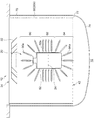
図3は、本発明の第3実施形態に係るクライオポンプ10の主要部を概略的に示す。第3実施形態に係るクライオポンプ10は、放射シールド30がシールド円筒部材30aのみから成りシールド環状プレート30bを有しない点で、第2実施形態に係るクライオポンプ10と異なる。よって、シールド底部開口42は、シールド円筒部材30aのハウジング底部74側の開放端77によって定められている。つまり、放射シールド30は、シールド底部を有しない。この場合、放射シールド30は単純な形状であるため、製造が容易である。
FIG. 3 schematically shows a main part of the
また、第3実施形態に係るクライオポンプ10は、第2クライオパネルユニット20についても、第2実施形態に係るクライオポンプ10と異なる。第2クライオパネルユニット20は、吸気口12側に配置されたクライオパネルユニット上部90、クライオパネルユニット中間部92、およびハウジング底部74側に配置されたクライオパネルユニット下部94を備える。クライオパネルユニット中間部92はクライオパネルユニット上部90とクライオパネルユニット下部94の間に配置されている。クライオパネルユニット上部90は、パネル取付部材62から吸気口12に向けて放射状に突き出す複数のクライオパネル90aを備える。クライオパネルユニット中間部92は複数の平板状のクライオパネル92aを備える。クライオパネルユニット下部94は、パネル取付部材62からハウジング底部74に向けて放射状に突き出す複数のクライオパネル94aを備える。
Moreover, the
図3に示されるように、シールド底部開口42の直径(つまりシールド主開口34の直径)は、第2クライオパネルユニット20からハウジング底部74への距離より大きい。
As shown in FIG. 3, the diameter of the shield bottom opening 42 (that is, the diameter of the shield main opening 34) is larger than the distance from the
シールド底部開口42は、第2冷却ステージ24より大きい。シールド底部開口42の面積は、第2冷却ステージ24の軸方向投影面積より大きい。第2冷却ステージ24はクライオポンプ10の中心軸A上に位置するから、シールド底部開口42は、クライオポンプ10の中心軸Aに沿って見たとき第2冷却ステージ24を取り囲む。シールド底部開口42の直径は、第2冷却ステージ24の寸法より大きい。ここで、第2冷却ステージ24の寸法は、例えば、冷凍機16の中心軸に沿って見たときの第2冷却ステージ24の外形寸法であり、例えば第2冷却ステージ24の直径または径方向の幅である。シールド底部開口42が第2冷却ステージ24より大きくてもよいことは、第1実施形態および第2実施形態においても同様である。
The shield bottom opening 42 is larger than the
パネル取付部材62は、第2冷却ステージ24の両側にそれぞれ取り付けられる一組の取付板を有する。これら取付板には少なくともクライオパネルユニット中間部92が取り付けられている。シールド底部開口42の直径は、パネル取付部材62の寸法(例えば一組の取付板の間隔)より大きくてもよい。
The
第3実施形態に係るクライオポンプ10によっても、第1および第2実施形態に係るクライオポンプ10と同様の作用効果を奏することができる。
Also with the
以上、本発明を実施例にもとづいて説明した。本発明は上記実施形態に限定されず、種々の設計変更が可能であり、様々な変形例が可能であること、またそうした変形例も本発明の範囲にあることは、当業者に理解されるところである。 In the above, this invention was demonstrated based on the Example. It will be understood by those skilled in the art that the present invention is not limited to the above-described embodiment, and various design changes are possible, various modifications are possible, and such modifications are within the scope of the present invention. By the way.
シールド底部開口42の形状は、円形に限られず、矩形や楕円その他任意の形状であってもよい。いずれにしても、シールド底部開口42の寸法(例えば直径または幅など)は、第2クライオパネルユニット20からハウジング底部74への距離より大きい。
The shape of the shield bottom opening 42 is not limited to a circle, and may be a rectangle, an ellipse, or any other shape. In any case, the dimension (for example, diameter or width) of the shield bottom opening 42 is larger than the distance from the
第1から第3の実施形態に言及した放射シールド30と第2クライオパネルユニット20との任意の組み合わせが可能である。例えば、第1実施形態の一体型の放射シールド30は、第2実施形態の入れ子状配列の第2クライオパネルユニット20と組み合わされてもよいし、第3実施形態の第2クライオパネルユニット20と組み合わされてもよい。同様に、第2実施形態の二部構成の放射シールド30は、第1実施形態または第3実施形態の第2クライオパネルユニット20と組み合わされてもよい。第3実施形態の両端開放円筒状の放射シールド30は、第1実施形態または第2実施形態の第2クライオパネルユニット20と組み合わされてもよい。
Any combination of the
10 クライオポンプ、 16 冷凍機、 21 冷凍機構造部、 22 第1冷却ステージ、 24 第2冷却ステージ、 30 放射シールド、 30a シールド円筒部材、 30b シールド環状プレート、 34 シールド主開口、 36 シールド前端、 38 シールド底部、 40 シールド側部、 42 シールド底部開口、 44 シールド側部開口、 60 クライオパネル、 70 クライオポンプハウジング、 74 ハウジング底部、 76 プレート外周、 78 プレート内周、 80 クライオパネル、 82 視線。
DESCRIPTION OF
Claims (6)
前記第2冷却ステージに熱的に結合されているクライオパネルユニットと、
シールド主開口、シールド側部開口、およびシールド底部開口を有し、前記第2冷却ステージおよび前記クライオパネルユニットを包囲する放射シールドであって、前記冷凍機構造部が前記シールド側部開口に挿通された状態で前記第1冷却ステージに熱的に結合されている放射シールドと、
前記シールド底部開口に面するハウジング底部を有し、前記放射シールドを包囲するクライオポンプハウジングと、を備え、
前記シールド底部開口の寸法は、前記クライオパネルユニットから前記ハウジング底部への距離より大きいことを特徴とするクライオポンプ。 A first cooling stage cooled to a first cooling temperature, a second cooling stage cooled to a second cooling temperature lower than the first cooling temperature, and the second cooling stage structurally as the first cooling stage A refrigerator having a refrigerator structure part to be supported;
A cryopanel unit thermally coupled to the second cooling stage;
A radiation shield having a shield main opening, a shield side opening, and a shield bottom opening, surrounding the second cooling stage and the cryopanel unit, wherein the refrigerator structure portion is inserted into the shield side opening. A radiation shield thermally coupled to the first cooling stage in a closed state;
A cryopump housing having a housing bottom facing the shield bottom opening and surrounding the radiation shield;
The cryopump according to claim 1, wherein a dimension of the shield bottom opening is larger than a distance from the cryopanel unit to the housing bottom.
前記シールド底部開口は、前記シールド前端から前記クライオパネルユニットへの視線と前記放射シールドとの交差により定まる境界の内側に位置することを特徴とする請求項1に記載のクライオポンプ。 The radiation shield includes a shield front end defining the shield main opening;
2. The cryopump according to claim 1, wherein the shield bottom opening is located inside a boundary determined by an intersection of a line of sight from the front end of the shield to the cryopanel unit and the radiation shield.
Priority Applications (5)
| Application Number | Priority Date | Filing Date | Title |
|---|---|---|---|
| JP2016002490A JP6629074B2 (en) | 2016-01-08 | 2016-01-08 | Cryopump |
| CN201611235169.0A CN106958519B (en) | 2016-01-08 | 2016-12-28 | Cryogenic pump |
| KR1020160180876A KR102483239B1 (en) | 2016-01-08 | 2016-12-28 | Cryopump |
| TW105143931A TWI614406B (en) | 2016-01-08 | 2016-12-29 | Cryopump |
| US15/399,488 US10550830B2 (en) | 2016-01-08 | 2017-01-05 | Cryopump |
Applications Claiming Priority (1)
| Application Number | Priority Date | Filing Date | Title |
|---|---|---|---|
| JP2016002490A JP6629074B2 (en) | 2016-01-08 | 2016-01-08 | Cryopump |
Publications (2)
| Publication Number | Publication Date |
|---|---|
| JP2017122414A true JP2017122414A (en) | 2017-07-13 |
| JP6629074B2 JP6629074B2 (en) | 2020-01-15 |
Family
ID=59274790
Family Applications (1)
| Application Number | Title | Priority Date | Filing Date |
|---|---|---|---|
| JP2016002490A Active JP6629074B2 (en) | 2016-01-08 | 2016-01-08 | Cryopump |
Country Status (5)
| Country | Link |
|---|---|
| US (1) | US10550830B2 (en) |
| JP (1) | JP6629074B2 (en) |
| KR (1) | KR102483239B1 (en) |
| CN (1) | CN106958519B (en) |
| TW (1) | TWI614406B (en) |
Families Citing this family (2)
| Publication number | Priority date | Publication date | Assignee | Title |
|---|---|---|---|---|
| CN107524579A (en) * | 2017-09-26 | 2017-12-29 | 安徽万瑞冷电科技有限公司 | A kind of cryogenic pump |
| JP2022117029A (en) * | 2021-01-29 | 2022-08-10 | アルバック・クライオ株式会社 | cryopump |
Citations (4)
| Publication number | Priority date | Publication date | Assignee | Title |
|---|---|---|---|---|
| JPH04187873A (en) * | 1990-11-20 | 1992-07-06 | Kobe Steel Ltd | Evacuation device |
| JPH0633874A (en) * | 1992-07-16 | 1994-02-08 | Ulvac Kuraio Kk | Cryopump device equipped with turbomolecular pump |
| US20050155358A1 (en) * | 2004-01-21 | 2005-07-21 | Helix Technology Corp. | Method and apparatus for detecting and measuring state of fullness in cryopumps |
| JP2010516939A (en) * | 2007-01-17 | 2010-05-20 | ブルックス オートメーション インコーポレイテッド | Large capacity cryopump with no pressure burst |
Family Cites Families (10)
| Publication number | Priority date | Publication date | Assignee | Title |
|---|---|---|---|---|
| JPS59174379A (en) | 1983-03-24 | 1984-10-02 | Tokyo Juki Ind Co Ltd | Control system for operation of printer |
| US7721553B2 (en) * | 2006-07-18 | 2010-05-25 | Siemens Energy, Inc. | Method and apparatus for detecting a flashback condition in a gas turbine |
| WO2009013807A1 (en) | 2007-07-23 | 2009-01-29 | Sumitomo Heavy Industries, Ltd. | Cryopump |
| JP5557786B2 (en) * | 2011-04-05 | 2014-07-23 | 住友重機械工業株式会社 | Lid structure for cryopump, cryopump, method for starting cryopump, and method for storing cryopump |
| JP5460644B2 (en) * | 2011-05-12 | 2014-04-02 | 住友重機械工業株式会社 | Cryopump |
| JP6013886B2 (en) * | 2012-11-13 | 2016-10-25 | 住友重機械工業株式会社 | Cryopump |
| JP6057782B2 (en) * | 2013-03-05 | 2017-01-11 | 住友重機械工業株式会社 | Cryopump |
| JP6338403B2 (en) * | 2013-03-25 | 2018-06-06 | 住友重機械工業株式会社 | Cryopump and vacuum exhaust method |
| JP6076843B2 (en) * | 2013-06-14 | 2017-02-08 | 住友重機械工業株式会社 | Cryopump |
| JP6084119B2 (en) * | 2013-05-27 | 2017-02-22 | 住友重機械工業株式会社 | Cryopump |
-
2016
- 2016-01-08 JP JP2016002490A patent/JP6629074B2/en active Active
- 2016-12-28 CN CN201611235169.0A patent/CN106958519B/en active Active
- 2016-12-28 KR KR1020160180876A patent/KR102483239B1/en active IP Right Grant
- 2016-12-29 TW TW105143931A patent/TWI614406B/en active
-
2017
- 2017-01-05 US US15/399,488 patent/US10550830B2/en active Active
Patent Citations (4)
| Publication number | Priority date | Publication date | Assignee | Title |
|---|---|---|---|---|
| JPH04187873A (en) * | 1990-11-20 | 1992-07-06 | Kobe Steel Ltd | Evacuation device |
| JPH0633874A (en) * | 1992-07-16 | 1994-02-08 | Ulvac Kuraio Kk | Cryopump device equipped with turbomolecular pump |
| US20050155358A1 (en) * | 2004-01-21 | 2005-07-21 | Helix Technology Corp. | Method and apparatus for detecting and measuring state of fullness in cryopumps |
| JP2010516939A (en) * | 2007-01-17 | 2010-05-20 | ブルックス オートメーション インコーポレイテッド | Large capacity cryopump with no pressure burst |
Also Published As
| Publication number | Publication date |
|---|---|
| KR20170083487A (en) | 2017-07-18 |
| KR102483239B1 (en) | 2022-12-29 |
| CN106958519A (en) | 2017-07-18 |
| US20170198684A1 (en) | 2017-07-13 |
| TW201725321A (en) | 2017-07-16 |
| TWI614406B (en) | 2018-02-11 |
| CN106958519B (en) | 2019-03-08 |
| JP6629074B2 (en) | 2020-01-15 |
| US10550830B2 (en) | 2020-02-04 |
Similar Documents
| Publication | Publication Date | Title |
|---|---|---|
| JP6710604B2 (en) | Cryopump | |
| JP6338403B2 (en) | Cryopump and vacuum exhaust method | |
| JP6076843B2 (en) | Cryopump | |
| CN110291291B (en) | Low-temperature pump | |
| WO2018147187A1 (en) | Cryopump | |
| JP6629074B2 (en) | Cryopump | |
| JP7339950B2 (en) | cryopump | |
| JP2010048132A (en) | Cryopump | |
| JP6913049B2 (en) | Cryopump | |
| JP2010196632A (en) | Cryopump | |
| JP6857046B2 (en) | Cryopump | |
| CN110234878B (en) | Low-temperature pump | |
| WO2023145296A1 (en) | Cryopump | |
| JP2022016630A (en) | Cryopump |
Legal Events
| Date | Code | Title | Description |
|---|---|---|---|
| A621 | Written request for application examination |
Free format text: JAPANESE INTERMEDIATE CODE: A621 Effective date: 20180612 |
|
| A977 | Report on retrieval |
Free format text: JAPANESE INTERMEDIATE CODE: A971007 Effective date: 20190422 |
|
| A131 | Notification of reasons for refusal |
Free format text: JAPANESE INTERMEDIATE CODE: A131 Effective date: 20190507 |
|
| A521 | Request for written amendment filed |
Free format text: JAPANESE INTERMEDIATE CODE: A523 Effective date: 20190614 |
|
| A131 | Notification of reasons for refusal |
Free format text: JAPANESE INTERMEDIATE CODE: A131 Effective date: 20191105 |
|
| A521 | Request for written amendment filed |
Free format text: JAPANESE INTERMEDIATE CODE: A523 Effective date: 20191119 |
|
| TRDD | Decision of grant or rejection written | ||
| A01 | Written decision to grant a patent or to grant a registration (utility model) |
Free format text: JAPANESE INTERMEDIATE CODE: A01 Effective date: 20191203 |
|
| A61 | First payment of annual fees (during grant procedure) |
Free format text: JAPANESE INTERMEDIATE CODE: A61 Effective date: 20191204 |
|
| R150 | Certificate of patent or registration of utility model |
Ref document number: 6629074 Country of ref document: JP Free format text: JAPANESE INTERMEDIATE CODE: R150 |