JP2017120384A - Virtual image display device - Google Patents
Virtual image display device Download PDFInfo
- Publication number
- JP2017120384A JP2017120384A JP2016212637A JP2016212637A JP2017120384A JP 2017120384 A JP2017120384 A JP 2017120384A JP 2016212637 A JP2016212637 A JP 2016212637A JP 2016212637 A JP2016212637 A JP 2016212637A JP 2017120384 A JP2017120384 A JP 2017120384A
- Authority
- JP
- Japan
- Prior art keywords
- light
- light guide
- display device
- image display
- guide member
- Prior art date
- Legal status (The legal status is an assumption and is not a legal conclusion. Google has not performed a legal analysis and makes no representation as to the accuracy of the status listed.)
- Granted
Links
Images


Abstract
Description
本発明は、画像表示装置(映像素子)によって形成された映像を観察者に提示する虚像表示装置に関する。 The present invention relates to a virtual image display device that presents an image formed by an image display device (video element) to an observer.
観察者の頭部に装着するヘッドマウントディスプレイ(以下、HMDとも言う)等の虚像表示装置に組み込まれる光学系として様々なものが提案されている(例えば、特許文献1参照)。 Various optical systems have been proposed as an optical system incorporated in a virtual image display device such as a head-mounted display (hereinafter also referred to as HMD) that is worn on the observer's head (for example, see Patent Document 1).
このような虚像表示装置として、例えば、画像光(映像光)を視認させるとともに観察者に外界像を視認させるシースルーの光学系として、映像光を複数の反射面で反射させて導光する導光部材を適用するものが知られている(例えば特許文献1等参照)。上記特許文献1等では、複数の反射面として隣り合っている面(例えば特許文献1における図3の第1面S11と第4面S14)が存在する。
As such a virtual image display device, for example, as a see-through optical system for visually recognizing image light (video light) and allowing an observer to visually recognize an external image, light guide that reflects and guides video light by a plurality of reflecting surfaces. A member to which a member is applied is known (see, for example, Patent Document 1). In the above-mentioned
しかしながら、上記のようなシースルータイプのHMD等では、導光部材に入り込む外光が、導光部材の内部で意図しない反射をして導光部材の内部を導光し、観察者に視認されてしまう、すなわちゴースト光となる可能性がある。特に、導光部材のうち、隣り合う反射面の接続部分においては、その形状によっては、導光部材に入り込んだ外光の一部の成分が反射されて導光方向(映像光の光路下流側に向かう方向)に導光されてしまう場合が生じ得る。特に、装置の小型化を図る上で、ゴースト光に関する余分な成分の適切な処理は重要となる。 However, in the see-through type HMD as described above, external light entering the light guide member is reflected unintentionally inside the light guide member and guided inside the light guide member, and is visually recognized by an observer. That is, ghost light. In particular, in the connection part of the adjacent reflecting surfaces in the light guide member, depending on the shape, a part of the component of the external light that has entered the light guide member is reflected to guide the light guide direction (downstream of the optical path of the image light) In some cases, the light is guided in the direction toward the head. In particular, in order to reduce the size of the apparatus, it is important to appropriately process extra components related to ghost light.
本発明は、シースルータイプの虚像表示装置であって、上記したようなゴースト光の発生を抑制して良好な画像視認性を確保できる虚像表示装置を提供することを目的とする。 An object of the present invention is to provide a virtual image display device that is a see-through type virtual image display device and that can suppress the generation of ghost light as described above and ensure good image visibility.
本発明に係る第1の虚像表示装置は、映像光を生じさせる映像素子と、複数の反射面を有して内面で反射させることにより映像素子からの映像光を導光するとともに、映像光と外界光とを重複して視認させる導光部材とを備え、導光部材は、複数の反射面のうち外界光の入射側と反対側に配置されかつ隣り合う反射面として、第1反射面と、第1反射面よりも映像光の射出側に位置する第2反射面とを有し、第1反射面と第2反射面とを繋ぐ接続部において、第1反射面を第2反射面以上に張り出させている。 A first virtual image display device according to the present invention includes a video element that generates video light, a plurality of reflection surfaces that are reflected by an inner surface to guide video light from the video element, and video light and A light guide member that overlaps and visually recognizes external light, and the light guide member is disposed on the side opposite to the incident side of the external light and is adjacent to the first reflective surface. And a second reflection surface located on the image light exit side from the first reflection surface, and the first reflection surface is equal to or higher than the second reflection surface in a connecting portion connecting the first reflection surface and the second reflection surface. Overhangs.
上記虚像表示装置では、映像光を導光する複数の反射面のうち観察者側において隣り合う一対の反射面である第1反射面と第2反射面とを繋ぐ接続部において、第1反射面を、第1反射面よりも映像光の射出側に位置する第2反射面以上に張り出させている。言い換えると、虚像表示装置を装着した場合において、映像光の光路上流側にある面が光路下流側にある面以上に観察者側に出っ張った状態となっている。この場合、両反射面を繋ぐ接続部は、第1反射面から第2反射面にかけて観察者に近い側から遠ざかる側に向かって延びるような形状となる。これにより、導光部材に対して観察者と反対側から観察者側に向かって入射する成分である外光が、当該接続部に入射しその一部が反射されても、反射された成分は、そのまま反射されて導光部材の外部に向かうか映像光の光路上流側に向かうものとなり、光路下流側には向かないあるいは向きにくくなる。すなわち、導光部材の内部を光路下流側に向かって導光し、観察者に視認されてしまいゴースト光となる、ということを抑制でき、良好な画像視認性を確保できる。 In the virtual image display device, the first reflection surface is a connection portion that connects the first reflection surface and the second reflection surface, which are a pair of reflection surfaces adjacent to each other on the viewer side, among the plurality of reflection surfaces that guide video light. Is projected beyond the second reflecting surface located on the image light emitting side from the first reflecting surface. In other words, when the virtual image display device is attached, the surface on the upstream side of the optical path of the image light protrudes to the viewer side more than the surface on the downstream side of the optical path. In this case, the connecting portion that connects the two reflecting surfaces has a shape that extends from the first reflecting surface to the second reflecting surface toward the side away from the viewer. As a result, even if external light that is a component incident on the light guide member from the side opposite to the viewer toward the viewer is incident on the connection portion and part of the light is reflected, the reflected component is Then, the light is reflected as it is and goes to the outside of the light guide member or toward the upstream side of the optical path of the image light, and is not directed to the downstream side of the optical path or is difficult to face. That is, it is possible to prevent the inside of the light guide member from being guided toward the downstream side of the optical path and being viewed by an observer and resulting in ghost light, and good image visibility can be ensured.
本発明の具体的な側面では、第1反射面は、自由曲面であり、第2反射面は、平坦面である。この場合、第1反射面においては、収差補正を抑制する機能をもたせ、第2反射面においては、シースルーにおける外界光の視認性を良好にできる。 In a specific aspect of the present invention, the first reflecting surface is a free-form surface, and the second reflecting surface is a flat surface. In this case, the first reflecting surface has a function of suppressing aberration correction, and the second reflecting surface can improve the visibility of external light in the see-through.
本発明の別の側面では、接続部において、第2反射面に対する第1反射面の張出し方向の厚さnは、接続部の全体に亘って0≦n≦2mmで維持されている。この場合、接続部において第1反射面を第2反射面以上に観察者側に張り出させた状態に維持するとともに接続部が大きくなりすぎることで外光が接続部において意図しない反射をすることを抑制できる。また、接続部が目立つことを抑制できる。 In another aspect of the present invention, in the connecting portion, the thickness n in the protruding direction of the first reflecting surface with respect to the second reflecting surface is maintained at 0 ≦ n ≦ 2 mm over the entire connecting portion. In this case, the connection portion keeps the first reflecting surface overhanging the viewer side more than the second reflecting surface, and the connection portion becomes too large so that external light reflects unintentionally at the connection portion. Can be suppressed. Moreover, it can suppress that a connection part is conspicuous.
本発明のさらに別の側面では、接続部は、第1反射面と第2反射面との間を連続的に繋ぐ接続面を有する。この場合、接続面に入射した外光の反射成分がゴースト光となることを抑制できる。 In still another aspect of the present invention, the connection portion has a connection surface that continuously connects the first reflection surface and the second reflection surface. In this case, the reflection component of the external light incident on the connection surface can be prevented from becoming ghost light.
本発明のさらに別の側面では、導光部材は、第1反射面と第1反射面を延長した延長面全体とを含む第1表面と、第2反射面と第2反射面を延長した延長面全体とを含む第2表面との間を接続部により繋ぐとともに、繋いだ範囲全体において、第1表面を第2表面以上に張り出させている。この場合、第1反射面や第2反射面を延長した延長面全体において導光部材の内部でのゴースト光の発生を抑制できる。 In still another aspect of the present invention, the light guide member includes a first surface including the first reflection surface and the entire extension surface extending the first reflection surface, and an extension obtained by extending the second reflection surface and the second reflection surface. The second surface including the entire surface is connected to the second surface by a connecting portion, and the first surface is projected beyond the second surface in the entire connected range. In this case, generation | occurrence | production of the ghost light inside a light guide member can be suppressed in the whole extended surface which extended the 1st reflective surface and the 2nd reflective surface.
本発明に係る第2の虚像表示装置は、映像光を生じさせる映像素子と、複数の反射面を有して内面で反射させることにより映像素子からの映像光を導光するとともに、映像光と外界光とを重複して視認させる導光部材とを備え、導光部材は、複数の反射面のうち外界光の入射側と反対側に配置されかつ隣り合う反射面として、第1反射面と、第1反射面よりも映像光の射出側に位置する第2反射面とを有するとともに、第1反射面と第2反射面とを繋ぐ接続部を有し、接続部は、第1反射面が第2反射面よりも凹んで凹状部分を形成する箇所において、凹状部分に応じて第2反射面に対して所定値以下の傾斜角度を保持する傾斜接続面を形成する。 A second virtual image display device according to the present invention includes a video element that generates video light, a plurality of reflective surfaces that are reflected on the inner surface to guide the video light from the video element, and the video light A light guide member that overlaps and visually recognizes external light, and the light guide member is disposed on the side opposite to the incident side of the external light and is adjacent to the first reflective surface. And a second reflecting surface located on the image light exit side from the first reflecting surface, and a connecting portion that connects the first reflecting surface and the second reflecting surface. The connecting portion is a first reflecting surface. However, at the location where the concave portion is formed to be recessed from the second reflective surface, an inclined connection surface is formed that maintains an inclination angle of a predetermined value or less with respect to the second reflective surface in accordance with the concave portion.
上記虚像表示装置では、映像光を導光する複数の反射面のうち観察者側において隣り合う一対の反射面である第1反射面と第2反射面とを繋ぐ接続部が、第1反射面において第2反射面よりも凹んで形成される凹状部分に応じて第2反射面に対して所定値以下の傾斜角度を保持する傾斜接続面を形成している。これにより、導光部材に対して観察者と反対側から観察者側に向かって入射する成分である外光が、当該接続部傾斜接続面に入射しその一部が反射されても、反射された成分の光路を調整して、当該成分が観察者に視認されてしまいゴースト光となる、ということを抑制でき、良好な画像視認性を確保できる。 In the virtual image display device, the connecting portion that connects the first reflecting surface and the second reflecting surface, which are a pair of reflecting surfaces adjacent to each other on the viewer side, among the plurality of reflecting surfaces that guide video light is the first reflecting surface. An inclined connection surface that holds an inclination angle equal to or smaller than a predetermined value with respect to the second reflecting surface is formed according to the concave portion formed to be recessed from the second reflecting surface. As a result, external light that is a component incident on the light guide member from the side opposite to the observer toward the observer side is reflected even if it is incident on the connecting portion inclined connection surface and part of the light is reflected. By adjusting the optical path of each component, it can be suppressed that the component is visually recognized by the observer and becomes ghost light, and good image visibility can be secured.
本発明の具体的な側面では、接続部において、第2反射面に対する傾斜接続面の傾斜角度は、第1反射面における凹状部分の第2反射面に対する差と、接続部の導光部材の導光方向についての幅とに応じて定まる。この場合、凹状部分の形状や凹状部分の導光方向についての幅によって所望の傾斜角度となる傾斜接続面を形成できる。 In a specific aspect of the present invention, in the connection portion, the inclination angle of the inclined connection surface with respect to the second reflection surface is different from the difference between the concave portion of the first reflection surface with respect to the second reflection surface and the guide of the light guide member of the connection portion. It depends on the width of the light direction. In this case, an inclined connection surface having a desired inclination angle can be formed according to the shape of the concave portion and the width of the concave portion in the light guide direction.
本発明の別の側面では、接続部の導光部材の導光方向についての幅は、1.7mm以上である。この場合、所望の傾斜角度となる傾斜接続面を形成するために十分なものにできる。 In another aspect of the present invention, the width of the connection portion in the light guide direction of the light guide member is 1.7 mm or more. In this case, it is sufficient to form an inclined connection surface having a desired inclination angle.
本発明のさらに別の側面では、接続部において、第2反射面に対する第1反射面の張出し方向の厚さnは、接続部の全体に亘って−0.2≦n≦2mmで維持されている。この場合、接続部において第1反射面を第2反射面以上に観察者側に張り出すところだけでなく、第1反射面が第2反射面よりも凹んだ箇所が存在する箇所も存在するが、かかる箇所での第1反射面と第2反射面との位置の差が大きくなりすぎるすなわち接続部が大きくなりすぎてしまって外光が接続部において意図しない反射をしてしまう、といったことを抑制できる。また、接続部が目立つことを抑制できる。 In yet another aspect of the present invention, in the connection portion, the thickness n in the protruding direction of the first reflection surface with respect to the second reflection surface is maintained at −0.2 ≦ n ≦ 2 mm over the entire connection portion. Yes. In this case, in addition to the location where the first reflecting surface protrudes beyond the second reflecting surface to the viewer side at the connection portion, there are also locations where the first reflecting surface is recessed from the second reflecting surface. The difference in position between the first reflecting surface and the second reflecting surface at such a location becomes too large, that is, the connecting portion becomes too large and external light reflects unintentionally at the connecting portion. Can be suppressed. Moreover, it can suppress that a connection part is conspicuous.
本発明のさらに別の側面では、第2反射面に対する傾斜接続面の最大傾斜角度θは、複数の反射面のうち第1反射面及び第2反射面に対向する第3反射面における導光部材の導光方向の長さについて接続部の中心よりも映像光の射出側の長さをL2とし、第3反射面から入射した外光の屈折角をα1とし、第2反射面に垂直な方向についての導光部材の厚みをDとした場合に、
![]()
![]()
本発明のさらに別の側面では、第2反射面に対する傾斜接続面の最大傾斜角度は、6.9°以下である。この場合、傾斜接続面の傾斜角度をゴースト光の抑制のために十分小さいものにできる。 In still another aspect of the invention, the maximum inclination angle of the inclined connection surface with respect to the second reflecting surface is 6.9 ° or less. In this case, the inclination angle of the inclined connection surface can be made sufficiently small to suppress ghost light.
本発明のさらに別の側面では、接続部は、砂刷りまたは黒塗りされている。この場合、接続部に入射する外光を吸収または拡散させて、外光に起因するゴースト光の発生を抑制できる。 In yet another aspect of the present invention, the connecting portion is sand-printed or black-painted. In this case, external light incident on the connection portion can be absorbed or diffused, and generation of ghost light due to external light can be suppressed.
本発明のさらに別の側面では、第1反射面及び第2反射面に対向する反射面は、導光部材の導光方向に関して接続部よりも映像光の入射側において砂刷りまたは黒塗りされている部分を有する。この場合、第1反射面及び第2反射面に対向する反射面から入射する外光を吸収または拡散させて、外光に起因するゴースト光の発生を抑制できる。 In still another aspect of the present invention, the reflecting surfaces facing the first reflecting surface and the second reflecting surface are sand-printed or black-coated on the incident side of the image light with respect to the light guide direction of the light guide member. It has a part. In this case, the generation of ghost light due to the external light can be suppressed by absorbing or diffusing the external light incident from the reflective surface facing the first reflective surface and the second reflective surface.
本発明のさらに別の側面では、導光部材は、非軸対称な曲面を2面以上含み、導光部材を構成する複数の反射面のうち第1面と第3面とは、対向するように配置され、第1面と第3面とを通過させて外界を視認した時に、視度が略0になっており、映像素子からの映像光は、第3面で全反射され、第1面で全反射され、第2面で反射された後、第1面を透過して、観察側に到達する。この場合、映像光による画像に外界を重畳して視認させるシースルーの状態を良好に維持しつつ、装置の小型化を図ることができる。 In still another aspect of the present invention, the light guide member includes two or more non-axisymmetric curved surfaces, and the first surface and the third surface of the plurality of reflective surfaces constituting the light guide member are opposed to each other. When the external world is visually recognized through the first surface and the third surface, the diopter is substantially 0, and the image light from the image element is totally reflected by the third surface, After being totally reflected by the surface and reflected by the second surface, the light passes through the first surface and reaches the observation side. In this case, it is possible to reduce the size of the apparatus while maintaining a good see-through state in which an external environment is superimposed on the image of the video light.
本発明のさらに別の側面では、導光部材は、第1面と隣り合い、かつ、映像光を反射して第3面に入射させる第4面を含み、第1反射面は、第4面であり、第2反射面は、第1面である。この場合、小型化された導光部材の内部でのゴースト光の発生を抑制できる。 In still another aspect of the present invention, the light guide member includes a fourth surface that is adjacent to the first surface and reflects the image light to be incident on the third surface, and the first reflective surface is the fourth surface. And the second reflecting surface is the first surface. In this case, generation of ghost light inside the miniaturized light guide member can be suppressed.
本発明のさらに別の側面では、映像素子からの映像光を導光部材に入射させる投射光学系をさらに備える。 In still another aspect of the present invention, the optical system further includes a projection optical system that causes the image light from the image element to enter the light guide member.
本発明のさらに別の側面では、投射光学系は、少なくとも1面の非軸対称非球面を含み、1面の非軸対称非球面は、映像素子の光射出面において異なる隅領域の2点からそれぞれ射出された映像光の光線束のうち観察者の眼に到達すべき成分が互いに交わらない位置に配置されている。この場合、投射光学系を含む光学系全体においてさらに小型化し、延いては装置全体を小型化することができる。 In yet another aspect of the present invention, the projection optical system includes at least one non-axisymmetric aspheric surface, and the one non-axisymmetric aspheric surface is formed from two points in different corner regions on the light exit surface of the image element. The components that should reach the observer's eyes in the bundle of emitted image light beams are arranged at positions where they do not cross each other. In this case, the entire optical system including the projection optical system can be further downsized, and thus the entire apparatus can be downsized.
本発明のさらに別の側面では、映像素子の光射出面の法線方向に対して垂直で、かつ、導光部材の導光方向に対応する方向を第1方向とし、法線方向と第1方向とに対して垂直な方向を第2方向とした場合に、投射光学系は、映像素子の中心を通り法線方向に平行な投射光学系光軸に対して垂直に配置され、かつ、第1方向に平行に延びて投射光学系光軸に交差する第1軸について線対称で第2方向に平行に延びて投射光学系光軸に交差する第2軸について非線対称な四角形状の開口部、または、投射光学系光軸に対して非垂直に配置されている四角形状の開口部を形成する絞りを有する。 In still another aspect of the present invention, a direction perpendicular to the normal direction of the light exit surface of the image element and corresponding to the light guide direction of the light guide member is defined as a first direction, and the normal direction and the first When the direction perpendicular to the direction is the second direction, the projection optical system is disposed perpendicular to the optical axis of the projection optical system passing through the center of the image element and parallel to the normal direction, and A quadrangular aperture that extends parallel to one direction and is axisymmetric about a first axis that intersects the optical axis of the projection optical system, and is non-axisymmetric about a second axis that extends parallel to the second direction and intersects the optical axis of the projection optical system Or a diaphragm that forms a rectangular opening that is arranged non-perpendicular to the optical axis of the projection optical system.
本発明のさらに別の側面では、導光部材において、光入射側に配置される光入射部と投射光学系の投射光学系光軸との交点から光射出側に配置される光射出部と観察者の視線の基準として想定される視線軸との交点までの距離が48mm以下である。この場合、HMDとして適用するにあたって長時間の使用やデザイン性等の観点から、装置の十分な小型化を図ることができる。 In still another aspect of the present invention, in the light guide member, the light emitting unit disposed on the light emitting side from the intersection of the light incident unit disposed on the light incident side and the projection optical system optical axis of the projection optical system, and observation The distance to the intersection with the visual axis assumed as the reference of the visual line of the person is 48 mm or less. In this case, when applied as an HMD, the apparatus can be sufficiently downsized from the viewpoint of long-time use, design, and the like.
本発明のさらに別の側面では、導光部材は、映像素子からの映像光と外界光との部分的な反射及び透過を行う半透過反射部を有し、半透過反射部を挟んで光透過部材と接続されている。この場合、導光部材は、光透過部材と協働して半透過反射部を挟んだ構造を構成することで、映像光を視認させることができるとともに、観察者に外界像をシースルーで視認又は観察させることができる。 In yet another aspect of the present invention, the light guide member has a semi-transmissive reflection portion that partially reflects and transmits image light from the image element and external light, and transmits light with the semi-transmissive reflection portion interposed therebetween. Connected to the member. In this case, the light guide member has a structure in which the transflective portion is sandwiched in cooperation with the light transmissive member, so that the image light can be visually recognized and the external image can be visually confirmed or viewed through the observer. Can be observed.
本発明のさらに別の側面では、導光部材は、左右一対で構成され、左右一対の導光部材と光透過部材とは、左右一対の導光部材により光透過部材を挟んで接続して一体の光学部材となっている。この場合、両眼視による画像の認識が可能であるとともに、両眼視のための位置合わせを光透過部材により簡易かつ正確に行うことができる。 In still another aspect of the present invention, the light guide member is configured as a pair of left and right, and the pair of left and right light guide members and the light transmission member are integrally connected with the light transmission member interposed between the pair of left and right light guide members. This is an optical member. In this case, it is possible to recognize an image by binocular vision, and it is possible to easily and accurately perform alignment for binocular vision by the light transmitting member.
〔第1実施形態〕
以下、図1等を参照しつつ、本発明の第1実施形態に係る虚像表示装置について詳細に説明する。
[First Embodiment]
Hereinafter, the virtual image display device according to the first embodiment of the present invention will be described in detail with reference to FIG. 1 and the like.
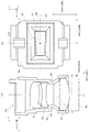
図1に示すように、本実施形態の虚像表示装置100は、眼鏡のような外観を有するヘッドマウントディスプレイであり、この虚像表示装置100を装着した観察者又は使用者に対して虚像による画像光(映像光)を視認させることができるとともに、観察者に外界像をシースルーで視認又は観察させることができる虚像表示装置である。虚像表示装置100は、観察者の眼前を透視可能に覆う第1及び第2光学部材101a,101bと、両光学部材101a,101bを支持する枠部102と、枠部102の左右両端から後方のつる部分(テンプル)104にかけての部分に付加された第1及び第2像形成本体部105a,105bとを備える。ここで、図面上で左側の第1光学部材101aと第1像形成本体部105aとを組み合わせた第1表示装置100Aは、右眼用の虚像を形成する部分であり、単独でも虚像表示装置として機能する。また、図面上で右側の第2光学部材101bと第2像形成本体部105bとを組み合わせた第2表示装置100Bは、左眼用の虚像を形成する部分であり、単独でも虚像表示装置として機能する。なお、図2を図1と比較することで、例えば第1及び第2像形成本体部105a,105bは、投射光学系である投射レンズ30や、画像生成部81を含む画像表示装置80(映像素子)でそれぞれ構成されることが分かる。図2は、左眼用の表示装置について図示したものであり、右眼用の表示装置については省略しているが、右眼用の表示装置についても同様の構造を有している。なお、上記の他、観察者の鼻に当接することによって枠部102を支持する役割を有する鼻受部40が設けられている。
As shown in FIG. 1, the virtual
図2に示すように、表示装置100Bは、投影用の光学系である投射透視装置70と、映像光を形成する画像表示装置80とを備えるものと見ることができる。投射透視装置70は、第2光学部材101b又は導光装置20と、結像用の投射レンズ30とを備え、画像表示装置80によって形成された画像を虚像として観察者の眼に投射する役割を有する。言い換えると、投射透視装置70は、画像表示装置80に形成される画像光(映像光)を射出する面である画像面OIからの光を導光して観察者に虚像を視認させる虚像光学系であり、観察者の網膜において再結像させる結像光学系でもある。第2光学部材101b又は導光装置20は、導光及び透視用の導光部材10と、透視用の光透過部材50とで構成されている。なお、第2像形成本体部105bは、画像表示装置80と投射レンズ30とで構成される。また、画像面OIについては、画像表示装置80を構成するパネルのパネル位置を示すパネル面でもある。さらに、画像表示装置80が自発光型の照明の場合、画像面OIは、発光面であるとも言える。
As shown in FIG. 2, the
ここで、上記の光学系の光軸基準について以下のように定める。まず、投射レンズ30についての中心光軸をレンズ光軸(投射光学系光軸)LXとする。また、導光部材10の導光方向に沿って延びる中心軸を導光軸DXとする。導光軸DXは、平板状の導光部材10において、中心を通りかつ平板形状に沿って延びる軸である。さらに、導光部材10の光射出側において、観察者の視線の基準として想定される中心軸を視線軸SXとする。視線軸SXは、眼の位置として想定される眼想定位置EY(以下、実際に眼想定位置EYに眼が置かれた場合も含めるために単に眼EYとも記載する。)の中心位置から導光部材10の光射出範囲の中心に向かって延びる軸である。さらに、導光部材10において、光入射側に配置される光入射部(後述する第2導光部分12)と投射レンズ30のレンズ光軸LXとの交点を交点C1とし、導光部材10の光射出側に配置される光射出部(後述する第1導光部分11)と視線軸SXとの交点を交点C2とする。ここで、図中双方向矢印AAで示す交点C1から交点C2までの距離(間隔)は、48mm以下となっているものとする。また、視線軸SXは、レンズ光軸LXに対して約7°(より正確には6.7°)傾斜している。また、視線軸SXは、導光軸DXに対して垂直な状態から約10°傾斜している。すなわち、視線軸SXと導光軸DXとは、約80°の反射角をなすように交差している。また、上記の場合、レンズ光軸LXと導光軸DXとは、約106.7°の反射角をなすように交差していることになる。
Here, the optical axis reference of the optical system is determined as follows. First, let the center optical axis about the
また、画像表示装置80において、画像面OIは、レンズ光軸LXに対して垂直な面であり、画像面OIの中心をレンズ光軸LXが通過している。ここで、画像面OIに平行な面における水平方向であるx方向(X方向に対応する方向)を第1方向DD1とし、垂直方向であるy方向(Y方向に対応する方向)を第2方向DD2とする。なお、z方向は、画像面OIの法線方向でありレンズ光軸LXが延びる方向である。本実施形態では、画像面OIから射出される映像光の光線束の射出角度は、画像面OIの中心線(レンズ光軸LX)に対して左右(x方向)について非対称である。なお、画像面OIの中心に対して上下方向(y方向)については対称となっている。
In the
画像表示装置80は、有機EL(有機ELパネル)を光源として含む自発光型の照明によりマトリクス状の画素で構成される画像面OIを形成する画像生成部81や、画像生成部81の直近後段に配置されて画像生成部81の画像面OIから射出される映像光GLの各成分について配光の制御を行う配光制御部82のほか、画像生成部81等の動作を制御する駆動制御部(図示略)を有する。なお、詳しくは後述する(図7参照)が、ここでは、画像生成部81の直近後段に配置されるカラーフィルター層CFが、配光制御部82として機能することで、映像光GLについて画像面OIの周辺側から射出される成分光の射出角度が調整されている。例えば、映像光GLの部分光線束のうち、相対的に人体(観察者)に近い内側から射出される部分光線束GLaと相対的に人体から遠い外側から射出される部分光線束GLbとでは、射出角度が異なっている。なお、ここでは、部分光線束GLa,GLbは、映像光GLを構成する光線束のうち観察者の眼に到達すべき成分を意味するものとする。
The
投射レンズ30は、画像表示装置80から射出された映像光GLを導光装置20向けて投射する投射光学系である。本実施形態では、特に、非軸対称な非球面(非軸対称非球面または自由曲面)を有するレンズを画像表示装置80に近い側に配置することで、光学系全体の小型化を可能にしている。ここで、投射レンズ30には、絞りSTが付随して設けられている。絞りSTは、非線対称な四角形状の開口部を形成することで、上記のような非対称に射出される映像光GLの部分光線束GLa等の各成分に対して適切な遮光を行う。なお、絞りSTの詳しい形状・構造等については、図5等を参照して後述する。
The
導光装置20は、既述のように、導光及び透視用の導光部材10と、透視用の光透過部材50とで構成されている。導光部材10は、プリズム型の導光装置20の一部であり、一体の部材であるが、光射出側の第1導光部分11(光射出部)と光入射側の第2導光部分12(光入射部)とに分けて捉えることができる。光透過部材50は、導光部材10の透視機能を補助する部材(補助光学ブロック)であり、導光部材10と一体的に固定され1つの導光装置20となっている。
As described above, the
以下、図2を参照して、虚像光学系である投射透視装置70の役割について、すなわち導光装置20と投射レンズ30とについて詳細に説明する。
Hereinafter, with reference to FIG. 2, the role of the projection see-through
投射レンズ30は、画像表示装置80からの映像光GLを入射させて投射を行う光学系であり、構成要素として、投射光学系光軸であるレンズ光軸LXに沿って3つの光学素子(第1〜第3レンズ)31〜33を備える投射光学系である。光学素子31〜33は、非軸対称な非球面(非軸対称非球面)と軸対称な非球面(軸対称非球面)との双方を含む非球面レンズで構成され、導光部材10の一部と協働して導光部材10の内部に画像生成部81の表示像に対応する中間像を形成する。本実施形態では、特に、光射出側に配置される第1レンズ31の各レンズ面のうち光射出側のレンズ面31aのみならず、光入射側に配置される第3レンズ33の各レンズ面のうち光射出側のレンズ面33aが、非軸対称非球面となっている。なお、投射レンズ30を構成する第1〜第3レンズ31〜33は、例えば鏡筒(図5参照)によって第2像形成本体部105b内に収納・支持されている。また、投射レンズ30は、第1〜第3レンズ31〜33のうち、第2レンズ32と第3レンズ33との間に絞りSTを有している。絞りSTは、投射レンズ30において、映像光GLが最も多く重畳する箇所に配置され、適切に光を絞っている。ここでは、レンズ面に非軸対称な非球面が含まれるため、各部分光線束の成分も複雑に折れ曲がるものとなる。絞りSTは、これに対応した形状や構造を有している。
The
導光装置20は、上述のように、導光部材10と光透過部材50とで構成されている。このうち、導光部材10は、平面視において、鼻に近い中央側(眼前側)の部分が直線状に延びている。導光部材10のうち、鼻に近い中央側つまり光射出側に配置されている第1導光部分11は、光学的な機能を有する側面として、第1面S11と、第2面S12と、第3面S13とを有し、鼻から離れた周辺側つまり光入射側に配置されている第2導光部分12は、光学的な機能を有する側面として、第4面S14と、第5面S15とを有する。このうち、第1面S11と第4面S14とが連続的に隣接し、第3面S13と第5面S15とが連続的に隣接する。また、第1面S11と第3面S13との間に第2面S12が配置され、第4面S14と第5面S15とは大きな角度を成して隣接している。さらに、ここでは、対向した配置となっている第1面S11と第3面S13とが互いに略平行な平面形状となっている。一方、光学的な機能を有する他の面、すなわち第2面S12、第4面S14及び第5面S15は、非軸対称な曲面(自由曲面)となっている。
The
ここで、シースルーにおけるゴースト光の抑制の観点から、導光部材10を構成する複数の反射面について別の捉え方で規定しておく。具体的には、まず、導光部材10における複数の反射面である面S11〜S15のうち、観察者側に配置されかつ隣り合う一対の反射面である第4面S14と第1面S11とについて、相対的に映像光GLの入射側に位置する第4面S14を第1反射面R1とし、相対的に映像光の射出側に位置する第1面S11を第2反射面R2とする。さらに、第1反射面R1と第2反射面R2とを繋ぐ部分を接続部SSとし、特に接続部SSの表面すなわち第1反射面R1と第2反射面R2との間を連続的に滑らかに繋ぐ面を接続面SSaとする。この場合、入射側の第1反射面R1は、自由曲面(第4面S14)であり、射出側の第2反射面R2は、平坦面(第1面S11)であるということになる。本実施形態では、接続部SSにおいて第1反射面R1が第2反射面R2以上に観察者側に張り出している。ここで、接続部において隣り合う2つの面において一の面が他の面よりも観察者側に張り出している、という文言に関して、図示での典型例としては、平坦面である第2反射面R2について、この面を含む平面(基準面)の法線方向を張出し方向DSとし、張出し方向DSに関して第1反射面R1が第2反射面R2に比べて観察者側に出っ張っていることを意味する。さらに、一の面が他の面「以上に」観察者側に張り出しているとは、上記の張出し方向DSに関して、接続部SSの全体のどこにおいても第2反射面R2が第1反射面R1よりも出っ張っている箇所が存在しないことを意味する(図3参照)。なお、ここでは、この張出し方向DSを厚み方向とも呼ぶものとする。
Here, from the viewpoint of suppressing the ghost light in the see-through, the plurality of reflecting surfaces constituting the
詳しくは図3及び図4を参照して後述するが、導光部材10が、張出し方向(厚み方向)DSについて上記のような条件を満たす形状・構造を有することで、導光部材10の内部において外光に起因するゴースト光の発生を抑制可能なものとなっている。
Although details will be described later with reference to FIGS. 3 and 4, the
図2に戻って、光透過部材50は、既述のように導光部材10と一体的に固定され1つの導光装置20となっており、導光部材10の透視機能を補助する部材(補助光学ブロック)である。光透過部材50は、光学的な機能を有する側面として、第1透過面S51と、第2透過面S52と、第3透過面S53とを有する。ここで、第1透過面S51と第3透過面S53との間に第2透過面S52が配置されている。第1透過面S51は、導光部材10の第1面S11を延長した面上にあり、第2透過面S52は、当該第2面S12に対して接着層CCによって接合され一体化されている曲面であり、第3透過面S53は、導光部材10の第3面S13を延長した面上にある。このうち第2透過面S52と導光部材10の第2面S12とは、薄い接着層CCを介しての接合によって一体化されるため、略同じ曲率の形状を有する。
Returning to FIG. 2, the
なお、導光部材10を構成する複数の面のうち、第1面S11から第3面S13までの面以外の面S14,S15については、少なくとも1つの自由曲面について、方向によって曲率の符号が異なっている点を少なくとも1つ含むものとなっている。これにより、映像光の導光を精密に制御しつつ、導光部材10の小型化を可能にしている。
Among the plurality of surfaces constituting the
導光部材10のうち本体10sは、可視域で高い光透過性を示し、一体形成品とされているが、導光部材10は、既に説明したように機能的に第1導光部分11と第2導光部分12とに分けて考えることができる。第1導光部分11は、映像光GLの導波及び射出を可能にするとともに、外界光HLの透視を可能にする。第2導光部分12は、映像光GLの入射及び導波を可能にする。
Of the
第1導光部分11において、第1面S11は、映像光GLを第1導光部分11外に射出させる屈折面として機能するとともに、映像光GLを内面側で全反射させる全反射面として機能する。第1面S11は、眼想定位置EY(眼EY)の正面に配されるものであり、既述のように、平面形状を成している。なお、第1面S11は、本体10sの表面に施されたハードコート層27によって形成される面である。
In the first
第2面S12は、本体10sの表面にハーフミラー層15が付随し、映像光GLを反射するとともに外界光HLを通過させる半透過反射面(半透過反射部)として機能している。
The second surface S12 has a
第3面S13は、映像光GLを内面側で全反射させる全反射面として機能する。第3面S13は、眼EYの略正面に配されるものであり、第1面S11と同様に、平面形状を成しており、かつ、第1面S11と第3面S13とが互いに平行な面であることにより、第1面S11と第3面S13とを通過させて外界光HLを見たときに、視度が0になっており、特に、変倍も生じさせないものとなっている。なお、第3面S13は、本体10sの表面に施されたハードコート層27によって形成される面である。
The third surface S13 functions as a total reflection surface that totally reflects the video light GL on the inner surface side. The third surface S13 is arranged substantially in front of the eye EY, and has a planar shape like the first surface S11. The first surface S11 and the third surface S13 are parallel to each other. Due to the smooth surface, when the external light HL is viewed through the first surface S11 and the third surface S13, the diopter is 0, and in particular, no zooming occurs. Yes. The third surface S13 is a surface formed by the
第2導光部分12において、第4面S14は、映像光GLを内面側で全反射させる全反射面として機能する。第4面S14は、映像光GLを第2導光部分12内に入射させる屈折面としても機能する。すなわち、第4面S14は、外部から導光部材10に映像光GLを入射させる光入射面と、導光部材10の内部において映像光GLを伝搬させる反射面としての機能を兼用している。なお、第4面S14は、本体10sの表面に施されたハードコート層27によって形成される面である。
In the second
第2導光部分12において、第5面S15は、本体10sの表面上に無機材料で形成される光反射膜RMを成膜することで形成され、反射面として機能する。
In the second
光透過部材50は、可視域で高い光透過性を示し、光透過部材50の本体部分は、導光部材10の本体10sと略同一の屈折率を有する材料で形成されている。なお、光透過部材50は、本体部分を導光部材10の本体10sに接合した後、接合された状態で本体10sとともにハードコートによる成膜がなされて形成されるものである。つまり、光透過部材50は、導光部材10と同様、本体部分の表面にハードコート層27が施されたものとなっている。第1透過面S51と第3透過面S53とは、本体部分の表面に施されたハードコート層27によって形成される面である。
The
なお、導光装置20は、導光部材10及び光透過部材50となるべき基材が接合された上で、接合された基材をディップ処理によってコーティングされることで形成されている。つまり、導光部材10のハードコート層27は、光透過部材50とともに導光装置20全体に設けられている。
The
以上のように、導光部材10の内部において、画像生成部81からの映像光を、少なくとも2回の全反射を含む第1面S11から第5面S15までにおける5回の反射によって導光している。これにより、映像光GLの表示と外界光HLの視認させるシースルーとを両立させ、かつ、映像光GLの収差の補正を行うことが可能になる。
As described above, inside the
以下、虚像表示装置100における映像光GL等の光路について説明する。画像表示装置80から射出された映像光GLは、投射レンズ30を構成する各レンズ31〜33を通過することによって、収束されつつ、所期の非点収差が与えられ導光部材10に設けた正の屈折力を有する第4面S14に入射する。なお、この非点収差は、導光部材10の各面を経る間に相殺されるものとなっており、最終的に所期の状態で観察者の眼に向けて映像光が射出される。
Hereinafter, an optical path of the image light GL and the like in the virtual
導光部材10の第4面S14に入射してこれを通過した映像光GLは、収束しつつ進み、第2導光部分12を経由する際に、比較的弱い正の屈折力を有する第5面S15で反射され、第4面S14に内側から再度入射して反射される。
The image light GL incident on the fourth surface S14 of the
第2導光部分12の第4面S14で反射された映像光GLは、第1導光部分11において、実質的に屈折力を有しない第3面S13に入射して全反射され、実質的に屈折力を有しない第1面S11に入射して全反射される。
The image light GL reflected by the fourth surface S14 of the second
ここで、映像光GLは、第3面S13を経由する前後において、導光部材10中に中間像を形成する。この中間像の像面は、画像生成部81の画像面OIに対応するものである。
Here, the video light GL forms an intermediate image in the
第1面S11で全反射された映像光GLは、発散しつつ第2面S12に入射するが、特にハーフミラー層15に入射した映像光GLは、このハーフミラー層15を部分的に透過しつつも部分的に反射されて第1面S11に再度入射して通過する。なお、ハーフミラー層15は、ここで反射される映像光GLに対して比較的強い正の屈折力を有するものとして作用する。また、第1面S11は、これを通過する映像光GLに対して屈折力を有しないものとして作用する。
The image light GL totally reflected by the first surface S11 is incident on the second surface S12 while diverging. In particular, the image light GL incident on the
第1面S11を通過した映像光GLは、観察者の眼EYの瞳又はその等価位置に略平行光束として入射する。つまり、観察者は、虚像としての映像光GLにより、画像生成部81上に形成された画像を観察することになる。
The video light GL that has passed through the first surface S11 enters the pupil of the observer's eye EY or an equivalent position thereof as a substantially parallel light beam. That is, the observer observes the image formed on the
一方、外界光HLのうち、導光部材10の第2面S12よりも+X側に入射するものは、第1導光部分11の第3面S13と第1面S11とを通過するが、この際、第3面S13と第1面S11とが互いに略平行な平面となっていることで、収差等をほとんど生じない。つまり、観察者は、導光部材10越しに歪みのない外界像を観察することになる。同様に、外界光HLのうち、導光部材10の第2面S12よりも−X側に入射するもの、つまり、光透過部材50に入射したものは、これに設けた第3透過面S53と第1透過面S51とを通過する際に、第3透過面S53と第1透過面S51とが互いに略平行な平面となっていることで、収差等を生じない。つまり、観察者は、光透過部材50越しに歪みのない外界像を観察することになる。さらに、外界光HLのうち、導光部材10の第2面S12に対応する光透過部材50に入射するものは、第3透過面S53と第1面S11とを通過する際に、第3透過面S53と第1面S11とが互いに略平行な平面となっていることで、収差等をほとんど生じない。つまり、観察者は、光透過部材50越しに歪みの少ない外界像を観察することになる。なお、導光部材10の第2面S12と光透過部材50の第2透過面S52とは、略同一の曲面形状をともに有し、略同一の屈折率をともに有し、両者の隙間が略同一の屈折率の接着層CCで充填されている。つまり、導光部材10の第2面S12や光透過部材50の第2透過面S52は、外界光HLに対して屈折面として作用しない。
On the other hand, among the external light HL, the light incident on the + X side from the second surface S12 of the
以上のようないわゆるシースルータイプの光学系においては、一般に導光中に外部から漏れ光等が入り込みやすく、これに起因してゴースト光が発生するおそれがある。特に、上記のような板状の導光部材10を適用する光学系の場合、板状の面部分のうち同じ側の面(例えば観察者側の面)を隣り合う2つの面を繋いで構成する場合、その2つの面を繋ぐ部分に外部からの光が当たり、その一部が意図しない方向に導光されることでゴースト光が発生するということが懸念される。これに対して、本実施形態に係る虚像表示装置100では、既述のように、導光部材10を構成する複数の反射面のうち、第1反射面R1(第4面S14)と第2反射面R2(第1面S11)とについて、特定の形状・構造を有するものとしていることで、これらの間を繋ぐ接続部SS(接続面SSa)においてゴースト光の原因となる成分の発生を抑えることを可能にしている。
In the so-called see-through type optical system as described above, in general, leakage light or the like is likely to enter from the outside during light guide, and ghost light may be generated due to this. In particular, in the case of an optical system to which the plate-like
以下、図3及び図4を参照して、本実施形態における導光部材10を構成する複数の反射面のうち、隣り合う一対の反射面である第1反射面R1(第4面S14)と第2反射面R2(第1面S11)とこれらを繋ぐ接続部SS(接続面SSa)に関して詳細に説明する。
Hereinafter, with reference to FIG.3 and FIG.4, 1st reflective surface R1 (4th surface S14) which is a pair of adjacent reflective surfaces among several reflective surfaces which comprise the
既述のように、また、図3(A)、3(B)及び3(C)に示すように、第1反射面R1と第2反射面R2とでは、第1反射面R1が相対的に映像光の入射側に位置し、第2反射面R2が相対的に映像光の射出側に位置する。言い換えると、第1反射面R1が第2反射面R2よりも映像光GLの光路上流側にある。この場合に、外部から漏れ光(外光)に起因して、光路上流側から下流側に向かって、すなわち第1反射面R1側から第2反射面R2に向かうような成分が発生すると、ゴースト光になりやすいと考えられる。本実施形態では、第1反射面R1と第2反射面R2とがこれに対処可能な形状、あるいは構造を有するものとなっている。具体的には、既述のように、また、図3(A)、3(B)及び3(C)により詳しく示すように、接続部SSにおいて、張出し方向(厚み方向)DSに関して、第1反射面R1が第2反射面R2以上に観察者側に張り出したものとなっている。すなわち、接続部SS及びその周辺において、第1反射面R1が常に第2反射面R2に比べて観察者側に出っ張っており、第2反射面R2が第1反射面R1よりも観察者側に出っ張った部分が存在しないものとなっている。これにより、図3及び図4に示すように、接続部SSにおいて、第1反射面R1と第2反射面R2とを連続的に滑らかに繋ぐ面としての接続面SSaが、第1反射面R1から第2反射面R2にかけて観察者に近い側から遠ざかる側に向かって延びるような形状となり、接続面SSaの内面が光路上流側に対向する面となり、光路下流側に対向する箇所がないものとなっている。なお、ここでは、図3に示すように、接続部SSにおいて、接続面SSaは、張出し方向(厚み方向)DSについて最大厚さnmaxが、2mm以下となっているものとする。さらに、接続部SSの全体に亘っての接続面SSaの張出し方向(厚み方向)DSの厚さnは、0≦n≦2mmの間に維持されて変化しているものとする。厚さnを用いて、上記第1反射面R1と第2反射面R2との関係についての表現を改めると、厚さnすなわち第1反射面R1と第2反射面R2との段差が、部分的には0mmとなるところが存在しうるとしても、第1反射面R1と第2反射面R2とにおいて全面に亘って厚さnが0mmになることはなく、必ず第1反射面R1が第2反射面R2よりも出っ張る(厚さn>0mmとなる)箇所が存在し、かつ、全面に亘って常に厚さn≧0mmが維持されるものとなっている。すなわち第1反射面R1と第2反射面R2との関係が逆転して厚さ(段差)がマイナスになるようなことは生じないものとなっている。さらに、厚さn≦2mmの状態が全面に亘って常に維持されている、すなわち第1反射面R1と第2反射面R2との段差が大きくなりすぎることがないようにもなっている。以上の場合、接続部SSにおいて第1反射面R1を第2反射面R2以上に観察者側に張り出させた状態に維持するとともに接続部SSが大きくなりすぎることで外光が接続部SSにおいて意図しない反射をすることを抑制できる。また、接続部SSが目立つことを抑制できる。 As described above and as shown in FIGS. 3A, 3B, and 3C, the first reflecting surface R1 is relatively relative to the first reflecting surface R1 and the second reflecting surface R2. The second reflection surface R2 is relatively positioned on the image light exit side. In other words, the first reflecting surface R1 is on the upstream side of the optical path of the video light GL with respect to the second reflecting surface R2. In this case, if a component occurs from the outside to the downstream side of the optical path, that is, from the first reflecting surface R1 side to the second reflecting surface R2 due to leakage light (external light) from the outside, the ghost is generated. It seems to be easy to become light. In the present embodiment, the first reflecting surface R1 and the second reflecting surface R2 have shapes or structures that can cope with this. Specifically, as described above and as shown in more detail in FIGS. 3 (A), 3 (B), and 3 (C), the connection portion SS has a first extension direction (thickness direction) DS. The reflecting surface R1 projects beyond the second reflecting surface R2 to the viewer side. That is, in the connection portion SS and its periphery, the first reflecting surface R1 always protrudes toward the viewer side compared to the second reflecting surface R2, and the second reflecting surface R2 is closer to the viewer side than the first reflecting surface R1. The protruding part does not exist. Thereby, as shown in FIG.3 and FIG.4, in connection part SS, connection surface SSa as a surface which connects 1st reflective surface R1 and 2nd reflective surface R2 continuously smoothly is 1st reflective surface R1. From the side closer to the observer to the side facing away from the viewer from the second reflecting surface R2, the inner surface of the connection surface SSa is the surface facing the upstream side of the optical path, and there is no place facing the downstream side of the optical path It has become. Here, as shown in FIG. 3, in the connection portion SS, the connection surface SSa is assumed to have a maximum thickness n max of 2 mm or less in the extending direction (thickness direction) DS. Further, it is assumed that the thickness n of the extending direction (thickness direction) DS of the connection surface SSa over the entire connection portion SS is maintained and changed between 0 ≦ n ≦ 2 mm. When the expression about the relationship between the first reflecting surface R1 and the second reflecting surface R2 is revised using the thickness n, the thickness n, that is, the step between the first reflecting surface R1 and the second reflecting surface R2 is partially Specifically, even though there may be a place where the thickness is 0 mm, the thickness n does not become 0 mm over the entire surface of the first reflective surface R1 and the second reflective surface R2, and the first reflective surface R1 is always the second reflective surface R1. There are locations that protrude beyond the reflecting surface R2 (thickness n> 0 mm), and the thickness n ≧ 0 mm is always maintained over the entire surface. That is, the relationship between the first reflecting surface R1 and the second reflecting surface R2 is not reversed and the thickness (step) is not negative. Further, the state of thickness n ≦ 2 mm is always maintained over the entire surface, that is, the step between the first reflecting surface R1 and the second reflecting surface R2 is not excessively increased. In the above case, the connection portion SS maintains the first reflection surface R1 overhanging the observer side more than the second reflection surface R2, and the connection portion SS becomes too large, so that external light is generated in the connection portion SS. Unintentional reflection can be suppressed. Moreover, it can suppress that the connection part SS is conspicuous.
以下、図4(A)及び4(B)を参照して、外部から接続部SSの接続面SSaに向かう外光OLについての導光部材での処理について説明する。ここで、図4(A)は、導光部材10における外光OLの接続部SSへの進入の一例について説明するための図であり、図示において、映像光の導光方向を矢印APで示すものとする。図4(B)は、図4(A)の一部を拡大した様子を概念的に示す図であり、外光OLの接続面SSa(接続部SS)での反射成分RLの様子を示している。上記のように、ゴースト光に関しては、外光OLのうち接続面SSaで反射された成分が光路下流側に向かうことが問題となる。すなわち、図示において導光方向を示す矢印APに沿った成分が発生することが問題となる。このため、図4(A)及び4(B)に示すように、接続面SSaに外部から入射する外界光のうち、問題となりやすい成分としての外光OLは、光路上流側から光路下流側に向かって進入するようなものである。このような問題に対して、本実施形態では、上記のように、接続面SSaの内面が光路上流側に対向する面となっているため、図示のように、外光OLが接続面SSaに当たり、その際に一部が反射されて反射成分RLを発生させても、反射成分RLは、そのまま反射されて導光部材10の外部に向かうか映像光GLの光路上流側に向かうものとなり、光路下流側には向かない、あるいは向きにくくなるようにすることができる。すなわち、導光部材10の内部を光路下流側に向かって導光し、観察者に視認されてしまいゴースト光となる、ということを抑制でき、良好な画像視認性を確保できる。これに対して、例えば図4(C)に示す比較例のように接続面SSaの向きが逆になる場合、すなわち第1反射面R1と第2反射面R2との関係が逆になる場合には、図示のように、外光OLの反射成分RLが映像光GLの光路下流側に向かってしまう可能性があり、ゴースト光を発生させる可能性が生じてしまう。本実施形態では、図4(C)に示すような箇所が存在しないことで、外光に起因するゴースト光の発生が抑制される。
Hereinafter, with reference to FIG. 4 (A) and 4 (B), the process in the light guide member about the external light OL which goes to the connection surface SSa of the connection part SS from the outside is demonstrated. Here, FIG. 4A is a diagram for explaining an example of the external light OL entering the connection portion SS in the
さらに、本実施形態では、以上のような接続部において接続される2つの反射面について、これらを延長した延長面(光学的に機能しない面)全体においても、観察者側への張出しの関係が保たれている。具体的には、図3(A)に戻って示すように、まず、光学的に機能を有する領域部分ER1に形成される第1反射面R1(第4面S14)と第1反射面R1を延長した領域部分ER1外の領域にある光学的に機能しない延長面PF1との全体で構成される面を第1表面SF1とする。同様に、光学的に機能を有する領域部分ER2に形成される第2反射面R2(第1面S11)と第2反射面R2を延長した領域部分ER2外の領域にある光学的に機能しない延長面PF1との全体で構成される面を第2表面SF2とする。この場合において、接続部SSの接続面SSaは、第1表面SF1と第2表面SF2との間を連続的に滑らかに繋ぐとともに、繋いだ範囲全体において、第1表面SF1を第2表面SF2以上に観察者側に張り出させている。これにより、光学的に機能を有する第1反射面R1及び第2反射面R2を超えた範囲においても、外光に起因するゴースト光の発生が抑制される。 Furthermore, in the present embodiment, the two reflecting surfaces connected at the connecting portion as described above have an overhanging relationship toward the observer even on the entire extended surface (surface that does not function optically) obtained by extending the reflecting surfaces. It is kept. Specifically, as shown in FIG. 3A, first, the first reflecting surface R1 (fourth surface S14) and the first reflecting surface R1 formed in the optically functioning region portion ER1 are formed. A surface constituted by the entirety of the extended surface PF1 that does not function optically in the region outside the extended region portion ER1 is defined as a first surface SF1. Similarly, the second reflecting surface R2 (first surface S11) formed in the optically functioning region portion ER2 and the non-optically extending extension in the region outside the region portion ER2 extending from the second reflecting surface R2. A surface constituted by the entire surface PF1 is defined as a second surface SF2. In this case, the connection surface SSa of the connection portion SS continuously and smoothly connects the first surface SF1 and the second surface SF2, and the first surface SF1 is not less than the second surface SF2 in the entire connected range. Projecting to the observer side. Thereby, generation | occurrence | production of the ghost light resulting from external light is suppressed also in the range beyond 1st reflective surface R1 and 2nd reflective surface R2 which have an optical function.
また、本願に示す構成のように、中間像を形成し、かつ、導光部材での全反射を利用して導光を行う構成の光学系では、従来からも、装置の小型化を図りつつ精度を高く維持すべく、導光部材等において自由曲面を用いることで収差を抑えつつ光路の調整を行っている。例えば特許文献1(特開2015−72438号公報)では、導光部材に加え、投射レンズの一部(光射出側のレンズ面)においても自由曲面を設けることで収差の補正をしつつ小型化の要請に応えている。しかしながら、例えば導光部材において導光のために全反射条件を維持する必要がある等の制約から、小型化には設計上の限界があった。具体的には、例えば図2に示す導光装置20における交点C1から交点C2までの距離を縮めたい、すなわち導光装置20の導光方向の長さを短くしたい、という場合に映像光の全反射条件が問題となりやすい。この場合、仮に、本願のようにレンズ面33aを非軸対称非球面で構成しないものとすると、画像表示装置80のうち人体に近い内側から射出される成分である部分光線束GLaが各面S11,S13,S14上において全反射条件を満たすようにコントロールすることが特に困難になる可能性がある。例えば部分光線束GLaが全反射条件を満たすように、特に全反射条件が厳しくなる成分が通過する面S12のうち面S13に近い側の形状を調整することが考えられる。しかしながら、このような調整をする場合、面S13に近い側のみならず、面S12のうち部分光線束GLaを通過させる全範囲である面S13に近い側から中央側までの部分を全体的に調整する必要がある。この際、調整した部分のうちの一部(面S12のうち中央寄りの部分)は、画像表示装置80のうち人体から遠い外側から射出される成分である部分光線束GLbを通過させる範囲でもあるため、面S12の形状調整には種々の制約が課されることになり、光学系全体として収差補正がしにくくなる。また、この他の調整箇所の候補として、例えば、非軸対称非球面であり、部分光線束GLaと部分光線束GLbとが互いに離れた領域で反射している面S14を調整することも考えられる。しかし、面S14は、映像光GLの反射のみならず、透過も行う箇所であり、例えば部分光線束GLaの反射領域と部分光線束GLbの透過領域とは重畳している。このため、面S14を調整する場合にも種々の制約が課されることになる。
Further, as in the configuration shown in the present application, in an optical system configured to form an intermediate image and guide light by using total reflection by the light guide member, the size of the device has been conventionally reduced. In order to maintain high accuracy, the optical path is adjusted while suppressing aberration by using a free curved surface in the light guide member or the like. For example, in Patent Document 1 (Japanese Patent Application Laid-Open No. 2015-72438), in addition to the light guide member, a part of the projection lens (lens surface on the light emission side) is provided with a free curved surface to reduce the aberration while correcting the aberration. Responds to the request. However, there is a design limit for downsizing due to restrictions such as the necessity of maintaining the total reflection condition for light guide in the light guide member. Specifically, for example, when it is desired to reduce the distance from the intersection C1 to the intersection C2 in the
これに対して、本実施形態では、特に、光射出側に配置される第1レンズ31のレンズ面31aのみならず、光入射側に配置される第3レンズ33の光射出側のレンズ面33aを非軸対称非球面としている。レンズ面33aは、既述のように、投射レンズ30のうち画像表示装置80に比較的近い側に位置するレンズ面である。このため、例えば図示のように、画像面OIの周辺側の領域(隅領域と呼ぶものとする)うち、内側と外側との異なる隅領域IA,OAの2点P1,P2からそれぞれ射出される部分光線束GLa,GLbは、互いに交わる前にレンズ面33aに通過するものとなる。すなわち、上記の場合、非軸対称非球面であるレンズ面33aは、画像表示装置80の光射出面である画像面OIにおいて異なる隅領域の2点P1,P2からそれぞれ射出された映像光の光線束のうち、観察者の眼に到達すべき成分である部分光線束GLa,GLbが互いに交わらない位置に配置されている。このような位置にあるレンズ面33aを非軸対称非球面(自由曲面)としていることで、レンズ面33aは、画像面OIのうち人体に近い内側の領域から射出される部分光線束GLaと、画像面OIのうち人体から遠い外側の領域から射出される部分光線束GLbとに対して、個別の作用を及ぼすものとなる。つまり、例えば部分光線束GLaに対する収差補正と部分光線束GLbに対する収差補正とを個別に行う、といったことが可能になる。さらに、部分光線束GLa,GLb等の各部分光線束の射出状況の違いに応じて、投射レンズ30の内面に設けられた絞りSTが非対称に変形されていることで、通過する成分の適切な遮光を可能としている。
On the other hand, in the present embodiment, not only the
比較として、例えば、レンズ面31aについてみると、この位置ではすでに部分光線束GLaの通過範囲と部分光線束GLbの通過範囲とが重なっており、部分光線束GLaと部分光線束GLbとを分離して個別に収差補正を行うことができず、光線束全体としての収差補正ができるのみである。本実施形態では、映像光の光線束のうち観察者の眼に到達すべき成分(部分光線束GLa,GLb)が互いに交わらない位置に非軸対称非球面(レンズ面33a)を配置することで、例えば特許文献1(特開2015−72438号公報)に開示の虚像表示装置の場合と同等の解像度や画角等の各種の光学的精度を維持しつつ、光学系をさらに小型化し、延いては装置全体を小型化することができる。具体的には、上記のように、導光装置20において、例えば交点C1から交点C2までの距離(間隔)を、48mm以下とすることができる。このような小型化を図った光学系においては、導光範囲が短いため、導光中に光が入り込んでゴースト光が発生する、という問題への対処が特に重要となり得る。本実施形態では、上記のように、導光部材10の内部においてのゴースト光発生への対処が可能となっている。なお、交点C1から交点C2までの距離(間隔)については、48mm以下とする場合のほか、例えば51mm以下とするものであってもよく、より具体的には、例えば50.1mm程度とすることが考えられる。なお、交点C1から交点C2までの距離(間隔)を51mm以下の長さにした場合、例えば眼鏡をつけたまま装着可能なHMDを実現できる。
As a comparison, for example, regarding the
さらに、この場合、従来よりも投射レンズ30の全長を短くし、かつ各レンズ31〜33のレンズ厚を薄くすることができる。これにより、さらなる小型化が実現でき、デザイン的にもよりスタイリッシュな外観を実現できる。
Further, in this case, the entire length of the
また、本実施形態では、既述のように、視線軸SXをレンズ光軸LXに対して6.7°傾斜させ、導光軸DXに対して垂直な状態から約10°傾斜させていることによっても外観形状をよりスタイリッシュにしている。 In the present embodiment, as described above, the visual axis SX is inclined by 6.7 ° with respect to the lens optical axis LX and is inclined by approximately 10 ° from a state perpendicular to the light guide axis DX. The exterior shape is also made more stylish.
また、本実施形態では、上記のように、投射レンズ30の構成に関して複雑な軸外し光学系であって、かつ、より過密なレンズ配置としている。これに対応して、さらに、画像表示装置80からの射出光について調整がなされている。すなわち、画像表示装置80の光射出面である画像面OIから射出される各部分光線束について射出角度が画像表示装置80の中心を示すレンズ光軸LXに対して非対称となっている。
In the present embodiment, as described above, the configuration of the
以上について第1及び第2方向DD1,DD2で説明すると、映像光GLを構成する各部分光線束に関して、画像表示装置80の画像面OIの面内に平行な面(xy面)内において、x方向(水平方向)である第1方向DD1に沿って配列された各画素からそれぞれ射出される光線束のy方向(垂直方向)である第2方向DD2についての射出角度がそれぞれ異なっていることになる。さらに、本実施形態では、投射レンズ30のレンズ面33aにおける曲率を、画像表示装置80から射出された部分光線束の通過位置ごとに応じて変化させている。さらには、レンズ面33aにおける曲率を、導光部材10の面S12における部分光線束(例えば図2の部分光線束GLaと部分光線束GLb)の入射角度に対応して変化させている。
Explaining the above in the first and second directions DD1 and DD2, the x-rays in the plane (xy plane) parallel to the plane of the image plane OI of the
本実施形態のような構成の場合、例えば上述した部分光線束GLaと部分光線束GLbとの関係から明らかなように、射出される光線束全体としての対称性が崩れているため、光を絞るに際して、通常の対称な形状及び配置の絞りを設けても所望の機能を果たすことができるとは限らず、ゴースト光等を十分に除去できない可能性がある。これに対して、本実施形態では、投射レンズ30に設ける絞りSTに映像光GLの成分に対応した非対称性をもたせることで、確実な余剰光の除去を可能にし、高性能な画像形成を可能としている。
In the case of the configuration of the present embodiment, for example, as apparent from the relationship between the partial beam bundle GLa and the partial beam bundle GLb described above, the symmetry of the entire emitted beam bundle is broken, so that the light is narrowed down. At this time, even if a diaphragm having a normal symmetric shape and arrangement is provided, a desired function is not always achieved, and ghost light or the like may not be sufficiently removed. On the other hand, in the present embodiment, the diaphragm ST provided in the
以下、図5、図6等を参照して、投射レンズ30に設ける絞りSTの構造について説明する。図5(A)は、投射レンズ30の一例についての構成について示す断面図であり、図5(B)は、投射レンズ30を構成する鏡筒39の正面図である。また、図6(A)は、画像表示装置80と投射レンズ30の絞りSTとの配置関係について図5に示す一例において概念的に示す図である。また、図6(B)は、画像表示装置80と投射レンズ30の絞りSTとの配置関係について一変形例を概念的に示す図である。
Hereinafter, the structure of the diaphragm ST provided in the
以下、まず、図5(A)、5(B)及び図6(A)に示す一例から説明する。ここでは、図示のように、鏡筒39の内面の一部として絞りSTが設けられているものとする。また、図5(A)に示すように、絞りSTは、第2レンズ32と第3レンズ33との間においてレンズ光軸LXに対して垂直に配置される枠上の構造を有しており、特に、図5(B)に示すように、絞りSTは、正面視において、台形状となっている。これにより、上記した非対称な状態で画像面OIから射出される各部分光線束に対応して適切に不必要な光のカットを行い、映像内外に余計な光(ゴースト光)を発生させないようにすることを可能にしている。
Hereinafter, first, an example shown in FIGS. 5A, 5B, and 6A will be described. Here, as shown in the figure, it is assumed that a diaphragm ST is provided as a part of the inner surface of the
以下、絞りSTの形状や構造についてより詳しく説明する。まず、図5(A)及び5(B)に示すように、ここでは、上記と同様に、x方向を第1方向DD1とし、y方向を第2方向DD2とする。これを言い換えると、画像面OIの法線方向(図2のレンズ光軸LXの延びるZ方向)に対して垂直で、かつ、導光部材10の導光方向(図2の導光軸DXの延びる方向)に対応する方向(図2において導光方向と同じくXZ面内において延びる方向)を第1方向DD1とし、画像面OIの法線方向と第1方向DD1とに対して垂直な方向を第2方向DD2とする、ということになる。さらにここでは、図5(B)及び図6(A)に示すように、絞りSTにおいて、画像面OIの中心を通るレンズ光軸LXと交差しかつ第1方向DD1に平行な軸を第1軸XX1とし、レンズ光軸LXと交差しかつ第2方向DD2に平行な軸を第2軸XX2とする。また、図6(A)等に示すように、第1軸XX1、第2軸XX2及びレンズ光軸LXが交差する点を交点CSとする。交点CSは、絞りSTの中心を示すものとなる。以上の場合、映像光GLを構成する各部分光線束の第1方向DD1についての非対称性と第2方向DD2についての対称性に対応して、絞りSTによって形成される四角形状の開口部OPは、第1軸XX1について線対称であり、第2軸XX2について非線対称な形状となっている。 Hereinafter, the shape and structure of the aperture stop ST will be described in more detail. First, as shown in FIGS. 5A and 5B, here, similarly to the above, the x direction is the first direction DD1, and the y direction is the second direction DD2. In other words, it is perpendicular to the normal direction of the image plane OI (Z direction in which the lens optical axis LX in FIG. 2 extends) and the light guide direction of the light guide member 10 (of the light guide axis DX in FIG. 2). (Direction extending in the XZ plane as in the light guide direction in FIG. 2) is a first direction DD1, and a direction perpendicular to the normal direction of the image plane OI and the first direction DD1 is a direction corresponding to the direction extending in FIG. That is, the second direction DD2. Further, here, as shown in FIGS. 5B and 6A, in the aperture stop ST, an axis that intersects the lens optical axis LX passing through the center of the image plane OI and is parallel to the first direction DD1 is the first. The axis is XX1, and the axis that intersects the lens optical axis LX and is parallel to the second direction DD2 is the second axis XX2. Further, as shown in FIG. 6A and the like, a point where the first axis XX1, the second axis XX2, and the lens optical axis LX intersect is defined as an intersection CS. The intersection CS indicates the center of the aperture stop ST. In the above case, the rectangular opening OP formed by the stop ST corresponds to the asymmetry in the first direction DD1 and the symmetry in the second direction DD2 of each partial light bundle constituting the video light GL. The first axis XX1 is axisymmetric, and the second axis XX2 is non-axisymmetric.
次に、図6(B)に示す一変形例について説明する。既述のように、図6(B)は、画像表示装置80と投射レンズ30の絞りSTとの配置関係について概念的に示す図であり、図6(A)に対応する図である。なお、図6(B)では、図6(A)との比較をしやすくするため、図6(A)において規定した第1軸XX1等について同様に記載している。上記の例では、画像面OIの法線方向(図2のレンズ光軸LXの延びるZ方向)に対して垂直に配置される絞りを一例として示しているが、本変形例の絞りSTは、図6(B)に示すように、矩形状の開口部OPを投射光学系光軸に対して斜めに配置して設けられている。すなわち、図6(A)と比較して分かるように、図6(B)に示す絞りSTは、図6(A)に例示する垂直な配置状態からy軸の回りに回転させて傾けた配置となっている。このように、絞りSTをレンズ光軸LXに対して傾けて配置し、すなわち非垂直に配置することで、開口部を例えば台形状ではなく矩形状(長方形状)としておいても、正面視において台形状となっているように見える形状とすることができる。絞りSTのレンズ光軸LXに対する傾け度合を射出角度の変化に対応させることで、より厳密に不要光を除去することが可能になる。また、別の見方をすれば、この場合、レンズ光軸LXに沿った奥行き方向までを考慮して空間的(3次元的)に遮光を行うものとなっている。なお、この場合、非垂直な平面に沿って絞りSTを形成させる場合のほか、曲面(非平面)に沿って絞りSTを形成させてもよい。
Next, a modification example shown in FIG. 6B will be described. As described above, FIG. 6B is a diagram conceptually showing the positional relationship between the
以下、別の観点として、画像表示装置80からの光の射出に関して説明する。画像表示装置80から射出される光は、角度輝度特性を有しており、角度輝度特性は画素開口形状に大きく依存する。一般的に開口形状が大きければ大きいほど、角度輝度特性の全値半角は大きくなる、すなわち、パネル法線に対してより大きな角度方向でも高い輝度で射出され、開口形状が小さければ小さいほど、全値半角は小さくなり、ピーキーとなる。特に、本実施形態の虚像表示装置100等のHMDに使用されるような超小型の表示デバイスでは、1画素の開口形状が10μmを下回ることがあり、この場合、例えば画像面OIの法線方向に対して20°程傾いた方向での輝度は、法線方向に対して50%を切ってしまう。これにより、映像の輝度ムラの発生することがある。特に、本実施形態のように、パネル位置によって光線束の状態が異なるような光学系である場合、輝度ムラが大きな課題となり得る。そこで、本実施形態では、射出角度がより大きくなるにしたがって画素の開口が大きくなるように画素レイアウトを調整することによって、輝度ムラの発生を抑制している。本実施形態の場合、第1方向DD1(x方向)に関しての位置によって第2方向DD2(y方向)について射出角度が異なるものとする調整ができるように例えば第1方向DD1よりも第2方向DD2について大きく広がった開口構造とし、各開口画素の大きさを第1方向DD1の位置ごとによって変えればよい。また、パネルの基板構造によって、パネル法線方向に対してある傾斜した角度の輝度が最も高くなるようにすることも可能である。すなわち、画像表示装置80から射出される光線束のうち、最も輝度の高い光線方向が、画像表示装置80の画素の位置によって異なるようにすることができる。
Hereinafter, as another viewpoint, light emission from the
以下、図7を参照して、虚像表示装置100のうち、画像表示装置80に関して、光学的構成のより具体的な一例について詳細に説明する。
Hereinafter, a more specific example of the optical configuration of the
まず、画像表示装置80は、上述したように、画像生成部81や配光制御部82として画像生成部81の直近後段に配置されるカラーフィルター層CFの他に、画像生成部81の動作を制御する駆動制御部(図示略)を有する自発光型の画像表示装置である。画像表示装置80の一構成例について図7(A)及び7(B)を参照してより具体的に説明すると、画像表示装置80のうち画像生成部81は、画素電極である複数の透明電極(陽極)71aと、対向電極(陰極)72aと、透明電極71aと対向電極72aとの間に配置された発光機能層(発光層)としての有機EL層73aと、保護層74aとを備える。配光制御部82としてのカラーフィルター層CFは、保護層74a上に形成される。カラーフィルター層CFは、赤色、緑色及び青色用カラーフィルター部CFr,CFg,CFbで構成され、各色用カラーフィルター部CFr,CFg,CFbは、画素電極である複数の透明電極(陽極)71aにそれぞれ対応してマトリクス状に配列されている。以上のような構成により、画像表示装置80は、電極71a,72aを適宜動作させて有機EL層73aを発光させることで、画像生成部81は、画像面OIから映像光GLを射出するものとなっている。すなわち、画像表示装置80は、光源として有機ELを含むことで、画像面OIを構成する画素ごとに映像光GLを発光するものとなっている。また、映像光GLとして画像生成部81で発光した光がカラーフィルター層CFを映像光GLが通過することで、画像表示装置80からカラーの映像光(画像光)GLが射出される。ここで、本実施形態では、配光制御部82としてのカラーフィルター層CFにおいて、画像面OIを構成するマトリクス状の画素のピッチすなわちマトリクス状に配置される複数の透明電極71a,71a,71aのピッチに対して、各色用カラーフィルター部CFr,CFg,CFbのピッチが異なるように配列させている。これにより、図7(A)に示すように、画像表示装置80の中心光軸であるレンズ光軸LXから離れた周辺側では、各色用カラーフィルター部CFr,CFg,CFbの位置が対応する各電極71a,71a,71aに対してずれている(図示の場合各色用カラーフィルター部CFr,CFg,CFbの位置が右側にずれている又は外縁の位置がずれている)ことで、カラーフィルター層CFを経て射出される成分光の配光状態が斜め方向(図示の場合、右斜め方向)に傾き、当該成分光は、レンズ光軸LX側に近づくように射出される。一方、図7(B)に示すように、画像表示装置80のレンズ光軸LXの付近すなわち中心側では、上記のようなずれが生じないか生じてもわずかであることで、射出される成分光の配光状態は傾くことなく、当該成分光は垂直にあるいは略垂直に射出される。このように射出される光の傾き具合を位置ごとにあるいはある程度の領域単位で調整することで、所望の射出状態(非対称な状態)を構成することが可能となる。
First, as described above, the
以上をまとめて言い換えると、画像表示装置80において、画像生成部81は、画素電極である複数の透明電極71aによって画像面OIをマトリクス状に画素を配置させることで形成する画素マトリクスであり、配光制御部82としてのカラーフィルター層CFは、中心側から周辺側に向かって画像面OIを構成するマトリクス状の画素のピッチ(透明電極71aのピッチ)に対するずれが大きくなるように画像面OIの位置ごとに異なる形状を有するものとなっている。これにより、画像面OIの位置ごとに光の配光状態が適したものとなるように制御している。すなわち、各位置で射出される光の主光線となるべき角度の光が最も強くなるようにしており、結果的に、配光制御部82としてのカラーフィルター層CFは、画像面OIの各位置から射出する成分の主光線の軸方向について最も強くなる強度分布で光を射出するように制御を行っている。以上のように、本実施形態では、カラーフィルター層CFが、射出光である映像光GLの配光を制御する配光制御部82として機能するものとなっている。
In other words, in the
以上のように、本実施形態に係る虚像表示装置100では、第1反射面R1と第2反射面R2とを繋ぐ接続部SSにおいて、相対的に映像光GLの入射側に位置する第1反射面R1を相対的に映像光の射出側に位置する第2反射面R2以上に観察者側に張り出させて、接続部SSの表面である接続面SSaを、第1反射面R1から第2反射面R2にかけて観察者に近い側から遠ざかる側に向かって延びるような形状としている。これにより、外光OLの一部が反射されても、反射成分RLは、光路下流側に向かない、あるいは向きにくくしてゴースト光の発生を抑えている。また、この上で、本実施形態に係る虚像表示装置100では、投射レンズ30において、画像表示装置80の光射出面である画像面OIにおいて異なる隅領域IA、OAの2点P1,P2からそれぞれ射出された映像光の光線束のうち観察者の眼に到達すべき成分が互いに交わらない位置にあるレンズ面33aを非軸対称非球面とすることで、解像度や画角等の各種の光学的精度を維持しつつ、光学系をさらに小型化し、延いては装置全体を小型化することができる。この際、特に、非線対称性を有する四角形状の開口部OPを形成する絞りSTを有することで、上記のように画像表示装置80の各点からの各光線束が、第2方向DD2についてそれぞれ異なる角度で射出されるものであっても、絞りSTにおいて適切に光の調整を行うことができ、高画質な映像が提供可能となっている。
As described above, in the virtual
〔第2実施形態〕
以下、図8等を参照して、第2実施形態に係る虚像表示装置について説明する。なお、第2実施形態に係る虚像表示装置は、第1実施形態の虚像表示装置のうち、導光部材の一部を変更したものであり、図8は、図4(A)に対応する図であり、本実施形態に係る虚像表示装置に組み込まれる導光部材の一例を示す図である。また、特に説明しない部分は、第1実施形態と同様であるため、虚像表示装置の全体については、図示や説明を省略する。
[Second Embodiment]
The virtual image display device according to the second embodiment will be described below with reference to FIG. In addition, the virtual image display apparatus which concerns on 2nd Embodiment changes a part of light guide member among the virtual image display apparatuses of 1st Embodiment, and FIG. 8 is a figure corresponding to FIG. 4 (A). It is a figure which shows an example of the light guide member integrated in the virtual image display apparatus which concerns on this embodiment. In addition, since the parts that are not particularly described are the same as those in the first embodiment, the illustration and description of the entire virtual image display device are omitted.
本実施形態では、第1実施形態と同様に、導光部材10は、図8に示すように、複数の反射面が面S11〜S15で構成され、かつ、観察者側に配置されかつ隣り合う一対の反射面である第4面S14と第1面S11とを有している。すなわち、導光部材10における映像光の導光に関して、第1実施形態の構成と共通している。また、第1実施形態の場合と同様に、相対的に映像光GLの入射側に位置する第4面S14を第1反射面R1とし、相対的に映像光の射出側に位置する第1面S11を第2反射面R2とする。さらに、第1反射面R1と第2反射面R2とを繋ぐ部分を接続部SSとし、特に接続部SSの表面すなわち第1反射面R1と第2反射面R2との間を連続的に滑らかに繋ぐ傾斜した面を接続面(傾斜接続面)SSaとする。この場合、入射側の第1反射面R1は、自由曲面(第4面S14)であり、射出側の第2反射面R2は、平坦面(第1面S11)であるということになる。さらに、ここでは、導光部材10の複数の反射面を構成する面S11〜S15のうち、第1反射面R1(第4面S14)及び第2反射面R2(第1面S11)に対向する面である第3面S13を第3反射面R3とする。第3反射面R3は、第2反射面R2に対して平行な平坦面である。
In the present embodiment, as in the first embodiment, as shown in FIG. 8, in the
一方、本実施形態では、例えば図8に示すように、第1反射面R1は、第2反射面R2よりも凹んだ凹状部分TRを有しており、導光部材10は、接続部SSとその近傍において、凹状部分TRが形成される箇所として凹部CPを有している。以上の点において、本実施形態における導光部材10は、第1実施形態の場合と異なっている。すなわち、第1実施形態では、導光部材10の接続部SS及びその周辺において、第1反射面R1が常に第2反射面R2に比べて観察者側に出っ張っており、第2反射面R2が第1反射面R1よりも観察者側に出っ張った部分が存在しないものとなっていた。これに対して、本実施形態では、第1反射面R1のほうが第2反射面R2よりも観察者側に出っ張った部分が存在する。言い換えると、図4(C)に示すような状態が存在している点において、第2実施形態は、第1実施形態と異なっている。本実施形態では、接続部SSは、凹部CPにおいて、第1反射面R1の凹状部分TRに応じてすなわち凹み度合に応じて、第2反射面R2に対する接続面(傾斜接続面)SSaの傾斜角度θを所定値以下に保持するように接続部SSが形成されていることで、ゴースト光の抑制を図っている。なお、凹部CPにおいて、表面部分は、図示のように、第1反射面R1の凹状部分TR(接続部SS側の端部)の領域A1と、接続部SSの接続面SSaの領域ASと、第2反射面R2の接続部SS側の端部の領域A2とで構成されている。
On the other hand, in the present embodiment, for example, as shown in FIG. 8, the first reflection surface R1 has a concave portion TR that is recessed from the second reflection surface R2, and the
第1実施形態において記述したように、ゴースト光の発生を抑えるために、外光OLの処理においては、接続部SS(接続面SSa)で反射された成分が光路下流側に向かうことを極力回避することが望ましく、そのためには、第2反射面R2が第1反射面R1よりも観察者側に出っ張った部分が存在しないものとし、これらの面を接続部SSにおいて滑らかに繋ぐ接続面SSaが、光路下流側に向かわないようにしてことが好ましい。しかしながら、例えば装置の小型化の要請や画角・解像度の維持等から、各反射面の光学設計上、第1反射面R1と第2反射面R2との関係を第1実施形態に示したような状態には必ずしも維持できず、第1反射面R1のほうが第2反射面R2よりも観察者側に出っ張った部分が存在するものとなる場合も生じ得る。 As described in the first embodiment, in order to suppress the generation of ghost light, in the processing of the external light OL, it is avoided as much as possible that the component reflected by the connection portion SS (connection surface SSa) goes to the downstream side of the optical path. For this purpose, it is assumed that there is no portion where the second reflecting surface R2 protrudes closer to the viewer than the first reflecting surface R1, and there is a connecting surface SSa that smoothly connects these surfaces at the connecting portion SS. It is preferable not to go downstream in the optical path. However, the relationship between the first reflecting surface R1 and the second reflecting surface R2 is shown in the first embodiment in terms of the optical design of each reflecting surface, for example, due to the demand for miniaturization of the apparatus and maintenance of the angle of view and resolution. This state cannot always be maintained, and there may be a case where there is a portion where the first reflecting surface R1 protrudes closer to the viewer than the second reflecting surface R2.
本実施形態では、係る事態が想定されるような場合、すなわち接続部SS(接続面SSa)で反射された成分が光路下流側に向かってしまうような場合であっても、これに起因するゴースト光の発生が抑えられるような構成としている。 In this embodiment, even when such a situation is assumed, that is, when the component reflected by the connection portion SS (connection surface SSa) is directed toward the downstream side of the optical path, the ghost resulting from this The structure is such that generation of light is suppressed.
以下、図8及び図9を参照して、本実施形態に係る虚像表示装置を構成する導光部材10のうち、特に、第1反射面R1、第2反射面R2及び接続部SS等に関して詳細に説明する。まず、図8に示すように、本実施形態において、導光部材10のうち、第3反射面R3における導光方向(矢印APの方向)の長さについて、接続部SSの中心PPよりも映像光の入射側の長さをL1とし、射出側の長さをL2とする。すなわち、図示のように、中心PPから第3反射面R3に対して垂線を下ろしその足(交点)を足(交点)Hとする。この場合に、足(交点)Hから導光方向(矢印APの方向)について映像光の入射側の長さを長さL1とし、射出側の長さを長さL2とする。シースルーという観点からは、第3反射面R3の長さすなわち長さL1と長さL2とを合わせた全長はできるだけ長いことが好ましい。例えば、第1実施形態に示した一例の導光部材と同程度の長さを有するようにするとなれば、L1=14mm、L2=19.5mm程度となっていることが望ましい。また、導光部材10の厚さD(すなわち第2反射面R2から第3反射面R3までの距離)については、映像光の画角の確保等の観点から、例えばD=10mm程度とすることが考えられる。
Hereinafter, with reference to FIG. 8 and FIG. 9, among the
以上のような構成において、外光OLとして最も問題となりやすいのは、第3反射面R3(第3面S13)のうち映像光の入射側の部分から斜めに入射して(第3反射面R3に対して大きな入射角度で入射して)、接続部SSの接続面SSaで反射する反射成分RLである。仮に、このような反射成分RLが、接続面SSaでの反射後、直接第2面S12に向かってしまうような角度で伝搬してしまうと、第2面S12での反射後、観察者の眼に届きゴースト光となってしまう可能性がある。これに対して、図8に示すように、接続面SSaで反射した反射成分RLが、直接には第2面S12には届かず、第3反射面R3(第3面S13)に向かうような角度で反射されれば、結果的に観察者の眼に届かないようにできる。具体的には、図8に示すように、反射成分RLが、第2面S12よりも手前に位置する第3面S13(第3反射面R3)に向かうようにする。このようにすれば、反射成分RLの光路は、映像光の光路から外れ、ゴースト光として視認されることがないものになると考えられる。したがって、本実施形態では、外光OLが入射する角度に対して、接続面SSaの角度や形状が上記内容を鑑みて調整されていることで、ゴースト光の発生を抑制するものとなっている。ここでは、図9に示すように、第3反射面R3に対する外光OLの入射角を入射角α0とし、入射後の屈折角α1とする。さらに、接続面SSaを反射した後の反射成分RLと第2反射面R2(または第3反射面R3)の垂線とのなす角度を角度α2とする。また、ここで、説明を簡略化するために、接続面SSaは、一定あるいは略一定の傾斜であるものとみなす。すなわち、第2反射面R2に対する接続面SSaの傾斜角度θについての最大値を最大傾斜角度θでもあるものとする。 In the configuration as described above, the problem that is most likely to be a problem as the external light OL is obliquely incident from the portion on the image light incident side of the third reflection surface R3 (third surface S13) (third reflection surface R3). Is a reflection component RL that is reflected by the connection surface SSa of the connection portion SS. If such a reflection component RL propagates at an angle such that it directly faces the second surface S12 after reflection on the connection surface SSa, after reflection on the second surface S12, the eyes of the observer May reach the ghost light. On the other hand, as shown in FIG. 8, the reflection component RL reflected by the connection surface SSa does not directly reach the second surface S12, but goes to the third reflection surface R3 (third surface S13). If it is reflected at an angle, it can be prevented from reaching the observer's eye as a result. Specifically, as shown in FIG. 8, the reflection component RL is directed toward the third surface S13 (third reflection surface R3) positioned in front of the second surface S12. In this way, it is considered that the optical path of the reflection component RL deviates from the optical path of the image light and is not visually recognized as ghost light. Therefore, in this embodiment, the angle and shape of the connection surface SSa are adjusted in view of the above contents with respect to the angle at which the external light OL is incident, thereby suppressing the generation of ghost light. . Here, as shown in FIG. 9, the incident angle of the outside light OL for the third reflecting surface R3 and the incident angle alpha 0, and the refraction angle alpha 1 after the incident. Furthermore, the angle between the normal of the reflection component RL and the second reflecting surface R2 (or the third reflecting surface R3) after reflecting the connecting surface SSa the angle alpha 2. Here, in order to simplify the description, it is assumed that the connection surface SSa has a constant or substantially constant inclination. That is, the maximum value of the inclination angle θ of the connection surface SSa with respect to the second reflection surface R2 is also the maximum inclination angle θ.
以下、上述した各数値の関係について、関係式を示しつつ説明する。まず、第3反射面R3における入射光としての外光OLの入射角α0と屈折角α1との関係は、導光部材10の屈折率n1(空気に対する相対屈折率)を用いて、スネルの法則により、
![]()
![]()
![]()
![]()
次に、屈折角α1と、傾斜角度(最大傾斜角度)θと、角度α2について、傾斜接続面SSaでの反射条件から、
![]()
![]()
![]()
![]()
ここで、外光OLがゴースト光として視認されないためには、上述したように、傾斜接続面SSaで反射した後の反射成分RLの伝搬角度である角度α2が、十分小さな値となっていればよいことになる。ここでは、図示のような状況から、角度α2が、長さL2と厚みDとの比率との関係において、十分小さな値となっていればよいと考える。すなわち、
![]()
![]()
![]()
![]()
第2反射面R2に対する傾斜接続面SSaの傾斜角度(最大傾斜角度)θが、上式(5)を満たすことで、導光部材10の形状を考慮した上でこれに応じて、傾斜接続面SSaで反射された成分が光路下流側に向かうような場合であっても、これに起因するゴースト光の発生を抑えられる。
When the inclination angle (maximum inclination angle) θ of the inclined connection surface SSa with respect to the second reflecting surface R2 satisfies the above equation (5), the shape of the
本実施形態に係る導光部材10について、第1実施形態と同等の構造及び形状(サイズ)を有するものとする一例として、接続部SS等の局部以外の全体構成において、上記した長さや角度等に関して、具体的数値として、n1=1.52、L1=14mm、L2=19.5mm、D=10mmとすることが想定される。このような値となる場合、上式(5)より、傾斜角度(最大傾斜角度)θは、次式(6)を満たせばよいことになる。
![]()
![]()
以下、傾斜角度θについて、すなわち接続部SS(あるいは傾斜接続面SSa)の形状や構造について、さらに考察する。 Hereinafter, the inclination angle θ, that is, the shape and structure of the connecting portion SS (or the inclined connecting surface SSa) will be further considered.
図9において一部拡大して示すように、接続部SSにおいて、導光部材10の導光方向(矢印APの方向)についての幅を幅Wとし、第1反射面R1と第2反射面R2との段差(張出し方向についての最大差)を最大差Gとした場合、
![]()
![]()
なお、以上において、傾斜角度θが最大傾斜角度θでもあるものとしているが、傾斜接続面SSaにおける傾斜角度が位置によって異なるものとなっている場合においても同様に考察できる。すなわち、傾斜接続面SSaの全域において、傾斜角度が所定値以下となっていることで、上記のような関係を維持できる。 In the above description, it is assumed that the inclination angle θ is also the maximum inclination angle θ, but the same can be considered when the inclination angle on the inclined connection surface SSa differs depending on the position. That is, the above relationship can be maintained because the inclination angle is equal to or smaller than the predetermined value in the entire area of the inclined connection surface SSa.
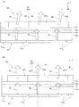
以下、図10を参照して、接続部SSの縦方向(y方向)についての形状及び構成について、第1実施形態の場合との差異を比較しつつ説明する。図10(A)は、第1実施形態との比較説明のために図3(C)を再度示すものである。図10(B)は、図10(A)の一部として、接続部SSに関する部分を抽出した概念図である。また、図10(C)は、図10(B)に対応する図であり、本実施形態における接続部SSに関する部分を抽出した概念図である。図10(B)と図10(C)との比較から明らかなように、第1実施形態と本実施形態とでは、張出し方向(厚み方向)についての最大厚さnが異なっている。具体的には、第1実施形態については、図10(B)に示すように、また、既述のように、接続部SSにおいて、接続面SSaの張出し方向(厚み方向)DSの厚さnは、0≦n≦2mmの間に維持されて変化しているものとする。すなわち、接続面SSaは、張出し方向(厚み方向)について最大厚さnmaxが、2mm以下となっており、さらに、接続部SSの全体に亘って厚さnが負の値になる(第1反射面R1と第2反射面R2との位置関係が逆転する)ことはない。これに対して、本実施形態では、図10(C)に示すように、第2反射面R2に対する第1反射面R1の張出し方向の厚さnは、接続部SSの全体に亘って−0.2≦n≦2mmで維持されている。すなわち、第1反射面R1と第2反射面R2との位置関係が逆転する箇所が存在して、nが負の値になることもあり得る。言い換えると、第1反射面R1が第2反射面R2に対して凹んでいる状態となり得る。このような状況となっている箇所が、図8や図9等に示した凹部CPを形成している。なお、nが負の値の最小値となる場合が、上述した最大差Gが0.2mmとなる場合に相当する。 Hereinafter, with reference to FIG. 10, the shape and configuration of the connection portion SS in the vertical direction (y direction) will be described while comparing the difference from the case of the first embodiment. FIG. 10A shows again FIG. 3C for comparison with the first embodiment. FIG. 10B is a conceptual diagram in which a portion related to the connection portion SS is extracted as a part of FIG. FIG. 10C is a diagram corresponding to FIG. 10B, and is a conceptual diagram in which a portion related to the connection portion SS in the present embodiment is extracted. As is clear from a comparison between FIG. 10B and FIG. 10C, the maximum thickness n in the overhang direction (thickness direction) differs between the first embodiment and the present embodiment. Specifically, in the first embodiment, as shown in FIG. 10B, and as described above, the thickness n of the connecting surface SSa in the protruding direction (thickness direction) DS in the connecting portion SS. Is maintained between 0 ≦ n ≦ 2 mm and changes. That is, the connection surface SSa has a maximum thickness n max of 2 mm or less in the overhang direction (thickness direction), and the thickness n is a negative value over the entire connection portion SS (the first value). The positional relationship between the reflecting surface R1 and the second reflecting surface R2 is not reversed). On the other hand, in the present embodiment, as shown in FIG. 10C, the thickness n in the protruding direction of the first reflecting surface R1 with respect to the second reflecting surface R2 is −0 over the entire connecting portion SS. 2 ≦ n ≦ 2 mm. That is, there may be a portion where the positional relationship between the first reflecting surface R1 and the second reflecting surface R2 is reversed, and n may be a negative value. In other words, the first reflective surface R1 can be in a state of being recessed with respect to the second reflective surface R2. A portion in such a situation forms the concave portion CP shown in FIGS. Note that the case where n is the minimum negative value corresponds to the case where the above-described maximum difference G is 0.2 mm.
以下、図11を参照して、本実施形態に係る虚像表示装置を構成する導光部材の一変形例について説明する。図11に示す変形例では、接続部SSにおいて、砂刷りまたは黒塗りされている加工面部分PS1を有している。また、第1反射面R1及び第2反射面R2に対向する反射面である第3反射面R3のうち特に、外光OLの問題を生じやすい接続部よりも映像光の入射側において、砂刷りまたは黒塗りされている加工面部分PS2を有している。上記のような箇所に砂刷りまたは黒塗りされている加工面部分PS1,PS2を有することで、外光OLを吸収または拡散させて、外光OLに起因するゴースト光の発生を抑制できる。なお、加工面部分PS1,PS2のうちどちらか一方のみを有する構成としてもよく、図示のように双方を有する構成としてもよい。 Hereinafter, with reference to FIG. 11, a modification of the light guide member constituting the virtual image display device according to the present embodiment will be described. In the modification shown in FIG. 11, the connecting portion SS has a processed surface portion PS1 that is sand-printed or black-painted. Further, among the third reflecting surface R3 which is the reflecting surface facing the first reflecting surface R1 and the second reflecting surface R2, the sand printing is performed particularly on the incident side of the image light from the connection portion that is likely to cause the problem of the external light OL. Or it has the processing surface part PS2 painted black. By having the processed surface portions PS1 and PS2 that are sand-printed or black-painted in the above-described places, it is possible to absorb or diffuse the external light OL and suppress the generation of ghost light due to the external light OL. In addition, it is good also as a structure which has only any one among process surface parts PS1 and PS2, and it is good also as a structure which has both like illustration.
以上のように、本実施形態に係る虚像表示装置では、第1反射面R1と第2反射面R2とを繋ぐ接続部SSにおいて、表面である接続面SSaの第2反射面R2に対する傾斜角度θを調整することで、外光OLの一部が反射された反射成分RLが、光路下流側に向かってしまうような場合であっても、これに起因するゴースト光の発生を抑えている。 As described above, in the virtual image display device according to this embodiment, in the connection portion SS that connects the first reflection surface R1 and the second reflection surface R2, the inclination angle θ of the connection surface SSa, which is the surface, with respect to the second reflection surface R2. Thus, even when the reflection component RL from which a part of the external light OL is reflected is directed toward the downstream side of the optical path, generation of ghost light due to this is suppressed.
また、このほか、例えば光源側からの迷光に起因するゴースト光の発生を抑制するため、必要に応じて各所に黒塗り加工を施してもよい。例えばレンズのコバ部分を黒塗り加工することで映像光に起因するゴースト光等について対処することも考えられる。 In addition to this, for example, in order to suppress generation of ghost light due to stray light from the light source side, black coating may be applied to various places as necessary. For example, it may be possible to deal with ghost light or the like caused by image light by blackening the edge of the lens.
また、上記では、第2反射面R2と第3反射面R3とを平行な平面としているが、平行な曲面で構成する場合においても、本発明を適用できる。 In the above description, the second reflecting surface R2 and the third reflecting surface R3 are parallel planes, but the present invention can also be applied to a case where the second reflecting surface R2 and the third reflecting surface R3 are configured by parallel curved surfaces.
また、上記では、第1反射面R1において、第1反射面R1が第2反射面R2よりも凹んで凹状部分TRが一部に形成されるものとなっているが(図10(C)参照)、全体に亘って凹状部分TRが形成されるものとなっていることも考えられる。 Further, in the above, in the first reflecting surface R1, the first reflecting surface R1 is recessed from the second reflecting surface R2, and the concave portion TR is partially formed (see FIG. 10C). It is also conceivable that the concave portion TR is formed over the entire surface.
〔その他〕
以上各実施形態に即して本発明を説明したが、本発明は、上記の実施形態に限られるものではなく、その要旨を逸脱しない範囲において種々の態様において実施することが可能である。例えば、上記では、画像表示装置80の光射出面である画像面OIにおいて異なる隅領域IA、OAの2点P1,P2からそれぞれ射出された映像光の光線束のうち観察者の眼に到達すべき成分が互いに交わらない位置に非軸対称非球面(レンズ面33a)が配置されているものとしているが、このような面形状を有しないものであってもよい。
[Others]
Although the present invention has been described with reference to each embodiment, the present invention is not limited to the above-described embodiment, and can be implemented in various modes without departing from the scope of the present invention. For example, in the above, image light beams emitted from two points P1 and P2 of different corner areas IA and OA on the image plane OI that is the light emission surface of the
上記の説明では、画像表示装置(映像素子)80として、OLED(有機EL)を含む画像生成部81を用いているが、これに限らず、画像表示装置80として、透過型の液晶表示デバイスとバックライトとで構成されるもの等種々のものを利用可能である。
In the above description, the
また、例えば、反射型の液晶表示デバイスを用いた構成も可能であり、液晶表示デバイス等からなる画像生成部81に代えてデジタル・マイクロミラー・デバイス等を用いることもできる。また、自発光型素子として、LEDアレイ等を用いることもできる。
Further, for example, a configuration using a reflective liquid crystal display device is possible, and a digital micromirror device or the like can be used instead of the
また、上記実施形態では、OLED(有機EL)を含むパネル型の画像表示装置80を用いているが、これに代えて走査型の画像表示装置を用いることもできる。具体的には、例えば画像面OIに光拡散素子を配置し、走査型の照明光学系によって画像面OIの位置において光を走査させ画像を形成させるとともに当該光拡散素子の拡散作用によって、映像光を射出させることで、上記と同様の構成を適用させることができる。
Moreover, in the said embodiment, although the panel type
また、上記実施形態では、左右の導光装置20をそれぞれ個別に作製されるものであるが、これに限らず、例えば、光透過部材を共有する構成とすることもできる。図12(A)及び12(B)は、導光装置の一変形例について説明するための概念図である。この例では、左右一対の導光部材10,10と光透過部材150とは、左右一対の導光部材10,10により1つの光透過部材150を挟んで接続して一体の光学部材となって左右が一体化した導光装置20として機能している。この場合、両眼視のための位置合わせを光透過部材150により簡易かつ正確に行うことができる。例えば図12(A)に示すように、光透過部材150の中心部CEを適度に曲げておくことで、左右の角度を規定することも可能である。また、例えば図12(B)に示すように、中心部CEにおいて、上下の端部に窪み部CVa,CVbを設けておくことで、窪み部CVa,CVbを、製造工程において光透過部材150に対する導光部材10,10の接着固定のための位置決め(位置固定)に利用したり、鼻受部を設けるための箇所として用いたりすることが可能である。
Moreover, in the said embodiment, although the left and right
上記の説明では、導光装置20について、光入射部(第2導光部分12)から光射出部(第1導光部分11)を一部材で構成されるものとしているが、このような構成以外にも、例えば光反射膜RM(図2参照)で構成されるような光反射面を経ることなく映像光GLを全反射による導光部分に直接入射させたり、導光装置20の導光部材10をプリズム等で構成される光入射部と導光部とに分離した構成としたりするものとしてもよい。
In the above description, the
上記の説明では、投射光学系として複数のレンズで構成される投射レンズ30を採用しているが、これに限らず、例えば図13に示すように、プリズム状の部材である投射プリズム光学系230によって投射光学系を構成するものとしてもよい。この場合においても、例えば、投射プリズム光学系230において光路変更に寄与する各面231a〜233aのうち、画像表示装置80からそれぞれ射出された映像光の光線束のうち、観察者の眼に到達すべき成分である部分光線束GLa,GLbが互いに交わらない位置に配置されている光入射面233aを非軸対称非球面(自由曲面)とすることで、適切な収差補正が可能になる。なお、光入射面233a以外の面である反射面232aや光射出面231aについても非軸対称非球面(自由曲面)としてもよい。さらに、図示では、投射光学系である投射プリズム光学系230と導光装置20(導光部材10)とが接続されておらず別体となっているが、これらが接続されて一体になっている構成とすることも可能である。ここでは、例えば投射プリズム光学系230の後段に上記と同様に各部分光線束に対応した非線形性の形状を有し、また、配置される絞りSTを設けることで、適切な遮光の処理を行うことができる。
In the above description, the
上記のうち、図6(B)等において、一変形例として斜めに配置する絞りSTについて説明しているが、斜めに配置するにあたっての配置のしかたや開口部OPの形状については、上記の他にも、種々の態様が可能である。例えば図6(B)等に示した場合とは傾ける方向を逆にしてもよい。絞りSTの配置や形状については、光線束の形状や取り込むべき光の違い等種々の状況に応じて最適なものとすることができる。例えば、開口部OPの形状について水平方向に関して左右どちらを大きくするか等適宜変更可能である。 Among the above, in FIG. 6B and the like, the diaphragm ST disposed obliquely is described as a modified example. However, the arrangement and the shape of the opening OP when disposed obliquely are other than those described above. In addition, various modes are possible. For example, the tilting direction may be reversed from the case shown in FIG. The arrangement and shape of the aperture stop ST can be optimized according to various situations such as the shape of the light beam and the difference in light to be captured. For example, the shape of the opening OP can be changed as appropriate, such as which of the left and right in the horizontal direction is increased.
上記の説明では、ハーフミラー層(半透過反射膜)15が横長の矩形領域に形成されるとしたが、ハーフミラー層15の輪郭は用途その他の仕様に応じて適宜変更することができる。また、ハーフミラー層15の透過率や反射率も用途その他に応じて変更することができる。
In the above description, the half mirror layer (semi-transmissive reflective film) 15 is formed in a horizontally long rectangular region. However, the contour of the
上記の説明では、一対の表示装置100A,100Bを備える虚像表示装置100について説明しているが、単一の表示装置とできる。つまり、右眼及び左眼の双方に対応して、一組ずつ投射透視装置70及び画像表示装置80を設けるのではなく、右眼又は左眼のいずれか一方に対してのみ投射透視装置70及び画像表示装置80を設け、画像を片眼視する構成にしてもよい。
In the above description, the virtual
上記の説明では、ハーフミラー層15が単なる半透過性の膜(誘電体多層膜)であるとしたが、ハーフミラー層15は、平面又は曲面のホログラム素子に置き換えることができる。また、この他、ハーフミラー層15に代えて、曲面上に複数の微細な反射面を並べたり、フレネルミラーを用いたり、他の回折素子を用いたりすることもできる。
In the above description, the
上記の説明では、導光部材10等が眼EYの並ぶ横方向に延びているが、導光部材10を縦方向に延びるように配置することもできる。この場合、導光部材10は、直列的ではなく並列的に平行配置された構造を有することになる。
In the above description, the
また、接続部SSの箇所も反射面の反射回数等や、それに伴う反射面の個数に応じて種々の箇所に設けることが可能であり、複数箇所に上記した形状、構造を有する接続部SSが設けられるものとしてもよい。 In addition, the connection portion SS can be provided at various locations according to the number of reflections of the reflection surface and the like, and the number of reflection surfaces associated therewith. The connection portion SS having the shape and structure described above is provided at a plurality of locations. It may be provided.
また、上記各実施形態では、例えば図14に概念的に示すように、導光装置20における導光部材10での映像光GLの導光に際して、映像光GLのうち接続部SS付近を通過する成分の第1反射面R1(第4面S14)での反射位置AR1から当該成分の中間像の位置(結像位置)AR2を離間させている(図示の場合、第4面S14や第1面S11と対向する第3面S13側において中間像を形成(結像)させている。)。言い換えると、接続部SS付近で反射する映像光GLの中間像の位置AR2を接続部SSから離して、接続部SS付近にある反射位置AR1及びその周辺を通過するときの映像光GLをぼけた状態にさせている。これにより、映像光GLが接続部SS付近を通過する際に、もしも、接続部SS付近での外光の反射や散乱等により意図しない成分が多少入り込んで導光部材10において導光されることがあったとしても、これによるゴースト光発生等の影響を抑制できるものとなる。具体的に説明すると、反射位置AR1から中間像の位置AR2を離間させておくことで、例えば上記のような意図しない成分が入ったとしても、当該成分について観察者の眼に対して映像光GLが導光され射出される光路の範囲から離れた位置で導光させ射出させることができ、侵入した外光が見えづらくなるようにできる。また、接続部SS付近を通過するときには映像光GLがぼけた状態にあることで、観察者の眼の位置において複雑な凹凸形状を有する接続部SSにピントが合わないようにでき、接続部SSの形状が視認されることを防止できる。上記の場合とは逆に、仮に中間像の位置AR2を接続部SS付近に近づけた構成としてしまうと、映像光GLに意図しないで入り込んだ外光に起因する成分による影響を受け易くなってしまう可能性が高まると考えられる。これに対して、上記のように、各実施形態では、第1反射面R1(第4面S14)で反射される映像光GLのうち少なくとも接続部SS付近で反射される成分の反射位置AR1を中間像の位置AR2から離間させておくことで、かかる事態を回避することができるようになっている。
In each of the above embodiments, for example, conceptually shown in FIG. 14, when the video light GL is guided by the
また、虚像表示装置の外観構成についても、種々の態様が可能であり、例えば、図15に示すような外観形状の虚像表示装置200において、本願発明を適用することも可能である。なお、図示の虚像表示装置200を構成する各部について、図1に示す虚像表示装置100と同一の符号で示すものは、その機能構成が同等であるため、説明を省略する。すなわち、虚像表示装置200における導光部材10,10に関して、上述した各実施形態のような構成のものを組み込むことが可能である。
Moreover, various aspects are possible also about the external appearance structure of a virtual image display apparatus, for example, it is also possible to apply this invention in the virtual
また、例えば、平行な平板状の導光部材に投射プリズム(プリズム状の投射光学系)を接着して光学系を構成する場合のように、2部品(又は2部品以上)の部材を接合させる接続部(接合部)に関して、本願のような外光への対応がなされた構造とするものとしてもよい。 Further, for example, as in the case where an optical system is configured by bonding a projection prism (prism-shaped projection optical system) to a parallel flat light guide member, members of two parts (or two or more parts) are joined. The connection part (joint part) may have a structure adapted to external light as in the present application.
AP…矢印、 C1…交点、 C2…交点、 CC…接着層、 CE…中心部、 CF…カラーフィルター層、 CFr,CFg,CFb…色用カラーフィルター部、 CS…交点、 CVa,CVb…窪み部部、 DD1…第1方向、 DD2…第2方向、 DS…張出し方向(厚み方向)、 DX…導光軸、 ER1…領域部分、 ER2…領域部分、 EY…眼想定位置(眼)、 GL…映像光、 GLa,GLb…部分光線束、 HL…外界光、 IA,OA…隅領域、 LX…レンズ光軸、 OI…画像面、 OL…外光、 OP…開口部、 P1,P2…点、 PF1…延長面、 R1…第1反射面(S14…第4面)、 R2…第2反射面(S11…第1面)、 R3…第3反射面(S13…第3面)、 RL…反射成分、 RM…光反射膜、 S11−S15…面、 S51−S53…透過面、 SF1…第1表面、 SF2…第2表面、 SS…接続部、 SSa…接続面(傾斜接続面)、 SX…視線軸、 XX1…第1軸、 XX2…第2軸、 31−33…レンズ(光学素子)、 10…導光部材、 10s…本体、 11…導光部分(光射出部)、 12…導光部分(光入射部)、 15…ハーフミラー層(半透過反射部、 20…導光装置、 27…ハードコート層、 30…投射レンズ(投射光学系)、 31a…レンズ面、 33a…レンズ面、 39…鏡筒、 40…鼻受部、 50…光透過部材、 70…投射透視装置、 71a,71a,71a…透明電極、 72a…対向電極、 73a…有機EL層(発光層)、 74a…保護層、 80…画像表示装置(映像素子)、 81…画像生成部、 82…配光制御部、 100…虚像表示装置、 100A,100B…表示装置、 101a,101b…光学部材、 102…枠部、 105a,105b…像形成本体部、 150…光透過部材、 230…投射プリズム光学系(投射光学系)、 231a…光射出面、 232a…反射面、 233a…光入射面 A1,A2,AS…領域、 CP…凹部、 G…最大差、 PP…中心、 PS1,PS2…加工面部分、 TR…凹状部分、 W…幅、 n1…屈折率、 α0…入射角、 α1…屈折角、 α2…角度、 θ…傾斜角度(最大傾斜角度)、 200…虚像表示装置
AP ... arrow, C1 ... intersection, C2 ... intersection, CC ... adhesive layer, CE ... center part, CF ... color filter layer, CFr, CFg, CFb ... color filter part for color, CS ... intersection, CVa, CVb ... recessed part Part, DD1 ... first direction, DD2 ... second direction, DS ... extension direction (thickness direction), DX ... light guide axis, ER1 ... region portion, ER2 ... region portion, EY ... predicted eye position (eye), GL ... Image light, GLa, GLb ... Partial beam, HL ... External light, IA, OA ... Corner area, LX ... Lens optical axis, OI ... Image plane, OL ... Outside light, OP ... Opening, P1, P2 ... Point, PF1 ... extension surface, R1 ... first reflection surface (S14 ... fourth surface), R2 ... second reflection surface (S11 ... first surface), R3 ... third reflection surface (S13 ... third surface), RL ... reflection Component, RM: Light reflecting film, S11-S15: Surface, S 1-S53 ... transmission surface, SF1 ... first surface, SF2 ... second surface, SS ... connection portion, SSa ... connection surface (inclined connection surface), SX ... line of sight, XX1 ... first axis, XX2 ... second axis 31-33 ... lens (optical element), 10 ... light guide member, 10s ... main body, 11 ... light guide part (light emitting part), 12 ... light guide part (light incident part), 15 ... half mirror layer (half) Transmitting / reflecting part, 20 ... light guide device, 27 ... hard coat layer, 30 ... projection lens (projection optical system), 31a ... lens surface, 33a ... lens surface, 39 ... lens barrel, 40 ... nose receiving part, 50 ... light Transmissive member, 70 ... projection fluoroscopic device, 71a, 71a, 71a ... transparent electrode, 72a ... counter electrode, 73a ... organic EL layer (light emitting layer), 74a ... protective layer, 80 ... image display device (video element), 81 ...
Claims (20)
複数の反射面を有して内面で反射させることにより前記映像素子からの映像光を導光するとともに、映像光と外界光とを重複して視認させる導光部材と
を備え、
前記導光部材は、前記複数の反射面のうち外界光の入射側と反対側に配置されかつ隣り合う反射面として、第1反射面と、前記第1反射面よりも映像光の射出側に位置する第2反射面とを有し、前記第1反射面と前記第2反射面とを繋ぐ接続部において、前記第1反射面を前記第2反射面以上に張り出させている、虚像表示装置。 An image element for generating image light;
A light guide member that has a plurality of reflection surfaces and guides the image light from the image element by being reflected by the inner surface, and makes the image light and the external light visible in an overlapping manner,
The light guide member is disposed on the opposite side to the outside light incident side of the plurality of reflection surfaces and is adjacent to the first reflection surface, and on the image light emission side from the first reflection surface. A virtual image display having a second reflecting surface positioned and projecting the first reflecting surface beyond the second reflecting surface at a connection portion connecting the first reflecting surface and the second reflecting surface. apparatus.
前記第2反射面は、平坦面である、請求項1に記載の虚像表示装置。 The first reflecting surface is a free-form surface;
The virtual image display device according to claim 1, wherein the second reflecting surface is a flat surface.
複数の反射面を有して内面で反射させることにより前記映像素子からの映像光を導光するとともに、映像光と外界光とを重複して視認させる導光部材と
を備え、
前記導光部材は、前記複数の反射面のうち外界光の入射側と反対側に配置されかつ隣り合う反射面として、第1反射面と、前記第1反射面よりも映像光の射出側に位置する第2反射面とを有するとともに、前記第1反射面と前記第2反射面とを繋ぐ接続部を有し、
前記接続部は、前記第1反射面が前記第2反射面よりも凹んで凹状部分を形成する箇所において、前記凹状部分に応じて前記第2反射面に対して所定値以下の傾斜角度を保持する傾斜接続面を形成する、虚像表示装置。 An image element for generating image light;
A light guide member that has a plurality of reflection surfaces and guides the image light from the image element by being reflected by the inner surface, and makes the image light and the external light visible in an overlapping manner,
The light guide member is disposed on the opposite side to the outside light incident side of the plurality of reflection surfaces and is adjacent to the first reflection surface, and on the image light emission side from the first reflection surface. Having a second reflection surface located, and having a connecting portion connecting the first reflection surface and the second reflection surface,
The connection portion maintains an inclination angle equal to or less than a predetermined value with respect to the second reflection surface according to the concave portion at a location where the first reflection surface is recessed from the second reflection surface to form a concave portion. A virtual image display device that forms an inclined connection surface.

前記導光部材を構成する前記複数の反射面のうち第1面と第3面とは、対向するように配置され、前記第1面と前記第3面とを通過させて外界を視認した時に、視度が略0になっており、
前記映像素子からの映像光は、前記第3面で全反射され、前記第1面で全反射され、第2面で反射された後、前記第1面を透過して、観察側に到達する、請求項1から13までのいずれか一項に記載の虚像表示装置。 The light guide member includes two or more non-axisymmetric curved surfaces,
The first surface and the third surface of the plurality of reflecting surfaces constituting the light guide member are arranged to face each other, and when the outside is visually recognized through the first surface and the third surface. The diopter is almost 0,
The image light from the image element is totally reflected by the third surface, totally reflected by the first surface, reflected by the second surface, and then passes through the first surface to reach the observation side. The virtual image display device according to any one of claims 1 to 13.
前記第1反射面は、前記第4面であり、
前記第2反射面は、前記第1面である、請求項14に記載の虚像表示装置。 The light guide member includes a fourth surface that is adjacent to the first surface and reflects video light to be incident on the third surface;
The first reflective surface is the fourth surface;
The virtual image display device according to claim 14, wherein the second reflection surface is the first surface.
前記投射光学系は、前記映像素子の中心を通り前記法線方向に平行な投射光学系光軸に対して垂直に配置され、かつ、前記第1方向に平行に延びて前記投射光学系光軸に交差する第1軸について線対称で前記第2方向に平行に延びて前記投射光学系光軸に交差する第2軸について非線対称な四角形状の開口部、または、前記投射光学系光軸に対して非垂直に配置されている四角形状の開口部を形成する絞りを有する、請求項16及び17のいずれか一項に記載の虚像表示装置。 A direction perpendicular to the normal direction of the light emitting surface of the image element and corresponding to the light guide direction of the light guide member is defined as a first direction, and the normal direction and the first direction are defined as the first direction. When the vertical direction is the second direction,
The projection optical system is disposed perpendicular to the optical axis of the projection optical system that passes through the center of the image element and is parallel to the normal line direction, and extends in parallel with the first direction so that the optical axis of the projection optical system A quadrangular opening that is axisymmetric about a first axis that intersects the optical axis and extends parallel to the second direction and is axisymmetric about a second axis that intersects the optical axis of the projection optical system, or the optical axis of the projection optical system The virtual image display device according to any one of claims 16 and 17, further comprising a diaphragm that forms a square-shaped opening that is arranged non-perpendicular to the vertical direction.
Priority Applications (1)
| Application Number | Priority Date | Filing Date | Title |
|---|---|---|---|
| US15/381,859 US10261322B2 (en) | 2015-12-25 | 2016-12-16 | Virtual image display apparatus |
Applications Claiming Priority (2)
| Application Number | Priority Date | Filing Date | Title |
|---|---|---|---|
| JP2015253153 | 2015-12-25 | ||
| JP2015253153 | 2015-12-25 |
Publications (2)
| Publication Number | Publication Date |
|---|---|
| JP2017120384A true JP2017120384A (en) | 2017-07-06 |
| JP6819221B2 JP6819221B2 (en) | 2021-01-27 |
Family
ID=59272239
Family Applications (1)
| Application Number | Title | Priority Date | Filing Date |
|---|---|---|---|
| JP2016212637A Active JP6819221B2 (en) | 2015-12-25 | 2016-10-31 | Virtual image display device |
Country Status (1)
| Country | Link |
|---|---|
| JP (1) | JP6819221B2 (en) |
Cited By (5)
| Publication number | Priority date | Publication date | Assignee | Title |
|---|---|---|---|---|
| JP2021507277A (en) * | 2017-12-20 | 2021-02-22 | ビュージックス コーポレーションVuzix Corporation | Augmented reality display system |
| CN113970849A (en) * | 2020-07-22 | 2022-01-25 | 株式会社理光 | Transmission optical system, virtual image display device, and head-mounted display |
| CN114690432A (en) * | 2022-06-02 | 2022-07-01 | 舜宇光学(浙江)研究院有限公司 | Offset display optical machine and method thereof and near-to-eye display equipment |
| JP2023001126A (en) * | 2018-05-31 | 2023-01-04 | 中強光電股▲ふん▼有限公司 | Head-mounted display device |
| US11550154B2 (en) | 2019-10-30 | 2023-01-10 | Seiko Epson Corporation | Virtual image display device and light-guiding member |
-
2016
- 2016-10-31 JP JP2016212637A patent/JP6819221B2/en active Active
Cited By (10)
| Publication number | Priority date | Publication date | Assignee | Title |
|---|---|---|---|---|
| JP2021507277A (en) * | 2017-12-20 | 2021-02-22 | ビュージックス コーポレーションVuzix Corporation | Augmented reality display system |
| JP7171727B2 (en) | 2017-12-20 | 2022-11-15 | ビュージックス コーポレーション | Augmented reality display system |
| JP2022188158A (en) * | 2017-12-20 | 2022-12-20 | ビュージックス コーポレーション | Augmented reality display system |
| US11921289B2 (en) | 2017-12-20 | 2024-03-05 | Vuzix Corporation | Augmented reality display system |
| JP7526239B2 (en) | 2017-12-20 | 2024-07-31 | ビュージックス コーポレーション | Augmented Reality Display System |
| JP2023001126A (en) * | 2018-05-31 | 2023-01-04 | 中強光電股▲ふん▼有限公司 | Head-mounted display device |
| JP7406612B2 (en) | 2018-05-31 | 2023-12-27 | 中強光電股▲ふん▼有限公司 | head mounted display device |
| US11550154B2 (en) | 2019-10-30 | 2023-01-10 | Seiko Epson Corporation | Virtual image display device and light-guiding member |
| CN113970849A (en) * | 2020-07-22 | 2022-01-25 | 株式会社理光 | Transmission optical system, virtual image display device, and head-mounted display |
| CN114690432A (en) * | 2022-06-02 | 2022-07-01 | 舜宇光学(浙江)研究院有限公司 | Offset display optical machine and method thereof and near-to-eye display equipment |
Also Published As
| Publication number | Publication date |
|---|---|
| JP6819221B2 (en) | 2021-01-27 |
Similar Documents
| Publication | Publication Date | Title |
|---|---|---|
| JP6641987B2 (en) | Virtual image display | |
| CN106896501B (en) | Virtual image display device | |
| JP6019918B2 (en) | Virtual image display device | |
| JP6065630B2 (en) | Virtual image display device | |
| KR101801099B1 (en) | Virtual image display apparatus | |
| JP6065631B2 (en) | Virtual image display device | |
| JP6221732B2 (en) | Virtual image display device | |
| JP6582481B2 (en) | Virtual image display device | |
| JP6163791B2 (en) | Virtual image display device | |
| JP6111636B2 (en) | Virtual image display device | |
| JP6819221B2 (en) | Virtual image display device | |
| US10261322B2 (en) | Virtual image display apparatus | |
| US20190265479A1 (en) | Virtual image display device | |
| US11099395B2 (en) | Virtual image display device | |
| CN112748572B (en) | Virtual image display device and light guide member | |
| JP6380620B2 (en) | Virtual image display device | |
| US20220276493A1 (en) | Optical module and head-mounted display device | |
| US20220137412A1 (en) | Virtual image display device and optical unit | |
| US20230280592A1 (en) | Light guide member and display device | |
| CN114578558B (en) | Optical module and display device | |
| US12025804B2 (en) | Virtual image display device and optical unit | |
| US20220137406A1 (en) | Virtual image display device and optical unit |
Legal Events
| Date | Code | Title | Description |
|---|---|---|---|
| A80 | Written request to apply exceptions to lack of novelty of invention |
Free format text: JAPANESE INTERMEDIATE CODE: A80 Effective date: 20161124 |
|
| RD05 | Notification of revocation of power of attorney |
Free format text: JAPANESE INTERMEDIATE CODE: A7425 Effective date: 20180906 |
|
| RD03 | Notification of appointment of power of attorney |
Free format text: JAPANESE INTERMEDIATE CODE: A7423 Effective date: 20181116 |
|
| A621 | Written request for application examination |
Free format text: JAPANESE INTERMEDIATE CODE: A621 Effective date: 20190827 |
|
| A977 | Report on retrieval |
Free format text: JAPANESE INTERMEDIATE CODE: A971007 Effective date: 20200630 |
|
| A131 | Notification of reasons for refusal |
Free format text: JAPANESE INTERMEDIATE CODE: A131 Effective date: 20200728 |
|
| RD07 | Notification of extinguishment of power of attorney |
Free format text: JAPANESE INTERMEDIATE CODE: A7427 Effective date: 20200803 |
|
| A521 | Written amendment |
Free format text: JAPANESE INTERMEDIATE CODE: A523 Effective date: 20200924 |
|
| TRDD | Decision of grant or rejection written | ||
| A01 | Written decision to grant a patent or to grant a registration (utility model) |
Free format text: JAPANESE INTERMEDIATE CODE: A01 Effective date: 20201201 |
|
| A61 | First payment of annual fees (during grant procedure) |
Free format text: JAPANESE INTERMEDIATE CODE: A61 Effective date: 20201214 |
|
| R150 | Certificate of patent or registration of utility model |
Ref document number: 6819221 Country of ref document: JP Free format text: JAPANESE INTERMEDIATE CODE: R150 |