JP2017120302A - Display device, display system, control method of display device, and program - Google Patents

Display device, display system, control method of display device, and program Download PDF

Info

Publication number
JP2017120302A
JP2017120302A JP2015256140A JP2015256140A JP2017120302A JP 2017120302 A JP2017120302 A JP 2017120302A JP 2015256140 A JP2015256140 A JP 2015256140A JP 2015256140 A JP2015256140 A JP 2015256140A JP 2017120302 A JP2017120302 A JP 2017120302A
Authority
JP
Japan
Prior art keywords
unit
display
image
display unit
user
Prior art date
Legal status (The legal status is an assumption and is not a legal conclusion. Google has not performed a legal analysis and makes no representation as to the accuracy of the status listed.)
Granted
Application number
JP2015256140A
Other languages
Japanese (ja)
Other versions
JP6740613B2 (en
Inventor
小嶋 輝人
Teruhito Kojima
輝人 小嶋
高野 正秀
Masahide Takano
正秀 高野
Current Assignee (The listed assignees may be inaccurate. Google has not performed a legal analysis and makes no representation or warranty as to the accuracy of the list.)
Seiko Epson Corp
Original Assignee
Seiko Epson Corp
Priority date (The priority date is an assumption and is not a legal conclusion. Google has not performed a legal analysis and makes no representation as to the accuracy of the date listed.)
Filing date
Publication date
Application filed by Seiko Epson Corp filed Critical Seiko Epson Corp
Priority to JP2015256140A priority Critical patent/JP6740613B2/en
Priority to US15/372,079 priority patent/US10133407B2/en
Publication of JP2017120302A publication Critical patent/JP2017120302A/en
Application granted granted Critical
Publication of JP6740613B2 publication Critical patent/JP6740613B2/en
Active legal-status Critical Current
Anticipated expiration legal-status Critical

Links

Images

Abstract

PROBLEM TO BE SOLVED: To enable a user wearing a head-mounted display device to easily perform operation of the display device.SOLUTION: An HMD 100 comprises a right light guide part 26 and a left light guide part 28 as display parts that display an image so as to enable a user to visually recognize a real object while being attached to the head of the user. The HMD 100 includes a right sensor part 410 and a left sensor part 420 that detect approach of an indication body to the right light guide part 26 and left light guide part 28, and touch pads 401 and 402 that receive operation. The HMD 100 includes a control part that associates display of the right light guide part 26 and left light guide part 28 with operation corresponding to a movement of the indication body according to the movement of the indication body detected by the right sensor part 410 and left sensor part 420.SELECTED DRAWING: Figure 1

Description

本発明は、表示装置、表示システム、表示装置の制御方法、及び、プログラムに関する。   The present invention relates to a display device, a display system, a display device control method, and a program.

従来、頭部装着型の表示装置であるヘッドマウントディスプレイ(Head Mounted Display:HMD)が知られている(例えば、特許文献1参照)。特許文献1には、ユーザーの眼前に装着され、ユーザーを、現実世界からの干渉を受けることなく仮想世界の画像に没入させる。   Conventionally, a head mounted display (HMD), which is a head-mounted display device, is known (see, for example, Patent Document 1). Japanese Patent Application Laid-Open No. 2004-151561 is worn in front of the user's eyes and immerses the user in the image of the virtual world without receiving interference from the real world.

特開2015−118332号公報JP-A-2015-118332

ところで、HMDの中には、現実世界の実空間を視認できる構成を有するものもある。この種のHMDの用途として、例えば、実空間の対象に対する作業を支援する目的で使用されるHMDは、テキストや画像を表示する用途がある。このような場合に、使用者がHMDを操作するために、コントローラーのスイッチを触る動作を行うことは、操作を行う手を空ける必要があり、面倒である。また、特許文献1に記載されたように使用者の眼前に配置されるタッチセンサーに触る動作も、操作を行う手を空ける必要があり、面倒である。さらに、特許文献1に記載されたタッチセンサーは眼前のスペースに配設されており、現実世界の実空間を視認できる構成のHMDに適用することはできない。
本発明は上記事情に鑑みてなされたものであり、頭部装着型の表示装置を装着する使用者が、容易に、表示装置に対する操作を行えるようにすることを目的とする。
By the way, some HMDs have a configuration capable of visually recognizing real space in the real world. As an application of this type of HMD, for example, the HMD used for the purpose of supporting work on a real space object has an application of displaying text and images. In such a case, in order for the user to operate the HMD, it is troublesome to perform an operation of touching the switch of the controller because it is necessary to release the hand for performing the operation. Further, as described in Patent Document 1, the operation of touching the touch sensor disposed in front of the user's eyes also requires troublesome operation and is troublesome. Furthermore, the touch sensor described in Patent Document 1 is disposed in a space in front of the eyes, and cannot be applied to an HMD configured to visually recognize a real space in the real world.
The present invention has been made in view of the above circumstances, and an object of the present invention is to enable a user wearing a head-mounted display device to easily operate the display device.

上記目的を達成するために、使用者の頭部に装着された状態で、前記使用者が実物体を視認可能に画像を表示する表示部と、前記表示部周辺への指示体の接近を検出する検出部と、操作を受け付ける操作部と、前記検出部により検出される前記指示体の動きにより、前記表示部における表示と前記指示体の動きに対応する操作とを対応させる制御部と、を備えることを特徴とする。
本発明によれば、表示部に指示体を接近させることにより、表示部に接触することなく容易に表示装置を操作でき、例えば作業中に操作を行う場合等の利便性の向上を図ることができる。
In order to achieve the above-described object, the display unit displays an image so that the user can visually recognize the real object while being attached to the user's head, and the approach of the indicator to the periphery of the display unit is detected. A detection unit that receives the operation, and a control unit that associates the display on the display unit with the operation corresponding to the movement of the indicator by the movement of the indicator detected by the detection unit. It is characterized by providing.
According to the present invention, by bringing the indicator close to the display unit, the display device can be easily operated without touching the display unit. For example, it is possible to improve convenience when performing an operation during work. it can.

また、本発明は、上記表示装置において、前記制御部は、前記操作部により受け付けられた操作に対応して処理を行う通常動作モードと、前記検出部の検出結果に応じて前記表示部の表示を伴う処理を実行する近接操作モードと、を切り替えて実行すること、を特徴とする。
本発明によれば、表示部に対する接近による操作を行う近接操作モードと通常動作モードとを切り替えることで、誤操作を防止できる。
Further, according to the present invention, in the display device, the control unit displays the display unit according to a normal operation mode in which processing is performed in response to an operation received by the operation unit, and a detection result of the detection unit. It is characterized by switching and executing the proximity operation mode for executing the process involving the.
According to the present invention, erroneous operation can be prevented by switching between a proximity operation mode in which an operation is performed by approaching the display unit and a normal operation mode.

また、本発明は、上記表示装置において、前記制御部は、操作用のメニュー画面を前記表示部に表示させ、前記通常動作モードでは前記操作部により受け付ける操作を前記メニュー画面の選択または確定の操作として処理し、前記近接操作モードでは前記検出部が検出する物体の接近または離隔に対応して前記メニュー画面の選択または確定の処理を行うこと、を特徴とする。
本発明によれば、メニュー画面を利用して、通常動作モード及び近接操作モードのいずれにおいても、簡単に表示装置を操作することが可能となる。
Further, according to the present invention, in the display device, the control unit displays an operation menu screen on the display unit, and an operation accepted by the operation unit in the normal operation mode is an operation for selecting or confirming the menu screen. In the proximity operation mode, the menu screen is selected or confirmed in accordance with the approach or separation of the object detected by the detection unit.
According to the present invention, it is possible to easily operate the display device using the menu screen in both the normal operation mode and the proximity operation mode.

また、本発明は、上記表示装置において、前記表示部は、前記使用者の頭部に装着された状態で前記使用者の左眼側に位置する左眼用表示部、及び、右眼側に位置する右眼用表示部を備え、前記検出部が検出する前記左眼用表示部に対する操作と前記右眼用表示部に対する操作との組み合わせに対応付けて、前記制御部が実行する処理が設定されること、を特徴とする。
本発明によれば、表示装置の右側と左側のそれぞれに対する操作の組合せに応じた処理を実行するので、誤操作のおそれが小さいため、高度で複雑な処理を近接操作に割り当てることができる。これにより、より容易に表示装置を操作できる。
Further, according to the present invention, in the above display device, the display unit is mounted on the user's head, the display unit for the left eye located on the left eye side of the user, and the right eye side. A process executed by the control unit is set in association with a combination of an operation on the left-eye display unit and an operation on the right-eye display unit detected by the detection unit. It is characterized by that.
According to the present invention, since processing according to a combination of operations on the right side and the left side of the display device is executed, there is little risk of erroneous operation, so advanced and complicated processing can be assigned to proximity operations. Thereby, a display apparatus can be operated more easily.

また、本発明は、上記表示装置において、前記制御部は、前記検出部が検出する操作に係る情報を含む案内画面を前記表示部によって表示し、前記案内画面の左半分に表示される情報は前記左眼用表示部の左側部分に対する操作に対応し、前記案内画面の右半分に表示される情報は前記右眼用表示部の右側部分に対する操作に対応すること、を特徴とする。
本発明によれば、使用者の頭部に装着される表示部の形状を利用して、使用者が案内画面を見ながら直感的に操作を行うことができる。
Further, in the display device according to the present invention, the control unit displays a guidance screen including information related to an operation detected by the detection unit by the display unit, and information displayed on a left half of the guidance screen is The information corresponding to the operation on the left side of the display unit for the left eye corresponds to the operation on the right side of the display unit for the right eye.
ADVANTAGE OF THE INVENTION According to this invention, a user can operate intuitively, looking at a guidance screen using the shape of the display part with which a user's head is mounted | worn.

また、本発明は、上記表示装置において、前記制御部は、前記表示部によって前記使用者の右眼と左眼との両方に視認可能な態様で操作用画面を表示し、前記左眼用表示部の左側部分に対する操作に対応して前記操作用画面の左半分の表示を変更し、前記右眼用表示部の右側部分に対する操作に対応して前記操作用画面の右半分の表示を変更すること、を特徴とする。
本発明によれば、使用者の頭部に装着される表示部の形状を利用して、使用者の感覚に適する態様で表示を変更できる。
Further, in the display device according to the present invention, the control unit displays an operation screen in a manner that is visible to both the right eye and the left eye of the user by the display unit, and the display for the left eye The left half display of the operation screen is changed corresponding to the operation on the left side portion of the unit, and the right half display of the operation screen is changed corresponding to the operation on the right side portion of the right eye display unit It is characterized by this.
ADVANTAGE OF THE INVENTION According to this invention, a display can be changed in the aspect suitable for a user's sense using the shape of the display part with which a user's head is mounted | worn.

また、本発明は、上記表示装置において、前記検出部は、前記左眼用表示部に対する物体の接近、及び、前記右眼用表示部に対する物体の接近を検出すること、を特徴とする。
本発明によれば、使用者が、表示部に接触することなく容易に表示装置を操作できる。
In the display device according to the present invention, the detection unit detects an approach of an object to the left-eye display unit and an approach of an object to the right-eye display unit.
According to the present invention, the user can easily operate the display device without touching the display unit.

また、本発明は、上記表示装置において、前記制御部は、前記検出部によって検出される前記使用者の頭を基準として上下方向に物体が移動する動作、左右方向に物体が移動する操作、及び、前記表示部に対し物体が接近及び離隔する操作に対応して、前記表示部の表示を変更すること、を特徴とする。
本発明によれば、物体を表示部に接近及び離隔させる操作と、上下や左右に移動させる操作とを検出するので、より容易に、表示装置に対する多彩な操作を行うことができる。
Further, in the display device according to the present invention, the control unit includes an operation in which an object moves in the vertical direction with respect to the user's head detected by the detection unit, an operation in which the object moves in the horizontal direction, and The display of the display unit is changed in response to an operation in which the object approaches and separates from the display unit.
According to the present invention, since an operation for moving an object closer to and away from the display unit and an operation for moving the object up and down or left and right are detected, various operations on the display device can be performed more easily.

また、本発明は、上記表示装置において、前記制御部は、前記検出部によって、前記右眼用表示部及び前記左眼用表示部の両方において前記使用者の頭を基準として上下方向または左右方向に物体が移動する操作を検出した場合に、前記表示部の表示領域における上下方向または左右方向の位置入力を受け付けること、を特徴とする。
本発明によれば、物体を表示部に接近させて移動させる操作によって位置入力を行うことができ、より容易に表示装置を操作できる。
In the display device according to the aspect of the invention, the control unit may cause the detection unit to perform vertical and horizontal directions with respect to the user's head in both the right-eye display unit and the left-eye display unit. When an operation of moving an object is detected, a position input in the vertical direction or the horizontal direction in the display area of the display unit is received.
According to the present invention, position input can be performed by an operation of moving an object close to the display unit, and the display device can be operated more easily.

また、本発明は、上記表示装置において、前記制御部は、前記検出部によって検出される2以上の位置における操作に対応して、検出された操作位置とは異なる位置に対応する入力を受け付けること、を特徴とする。
本発明によれば、位置入力を行う場合に、入力する位置と操作位置との対応に関する制約を緩和し、より容易に表示装置を操作できる。
According to the present invention, in the display device, the control unit accepts an input corresponding to a position different from the detected operation position in response to an operation at two or more positions detected by the detection unit. It is characterized by.
According to the present invention, when position input is performed, restrictions on correspondence between the input position and the operation position can be relaxed, and the display device can be operated more easily.

上記表示装置において、前記検出部は、前記表示部の外表面への接触、及び、前記表示部の外側からの物体の接近を検出する構成であってもよい。
また、上記表示装置において、前記制御部は、前記検出部によって回転する操作を検出した場合に、前記表示部の表示領域における表示を回転させる構成であってもよい。
また、上記表示装置において、前記制御部は、前記検出部によって2点に対する操作が検出され、検出された2点の操作位置間の距離が変化した場合に、当該距離の変化に対応して前記表示部の表示領域における表示を拡大または縮小させる構成であってもよい。
The said display apparatus WHEREIN: The structure which detects the contact to the outer surface of the said display part, and the approach of the object from the outer side of the said display part may be sufficient.
Moreover, the said display apparatus WHEREIN: The structure which rotates the display in the display area of the said display part, when the said control part detects the operation rotated by the said detection part.
Further, in the display device, when an operation on two points is detected by the detection unit and a distance between the detected operation positions of the two points is changed, the control unit corresponds to the change in the distance. The display may be configured to enlarge or reduce the display in the display area of the display unit.

また、本発明は、上記表示装置において、前記検出部は、前記表示部、或いは、前記表示部を構成する光学部品を保持する保持部への指示体の接近を検出すること、を特徴とする。
本発明によれば、表示部周辺への指示体の接近の接近をより確実に検出し、表示に反映させることができる。
Moreover, the present invention is characterized in that, in the display device, the detection unit detects an approach of an indicator to the display unit or a holding unit that holds an optical component constituting the display unit. .
According to the present invention, it is possible to more reliably detect the approach of the indicator near the display unit and reflect it in the display.

また、本発明は、上記表示装置において、前記検出部は、前記表示部の周囲に配置された近接センサーを有し、前記近接センサーにより検出される前記指示体の動きに基づき前記表示と操作制御を対応させること、を特徴とする。
本発明によれば、表示部の周囲に配置される近接センサーによって、表示部の周囲に対する指示体の接近をより確実に検出し、表示に反映させることができる。
In the display device according to the aspect of the invention, the detection unit may include a proximity sensor disposed around the display unit, and the display and operation control may be performed based on the movement of the indicator detected by the proximity sensor. To correspond to each other.
According to the present invention, the proximity sensor arranged around the display unit can more reliably detect the approach of the indicator to the periphery of the display unit and reflect it on the display.

また、本発明は、上記表示装置において、前記制御部は、前記近接センサーにより前記表示部周辺への前記指示体の接近を検出した場合に、前記表示部によって操作制御命令画像を表示させ、前記操作部による操作と前記操作制御命令画像とを対応付けること、を特徴とする。
本発明によれば、表示部の周囲に配置される近接センサーによって検出される指示体の動きを利用して、例えばGUI(Graphical User Interface)として機能する操作制御命令画像を用いて操作を行うことが可能となり、操作性の向上を図ることができる。
Further, in the display device according to the present invention, when the control unit detects the approach of the indicator to the periphery of the display unit by the proximity sensor, the control unit displays an operation control command image by the display unit, The operation by the operation unit is associated with the operation control command image.
According to the present invention, an operation is performed using, for example, an operation control command image that functions as a GUI (Graphical User Interface) using the movement of a pointer detected by a proximity sensor arranged around the display unit. Therefore, operability can be improved.

また、本発明は、上記表示装置において、前記制御部は、前記近接センサーにより2つの位置に対する接近が検出された場合に、2つの位置に対する接近に対応する前記操作制御命令画像を表示させ、前記操作制御命令画像が表示された状態で、前記近接センサーにより検出される前記指示体の所定方向の動きに、前記表示部が表示する前記操作制御命令画像の前記所定方向の動きを対応付けること、を特徴とする。
本発明によれば、近接センサーに2つの位置で指示体を接近させる操作により、表示部に表示される操作制御命令画像を、指示体の動きに対応する方向に動かすことができる。これにより、位置指示や方向指示等の操作を、2つの指示体で容易に行うことができる。
Further, in the display device according to the present invention, when the approach to the two positions is detected by the proximity sensor, the control unit displays the operation control command image corresponding to the approach to the two positions, and In a state where the operation control command image is displayed, the movement in the predetermined direction of the operation control command image displayed by the display unit is associated with the movement in the predetermined direction of the indicator detected by the proximity sensor. Features.
According to the present invention, the operation control command image displayed on the display unit can be moved in a direction corresponding to the movement of the indicator by an operation of causing the indicator to approach the proximity sensor at two positions. Thereby, operations such as a position instruction and a direction instruction can be easily performed with two indicators.

また、本発明は、上記表示装置において、前記制御部は、前記表示部に対する前記近接センサーの配置状態を案内する表示を前記表示部に表示させること、を特徴とする。
本発明によれば、指示体を接近させる操作をより確実に行うことができる。
Moreover, the present invention is characterized in that, in the display device, the control unit causes the display unit to display a display for guiding an arrangement state of the proximity sensor with respect to the display unit.
According to the present invention, the operation of bringing the indicator closer can be performed more reliably.

また、本発明は、上記表示装置において、前記表示部は、外光を透過させることにより前記実物体を視認可能に構成され、前記実物体と重ねて視認されるように画像を表示すること、を特徴とする。
本発明によれば、外光を透過して実物体を視認可能であって画像を視認させる表示部を装着した使用者には、実物体と画像とが重なって視認される。そして、この視認される画像に対し、表示部に指示体を接近させる操作を行うことができる。これにより、実物体に関連する表示を、表示部に指示体を接近させる簡単な操作によって、容易に制御できる。
Further, in the display device according to the present invention, the display unit is configured to be able to visually recognize the real object by transmitting external light, and displays an image so that the real object can be visually recognized. It is characterized by.
According to the present invention, a user who is able to visually recognize a real object through external light and wears a display unit for visually recognizing the image can visually recognize the real object and the image. And operation which makes an indicator approach the display part can be performed with respect to this visually recognized image. Thereby, the display related to the real object can be easily controlled by a simple operation of bringing the indicator close to the display unit.

また、上記目的を達成するために、本発明は、使用者の頭部に装着された状態で、前記使用者が実物体を視認可能に画像を表示する表示部と、操作を受け付ける操作部とを備える表示装置の制御方法であって、前記表示部周辺への指示体の接近を検出し、検出される前記指示体の動きにより、前記表示部における表示と前記指示体の動きに対応する操作とを対応させること、を特徴とする。
本発明の制御方法を実行することにより、表示部に指示体を接近させることによって、表示部に接触することなく容易に表示装置を操作でき、例えば作業中に操作を行う場合等の利便性の向上を図ることができる。
In order to achieve the above object, the present invention provides a display unit that displays an image so that the user can visually recognize a real object, and an operation unit that receives an operation. A display device control method comprising: detecting an approach of an indicator to the periphery of the display unit, and detecting a movement of the indicator and an operation corresponding to the display on the display unit and the movement of the indicator And corresponding to each other.
By executing the control method of the present invention, the display device can be easily operated without touching the display unit by bringing the indicator close to the display unit. For example, when the operation is performed during work, Improvements can be made.

また、上記目的を達成するために、本発明は、使用者の頭部に装着された状態で、前記使用者が実物体を視認可能に画像を表示する表示部と、操作を受け付ける操作部とを備える表示装置を制御するコンピューターが実行可能なプログラムであって、前記表示部周辺への指示体の接近を検出し、検出される前記指示体の動きにより、前記表示部における表示と前記指示体の動きに対応する操作とを対応させるためのプログラムである。
本発明のプログラムをコンピューターが実行することにより、表示部に指示体を接近させることによって、表示部に接触することなく容易に表示装置を操作でき、例えば作業中に操作を行う場合等の利便性の向上を図ることができる。
In order to achieve the above object, the present invention provides a display unit that displays an image so that the user can visually recognize a real object, and an operation unit that receives an operation. A computer-executable program for controlling a display device comprising: an indicator that approaches the periphery of the display unit, and the display unit and the indicator on the display unit according to the detected movement of the indicator This is a program for associating operations corresponding to movements.
By causing the computer to execute the program of the present invention, the display device can be easily operated without touching the display unit by bringing the indicator close to the display unit. Can be improved.

本発明に係るプログラムは、当該プログラムを前記コンピューターで読み取り可能に記録した記録媒体等の態様で構成することも可能である。記録媒体としては、フレキシブルディスクやHDD(Hard Disk Drive)、CD−ROM(Compact Disk Read Only Memory)、DVD(Digital Versatile Disk)、Blu−ray(登録商標) Disc、光磁気ディスク、不揮発性メモリーカード、画像表示装置の内部記憶装置(RAM(Random Access Memory)やROM(Read Only Memory)等の半導体メモリー)、および外部記憶装置(USB(Universal Serial Bus)メモリー等)等、前記コンピューターが読み取り可能な種々の媒体を利用できる。   The program according to the present invention can also be configured in the form of a recording medium or the like on which the program is recorded so as to be readable by the computer. Recording media include flexible disk, HDD (Hard Disk Drive), CD-ROM (Compact Disk Read Only Memory), DVD (Digital Versatile Disk), Blu-ray (registered trademark) Disc, magneto-optical disk, nonvolatile memory card In addition, the computer can read the internal storage device (RAM (Random Access Memory), ROM (Read Only Memory), etc.) and external storage device (USB (Universal Serial Bus) memory, etc.) of the image display device. Various media can be used.

第1実施形態のHMDの外観図。FIG. 3 is an external view of the HMD of the first embodiment. 第1実施形態のHMDの外観図。FIG. 3 is an external view of the HMD of the first embodiment. HMDの構成を示す要部断面図。The principal part sectional drawing which shows the structure of HMD. 画像表示部の光学系の構成を示す図。The figure which shows the structure of the optical system of an image display part. HMDを構成する各部の機能ブロック図。The functional block diagram of each part which comprises HMD. HMDの動作を示すフローチャート。The flowchart which shows operation | movement of HMD. HMDに対する操作の態様と表示の具体例を示す図。The figure which shows the example of the mode of operation with respect to HMD, and a display. HMDに対する操作の態様と表示の具体例を示す図。The figure which shows the example of the mode of operation with respect to HMD, and a display. HMDに対する操作の態様と表示の具体例を示す図。The figure which shows the example of the mode of operation with respect to HMD, and a display. HMDに対する操作の態様と表示の具体例を示す図。The figure which shows the example of the mode of operation with respect to HMD, and a display. HMDに対する操作の態様と表示の具体例を示す図。The figure which shows the example of the mode of operation with respect to HMD, and a display. 第2実施形態のHMDの外観図。The external view of HMD of 2nd Embodiment. 第3実施形態のHMDの外観図。The external view of HMD of 3rd Embodiment. 第4実施形態のHMDの外観図。The external view of HMD of 4th Embodiment. 第5実施形態のHMDの外観図。The external view of HMD of 5th Embodiment.

[第1実施形態]
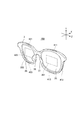
図1及び図2は、本発明を適用した実施形態に係るHMD100の外観構成を示す説明図である。
HMD100は、使用者の頭部に装着された状態で使用者に虚像を視認させる表示装置であり、眼鏡型の形状である。図1は正面側から見た斜視図であり、図2は裏面側から見た斜視図である。なお、図2においては説明の便宜のために右保持部31及び左保持部32の図示を省略する。
[First Embodiment]
1 and 2 are explanatory diagrams showing an external configuration of an HMD 100 according to an embodiment to which the present invention is applied.
The HMD 100 is a display device that allows a user to visually recognize a virtual image while being mounted on the user's head, and has an eyeglass shape. FIG. 1 is a perspective view seen from the front side, and FIG. 2 is a perspective view seen from the back side. In FIG. 2, illustration of the right holding part 31 and the left holding part 32 is omitted for convenience of explanation.

HMD100の本体を構成するフレーム3は、使用者の顔の前に位置して画像を表示する右導光部26及び左導光部28を備え、右導光部26及び左導光部28を保持する眼鏡形状の枠を有する。また、フレーム3は、使用者の側頭部に接する右保持部31及び左保持部32を有する。HMD100は、全体として視力矯正用の眼鏡やサングラス等のフレームと同様の形状を有し、フレーム3は、例えば、眼鏡フレームと相似する形状とすることができる。   The frame 3 constituting the main body of the HMD 100 includes a right light guide unit 26 and a left light guide unit 28 that are positioned in front of the user's face and display an image. A glasses-shaped frame is held. The frame 3 includes a right holding part 31 and a left holding part 32 that are in contact with the user's temporal region. The HMD 100 as a whole has the same shape as a frame such as eyeglasses or sunglasses for correcting vision, and the frame 3 can have a shape similar to, for example, a spectacle frame.

右保持部31及び左保持部32は、眼鏡のテンプル(つる)のようにして、使用者の頭部にフレーム3を保持する。フレーム3には、使用者がHMD100を装着する装着状態において使用者の右眼前に位置し、使用者の右眼に画像を視認させる右導光部26が取り付けられる。また、フレーム3には、HMD100の装着状態において使用者の左眼前に位置し、使用者の左眼に画像を視認させる左導光部28が取り付けられる。右導光部26及び左導光部28は、透光性を有する光学素子(光学部品)であり、眼鏡のレンズと同様に、フレーム3に形成されるリム3a、3bに嵌め込まれて保持される。
また、フレーム3の中央位置には、HMD100の装着状態においてフレーム3を使用者の鼻において指示する鼻当部37、38が設けられる。また、鼻当部37、38が設けられる中央位置は、使用者の眉間の前に位置し、この位置にはカメラ61が設けられる。
The right holding unit 31 and the left holding unit 32 hold the frame 3 on the user's head like a temple of glasses. A right light guide unit 26 is attached to the frame 3 so as to be positioned in front of the user's right eye when the user wears the HMD 100 and to allow the user's right eye to visually recognize an image. In addition, a left light guide unit 28 is attached to the frame 3 so as to be positioned in front of the user's left eye when the HMD 100 is mounted and to allow the user's left eye to visually recognize an image. The right light guide unit 26 and the left light guide unit 28 are optical elements (optical components) having translucency, and are fitted and held in the rims 3a and 3b formed on the frame 3 in the same manner as the lenses of the glasses. The
Further, nose pads 37 and 38 are provided at the center position of the frame 3 to point the frame 3 at the user's nose when the HMD 100 is mounted. The central position where the nose pads 37 and 38 are provided is located in front of the user's eyebrows, and the camera 61 is provided at this position.

フレーム3の左右両端部に位置するフレーム端部35、36は、後述する各種光学系を内蔵する。
カメラ61は、CCDやCMOS等の撮像素子及び撮像レンズ等を備えるデジタルカメラであり、ステレオカメラで構成してもよい。カメラ61は、HMD100の表側方向、換言すれば、HMD100を装着した状態における使用者の視界方向の少なくとも一部の外景(実空間)を撮像する。別の表現では、カメラ61は、使用者の視界と重なる範囲または方向を撮像し、使用者が注視する方向を撮像するということもできる。カメラ61の画角の広さは適宜設定可能であるが、本実施形態では、後述するように、使用者が右導光部26、左導光部28を通して視認する外界を含む。さらに、右導光部26及び左導光部28を通した使用者の視界の全体を撮像できるようにカメラ61の撮像範囲が設定されているとより好ましい。
カメラ61は、制御部140が備える撮像制御部161(図5)の制御に従って撮像を実行し、撮像画像データを撮像制御部161に出力する。
The frame end portions 35 and 36 located at both left and right end portions of the frame 3 incorporate various optical systems described later.
The camera 61 is a digital camera that includes an imaging element such as a CCD or CMOS, an imaging lens, and the like, and may be a stereo camera. The camera 61 images at least a part of the outside scene (real space) in the front side direction of the HMD 100, in other words, the user's viewing direction when the HMD 100 is worn. In another expression, the camera 61 captures a range or direction that overlaps the user's field of view, and captures the direction in which the user gazes. Although the angle of view of the camera 61 can be set as appropriate, in the present embodiment, as will be described later, the camera 61 includes the outside world visually recognized through the right light guide unit 26 and the left light guide unit 28. Furthermore, it is more preferable that the imaging range of the camera 61 is set so that the entire field of view of the user through the right light guide unit 26 and the left light guide unit 28 can be imaged.
The camera 61 performs imaging in accordance with the control of the imaging control unit 161 (FIG. 5) provided in the control unit 140, and outputs captured image data to the imaging control unit 161.

右表示駆動部22、及び、左表示駆動部24は、画像光を形成する。右表示駆動部22が形成する画像光は右導光部26により使用者の右眼に導かれ、左表示駆動部24が形成する画像光は左導光部28により使用者の左眼に導かれる。例えば、図1には、右表示駆動部22がフレーム端部35に収められ、左表示駆動部24がフレーム端部36に収められる構成例を示す。   The right display drive unit 22 and the left display drive unit 24 form image light. The image light formed by the right display drive unit 22 is guided to the right eye of the user by the right light guide unit 26, and the image light formed by the left display drive unit 24 is guided to the user's left eye by the left light guide unit 28. It is burned. For example, FIG. 1 shows a configuration example in which the right display driving unit 22 is housed in the frame end 35 and the left display driving unit 24 is housed in the frame end 36.

図3は、HMD100の構成を示す要部断面図であり、右導光部26とその周囲を支持するフレーム3とを含む位置で、HMD100の縦断面を示す。
右導光部26は、周囲をリム3aに囲まれてフレーム3に指示される。リム3aは溝形状を有し、右導光部26はリム3aに嵌めこまれる。
FIG. 3 is a main part sectional view showing the configuration of the HMD 100, and shows a longitudinal section of the HMD 100 at a position including the right light guide part 26 and the frame 3 supporting the periphery thereof.
The right light guide 26 is instructed to the frame 3 by being surrounded by the rim 3a. The rim 3a has a groove shape, and the right light guide portion 26 is fitted into the rim 3a.

図4は、HMD100の光学系の構成を示す要部平面図である。図4には説明のため使用者の左眼LE及び右眼REを図示する。
表示駆動部22,24は、液晶ディスプレイ241,242(Liquid Crystal Display、以下「LCD241,242」と呼ぶ)、投写光学系251,252等を含む。
FIG. 4 is a main part plan view showing the configuration of the optical system of the HMD 100. FIG. 4 shows the user's left eye LE and right eye RE for explanation.
The display driving units 22 and 24 include liquid crystal displays 241 and 242 (Liquid Crystal Display, hereinafter referred to as “LCDs 241 and 242”), projection optical systems 251 and 252, and the like.

右表示駆動部22は、左表示駆動部24と左右対称に構成される。右表示駆動部22は、LED等の光源と拡散板とを有する右バックライト221、右バックライト221の拡散板から発せられる光の光路上に配置される透過型の右LCD241、及び、右LCD241を透過した画像光Lを導くレンズ群等を備えた右投写光学系251を備える。右LCD241は、複数の画素をマトリクス状に配置した透過型液晶パネルである。   The right display driving unit 22 is configured to be symmetrical with the left display driving unit 24. The right display driving unit 22 includes a right backlight 221 having a light source such as an LED and a diffusion plate, a transmissive right LCD 241 disposed on an optical path of light emitted from the diffusion plate of the right backlight 221, and a right LCD 241. A right projection optical system 251 including a lens group that guides the image light L that has passed through the lens. The right LCD 241 is a transmissive liquid crystal panel in which a plurality of pixels are arranged in a matrix.

左表示駆動部24は、LED等の光源と拡散板とを有する左バックライト222、左バックライト222の拡散板から発せられる光の光路上に配置される透過型の左LCD242、及び、左LCD242を透過した画像光Lを導くレンズ群等を備えた左投写光学系252を備える。左LCD242は、複数の画素をマトリクス状に配置した透過型液晶パネルである。   The left display driving unit 24 includes a left backlight 222 having a light source such as an LED and a diffusion plate, a transmissive left LCD 242 disposed on an optical path of light emitted from the diffusion plate of the left backlight 222, and a left LCD 242. A left projection optical system 252 including a lens group that guides the image light L that has passed through the lens. The left LCD 242 is a transmissive liquid crystal panel in which a plurality of pixels are arranged in a matrix.

右表示駆動部22が発する画像光、及び、左表示駆動部24が発する画像光は、右導光部26及び左導光部28にそれぞれ入射する。
右導光部26及び左導光部28は、光透過性の樹脂等によって形成され、表示駆動部22,24が出力する画像光を、使用者の眼に導く。
Image light emitted from the right display drive unit 22 and image light emitted from the left display drive unit 24 are incident on the right light guide unit 26 and the left light guide unit 28, respectively.
The right light guide unit 26 and the left light guide unit 28 are formed of a light-transmitting resin or the like, and guide the image light output from the display driving units 22 and 24 to the user's eyes.

左投写光学系252は、左LCD242から射出された画像光Lを並行状態の光束にするコリメートレンズを有する。コリメートレンズにより並行状態の光束にされた画像光Lは、左導光部28に入射される。左導光部28は、画像光Lを反射する複数の反射面が形成されたプリズムであり、画像光Lは、左導光部28の内部において複数回の反射を経て左眼LE側に導かれる。左導光部28には、左眼LEの眼前に位置するハーフミラー262A(反射面)が形成される。
ハーフミラー262Aで反射した画像光Lは左眼LEに向けて左導光部28から射出され、この画像光Lが左眼LEの網膜に像を結び、使用者に画像を視認させる。
The left projection optical system 252 includes a collimator lens that converts the image light L emitted from the left LCD 242 into a light beam in a parallel state. The image light L converted into a parallel light beam by the collimator lens is incident on the left light guide unit 28. The left light guide unit 28 is a prism formed with a plurality of reflecting surfaces that reflect the image light L, and the image light L is guided to the left eye LE side through a plurality of reflections inside the left light guide unit 28. It is burned. The left light guide 28 is formed with a half mirror 262A (reflection surface) located in front of the left eye LE.
The image light L reflected by the half mirror 262A is emitted from the left light guide unit 28 toward the left eye LE, and this image light L forms an image on the retina of the left eye LE to allow the user to visually recognize the image.

右投写光学系251は、右LCD241から射出された画像光Lを並行状態の光束にするコリメートレンズを有する。コリメートレンズにより並行状態の光束にされた画像光Lは、右導光部26に入射される。右導光部26は、画像光Lを反射する複数の反射面が形成されたプリズムであり、画像光Lは、右導光部26の内部において複数回の反射を経て右眼RE側に導かれる。右導光部26には、右眼REの眼前に位置するハーフミラー261A(反射面)が形成される。
ハーフミラー261Aで反射した画像光Lは右眼REに向けて右導光部26から射出され、この画像光Lが右眼REの網膜に像を結び、使用者に画像を視認させる。
The right projection optical system 251 includes a collimator lens that converts the image light L emitted from the right LCD 241 into a light beam in a parallel state. The image light L converted into a parallel light beam by the collimator lens is incident on the right light guide unit 26. The right light guide unit 26 is a prism formed with a plurality of reflecting surfaces that reflect the image light L, and the image light L is guided to the right eye RE side through a plurality of reflections inside the right light guide unit 26. It is burned. A half mirror 261A (reflection surface) located in front of the right eye RE is formed in the right light guide unit 26.
The image light L reflected by the half mirror 261A is emitted from the right light guide unit 26 toward the right eye RE, and this image light L forms an image on the retina of the right eye RE to make the user visually recognize the image.

使用者の右眼REには、ハーフミラー261Aで反射した画像光Lと、右導光部26を透過した外光OLとが入射する。左眼LEには、ハーフミラー262Aで反射した画像光Lと、左導光部28を透過した外光OLとが入射する。このように、HMD100は、内部で処理した画像の画像光Lと外光OLとを重ねて使用者の眼に入射させ、使用者にとっては、右導光部26及び左導光部28を透かして外景が見え、この外景に重ねて、画像光Lによる画像が視認される。このように、HMD100は、シースルー型の表示装置として機能する。
本実施形態において、右導光部26及び左導光部28は実像を結像させる構成ではなく、虚像を形成して、使用者に画像を視認させるものであるが、結果として使用者に画像を認識させる意味で、本実施形態では「画像を表示する」と表現する。言い換えれば、HMD100は、実像であるか虚像であるかを問わず画像を構成する画像光Lを使用者に向けて出射し、使用者に画像を認識させるものであればよい。
The image light L reflected by the half mirror 261A and the external light OL transmitted through the right light guide 26 are incident on the user's right eye RE. The image light L reflected by the half mirror 262A and the external light OL transmitted through the left light guide 28 are incident on the left eye LE. In this way, the HMD 100 superimposes the image light L of the internally processed image and the external light OL on the eyes of the user, and for the user, the right light guide unit 26 and the left light guide unit 28 are watermarked. The outside scene can be seen, and the image by the image light L is visually recognized over the outside scene. As described above, the HMD 100 functions as a see-through display device.
In the present embodiment, the right light guide unit 26 and the left light guide unit 28 are not configured to form a real image, but form a virtual image so that the user can visually recognize the image. In this embodiment, it is expressed as “display an image”. In other words, the HMD 100 only needs to emit image light L constituting an image toward the user regardless of whether it is a real image or a virtual image, and cause the user to recognize the image.

なお、左投写光学系252と左導光部28とを総称して「左表示部」と呼び、右投写光学系251と右導光部26とを総称して「右表示部」と呼ぶこともできる。右表示部及び左表示部の構成は上記の例に限定されず、画像光を用いて使用者の眼前に虚像を形成する限りにおいて任意の方式を用いることができ、例えば、回折格子を用いても良いし、半透過反射膜を用いても良い。   The left projection optical system 252 and the left light guide unit 28 are collectively referred to as “left display unit”, and the right projection optical system 251 and the right light guide unit 26 are collectively referred to as “right display unit”. You can also. The configuration of the right display unit and the left display unit is not limited to the above example, and any method can be used as long as a virtual image is formed in front of the user's eyes using image light. For example, using a diffraction grating Alternatively, a transflective film may be used.

図2に示すように、右導光部26及び左導光部28は、使用者の右眼及び左眼のそれぞれに、矩形の画像を視認させる。右眼に対応する矩形の右表示部301は、ハーフミラー261Aにより形成される矩形の画像表示領域であり、右投写光学系251が形成する画像光である。左表示部302は、ハーフミラー262Aにより形成される矩形の画像表示領域であり、右投写光学系251が形成する画像光である。   As shown in FIG. 2, the right light guide unit 26 and the left light guide unit 28 cause each of the user's right eye and left eye to visually recognize a rectangular image. A rectangular right display unit 301 corresponding to the right eye is a rectangular image display region formed by the half mirror 261A, and is image light formed by the right projection optical system 251. The left display unit 302 is a rectangular image display area formed by the half mirror 262A, and is image light formed by the right projection optical system 251.

このように、HMD100が画像を表示する間、使用者には、ハーフミラー261Aが右表示部301の内部に位置する四角形の領域として見え、ハーフミラー262Aが、左表示部302の内部に位置する略四角形の領域として見える。ハーフミラー261A、262Aの全体が、上述したように外光を透過するので、使用者には、右表示部301及び左表示部302の全体が、外景に重なって視認される。   In this way, while the HMD 100 displays an image, the user sees the half mirror 261A as a quadrangular region located inside the right display unit 301, and the half mirror 262A is located inside the left display unit 302. It appears as a roughly rectangular area. Since the entire half mirrors 261A and 262A transmit the external light as described above, the entire right display unit 301 and the left display unit 302 are visually recognized by the user while overlapping the outside scene.

カメラ61は、図1に示したようにフレーム3の前面の中央位置に配置され、使用者の両眼が向く方向、すなわち使用者にとって前方を撮像する。言い換えれば、カメラ61の撮像方向すなわち画角は、使用者の前方を向き、使用者が実空間(外景)を見る場合の視線方向を向く。カメラ61は、撮像レンズとして、いわゆる広角レンズを備え、広い画角を撮像できる構成としてもよい。広角レンズには、超広角レンズ、準広角レンズと呼ばれるレンズを含んでもよいし、単焦点レンズであってもズームレンズであってもよく、複数のレンズからなるレンズ群をカメラ61が備える構成であってもよい。   As shown in FIG. 1, the camera 61 is arranged at the center position on the front surface of the frame 3, and images the direction in which both eyes of the user face, that is, the front for the user. In other words, the imaging direction of the camera 61, that is, the angle of view, faces the front of the user and faces the line of sight when the user looks at the real space (outside scene). The camera 61 may include a so-called wide-angle lens as an imaging lens, and may be configured to capture a wide angle of view. The wide-angle lens may include a lens called a super-wide-angle lens or a quasi-wide-angle lens, may be a single focus lens or a zoom lens, and the camera 61 includes a lens group including a plurality of lenses. There may be.

以下の説明では、図1に示すように、フレーム3を基準とした方向をX、Y、Zの直交座標により説明する。X方向は、右導光部26及び左導光部28を含むフレーム3の前面に対し接近及び離隔する方向であり、右保持部31及び左保持部32の延長方向に相当する。X方向は、使用者の視界に対する奥行き方向とも言える。また、Y方向は、HMD100の高さ方向、より具体的には、フレーム3の高さ方向であり、HMD100の装着状態において使用者の視界の鉛直方向である。Z方向は、フレーム3の幅方向、より具体的には、右導光部26と左導光部28とが並ぶ方向に対応し、HMD100の装着状態において使用者の右眼と左眼とを結ぶ、略水平な線に沿う方向である。   In the following description, as shown in FIG. 1, the direction with reference to the frame 3 will be described using X, Y, and Z orthogonal coordinates. The X direction is a direction approaching and separating from the front surface of the frame 3 including the right light guide unit 26 and the left light guide unit 28, and corresponds to the extending direction of the right holding unit 31 and the left holding unit 32. The X direction can also be said to be a depth direction with respect to the user's field of view. The Y direction is the height direction of the HMD 100, more specifically, the height direction of the frame 3, and is the vertical direction of the user's field of view when the HMD 100 is mounted. The Z direction corresponds to the width direction of the frame 3, more specifically, the direction in which the right light guide unit 26 and the left light guide unit 28 are arranged, and the right and left eyes of the user when the HMD 100 is worn. It is a direction along a substantially horizontal line to be connected.

HMD100は、外部からの入力操作を検出する外部センサー400、及び、タッチパッド401、402を備える。
外部センサー400は、右センサー部410、及び、左センサー部420を含んで構成される。
タッチパッド401、402は、HMD100の装着状態においてHMD100の側方に面して配置される。より詳細には、タッチパッド401は、右保持部31においてフレーム3の外側の面に配置され、タッチパッド402は、左保持部32においてフレーム3の外側の面に配置される。タッチパッド401、402は、それぞれ、右保持部31と左保持部32の形状に合わせて、長手形状であってもよいし、矩形であってもよい。HMD100の装着状態で、使用者は、例えば右手でタッチパッド401を操作し、左手でタッチパッド402を操作できる。
タッチパッド401、402は、接触操作を検出して操作位置を特定する操作部(操作受付部)であり、例えば静電容量式あるいは感圧式のタッチパッドである。
The HMD 100 includes an external sensor 400 that detects an input operation from the outside, and touch pads 401 and 402.
The external sensor 400 includes a right sensor unit 410 and a left sensor unit 420.
The touch pads 401 and 402 are arranged facing the side of the HMD 100 when the HMD 100 is attached. More specifically, the touch pad 401 is disposed on the outer surface of the frame 3 in the right holding unit 31, and the touch pad 402 is disposed on the outer surface of the frame 3 in the left holding unit 32. The touch pads 401 and 402 may have a long shape or a rectangular shape in accordance with the shapes of the right holding unit 31 and the left holding unit 32, respectively. With the HMD 100 mounted, the user can operate the touch pad 401 with the right hand and the touch pad 402 with the left hand, for example.
The touch pads 401 and 402 are operation units (operation reception units) that detect a contact operation and specify an operation position, and are, for example, capacitive or pressure-sensitive touch pads.

フレーム3の前面側には、右センサー部410、及び、左センサー部420が配置される。
右センサー部410は、センサー411、412、413で構成される。センサー411、412、413は、右導光部26の周囲に配置される。詳細には、センサー411は右導光部26の上方に位置し、Z方向に延びるように配置され、横長の検出領域を有する。また、センサー412は右導光部26の側方に、Y方向に延びるように配置され、縦長の検出領域を有する。また、センサー413は、右導光部26の下方において、Z方向に延びるように配置され、横長の検出領域を有する。
右センサー部410の各センサーは、右導光部26を透過する外光OLを遮らないように、右導光部26に重ならないように配置されることが好ましい。なお、センサー411、412、413が外光OLを透過可能である場合、センサー411、412、413が右導光部26に重なってもよい。
A right sensor unit 410 and a left sensor unit 420 are arranged on the front side of the frame 3.
The right sensor unit 410 includes sensors 411, 412, and 413. The sensors 411, 412, and 413 are arranged around the right light guide unit 26. Specifically, the sensor 411 is located above the right light guide unit 26 and is disposed so as to extend in the Z direction, and has a horizontally long detection region. The sensor 412 is disposed on the side of the right light guide unit 26 so as to extend in the Y direction, and has a vertically long detection region. The sensor 413 is disposed below the right light guide portion 26 so as to extend in the Z direction, and has a horizontally long detection region.
Each sensor of the right sensor unit 410 is preferably disposed so as not to overlap the right light guide unit 26 so as not to block the external light OL transmitted through the right light guide unit 26. When the sensors 411, 412, and 413 can transmit the external light OL, the sensors 411, 412, and 413 may overlap the right light guide unit 26.

左センサー部420は、センサー421、422、423で構成される。センサー421、422、423は、左導光部28の周囲に配置される。詳細には、センサー421は左導光部28の上方に位置し、Z方向に延びるように配置され、横長の検出領域を有する。また、センサー422は左導光部28の側方に、Y方向に延びるように配置され、縦長の検出領域を有する。また、センサー423は、左導光部28の下方において、Z方向に延びるように配置され、横長の検出領域を有する。左センサー部420を構成する各センサーは、左導光部28を透過する外光OLを遮らないように、左導光部28に重ならないように配置されることが好ましい。なお、センサー421、422、423が外光OLを透過可能である場合、センサー421、422、423が左導光部28に重なってもよい。
右センサー部410は、右導光部26の周辺に対応する検出部を構成し、左センサー部420は、左導光部28の周辺に対応する検出部を構成する。
The left sensor unit 420 includes sensors 421, 422, and 423. The sensors 421, 422, and 423 are disposed around the left light guide unit 28. Specifically, the sensor 421 is located above the left light guide 28 and is disposed so as to extend in the Z direction, and has a horizontally long detection region. The sensor 422 is disposed on the side of the left light guide 28 so as to extend in the Y direction, and has a vertically long detection region. The sensor 423 is disposed below the left light guide 28 so as to extend in the Z direction, and has a horizontally long detection region. Each sensor constituting the left sensor unit 420 is preferably arranged so as not to overlap the left light guide unit 28 so as not to block the external light OL transmitted through the left light guide unit 28. When the sensors 421, 422, and 423 can transmit the external light OL, the sensors 421, 422, and 423 may overlap the left light guide unit 28.
The right sensor unit 410 configures a detection unit corresponding to the periphery of the right light guide unit 26, and the left sensor unit 420 configures a detection unit corresponding to the periphery of the left light guide unit 28.

センサー411、412、413、421、422、423は、物体の接近を検出する近接センサーであり、例えば静電容量式のセンサーで構成される。センサー411、412、413、421、422、423のそれぞれの検出範囲はHMD100の前方に広がる。つまり、右センサー部410及び左センサー部420は、HMD100の前方から接近する物体が、検出範囲の外側から検出範囲内に接近した場合に、この物体を検出する。ここで、右センサー部410及び左センサー部420が検出する実空間の物体を、操作体(指示体)とする。   The sensors 411, 412, 413, 421, 422, and 423 are proximity sensors that detect the approach of an object, and are configured by, for example, capacitive sensors. The detection ranges of the sensors 411, 412, 413, 421, 422, and 423 extend in front of the HMD 100. That is, the right sensor unit 410 and the left sensor unit 420 detect this object when an object approaching from the front of the HMD 100 approaches the detection range from the outside of the detection range. Here, an object in real space detected by the right sensor unit 410 and the left sensor unit 420 is an operation body (indicator).

近接センサーは、例えば、近接センサーに接触しない操作体であって、近接センサーから1cm以内に存在する操作体を検出できることが好ましい。近接センサーに接触する操作体を検出してもよい。また、HMD100を装着した状態における誤検知を防止または抑制できることが好ましく、例えば、HMD100の装着状態における誤検知抑制機能として、感度調整、感度のカスタマイズ等を実行できる構成としてもよい。また、HMD100の装着状態において右導光部26、左導光部28と使用者の顔との間における操作体の接近を検出しない、検出方向に指向性が設定された近接センサーを利用してもよい。   It is preferable that the proximity sensor is, for example, an operating body that does not contact the proximity sensor and can detect an operating body existing within 1 cm from the proximity sensor. An operating body that contacts the proximity sensor may be detected. In addition, it is preferable that erroneous detection in a state where the HMD 100 is worn can be prevented or suppressed. For example, as a false detection suppression function in a state where the HMD 100 is worn, sensitivity adjustment, sensitivity customization, or the like may be performed. In addition, when the HMD 100 is mounted, a proximity sensor that does not detect the approach of the operating body between the right light guide unit 26, the left light guide unit 28, and the user's face and has directivity set in the detection direction is used. Also good.

図3に示すように、右導光部26の上方に位置するセンサー411は、矢印A11で示すようにフレーム3の前方から接近する操作体を検出できる。また、矢印A13で示すようにフレーム3の後方から接近する操作体を検出可能な構成としてもよい。また、矢印A12で示すように上方から接近する操作体を検出できる。つまり、センサー411は、X方向、及びY方向に接近する物体(操作体)を検出可能である。センサー421も同様である。
また、右導光部26の下方に位置するセンサー413は、矢印A31で示すようにフレーム3の前方から接近する操作体を検出できる。また、矢印A33で示すようにフレーム3の後方から接近する操作体を検出可能な構成としてもよい。また、矢印A32で示すように下方から接近する操作体を検出できる。つまり、センサー413は、X方向、及びY方向に接近する物体を検出可能である。センサー423も同様である。
As shown in FIG. 3, the sensor 411 positioned above the right light guide 26 can detect an operating body approaching from the front of the frame 3 as indicated by an arrow A <b> 11. Moreover, it is good also as a structure which can detect the operating body approaching from the back of the flame | frame 3 as shown by arrow A13. Further, an operating body approaching from above can be detected as indicated by an arrow A12. That is, the sensor 411 can detect an object (operation body) approaching in the X direction and the Y direction. The same applies to the sensor 421.
In addition, the sensor 413 located below the right light guide unit 26 can detect an operating body approaching from the front of the frame 3 as indicated by an arrow A31. Moreover, it is good also as a structure which can detect the operation body approaching from the back of the flame | frame 3 as shown by arrow A33. In addition, as shown by an arrow A32, an operating body approaching from below can be detected. That is, the sensor 413 can detect an object approaching in the X direction and the Y direction. The same applies to the sensor 423.

また、センサー412、422は、X方向、及び、Z方向に接近する物体を検出可能である。また、センサー412、422のそれぞれは、センサー412、422の検出可能範囲において操作体がX方向あるいはY方向に移動した場合、この移動を検出する。   Further, the sensors 412 and 422 can detect an object approaching in the X direction and the Z direction. Each of the sensors 412 and 422 detects this movement when the operating body moves in the X direction or the Y direction within the detectable range of the sensors 412 and 422.

また、センサー411、421のそれぞれは、センサー411の検出可能範囲において操作体がX方向あるいはZ方向に移動した場合、この移動を検出する。また、センサー413、423のそれぞれは、センサー413、423の検出可能範囲において操作体がX方向あるいはZ方向に移動した場合、この移動を検出する。   Each of the sensors 411 and 421 detects this movement when the operating body moves in the X direction or the Z direction within the detectable range of the sensor 411. Each of the sensors 413 and 423 detects this movement when the operating body moves in the X direction or the Z direction within the detectable range of the sensors 413 and 423.

HMD100は、右センサー部410の各センサーの検出値、及び、左センサー部420の各センサーの検出値に基づき、物体の接近を検出可能である。また、各センサーの検出値を解析することにより、検出範囲内に位置する物体の移動を検出できる。   The HMD 100 can detect the approach of an object based on the detection value of each sensor of the right sensor unit 410 and the detection value of each sensor of the left sensor unit 420. Further, by analyzing the detection value of each sensor, it is possible to detect the movement of an object located within the detection range.

図5は、HMD100を構成する各部の機能ブロック図である。
HMD100は、大別して、処理部10及び画像表示部20を備える。
画像表示部20は、右表示駆動部22及び左表示駆動部24を含み、右導光部26及び左導光部28に対して画像光を供給する。画像表示部20は、フレーム3に配置される構成部を含み、具体的には、カメラ61、9軸センサー66、外部センサー400、タッチパッド401、402を含む。例えば、図1には、右表示駆動部22がフレーム端部35に収められ、左表示駆動部24がフレーム端部36に収められる構成例を示す。画像表示部20を構成する他の部位は、フレーム3のフレーム端部35、36、或いは、フレーム3の前面を含む部分に配置してもよい。
FIG. 5 is a functional block diagram of each part constituting the HMD 100.
The HMD 100 roughly includes a processing unit 10 and an image display unit 20.
The image display unit 20 includes a right display drive unit 22 and a left display drive unit 24, and supplies image light to the right light guide unit 26 and the left light guide unit 28. The image display unit 20 includes components disposed on the frame 3, and specifically includes a camera 61, a nine-axis sensor 66, an external sensor 400, and touch pads 401 and 402. For example, FIG. 1 shows a configuration example in which the right display driving unit 22 is housed in the frame end 35 and the left display driving unit 24 is housed in the frame end 36. Other parts constituting the image display unit 20 may be arranged on the frame end portions 35 and 36 of the frame 3 or a portion including the front surface of the frame 3.

画像表示部20が備える右表示駆動部22、左表示駆動部24、カメラ61、9軸センサー66、外部センサー400、及びタッチパッド401、402の各部は、インターフェイス25に接続される。   The right display drive unit 22, the left display drive unit 24, the camera 61, the 9-axis sensor 66, the external sensor 400, and the touch pads 401 and 402 included in the image display unit 20 are connected to the interface 25.

インターフェイス25は、処理部10が有する制御部140に接続される。制御部140は、後述するように、画像処理部160、撮像制御部161、入力検出部162、入力解析部163、処理実行部164、通信制御部170、及び表示制御部190として機能する。インターフェイス25は、制御部140の各部と、処理部10の各部とを相互に接続し、各種データ及び信号を送受信させる。
例えば、インターフェイス25は、表示制御部190が出力する制御信号を、右表示駆動部22及び左表示駆動部24に出力する。また、インターフェイス25は、表示制御部190から送信される制御信号を、対応する右バックライト制御部201又は左バックライト制御部202に出力する。
また、インターフェイス25は、カメラ61、9軸センサー66、外部センサー400、及びタッチパッド401、402のそれぞれを、制御部140に接続する。
The interface 25 is connected to the control unit 140 included in the processing unit 10. As will be described later, the control unit 140 functions as an image processing unit 160, an imaging control unit 161, an input detection unit 162, an input analysis unit 163, a processing execution unit 164, a communication control unit 170, and a display control unit 190. The interface 25 connects each unit of the control unit 140 and each unit of the processing unit 10 to transmit / receive various data and signals.
For example, the interface 25 outputs a control signal output from the display control unit 190 to the right display drive unit 22 and the left display drive unit 24. Further, the interface 25 outputs a control signal transmitted from the display control unit 190 to the corresponding right backlight control unit 201 or left backlight control unit 202.
The interface 25 connects the camera 61, the 9-axis sensor 66, the external sensor 400, and the touch pads 401 and 402 to the control unit 140.

右表示駆動部22は、上述した右バックライト221、右LCD241、及び右投写光学系251を備える。また、右表示駆動部22は、右バックライト(BL)221を制御する右バックライト(BL)制御部201、及び、右LCD241を駆動する右LCD制御部211を備える。
右バックライト制御部201は、表示制御部190が送信する制御信号に従って、右バックライト221を駆動する。右LCD制御部211は、画像処理部160が送信する信号及び表示制御部190が送信する信号に基づいて、右LCD241を駆動する。
The right display drive unit 22 includes the right backlight 221, the right LCD 241, and the right projection optical system 251 described above. The right display drive unit 22 includes a right backlight (BL) control unit 201 that controls the right backlight (BL) 221 and a right LCD control unit 211 that drives the right LCD 241.
The right backlight control unit 201 drives the right backlight 221 in accordance with a control signal transmitted from the display control unit 190. The right LCD control unit 211 drives the right LCD 241 based on the signal transmitted from the image processing unit 160 and the signal transmitted from the display control unit 190.

左表示駆動部24は、右表示駆動部22と同様の構成を有する。左表示駆動部24は、上述した左バックライト222、左LCD242、及び左投写光学系252を備える。また、左表示駆動部24は、左バックライト222を駆動する左バックライト制御部202、及び、左LCD242を駆動する左LCD制御部212を備える。   The left display drive unit 24 has the same configuration as the right display drive unit 22. The left display driving unit 24 includes the left backlight 222, the left LCD 242 and the left projection optical system 252 described above. The left display drive unit 24 includes a left backlight control unit 202 that drives the left backlight 222 and a left LCD control unit 212 that drives the left LCD 242.

左バックライト制御部202は、表示制御部190が送信する制御信号に従って、左バックライト222を駆動する。左LCD制御部212は、画像処理部160が送信する信号及び表示制御部190が送信する信号に基づいて、左LCD242を駆動する。
なお、右バックライト制御部201と、右LCD制御部211と、右バックライト221と、右LCD241とを総称して、右の「画像光生成部」とも呼ぶ。同様に、左バックライト制御部202と、左LCD制御部212と、左バックライト222と、左LCD242とを総称して、左の「画像光生成部」とも呼ぶ。
The left backlight control unit 202 drives the left backlight 222 according to the control signal transmitted from the display control unit 190. The left LCD control unit 212 drives the left LCD 242 based on the signal transmitted from the image processing unit 160 and the signal transmitted from the display control unit 190.
The right backlight control unit 201, the right LCD control unit 211, the right backlight 221 and the right LCD 241 are collectively referred to as a right “image light generation unit”. Similarly, the left backlight control unit 202, the left LCD control unit 212, the left backlight 222, and the left LCD 242 are collectively referred to as a left “image light generation unit”.

カメラ61は、撮像制御部161から入力される制御データに従って撮像を実行し、撮像画像データを、インターフェイス25を介して撮像制御部161に出力する。   The camera 61 executes imaging according to control data input from the imaging control unit 161, and outputs captured image data to the imaging control unit 161 via the interface 25.

9軸センサー66は、加速度(3軸)、角速度(3軸)、地磁気(3軸)を検出するモーションセンサー(慣性センサー)である。9軸センサー66は、複数のセンサーを統合したセンサーユニットであってもよい。9軸センサー66は、インターフェイス25を介して制御部140に接続され、制御部140の制御に従って、所定の周期(サンプリング周波数)で検出を実行し、検出値を制御部140に出力する。制御部140は、HMD100が使用者の頭部に装着された状態で、9軸センサー66の検出値に基づいて使用者の頭部の動きを検出できる。   The nine-axis sensor 66 is a motion sensor (inertial sensor) that detects acceleration (three axes), angular velocity (three axes), and geomagnetism (three axes). The 9-axis sensor 66 may be a sensor unit in which a plurality of sensors are integrated. The 9-axis sensor 66 is connected to the control unit 140 via the interface 25, performs detection at a predetermined cycle (sampling frequency) under the control of the control unit 140, and outputs the detection value to the control unit 140. The control unit 140 can detect the movement of the user's head based on the detection value of the 9-axis sensor 66 in a state where the HMD 100 is mounted on the user's head.

図5に示す外部センサー400は、右センサー部410及び左センサー部420を含み、右センサー部410と左センサー部420のそれぞれがインターフェイス25に接続されてもよい。例えば、右センサー部410のセンサー411、412、413がユニット化されてインターフェイス25に接続されてもよい。また、左センサー部420のセンサー421、422、423が、ユニット化されてインターフェイス25に接続されてもよい。或いは、センサー411、412、413、421、422、423のそれぞれが、インターフェイス25に接続されてもよい。
外部センサー400は、入力検出部162の制御に従って、所定の周期(サンプリング周波数)で検出を実行し、検出値を入力検出部162に出力する。
The external sensor 400 illustrated in FIG. 5 includes a right sensor unit 410 and a left sensor unit 420, and each of the right sensor unit 410 and the left sensor unit 420 may be connected to the interface 25. For example, the sensors 411, 412, and 413 of the right sensor unit 410 may be unitized and connected to the interface 25. Further, the sensors 421, 422, and 423 of the left sensor unit 420 may be unitized and connected to the interface 25. Alternatively, each of the sensors 411, 412, 413, 421, 422, and 423 may be connected to the interface 25.
The external sensor 400 performs detection at a predetermined cycle (sampling frequency) according to the control of the input detection unit 162, and outputs the detection value to the input detection unit 162.

タッチパッド401、402は、それぞれ、インターフェイス25に接続される。タッチパッド401、402は、入力検出部162の制御に従って、所定の周期(サンプリング周波数)で検出を実行し、検出値を入力検出部162に出力する。
ここで、タッチパッド401、402が、検出値を解析する検出回路(図示略)を備え、この検出回路がインターフェイス25に接続される構成としてもよい。この場合、タッチパッド401、402は検出回路の制御により検出を実行し、検出回路は、タッチパッド401、402で接触操作を検出し、操作位置を特定し、操作位置を示すデータを入力検出部162に出力する。また、入力検出部162が、タッチパッド401、402から入力される検出値に基づき、接触操作を検出し、操作位置を特定してもよい。
The touch pads 401 and 402 are connected to the interface 25, respectively. The touch pads 401 and 402 execute detection at a predetermined cycle (sampling frequency) according to the control of the input detection unit 162, and output the detection value to the input detection unit 162.
Here, the touch pads 401 and 402 may include a detection circuit (not shown) for analyzing the detection value, and the detection circuit may be connected to the interface 25. In this case, the touch pads 401 and 402 execute detection by control of the detection circuit, and the detection circuit detects a touch operation with the touch pads 401 and 402, specifies the operation position, and inputs data indicating the operation position to the input detection unit. It outputs to 162. Further, the input detection unit 162 may detect a contact operation based on detection values input from the touch pads 401 and 402 and specify the operation position.

処理部10は、HMD100を制御する。処理部10は、使用者の操作を受け付ける操作部111を備える。操作部111は、例えば、HMD100の電源のオン/オフの指示を行う電源スイッチ(図示略)、及び、その他の各種スイッチを備える。
処理部10を構成する各部は、例えば、フレーム3のフレーム端部35、36に収容される。また、処理部10の全部または一部を、右保持部31や左保持部32に収容してもよいし、フレーム3とは別体として構成される筐体に納めてもよい。この場合、当該筐体とフレーム3の内部の画像表示部20とを、ケーブルで有線接続してもよいし、無線通信により接続してもよい。
The processing unit 10 controls the HMD 100. The processing unit 10 includes an operation unit 111 that receives a user's operation. The operation unit 111 includes, for example, a power switch (not shown) for instructing the power on / off of the HMD 100 and other various switches.
Each part which comprises the process part 10 is accommodated in the frame edge parts 35 and 36 of the flame | frame 3, for example. Further, all or a part of the processing unit 10 may be accommodated in the right holding unit 31 and the left holding unit 32, or may be housed in a housing configured separately from the frame 3. In this case, the casing and the image display unit 20 inside the frame 3 may be connected by cable or by wireless communication.

処理部10は、制御部140、入力情報取得部110、及び、記憶部120を有する。
入力情報取得部110は、操作部111に接続される。入力情報取得部110は、操作部111から入力される信号に基づき、使用者の操作を受け付ける。入力情報取得部110は、操作部111における操作内容を示すデータを制御部140に出力する。
The processing unit 10 includes a control unit 140, an input information acquisition unit 110, and a storage unit 120.
The input information acquisition unit 110 is connected to the operation unit 111. The input information acquisition unit 110 receives a user operation based on a signal input from the operation unit 111. The input information acquisition unit 110 outputs data indicating the operation content in the operation unit 111 to the control unit 140.

処理部10は、電源部113を備える。電源部113は、例えば一次電池、二次電池、或いはキャパシターを有し、処理部10及び画像表示部20の各部に電源部113から電源が供給される。電源部113からの電源供給状態は、電源スイッチ(図示略)の操作、及び、制御部140が実行するプログラムの実行状況に応じて、制御部140が制御する。   The processing unit 10 includes a power supply unit 113. The power supply unit 113 includes, for example, a primary battery, a secondary battery, or a capacitor, and power is supplied from the power supply unit 113 to each unit of the processing unit 10 and the image display unit 20. The power supply state from the power supply unit 113 is controlled by the control unit 140 according to the operation of a power switch (not shown) and the execution status of the program executed by the control unit 140.

記憶部120は、不揮発性の記憶装置であって、種々のコンピュータープログラム、及び、これらのプログラムに係るデータを記憶する。また、記憶部120は、右表示駆動部22及び左表示駆動部24により表示する静止画像や動画像のデータを記憶しても良い。
記憶部120は、設定データ121を記憶する。設定データ121は、制御部140が使用する各種の設定値を含む。設定データ121が含む設定値は、予め操作部111の操作で入力された値であってもよいし、通信部117を介して外部の機器(図示略)または他の装置(図示略)から設定値を受信して記憶してもよい。
また、記憶部120は、入力解析データ122、及び、画像データ123を記憶する。
The storage unit 120 is a nonvolatile storage device, and stores various computer programs and data related to these programs. The storage unit 120 may store still image data and moving image data displayed by the right display drive unit 22 and the left display drive unit 24.
The storage unit 120 stores setting data 121. The setting data 121 includes various setting values used by the control unit 140. The setting value included in the setting data 121 may be a value input in advance by operating the operation unit 111, or set from an external device (not shown) or another device (not shown) via the communication unit 117. The value may be received and stored.
In addition, the storage unit 120 stores input analysis data 122 and image data 123.

制御部140は、プログラムを実行するCPU(図示略)、CPUが実行するプログラムやデータを一時的に格納するRAM(図示略)、及び、CPUが実行する基本制御プログラムやデータを不揮発的に記憶するROM(図示略)を備える。制御部140は、記憶部120が記憶するコンピュータープログラムを読み出して実行し、オペレーティングシステム(OS)150、画像処理部160、撮像制御部161、入力検出部162、入力解析部163、処理実行部164、通信制御部170、及び、表示制御部190として機能する。   The control unit 140 stores a CPU (not shown) for executing a program, a RAM (not shown) for temporarily storing a program and data executed by the CPU, and a basic control program and data executed by the CPU in a nonvolatile manner. ROM (not shown). The control unit 140 reads out and executes the computer program stored in the storage unit 120, and executes an operating system (OS) 150, an image processing unit 160, an imaging control unit 161, an input detection unit 162, an input analysis unit 163, and a process execution unit 164. , Function as a communication control unit 170 and a display control unit 190.

撮像制御部161は、カメラ61を制御して撮像を実行させ、撮像画像データを生成し、記憶部120に一時的に記憶する。また、カメラ61が撮像画像データを生成する回路を含むカメラユニットとして構成される場合、撮像制御部161は撮像画像データをカメラ61から取得して、記憶部120に一時的に記憶する。   The imaging control unit 161 controls the camera 61 to execute imaging, generates captured image data, and temporarily stores the captured image data in the storage unit 120. When the camera 61 is configured as a camera unit including a circuit that generates captured image data, the imaging control unit 161 acquires captured image data from the camera 61 and temporarily stores the captured image data in the storage unit 120.

画像処理部160は、右表示駆動部22及び左表示駆動部24により表示させる画像データに基づいて、画像表示用の信号を生成し、右表示駆動部22及び左表示駆動部24に送信する。画像処理部160が生成する信号は、垂直同期信号、水平同期信号、クロック信号、アナログ画像信号等であってもよい。
また、画像処理部160は、必要に応じて、画像データの解像度を右表示駆動部22及び左表示駆動部24に適した解像度に変換する解像度変換処理を行ってもよい。また、画像処理部160は、画像データの輝度や彩度を調整する画像調整処理、3D画像データから2D画像データを作成し、或いは2D画像データから3D画像データを生成する2D/3D変換処理等を実行してもよい。画像処理部160は、これらの画像処理を実行した場合、処理後の画像データに基づき画像を表示するための信号を生成して送信する。
The image processing unit 160 generates an image display signal based on the image data displayed by the right display driving unit 22 and the left display driving unit 24 and transmits the signal to the right display driving unit 22 and the left display driving unit 24. The signal generated by the image processing unit 160 may be a vertical synchronization signal, a horizontal synchronization signal, a clock signal, an analog image signal, or the like.
Further, the image processing unit 160 may perform resolution conversion processing for converting the resolution of the image data to a resolution suitable for the right display driving unit 22 and the left display driving unit 24 as necessary. The image processing unit 160 also performs image adjustment processing for adjusting the brightness and saturation of image data, 2D image data is created from 3D image data, or 2D / 3D conversion processing is performed to generate 3D image data from 2D image data. May be executed. When these image processes are executed, the image processing unit 160 generates and transmits a signal for displaying an image based on the processed image data.

表示制御部190は、右表示駆動部22及び左表示駆動部24を制御する制御信号を生成し、この制御信号により、右表示駆動部22及び左表示駆動部24のそれぞれによる画像光の生成及び射出を制御する。具体的には、右LCD制御部211による右LCD241の駆動ON/OFF、右バックライト制御部201による右バックライト221の駆動ON/OFFを制御する。また、表示制御部190は、左LCD制御部212による左LCD242の駆動ON/OFF、左バックライト制御部202による左バックライト222の駆動ON/OFFを制御する。   The display control unit 190 generates a control signal for controlling the right display drive unit 22 and the left display drive unit 24, and generates and generates image light by each of the right display drive unit 22 and the left display drive unit 24 based on the control signal. Control injection. Specifically, the right LCD 241 is controlled to be turned on / off by the right LCD control unit 211, and the right backlight 221 is turned on / off by the right backlight control unit 201. Further, the display control unit 190 controls the driving of the left LCD 242 by the left LCD control unit 212 and the driving of the left backlight 222 by the left backlight control unit 202.

制御部140は、記憶部120が記憶するコンテンツのデータ(図示略)に基づく画像や、HMD100の設定を行うメニュー画面の画像等を表示する。記憶部120が記憶するコンテンツのデータは、テキストデータ、静止画像データ、動画像データ、及び音声データ等を含むことができる。また、制御部140は、カメラ61で撮像する撮像画像、または、撮像画像から生成する表示用の画像を、画像表示部20により表示してもよい。   The control unit 140 displays an image based on content data (not shown) stored in the storage unit 120, a menu screen image for setting the HMD 100, and the like. The content data stored in the storage unit 120 may include text data, still image data, moving image data, audio data, and the like. Further, the control unit 140 may cause the image display unit 20 to display a captured image captured by the camera 61 or a display image generated from the captured image.

制御部140は、外部センサー400、及び、タッチパッド401、402で検出する使用者の操作に従って、表示中の画像の表示態様を変化させる。
また、制御部140は、右導光部26及び左導光部28(図1)を透過する外光OLにより使用者が視認する実空間に重ねて、画像表示部20に画像を表示させてもよい。この場合、制御部140は、カメラ61の撮像画像に基づいて実空間の対象物(実物体)を検出し、検出した対象物を使用者が視認する位置を特定する。制御部140は、対象物を使用者が視認する位置に対応する右LCD241及び左LCD242上の表示位置を求め、この表示位置にテキストや画像を表示する。これにより、画像表示部20で表示するテキストや画像は、実空間の対象物に対応する位置に表示され、いわゆるAR(Augmented Reality:拡張現実)効果を奏する画像(以下、AR画像という)として機能する。
また、HMD100を、コンテンツの供給元となる種々の外部の機器(図示略)に接続してもよい。この場合、外部の機器を接続するインターフェイスは、通信部117を用いてもよいし、その他のインターフェイスを設けてもよい。例えば、USBインターフェイス、マイクロUSBインターフェイス、メモリーカード用インターフェイス等の有線接続に対応したインターフェイスを備えてもよい。外部の機器としては、HMD100に画像を供給する画像供給装置が挙げられ、例えば、パーソナルコンピューター(PC)、携帯電話端末、携帯型ゲーム機等である。
The control unit 140 changes the display mode of the displayed image in accordance with the operation of the user detected by the external sensor 400 and the touch pads 401 and 402.
Further, the control unit 140 causes the image display unit 20 to display an image so as to overlap the real space visually recognized by the user with the external light OL transmitted through the right light guide unit 26 and the left light guide unit 28 (FIG. 1). Also good. In this case, the control unit 140 detects an object (real object) in the real space based on the captured image of the camera 61, and specifies a position where the user visually recognizes the detected object. The control unit 140 obtains display positions on the right LCD 241 and the left LCD 242 corresponding to positions where the user visually recognizes the target object, and displays text and images at the display positions. As a result, the text or image displayed on the image display unit 20 is displayed at a position corresponding to the object in the real space, and functions as an image (hereinafter referred to as an AR image) having a so-called AR (Augmented Reality) effect. To do.
Further, the HMD 100 may be connected to various external devices (not shown) serving as a content supply source. In this case, as an interface for connecting an external device, the communication unit 117 may be used, or another interface may be provided. For example, an interface corresponding to a wired connection such as a USB interface, a micro USB interface, or a memory card interface may be provided. Examples of the external device include an image supply device that supplies an image to the HMD 100, such as a personal computer (PC), a mobile phone terminal, and a portable game machine.

入力検出部162は、外部センサー400、及び、タッチパッド401、402を動作させて、検出値を取得する。入力検出部162は、図1に符号A1で示すように、タッチパッド401における面内すなわちX方向とY方向の操作位置を検出する。また、入力検出部162は、タッチパッド402における面内すなわちX方向とY方向の操作位置を検出する。また、入力検出部162は、センサー411、412、413、421、422、423のそれぞれの検出値を取得してもよいし、右センサー部410及び左センサー部420のそれぞれの検出値を一括して取得してもよい。   The input detection unit 162 operates the external sensor 400 and the touch pads 401 and 402 to acquire a detection value. The input detection unit 162 detects an operation position in the surface of the touch pad 401, that is, the X direction and the Y direction, as indicated by reference numeral A1 in FIG. Further, the input detection unit 162 detects an operation position in the surface of the touch pad 402, that is, the operation position in the X direction and the Y direction. In addition, the input detection unit 162 may acquire the detection values of the sensors 411, 412, 413, 421, 422, and 423, or collectively the detection values of the right sensor unit 410 and the left sensor unit 420. May be obtained.

入力解析部163は、入力検出部162が取得する検出値を解析することにより、HMD100に対する操作を検出する。
具体的には、入力解析部163は、右センサー部410が備えるセンサー411、412、413の検出値に基づいて、外部センサー400の検出範囲内に位置する物体を検出する。また、入力解析部163は、左センサー部420のセンサー421、422、423の検出値に基づいて、HMD100の左眼側表示部に対する操作を検出する。これにより、入力解析部163は、使用者の手や使用者が使用する操作用具(例えば、手袋、指示棒、筆記具など)を含む操作体がフレーム3に接近し、或いは接触したことを検出し、これらの操作体による操作を検出する。
ここで、入力解析部163は、HMD100の右眼側表示部に対する操作と左眼側表示部に対する操作とを個別に検出してもよい。或いは、HMD100の右眼側表示部に対する操作の検出結果と、左眼側表示部に対する操作の検出結果とに基づき、HMD100全体に対する操作を検出してもよい。例えば、操作体をセンサー411とセンサー421との両方が検出した場合、入力解析部163は、一つの操作体による操作であることを特定可能な構成としてもよい。
The input analysis unit 163 detects an operation on the HMD 100 by analyzing the detection value acquired by the input detection unit 162.
Specifically, the input analysis unit 163 detects an object located within the detection range of the external sensor 400 based on the detection values of the sensors 411, 412, and 413 provided in the right sensor unit 410. The input analysis unit 163 detects an operation on the left eye side display unit of the HMD 100 based on the detection values of the sensors 421, 422, and 423 of the left sensor unit 420. As a result, the input analysis unit 163 detects that an operating body including a user's hand or an operation tool used by the user (for example, a glove, a pointing stick, a writing instrument, etc.) approaches or comes into contact with the frame 3. The operation by these operating bodies is detected.
Here, the input analysis unit 163 may individually detect an operation on the right eye side display unit and an operation on the left eye side display unit of the HMD 100. Or you may detect operation with respect to the whole HMD100 based on the detection result of operation with respect to the right-eye side display part of HMD100, and the detection result of operation with respect to the left-eye side display part. For example, when both the sensor 411 and the sensor 421 detect the operation body, the input analysis unit 163 may be configured to be able to specify that the operation is performed by one operation body.

また、入力解析部163は、外部センサー400の検出値を解析して、外部センサー400の検出範囲内に位置する物体の動きを検出してもよい。
入力解析部163は、外部センサー400の各センサーの検出値の変化を求めることにより、検出範囲内の物体の動きを、例えば仮想的に設定されるXYZ直交座標系を用いて検出してもよい。この場合、入力解析部163は、例えば、図1にX、Y、Zで示す方向における物体の動きを算出する。X方向、Y方向、及びZ方向は、図1を参照して説明した通りである。
入力解析部163は、外部センサー400の検出範囲内における物体の動きについて、X方向、Y方向、Z方向のそれぞれにおける移動速度及び/または移動量を算出し、算出した移動速度及び/または移動量を示すデータを生成する。ここで、入力解析部163は、各方向における移動が正方向か逆方向かを示すデータを生成してもよい。
Further, the input analysis unit 163 may detect the movement of an object located within the detection range of the external sensor 400 by analyzing the detection value of the external sensor 400.
The input analysis unit 163 may detect the movement of the object within the detection range by, for example, using a virtually set XYZ orthogonal coordinate system by obtaining a change in the detection value of each sensor of the external sensor 400. . In this case, for example, the input analysis unit 163 calculates the motion of the object in the directions indicated by X, Y, and Z in FIG. The X direction, the Y direction, and the Z direction are as described with reference to FIG.
The input analysis unit 163 calculates the movement speed and / or movement amount in each of the X direction, the Y direction, and the Z direction for the movement of the object within the detection range of the external sensor 400, and calculates the calculated movement speed and / or movement amount. Generate data indicating Here, the input analysis unit 163 may generate data indicating whether the movement in each direction is the forward direction or the reverse direction.

入力解析部163は、タッチパッド401、402の検出結果に基づいて、タッチパッド401、402のそれぞれについて、操作の有無、操作位置、操作位置の移動の軌跡等を示すデータを生成する。また、入力解析部163は、タッチパッド401、402で検出した接触操作の位置の経時変化に基づき、タッチパッド401、402に複数回接触する操作を、一つの操作として検出してもよい。具体的には、使用者が操作体によりタッチパッド401を複数回叩く(タップ)操作を、一つの操作として検出してもよい。この場合、入力解析部163は、2回のタップ操作を、一つのダブルタップ操作として検出してもよいし、3回のタップ操作を一つのトリプルタップ操作として検出してもよい。タッチパッド402についても同様である。   Based on the detection results of the touch pads 401 and 402, the input analysis unit 163 generates data indicating the presence / absence of an operation, an operation position, a movement locus of the operation position, and the like for each of the touch pads 401 and 402. Further, the input analysis unit 163 may detect an operation of touching the touch pads 401 and 402 a plurality of times as a single operation based on a temporal change in the position of the touch operation detected by the touch pads 401 and 402. Specifically, an operation in which the user taps the touch pad 401 a plurality of times with the operating body (tap) may be detected as one operation. In this case, the input analysis unit 163 may detect two tap operations as one double tap operation, or may detect three tap operations as one triple tap operation. The same applies to the touch pad 402.

また、入力解析部163は、タッチパッド401またはタッチパッド402に接触した操作体が、接触状態を保って移動した場合に、この移動の軌跡を求めてもよい。この場合、入力解析部163は、例えば、図1にX、Yで示す方向における物体の動きを算出する。入力解析部163は、タッチパッド401、402のそれぞれについて、操作位置および操作位置の軌跡を、X方向及びY方向の成分として表すデータを生成する。また、操作の軌跡については、X方向及びY方向の移動速度や移動量を含むデータを生成してもよく、X,Y各方向における移動が正方向か逆方向かを示すデータを生成してもよい。   Further, the input analysis unit 163 may obtain a trajectory of this movement when the touchpad 401 or the operating body that has touched the touchpad 402 moves while maintaining the contact state. In this case, for example, the input analysis unit 163 calculates the movement of the object in the directions indicated by X and Y in FIG. The input analysis unit 163 generates data representing the operation position and the locus of the operation position as components in the X direction and the Y direction for each of the touch pads 401 and 402. As for the operation trajectory, data including movement speed and movement amount in the X direction and the Y direction may be generated, and data indicating whether the movement in each of the X and Y directions is the forward direction or the reverse direction is generated. Also good.

入力解析部163は、外部センサー400、タッチパッド401、402の検出値を解析して操作を検出する処理で、記憶部120が記憶する入力解析データ122を読み出して使用する。入力解析データ122は、外部センサー400の検出値から物体の位置や動きを求めるためのデータである。具体的には、外部センサー400のセンサーの検出値、検出値の経時変化、各センサー411、412、413、421、422、423の検出値の組合せ等を、物体の位置や動きに対応付けるデータである。入力解析データ122は、例えば、演算式、パラメーター、複数のパラメーターを格納するデータベース、複数のパラメーターを含み検出値を他のデータに変換するLUT(LookUp Table)等のいずれかの形式とすることができる。また、入力解析データ122は、入力解析部163が検出値のデータを処理するプログラムとデータの組合せであってもよい。また、入力解析データ122は、センサー411、412、413、421、422、423のそれぞれについて個別に用意されたデータであってもよい。また、右センサー部410と左センサー部420のそれぞれについて個別に用意されたデータであってもよく、センサー411、412、413、421、422、423の検出値を統合的に処理する場合に用いるデータであってもよい。
また、入力解析データ122は、タッチパッド401、402の検出値から、接触操作の操作位置や操作位置の軌跡を求める処理に用いられるパラメーターを含んでもよい。
The input analysis unit 163 reads out and uses the input analysis data 122 stored in the storage unit 120 in the process of detecting the operation by analyzing the detection values of the external sensor 400 and the touch pads 401 and 402. The input analysis data 122 is data for obtaining the position and movement of the object from the detection value of the external sensor 400. Specifically, the detection value of the sensor of the external sensor 400, the change over time of the detection value, the combination of the detection values of the sensors 411, 412, 413, 421, 422, 423, etc. are data that associates the position and movement of the object. is there. The input analysis data 122 may be in any format such as an arithmetic expression, a parameter, a database storing a plurality of parameters, or a LUT (LookUp Table) that includes a plurality of parameters and converts detected values into other data. it can. Further, the input analysis data 122 may be a combination of a program and data for the input analysis unit 163 to process detection value data. The input analysis data 122 may be data prepared individually for each of the sensors 411, 412, 413, 421, 422, and 423. Further, the data may be individually prepared for each of the right sensor unit 410 and the left sensor unit 420, and is used when the detection values of the sensors 411, 412, 413, 421, 422, and 423 are processed in an integrated manner. It may be data.
Further, the input analysis data 122 may include parameters used for processing for obtaining the operation position of the touch operation and the locus of the operation position from the detection values of the touch pads 401 and 402.

入力解析部163は、上述したように、外部センサー400或いはタッチパッド401、402に対する複数回の操作を、一つの操作または一連の操作として検出できる。このため、複数のタッチ操作で構成される一つの操作や、操作体を特定の態様で動かす操作を、検出できる。具体的には、タッチパッド401、402に対するダブルタップやトリプルタップの操作、操作体を動かすジェスチャー操作を、一つの操作として検出できる。このため、HMD100に対して多様な操作を行える。   As described above, the input analysis unit 163 can detect a plurality of operations on the external sensor 400 or the touch pads 401 and 402 as one operation or a series of operations. For this reason, one operation constituted by a plurality of touch operations and an operation of moving the operating body in a specific manner can be detected. Specifically, a double tap or triple tap operation on the touch pads 401 and 402 and a gesture operation for moving the operating body can be detected as one operation. For this reason, various operations can be performed on the HMD 100.

処理実行部164は、入力解析部163が検出する操作に対応する処理を実行する。例えば、処理実行部164は、入力解析部163が検出する操作が行われた場合に、記憶部120が記憶する画像データ123に基づき、メニュー画像を表示する処理を実行する。ここで、画像データ123は、上述したコンテンツのデータの一つであり、メニュー画像のほか、制御部140の制御により表示される各種の画像の画像データを含んでもよい。   The process execution unit 164 executes a process corresponding to the operation detected by the input analysis unit 163. For example, the process execution unit 164 executes a process of displaying a menu image based on the image data 123 stored in the storage unit 120 when an operation detected by the input analysis unit 163 is performed. Here, the image data 123 is one of the content data described above, and may include image data of various images displayed under the control of the control unit 140 in addition to the menu image.

処理実行部164は、入力解析部163が生成するデータを取得して、外部センサー400、タッチパッド401、402による操作を特定する。このため、外部センサー400、及びタッチパッド401、402に対する複数回の操作で構成される複雑な操作に対応して、設定された処理を実行できる。
処理実行部164が実行する処理は、例えば、設定データ121により指定できる。この場合、設定データ121は、入力解析部163が検出する操作と、処理実行部164が実行する処理とを対応付けるデータを含む。
The process execution unit 164 acquires data generated by the input analysis unit 163 and identifies an operation performed by the external sensor 400 and the touch pads 401 and 402. For this reason, the set process can be executed in response to a complicated operation including a plurality of operations on the external sensor 400 and the touch pads 401 and 402.
The process executed by the process execution unit 164 can be specified by the setting data 121, for example. In this case, the setting data 121 includes data that associates the operation detected by the input analysis unit 163 with the process executed by the process execution unit 164.

制御部140は、HMD100の動作モードとして、通常動作モードと、近接操作モードとを切り替えて実行する。通常動作モードは、HMD100が、タッチパッド401、402の操作に従って動作する動作モードである。この通常動作モードにおいて、制御部140は、外部センサー400に対する操作に応答した処理を実行しない。   The control unit 140 executes the operation mode of the HMD 100 by switching between the normal operation mode and the proximity operation mode. The normal operation mode is an operation mode in which the HMD 100 operates according to the operation of the touch pads 401 and 402. In this normal operation mode, the control unit 140 does not execute a process in response to an operation on the external sensor 400.

通常動作モードにおいて、制御部140は、例えば、入力検出部162が外部センサー400による検出を行わせない。或いは、入力解析部163が、入力検出部162が取得する検出値を解析する処理を行わない。また、処理実行部164が、入力解析部163が解析した操作のうち外部センサー400に係る操作に対応する処理を実行しない。これらの動作状態のいずれを実行してもよいが、上記のように、入力検出部162が外部センサー400の検出を制限する場合、電力消費を抑制できるという利点がある。また、上記のように入力解析部163または処理実行部164の処理の実行を制限する場合には、通常動作モードから、次で述べる近接操作モードへの切り替えを速やかに実行できるという利点がある。   In the normal operation mode, for example, the control unit 140 does not allow the input detection unit 162 to perform detection by the external sensor 400. Alternatively, the input analysis unit 163 does not perform processing for analyzing the detection value acquired by the input detection unit 162. Further, the process execution unit 164 does not execute a process corresponding to the operation related to the external sensor 400 among the operations analyzed by the input analysis unit 163. Any of these operation states may be executed, but as described above, when the input detection unit 162 restricts detection of the external sensor 400, there is an advantage that power consumption can be suppressed. Further, when the execution of the process of the input analysis unit 163 or the process execution unit 164 is restricted as described above, there is an advantage that the normal operation mode can be quickly switched to the proximity operation mode described below.

近接操作モードは、外部センサー400により操作を検出する動作モードである。すなわち、使用者が、外部センサー400に操作体を接近させて操作することが可能な動作モードである。
近接操作モードにおいては、右センサー部410及び左センサー部420の検出範囲に位置する物体を検出し、上述した入力検出部162及び入力解析部163の動作によって操作を検出する。
The proximity operation mode is an operation mode in which an operation is detected by the external sensor 400. That is, this is an operation mode in which the user can operate the external sensor 400 with the operating tool approaching.
In the proximity operation mode, an object located in the detection range of the right sensor unit 410 and the left sensor unit 420 is detected, and an operation is detected by the operations of the input detection unit 162 and the input analysis unit 163 described above.

通常動作モードは、外部センサー400の操作に対応する処理を制限することで、誤操作あるいは意図しない操作による誤動作を防止するための動作モードである。例えば、使用者が意図しない物体の接近により制御部140が表示を変化させてしまうことを、防止できる。また、近接操作モードは、外部センサー400に物体を接近させる操作が可能であり、より容易に、HMD100に対する多彩な操作が可能となる。通常動作モードと近接操作モードとを切り替える動作についてはフローチャートを参照して後述する。   The normal operation mode is an operation mode for preventing an erroneous operation due to an erroneous operation or an unintended operation by limiting processing corresponding to the operation of the external sensor 400. For example, it is possible to prevent the control unit 140 from changing the display due to the approach of an object not intended by the user. In the proximity operation mode, an operation for bringing an object close to the external sensor 400 is possible, and various operations on the HMD 100 can be performed more easily. The operation for switching between the normal operation mode and the proximity operation mode will be described later with reference to a flowchart.

外部センサー400が物体の接近を検出する検出範囲は任意であるが、例えば、HMD100の表示部の周辺への物体の接近を検出できる範囲であればよい。ここで、表示部は、画像表示部20が配置されるフレーム3の前面部、画像を表示する右導光部26及び左導光部28、または、右導光部26及び左導光部28を保持するフレーム3の前面部等を指す。外部センサー400は、図1及び図2に示すように、フレーム3の前面部(前部)に対する物体の接近および接触を検出可能な右センサー部410及び左センサー部420を備え、これらの各センサーによって近接操作モードで接近を検出できる。   The detection range in which the external sensor 400 detects the approach of the object is arbitrary, but may be a range in which the approach of the object to the periphery of the display unit of the HMD 100 can be detected, for example. Here, the display unit is a front part of the frame 3 on which the image display unit 20 is arranged, a right light guide unit 26 and a left light guide unit 28 that display images, or a right light guide unit 26 and a left light guide unit 28. The front part of the frame 3 that holds As shown in FIGS. 1 and 2, the external sensor 400 includes a right sensor unit 410 and a left sensor unit 420 that can detect the approach and contact of an object to the front surface (front) of the frame 3, and each of these sensors. Can detect the approach in the proximity operation mode.

近接操作モードでは、後述する入力検出部162の処理により、外部センサー400の各センサーの検出値に基づき、各センサーの検出範囲における物体の有無が検出される。また、入力検出部162は、検出範囲内における物体の接近及び離隔を検出してもよく、検出範囲への物体の侵入及び離脱を検出してもよい。
外部センサー400が物体の接近を検出する距離、すなわち検出範囲は、具体的には、センサー411、412、413及びセンサー421、422、423が、接触していない物体を検出する範囲であり、各センサーからの距離で表すことができる。この距離は固定的であってもよいし可変であってもよい。また、近接操作モードで接近を検出するセンサーにタッチパッド401、402を含んでもよい。
In the proximity operation mode, the presence or absence of an object in the detection range of each sensor is detected based on the detection value of each sensor of the external sensor 400 by processing of the input detection unit 162 described later. Further, the input detection unit 162 may detect the approach and separation of an object within the detection range, and may detect the entry and separation of the object from the detection range.
The distance at which the external sensor 400 detects the approach of an object, that is, the detection range is specifically a range in which the sensors 411, 412, 413 and the sensors 421, 422, 423 detect an object that is not in contact with each other. It can be expressed by the distance from the sensor. This distance may be fixed or variable. Further, the touch pads 401 and 402 may be included in the sensor that detects the approach in the proximity operation mode.

例えば、外部センサー400の各センサーの検出範囲は、接触位置(例えば、センサーの表面あるいはフレーム3の表面)から1cm〜2cmとしてもよく、2cm〜5cm程度としてもよい。また、近接操作モードにおいて、入力検出部162の制御により、検出範囲を変更してもよい。検出範囲を変更する具体的な方法は、例えば、外部センサー400の各センサーが出力する検出値を解析する入力検出部162の処理を切り替える方法が挙げられる。また、外部センサー400の各センサーを駆動する回路の設定値、或いは、各センサーを駆動する電流、電圧、パルス周波数等の検出条件を切り替える方法を採用してもよい。   For example, the detection range of each sensor of the external sensor 400 may be 1 cm to 2 cm from the contact position (for example, the surface of the sensor or the surface of the frame 3), or may be about 2 cm to 5 cm. In the proximity operation mode, the detection range may be changed under the control of the input detection unit 162. A specific method for changing the detection range includes, for example, a method of switching the processing of the input detection unit 162 that analyzes the detection value output by each sensor of the external sensor 400. Further, a method of switching setting values of a circuit that drives each sensor of the external sensor 400 or detection conditions such as current, voltage, and pulse frequency that drive each sensor may be employed.

制御部140には、GPS115、及び通信部117が接続される。
GPS115は、アンテナ(図示略)を備え、GPS(Global Positioning System)信号を受信し、処理部10の現在位置を算出する。GPS115は、GPS信号に基づいて求めた現在位置や現在時刻を制御部140に出力する。また、GPS115はGPS信号に含まれる情報に基づいて現在時刻を取得し、制御部140が計時する時刻を修正させる機能を備えてもよい。
A GPS 115 and a communication unit 117 are connected to the control unit 140.
The GPS 115 includes an antenna (not shown), receives a GPS (Global Positioning System) signal, and calculates the current position of the processing unit 10. The GPS 115 outputs the current position and the current time obtained based on the GPS signal to the control unit 140. The GPS 115 may have a function of acquiring the current time based on information included in the GPS signal and correcting the time counted by the control unit 140.

通信部117は、無線LAN(WiFi(登録商標))、Miracast(登録商標)、Bluetooth(登録商標)等の規格に準じた無線データ通信を実行する。   The communication unit 117 executes wireless data communication conforming to a standard such as a wireless LAN (WiFi (registered trademark)), Miracast (registered trademark), or Bluetooth (registered trademark).

また、HMD100は、音声を集音するマイク(図示略)を備えてもよい。また、音声を出力するヘッドホンやスピーカーを備えてもよい。この場合、制御部140は、マイクで集音される音声のデータを取得する機能、及び、音声データに基づき音声信号を出力する機能を備える。また、マイクは、例えば、集音した音声の音声信号を制御部140に出力する回路(図示略)に接続される。また、例えば、スピーカー或いはヘッドホンは、制御部140が出力する音声信号を増幅するアンプ(図示略)に接続され、増幅された音声信号に基づき音声を出力する。この場合、制御部140は、コンテンツのデータに含まれる音声データに基づく音声を、使用者に聴かせることができる。また、マイクにより集音した音声に基づき、例えば表示を変化させる等の処理を実行できる。これらの処理を行う処理部として、制御部140は、音声処理部を備えてもよい。   The HMD 100 may include a microphone (not shown) that collects sound. Moreover, you may provide the headphone and speaker which output an audio | voice. In this case, the control unit 140 has a function of acquiring audio data collected by a microphone and a function of outputting an audio signal based on the audio data. In addition, the microphone is connected to a circuit (not shown) that outputs an audio signal of collected sound to the control unit 140, for example. Further, for example, the speaker or the headphone is connected to an amplifier (not shown) that amplifies the audio signal output from the control unit 140, and outputs audio based on the amplified audio signal. In this case, the control unit 140 can make the user listen to sound based on the sound data included in the content data. Further, for example, processing such as changing the display can be executed based on the sound collected by the microphone. As a processing unit that performs these processes, the control unit 140 may include an audio processing unit.

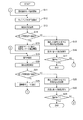
図6はHMD100の動作を示すフローチャートである。
HMD100の電源がオンされた後、制御部140は、通常動作モードで動作を開始する(ステップS11)。
制御部140は、入力検出部162がタッチパッド401、402に対する操作を検出すると(ステップS12)、入力解析部163が操作を解析して操作状態を特定する(ステップS13)。ここで、処理実行部164は、入力解析部163が特定した操作状態が、動作モードの切り替えを指示する操作に該当するか否かを判定する(ステップS14)。
動作モードの切り替えを指示する操作に該当しない場合(ステップS14;NO)、処理実行部164は、設定データ121を参照して、ステップS13で入力解析部163が特定した操作状態に対応する処理に関する設定を取得する(ステップS15)。処理実行部164は、設定された処理を実行し(ステップS16)、その後、制御部140は動作を終了するか否かを判定する(ステップS17)。例えば電源スイッチが操作された場合など動作を終了すると判定した場合(ステップS17;YES)、制御部140は本処理を終了する。また、動作を終了しない場合(ステップS17;NO)、ステップS12に戻る。
FIG. 6 is a flowchart showing the operation of the HMD 100.
After the power of the HMD 100 is turned on, the control unit 140 starts operation in the normal operation mode (step S11).
When the input detection unit 162 detects an operation on the touch pads 401 and 402 (step S12), the control unit 140 analyzes the operation and identifies the operation state (step S13). Here, the process execution unit 164 determines whether or not the operation state specified by the input analysis unit 163 corresponds to an operation instructing switching of the operation mode (step S14).
When the operation does not correspond to the operation instructing the switching of the operation mode (step S14; NO), the process execution unit 164 refers to the setting data 121 and relates to the process corresponding to the operation state specified by the input analysis unit 163 in step S13. A setting is acquired (step S15). The process execution unit 164 executes the set process (step S16), and then the control unit 140 determines whether or not to end the operation (step S17). For example, when it is determined that the operation is to be ended, for example, when the power switch is operated (step S17; YES), the control unit 140 ends this process. Moreover, when not complete | finishing operation | movement (step S17; NO), it returns to step S12.

処理実行部164は、入力解析部163が特定した操作状態が、動作モードの切り替えを指示する操作に該当すると判定した場合(ステップS14;YES)、処理実行部164は、近接操作モードに移行する(ステップS18)。ステップS18では、処理実行部164が外部センサー400に対する操作に応じて処理を実行可能な状態に移行する。具体的には、入力検出部162の制御による外部センサー400の検出動作の開始、或いは、入力解析部163による解析の開始等が行われる。   When the process execution unit 164 determines that the operation state specified by the input analysis unit 163 corresponds to an operation instructing switching of the operation mode (step S14; YES), the process execution unit 164 shifts to the proximity operation mode. (Step S18). In step S <b> 18, the process execution unit 164 shifts to a state where the process can be executed in accordance with an operation on the external sensor 400. Specifically, the detection operation of the external sensor 400 is started by the control of the input detection unit 162, or the analysis is started by the input analysis unit 163.

次いで、入力検出部162が外部センサー400またはタッチパッド401、402に対する操作を検出すると(ステップS19)、入力解析部163が操作を解析して操作状態を特定する(ステップS20)。ここで、処理実行部164は、入力解析部163が特定した操作状態が、動作モードの切り替えを指示する操作に該当するか否かを判定する(ステップS21)。
動作モードの切り替えを指示する操作に該当しない場合(ステップS21;NO)、処理実行部164は、設定データ121を参照して、ステップS20で入力解析部163が特定した操作状態に対応する処理に関する設定を取得する(ステップS22)。処理実行部164は、設定された処理を実行し(ステップS23)、その後、制御部140は動作を終了するか否かを判定する(ステップS24)。動作を終了すると判定した場合(ステップS24;YES)、制御部140は本処理を終了する。また、動作を終了しない場合(ステップS24;NO)、ステップS19に戻る。
Next, when the input detection unit 162 detects an operation on the external sensor 400 or the touch pads 401 and 402 (step S19), the input analysis unit 163 analyzes the operation and specifies the operation state (step S20). Here, the process execution unit 164 determines whether or not the operation state specified by the input analysis unit 163 corresponds to an operation instructing switching of the operation mode (step S21).
When the operation does not correspond to the operation instructing the switching of the operation mode (step S21; NO), the process execution unit 164 refers to the setting data 121 and relates to the process corresponding to the operation state specified by the input analysis unit 163 in step S20. A setting is acquired (step S22). The process execution unit 164 executes the set process (step S23), and then the control unit 140 determines whether to end the operation (step S24). When it determines with complete | finishing operation | movement (step S24; YES), the control part 140 complete | finishes this process. Moreover, when not complete | finishing operation | movement (step S24; NO), it returns to step S19.

処理実行部164は、入力解析部163が特定した操作状態が、動作モードの切り替えを指示する操作に該当すると判定した場合(ステップS21;YES)、処理実行部164は、通常動作モードに移行し(ステップS25)、ステップS12に戻る。   If the process execution unit 164 determines that the operation state specified by the input analysis unit 163 corresponds to an operation instructing switching of the operation mode (step S21; YES), the process execution unit 164 shifts to the normal operation mode. (Step S25), the process returns to Step S12.

動作モードの切り替えを指示する操作は、例えば、タッチパッド401またはタッチパッド402に対するダブルタップ操作である。通常動作モードから近接操作モードへの切り替え、及び、近接操作モードから通常動作モードへの切り替えの両方で、動作モードの切り替えを指示する操作を共通する操作としてもよい。この場合、通常動作モード及び近接操作モードの両方で検出可能な操作とするため、当該操作はタッチパッド401、402に対する操作とすることが好ましい。
また、通常動作モードにおいては、外部センサー400の操作に対応する処理を行わないが、動作モードの切り替えを指示する外部センサー400の操作のみ検出し、動作モードの切り替えを行ってもよい。
The operation for instructing the switching of the operation mode is, for example, a double tap operation on the touch pad 401 or the touch pad 402. An operation for instructing switching of the operation mode may be made common to both the switching from the normal operation mode to the proximity operation mode and the switching from the proximity operation mode to the normal operation mode. In this case, the operation is preferably performed on the touch pads 401 and 402 in order to detect the operation in both the normal operation mode and the proximity operation mode.
In the normal operation mode, processing corresponding to the operation of the external sensor 400 is not performed, but only the operation of the external sensor 400 that instructs switching of the operation mode may be detected and the operation mode may be switched.

ここで、外部センサー400の操作に対応して処理実行部164が表示態様を変化させる動作の具体例について説明する。
図7は、HMD100に対する操作の態様と表示の具体例を示す図である。図7(A)は操作の一例を示し、図7(B)は図7(A)の操作に対応する表示例を示す。また、図7(C)は操作の別の例を示し、図7(D)は図7(C)の操作に対応する表示例を示す。
Here, a specific example of an operation in which the process execution unit 164 changes the display mode corresponding to the operation of the external sensor 400 will be described.
FIG. 7 is a diagram showing a specific example of an operation mode and display on the HMD 100. FIG. 7A shows an example of the operation, and FIG. 7B shows a display example corresponding to the operation of FIG. FIG. 7C shows another example of the operation, and FIG. 7D shows a display example corresponding to the operation of FIG.

図7(A)では、2つの操作体をHMD100の側方において近接させた状態を示し、より具体的には、2つの操作体RH、LHを左右に離隔させた状態で、HMD100に近接させた状態を示す。操作体RHは、例えば使用者の右手であり、操作体LHは使用者の左手である。操作体RH、LHは、HMD100の側方に限らず、右導光部26、左導光部28の前方であってもよい。図7(A)には、理解の便宜のため、HMD100を裏面側、すなわち装着状態における使用者の顔の側から見た図を示す。
図7(A)及び(B)に符号Dで示すように、外部センサー400の検出範囲Dは、右導光部26、左導光部28の前方および上下左右に拡がる空間に位置する。
FIG. 7A shows a state in which two operating bodies are close to each other on the side of the HMD 100. More specifically, the two operating bodies RH and LH are separated from each other in the left and right directions to be close to the HMD 100. Indicates the state. The operating tool RH is, for example, the user's right hand, and the operating tool LH is the user's left hand. The operating bodies RH and LH are not limited to the sides of the HMD 100 and may be in front of the right light guide unit 26 and the left light guide unit 28. For convenience of understanding, FIG. 7A shows a view of the HMD 100 as seen from the back side, that is, the face of the user in the wearing state.
7A and 7B, the detection range D of the external sensor 400 is located in a space that extends in front of the right light guide unit 26 and the left light guide unit 28 and in the vertical and horizontal directions.

図7(A)の操作は、操作体RH、LHを右導光部26、左導光部28のそれぞれに近接させて、上方向U、または下方向Dに動かす操作を示す。この場合、入力解析部163は、外部センサー400の右センサー部410により操作体RHを検出し、左センサー部420により操作体LHを検出する。処理実行部164は、右センサー部410と左センサー部420とがそれぞれ一つの物体を検出した場合に、設定された動作として、位置入力用のY方向ガイドGY(操作制御命令画像)を表示する。図7(B)には使用者の視野VRにおいて、表示領域VAにY方向ガイドGYが表示される。ここで、表示領域VAは右導光部26及び左導光部28が形成する虚像を使用者が視認する最大の範囲を示す。表示領域VAは、実際には、使用者の右眼が視認する虚像と左眼が視認する虚像とが、使用者の視機能により合成された領域であるが、ここでは使用者が視認する像を示す意味で一つの矩形として表現する。   The operation in FIG. 7A indicates an operation in which the operating bodies RH and LH are moved close to the right light guide unit 26 and the left light guide unit 28 and moved in the upward direction U or the downward direction D, respectively. In this case, the input analysis unit 163 detects the operating tool RH by the right sensor unit 410 of the external sensor 400 and detects the operating tool LH by the left sensor unit 420. When the right sensor unit 410 and the left sensor unit 420 each detect one object, the process execution unit 164 displays a Y-direction guide GY (operation control command image) for position input as the set operation. . In FIG. 7B, the Y-direction guide GY is displayed in the display area VA in the visual field VR of the user. Here, the display area VA indicates a maximum range in which the user visually recognizes a virtual image formed by the right light guide unit 26 and the left light guide unit 28. The display area VA is actually an area in which a virtual image visually recognized by the user's right eye and a virtual image visually recognized by the left eye are synthesized by the user's visual function. Here, the image visually recognized by the user is displayed. Is expressed as a single rectangle.

Y方向ガイドGYは、縦方向すなわちY方向における位置を入力する操作を行うためのガイドであり、例えば表示領域VAに横方向に延びる直線である。
処理実行部164は、表示領域VAにY方向ガイドGYを表示させ、入力解析部163が操作体RH及び操作体LHの上方向Uへの移動を検出した場合、この上方向Uの移動に追従するように、Y方向ガイドGYを上方向Uに移動させる。また、入力解析部163が操作体RH及び操作体LHの下方向Dへの移動を検出した場合、この下方向Dの移動に追従するように、Y方向ガイドGYを下方向Dに移動させる。入力解析部163が検出する操作体RH、操作体LHの移動量と、Y方向ガイドGYの移動量との対応は、予め設定データ121に設定される。
The Y direction guide GY is a guide for performing an operation of inputting a position in the vertical direction, that is, the Y direction, and is, for example, a straight line extending in the horizontal direction in the display area VA.
The process execution unit 164 displays the Y direction guide GY in the display area VA, and when the input analysis unit 163 detects the upward movement of the operating body RH and the operating body LH, the process execution section 164 follows the upward movement of the U. Thus, the Y direction guide GY is moved in the upward direction U. When the input analysis unit 163 detects the downward movement D of the operation body RH and the operation body LH, the Y-direction guide GY is moved in the downward direction D so as to follow the movement in the downward direction D. The correspondence between the movement amounts of the operating body RH and the operating body LH detected by the input analysis unit 163 and the movement amount of the Y-direction guide GY is set in the setting data 121 in advance.

図7(A)、(B)に示すように、HMD100では、使用者が右手を右眼側に位置させ、左手を左眼側に位置させてフレーム3に近づけることにより、Y方向の位置入力を行える。Y方向ガイドGYを所望の位置に移動させた後、使用者が操作体RH、LHを所定の態様で動かすと、Y方向の位置が確定される。所定の態様とは、例えば、操作体RH、LHを所定時間静止させる、操作体RH、LHの両方を水平方向すなわちX方向(図7(C)の右方向Rまたは左方向L)に平行移動させる,等が挙げられる。また、操作体RH、LHを上方向Uまたは下方向Dに移動させる間、操作体RH、LHをフレーム3に接触させている場合、操作体RH、LHをフレーム3から離隔させることで、Y方向の位置を確定してもよい。   As shown in FIGS. 7A and 7B, in the HMD 100, the user inputs the position in the Y direction by positioning the right hand on the right eye side and the left hand on the left eye side and approaching the frame 3. Can be done. After the Y-direction guide GY is moved to a desired position, when the user moves the operating bodies RH and LH in a predetermined manner, the position in the Y direction is determined. The predetermined mode is, for example, that the operating bodies RH and LH are stopped for a predetermined time, and both the operating bodies RH and LH are translated in the horizontal direction, that is, the X direction (the right direction R or the left direction L in FIG. 7C). And so on. Further, when the operating bodies RH and LH are in contact with the frame 3 while the operating bodies RH and LH are moved in the upward direction U or the downward direction D, the operating bodies RH and LH are separated from the frame 3 so that Y The position in the direction may be determined.

図7(C)の操作は、操作体RH、LHをフレーム3に近接させて、右方向R、または左方向Lに動かす操作を示す。この場合、入力解析部163は、外部センサー400の右センサー部410により操作体RHを検出し、左センサー部420により操作体LHを検出する。処理実行部164は、図7(A)に示す操作でY方向の位置が確定された後、右センサー部410と左センサー部420とがそれぞれ一つの物体を検出している場合に、設定された動作として、位置入力用のX方向ガイドGX(操作制御命令画像)を表示する。
図7(D)では使用者の視野VRにおいて、表示領域VAにX方向ガイドGXが表示される。X方向ガイドGXは、横方向すなわちX方向における位置を入力する操作を行うためのガイドであり、例えば表示領域VAに縦方向に延びる直線である。
処理実行部164は、表示領域VAにX方向ガイドGXを表示させ、入力解析部163が操作体RH及び操作体LHの右方向Rへの移動を検出した場合、この右方向Rの移動に追従するように、X方向ガイドGXを右方向Rに移動させる。また、入力解析部163が操作体RH及び操作体LHの左方向Lへの移動を検出した場合、この左方向Lの移動に追従するように、X方向ガイドGXを左方向Lに移動させる。入力解析部163が検出する操作体RH、操作体LHの移動量と、X方向ガイドGXの移動量との対応は、予め設定データ121に設定される。
The operation in FIG. 7C indicates an operation in which the operating bodies RH and LH are moved close to the frame 3 and moved in the right direction R or the left direction L. In this case, the input analysis unit 163 detects the operating tool RH by the right sensor unit 410 of the external sensor 400 and detects the operating tool LH by the left sensor unit 420. The process execution unit 164 is set when the right sensor unit 410 and the left sensor unit 420 each detect one object after the position in the Y direction is determined by the operation shown in FIG. As an operation, the X direction guide GX (operation control command image) for position input is displayed.
In FIG. 7D, the X-direction guide GX is displayed in the display area VA in the user's visual field VR. The X direction guide GX is a guide for performing an operation of inputting a position in the horizontal direction, that is, the X direction, and is, for example, a straight line extending in the vertical direction in the display area VA.
The process execution unit 164 displays the X-direction guide GX in the display area VA, and follows the movement in the right direction R when the input analysis unit 163 detects the movement in the right direction R of the operating body RH and the operating body LH. In this way, the X direction guide GX is moved in the right direction R. When the input analysis unit 163 detects the movement of the operating tool RH and the operating tool LH in the left direction L, the X direction guide GX is moved in the left direction L so as to follow the movement in the left direction L. The correspondence between the movement amounts of the operating body RH and the operating body LH detected by the input analysis unit 163 and the movement amount of the X-direction guide GX is set in the setting data 121 in advance.

図7(C)、(D)に示すように、HMD100では、使用者が右手を右眼側に位置させ、左手を左眼側に位置させてフレーム3に近づけることにより、X方向の位置入力を行える。X方向ガイドGXを所望の位置に移動させた後、使用者が操作体RH、LHを所定の態様で動かすと、X方向の位置が確定される。所定の態様とは、Y方向ガイドGYを用いる位置入力と同様、例えば、操作体RH、LHを所定時間静止させる、操作体RH、LHの両方を縦方向すなわちY方向(上方向Uまたは下方向D)に平行移動させる、等が挙げられる。また、操作体RH、LHを右方向Rまたは左方向Lに移動させる間、操作体RH、LHをフレーム3に接触させている場合、操作体RH、LHをフレーム3から離隔させることで、X方向の位置を確定してもよい。   As shown in FIGS. 7C and 7D, in the HMD 100, the user inputs the position in the X direction by positioning the right hand on the right eye side and the left hand on the left eye side and approaching the frame 3. Can be done. After the X-direction guide GX is moved to a desired position, when the user moves the operating bodies RH and LH in a predetermined manner, the position in the X direction is determined. The predetermined mode is similar to the position input using the Y-direction guide GY. For example, the operating bodies RH and LH are stationary for a predetermined time. Both the operating bodies RH and LH are in the vertical direction, that is, the Y direction (upward U or downward). And the like in (D). Further, when the operating bodies RH and LH are in contact with the frame 3 while the operating bodies RH and LH are moved in the right direction R or the left direction L, the operating bodies RH and LH are separated from the frame 3 by moving the operating bodies RH and LH away from the frame 3. The position in the direction may be determined.

図7(A)〜(D)に示す例は、使用者が、視野VRにおける位置を入力または指定する位置入力操作に使用できる。X方向ガイドGX及びY方向ガイドGYの位置により入力された位置は、例えば、入力解析部163が、視野VRにおける位置として検出する。この場合、入力解析部163は、検出した位置を、右LCD241及び左LCD242における表示位置の座標に変換する処理を行ってもよい。
また、Y方向ガイドGY及びX方向ガイドGXを表示させて位置入力を開始するトリガーを、2つの物体の接触を外部センサー400が検出することや、2つの物体の接触を検出した後でいずれか一方の物体の接触が解除されることとしてもよい。つまり、外部センサー400に操作体を接触させる操作と、外部センサー400の検出範囲において操作体を近接させる操作との組み合わせに対応して、処理実行部164が処理を実行してもよい。また、Y方向ガイドGY、X方向ガイドGXを表示する場合に、処理実行部164の制御により、操作方法を案内するテキストや画像を表示してもよい。
The examples shown in FIGS. 7A to 7D can be used for a position input operation in which a user inputs or designates a position in the visual field VR. For example, the input analysis unit 163 detects the position input by the positions of the X direction guide GX and the Y direction guide GY as a position in the visual field VR. In this case, the input analysis unit 163 may perform processing for converting the detected position into the coordinates of the display position on the right LCD 241 and the left LCD 242.
Also, the trigger that starts the position input by displaying the Y-direction guide GY and the X-direction guide GX is either detected by the external sensor 400 detecting the contact between the two objects or after detecting the contact between the two objects. The contact of one object may be released. That is, the process execution unit 164 may execute the process corresponding to a combination of an operation of bringing the operating body into contact with the external sensor 400 and an operation of bringing the operating body close within the detection range of the external sensor 400. Further, when displaying the Y-direction guide GY and the X-direction guide GX, text or an image for guiding the operation method may be displayed under the control of the processing execution unit 164.

また、図7(A)〜(D)に示す操作を、片手で行うことが可能な構成としてもよい。例えば、入力解析部163が、外部センサー400の右センサー部410または左センサー部420のいずれか一方で、2つの位置における接近を検出した場合が挙げられる。この場合、設定された動作として、処理実行部164が、位置入力用のY方向ガイドGY(操作制御命令画像)を表示する。例えば、使用者の右手の人差し指と中指のそれぞれを、操作体として検出する場合に相当する。   Moreover, it is good also as a structure which can perform operation shown to FIG. 7 (A)-(D) with one hand. For example, the input analysis unit 163 may detect the approach at two positions on either the right sensor unit 410 or the left sensor unit 420 of the external sensor 400. In this case, as the set operation, the process execution unit 164 displays a Y-direction guide GY (operation control command image) for position input. For example, this corresponds to a case where each of the index finger and the middle finger of the user's right hand is detected as an operating tool.

処理実行部164は、図7(B)に示すように、Y方向ガイドGYが表示された状態で、2つの操作体(右手の人差し指と中指)を上下(図1のY方向)に動かす操作を検出し、この操作に対応して、Y方向ガイドGYを上下に移動させる。入力解析部163が検出する2つの操作体の移動量と、Y方向ガイドGYの移動量との対応は、予め設定データ121に設定される。そして、入力解析部163が、2つの操作体のいずれかがフレーム3から所定距離以上、離隔したことを検出した場合に、Y方向の位置を確定する。   As shown in FIG. 7B, the processing execution unit 164 moves the two operating bodies (the index finger and the middle finger of the right hand) up and down (Y direction in FIG. 1) while the Y direction guide GY is displayed. And the Y-direction guide GY is moved up and down in response to this operation. The correspondence between the movement amount of the two operating bodies detected by the input analysis unit 163 and the movement amount of the Y-direction guide GY is set in the setting data 121 in advance. When the input analysis unit 163 detects that one of the two operating bodies is separated from the frame 3 by a predetermined distance or more, the position in the Y direction is determined.

さらに、入力解析部163が、外部センサー400の右センサー部410または左センサー部420のいずれか一方で、2つの位置における接近を検出した場合、処理実行部164は、位置入力用のX方向ガイドGX(操作制御命令画像)を表示する。例えば、使用者の右手の人差し指と中指のそれぞれを、操作体として検出する場合に相当する。
処理実行部164は、図7(D)に示すように、X方向ガイドGXが表示された状態で、2つの操作体(右手の人差し指と中指)を左右(図1のZ方向)に動かす操作を検出し、この操作に対応して、X方向ガイドGXを左右に移動させる。入力解析部163が検出する2つの操作体の移動量と、X方向ガイドGXの移動量との対応は、予め設定データ121に設定される。そして、入力解析部163が、2つの操作体のいずれかがフレーム3から所定距離以上、離隔したことを検出した場合に、X方向の位置を確定する。
また、この操作は、2つの操作体を図1のX方向に移動させた場合に、フレーム3を通してみる使用者の視界の奥行き方向における位置入力に適用してもよい。
Furthermore, when the input analysis unit 163 detects an approach at two positions on either the right sensor unit 410 or the left sensor unit 420 of the external sensor 400, the process execution unit 164 detects the X direction guide for position input. GX (operation control command image) is displayed. For example, this corresponds to a case where each of the index finger and the middle finger of the user's right hand is detected as an operating tool.
As shown in FIG. 7D, the processing execution unit 164 moves the two operating bodies (the index finger and the middle finger of the right hand) left and right (the Z direction in FIG. 1) while the X direction guide GX is displayed. In response to this operation, the X-direction guide GX is moved left and right. The correspondence between the movement amounts of the two operating bodies detected by the input analysis unit 163 and the movement amount of the X direction guide GX is set in the setting data 121 in advance. When the input analysis unit 163 detects that one of the two operating bodies is separated from the frame 3 by a predetermined distance or more, the input analysis unit 163 determines the position in the X direction.
Further, this operation may be applied to position input in the depth direction of the user's field of view viewed through the frame 3 when the two operating bodies are moved in the X direction of FIG.

図8は、HMD100に対する操作の態様と表示の具体例を示す図である。図8(A)は操作の一例を示し、図8(B)、(C)は図8(A)の操作に対応する表示例を示す。   FIG. 8 is a diagram showing a specific example of an operation mode and display for the HMD 100. FIG. 8A shows an example of the operation, and FIGS. 8B and 8C show display examples corresponding to the operation of FIG. 8A.

図8(A)では、2つの操作体をHMD100の前方において近接させた状態を示し、より具体的には、2つの操作体RH、LHを左右に離隔させた状態で、右導光部26、左導光部28の前面に近接させた状態を示す。図8(A)の例では、操作体RHはセンサー413に近接し、操作体LHはセンサー423に近接する。図8(A)には、理解の便宜のため、HMD100を表面側、すなわち装着状態における使用者の顔を外から見た図を示す。
図8(A)に符号Dで示すように、外部センサー400の検出範囲Dは、右導光部26、左導光部28の前方および上下左右に拡がる空間に位置する。
FIG. 8A shows a state in which two operating bodies are brought close to each other in front of the HMD 100, and more specifically, the right light guide unit 26 in a state in which the two operating bodies RH and LH are separated from each other on the left and right. The state which was made to adjoin to the front surface of the left light guide part 28 is shown. In the example of FIG. 8A, the operating tool RH is close to the sensor 413, and the operating tool LH is close to the sensor 423. For convenience of understanding, FIG. 8A shows a view of the HMD 100 as viewed from the outside, that is, the user's face in the wearing state.
8A, the detection range D of the external sensor 400 is located in a space extending in front of the right light guide unit 26 and the left light guide unit 28, and in the vertical and horizontal directions.

図8(A)の操作は、操作体RHをセンサー413に沿って移動させ、操作体LHをセンサー423に沿って移動させる操作を示す。この場合、入力解析部163は、右センサー部410のセンサー413により操作体RH及びその移動を検出し、左センサー部420のセンサー423により操作体LH及びその移動を検出する。   The operation of FIG. 8A shows an operation of moving the operating tool RH along the sensor 413 and moving the operating tool LH along the sensor 423. In this case, the input analysis unit 163 detects the operating body RH and its movement by the sensor 413 of the right sensor unit 410, and detects the operating body LH and its movement by the sensor 423 of the left sensor unit 420.

処理実行部164は、外部センサー400が備えるセンサー(本実施形態では6個)により、2つの物体を検出し、2つの物体が接近或いは離隔する操作を検出した場合に、設定された動作として、表示の拡大または縮小を行う。
図8(B)、(C)には使用者の視野VRにおいて、表示画像V1が表示される。処理実行部164は、入力解析部163が外部センサー400の操作として、2つの物体が離隔する操作を検出した場合に、表示中の画像を拡大する。例えば、処理実行部164は、図8(C)の表示状態から表示画像V1の表示倍率を変更し、図8(B)の表示状態に移行させる。また、処理実行部164は、入力解析部163が外部センサー400の操作として、2つの物体が接近隔する操作を検出した場合に、表示中の画像を縮小する。例えば、処理実行部164は、図8(B)の表示状態から表示画像V1の表示倍率を変更し、図8(C)の表示状態に移行させる。
The process execution unit 164 detects two objects with the sensors (six in this embodiment) included in the external sensor 400, and detects an operation in which the two objects approach or separate from each other. Enlarge or reduce the display.
8B and 8C, the display image V1 is displayed in the visual field VR of the user. When the input analysis unit 163 detects an operation of separating two objects as an operation of the external sensor 400, the processing execution unit 164 enlarges the displayed image. For example, the process execution unit 164 changes the display magnification of the display image V1 from the display state of FIG. 8C, and shifts to the display state of FIG. In addition, the processing execution unit 164 reduces the displayed image when the input analysis unit 163 detects an operation in which two objects approach each other as an operation of the external sensor 400. For example, the process execution unit 164 changes the display magnification of the display image V1 from the display state of FIG. 8B, and shifts to the display state of FIG.

外部センサー400において検出される2つの物体の距離の変化量と、表示画像V1の表示倍率または表示サイズの変化量との対応は、予め設定データ121に設定される。   The correspondence between the change amount of the distance between the two objects detected by the external sensor 400 and the change amount of the display magnification or display size of the display image V1 is set in the setting data 121 in advance.

図8(A)〜(C)に示すように、HMD100では、使用者が手をフレーム3に接近させて、少なくとも2つの物体として検出させ、この2つの物体を接近または離隔させる操作を行うことで、表示画像V1の表示サイズを変更できる。この操作は、物体を一つのセンサーが検出し続ける場合に限定されない。例えば、物体がセンサー411、412、413に跨がって検出されてもよく、この場合、入力解析部163は、隣接するセンサーで連続して物体を検出する検出値を解析して、一つの物体が異なるセンサーに跨がって移動した操作を検出できればよい。また、2つの物体を、右センサー部410と左センサー部420とがそれぞれ一つずつ検出することを条件にしてもよいし、物体を検出するセンサーについて条件を設けなくてもよい。例えば、入力解析部163が1つのセンサーにより2つの物体を検出可能な構成である場合、1つのセンサーが検出する2つの物体について接近、離隔を検出してもよい。従って、例えば、使用者の一方の手を用い、2本の指をフレーム3に近接させ、これら2本の指を接近または離隔させる操作によって表示領域VAの表示サイズを変更させてもよい。   As shown in FIGS. 8A to 8C, in the HMD 100, the user moves the hand close to the frame 3 to detect it as at least two objects, and performs an operation of approaching or separating the two objects. Thus, the display size of the display image V1 can be changed. This operation is not limited to the case where one sensor continues to detect an object. For example, the object may be detected across the sensors 411, 412, and 413. In this case, the input analysis unit 163 analyzes the detection value for detecting the object continuously by the adjacent sensor, It is only necessary to detect an operation in which an object moves across different sensors. In addition, it may be a condition that the right sensor unit 410 and the left sensor unit 420 respectively detect two objects one by one, or a condition may not be provided for a sensor that detects an object. For example, when the input analysis unit 163 has a configuration in which two objects can be detected by one sensor, approach and separation may be detected for two objects detected by one sensor. Therefore, for example, the display size of the display area VA may be changed by an operation of using one hand of the user to bring two fingers close to the frame 3 and approach or separate the two fingers.

また、図8(A)に示すように外部センサー400が2つの操作体を検出した場合、これら2つの操作体の回転操作に対応して、表示画像V1を回転させてもよい。この場合、入力解析部163は、2つの操作体の検出位置が相対的に移動し、一方の検出位置の動きが他方の検出位置の動きより大きい場合に、回転したと判定してもよい。表示画像V1を回転させる回転角度は、操作体の回転の度合いまたは回転スピードに従って決めてもよい。また、例えば、操作位置がほぼ移動せず、操作体が複数回回転した場合に、回転数により回転角度を決めても良い。   In addition, as shown in FIG. 8A, when the external sensor 400 detects two operating bodies, the display image V1 may be rotated in response to the rotating operation of these two operating bodies. In this case, the input analysis unit 163 may determine that the detection position of the two operating bodies has moved relatively and the rotation of one detection position is larger than the movement of the other detection position. The rotation angle for rotating the display image V1 may be determined according to the degree of rotation or the rotation speed of the operating tool. Further, for example, when the operation position does not substantially move and the operation body rotates a plurality of times, the rotation angle may be determined by the number of rotations.

そのほか、表示領域VAの表示画像V1に対する操作として、次の例が挙げられる。
1.拡大/縮小回転:外部センサー400に2点で接触または近接を検出させ、フレーム3に対し右回転させながらいずれか1点を右センサー部410のいずれかのセンサーに接触させる。ここで、さらに別の1点でいずれかのセンサーに接触または近接を検出させる。この操作に対応して、処理実行部164は、表示画像V1を拡大させながら回転させる。上記操作で左回転させることで表示画像V1を縮小しながら回転させる動作を行ってもよい。
2.拡大/縮小回転:外部センサー400に2点で接触または近接を検出させて表示画像V1を拡大/縮小させる場合に、視野VRの外側に他の操作体を位置させ、この操作体の回転の角度または速度に応じた回転量で表示画像V1を回転させる。
3.外部センサー400の検出範囲において、操作体を外部センサー400に接近させる操作に応じて、表示画像V1を拡大し、操作体Hを外部センサー400から離隔させる操作に応じて、表示画像V1を縮小してもよい。操作体を外部センサー400に接近または離隔させる操作を、他の操作体を外部センサー400のセンサーに接触させる操作と組み合わせてもよい。
In addition, the following example is given as an operation for the display image V1 in the display area VA.
1. Enlargement / reduction rotation: The external sensor 400 detects contact or proximity at two points, and makes any one point contact any sensor of the right sensor unit 410 while rotating the frame 3 to the right. Here, contact or proximity is detected by any one of the sensors at another point. In response to this operation, the process execution unit 164 rotates the display image V1 while enlarging it. An operation of rotating the display image V1 while reducing it may be performed by rotating it to the left by the above operation.
2. Enlargement / reduction rotation: When the external sensor 400 detects contact or proximity at two points to enlarge / reduce the display image V1, another operation body is positioned outside the visual field VR, and the rotation angle of this operation body Alternatively, the display image V1 is rotated by a rotation amount corresponding to the speed.
3. In the detection range of the external sensor 400, the display image V1 is enlarged according to an operation of bringing the operating body close to the external sensor 400, and the display image V1 is reduced according to an operation of moving the operating body H away from the external sensor 400. May be. An operation of causing the operating body to approach or separate from the external sensor 400 may be combined with an operation of bringing another operating body into contact with the sensor of the external sensor 400.

図9は、HMD100に対する操作の態様と表示の別の具体例を示す図である。図9(A)、(B)は仮想キーボードVKBを用いた入力操作の例を示す。   FIG. 9 is a diagram illustrating another specific example of the mode of operation and display on the HMD 100. 9A and 9B show examples of input operations using the virtual keyboard VKB.

図9(A)、(B)では、外部センサー400またはタッチパッド401、402の操作により、仮想キーボードVKBが呼び出された状態を示す。仮想キーボードVKBは、複数の入力キーを含むキーボード形状の画像であり、画像表示部20が表示領域VAに表示する。使用者が、仮想キーボードVKBが表示され視認可能な状態で、表示領域VAにおける位置入力操作を行うと、入力された位置にポインターVPが表示される。ここで、使用者により確定操作が行われると、ポインターVPに重なる位置のキーが選択され、文字が入力される。ポインターVPの位置を指定する操作は、例えば、図7(A)〜(C)を参照して説明した位置入力操作を採用できる。   FIGS. 9A and 9B show a state in which the virtual keyboard VKB is called by the operation of the external sensor 400 or the touch pads 401 and 402. FIG. The virtual keyboard VKB is a keyboard-shaped image including a plurality of input keys, and is displayed on the display area VA by the image display unit 20. When the user performs a position input operation in the display area VA while the virtual keyboard VKB is displayed and visible, the pointer VP is displayed at the input position. Here, when the confirmation operation is performed by the user, a key at a position overlapping the pointer VP is selected, and a character is input. For example, the position input operation described with reference to FIGS. 7A to 7C can be adopted as the operation for designating the position of the pointer VP.

図9(B)には、仮想キーボードVKBとともにアプリケーション画面VAPを表示した例を示す。アプリケーション画面VAPは、制御部140が実行するアプリケーションプログラムにより、例えば文書編集を行う画面である。アプリケーション画面VAPはアプリケーションプログラムで使用者が実行する処理に対応する画面である。アプリケーションプログラムがGUIによる操作を可能とする場合、例えば、アイコン配置部IAに配置されたアイコンを選択する操作が行われる。   FIG. 9B shows an example in which the application screen VAP is displayed together with the virtual keyboard VKB. The application screen VAP is a screen on which, for example, document editing is performed by an application program executed by the control unit 140. The application screen VAP is a screen corresponding to processing executed by the user in the application program. When the application program enables an operation using the GUI, for example, an operation of selecting an icon arranged in the icon arrangement unit IA is performed.

図9(B)の例では、仮想キーボードVKBのキーを選択する操作、及び、アプリケーション画面VAPのアイコン配置部IAに配置されたアイコンを選択する操作が行われる。これらはいずれも位置入力操作を利用できる。また、仮想キーボードVKBを操作する第1状態と、アプリケーション画面VAPを操作する第2状態とを、外部センサー400を利用した操作により切り替えさせることができる。
例えば、使用者の手等の操作体により、右センサー部410または左センサー部420を覆う操作により、第1状態と第2状態とを切り替えてもよい。この場合、入力解析部163は、右センサー部410の各センサーがほぼ同時に物体を検出した検出値、又は、左センサー部420の各センサーがほぼ同時に物体を検出した検出値に基づき、右センサー部410又は左センサー部420を覆う操作を検出する。また、タッチパッド401、402に対するダブルタップの操作で第1状態と第2状態とを切り替えてもよい。
In the example of FIG. 9B, an operation of selecting a key of the virtual keyboard VKB and an operation of selecting an icon arranged in the icon arrangement unit IA of the application screen VAP are performed. Any of these can use a position input operation. In addition, the first state in which the virtual keyboard VKB is operated and the second state in which the application screen VAP is operated can be switched by an operation using the external sensor 400.
For example, the first state and the second state may be switched by an operation of covering the right sensor unit 410 or the left sensor unit 420 with an operation body such as a user's hand. In this case, the input analysis unit 163 detects the right sensor unit based on the detection value that each sensor of the right sensor unit 410 detects an object almost simultaneously or the detection value that each sensor of the left sensor unit 420 detects an object almost simultaneously. An operation covering 410 or the left sensor unit 420 is detected. Further, the first state and the second state may be switched by a double tap operation on the touch pads 401 and 402.

図9(A)、(B)に示す例において、図8(A)〜(C)を参照して説明した操作により、処理実行部164は、仮想キーボードVKBの表示サイズを拡大、或いは縮小してもよい。また、仮想キーボードVKBを回転させる処理や、仮想キーボードVKBにおけるキー配列の変更、キーボードの種類(日本語キーボード、英語キーボード、テンキーなど)の変更等を行ってもよい。
また、図9(A)で仮想キーボードVKBを使用して文字入力が行われた後、入力された文字または文字列を、アプリケーションプログラムに転送して処理してもよい。転送するアプリケーションプログラムの選択や転送実行の指示をする操作として、外部センサー400に操作体を接近させる操作、外部センサー400の検出範囲内において操作体を所定の態様で動かす操作等が挙げられる。
また、仮想キーボードVKBの表示開始時、仮想キーボードVKBとアプリケーション画面VAPの表示時または切り替え時に、操作を案内する画像やテキストを、ポップアップ表示またはバルーン表示してもよい。
In the example shown in FIGS. 9A and 9B, the processing execution unit 164 enlarges or reduces the display size of the virtual keyboard VKB by the operation described with reference to FIGS. 8A to 8C. May be. Further, a process of rotating the virtual keyboard VKB, a change in the key layout in the virtual keyboard VKB, a change in the keyboard type (Japanese keyboard, English keyboard, numeric keypad, etc.), and the like may be performed.
In addition, after a character is input using the virtual keyboard VKB in FIG. 9A, the input character or character string may be transferred to the application program for processing. Examples of operations for selecting an application program to be transferred and instructing transfer execution include an operation for bringing the operating body close to the external sensor 400, an operation for moving the operating body in a predetermined manner within the detection range of the external sensor 400, and the like.
Further, when displaying the virtual keyboard VKB, when displaying or switching the virtual keyboard VKB and the application screen VAP, an image or text for guiding the operation may be displayed in a pop-up or balloon display.

図10は、HMD100に対する操作の態様と表示の別の具体例を示す図であり、仮想リモートコントローラーVRCを用いた入力操作の例を示す。   FIG. 10 is a diagram showing another specific example of the mode of operation and display on the HMD 100, and shows an example of an input operation using the virtual remote controller VRC.

図10では、外部センサー400またはタッチパッド401、402の操作により、仮想リモートコントローラーVRCが呼び出された状態を示す。仮想リモートコントローラーVRCは、複数の入力キーを含み、家庭用電化製品やAV(Audio Visual)機器を操作するリモートコントローラーを模した画像である。仮想リモートコントローラーVRCは、実空間のリモートコントローラーと同様に複数の操作用スイッチが配置される。仮想リモートコントローラーVRCが表示された状態で、上記の位置入力操作により、仮想リモートコントローラーVRCの操作用スイッチを選択することができる。   FIG. 10 shows a state in which the virtual remote controller VRC is called by the operation of the external sensor 400 or the touch pads 401 and 402. The virtual remote controller VRC is an image that imitates a remote controller that includes a plurality of input keys and operates home appliances and AV (Audio Visual) devices. The virtual remote controller VRC is provided with a plurality of operation switches in the same manner as the real space remote controller. With the virtual remote controller VRC displayed, the operation switch of the virtual remote controller VRC can be selected by the position input operation described above.

また、上述した表示画像V1の拡大/縮小を指示する操作により、仮想リモートコントローラーVRCの表示サイズを拡大/縮小できる。また、上述した表示画像V1の回転を指示する操作により、仮想リモートコントローラーVRCの表示角度の変更すなわち回転を行える。   Further, the display size of the virtual remote controller VRC can be enlarged / reduced by the operation for instructing the enlargement / reduction of the display image V1 described above. Further, the display angle of the virtual remote controller VRC can be changed, that is, rotated by the operation for instructing the rotation of the display image V1 described above.

また、図10には方向指示ガイドVAGが表示される。方向指示ガイドVAGは、上下左右に対応する4つの方向指示の操作を行うための画像である。方向指示ガイドVAGに対する上記の位置入力操作により、上下左右のいずれかの方法を指示できる。   In addition, a direction instruction guide VAG is displayed in FIG. The direction instruction guide VAG is an image for performing four direction instruction operations corresponding to up, down, left, and right. By the above-described position input operation with respect to the direction instruction guide VAG, any one of up, down, left and right methods can be instructed.

図10の状態では、位置入力操作により指示される位置に、円形のポインターVPが表示され、仮想リモートコントローラーVRC、及び、方向指示ガイドVAGに対する位置入力操作をガイドする。   In the state of FIG. 10, a circular pointer VP is displayed at a position indicated by the position input operation, and guides the position input operation for the virtual remote controller VRC and the direction indication guide VAG.

仮想リモートコントローラーVRC、及び、方向指示ガイドVAGは、上述した仮想キーボードVKBを表示させる操作と同様の操作により、或いは後述するメニュー操作により、表示を開始させることができる。
仮想リモートコントローラーVRCの操作用スイッチを位置入力操作によって選択すると、処理実行部164は、通信部117を制御して、仮想リモートコントローラーVRCが操作対象とする外部の機器に信号を送信する。操作対象の外部の機器は、例えば、上述したように家庭用電化製品やAV機器であるが、無線信号により制御または操作可能な装置であれば限定されない。また、通信部117は、処理実行部164の制御に従って、無線LAN、Bluetooth等の無線信号を送信してもよい。また、通信部117が、赤外線信号を送信するIR送信機(図示略)を備える場合、処理実行部164の制御により、通信部117が操作対象の機器に赤外線信号を送信してもよい。
Display of the virtual remote controller VRC and the direction indication guide VAG can be started by an operation similar to the operation of displaying the virtual keyboard VKB described above or by a menu operation described later.
When the operation switch of the virtual remote controller VRC is selected by a position input operation, the process execution unit 164 controls the communication unit 117 to transmit a signal to an external device that is the operation target of the virtual remote controller VRC. The external device to be operated is, for example, a household appliance or an AV device as described above, but is not limited as long as the device can be controlled or operated by a wireless signal. In addition, the communication unit 117 may transmit a wireless signal such as a wireless LAN or Bluetooth according to the control of the processing execution unit 164. When the communication unit 117 includes an IR transmitter (not shown) that transmits an infrared signal, the communication unit 117 may transmit the infrared signal to the operation target device under the control of the processing execution unit 164.

また、HMD100においては、カメラ61により使用者の視線方向を撮像できる。この場合、カメラ61による撮像実行を、外部センサー400を用いた操作で指示できる。
具体的には、外部センサー400に操作体を所定時間以上接触させる操作、或いは、右センサー部410又は左センサー部420を覆う操作に応じて、処理実行部164は、カメラ61のフォーカス調整を指示する。入力解析部163は、外部センサー400が備える所定数以上のセンサーがほぼ同時に接触または近接を検出した場合に、右センサー部410または左センサー部420を覆う操作を検出すればよい。この操作の後で、同様の操作が行われた場合に、カメラ61のシャッター(撮影実行)を行ってもよい。また、表示画像V1を拡大、縮小する上記の操作により、カメラ61のズーム調整を行ってもよい。
In the HMD 100, the camera 61 can capture the user's line-of-sight direction. In this case, execution of imaging by the camera 61 can be instructed by an operation using the external sensor 400.
Specifically, the process execution unit 164 instructs the camera 61 to adjust the focus in response to an operation of bringing the operating body into contact with the external sensor 400 for a predetermined time or an operation of covering the right sensor unit 410 or the left sensor unit 420. To do. The input analysis unit 163 may detect an operation covering the right sensor unit 410 or the left sensor unit 420 when a predetermined number or more of the sensors included in the external sensor 400 detect contact or proximity almost simultaneously. If a similar operation is performed after this operation, the shutter (shooting execution) of the camera 61 may be performed. Further, the zoom adjustment of the camera 61 may be performed by the above-described operation for enlarging or reducing the display image V1.

図11は、HMDに対する操作の態様と表示の具体例を示す図であり、特に、Z方向における操作を利用する例を示す。図11(A)は使用者の視野VRを示し、図11(B)は表示領域VAに表示される操作ガイド領域GAを特に示す。図11(A)の操作ガイド領域GAを含む画面は、操作用画面、及び、案内画面に相当し、操作ガイド領域GAは特に案内画面に対応する。   FIG. 11 is a diagram showing a specific example of the mode of operation and display for the HMD, and particularly shows an example in which an operation in the Z direction is used. FIG. 11A shows the user's visual field VR, and FIG. 11B particularly shows the operation guide area GA displayed in the display area VA. The screen including the operation guide area GA in FIG. 11A corresponds to an operation screen and a guidance screen, and the operation guide area GA particularly corresponds to the guidance screen.

図11(A)の例では、視野VRに、操作をガイドする表示を行う操作ガイド領域GAが配置される。操作ガイド領域GAは、操作アイコンA1〜A4、メニューボタンB1、メニューリストB2、ガイド表示B3等を表示する領域である。これら操作アイコンA1〜A4、メニューボタンB1、メニューリストB2、ガイド表示B3等は、操作制御命令画像に対応する。また、操作ガイド領域GAは、それ自体を使用者が視認可能なように、色付きの領域、或いは枠線を有する領域として、表示領域VAに配置される。メニューリストB2はメニュー画面に相当する。   In the example of FIG. 11A, an operation guide area GA for performing display for guiding operations is arranged in the visual field VR. The operation guide area GA is an area for displaying operation icons A1 to A4, a menu button B1, a menu list B2, a guide display B3, and the like. These operation icons A1 to A4, menu button B1, menu list B2, guide display B3, and the like correspond to operation control command images. Further, the operation guide area GA is arranged in the display area VA as a colored area or an area having a frame line so that the user can visually recognize the operation guide area GA. Menu list B2 corresponds to a menu screen.

図11(B)に操作ガイド領域GAを示す。図11(B)に例示する操作ガイド領域GAは、上端部US、下端部GS、右端部RS、及び左端部LSの4つの辺を有する矩形である。また、上端部US、下端部GS、右端部RS、及び左端部LSは、それぞれ台形となっており、奥行き感のある画像を構成する。使用者には、視界(視野)の奥(前方)に向かって延びる矩形の枠のように見える。操作ガイド領域GAは、表示制御部190が右表示駆動部22と左表示駆動部24とによって視差を有する画像を表示することで、立体画像として表示してもよい。また、平面画像として、図11(B)に示すように上端部US、下端部GS、右端部RS、及び左端部LSを台形にして奥行き感を有する画像として表示してもよい。   FIG. 11B shows the operation guide area GA. The operation guide area GA illustrated in FIG. 11B is a rectangle having four sides: an upper end US, a lower end GS, a right end RS, and a left end LS. Further, the upper end portion US, the lower end portion GS, the right end portion RS, and the left end portion LS each have a trapezoidal shape and form an image with a sense of depth. To the user, it looks like a rectangular frame extending toward the back (front) of the field of view (field of view). The operation guide area GA may be displayed as a stereoscopic image by the display control unit 190 displaying an image having parallax with the right display driving unit 22 and the left display driving unit 24. Further, as a planar image, as shown in FIG. 11B, the upper end US, the lower end GS, the right end RS, and the left end LS may be displayed as a trapezoidal image having a sense of depth.

操作ガイド領域GAにおいて、奥行き方向で移動するように見える向きを、図11(B)にZ方向として示す。また、操作ガイド領域GAにおいて横方向を、X方向とし、操作ガイド領域GAにおいて縦方向をY方向とする。   In the operation guide area GA, the direction that appears to move in the depth direction is shown as the Z direction in FIG. In the operation guide area GA, the horizontal direction is the X direction, and in the operation guide area GA, the vertical direction is the Y direction.

図11(A)に示すように、操作ガイド領域GAには、操作アイコンA1〜A4が表示される。操作アイコンA1〜A4は操作ガイド領域GAの四隅に配置され、外部センサー400の四隅に対する操作に対応する。   As shown in FIG. 11A, operation icons A1 to A4 are displayed in the operation guide area GA. The operation icons A1 to A4 are arranged at the four corners of the operation guide area GA and correspond to operations on the four corners of the external sensor 400.

例えば、操作ガイド領域GAの右下隅に表示される操作アイコンA1、A2は、外部センサー400の検出範囲の右下隅に対応する。外部センサー400の検出範囲の右下隅に操作体を接触または近接する操作が、操作アイコンA1、A2を選択する操作として検出される。操作アイコンA1、A2は、その後の操作体の移動に伴って、X、Y、Z方向に移動する。使用者の片手の2本の指で操作アイコンA1、A2を操作する態様も可能である。
また、操作アイコンA3は外部センサー400の検出領域の左下隅に対応する。外部センサー400の検出範囲の左下隅に操作体を接触または近接する操作が、操作アイコンA3を選択する操作として検出される。操作アイコンA3は、その後の操作体の移動に伴って、X、Y、Z方向に移動する。
操作アイコンA4、A5は外部センサー400の検出領域の右上隅に対応する。外部センサー400の検出範囲の左右上隅に操作体を接触または近接する操作が、操作アイコンA4、A5を選択する操作として検出される。操作アイコンA4、A5は、その後の操作体の移動に伴って、X、Y、Z方向に移動する。使用者の片手の2本の指で操作アイコンA4、A5を操作する態様も可能である。
また、ガイド表示B3は、例えば確定指示を行うアイコンであり、外部センサー400の検出領域の左下隅に対応する。外部センサー400の検出範囲の左下隅に操作体を接触または近接する操作が、ガイド表示B3を選択する操作として検出される。
For example, the operation icons A 1 and A 2 displayed in the lower right corner of the operation guide area GA correspond to the lower right corner of the detection range of the external sensor 400. An operation of bringing the operating body into contact with or approaching the lower right corner of the detection range of the external sensor 400 is detected as an operation of selecting the operation icons A1 and A2. The operation icons A1 and A2 move in the X, Y, and Z directions with the subsequent movement of the operation body. A mode in which the operation icons A1 and A2 are operated with two fingers of one hand of the user is also possible.
The operation icon A3 corresponds to the lower left corner of the detection area of the external sensor 400. An operation of bringing the operating body into contact with or approaching the lower left corner of the detection range of the external sensor 400 is detected as an operation of selecting the operation icon A3. The operation icon A3 moves in the X, Y, and Z directions with the subsequent movement of the operation body.
The operation icons A4 and A5 correspond to the upper right corner of the detection area of the external sensor 400. An operation of bringing the operating body into contact with or close to the upper left and right corners of the detection range of the external sensor 400 is detected as an operation of selecting the operation icons A4 and A5. The operation icons A4 and A5 move in the X, Y, and Z directions with the subsequent movement of the operation body. A mode in which the operation icons A4 and A5 are operated with two fingers of one hand of the user is also possible.
The guide display B3 is, for example, an icon for performing a confirmation instruction, and corresponds to the lower left corner of the detection area of the external sensor 400. An operation of bringing the operating body into contact with or approaching the lower left corner of the detection range of the external sensor 400 is detected as an operation of selecting the guide display B3.

メニューリストB2は、メニューボタンB1の操作により表示されるリストであり、設定項目等のリストである。メニューリストB2に表示される項目は上述した位置入力操作により指定できる。   The menu list B2 is a list displayed by operating the menu button B1, and is a list of setting items and the like. Items displayed in the menu list B2 can be specified by the position input operation described above.

本実施形態では、外部センサー400が物体を検出する検出範囲は、図7(A)、(B)及び図8(A)に符号Dで示したように、右導光部26、左導光部28の前方及び周囲に拡がる空間である。表示領域VAに表示される操作ガイド領域GAは、検出範囲Dに対応する。従って、操作ガイド領域GAの右半分は、検出範囲Dの右半分に対応付けられ、操作ガイド領域GAの左半分は検出範囲Dの左半分に対応付けられる。検出範囲Dの右半分における物体の検出は、実際は右センサー部410のセンサー411、412、413により行われる。また、検出範囲Dの左半分における物体の検出は、左センサー部420のセンサー421、422、423により行われる。つまり、操作ガイド領域GAの右半分は右センサー部410の検出結果に対応付けられ、操作ガイド領域GAの左半分は左センサー部420に対応付けられる。   In the present embodiment, the detection range in which the external sensor 400 detects an object is the right light guide unit 26, the left light guide, as indicated by reference numeral D in FIGS. 7A, 7B, and 8A. This is a space extending in front of and around the portion 28. The operation guide area GA displayed in the display area VA corresponds to the detection range D. Accordingly, the right half of the operation guide area GA is associated with the right half of the detection range D, and the left half of the operation guide area GA is associated with the left half of the detection range D. The detection of the object in the right half of the detection range D is actually performed by the sensors 411, 412, and 413 of the right sensor unit 410. Further, the detection of the object in the left half of the detection range D is performed by the sensors 421, 422, and 423 of the left sensor unit 420. That is, the right half of the operation guide area GA is associated with the detection result of the right sensor unit 410, and the left half of the operation guide area GA is associated with the left sensor unit 420.

上述したように表示領域VAは右導光部26と左導光部28により使用者の両眼に視認させる画像を、使用者の視機能により合成して認識される。従って、右導光部26において、操作ガイド領域GAの左半分は、右導光部26が表示する画像の左半分に位置するが、左センサー部420に対応付けられる。同様に、左導光部28において、操作ガイド領域GAの右半分は左導光部28が表示する画像の右半分に位置するが、右センサー部410に対応付けられる。このように、操作ガイド領域GAは、使用者が意識する検出範囲Dに対応するように、外部センサー400の全体と位置関係が対応付けられている。従って、使用者はフレーム3の全体を、操作体を近接および接触させる範囲として意識し、操作ガイド領域GAに表示される操作アイコンA1〜A5、メニューボタンB1、ガイド表示B3等に対する直感的な操作が可能である。   As described above, the display area VA is recognized by synthesizing an image to be visually recognized by the user's eyes by the right light guide unit 26 and the left light guide unit 28 by the user's visual function. Accordingly, in the right light guide unit 26, the left half of the operation guide area GA is located in the left half of the image displayed by the right light guide unit 26, but is associated with the left sensor unit 420. Similarly, in the left light guide 28, the right half of the operation guide area GA is located in the right half of the image displayed by the left light guide 28, but is associated with the right sensor 410. As described above, the operation guide area GA is associated with the entire external sensor 400 in a positional relationship so as to correspond to the detection range D that the user is aware of. Accordingly, the user is aware of the entire frame 3 as a range in which the operating body is brought close to and in contact with the operation body, and intuitively operates the operation icons A1 to A5, the menu button B1, the guide display B3, and the like displayed in the operation guide area GA. Is possible.

また、図11(A)に示す表示中、HMD100は、通常動作モードを実行して、操作アイコンA1〜A5、メニューボタンB1、メニューリストB2、ガイド表示B3に対する操作を行うことができる。操作ガイド領域GAの表示中に、タッチパッド401、402の操作により、表示領域VAにおける位置指定操作を行い、操作アイコンA1〜A5、メニューボタンB1、メニューリストB2、ガイド表示B3を選択できる。この選択の操作の後に、タッチパッド401、402において、タップ操作や押圧操作を行うことで、選択を確定できる。   In addition, during the display shown in FIG. 11A, the HMD 100 can execute the normal operation mode and perform operations on the operation icons A1 to A5, the menu button B1, the menu list B2, and the guide display B3. While the operation guide area GA is displayed, a position designation operation in the display area VA can be performed by operating the touch pads 401 and 402, and the operation icons A1 to A5, the menu button B1, the menu list B2, and the guide display B3 can be selected. After this selection operation, the selection can be confirmed by performing a tap operation or a pressing operation on the touch pads 401 and 402.

上記実施形態において、近接操作モードにおける外部センサー400の検出範囲の大きさ、或いは広さを、処理実行部164が表示する画像すなわちユーザーインターフェイスの態様により切り替えてもよい。センサーの検出範囲の大きさは、例えば、接触、近接、中近接の3段階に切り替えてもよい。例えば、図7(B)、(D)の表示状態では検出範囲を中近接とし、図8(B)〜(C)に示す表示状態では検出範囲を接触とし、図9〜図11に示す表示状態では検出範囲を近接としてもよい。例えば、検出範囲が接触に設定された場合、入力検出部162は各センサーへの接触を検出し、近接に設定された場合は検出範囲をセンサー表面から2cm以内とし、中近接に設定された場合は検出範囲をセンサー表面から5cm以内としてもよい。また、近接および中近接に設定された状態で、センサー表面に接触する操作と、接触しない操作とを入力検出部162が区別する構成としてもよい。   In the above embodiment, the size or width of the detection range of the external sensor 400 in the proximity operation mode may be switched according to the image displayed by the processing execution unit 164, that is, the user interface mode. The size of the detection range of the sensor may be switched to, for example, three stages of contact, proximity, and medium proximity. For example, in the display states shown in FIGS. 7B and 7D, the detection range is set to the middle proximity, and in the display states shown in FIGS. 8B to 8C, the detection range is set to contact, and the display shown in FIGS. In the state, the detection range may be close. For example, when the detection range is set to contact, the input detection unit 162 detects contact with each sensor. When the detection range is set to proximity, the detection range is within 2 cm from the sensor surface, and is set to medium proximity. The detection range may be within 5 cm from the sensor surface. Moreover, it is good also as a structure which the input detection part 162 distinguishes the operation which contacts a sensor surface, and the operation which does not contact in the state set to proximity | contact and middle proximity | contact.

以上説明したように、本発明を適用した第1実施形態に係るHMD100は、使用者の頭部に装着された状態で、使用者が実空間を視認可能に画像を表示する表示部としての右導光部26、左導光部28、或いは画像表示部20を備える。HMD100は、右導光部26、左導光部28周辺への操作体の接近を検出する外部センサー400と、操作を受け付けるタッチパッド401、402とを備える。制御部140は、外部センサー400が検出する操作体の動きにより、右導光部26、左導光部28が表示する表示と操作体の動きに対応する操作とを対応させる。
このHMD100の構成、及び、HMD100の制御方法によれば、使用者は、フレーム3に接触することなく容易にHMD100を操作でき、例えば作業中に操作を行う場合等の利便性の向上を図ることができる。
As described above, the HMD 100 according to the first embodiment to which the present invention is applied is the right as a display unit that displays an image so that the user can visually recognize the real space while being mounted on the user's head. The light guide part 26, the left light guide part 28, or the image display part 20 is provided. The HMD 100 includes an external sensor 400 that detects the approach of the operating body to the periphery of the right light guide unit 26 and the left light guide unit 28, and touch pads 401 and 402 that receive operations. The control unit 140 causes the display displayed by the right light guide unit 26 and the left light guide unit 28 to correspond to the operation corresponding to the movement of the operation body by the movement of the operation body detected by the external sensor 400.
According to the configuration of the HMD 100 and the control method of the HMD 100, the user can easily operate the HMD 100 without touching the frame 3, and, for example, to improve convenience when performing the operation during work. Can do.

また、制御部140は、タッチパッド401、402により受け付けられた操作に対応して処理を行う通常動作モードと、外部センサー400の検出結果に対応して画像表示部20の表示を伴う処理を実行する近接操作モードと、を切り替えて実行する。これにより、接近による操作を行う近接操作モードと通常動作モードとを切り替えることで誤操作を防止できる。   In addition, the control unit 140 executes a normal operation mode in which processing is performed in response to an operation received by the touch pads 401 and 402, and processing involving display on the image display unit 20 in response to a detection result of the external sensor 400. The proximity operation mode to be switched is executed. Thereby, an erroneous operation can be prevented by switching between the proximity operation mode in which the operation by the approach is performed and the normal operation mode.

また、制御部140は、操作用のメニュー画面として、例えばメニューリストB2を含む画面を画像表示部20に表示させてもよい。この場合、制御部140は、通常動作モードではタッチパッド401、402により受け付ける操作を、メニューリストB2の選択または確定の操作として処理できる。また、制御部140は、近接操作モードでは外部センサー400が検出する物体の接近または離隔に対応して、メニューリストB2を含む操作ガイド領域GAにおける選択または確定の処理を行うことができる。これにより、メニュー画面を利用して、通常動作モード及び近接操作モードのいずれにおいても、簡単にHMD100を操作することが可能となる。   Further, the control unit 140 may display, for example, a screen including the menu list B2 on the image display unit 20 as an operation menu screen. In this case, the control unit 140 can process an operation accepted by the touch pads 401 and 402 in the normal operation mode as an operation for selecting or confirming the menu list B2. In the proximity operation mode, the control unit 140 can perform selection or confirmation processing in the operation guide area GA including the menu list B2 corresponding to the approach or separation of the object detected by the external sensor 400. This makes it possible to easily operate the HMD 100 using the menu screen in both the normal operation mode and the proximity operation mode.

また、画像表示部20は、使用者の頭部に装着された状態で使用者の左眼側に位置する左眼用表示部としての左導光部28、及び、右眼側に位置する右眼用表示部としての右導光部26を備える。制御部140は、外部センサー400が検出する左眼用表示部に対する操作と右眼用表示部に対する操作との組み合わせに対応付けて、制御部140が実行する処理が設定される。これにより、HMD100の右側と左側のそれぞれに対する操作の組合せに応じた処理を実行するので、誤操作のおそれが小さいため、高度で複雑な処理を近接操作に割り当てることができる。これにより、より容易にHMD100を操作できる。   In addition, the image display unit 20 is mounted on the user's head, the left light guide unit 28 as a left eye display unit positioned on the left eye side of the user, and the right side positioned on the right eye side. A right light guide unit 26 is provided as an eye display unit. In the control unit 140, processing to be executed by the control unit 140 is set in association with a combination of an operation on the display unit for the left eye detected by the external sensor 400 and an operation on the display unit for the right eye. As a result, processing corresponding to the combination of operations on the right side and the left side of the HMD 100 is executed, so that there is little risk of erroneous operation, and advanced and complicated processing can be assigned to the proximity operation. Thereby, HMD100 can be operated more easily.

また、制御部140は、図11(A)に示したように、外部センサー400が検出する操作に係る情報を含む案内画面としての操作ガイド領域GAを画像表示部20によって表示してもよい。この場合、操作ガイド領域GAの左半分に表示される情報は左眼用表示部の左側部分に対する操作に対応し、操作ガイド領域GAの右半分に表示される情報は右眼用表示部の右側部分に対する操作に対応付けられる。これにより、使用者の頭部に装着される画像表示部20の形状を利用して、使用者が案内画面を見ながら直感的に操作を行うことができる。   In addition, as illustrated in FIG. 11A, the control unit 140 may cause the image display unit 20 to display an operation guide area GA as a guide screen including information related to an operation detected by the external sensor 400. In this case, the information displayed in the left half of the operation guide area GA corresponds to the operation on the left side of the left eye display unit, and the information displayed in the right half of the operation guide area GA is the right side of the right eye display unit. Corresponds to the operation on the part. Accordingly, the user can intuitively operate while viewing the guidance screen by using the shape of the image display unit 20 attached to the head of the user.

また、制御部140は、画像表示部20によって使用者の右眼と左眼との両方に視認可能な態様で操作用画面を表示する。そして、制御部140は、図11(A)に示したように、左眼用表示部の左側部分に対する操作に対応して操作用画面の左半分の表示を変更する。また、右眼用表示部の右側部分に対する操作に対応して操作用画面の右半分の表示を変更する。これにより、使用者の頭部に装着される画像表示部20の形状を利用して、使用者の感覚に適する態様で表示を変更できる。   Further, the control unit 140 displays the operation screen in such a manner that the image display unit 20 can visually recognize both the right eye and the left eye of the user. Then, as shown in FIG. 11A, the control unit 140 changes the display of the left half of the operation screen in response to the operation on the left portion of the left-eye display unit. Further, the display of the right half of the operation screen is changed corresponding to the operation on the right side portion of the right-eye display unit. Thereby, a display can be changed in the aspect suitable for a user's sense using the shape of the image display part 20 with which a user's head is mounted | worn.

また、外部センサー400は、左眼用表示部に対する物体の接近、及び、右眼用表示部に対する物体の接近を検出するので、使用者はフレーム3に触れることなくHMD100を操作できる。   Further, since the external sensor 400 detects the approach of the object to the left eye display unit and the approach of the object to the right eye display unit, the user can operate the HMD 100 without touching the frame 3.

また、制御部140は、外部センサー400によって検出される使用者の頭を基準として上下方向すなわちY方向に物体が移動する動作、左右方向すなわちX方向に物体が移動する操作に対応して表示を変更できる。また、制御部140は、外部センサー400が検出する、画像表示部20に対し物体が接近及び離隔する操作、すなわちZ方向の操作に対応して、画像表示部20の表示を変更する。これにより、物体を画像表示部20に接近及び離隔させる操作と、上下や左右に移動させる操作とを検出するので、より容易に、HMD100に対する多彩な操作を行うことができる。   In addition, the control unit 140 displays a display corresponding to an operation in which the object moves in the vertical direction, that is, the Y direction, and an operation in which the object moves in the horizontal direction, that is, the X direction, based on the user's head detected by the external sensor 400. Can be changed. In addition, the control unit 140 changes the display of the image display unit 20 in response to an operation that the external sensor 400 detects that the object approaches and separates from the image display unit 20, that is, an operation in the Z direction. As a result, an operation for moving the object closer to and away from the image display unit 20 and an operation for moving the object up and down or left and right are detected, so that various operations on the HMD 100 can be performed more easily.

また、制御部140は、図7(A)〜(D)に示したように、外部センサー400によって、右眼用表示部及び左眼用表示部の両方においてX方向及びY方向に物体が移動する操作を検出した場合に、画像表示部20の表示領域における上下方向または左右方向の位置入力を受け付ける。これにより、物体を画像表示部20に接近させて移動させる操作によって位置入力を行うことができ、より容易にHMD100を操作できる。   Further, as illustrated in FIGS. 7A to 7D, the control unit 140 causes the external sensor 400 to move the object in the X direction and the Y direction in both the right eye display unit and the left eye display unit. When an operation to be performed is detected, a position input in the vertical direction or the horizontal direction in the display area of the image display unit 20 is received. Thereby, position input can be performed by an operation of moving an object closer to the image display unit 20, and the HMD 100 can be operated more easily.

また、図7(A)〜(D)に示したように、制御部140は、右導光部26及び左導光部28により表示される画像の表示位置は、外部センサー400が検出する操作の操作位置と一致する位置でなくてもよい。図7(A)〜(D)の例では、操作体RH、LHが移動する方向に対応して、X方向ガイドGX、Y方向ガイドGYが移動する。この例で、ガイドの表示位置が操作体RH、LHを検出した検出位置と異なっていてもよい。言い換えれば、制御部140は、外部センサー400が検出する2以上の位置における操作に対応して、検出された操作位置とは異なる位置に対応する入力を受け付ける。これにより、位置入力を行う場合に、入力する位置と操作位置との対応に関する制約を緩和し、より容易に表示装置を操作できる。
また、ガイドの表示位置を、検出位置に対応または一致する位置でなく、操作体RH、LHの検出時のガイドの位置、または、使用者が視認しやすい位置としてもよい。この場合、マウス等の相対位置を入力する入力デバイスのような操作性を実現できる。
Further, as shown in FIGS. 7A to 7D, the control unit 140 is an operation in which the external sensor 400 detects the display position of the image displayed by the right light guide unit 26 and the left light guide unit 28. The position does not have to coincide with the operation position. In the example of FIGS. 7A to 7D, the X-direction guide GX and the Y-direction guide GY move corresponding to the direction in which the operating bodies RH and LH move. In this example, the display position of the guide may be different from the detection position where the operating bodies RH and LH are detected. In other words, the control unit 140 accepts an input corresponding to a position different from the detected operation position in response to an operation at two or more positions detected by the external sensor 400. Thereby, when performing position input, the restrictions regarding the correspondence between the input position and the operation position can be relaxed, and the display device can be operated more easily.
Further, the display position of the guide may not be a position corresponding to or coincident with the detection position, but may be a position of the guide when the operating bodies RH and LH are detected, or a position where the user can easily recognize. In this case, operability like an input device for inputting a relative position such as a mouse can be realized.

外部センサー400は、画像表示部20の外表面への接触、及び、画像表示部20の外側からの物体の接近を検出する構成であってもよい。
また、制御部140は、外部センサー400によって回転する操作を検出した場合に、画像表示部20の表示領域における表示を回転させる構成であってもよい。
また、制御部140は、外部センサー400によって2点に対する操作が検出され、検出された2点の操作位置間の距離が変化した場合に、当該距離の変化に対応して画像表示部20の表示領域における表示を拡大または縮小させる構成であってもよい。
The external sensor 400 may be configured to detect contact with the outer surface of the image display unit 20 and approach of an object from the outside of the image display unit 20.
Further, the control unit 140 may be configured to rotate the display in the display area of the image display unit 20 when an operation of rotating by the external sensor 400 is detected.
In addition, when an operation for two points is detected by the external sensor 400 and the distance between the detected operation positions changes, the control unit 140 displays the image display unit 20 in response to the change in the distance. The display may be enlarged or reduced in the area.

外部センサー400は、表示部を構成する光学部品である右導光部26、左導光部28を保持する保持部への指示体の接近を検出する構成であってもよい。これにより、右導光部26及び左導光部28周辺に対する操作体の接近をより確実に検出し、表示に反映させることができる。   The external sensor 400 may be configured to detect the approach of the indicator to the holding unit that holds the right light guide unit 26 and the left light guide unit 28 that are optical components constituting the display unit. Thereby, the approach of the operating body to the periphery of the right light guide unit 26 and the left light guide unit 28 can be detected more reliably and reflected in the display.

また、外部センサー400は、右導光部26及び左導光部28の周囲に配置された近接センサーであるセンサー411、412、413、421、422、423を有する。制御部140は、上記の近接センサーにより検出される操作体の動きに基づき表示と操作制御を対応させる。これにより、右導光部26及び左導光部28の周囲に配置される近接センサーによって、右導光部26及び左導光部28の周囲に対する操作体の接近をより確実に検出し、表示に反映させることができる。   The external sensor 400 includes sensors 411, 412, 413, 421, 422, and 423 that are proximity sensors arranged around the right light guide unit 26 and the left light guide unit 28. The control unit 140 associates the display with the operation control based on the movement of the operation body detected by the proximity sensor. Accordingly, the proximity sensor disposed around the right light guide unit 26 and the left light guide unit 28 detects the approach of the operating body to the periphery of the right light guide unit 26 and the left light guide unit 28 more reliably, and displays Can be reflected.

また、制御部140は、上記近接センサーにより右導光部26及び左導光部28の周辺への操作体の接近を検出した場合に、例えば図11(A)に示したように、右導光部26及び左導光部28によって操作制御命令画像を表示させる。制御部140は、タッチパッド401、402による操作と操作制御命令画像とを対応付けてもよい。この場合、右導光部26及び左導光部28の周囲に配置される近接センサーによって検出される操作体の動きを利用して、例えばGUIとして機能する操作制御命令画像を用いて操作を行うことが可能となり、操作性の向上を図ることができる。   When the proximity sensor detects the approach of the operating body to the periphery of the right light guide unit 26 and the left light guide unit 28, for example, as shown in FIG. An operation control command image is displayed by the light unit 26 and the left light guide unit 28. The control unit 140 may associate an operation with the touch pads 401 and 402 with an operation control command image. In this case, an operation is performed using, for example, an operation control command image that functions as a GUI, using the movement of the operation body detected by the proximity sensor disposed around the right light guide unit 26 and the left light guide unit 28. Therefore, operability can be improved.

また、制御部140は、近接センサーにより2つの位置に対する接近が検出された場合に、例えば図7に示す操作制御命令画像としてのY方向ガイドGY、X方向ガイドGXを表示させてもよい。すなわち、2本指など2つの操作体の操作を検出した場合に、これら2つの操作体に対応する操作制御命令画像としてY方向ガイドGYまたはX方向ガイドGXを表示する。そして、これら2つの位置に対応する操作制御命令画像が表示された状態で検出される操作体の所定方向の動きに、Y方向ガイドGYまたはX方向ガイドGXの所定方向の動きを対応付けてもよい。この場合、近接センサーに2つの位置で操作体を接近させる操作により、操作制御命令画像を操作体の動きに対応する方向に動かすことができる。また、この操作は、たとえば手や1本の指など、1つの操作体を接近させた場合とは異なる動作として、切り替えて実行できる。これにより、位置指示や方向指示等の操作を、2つの操作体で容易に行うことができる。   Further, the control unit 140 may display, for example, a Y-direction guide GY and an X-direction guide GX as operation control command images shown in FIG. 7 when the proximity sensor detects an approach to two positions. That is, when the operation of two operating bodies such as two fingers is detected, the Y direction guide GY or the X direction guide GX is displayed as an operation control command image corresponding to these two operating bodies. The movement in the predetermined direction of the operating body detected in the state where the operation control command images corresponding to these two positions are displayed may be associated with the movement in the predetermined direction of the Y-direction guide GY or the X-direction guide GX. Good. In this case, the operation control command image can be moved in a direction corresponding to the movement of the operating body by the operation of causing the operating body to approach the proximity sensor at two positions. Further, this operation can be switched and executed as an operation different from the case where one operating body is approached, such as a hand or one finger. Thereby, operations such as a position instruction and a direction instruction can be easily performed with two operating bodies.

また、制御部140は、右導光部26及び左導光部28に対する近接センサーの配置状態を案内する表示を右導光部26及び左導光部28に表示させてもよい。例えば、右導光部26及び左導光部28のそれぞれの周囲に配置されるセンサー411、412、413、421、422、423の位置、数、検出範囲等を図で示す画像を、右導光部26及び左導光部28により表示してもよい。この場合、操作体を接近させる操作をより確実に行うことができる。   In addition, the control unit 140 may cause the right light guide unit 26 and the left light guide unit 28 to display a display that guides the arrangement state of the proximity sensors with respect to the right light guide unit 26 and the left light guide unit 28. For example, an image showing the position, number, detection range, and the like of the sensors 411, 412, 413, 421, 422, and 423 arranged around each of the right light guide unit 26 and the left light guide unit 28 is displayed on the right side. You may display by the optical part 26 and the left light guide part 28. FIG. In this case, the operation of bringing the operating body closer can be performed more reliably.

また、右導光部26及び左導光部28は、外光OLを透過させることにより実物体を視認可能に構成され、実物体と重ねて視認されるように画像を表示する。これにより、外光OLを透過して実物体を視認可能であって画像を視認させる右導光部26及び左導光部28を装着した使用者には、実物体と画像とが重なって視認される。そして、この視認される画像に対し、右導光部26及び左導光部28に操作体を接近させる操作を行うことができる。これにより、実物体に関連する表示を、右導光部26及び左導光部28に操作体を接近させる簡単な操作によって、容易に制御できる。   Further, the right light guide unit 26 and the left light guide unit 28 are configured to be able to visually recognize a real object by transmitting the external light OL, and display an image so as to be superimposed on the real object. As a result, a user who can see the real object through the external light OL and wears the right light guide unit 26 and the left light guide unit 28 that visually recognizes the image, the real object and the image overlap. Is done. And operation which makes an operation body approach the right light guide part 26 and the left light guide part 28 with respect to this visually recognized image can be performed. Thereby, the display related to the real object can be easily controlled by a simple operation of bringing the operating body close to the right light guide unit 26 and the left light guide unit 28.

また、上記実施形態において、外部環境に合わせて、右導光部26及び左導光部28が表示する、Y方向ガイドGY、X方向ガイドGX等の操作制御命令画像の表示を変更してもよい。例えば、カメラ61によりHMD100周囲の明るさ(外光の輝度、照度)を検出して、検出した明るさに合わせて右導光部26、及び左導光部28の表示輝度や配色を自動調整してもよい。また、HMD100の消費電力を抑制する目的で、省エネモード等を実行し、操作制御命令画像を右導光部26または左導光部28のいずれか一方にのみ表示してもよい。この場合、入力解析部163は、右センサー部410または左センサー部420のうち、表示を行っている側でのみ操作体の接近を検出してもよい。また、AR画像を重ねるターゲットである実空間の対象物を特定するためのマーカーを利用し、このマーカーを近接センサーにより制御してもよい。或いは、使用者の視線を検出する視線センサーを備え、この視線センサーの検出結果と組み合わせて、対象物を特定しても良い。   In the above embodiment, even if the display of the operation control command images such as the Y direction guide GY and the X direction guide GX displayed by the right light guide unit 26 and the left light guide unit 28 is changed according to the external environment. Good. For example, the brightness around the HMD 100 (external light brightness and illuminance) is detected by the camera 61, and the display brightness and color scheme of the right light guide unit 26 and the left light guide unit 28 are automatically adjusted according to the detected brightness. May be. Further, for the purpose of suppressing the power consumption of the HMD 100, an energy saving mode or the like may be executed, and the operation control command image may be displayed only on either the right light guide unit 26 or the left light guide unit 28. In this case, the input analysis unit 163 may detect the approach of the operating body only on the display side of the right sensor unit 410 or the left sensor unit 420. In addition, a marker for specifying an object in real space that is a target on which an AR image is superimposed may be used, and this marker may be controlled by a proximity sensor. Alternatively, a line-of-sight sensor that detects the line of sight of the user may be provided, and the object may be specified in combination with the detection result of the line-of-sight sensor.

また、処理部10が、フレーム3における外部センサー400の構成に適合するGUIを表示可能な構成としてもよく、このGUIをアプリケーションプログラムにより提供可能な構成であってもよい。この場合、カメラ61により、HMD100を装着した使用者の鏡像またはHMD100に対応するマーカーなどを撮像すると、この撮像画像データに基づき制御部140がHMD100の型番等を特定する。制御部140は、特定したHMD100の型番に適合するGUI(例えば、上述した操作制御命令画像)のデータを取得して、GUIを表示すればよい。この場合のGUIのデータや、HMD100の型番等を特定するためのデータは、HMD100が予め記憶部120に記憶してもよいし、通信部117等により外部の機器と通信して取得してもよい。
また、制御部140は、外部センサー400で検出した操作体の操作と操作制御命令画像とに対応する処理を実行してもよく、この場合、操作内容が判るGUIの表示等を行ってもよい。
The processing unit 10 may be configured to be able to display a GUI that matches the configuration of the external sensor 400 in the frame 3, or may be configured to be able to provide this GUI by an application program. In this case, when the camera 61 captures a mirror image of the user wearing the HMD 100 or a marker corresponding to the HMD 100, the control unit 140 identifies the model number of the HMD 100 based on the captured image data. The control unit 140 may acquire data of a GUI (for example, the above-described operation control command image) that conforms to the identified model number of the HMD 100 and display the GUI. In this case, the GUI data and the data for specifying the model number of the HMD 100 may be stored in the storage unit 120 in advance by the HMD 100 or may be acquired by communicating with an external device using the communication unit 117 or the like. Good.
In addition, the control unit 140 may execute processing corresponding to the operation of the operating tool detected by the external sensor 400 and the operation control command image. In this case, the control unit 140 may display a GUI indicating the operation content. .

[第2実施形態]
図12は、本発明を適用した第2実施形態に係るHMD100Aの構成を示す外観図である。
図12に示すHMD100Aは、上記第1実施形態のHMD100において、使用者の眼に面する位置に視線センサー65を有する。視線センサー65は、使用者の右眼、及び、左眼のそれぞれに対応するように、右導光部26と左導光部28との中央位置に一対、設けられる。視線センサー65は、例えば、使用者の右眼と左眼とをそれぞれ撮像する一対のカメラで構成される。視線センサー65は、制御部140の制御に従って撮像を行い、制御部140が、撮像画像データから右眼RE及び左眼LEの眼球表面における反射光や瞳孔の画像を検出し、視線方向を特定する。
[Second Embodiment]
FIG. 12 is an external view showing a configuration of an HMD 100A according to the second embodiment to which the present invention is applied.
The HMD 100A shown in FIG. 12 has a line-of-sight sensor 65 at a position facing the user's eye in the HMD 100 of the first embodiment. A pair of line-of-sight sensors 65 are provided at the center positions of the right light guide unit 26 and the left light guide unit 28 so as to correspond to the right eye and the left eye of the user, respectively. The line-of-sight sensor 65 is composed of, for example, a pair of cameras that respectively capture the right eye and the left eye of the user. The line-of-sight sensor 65 captures images under the control of the control unit 140, and the control unit 140 detects reflected light and pupil images on the eyeball surfaces of the right eye RE and the left eye LE from the captured image data, and identifies the line-of-sight direction. .

これにより、例えば、通常動作モードの位置入力操作において、制御部140は、使用者の視線方向を特定し、視線方向の位置を、入力として検出してもよい。また、近接操作モードにおいて、制御部140は、視線センサー65の検出結果に基づき、確定操作を受け付けてもよい。例えば、外部センサー400が検出する物体の位置や動きにより、メニューリストB2のメニュー項目などが選択された場合に、視線センサー65が使用者の瞬きを検出し、この瞬きを、選択を確定する操作として検出してもよい。
その他の動作について、HMD100Aは、HMD100と同様に動作を実行できる。
Thereby, for example, in the position input operation in the normal operation mode, the control unit 140 may specify the line-of-sight direction of the user and detect the position in the line-of-sight direction as an input. In the proximity operation mode, the control unit 140 may accept a confirmation operation based on the detection result of the line-of-sight sensor 65. For example, when a menu item or the like in the menu list B2 is selected according to the position or movement of an object detected by the external sensor 400, the line-of-sight sensor 65 detects the blink of the user, and this blink is an operation for confirming the selection. You may detect as.
Regarding other operations, the HMD 100 </ b> A can perform the same operations as the HMD 100.

[第3実施形態]
図13は、本発明を適用した第3実施形態に係るHMD100Bの構成を示す外観図である。
図13に示すHMD100Bは、上記第1実施形態に係るHMD100において、タッチパッド401、402を持たない。HMD100Bは、カメラ61の下方に方向キー67、及び確定キー68を備える。
[Third Embodiment]
FIG. 13 is an external view showing a configuration of an HMD 100B according to the third embodiment to which the present invention is applied.
The HMD 100B shown in FIG. 13 does not have the touch pads 401 and 402 in the HMD 100 according to the first embodiment. The HMD 100 </ b> B includes a direction key 67 and a confirmation key 68 below the camera 61.

HMD100Bにおいては、方向キー67の操作によって上下左右の4方向における方向指示を行うことができ、この方向指示を利用して位置入力を行える。方向キー67は、タッチパッド401、402と同様に、通常動作モードにおいて利用できる。
また、方向キー67の中央に位置する確定キー68は、押下操作によって確定を指示するキーとして機能する。
制御部140は、通常動作モードにおいて、方向キー67及び確定キー68の操作に従って、表示態様を変更する。
その他の動作について、HMD100Bは、HMD100と同様に動作を実行できる。
In the HMD 100B, it is possible to instruct directions in four directions, up, down, left and right, by operating the direction key 67, and position input can be performed using these direction instructions. The direction key 67 can be used in the normal operation mode, similarly to the touch pads 401 and 402.
The confirmation key 68 located at the center of the direction key 67 functions as a key for instructing confirmation by a pressing operation.
The control unit 140 changes the display mode according to the operation of the direction key 67 and the confirmation key 68 in the normal operation mode.
Regarding other operations, the HMD 100B can execute the same operations as the HMD 100.

[第4実施形態]
図14は、本発明を適用した第4実施形態に係るHMD100Cの構成を示す外観図である。
図14に示すHMD100Cは、上記第1実施形態に係るHMD100が有するセンサー411、412、413、421、422、423に代えて、センサー451〜456、462〜466を備える。
[Fourth Embodiment]
FIG. 14 is an external view showing a configuration of an HMD 100C according to the fourth embodiment to which the present invention is applied.
An HMD 100C illustrated in FIG. 14 includes sensors 451 to 456 and 462 to 466 instead of the sensors 411, 412, 413, 421, 422, and 423 included in the HMD 100 according to the first embodiment.

センサー451は、カメラ61の上方に位置し、フレーム3の上端面または前面の上部に配置される。センサー452、453、454、455、及び456は、右導光部26の周囲に配置される。また、センサー462、463、464、465、及び466は、左導光部28の周囲に配置される。   The sensor 451 is located above the camera 61 and is arranged on the upper end surface of the frame 3 or the upper part of the front surface. The sensors 452, 453, 454, 455, and 456 are disposed around the right light guide unit 26. In addition, the sensors 462, 463, 464, 465, and 466 are disposed around the left light guide unit 28.

センサー451〜456、462〜466は、外部センサー400を構成するセンサーとして利用できる。センサー451〜456、462〜466のそれぞれは、センサー411〜413、421〜423と同様に、物体の接近および接触を検出可能であり、例えば静電容量式の近接センサーで構成できる。   The sensors 451 to 456 and 462 to 466 can be used as sensors constituting the external sensor 400. Each of the sensors 451 to 456 and 462 to 466 can detect the approach and contact of an object in the same manner as the sensors 411 to 413 and 421 to 423, and can be configured by a capacitive proximity sensor, for example.

センサー451〜456、462〜466は、それぞれ、右導光部26及び左導光部28を透過する外光OLを遮らないように配置されることが好ましい。また、センサー451〜456、462〜466の各センサーの間隔や配置は任意であり、各センサーの特性により適宜に設定可能であって、結果として第1実施形態と同様の検出範囲Dを実現できることが好ましい。   The sensors 451 to 456 and 462 to 466 are preferably arranged so as not to block the external light OL that passes through the right light guide unit 26 and the left light guide unit 28, respectively. Further, the interval and arrangement of the sensors 451 to 456 and 462 to 466 are arbitrary, and can be set as appropriate according to the characteristics of each sensor. As a result, the same detection range D as in the first embodiment can be realized. Is preferred.

外部センサー400をセンサー451〜456、462〜466で構成した場合の検出範囲Dは、上述した第1実施形態で説明した例とほぼ同様とすることができる。また、HMD100Cの機能および動作については、HMD100と同様とすることができる。   The detection range D when the external sensor 400 includes the sensors 451 to 456 and 462 to 466 can be substantially the same as the example described in the first embodiment. Further, the functions and operations of the HMD 100C can be the same as those of the HMD 100.

このように、HMDにおける近接センサーの数および配置状態は任意であり、より多くのセンサーを用いてもよい。また、HMD100、100A、100B、100Cにおいて、物体の接近を検出するセンサーと、物体の接触を検出するセンサーとを、別のセンサーとして配置してもよい。
これらのいずれの場合も、センサーの検出値を入力解析部163が適宜に解析することにより、使用者が操作体を用いて行う操作を適切に検出できる。
Thus, the number and arrangement state of proximity sensors in the HMD are arbitrary, and more sensors may be used. Moreover, in HMD100, 100A, 100B, 100C, you may arrange | position the sensor which detects the approach of an object, and the sensor which detects the contact of an object as another sensor.
In any of these cases, the input analysis unit 163 appropriately analyzes the detection value of the sensor, so that the operation performed by the user using the operating tool can be detected appropriately.

[第5の実施形態]
図15は、本発明を適用した第5実施形態に係るHMD100Dの構成を示す外観図である。
HMD100Dは、使用者の頭部に装着された状態で使用者に虚像を視認させる表示装置の別の態様であり、眼鏡型の形状である。図15は正面側から見た斜視図である。
[Fifth Embodiment]
FIG. 15 is an external view showing a configuration of an HMD 100D according to the fifth embodiment to which the present invention is applied.
The HMD 100D is another aspect of a display device that allows a user to visually recognize a virtual image while being mounted on the user's head, and has a glasses-like shape. FIG. 15 is a perspective view seen from the front side.

HMD100Dの本体を構成するフレーム300は、使用者の顔の前に位置する透過表示部337と、透過表示部337を側方から指示する右収容部335及び左収容部336と、使用者の側頭部に接する右保持部331及び左保持部332とを有する。
透過表示部337は全体として板状であり、透過表示部337の下端中央には、使用者の鼻に当接可能な凹部である鼻当部338が形成される。透過表示部337は、HMD100Dを使用者が装着する状態で、使用者の両眼の前に位置し、使用者の眼に画像を視認させる。
The frame 300 constituting the main body of the HMD 100D includes a transparent display unit 337 positioned in front of the user's face, a right storage unit 335 and a left storage unit 336 that point the transmission display unit 337 from the side, and a user's side. It has a right holding part 331 and a left holding part 332 in contact with the head.
The transmissive display portion 337 is plate-like as a whole, and a nose pad portion 338 is formed at the center of the lower end of the transmissive display portion 337, which is a recess that can come into contact with the user's nose. The transmissive display unit 337 is positioned in front of both eyes of the user in a state where the user wears the HMD 100D, and causes the user's eyes to visually recognize an image.

右収容部335は、透過表示部337の側端部に固定され、右保持部331を支持する。右収容部335の内側には、ケース333が取り付けられる。左収容部336は、透過表示部337の側端部に固定されて、左保持部332を支持する。左収容部336の内側には、ケース334が取り付けられる。本実施形態のHMD100Dが有するフレーム300は、右保持部331、右収容部335、透過表示部337、左収容部336、及び左保持部332が互いに固定される構造である。HMD100Dの構成について右及び左と呼ぶ方向は、HMD100Dを使用者が装着した状態で使用者の右及び左である。右眼側、及び、左眼側の呼称についても同様である。   The right accommodating portion 335 is fixed to the side end portion of the transmissive display portion 337 and supports the right holding portion 331. A case 333 is attached to the inside of the right accommodating portion 335. The left accommodating portion 336 is fixed to a side end portion of the transmissive display portion 337 and supports the left holding portion 332. A case 334 is attached to the inside of the left accommodating portion 336. The frame 300 included in the HMD 100D of the present embodiment has a structure in which the right holding unit 331, the right storage unit 335, the transmissive display unit 337, the left storage unit 336, and the left holding unit 332 are fixed to each other. The directions referred to as right and left in the configuration of the HMD 100D are the user's right and left with the user wearing the HMD 100D. The same applies to the names of the right eye side and the left eye side.

右保持部331及び左保持部332は、眼鏡のテンプルのようにして、使用者の頭部にフレーム300を保持する。フレーム300は、使用者の眼前に位置して使用者に画像を視認させる右透過部301A、及び、左透過部302Aを有する。右透過部301Aは使用者の右眼の前に位置し、左透過部302Aは使用者の左眼の前に位置する。透過表示部337において鼻当部338が設けられる中央位置は、使用者の眉間の前に位置し、この位置にはカメラ61が設けられる。
右透過部301Aは、右表示部301に相当し、外光OLを透過して使用者の右眼に外景を視認させるとともに、画像光Lを使用者の右眼に導いて、画像を視認させる。左透過部302Aは、左表示部302に相当し、外光OLを透過して使用者の左眼に外景を視認させるとともに、画像光Lを使用者の左眼に導いて、画像を視認させる。
The right holding unit 331 and the left holding unit 332 hold the frame 300 on the user's head like a temple of glasses. The frame 300 includes a right transmission part 301A and a left transmission part 302A that are positioned in front of the user's eyes and allow the user to visually recognize an image. The right transmission part 301A is located in front of the user's right eye, and the left transmission part 302A is located in front of the user's left eye. The central position where the nose pad portion 338 is provided in the transmissive display portion 337 is located in front of the user's eyebrow, and the camera 61 is provided at this position.
The right transmission unit 301A corresponds to the right display unit 301, transmits the external light OL, allows the user's right eye to visually recognize the outside scene, and guides the image light L to the user's right eye to visually recognize the image. . The left transmission unit 302A corresponds to the left display unit 302, transmits the external light OL, allows the user's left eye to visually recognize the outside scene, and guides the image light L to the user's left eye so as to visually recognize the image. .

カメラ61、外部センサー400、及び、タッチパッド401、402の構成は、詳細な形状等を除き、上記第1実施形態と同様である。   The configurations of the camera 61, the external sensor 400, and the touch pads 401 and 402 are the same as those in the first embodiment except for the detailed shape.

フレーム300は、フレーム3(図1)が備える画像表示部20と同様に、右表示駆動部22及び左表示駆動部24を含み、カメラ61、9軸センサー66、外部センサー400、タッチパッド401、402を含む画像表示部21を備える。
ケース333は、例えば、右表示駆動部22を収容し、ケース334は、例えば、左表示駆動部24を収容する。
また、画像表示部21を構成する他の部位は、フレーム300の右収容部335及び左収容部336等に配置してもよい。
また、フレーム300には、処理部10(図4)を構成する各部が配置される。
The frame 300 includes a right display driving unit 22 and a left display driving unit 24 as in the image display unit 20 included in the frame 3 (FIG. 1), and includes a camera 61, a nine-axis sensor 66, an external sensor 400, a touch pad 401, An image display unit 21 including 402 is provided.
The case 333 accommodates, for example, the right display drive unit 22, and the case 334 accommodates, for example, the left display drive unit 24.
Further, other parts constituting the image display unit 21 may be arranged in the right housing part 335 and the left housing part 336 of the frame 300.
In the frame 300, each unit constituting the processing unit 10 (FIG. 4) is arranged.

透過表示部337の前面側には、右センサー部410、及び、左センサー部420が配置される。右センサー部410を構成するセンサー411、412、413は、右透過部301Aの周囲に配置される。詳細には、センサー411は右透過部301Aの上方に配置され、センサー412は右透過部301Aよりも右保持部331側に配置され、センサー413は右透過部301Aの下方に配置される。
左センサー部420を構成するセンサー421は、左透過部302Aの上方に配置され、センサー422は左透過部302Aよりも左保持部332側に配置され、センサー423は左透過部302Aの下方に配置される。
A right sensor unit 410 and a left sensor unit 420 are disposed on the front side of the transmissive display unit 337. The sensors 411, 412, and 413 constituting the right sensor unit 410 are disposed around the right transmission unit 301A. Specifically, the sensor 411 is disposed above the right transmission part 301A, the sensor 412 is disposed on the right holding part 331 side with respect to the right transmission part 301A, and the sensor 413 is disposed below the right transmission part 301A.
The sensor 421 constituting the left sensor unit 420 is disposed above the left transmission unit 302A, the sensor 422 is disposed on the left holding unit 332 side of the left transmission unit 302A, and the sensor 423 is disposed below the left transmission unit 302A. Is done.

右センサー部410は、透過表示部337において使用者の右眼側に位置する部分に対応する検出部を構成し、左センサー部420は、透過表示部337において使用者の左眼側に位置する部分に対応する。   The right sensor unit 410 constitutes a detection unit corresponding to a portion located on the right eye side of the user in the transmissive display unit 337, and the left sensor unit 420 is located on the left eye side of the user in the transmissive display unit 337. Corresponds to the part.

この構成では、右透過部301Aと左透過部302Aとを備え、外観上一体に構成された透過表示部337に、右センサー部410及び左センサー部420を構成する各センサーを配置する。この構成により、フレーム300の前方から操作体を接近させる操作等を効率よく検出できる。   In this configuration, the sensors constituting the right sensor unit 410 and the left sensor unit 420 are arranged on a transmission display unit 337 that includes a right transmission unit 301A and a left transmission unit 302A and is configured integrally in appearance. With this configuration, it is possible to efficiently detect an operation that causes the operating body to approach from the front of the frame 300.

なお、この発明は上記各実施形態の構成に限られるものではなく、その要旨を逸脱しない範囲において種々の態様において実施することが可能である。   In addition, this invention is not restricted to the structure of said each embodiment, In the range which does not deviate from the summary, it can be implemented in a various aspect.

上記各実施形態において、使用者が表示部を透過して外景を視認する構成は、右導光部26及び左導光部28が外光を透過する構成に限定されない。例えば外景を視認できない状態で画像を表示する表示装置にも適用可能である。具体的には、カメラ61の撮像画像、この撮像画像に基づき生成される画像やCG、予め記憶された映像データや外部から入力される映像データに基づく映像等を表示する表示装置に、本発明を適用できる。この種の表示装置としては、外景を視認できない、いわゆるクローズ型の表示装置を含むことができる。また、AR表示、MR表示、或いはVR表示といった処理を行わず、外部から入力される映像データまたはアナログ映像信号を表示する表示装置も、本発明の適用対象として勿論含まれる。   In the above embodiments, the configuration in which the user visually recognizes the outside scene through the display unit is not limited to the configuration in which the right light guide unit 26 and the left light guide unit 28 transmit external light. For example, the present invention can be applied to a display device that displays an image in a state where an outside scene cannot be visually recognized. Specifically, the present invention is applied to a display device that displays a captured image of the camera 61, an image or CG generated based on the captured image, video based on video data stored in advance or video data input from the outside, and the like. Can be applied. This type of display device can include a so-called closed display device in which an outside scene cannot be visually recognized. Of course, a display device that displays video data or an analog video signal input from the outside without performing processing such as AR display, MR display, or VR display is also included as an application target of the present invention.

また、上記実施形態では、外部センサー400を構成する各近接センサーにより、操作体の接近を検出する構成を例示したが、本発明はこれに限定されない。例えば、フレーム3においてリム3a、3bなど内側から外側を撮像するカメラ(図示略)を設けて、このカメラの撮像画像に基づいて、操作体の接近を検出してもよい。   Moreover, although the said embodiment illustrated the structure which detects the approach of an operating body with each proximity sensor which comprises the external sensor 400, this invention is not limited to this. For example, a camera (not shown) that captures images from the inside to the outside such as the rims 3a and 3b may be provided in the frame 3, and the approach of the operating tool may be detected based on the captured image of the camera.

また、例えば、フレーム3に代えて、例えば帽子のように装着する画像表示部等の他の方式の画像表示部を採用してもよく、使用者の左眼に対応して画像を表示する表示部と、使用者の右眼に対応して画像を表示する表示部とを備えていればよい。また、本発明の表示装置は、例えば、自動車や飛行機等の車両に搭載されるヘッドマウントディスプレイとして構成されてもよい。また、例えば、ヘルメット等の身体防護具に内蔵されたヘッドマウントディスプレイとして構成されてもよい。この場合、使用者の身体に対する位置を位置決めする部分、及び、当該部分に対し位置決めされる部分を装着部とすることができる。   Further, for example, instead of the frame 3, an image display unit of another method such as an image display unit worn like a hat may be adopted, and a display that displays an image corresponding to the left eye of the user And a display unit that displays an image corresponding to the right eye of the user. The display device of the present invention may be configured as a head mounted display mounted on a vehicle such as an automobile or an airplane. Further, for example, it may be configured as a head-mounted display built in a body protective device such as a helmet. In this case, the part for positioning the position with respect to the user's body and the part positioned with respect to the part can be used as the mounting portion.

さらに、上記実施形態では、画像表示部20、21と処理部10とがフレーム3、300に収容された構成として説明したが、フレーム3、300から処理部10を分離し、接続ケーブルを介して接続された構成としてもよい。この場合、処理部10として、ノート型コンピューター、タブレット型コンピューター又はデスクトップ型コンピューターを用いてもよい。また、処理部10として、ゲーム機や携帯型電話機やスマートフォンや携帯型メディアプレーヤーを含む携帯型電子機器、その他の専用機器等を用いてもよい。また、処理部10がフレーム3、300と分離して構成され、処理部10と画像表示部20、21との間で無線通信により各種信号を送受信する構成としてもよい。   Furthermore, in the above embodiment, the image display units 20 and 21 and the processing unit 10 have been described as being housed in the frames 3 and 300. However, the processing unit 10 is separated from the frames 3 and 300 and connected via a connection cable. It is good also as a connected structure. In this case, a notebook computer, a tablet computer, or a desktop computer may be used as the processing unit 10. Further, as the processing unit 10, a portable electronic device including a game machine, a portable phone, a smartphone, a portable media player, other dedicated devices, or the like may be used. The processing unit 10 may be configured separately from the frames 3 and 300, and various signals may be transmitted and received between the processing unit 10 and the image display units 20 and 21 by wireless communication.

また、例えば、画像表示部20、21において画像光を生成する構成として、有機EL(有機エレクトロルミネッセンス、Organic Electro-Luminescence)のディスプレイと、有機EL制御部とを備える構成としてもよい。また、画像光を生成する構成として、LCOS(Liquid Crystal on silicon, LCoSは登録商標)や、デジタル・マイクロミラー・デバイス等を用いることもできる。   For example, as a configuration for generating image light in the image display units 20 and 21, a configuration including an organic EL (Organic Electro-Luminescence) display and an organic EL control unit may be employed. Further, as a configuration for generating image light, LCOS (Liquid Crystal on silicon, LCoS is a registered trademark), a digital micromirror device, or the like can be used.

本発明でいう「表示部」は、画像光を出射する構成に相当し、HMD100〜100Dが画像光を出射することを「表示する」と説明した。例えば、上記実施形態では、左右の画像光生成部により画像光を生成し、右導光部26及び左導光部28によって、使用者の右眼と左眼のそれぞれに向けて画像光を照射し、使用者の右眼と左眼のそれぞれに画像光を入射させる構成を例示した。「表示部」の構成はこれに限定されない。すなわち、画像光を照射するものであればよい。例えば本実施形態の構成では、ハーフミラー261A、262Aを有する「右導光部」及び「左導光部」によって、使用者の眼に向けて画像光を出射する。また、画像光を生成する構成として、右バックライト221及び左バックライト222と、右LCD241及び左LCD242とを備える。「表示部」はこれらの構成を必須としない。   The “display unit” referred to in the present invention corresponds to a configuration that emits image light, and it has been described as “display” that the HMDs 100 to 100D emit image light. For example, in the above embodiment, image light is generated by the left and right image light generation units, and the right light guide unit 26 and the left light guide unit 28 irradiate the image light toward the right eye and the left eye of the user, respectively. Then, the configuration in which the image light is incident on each of the right eye and the left eye of the user is illustrated. The configuration of the “display unit” is not limited to this. That is, any object that irradiates image light may be used. For example, in the configuration of the present embodiment, image light is emitted toward the user's eyes by the “right light guide” and “left light guide” having the half mirrors 261A and 262A. Further, as a configuration for generating image light, a right backlight 221 and a left backlight 222, and a right LCD 241 and a left LCD 242 are provided. The “display unit” does not require these configurations.

例えば、右表示駆動部22及び左表示駆動部24のいずれか、又は両方に内蔵する機構によって生成される画像光を、フレーム3、300の使用者側すなわち使用者の眼を向く側に設けられる反射機構により反射して、使用者の眼に出射してもよい。ここで、反射機構は、例えばMEMS(Micro Electro Mechanical Systems)ミラーを用いた走査光学系を採用することもできる。すなわち、画像光生成部が射出する光を走査するMEMSミラーを有する走査光学系を備え、この走査光学系で走査される光が使用者の眼に直接入射する構成としてもよい。また、走査光学系により走査される光によって虚像が形成される光学部材を、フレーム3に設けてもよい。この光学部材はMEMSミラーが走査する走査光による虚像を形成する。この場合、MEMSミラーが光を走査することにより、虚像形成面に虚像が形成され、この虚像を使用者が眼で捉えることで、画像が視認(認識)される。この場合の光学部品は、例えば上記実施形態の右導光部26及び左導光部28のように、複数回の反射を経て光を導くものであってもよく、ハーフミラー面を利用してもよい。   For example, image light generated by a mechanism built in either or both of the right display driving unit 22 and the left display driving unit 24 is provided on the user side of the frames 3 and 300, that is, on the side facing the user's eyes. The light may be reflected by the reflection mechanism and emitted to the user's eyes. Here, as the reflection mechanism, for example, a scanning optical system using a MEMS (Micro Electro Mechanical Systems) mirror can be adopted. In other words, a scanning optical system having a MEMS mirror that scans the light emitted from the image light generation unit may be provided, and the light scanned by the scanning optical system may be directly incident on the user's eyes. Further, an optical member on which a virtual image is formed by light scanned by the scanning optical system may be provided on the frame 3. This optical member forms a virtual image by scanning light scanned by the MEMS mirror. In this case, when the MEMS mirror scans light, a virtual image is formed on the virtual image forming surface, and the image is visually recognized (recognized) when the user catches the virtual image with eyes. The optical component in this case may be one that guides light through a plurality of reflections, such as the right light guide unit 26 and the left light guide unit 28 of the above embodiment, and uses a half mirror surface. Also good.

また、走査光学系はMEMSミラーを備えた構成に限定されない。画像光を生成する機構も、レーザー光を発するレーザー光源であってもよい。例えば、レーザー網膜投影型のヘッドマウントディスプレイに対して本発明を適用することも可能である。すなわち、光射出部が、レーザー光源と、レーザー光源を使用者の眼に導く光学系とを備え、レーザー光を使用者の眼に入射させて網膜上を走査し、網膜に結像させることにより、使用者に画像を視認させる構成を採用してもよい。
また、走査される光を受ける虚像形成面に代えて、回折格子を用いて使用者の眼に画像光を導く構成であってもよい。つまり、光学部材の内部で画像光を導光させるものに限らず、使用者の眼に向けて画像光を屈折及び/又は反射させて導く機能のみを有するものであってもよい。
Further, the scanning optical system is not limited to the configuration including the MEMS mirror. The mechanism that generates the image light may also be a laser light source that emits laser light. For example, the present invention can also be applied to a laser retinal projection type head mounted display. That is, the light emitting unit includes a laser light source and an optical system that guides the laser light source to the user's eyes, and the laser light is incident on the user's eyes to scan the retina and form an image on the retina. A configuration that allows the user to visually recognize an image may be employed.
Moreover, it may replace with the virtual image formation surface which receives the light scanned, and the structure which guides image light to a user's eyes using a diffraction grating may be sufficient. That is, the optical member is not limited to guiding the image light inside the optical member, and may have only a function of guiding the image light by refracting and / or reflecting it toward the user's eyes.

MEMS等を有する走査光学系を備えた構成では、フレーム3、300における走査光学系の取り付け角度を変更することで、使用者が画像を視認する位置、すなわち画像の表示位置を変更できる。従って、上記各実施形態で表示位置を変更する処理において、右LCD241、左LCD242における画像の表示位置を変更する動作に代えて、走査光学系の角度を変更する動作を行ってもよい。
また、上記各実施形態において、使用者の眼に画像を視認させる構成として、ホログラム素子を利用して眼に画像光を導く構成であってもよい。
In the configuration including the scanning optical system having MEMS or the like, the position where the user visually recognizes the image, that is, the display position of the image can be changed by changing the mounting angle of the scanning optical system in the frames 3 and 300. Therefore, in the process of changing the display position in each of the above embodiments, an operation of changing the angle of the scanning optical system may be performed instead of the operation of changing the display position of the image on the right LCD 241 and the left LCD 242.
Moreover, in each said embodiment, the structure which guides image light to eyes using a hologram element may be sufficient as a structure which makes a user's eyes visually recognize an image.

また、画像光を使用者の眼に導く光学系としては、外部から装置に向けて入射する外光を透過する光学部材を備え、画像光とともに使用者の眼に入射させる構成を採用できる。また、使用者の眼の前方に位置して使用者の視界の一部または全部に重なる光学部材を用いてもよい。   The optical system that guides the image light to the user's eyes may include an optical member that transmits external light that is incident on the apparatus from the outside and that is incident on the user's eyes together with the image light. Moreover, you may use the optical member which is located ahead of a user's eyes and overlaps a part or all of a user's visual field.

また、上記各実施形態では使用者の眼前に位置する右導光部26及び左導光部28の一部に、ハーフミラー261A、262Aにより虚像が形成される構成を例示した。本発明はこれに限定されず、右導光部26及び左導光部28の全面または大部分を占める面積を有する表示領域に、画像を表示する構成としてもよい。この場合、画像の表示位置を変化させる動作において、画像を縮小する処理を含めてもよい。   Moreover, in each said embodiment, the structure by which a virtual image is formed in a part of the right light guide part 26 and the left light guide part 28 located in front of a user's eyes by half mirror 261A, 262A was illustrated. The present invention is not limited to this, and an image may be displayed on a display region having an area that occupies the entire or most of the right light guide unit 26 and the left light guide unit 28. In this case, a process of reducing the image may be included in the operation of changing the display position of the image.

さらに、本発明の光学素子は、ハーフミラー261A、262Aを有する右導光部26、左導光部28に限定されず、画像光を使用者の眼に入射させる光学部品であればよく、具体的には、回折格子、プリズム、ホログラフィー表示部を用いてもよい。   Furthermore, the optical element of the present invention is not limited to the right light guide unit 26 and the left light guide unit 28 having the half mirrors 261A and 262A, and may be any optical component that allows image light to enter the user's eyes. Specifically, a diffraction grating, a prism, or a holographic display unit may be used.

また、図5等に示した各機能ブロックのうち少なくとも一部は、ハードウェアで実現してもよいし、ハードウェアとソフトウェアの協働により実現される構成としてもよく、図に示した通りに独立したハードウェア資源を配置する構成に限定されない。また、制御部140が実行するプログラムは、記憶部120または処理部10内の他の記憶装置(図示略)に記憶されてもよいし、外部の装置に記憶されたプログラムを、通信部117等を介して取得して実行する構成としてもよい。また、処理部10に形成された構成のうち、操作部111のみが単独の使用者インターフェイス(UI)として形成されてもよい。   Further, at least a part of the functional blocks shown in FIG. 5 and the like may be realized by hardware, or may be realized by cooperation of hardware and software, as shown in the figure. It is not limited to a configuration in which independent hardware resources are arranged. The program executed by the control unit 140 may be stored in the storage unit 120 or another storage device (not shown) in the processing unit 10, or the program stored in an external device may be stored in the communication unit 117 or the like. It is good also as a structure which acquires and runs through this. Of the components formed in the processing unit 10, only the operation unit 111 may be formed as a single user interface (UI).

3、300…フレーム、10…処理部、20、21…画像表示部、26…右導光部(表示部)、28…左導光部(表示部)、61…カメラ、65…視線センサー、66…9軸センサー、67…方向キー、68…確定キー、100、100A、100B、100C、100D…HMD(表示装置)、120…記憶部、121…設定データ、122…入力解析データ、123…画像データ、140…制御部、160…画像処理部、161…撮像制御部、162…入力検出部、163…入力解析部、164…処理実行部、170…通信制御部、190…表示制御部、241…右LCD、242…左LCD、301…右表示部、302…左表示部、400…外部センサー(検出部)、401、402…タッチパッド(操作部)、410…右センサー部、411、412、413…センサー、420…左センサー部、421、422、423…センサー、451、452、453、454、455、456…センサー、462、463、464、465、466…センサー、B2…メニューリスト、D…検出範囲、GA…操作ガイド領域、GS…下端部、GX…X方向ガイド、GY…Y方向ガイド、V1…表示画像、VA…表示領域。   DESCRIPTION OF SYMBOLS 3,300 ... Frame, 10 ... Processing part, 20, 21 ... Image display part, 26 ... Right light guide part (display part), 28 ... Left light guide part (display part), 61 ... Camera, 65 ... Gaze sensor, 66 ... 9-axis sensor, 67 ... Direction key, 68 ... Confirm key, 100, 100A, 100B, 100C, 100D ... HMD (display device), 120 ... Storage unit, 121 ... Setting data, 122 ... Input analysis data, 123 ... Image data 140 ... Control unit 160 ... Image processing unit 161 ... Imaging control unit 162 ... Input detection unit 163 ... Input analysis unit 164 ... Processing execution unit 170 ... Communication control unit 190 ... Display control unit 241 ... Right LCD, 242 ... Left LCD, 301 ... Right display unit, 302 ... Left display unit, 400 ... External sensor (detection unit), 401, 402 ... Touch pad (operation unit), 410 ... Right sensor unit 411, 412, 413 ... sensor, 420 ... left sensor, 421, 422, 423 ... sensor, 451, 452, 453, 454, 455, 456 ... sensor, 462, 463, 464, 465, 466 ... sensor, B2 ... Menu list, D ... detection range, GA ... operation guide area, GS ... lower end, GX ... X direction guide, GY ... Y direction guide, V1 ... display image, VA ... display area.

Claims (21)

使用者の頭部に装着された状態で、前記使用者が実物体を視認可能に画像を表示する表示部と、
前記表示部周辺への指示体の接近を検出する検出部と、
操作を受け付ける操作部と、
前記検出部により検出される前記指示体の動きにより、前記表示部における表示と前記指示体の動きに対応する操作とを対応させる制御部と、
を備えることを特徴とする表示装置。
A display unit that displays an image so that the user can visually recognize a real object while being worn on the user's head;
A detection unit for detecting the approach of the indicator to the periphery of the display unit;
An operation unit for receiving an operation;
A control unit that correlates the display on the display unit with the operation corresponding to the movement of the indicator by the movement of the indicator detected by the detection unit;
A display device comprising:
前記制御部は、前記操作部により受け付けられた操作に対応して処理を行う通常動作モードと、前記検出部の検出結果に応じて前記表示部の表示を伴う処理を実行する近接操作モードと、を切り替えて実行すること、
を特徴とする請求項1記載の表示装置。
The control unit includes a normal operation mode for performing processing in response to an operation received by the operation unit, and a proximity operation mode for performing processing with display on the display unit according to a detection result of the detection unit, Switching and running,
The display device according to claim 1.
前記制御部は、操作用のメニュー画面を前記表示部に表示させ、前記通常動作モードでは前記操作部により受け付ける操作を前記メニュー画面の選択または確定の操作として処理し、前記近接操作モードでは前記検出部が検出する物体の接近または離隔に対応して前記メニュー画面の選択または確定の処理を行うこと、
を特徴とする請求項2記載の表示装置。
The control unit displays an operation menu screen on the display unit, processes an operation received by the operation unit in the normal operation mode as a selection or confirmation operation of the menu screen, and detects the detection in the proximity operation mode. Selecting or confirming the menu screen in response to the approach or separation of the object detected by the unit;
The display device according to claim 2.
前記表示部は、前記使用者の頭部に装着された状態で前記使用者の左眼側に位置する左眼用表示部、及び、右眼側に位置する右眼用表示部を備え、
前記検出部が検出する前記左眼用表示部に対する操作と前記右眼用表示部に対する操作との組み合わせに対応付けて、前記制御部が実行する処理が設定されること、
を特徴とする請求項2または3記載の表示装置。
The display unit includes a display unit for the left eye located on the left eye side of the user in a state of being mounted on the head of the user, and a display unit for the right eye positioned on the right eye side,
A process executed by the control unit is set in association with a combination of an operation on the display unit for the left eye detected by the detection unit and an operation on the display unit for the right eye;
The display device according to claim 2, wherein:
前記制御部は、前記検出部が検出する操作に係る情報を含む案内画面を前記表示部によって表示し、前記案内画面の左半分に表示される情報は前記左眼用表示部の左側部分に対する操作に対応し、前記案内画面の右半分に表示される情報は前記右眼用表示部の右側部分に対する操作に対応すること、
を特徴とする請求項4記載の表示装置。
The control unit displays a guidance screen including information related to an operation detected by the detection unit by the display unit, and information displayed on a left half of the guidance screen is an operation on a left portion of the left-eye display unit. The information displayed on the right half of the guidance screen corresponds to the operation on the right side of the right-eye display unit,
The display device according to claim 4.
前記制御部は、前記表示部によって前記使用者の右眼と左眼との両方に視認可能な態様で操作用画面を表示し、
前記左眼用表示部の左側部分に対する操作に対応して前記操作用画面の左半分の表示を変更し、前記右眼用表示部の右側部分に対する操作に対応して前記操作用画面の右半分の表示を変更すること、
を特徴とする請求項4記載の表示装置。
The control unit displays an operation screen in a manner that is visible to both the right eye and the left eye of the user by the display unit,
The display of the left half of the operation screen is changed in response to an operation on the left part of the left eye display unit, and the right half of the operation screen is changed in response to an operation on the right part of the right eye display unit. Changing the display of
The display device according to claim 4.
前記検出部は、前記左眼用表示部に対する物体の接近、及び、前記右眼用表示部に対する物体の接近を検出すること、
を特徴とする請求項4から6のいずれかに記載の表示装置。
The detection unit detects an approach of an object to the display unit for the left eye and an approach of an object to the display unit for the right eye;
A display device according to any one of claims 4 to 6.
前記制御部は、前記検出部によって検出される前記使用者の頭を基準として上下方向に物体が移動する動作、左右方向に物体が移動する操作、及び、前記表示部に対し物体が接近及び離隔する操作に対応して、前記表示部の表示を変更すること、
を特徴とする請求項4から7のいずれかに記載の表示装置。
The control unit includes an operation in which an object moves up and down with respect to the user's head detected by the detection unit, an operation in which the object moves in the left and right direction, and an object approaches and separates from the display unit. Changing the display on the display unit in response to the operation
A display device according to any one of claims 4 to 7.
前記制御部は、前記検出部によって、前記右眼用表示部及び前記左眼用表示部の両方において前記使用者の頭を基準として上下方向または左右方向に物体が移動する操作を検出した場合に、前記表示部の表示領域における上下方向または左右方向の位置入力を受け付けること、
を特徴とする請求項4から8のいずれかに記載の表示装置。
When the control unit detects an operation in which an object moves in the vertical direction or the horizontal direction with respect to the user's head in both the display unit for the right eye and the display unit for the left eye by the detection unit. Receiving position input in the vertical direction or the horizontal direction in the display area of the display unit;
The display device according to claim 4, wherein:
前記制御部は、前記検出部によって検出される2以上の位置における操作に対応して、検出された操作位置とは異なる位置に対応する入力を受け付けること、
を特徴とする請求項9記載の表示装置。
The control unit accepts an input corresponding to a position different from the detected operation position in response to an operation at two or more positions detected by the detection unit;
The display device according to claim 9.
前記検出部は、前記表示部の外表面への接触、及び、前記表示部の外側からの物体の接近を検出すること、
を特徴とする請求項1から10のいずれかに記載の表示装置。
The detection unit detects contact with an outer surface of the display unit and an approach of an object from the outside of the display unit;
The display device according to claim 1, wherein:
前記制御部は、前記検出部によって回転する操作を検出した場合に、前記表示部の表示領域における表示を回転させること、
を特徴とする請求項11記載の表示装置。
The control unit rotates the display in the display area of the display unit when detecting the rotation operation by the detection unit;
The display device according to claim 11.
前記制御部は、前記検出部によって2点に対する操作が検出され、検出された2点の操作位置間の距離が変化した場合に、当該距離の変化に対応して前記表示部の表示領域における表示を拡大または縮小させること、
を特徴とする請求項11または12記載の表示装置。
When the operation for two points is detected by the detection unit and the distance between the detected operation positions is changed, the control unit displays in the display area of the display unit in response to the change in the distance. Zoom in or out,
The display device according to claim 11, wherein:
前記検出部は、前記表示部、或いは、前記表示部を構成する光学部品を保持する保持部への指示体の接近を検出すること、
を特徴とする請求項1から13のいずれかに記載の表示装置。
The detection unit detects an approach of an indicator to the display unit or a holding unit holding an optical component constituting the display unit;
The display device according to claim 1, wherein:
前記検出部は、前記表示部の周囲に配置された近接センサーを有し、前記近接センサーにより検出される前記指示体の動きに基づき前記表示と操作制御を対応させること、
を特徴とする請求項1から13のいずれかに記載の表示装置。
The detection unit includes a proximity sensor arranged around the display unit, and associates the display with the operation control based on the movement of the indicator detected by the proximity sensor.
The display device according to claim 1, wherein:
前記制御部は、前記近接センサーにより前記表示部周辺への前記指示体の接近を検出した場合に、前記表示部によって操作制御命令画像を表示させ、前記操作部による操作と前記操作制御命令画像とを対応付けること、
を特徴とする請求項15記載の表示装置。
The control unit displays an operation control command image by the display unit when the proximity sensor detects the approach of the indicator to the periphery of the display unit, and the operation by the operation unit and the operation control command image Mapping
The display device according to claim 15.
前記制御部は、前記近接センサーにより2つの位置に対する接近が検出された場合に、2つの位置に対する接近に対応する前記操作制御命令画像を表示させ、
前記操作制御命令画像が表示された状態で、前記近接センサーにより検出される前記指示体の所定方向の動きに、前記表示部が表示する前記操作制御命令画像の前記所定方向の動きを対応付けること、
を特徴とする請求項15記載の表示装置。
When the proximity sensor detects an approach to two positions, the control unit displays the operation control command image corresponding to the approach to the two positions,
Associating the movement in the predetermined direction of the operation control command image displayed by the display unit with the movement in the predetermined direction of the indicator detected by the proximity sensor in a state where the operation control command image is displayed;
The display device according to claim 15.
前記制御部は、前記表示部に対する前記近接センサーの配置状態を案内する表示を前記表示部に表示させること、
を特徴とする請求項15から17のいずれかに記載の表示装置。
The control unit causes the display unit to display a display for guiding an arrangement state of the proximity sensor with respect to the display unit;
The display device according to claim 15, wherein:
前記表示部は、外光を透過させることにより前記実物体を視認可能に構成され、前記実物体と重ねて視認されるように画像を表示すること、
を特徴とする請求項1から18のいずれかに記載の表示装置。
The display unit is configured to be able to visually recognize the real object by transmitting external light, and displays an image so that the real object can be visually recognized.
The display device according to claim 1, wherein:
使用者の頭部に装着された状態で、前記使用者が実物体を視認可能に画像を表示する表示部と、操作を受け付ける操作部とを備える表示装置の制御方法であって、
前記表示部周辺への指示体の接近を検出し、
検出される前記指示体の動きにより、前記表示部における表示と前記指示体の動きに対応する操作とを対応させること、
を特徴とする表示装置の制御方法。
A control method for a display device, comprising: a display unit that displays an image so that the user can visually recognize a real object; and an operation unit that receives an operation while being mounted on the user's head,
Detecting the approach of the indicator around the display unit,
Making the display on the display unit correspond to the operation corresponding to the movement of the indicator by the detected movement of the indicator;
A control method of a display device characterized by the above.
使用者の頭部に装着された状態で、前記使用者が実物体を視認可能に画像を表示する表示部と、操作を受け付ける操作部とを備える表示装置を制御するコンピューターが実行可能なプログラムであって、
前記表示部周辺への指示体の接近を検出し、
検出される前記指示体の動きにより、前記表示部における表示と前記指示体の動きに対応する操作とを対応させるためのプログラム。
A program that can be executed by a computer that controls a display device that includes a display unit that displays an image so that the user can visually recognize a real object and an operation unit that receives an operation in a state of being mounted on the user's head. There,
Detecting the approach of the indicator around the display unit,
A program for associating a display on the display unit with an operation corresponding to the movement of the indicator according to the detected movement of the indicator.
JP2015256140A 2015-12-28 2015-12-28 Display device, display device control method, and program Active JP6740613B2 (en)

Priority Applications (2)

Application Number Priority Date Filing Date Title
JP2015256140A JP6740613B2 (en) 2015-12-28 2015-12-28 Display device, display device control method, and program
US15/372,079 US10133407B2 (en) 2015-12-28 2016-12-07 Display apparatus, display system, method for controlling display apparatus, and program

Applications Claiming Priority (1)

Application Number Priority Date Filing Date Title
JP2015256140A JP6740613B2 (en) 2015-12-28 2015-12-28 Display device, display device control method, and program

Publications (2)

Publication Number Publication Date
JP2017120302A true JP2017120302A (en) 2017-07-06
JP6740613B2 JP6740613B2 (en) 2020-08-19

Family

ID=59272183

Family Applications (1)

Application Number Title Priority Date Filing Date
JP2015256140A Active JP6740613B2 (en) 2015-12-28 2015-12-28 Display device, display device control method, and program

Country Status (1)

Country Link
JP (1) JP6740613B2 (en)

Cited By (3)

* Cited by examiner, † Cited by third party
Publication number Priority date Publication date Assignee Title
JP2019120979A (en) * 2017-12-28 2019-07-22 Dynabook株式会社 Electronic apparatus
JP2021507277A (en) * 2017-12-20 2021-02-22 ビュージックス コーポレーションVuzix Corporation Augmented reality display system
CN113655638A (en) * 2021-07-21 2021-11-16 青岛海尔空调器有限总公司 Method and device for controlling intelligent household appliance and intelligent glasses

Citations (4)

* Cited by examiner, † Cited by third party
Publication number Priority date Publication date Assignee Title
JP2013150118A (en) * 2012-01-18 2013-08-01 Sony Corp Head-mounted display
WO2013136696A1 (en) * 2012-03-13 2013-09-19 ソニー株式会社 Head-mounted display
WO2014088971A1 (en) * 2012-12-06 2014-06-12 Microsoft Corporation Multi-touch interactions on eyewear
JP2014142751A (en) * 2013-01-23 2014-08-07 Seiko Epson Corp Display device, head-mounted type display device, and method for controlling display device

Patent Citations (4)

* Cited by examiner, † Cited by third party
Publication number Priority date Publication date Assignee Title
JP2013150118A (en) * 2012-01-18 2013-08-01 Sony Corp Head-mounted display
WO2013136696A1 (en) * 2012-03-13 2013-09-19 ソニー株式会社 Head-mounted display
WO2014088971A1 (en) * 2012-12-06 2014-06-12 Microsoft Corporation Multi-touch interactions on eyewear
JP2014142751A (en) * 2013-01-23 2014-08-07 Seiko Epson Corp Display device, head-mounted type display device, and method for controlling display device

Cited By (5)

* Cited by examiner, † Cited by third party
Publication number Priority date Publication date Assignee Title
JP2021507277A (en) * 2017-12-20 2021-02-22 ビュージックス コーポレーションVuzix Corporation Augmented reality display system
JP7171727B2 (en) 2017-12-20 2022-11-15 ビュージックス コーポレーション Augmented reality display system
US11921289B2 (en) 2017-12-20 2024-03-05 Vuzix Corporation Augmented reality display system
JP2019120979A (en) * 2017-12-28 2019-07-22 Dynabook株式会社 Electronic apparatus
CN113655638A (en) * 2021-07-21 2021-11-16 青岛海尔空调器有限总公司 Method and device for controlling intelligent household appliance and intelligent glasses

Also Published As

Publication number Publication date
JP6740613B2 (en) 2020-08-19

Similar Documents

Publication Publication Date Title
US10133407B2 (en) Display apparatus, display system, method for controlling display apparatus, and program
US10635182B2 (en) Head mounted display device and control method for head mounted display device
US20200374508A1 (en) Display apparatus and method for controlling display apparatus
EP4172726A1 (en) Augmented reality experiences using speech and text captions
JP6123365B2 (en) Image display system and head-mounted display device
US10261327B2 (en) Head mounted display and control method for head mounted display
US20170289533A1 (en) Head mounted display, control method thereof, and computer program
JP6492419B2 (en) Head-mounted display device, method for controlling head-mounted display device, computer program, image display system, and information processing device
JP6554948B2 (en) Display device, display device control method, and program
JP2015115038A (en) Information processor and control method of the same
JP6638392B2 (en) Display device, display system, display device control method, and program
JP6776578B2 (en) Input device, input method, computer program
JP6303274B2 (en) Head-mounted display device and method for controlling head-mounted display device
JP2017134575A (en) Display device, control method of display device, and program
JP2016024208A (en) Display device, method for controlling display device, and program
JP6740613B2 (en) Display device, display device control method, and program
JP2018206080A (en) Head-mounted display device, program, and control method for head-mounted display device
JP2018022426A (en) Display device, head-mounted display device, and method for controlling display device
US20180260068A1 (en) Input device, input control method, and computer program
JP2018042004A (en) Display device, head-mounted type display device, and method for controlling display device
JP2018091882A (en) Head-mounted display, program, and method for controlling head-mounted display
US20240089362A1 (en) Terminal Device
JP7031112B1 (en) Glasses type terminal
JP6669183B2 (en) Head mounted display and control method of head mounted display
JP2018092206A (en) Head-mounted display, program, and method for controlling head-mounted display

Legal Events

Date Code Title Description
A621 Written request for application examination

Free format text: JAPANESE INTERMEDIATE CODE: A621

Effective date: 20181206

A131 Notification of reasons for refusal

Free format text: JAPANESE INTERMEDIATE CODE: A131

Effective date: 20191210

A521 Request for written amendment filed

Free format text: JAPANESE INTERMEDIATE CODE: A523

Effective date: 20200129

TRDD Decision of grant or rejection written
A01 Written decision to grant a patent or to grant a registration (utility model)

Free format text: JAPANESE INTERMEDIATE CODE: A01

Effective date: 20200623

A61 First payment of annual fees (during grant procedure)

Free format text: JAPANESE INTERMEDIATE CODE: A61

Effective date: 20200706

R150 Certificate of patent or registration of utility model

Ref document number: 6740613

Country of ref document: JP

Free format text: JAPANESE INTERMEDIATE CODE: R150