JP2017120109A - Lift control device for work machine - Google Patents
Lift control device for work machine Download PDFInfo
- Publication number
- JP2017120109A JP2017120109A JP2015257021A JP2015257021A JP2017120109A JP 2017120109 A JP2017120109 A JP 2017120109A JP 2015257021 A JP2015257021 A JP 2015257021A JP 2015257021 A JP2015257021 A JP 2015257021A JP 2017120109 A JP2017120109 A JP 2017120109A
- Authority
- JP
- Japan
- Prior art keywords
- valve
- cylinder
- port
- pump
- oil passage
- Prior art date
- Legal status (The legal status is an assumption and is not a legal conclusion. Google has not performed a legal analysis and makes no representation as to the accuracy of the status listed.)
- Granted
Links
- 230000007935 neutral effect Effects 0.000 claims description 19
- 238000007599 discharging Methods 0.000 claims description 4
- 239000003921 oil Substances 0.000 description 119
- XEEYBQQBJWHFJM-UHFFFAOYSA-N Iron Chemical group [Fe] XEEYBQQBJWHFJM-UHFFFAOYSA-N 0.000 description 32
- 241000209094 Oryza Species 0.000 description 8
- 235000007164 Oryza sativa Nutrition 0.000 description 8
- 235000009566 rice Nutrition 0.000 description 8
- 230000005281 excited state Effects 0.000 description 7
- 230000005284 excitation Effects 0.000 description 6
- 230000001105 regulatory effect Effects 0.000 description 6
- 239000010727 cylinder oil Substances 0.000 description 4
- 230000008602 contraction Effects 0.000 description 3
- 230000007704 transition Effects 0.000 description 3
- 230000005540 biological transmission Effects 0.000 description 2
- 210000000078 claw Anatomy 0.000 description 2
- 230000001276 controlling effect Effects 0.000 description 2
- 239000010720 hydraulic oil Substances 0.000 description 2
- 238000001514 detection method Methods 0.000 description 1
- 238000010586 diagram Methods 0.000 description 1
- 238000010899 nucleation Methods 0.000 description 1
Images


Classifications
-
- F—MECHANICAL ENGINEERING; LIGHTING; HEATING; WEAPONS; BLASTING
- F15—FLUID-PRESSURE ACTUATORS; HYDRAULICS OR PNEUMATICS IN GENERAL
- F15B—SYSTEMS ACTING BY MEANS OF FLUIDS IN GENERAL; FLUID-PRESSURE ACTUATORS, e.g. SERVOMOTORS; DETAILS OF FLUID-PRESSURE SYSTEMS, NOT OTHERWISE PROVIDED FOR
- F15B11/00—Servomotor systems without provision for follow-up action; Circuits therefor
- F15B11/08—Servomotor systems without provision for follow-up action; Circuits therefor with only one servomotor
-
- F—MECHANICAL ENGINEERING; LIGHTING; HEATING; WEAPONS; BLASTING
- F15—FLUID-PRESSURE ACTUATORS; HYDRAULICS OR PNEUMATICS IN GENERAL
- F15B—SYSTEMS ACTING BY MEANS OF FLUIDS IN GENERAL; FLUID-PRESSURE ACTUATORS, e.g. SERVOMOTORS; DETAILS OF FLUID-PRESSURE SYSTEMS, NOT OTHERWISE PROVIDED FOR
- F15B13/00—Details of servomotor systems ; Valves for servomotor systems
- F15B13/02—Fluid distribution or supply devices characterised by their adaptation to the control of servomotors
- F15B13/04—Fluid distribution or supply devices characterised by their adaptation to the control of servomotors for use with a single servomotor
- F15B13/044—Fluid distribution or supply devices characterised by their adaptation to the control of servomotors for use with a single servomotor operated by electrically-controlled means, e.g. solenoids, torque-motors
- F15B2013/0448—Actuation by solenoid and permanent magnet
Abstract
Description
本発明は、乗用田植機等に装備される作業機の昇降制御装置に関する。 The present invention relates to a lifting control device for a working machine equipped in a riding rice transplanter or the like.
従来、乗用田植機は、車両本体と、該車両の後部に装着される作業機(植付部)とよりなるものであり、作業機は、苗載台、植付爪、また、車両に搭載したエンジンの出力を苗載台や植付爪へと伝達するための植付用トランスミッション等を備えるものである。車両の後部には、上下回動自在に枢支されたリンク機構が設けられており、作業機は、このリンク機構を介して昇降可能に車両に装着される。 Conventionally, a riding rice transplanter is composed of a vehicle body and a work machine (planting part) mounted on the rear part of the vehicle. The work machine is mounted on a seedling stand, a planting claw, and a vehicle. A planting transmission or the like for transmitting the output of the engine to a seedling stand or a planting claw is provided. A link mechanism pivotally supported so as to be pivotable up and down is provided at the rear part of the vehicle, and the work implement is mounted on the vehicle so as to be able to be moved up and down via the link mechanism.
リンク機構は、リフトシリンダのピストンの動き(すなわちピストンロッドの伸縮動)により上下回動するものであり、この油圧シリンダのピストンの作動を制御すべく、特許文献1に開示されるような油圧回路システムが構成されている。この油圧回路システムは、リフトシリンダに対する油の供給、リフトシリンダからの油の排出、リフトシリンダにおける油の供給・排出の停止という三つの設定状態のうちのいずれかを選択をするための方向制御弁(スプールバルブ)を備えている。 The link mechanism is rotated up and down by the movement of the piston of the lift cylinder (that is, the expansion and contraction of the piston rod), and a hydraulic circuit as disclosed in Patent Document 1 is to control the operation of the piston of the hydraulic cylinder. The system is configured. This hydraulic circuit system is a directional control valve for selecting one of three setting states: oil supply to the lift cylinder, oil discharge from the lift cylinder, and oil supply / discharge stop in the lift cylinder. (Spool valve).
この方向制御弁は、大きくは、リフトシリンダへと油を供給してリフトアームを上昇回動させるための上昇位置、リフトシリンダから油を排出してリフトアームを下降させる下降位置、そして、リフトシリンダへの油の供給もリフトシリンダからの油の排出も停止してリフトアームを停止する中立位置の3位置に切り換えられるものであり、方向制御弁は下降位置へと付勢されている。方向制御弁とリフトシリンダとの間の油路には、手動操作式のストップバルブが設けられており、例えば、乗用田植機を納屋に入れるために作業機を上昇させ、上昇した状態で方向制御弁を中立位置にすることで、作業機はその位置を維持する。田植作業の時期が終わり次のシーズンを迎えるまで納屋で長期保管する場合は、ストップバルブを手動操作で閉弁することで、上昇した状態で停止した作業機をその位置で確実に保持するものとしている。しかし、このストップバルブについては手動操作であるため、上昇させてから方向制御弁を中立位置にした後の、このストップバルブの閉め忘れが生じやすく閉め忘れた場合には、リフトシリンダと方向制御弁との間で閉じ込まれているべき油が、作業機の自重を受けて圧力をもっていると方向制御弁とバルブケースとの間の微細な隙間からタンクポート側へと油が漏れて、不測の作業機の下降が生じやすい。特に、作業機に重量物を積載している等、大きな負荷がかかる状態では、ストップバルブを閉め忘れた時の作業機の自然下降が生じやすいものとなっている。 This directional control valve is roughly divided into a lift position for supplying oil to the lift cylinder to lift and lift the lift arm, a drop position for discharging oil from the lift cylinder and lowering the lift arm, and a lift cylinder. The supply of oil to the cylinder and the discharge of oil from the lift cylinder are stopped to switch to the neutral position where the lift arm is stopped, and the direction control valve is biased to the lowered position. A manually operated stop valve is provided in the oil passage between the direction control valve and the lift cylinder. For example, the work machine is raised to put the riding rice transplanter into the barn, and the direction control is performed in the raised state. By setting the valve to the neutral position, the work implement maintains its position. When storing in the barn for a long time until the end of the rice transplanting operation, the stop valve is manually closed to ensure that the work equipment stopped in the raised state is securely held in that position. Yes. However, since this stop valve is manually operated, it is easy to forget to close the stop valve after it has been raised and the directional control valve is in the neutral position. If the oil that is to be closed between the directional control valve is under pressure due to the weight of the work implement, the oil leaks from the minute gap between the directional control valve and the valve case to the tank port side. The work machine tends to descend. In particular, when a heavy load is applied to the work implement, such as when a heavy load is applied, the work implement is likely to be naturally lowered when the stop valve is forgotten to be closed.
前記課題を解決すべく、本発明に係る作業機の昇降制御装置は、作業機昇降用油圧リフトシリンダであって、作業機を上昇させるときに圧油を供給し、作業機を下降させるときに圧油を排出する構成であるものと、該油圧リフトシリンダにおける圧油の供給・排出を制御するための方向制御弁と、該方向制御弁を内装するバルブケースであって、ポンプポート、タンクポート、及びシリンダポートを備えるものと、該バルブケースの該シリンダポートと該油圧リフトシリンダとの間に介装されるマニフォールドと、該マニフォールドに装着される電磁ストップバルブ、よりなる。該マニフォールドは、内部にポンプ・タンク側油路とシリンダ側油路とを形成し、該ポンプ・タンク側油路の端部が開口する部分を該バルブケースの該シリンダポートに接続して該バルブケースに着脱自在に装着するものであり、該マニフォールドにおける該シリンダ側油路の開口端部を該油圧リフトシリンダに接続可能としている。 In order to solve the above-described problem, the lifting control device for a working machine according to the present invention is a hydraulic lift cylinder for lifting a working machine, and supplies hydraulic oil when raising the working machine and lowers the working machine. A configuration that discharges pressure oil, a direction control valve for controlling supply / discharge of pressure oil in the hydraulic lift cylinder, and a valve case that includes the direction control valve, and includes a pump port and a tank port And a cylinder port, a manifold interposed between the cylinder port of the valve case and the hydraulic lift cylinder, and an electromagnetic stop valve mounted on the manifold. The manifold forms a pump / tank side oil passage and a cylinder side oil passage inside, and connects a portion where an end of the pump / tank side oil passage opens to the cylinder port of the valve case. The cylinder is detachably attached to the case, and the opening end of the cylinder side oil passage in the manifold can be connected to the hydraulic lift cylinder.
前記電磁ストップバルブは、そのソレノイドの非励磁状態で、該マニフォールドの該ポンプ・タンク側油路から該シリンダ側油路への油の流れのみを許容するチェック弁として機能し、該ソレノイドの励磁状態で、該マニフォールドの該ポンプ・タンク側油路と該シリンダ側油路との間で双方向に油を流通可能とする開弁状態となる。 The electromagnetic stop valve functions as a check valve that allows only the flow of oil from the pump / tank side oil passage to the cylinder side oil passage of the manifold when the solenoid is not excited. Thus, the valve is opened so that oil can flow in both directions between the pump / tank side oil passage and the cylinder side oil passage of the manifold.
さらに、前記方向制御弁は、前記油圧リフトシリンダに対して圧油を供給するための上昇位置、該油圧リフトシリンダから圧油を排出するための下降位置、該油圧リフトシリンダにおける圧油の供給・排出を停止するための中立位置のいずれかに設定可能な構成であり、前記電磁ストップバルブの前記ソレノイドは、該方向制御弁を該下降位置に設定したときのみ、励磁されるように該方向制御弁の操作具と連動連係される。 Further, the directional control valve includes a raised position for supplying pressure oil to the hydraulic lift cylinder, a lowered position for discharging pressure oil from the hydraulic lift cylinder, and supply of pressure oil to the hydraulic lift cylinder. It is configured to be set at any neutral position for stopping discharge, and the solenoid of the electromagnetic stop valve is controlled so that it is excited only when the direction control valve is set at the lowered position. It is linked to the valve operating tool.
作業機昇降用油圧リフトシリンダに対する圧油供給制御のための方向制御弁を内装したバルブケースに、マニフォールドを介して、自動制御が可能な電磁ストップバルブを着脱自在に装着するだけで、作業機を停止状態に設定したときの不測の作業機の下降を確実に防止できる作業機の昇降制御装置を簡単に構成できる。また、バルブケースのシリンダポートは、従来、手動操作式のストップバルブを装着するのに用いられていた部分なので、この部分に接続可能なマニフォールドを電磁ストップバルブが備えていることで、モジュール化を図り、バルブケースには電磁ストップバルブを装備させる必要がなく、低コストで作業機の昇降制御装置を構成できる上、電磁ストップバルブに代えて、従来のストップバルブを装着し、従来型の作業機の昇降制御装置に簡単に変更することもできる。このように、コストパフォーマンスに優れた作業機の昇降制御装置を提供できる。 By simply detachably attaching an electromagnetic stop valve that can be automatically controlled via a manifold to a valve case equipped with a directional control valve for controlling the hydraulic oil supply to the hydraulic lift cylinder for lifting and lowering the work implement. A lifting / lowering control device for a working machine that can reliably prevent the unexpected lowering of the working machine when set to the stop state can be easily configured. In addition, the cylinder port of the valve case is a part that was conventionally used to mount a manually operated stop valve, so the electromagnetic stop valve has a manifold that can be connected to this part, making it modular. It is not necessary to equip the valve case with an electromagnetic stop valve, and it is possible to configure a lifting control device for a work machine at a low cost. In addition to the electromagnetic stop valve, a conventional stop valve is installed, and a conventional work machine is installed. It can also be easily changed to the lifting control device. Thus, the raising / lowering control apparatus of the working machine excellent in cost performance can be provided.
また、電磁ストップバルブについては、ソレノイドの非励磁状態で、該マニフォールドの該ポンプ・タンク側油路から該シリンダ側油路への油の流れのみを許容するチェック弁として機能するよう構成することで、その非励磁状態を利用すれば、作業機の昇降を停止するよう設定した状態において、油圧リフトシリンダから方向制御弁への油の流れを確実に停止するストップバルブとして機能させることができる。 In addition, the electromagnetic stop valve is configured to function as a check valve that permits only the flow of oil from the pump / tank side oil passage to the cylinder side oil passage in the manifold in a non-excited state. If the non-excited state is utilized, it can function as a stop valve that reliably stops the flow of oil from the hydraulic lift cylinder to the direction control valve in a state where the lifting and lowering of the work implement is stopped.
そして、方向制御弁を下降位置にしたときにのみ、電磁ストップバルブのソレノイドを励磁させるものとすることで、作業機の昇降を停止すべく方向制御弁を中立位置にしたときには、ソレノイドが非励磁で、電磁ストップバルブが上記の如く自動的にストップバルブとして機能し、確実に油圧リフトシリンダから方向制御弁への油漏れを阻止し、作業機の不測の下降を防止することができる上、ソレノイドの励磁が方向制御弁を下降位置にしたときのみ行われることで、電力消費を抑制することができ、この面においても、コストパフォーマンスに優れた作業機の昇降制御装置とすることができる。 The solenoid of the electromagnetic stop valve is energized only when the direction control valve is in the lowered position. When the direction control valve is in the neutral position to stop the lifting and lowering of the work implement, the solenoid is not excited. Thus, the electromagnetic stop valve automatically functions as a stop valve as described above, and it is possible to reliably prevent oil leakage from the hydraulic lift cylinder to the direction control valve and prevent the work machine from being unexpectedly lowered. This excitation is performed only when the directional control valve is moved to the lowered position, so that power consumption can be suppressed. Also in this aspect, it is possible to provide a lifting / lowering control device for a work machine having excellent cost performance.
図1により、本発明に係るバルブ装置10を有する作業機昇降制御用油圧回路の構造について説明する。図略の乗用田植機には、枢支軸1aにて上下回動可能に枢支された作業機昇降用リフトアーム1が設けられており、リフトアーム1にリフトシリンダ2のピストンロッド3の先端が枢結されている。リフトシリンダ2は単動式油圧シリンダであって、リフトシリンダ2の油室2aに油が供給されるとピストンロッド3が伸長してリフトアーム1を上方回動し、作業機(苗載台を含む植付部)を上昇させ、油室2aより油が抜かれるとピストンロッド3が収縮してリフトアーム1を下方回動し、作業機を下降させる。
With reference to FIG. 1, the structure of a hydraulic circuit for work implement lifting control having a
なお、田植機の場合、運転席近傍に、作業機昇降用のレバー等の操作具が配置されており、枕地旋回や路上走行に際して作業機を上昇させるためにこの操作具を操作することで、リフトシリンダ2のピストンロッド3の伸縮動(リフトアーム1の上下回動)が制御される。また、作業走行中には、作業機の高さ調整をするため等の目的で、作業機に装備されるフロートの接地圧に応じて自動でリフトシリンダ2のピストンロッド3の伸縮動が制御されることもある。
In the case of a rice transplanter, operating tools such as a lever for raising and lowering the working machine are arranged in the vicinity of the driver's seat, and by operating this operating tool to raise the working machine during headland turning and traveling on the road The expansion and contraction of the piston rod 3 of the lift cylinder 2 (up and down rotation of the lift arm 1) is controlled. In addition, during work travel, the expansion and contraction of the piston rod 3 of the
本発明に係る作業機の昇降制御装置としてのバルブ装置10は、このような作業機の昇降制御のため、田植機のエンジンEにて駆動される油圧ポンプPからの吐出油についての、リフトシリンダ2の油室2aへの供給、及び、油室2aからの排出を制御するものとなっている。バルブ装置10は、ポンプポート10p、タンクポート10t、シリンダポート10cを備えており、油路(圧油管)L1を介してポンプポート10pを油圧ポンプPの吐出ポートに接続し、油路(圧油管)L2を介してタンクポート10tを、例えば田植機のトランスミッション内の油溜まり等とされるタンクTに接続し、油路(配管)L3を介してシリンダポート10cをリフトシリンダ2の油室2aに接続している。
The
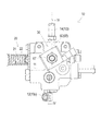
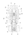
バルブ装置10について、図1乃至図6より説明する。バルブ装置10は、バルブケース11を有しており、バルブケース11内に調圧用リリーフ弁15、流量制御弁16、方向制御弁20、可変絞り弁25が内装されている。また、リフトシリンダ2への配管接続のためにバルブケース11に外付けされるマニフォールド40に電磁ストップバルブ30が装着されている。
The
スプール弁である方向制御弁20は、バルブケース11に形成されたポンプ通路20p、タンク通路20t、シリンダ通路20c、通路20rをそれぞれ開閉するランド部を備えている。バルブケース11内には、ポンプ通路20pより延出されるようにポンプ油路11aが形成されており、バルブケース11の外側面におけるポンプ油路11aの開口端部をバルブケース11のポンプポート11pとしている。このポンプポート11pとしてのポンプ油路11aの開口端部に、管継手12が装着されており、バルブケース11のポンプポート11p及び管継手12にて、図1に示すバルブ装置10のポンプポート10pが構成されている。管継手12には、図1に示す油路L1としての圧油管が接続される。また、管継手12内には、図1に示すラインフィルタ13が設けられており、油路L1としての圧油管からの油がラインフィルタ13にて濾過されてポンプ油路11a内に流入するものとしている。
The
バルブケース11内において、ポンプ油路11aには、調圧用リリーフ弁15及び流量制御弁16が接続されており、ポンプポート10pとしての管継手12よりポンプ油路11aに流入する油圧ポンプ11からの吐出油が、調圧用リリーフ弁15にて調圧された後、さらに、流量制御弁16にて調量され、方向制御弁20のポンプポート20pへと供給される。前記ポンプポート10pとしての管継手12、及び、タンクポート10tとしての管継手13を外側に備える、前記シリンダポート10cとしての管継手14が電磁ストップバルブ30に設けられなお、管継手12内に、図1にて図示されるラインフィルタ13、管継手17内に、図1にて図示されるラインフィルタ18が装着されている。
In the
また、バルブケース11内には、調圧用リリーフ弁15のリリーフ通路15a、及び流量制御弁16のリリーフ通路16aと合流するように、タンク通路20tより延出されるタンク油路11bが形成されており、バルブケース11の外側面(本実施例ではポンプポート11pの反対側)におけるタンク油路11bの開口端部をバルブケース11のタンクポート11tとしている。このタンクポート11tとしてのタンク油路11bの開口端部に、管継手14が嵌装されており、バルブケース11のタンクポート11t及び管継手14にて、図1に示すバルブ装置10のタンクポート10tが構成されている。管継手14には、図1に示す油路L2としての圧油管が接続される。また、バルブケース11内において、通路20rから可変絞り弁25を経た油をタンク油路11bへと油を送るための油路11rが形成されている。
A
さらにバルブケース11内には、シリンダ通路20cより延出されるシリンダ油路11cが形成されており、その開口端部をバルブケース11のシリンダポート11dとしている。さらに、バルブケース11内にて、シリンダ油路11cから流量制御弁16へと分岐するパイロット油路11eが形成されており、方向制御弁20を中立位置から上昇位置に至る過渡期において該制御弁20がシリンダポート10cへの流量を制限するときにその余剰油を排出するべく流量制御弁16が開閉するものとなっている。
Further, a
バルブケース11に、マニフォールド40を介して、電磁ストップバルブ30が外付け装着される。マニフォールド40は、その内部に電磁ストップバルブ30のチェック弁アセンブリ50を収容する弁室43を形成し、また、弁室43を介して互いに直角方向に接続されるポンプ・タンク側油路42及びシリンダ側油路44を形成している。ポンプ・タンク側油路42の開口端部がマニフォールド40のポンプ・タンクポート41とされる。このポンプ・タンクポート41としてのマニフォールド40の端部を、バルブケース11のシリンダポート11dとしての開口端部に嵌入することで、電磁ストップバルブ30がバルブケース11に装着され、また、バルブケース11内のシリンダ油路11cとマニフォールド40内のポンプ・タンク側油路42とが連通する。
An
一方、シリンダ側油路44の開口端部をマニフォールド40のシリンダポート45としており、このシリンダポート45としての開口端部に、管継手17が嵌装され、マニフォールド40のシリンダポート45及び管継手17により、図1に示すバルブ装置10のシリンダポート10cが構成されている。管継手17には、図1に示す油路L3としての圧油管が接続される。また、管継手17内には、図1に示すラインフィルタ18が設けられている。
On the other hand, the opening end of the cylinder
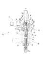
次に、図1及び図6等より、バルブ装置10における方向制御弁20について詳述する。方向制御弁20は、スプール21を備えており、スプール21は、その軸心方向の移動にて、上昇位置U、中立位置N、下降位置Dに切り換えられる。スプール21は、該スプール21に巻装されたバネ22にて、下降位置Dへと付勢されている。下降位置Dで、スプール21は、その外周に設けたランドにて、ポンプ通路20pとタンク通路20tとを連通して、ポンプポート10pからの吸入油をシリンダ通路20cへは流さずにタンクポート10tへと流通するとともに、シリンダ通路20cと通路20rとを連通し、 リフトシリンダ2の油室2aからシリンダ通路20cへと流入した油を、可変絞り弁25を介してタンクポート10tへと排出するものとしている。なお、絞り弁25は、シリンダ通路20cから排出油路11bへの流速を制限することで、自重で下降しようとするリフトアーム1の速度を抑制する機能を有するが、これに加え、中立位置Nから下降位置Dまでの移行途中の絞り下降位置Daにスプール21がある状態においては、スプール21内でのシリンダ通路20cから通路20rへの油の流れがさらに絞られて、作業機が急に下降開始することがないようにしている。
Next, the
下降位置Dから(絞り下降位置Daを経て)、バネ22に抗する方向(図6で矢印の向き)にスプール21を移動させることで、スプール21は、まず、中立位置Nに到達する。中立位置Nでは、ポンプ通路20pとタンク通路20tとが連通したままである一方、スプール21は、シリンダ通路20cを通路20rからもタンク通路20tからも遮断する。これにより、リフトシリンダ2の油室2aからシリンダ通路20cに油が流入しても、絞り通路20rへと流れることができないので、リフトシリンダ2からの油の排出を停止する。また、シリンダ通路20cはポンプ通路20pにも連通していないので、ポンプポート10pからの油がリフトシリンダ2へと供給されることもない。こうして、中立位置Nでは、シリンダ通路20cの油が、前述のようにリフトシリンダ2からの負荷によりタンクポート10t側へと漏れるという事態が生じない限り、流れることがないので、リフトシリンダ2の油室2a内の油圧はそのまま保持され、リフトアーム1はそのときの位置で保持される。
By moving the
さらにバネ22に抗する方向にスプール21を移動させて、上昇位置Uに到達させると、スプール21は、そのランドを介して、ポンプ通路20pをシリンダ通路20cに接続する一方、タンク通路20t及び通路20rをそれぞれ閉じて、ポンプポート10pからの吸入油をシリンダ油路20dへと供給し、さらには、ポンプポート10pからの油の油圧にて電磁ストップバルブ30のチェック弁32を開弁して、リフトシリンダ2の油室2aにポンプポート10pからの吸入油を供給し、リフトアーム1を上方回動するものである。なお、中立位置Nから上昇位置Uまでの移行途中の絞り上昇位置Uaにスプール21がある状態においては、ポンプ通路20pからシリンダ通路20cを通過する油の流れがランドの表面に形成した切り欠きで制限されて、作業機が急に上昇開始することがないようにしている。
When the
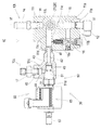
次に、電磁ストップバルブ30の構成について図1乃至図5、図7乃至図10より詳述する。電磁ストップバルブ30は、チェック弁アセンブリ50及びソレノイド60を組み合わせたカートリッジ式に構成される。チェック弁アセンブリ50は、弁シート部材51、可動弁部材52、スプール53、バネ54、ボールチェック弁55を組み合わせてなる。弁シート部材51はマニフォールド40の弁室43内に嵌装固定されており、そのナット部51dをマニフォールド40の外側に配している。弁シート部材51の、ポンプ・タンク側油路42に対峙する部分には、ポンプ・タンク側ポート51aが開口しており、シリンダ側油路44に対峙する部分には、シリンダ側ポート51cが開口している。また、弁シート部材51の、ポンプ・タンク側ポート51aとシリンダ側ポート51cとの間の部分に弁座51bが形成されている。
Next, the configuration of the
ポペット形状の可動弁部材52は、弁シート部材51内にてポンプ・タンク側油路42と同一軸心上(以下、電磁ストップバルブ30の軸心方向とする)に摺動自在に配設されている。可動弁部材52が弁シート部材51の弁座51bに着座することで、弁シート部材51のポンプ・タンク側ポート51aとシリンダ側ポート51cとの間を遮断し、ポンプ・タンク側油路42とシリンダ側油路44との間の油の流通を遮断する。この状態が、電磁ストップバルブ30の閉弁状態である。そして、可動弁部材52が、ポンプ・タンク側油路42に対し反対側に摺動して、弁座51bから離れることで、弁シート部材51内に、ポンプ・タンク側ポート51aとシリンダ側ポート51cとが連通する隙間ができ、ポンプ・タンク側油路42とシリンダ側油路44との間で油が流通可能となる。この状態が、電磁ストップバルブ30の開弁状態である。また、前述の弁シート部材51のナット部51d内には背圧室51eが形成されている。
The poppet-shaped
可動弁部材52内にはスプール室52aが形成されており、また、スプール室52aと、弁シート部材51のシリンダ側ポート51cとを常時(可動弁部材52が弁座51bに着座するか否かにかかわらず)連通する油路52bが形成されている。スプール53は、可動弁部材52のスプール室52a内にて、電磁ストップバルブ30の軸心方向に、可動弁部材52に対して相対摺動自在に配設されている。スプール53の外周部には螺旋溝53aが形成されており、油路52bを介してスプール室52a内に流入する油が、螺旋溝53aを介して、背圧室51eに流入可能となっている。
A
さらに可動弁部材52には、スプール室52aと、弁シート部材51のポンプ・タンク側ポート51aとを連通するように、オリフィス52cが形成されている。スプール室52aに臨むオリフィス52cの開口端は、通常は、スプール53の先端にて閉じられるものとなっている(図7、図8、図10参照)。また、スプール室52a内にて、可動弁部材52とスプール53との間にバネ54が介設されている。
Further, the
可動弁部材52の、ポンプ・タンク側ポート51aに臨む先端部分内にはボールチェック弁55が設けられている。ポンプ・タンク側ポート51aに臨むオリフィス52cの開口端は、ポンプ・タンク側ポート51aと背圧室51eが同圧なら、ボールチェック弁55に閉じられることなく、ポンプ・タンク側ポート51aに連通している(図7、図9、図10参照)が、背圧室51eよりポンプ・タンク側ポート51aの圧力が高くなると、その油圧にてボールチェック弁55が押圧され、ポンプ・タンク側ポート51aに臨むオリフィス52cの開口端を閉じる(図8参照)。
A
ソレノイド60は、鉄心筒61、可動鉄心62、固定鉄心63、バネ64、コイル65等を組み合わせてなる。鉄心筒61はソレノイド60全体の取付部材となっており、鉄心筒61をチェック弁アセンブリ50の弁シート部材51のナット部51dにて開口する背圧室51eに嵌入固定することで、ソレノイド60をチェック弁アセンブリ50に装着している。背圧室51eに嵌入固定された鉄心筒61内には、可動鉄心62が、電磁ストップバルブ30の軸心方向に摺動自在に設けられていて、その先端部を、可動弁部材52より背圧室51e内へと突出するスプール53の端部に固着し、スプール53と可動鉄心62とが一体で電磁ストップバルブ30の軸心方向に摺動するものとしている。
The
可動鉄心62の、チェック弁アセンブリ50とは反対側に、固定鉄心63が、可動鉄心62と同一軸心上に延設されており、固定鉄心63及び鉄心筒61にコイル65が周設されている。コイル65が通電されると、固定鉄心63が励磁され、可動鉄心62は、チェック弁アセンブリ50とは反対側、すなわち、電磁ストップバルブ30の開弁方向に摺動して固定鉄心63に吸着される。また、可動鉄心62の内部にバネ64が配設されており、該バネ64により、チェック弁アセンブリ50の側、すなわち、電磁ストップバルブ30の閉弁方向に、可動鉄心62を付勢している。なお、図5等に示すように、可動弁部材52が弁シート部材51の弁座51bに着座しているとき、すなわち、電磁ストップバルブ30が閉弁しているときは、可動鉄心62と固定鉄心63との間に隙間Gが空く。
On the opposite side of the
なお、可動鉄心62及び固定鉄心63の軸心部を貫通するように、強制開弁用ロッド66が設けられており、その外端部は固定鉄心63の外側に突出し、該突出端部に強制開弁用ツマミ67が固設されている。例えば、エンジン停止後や電気系統の故障でソレノイド60への通電ができないときに作業機を下降させたい場合に、強制開弁用ツマミ67を手動操作して強制開弁用ロッド66を引くことで、強制開弁用ロッド66が可動鉄心62を固定鉄心63に押しつける状態となり、可動弁部材52が弁座51bより離れ、電磁ストップバルブ30を強制的に開弁させることができる構成となっている。
Note that a forced
ソレノイド60の励磁・非励磁の制御、及び、方向制御弁20のシフトと関連しての、電磁ストップバルブ30のチェック弁アセンブリ50の状態の変化やマニフォールド40内における油の流れの変化等について、図7乃至図10を用いて説明する。
Regarding the change in the state of the
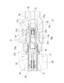
まず、図7は、ソレノイド60が非励磁の状態で、閉弁状態にある電磁ストップバルブ30、図8は、ソレノイド60が非励磁の状態で、開弁状態にある電磁ストップバルブ30の様子を示している。コイル65が通電されないときは、可動鉄心62と一体に移動するスプール53の先端がバネ54により、前述の如くオリフィス52cの開口端を閉じる状態にて可動弁部材52に押接されており、これにより、可動弁部材52が弁シート部材51の弁座51bに押圧される。
First, FIG. 7 shows the state of the
この状態において、方向制御弁20が中立位置Nまたは下降位置Dのときでは、シリンダ側ポート51cに比べてポンプ・タンク側ポート51a内の油圧が低く、図7に示すように、電磁ストップバルブ30が閉弁する。
In this state, when the
方向制御弁20が下降位置Dにあるときのみならず、中立位置Nにあるときも、リフトアーム1に連結される作業機の自重により、リフトシリンダ2には、ピストンロッド3を収縮する方向の負荷がかかる。しかし、ソレノイド60が非励磁状態で、図7に示すように、電磁ストップバルブ30が閉弁している限りは、このようにシリンダ側油路44の油は、オリフィス51bからスプール室52a内に流入して背圧室51e内へと導かれ、この油圧力にバネ54の付勢力が加わることで、可動弁部材52に対しては、閉弁方向に作用する。したがって、方向制御弁20を中立位置Nにセットしているにもかかわらず作業機が不測に下降してしまうというような事態を生じることはない。いいかえれば、電磁ソレノイドバルブ30が、リフトシリンダ2から方向制御弁20への油漏れを防止するストップバルブ(安全弁)として機能しているのである。
Not only when the
また、ソレノイド60が非励磁の状態で方向制御弁20を上昇位置Uにすれば可動弁部材52はその油圧力を受けて開弁し、リフトシリンダ2の油室2aに給油され作業機を上昇させることができる。したがって、ソレノイド60が非励磁のときの電磁ソレノイドバルブ30は、マニフォールド40のポンプ・タンク側油路42からシリンダ側油路44への油の流れのみを許容するチェック弁としても機能するものといえる。
If the
次に、図9及び図10は、ソレノイド60を励磁させたときの電磁ストップバルブ30の様子を示している。ソレノイド60を励磁すると、可動鉄心62が固定鉄心63へと摺動し、固定鉄心63に吸着され、スプール53も、ソレノイド60側に可動鉄心62と一体に摺動する。図9は、可動鉄心62が固定鉄心63に吸着された当初の状態を示すものであり、スプール53は、バネ54の付勢力に抗して、可動鉄心62とともに瞬間的に摺動するが、可動弁部材52は、スプール室52a内の油圧にて、なおも、弁座51bに着座したままの状態である。
Next, FIGS. 9 and 10 show the state of the
スプール53の先端が、スプール弁室52aに臨むオリフィス52cの開口端より離れると、スプール室52a及び油路52bやオリフィス52cを介して、ポンプ・タンク側ポート51aとシリンダ側ポート51cとが連通する。したがって、方向制御弁20を下降位置Dにしたときにソレノイド60を励磁させればリフトシリンダ2の油室2aから油が抜けて作業機を下降させることができる。
When the tip of the
ソレノイド60を非励磁状態から励磁状態に切り換えるのは、例えば電磁ストップバルブ30を開くためのスイッチを車両の運転席近傍に設けておき、オペレータが手動でスイッチの切換操作をするということが考えられる。しかし、ストップバルブの操作ミス(操作忘れ)を防ぐという観点からは、ソレノイド60の励磁・非励磁の切換を自動制御とすることが好ましく、また、車両の運転席近傍にある作業機昇降用の操作具(レバーやスイッチ等)を手動操作しての方向制御弁20のシフトにこのソレノイド60の励磁・非励磁の切換を電気的に連係させることが好ましい。したがって、当該車両には、コントローラを設け、作業機昇降用の操作具の操作位置、あるいは方向制御弁20のスプール21の操作位置の検出に基づき、コントローラより電磁ストップバルブ30のソレノイド60に指令信号を送るように構成した、電磁ストップバルブ30の自動制御システムを設けていることが好ましい。
The reason for switching the
このような自動制御システムを構成するとなると、方向制御弁20を、下降位置D、中立位置N、上昇位置Uの各位置に設定したときに、ソレノイド60を励磁とすべきか非励磁とすべきかが重要となる。まず、ソレノイド60を励磁しなければ電磁ストップバルブ30がシリンダ側ポート51cからポンプ・タンク側ポート51aへと油を流すように開弁することはないので、方向制御弁20を下降位置Dに設定したときは、ソレノイド60を励磁するものとすべきである。方向制御弁20を上昇位置Uに設定したときは、ソレノイド60を励磁していても非励磁としていても、電磁ストップバルブ30はポンプ・タンク側ポート51aからシリンダ側ポート51cへと油を流すように開弁することができるので、どちらでもよいが、コストパフォーマンスの面からいえば、非励磁とすることが好ましいものと考えられる。
When such an automatic control system is configured, when the
そして、方向制御弁20を中立位置Nとしたときは、ソレノイド60を非励磁とすれば、非励磁位置30aにある電磁ストップバルブ30は、確実にシリンダ側ポート51cからポンプ・タンク側ポート51aへの油の流れを遮断するので、作業機の不測の下降を防止することができる。したがって、方向制御弁20を中立位置Nにしたときに電磁ストップバルブ30が作業機の不測の下降を防止するためのストップバルブとして機能する。
When the
以上の如く、本発明の電磁ストップバルブ30付きのバルブ装置10を用いれば、方向制御弁20を下降位置Dとしたときのみ、電磁ストップバルブ30のソレノイド60を励磁する構造とすればよいので、電力消費を抑えつつも確実に、方向制御弁20を中立位置Nとしたときの作業機の自然降下を抑制することができるものである。
As described above, if the
なお、電磁ストップバルブ30に代えて、従来の、手動操作によるスイッチの切換操作等にて切り換えられる構成のストップバルブをバルブ装置10に装着するものとしてもよい。この場合には、バルブケース11のシリンダポート11dにストップバルブのポンプ・タンク側ポートとしての開口端部を接続すればよい。逆にいえば、本発明の電磁ストップバルブ30付きバルブ装置10は、電磁ストップバルブ30を従来のストップバルブに容易に置き換えることができるように、従来、作業機の昇降制御装置として用いられていた調圧用リリーフ弁15、流量制御弁16、方向制御弁20、可変絞り弁25等を内装するバルブケース11をそのまま用いることによってモジュール化を図っているのである。
Instead of the
1 リフトアーム
2 リフトシリンダ
10 バルブ装置
11 バルブケース
11p (バルブケース11の)ポンプポート
11t (バルブケース11の)タンクポート
11d (バルブケース11の)シリンダポート
20 方向制御弁
30 電磁ストップバルブ
40 マニフォールド
42 ポンプ・タンク側油路
44 シリンダ側油路
50 チェック弁アセンブリ
60 ソレノイド
DESCRIPTION OF SYMBOLS 1
Claims (3)
該マニフォールドは、内部にポンプ・タンク側油路とシリンダ側油路とを形成し、該ポンプ・タンク側油路の端部が開口する部分を該バルブケースの該シリンダポートに接続して該バルブケースに着脱自在に装着するものであり、該マニフォールドにおける該シリンダ側油路の開口端部を該油圧リフトシリンダに接続可能としていることを特徴とする作業機の昇降制御装置。 A hydraulic lift cylinder for raising and lowering the work implement, which is configured to supply pressure oil when raising the work implement and discharging pressure oil when lowering the work implement; A directional control valve for controlling supply / discharge, a valve case including the directional control valve, including a pump port, a tank port, and a cylinder port, and the cylinder port and the hydraulic pressure of the valve case A lifting control device for a work machine comprising a manifold interposed between a lift cylinder and an electromagnetic stop valve mounted on the manifold,
The manifold forms a pump / tank side oil passage and a cylinder side oil passage inside, and connects a portion where an end of the pump / tank side oil passage opens to the cylinder port of the valve case. A lifting control device for a working machine, which is detachably attached to a case, wherein an opening end of the cylinder side oil passage in the manifold can be connected to the hydraulic lift cylinder.
The directional control valve has a raised position for supplying pressure oil to the hydraulic lift cylinder, a lowered position for discharging pressure oil from the hydraulic lift cylinder, and supply / discharge of pressure oil in the hydraulic lift cylinder. The solenoid can be set to any neutral position for stopping, and the solenoid of the electromagnetic stop valve is energized only when the directional control valve is set to the lowered position. The lifting control device for a working machine according to claim 2, wherein the lifting control device is linked to an operation tool.
Priority Applications (2)
| Application Number | Priority Date | Filing Date | Title |
|---|---|---|---|
| JP2015257021A JP6651101B2 (en) | 2015-12-28 | 2015-12-28 | Work machine lifting control |
| CN201611220310.XA CN107013513B (en) | 2015-12-28 | 2016-12-26 | Lifting control device for working machine |
Applications Claiming Priority (1)
| Application Number | Priority Date | Filing Date | Title |
|---|---|---|---|
| JP2015257021A JP6651101B2 (en) | 2015-12-28 | 2015-12-28 | Work machine lifting control |
Publications (2)
| Publication Number | Publication Date |
|---|---|
| JP2017120109A true JP2017120109A (en) | 2017-07-06 |
| JP6651101B2 JP6651101B2 (en) | 2020-02-19 |
Family
ID=59271875
Family Applications (1)
| Application Number | Title | Priority Date | Filing Date |
|---|---|---|---|
| JP2015257021A Active JP6651101B2 (en) | 2015-12-28 | 2015-12-28 | Work machine lifting control |
Country Status (2)
| Country | Link |
|---|---|
| JP (1) | JP6651101B2 (en) |
| CN (1) | CN107013513B (en) |
Citations (6)
| Publication number | Priority date | Publication date | Assignee | Title |
|---|---|---|---|---|
| JPS5610309U (en) * | 1979-07-04 | 1981-01-29 | ||
| JPS58110204U (en) * | 1982-01-23 | 1983-07-27 | 三菱農機株式会社 | Mobile agricultural machinery lifting device |
| JPH0653802U (en) * | 1992-12-28 | 1994-07-22 | 株式会社島津製作所 | Cylinder drive circuit |
| JP2004036750A (en) * | 2002-07-03 | 2004-02-05 | Aichi Corp | Cylinder operation control device |
| US20050044849A1 (en) * | 2003-08-09 | 2005-03-03 | Deere & Company, A Delaware Corporation | Hydraulic control arrangement for a mobile work machine |
| JP2009156366A (en) * | 2007-12-27 | 2009-07-16 | Hitachi Constr Mach Co Ltd | Drive device for high lift working machine |
Family Cites Families (4)
| Publication number | Priority date | Publication date | Assignee | Title |
|---|---|---|---|---|
| JPH07332309A (en) * | 1994-06-13 | 1995-12-22 | Ichikawagumi Kk | Hydraulic device |
| DE19604315A1 (en) * | 1996-02-07 | 1997-08-14 | Bosch Gmbh Robert | Electromagnetically operated valve, in particular for hydraulic brake systems in motor vehicles |
| JP5356159B2 (en) * | 2009-09-02 | 2013-12-04 | 日立建機株式会社 | Hydraulic drive device for hydraulic working machine |
| EP2918854B1 (en) * | 2012-11-07 | 2018-06-27 | Hitachi Construction Machinery Co., Ltd. | Hydraulic drive device for construction machinery |
-
2015
- 2015-12-28 JP JP2015257021A patent/JP6651101B2/en active Active
-
2016
- 2016-12-26 CN CN201611220310.XA patent/CN107013513B/en active Active
Patent Citations (6)
| Publication number | Priority date | Publication date | Assignee | Title |
|---|---|---|---|---|
| JPS5610309U (en) * | 1979-07-04 | 1981-01-29 | ||
| JPS58110204U (en) * | 1982-01-23 | 1983-07-27 | 三菱農機株式会社 | Mobile agricultural machinery lifting device |
| JPH0653802U (en) * | 1992-12-28 | 1994-07-22 | 株式会社島津製作所 | Cylinder drive circuit |
| JP2004036750A (en) * | 2002-07-03 | 2004-02-05 | Aichi Corp | Cylinder operation control device |
| US20050044849A1 (en) * | 2003-08-09 | 2005-03-03 | Deere & Company, A Delaware Corporation | Hydraulic control arrangement for a mobile work machine |
| JP2009156366A (en) * | 2007-12-27 | 2009-07-16 | Hitachi Constr Mach Co Ltd | Drive device for high lift working machine |
Also Published As
| Publication number | Publication date |
|---|---|
| CN107013513A (en) | 2017-08-04 |
| JP6651101B2 (en) | 2020-02-19 |
| CN107013513B (en) | 2021-05-14 |
Similar Documents
| Publication | Publication Date | Title |
|---|---|---|
| KR101859631B1 (en) | Pressure compensated hydraulic system having differential pressure control | |
| US9797117B2 (en) | Fluid pressure control device | |
| US8925439B2 (en) | Valve control valve circuit for operating a single acting hydraulic cylinder | |
| EP1764339B1 (en) | Hydraulic arrangement for a lifting arm pivotably mounted on a vehicle | |
| JP2012527586A (en) | Hydraulic switching mechanism for mobile hydraulic device, mobile hydraulic machine and valve unit | |
| JP2007239992A (en) | Hydraulic system including plurality of pressure relief level | |
| US10132059B2 (en) | Fluid pressure control device | |
| JP2017120109A (en) | Lift control device for work machine | |
| JP6621382B2 (en) | Hydraulic drive device for work equipment | |
| JP2008061551A (en) | Elevator for implement of ground working vehicle | |
| JP2020063788A (en) | Descent preventive valve device, blade device and work machine | |
| KR102078496B1 (en) | Pump gear | |
| JP3274305B2 (en) | Operation structure for work equipment of work vehicle | |
| JP2018031439A (en) | Hydraulic drive unit of working machine | |
| JP3078995B2 (en) | Operation structure for work equipment of work vehicle | |
| JP3077258B2 (en) | Hydraulic equipment for lifting and lowering tractor working equipment | |
| JP2007155109A (en) | Industrial machine control device | |
| EP2196682A1 (en) | A hydraulic device for controlling an actuator in a work vehicle | |
| WO2018098138A1 (en) | Hydraulic valve with switching regeneration circuit | |
| JP4484610B2 (en) | Work vehicle | |
| JP2002061606A (en) | Regenerating oil quantity control valve of hydraulic cylinder | |
| JP4233203B2 (en) | Hydraulic control device | |
| JPH0114086Y2 (en) | ||
| CN114207296A (en) | Hydraulic system architecture and two-way proportional valve usable in the system architecture | |
| JPH08188095A (en) | Oil hydraulic circuit of working vehicle |
Legal Events
| Date | Code | Title | Description |
|---|---|---|---|
| A621 | Written request for application examination |
Free format text: JAPANESE INTERMEDIATE CODE: A621 Effective date: 20180903 |
|
| A977 | Report on retrieval |
Free format text: JAPANESE INTERMEDIATE CODE: A971007 Effective date: 20190612 |
|
| A131 | Notification of reasons for refusal |
Free format text: JAPANESE INTERMEDIATE CODE: A131 Effective date: 20190625 |
|
| TRDD | Decision of grant or rejection written | ||
| A01 | Written decision to grant a patent or to grant a registration (utility model) |
Free format text: JAPANESE INTERMEDIATE CODE: A01 Effective date: 20191126 |
|
| A61 | First payment of annual fees (during grant procedure) |
Free format text: JAPANESE INTERMEDIATE CODE: A61 Effective date: 20191218 |
|
| R150 | Certificate of patent or registration of utility model |
Ref document number: 6651101 Country of ref document: JP Free format text: JAPANESE INTERMEDIATE CODE: R150 |
|
| R250 | Receipt of annual fees |
Free format text: JAPANESE INTERMEDIATE CODE: R250 |
|
| R250 | Receipt of annual fees |
Free format text: JAPANESE INTERMEDIATE CODE: R250 |