JP2017119528A - Connection member for container - Google Patents
Connection member for container Download PDFInfo
- Publication number
- JP2017119528A JP2017119528A JP2015256953A JP2015256953A JP2017119528A JP 2017119528 A JP2017119528 A JP 2017119528A JP 2015256953 A JP2015256953 A JP 2015256953A JP 2015256953 A JP2015256953 A JP 2015256953A JP 2017119528 A JP2017119528 A JP 2017119528A
- Authority
- JP
- Japan
- Prior art keywords
- container
- shape
- connecting member
- containers
- connection member
- Prior art date
- Legal status (The legal status is an assumption and is not a legal conclusion. Google has not performed a legal analysis and makes no representation as to the accuracy of the status listed.)
- Granted
Links
Images


Abstract
Description
本発明は、容器用連結部材に関する。 The present invention relates to a connecting member for containers.
例えば、スポーツ観戦施設、ファストフード店等では、飲料が紙製、プラスチック製等の容器で提供されることが多い。飲料用の容器としては、冷たい飲料がすぐに温くなったり、温かい飲料がすぐに冷めたりすることを抑制する目的で、二重構造によって断熱性能を向上させた二重構造容器が提案されている。 For example, in sports watching facilities, fast food restaurants, etc., beverages are often provided in paper or plastic containers. As a container for beverages, a double-structure container with improved heat insulation performance by a double structure has been proposed for the purpose of suppressing cold drinks from immediately warming up and hot drinks from cooling down immediately. .
具体的には、例えば、下記の容器(i)〜(iii)が挙げられる。
(i)上端に開口が形成され、かつ上端部が外向きにカールされた胴部を備える容器本体と、容器本体の外側に装着される外装スリーブとを備え、外装スリーブを装着した状態で、胴部の外面と外装スリーブの内面の間に空隙が形成される二重構造容器(特許文献1)。
(ii)上端に開口が形成された胴部を備える容器本体と、筒部の上端から内側に折り返すように複数の耳部が延設された、容器本体の外側に取り付けられる外筒とを備え、外筒を取り付けた状態で、胴部と筒部の間に空隙が形成される二重構造容器(特許文献2)。
(iii)上端部に内向きに突出した第1の縁円部が設けられた第1の容器と、第1の容器の内径よりも外径が小さく、上端部に外向きに突出した第2の縁円部が設けられた第2の容器と、を備え、第1の容器内に第2の容器を挿入したときに、第1の縁円部と第2の縁円部が当接し、第1の容器と第2の容器の間に空隙が形成される二重構造容器(特許文献3)。
Specific examples include the following containers (i) to (iii).
(I) a container main body having a body with an opening formed at the upper end and the upper end curled outward; and an outer sleeve mounted on the outside of the container main body, with the outer sleeve mounted, A double structure container in which a gap is formed between the outer surface of the trunk and the inner surface of the outer sleeve (Patent Document 1).
(Ii) a container main body including a barrel portion having an opening formed at the upper end, and an outer cylinder attached to the outside of the container main body with a plurality of ears extending from the upper end of the cylindrical portion to the inside. A double structure container in which a gap is formed between the body portion and the cylinder portion with the outer cylinder attached (Patent Document 2).
(Iii) a first container provided with a first edge circle projecting inwardly at the upper end, and a second container having an outer diameter smaller than the inner diameter of the first container and projecting outward at the upper end A second container provided with an edge circle, and when the second container is inserted into the first container, the first edge circle and the second edge circle abut, A double-structured container in which a gap is formed between the first container and the second container (Patent Document 3).
しかし、容器(i)〜(ii)において十分な断熱性能を得るには、容器本体の胴部の大部分を覆うサイズの外装スリーブ又は外筒を別途製造する必要があるため、コスト面で不利である。容器(iii)においても同様に、十分な断熱性能を得るには、第1の容器の大部分を覆うサイズの第2の容器を別途製造する必要がある。また、容器(iii)における口をつける部分は、第1の縁円部と第2の縁円部とが重なっているために厚みがあり、口当たりが悪くなる問題もある。 However, in order to obtain sufficient heat insulation performance in the containers (i) to (ii), it is necessary to separately manufacture an outer sleeve or an outer cylinder having a size that covers most of the trunk portion of the container body, which is disadvantageous in terms of cost. It is. Similarly, in the case of the container (iii), in order to obtain sufficient heat insulation performance, it is necessary to separately manufacture a second container having a size that covers most of the first container. Moreover, since the 1st edge circle | round | yen part and the 2nd edge circle | round | yen part have overlapped, the part which attaches the mouth in a container (iii) has thickness, and there also exists a problem which mouthfeel becomes bad.
本発明は、容器を2つ用いて、低コストで、口当たりが悪くなることを抑制しつつ、優れた断熱性能を有する二重構造容器を形成できる容器用連結部材を提供することを目的とする。 An object of the present invention is to provide a container connecting member that can form a double-structure container having excellent heat insulation performance while using two containers and suppressing deterioration of mouthfeel at low cost. .
本発明は、以下の構成を有する。
[1]底面部と、該底面部の周縁から立ち上がり、かつ上端に向かうにつれて拡径した胴部とを備え、該胴部の上端に開口が形成された第1の容器と第2の容器とを連結して二重構造容器とする容器用連結部材であって、前記第1の容器を前記胴部の外側面側から支持する支持部と、前記支持部と接続され、前記第2の容器により保持される保持部と、を備え、前記第1の容器が第2の容器内に挿入された状態で、前記支持部が前記第1の容器を支持し、前記保持部が前記第2の容器により保持されて、前記第1の容器の底面部が前記第2の容器の底面部から離間し、前記第1の容器と前記第2の容器の間に空隙が形成される、容器用連結部材。
[2]前記保持部が前記支持部よりも下側に設けられ、かつ前記保持部に前記第2の容器の胴部の上端から外側に張り出すように形成されるフランジ部が嵌まり込む溝状の嵌合部が形成されている、[1]に記載の容器用連結部材。
[3]帯状の前記支持部及び前記保持部を備え、全体として帯状である[1]又は[2]に記載の容器用連結部材。
[4]形状及び大きさが同じ第1の容器と第2の容器とを連結して二重構造容器とするための容器用連結部材である、[1]〜[3]のいずれかに記載の容器用連結部材。
The present invention has the following configuration.
[1] A first container and a second container each including a bottom surface portion and a body portion that rises from the periphery of the bottom surface portion and expands toward the upper end, and has an opening formed at the upper end of the body portion. A connecting member for a container having a double-structured container, wherein the second container is connected to the supporting part for supporting the first container from the outer surface side of the body part, and is connected to the supporting part. A holding portion held by the first container, wherein the support portion supports the first container in a state where the first container is inserted into the second container, and the holding portion is the second container. A container connection, held by a container, wherein a bottom surface portion of the first container is separated from a bottom surface portion of the second container, and a gap is formed between the first container and the second container. Element.
[2] A groove in which the holding portion is provided below the support portion, and a flange portion is formed in the holding portion so as to protrude outward from the upper end of the body portion of the second container. The container connecting member according to [1], wherein a fitting portion having a shape is formed.
[3] The container connecting member according to [1] or [2], including the belt-shaped support portion and the holding portion, and having a belt shape as a whole.
[4] The connection member for containers according to any one of [1] to [3], which is a container connection member for connecting a first container and a second container having the same shape and size to form a double structure container. Connecting member for container.
本発明の容器用連結部材によれば、容器を2つ用いて、低コストで、口当たりが悪くなることを抑制しつつ、優れた断熱性能を有する二重構造容器を形成することができる。 According to the container connecting member of the present invention, it is possible to form a double structure container having excellent heat insulation performance while using two containers and suppressing the deterioration of mouthfeel at low cost.
本発明の容器用連結部材は、底面部と、該底面部の周縁から立ち上がり、かつ上端に向かうにつれて拡径した胴部とを備え、該胴部の上端に開口が形成された第1の容器と第2の容器とを連結して二重構造容器とするための部材である。本発明の容器用連結部材は、形状及び大きさが同じ第1の容器と第2の容器とを連結して二重構造容器とするための部材であることが好ましい。なお、本発明の容器用連結部材は、形状や大きさが異なる第1の容器と第2の容器とを連結して二重構造容器とするための部材であってもよい。 The container connecting member of the present invention includes a bottom surface portion and a body portion that rises from the periphery of the bottom surface portion and has a diameter that increases toward the upper end, and an opening is formed at the upper end of the body portion. And a second container for connecting the container and the second container. The container connecting member of the present invention is preferably a member for connecting a first container and a second container having the same shape and size to form a double structure container. The container connecting member of the present invention may be a member for connecting a first container and a second container having different shapes and sizes to form a double structure container.
本発明の容器用連結部材は、第1の容器を胴部の外側面側から支持する支持部と、支持部と接続され、第2の容器により保持される保持部と、を備えている。本発明の容器用連結部材を用いた二重構造容器においては、第1の容器が第2の容器内に挿入された状態で、支持部が第1の容器を支持し、保持部が第2の容器により保持されることで、第1の容器の底面部が第2の容器の底面部から離間し、第1の容器と前記第2の容器の間に空隙が形成される。 The container connecting member of the present invention includes a support part that supports the first container from the outer surface side of the body part, and a holding part that is connected to the support part and is held by the second container. In the double-structured container using the container connecting member of the present invention, the support part supports the first container and the holding part is the second in a state where the first container is inserted into the second container. By being held by the container, the bottom surface portion of the first container is separated from the bottom surface portion of the second container, and a gap is formed between the first container and the second container.
[第1実施形態]
以下、本発明の容器用連結部材の一例を示してさらに説明する。
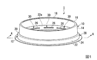
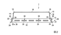
本実施形態の容器用連結部材1は、図1及び図2に示すように、支持体10と、保持体12とを備えている。支持体10と保持体12とは一体的に形成されている。容器用連結部材1は、全体として円環を形成する帯状部材である。
[First Embodiment]
Hereinafter, an example of the connecting member for containers of the present invention will be described and further described.
As shown in FIGS. 1 and 2, the
支持体10は、円筒状の第1筒部14と、第1筒部14の上端から全周にわたって内側に突出した円環状の支持部16とを備えている。このように、支持部16は、円環を形成する帯状になっている。
The
支持部16の内側には、平面視形状が円形の開口18が形成されている。開口18には、第1の容器が上方から挿入されて嵌まり込むようになっている。そして、その状態においては、支持部16の先端が第1の容器の胴部の外側面に当接して、該胴部を外側面側から支持するようになっている。支持部は、このように長尺の部材で、第1の容器の胴部の外側面に対して周方向に沿って囲うように接して第1の容器を支持するものが好ましい。
An opening 18 having a circular shape in plan view is formed inside the
第1筒部14は、この例では上端に向かうにつれて縮径している。なお、第1筒部14は、このような形態には限定されず、例えば、高さ方向において径が同じになっている形態であってもよい。また、第1筒部は、円筒状には限定されず、例えば、四角筒状、五角筒状、多角筒状等であってもよい。
In this example, the first
第1筒部14の高さは、特に限定されず、適用する第1の容器及び第2の容器の形状及び大きさに応じて適宜設定すればよい。
The height of the
支持部16の第1筒部14からの突出長さは、特に限定されず、適用する第1の容器及び第2の容器の形状及び大きさに応じて適宜設定すればよい。
The protruding length of the
開口18の平面視形状は、この例では円形状である。なお、開口18の平面視形状及び大きさは、特に限定されず、適用する第1の容器の形状及び大きさに合わせて、第1の容器の胴部を外側面側から安定して支持できるように設定すればよい。開口18の平面視形状としては、第1の容器を支持する部分において、第1の容器の胴部を高さ方向に垂直な方向に切断した断面形状と同じ形状であることが好ましい。
The planar view shape of the
保持体12は、第1張出部20、第2筒部22、第2張出部24、及び複数の係止部26を備えている。第1張出部20は、支持体10における第1筒部14の下端から、径方向の外側に円環状に張り出すように形成されている。第2筒部22は、第1張出部20の先端から下方に垂下され、円筒状に形成されている。第2張出部24は、第2筒部22の下端から、径方向の外側に円環状に張り出すように形成されている。複数の係止部26は、第2筒部22の内面22aにおいて周方向に一定の間隔を空けて、内面22aから突出するように断続的に形成されている。なお、係止部26は、第2筒部22の内面22aにおいて、周方向に全周にわたって連続的に環状に形成されていてもよい。
The
保持体12においては、第1張出部20、第2筒部22及び係止部26により保持部28が形成されている。保持部28は、円環状の第1張出部20と、円筒状の第2筒部22を備えていることから、円環を形成する帯状になっている。支持体10と保持体12とは一体的に形成されていることから、支持部16と保持部28とは互いに接続された状態になっている。本発明では、このように、支持部が帯状の場合、第2の容器によってより安定して保持されやすいため、保持部も帯状とし、容器用連結部材全体として帯状になるようにすることが好ましい。
In the holding
この例の保持部28の内側には、第1張出部20、第2筒部22及び係止部26により、溝状の嵌合部30が断続的に形成されている。第2の容器の上端の縁部に形成されたフランジ部が、保持部28における溝状の嵌合部30に嵌まり込むことで、保持部28が第2の容器によってしっかりと保持される。第1の容器が第2の容器内に挿入された状態で、支持部16によって第1の容器が支持され、保持部28が第2の容器に保持されることで、第1の容器の底面部が第2の容器の底面部から離間し、第1の容器と第2の容器の間に空隙が形成される。
Inside the holding
第1張出部20における第1筒部14側の基端から先端までの長さは、特に限定されず、第2の容器の形状及び大きさに合わせて適宜設定できる。第1張出部20の形状も、円環状には限定されず、第2の容器の形状に応じて適宜設定できる。
The length from the proximal end to the distal end of the first overhanging
第2筒部22の形状は、この例では円筒状であるが、円筒状には限定されず、第2の容器の開口部の形状に応じて適宜設定でき、例えば、四角筒状、五角筒状、多角筒状等であってもよい。第2筒部22は、この例では高さ方向において径が変化しない円筒状であるが、下端に向かうにつれて徐々に拡径又は縮径していてもよい。
第2筒部22の高さは、第1の容器及び第2の容器の形状に応じて適宜設定できる。
The shape of the second
The height of the
第2張出部24における第2筒部22側の基端から先端までの長さは、特に限定されない。
The length from the proximal end to the distal end of the second projecting
係止部26は、溝状の嵌合部30に第2の容器のフランジ部が嵌まり込んだ際に、該フランジ部の下面に引っ掛かって該フランジ部を係止する部分である。この例の係止部26は、第2筒部22の内側からの正面視形状が第2筒部22における周方向に長い長方形で、縦方向に切断した断面形状が先端に向うにつれて窄む台形状になっている。なお、係止部26の形状は、容器用連結部材1を第2の容器のフランジ部に装着する際に該フランジ部が係止部26を下方から上方に乗り越えることができ、かつ嵌まり込んだフランジ部を安定して係止できる範囲であれば、上記の形状には限定されない。
When the flange part of the second container is fitted into the groove-like
係止部26の第2筒部22の内面22aからの高さは、特に限定されず、容器用連結部材1を第2の容器のフランジ部に装着する際に該フランジ部が係止部26を下方から上方に乗り越えることができ、かつ嵌まり込んだフランジ部を安定して係止できる範囲で、適宜設定すればよい。
The height of the locking
保持体12の下端の内側には、平面視形状が円形の開口32が形成されている。開口32には、下方から第2の容器を挿入できるようになっている。開口32の平面視形状は、この例では円形状である。なお、開口32の平面視形状及び大きさは、特に限定されず、適用する第1の容器及び第2の容器、特に第2の容器の開口部の形状及び大きさに合わせて設定すればよい。
An
容器用連結部材1の材質は、特に限定されず、例えば、ポリスチレン等のポリスチレン系樹脂、ポリプロピレン等のポリオレフィン系樹脂、ポリエチレンテレフタレート等のポリエステル樹脂、塩化ビニル系樹脂、シリコーンゴム等が挙げられる。
The material of the connecting
容器用連結部材1は、公知の成形方法を利用して製造できる。成形方法としては、例えば、プレス成形、真空成形法、圧空成形法、圧空真空成形法、射出成形法、ブロー成形法等が挙げられる。具体例として、例えば、シートに対し、真空成形法、圧空成形法等により複数の容器用連結部材1を成形し、成形したシートを打ち抜きして抜き出す方法、上記のように成形したシートを裁断し、裁断したシートから容器用連結部材1を切り出す方法や、シリコーンゴムをプレス成形する方法等が挙げられる。
The connecting
(二重構造容器)
以下、図3に基づいて、形状及び大きさが同じ第1の容器100と第2の容器200を、本実施形態の容器用連結部材1を用いて二重構造容器とする態様について説明する。
(Double structure container)
Hereinafter, based on FIG. 3, the aspect which makes the
第1の容器100は、いわゆるコップであり、平面視円形状の底面部110と、底面部110の周縁から立ち上がる円筒状の胴部130と、胴部130の上端から全周にわたって径方向の外側に突出して形成された円環状のフランジ部150とを備え、胴部130の上端に開口130aが形成されている。第2の容器200は、第1の容器100と形状及び大きさが同じ容器であり、平面視円形状の底面部210と、底面部210の周縁から立ち上がる円筒状の胴部230と、胴部230の上端から全周にわたって径方向の外側に突出して形成された円環状のフランジ部250とを備え、胴部230の上端に開口230aが形成されている。
The
第1の容器100の胴部130と第2の容器200の胴部230は、上端から下端に向かって徐々に縮径した形状(テーパー形状)になっている。また、胴部130,230における底面部110,210寄りの部分には、より下方の部分の径が小さくなるように段差が形成され、その段差部分から底面部110,210にかけては徐々に拡径するようになっている。
フランジ部150,250は、胴部130,230の上端から略水平に延出し、先端を下側に巻き込んだカール状に形成されている。第1の容器100では、底面部110と胴部130とフランジ部150とは一体的に形成されている。同様に、第2の容器200では、底面部210と胴部230とフランジ部250とは一体的に形成されている。
The
The
第1の容器100及び第2の容器200のそれぞれの容量は、特に限定されず、例えば100〜800mL程度のものが挙げられる。
Each capacity | capacitance of the
なお、第1の容器100と第2の容器200はあくまでも一例であり、第1の容器の形状は、胴部が上端から下端に向かって縮径したテーパー形状で、第1の容器と第2の容器とがスタックできるようになっていればよく、本実施形態の形状には限定されない。
The
第1の容器100及び第2の容器200のそれぞれの材質は、特に限定されず、例えば、樹脂、紙等が挙げられる。樹脂としては、例えば、ポリエチレンテレフタレート等のポリエステル樹脂、ポリスチレン、ポリプロピレン、塩化ビニル系樹脂等が挙げられる。
さらに、第2の容器200の材質は、陶器、ガラス、金属などであってもよい。
第1の容器100及び第2の容器200は、透明であってもよく、不透明であってもよい。第1の容器100及び第2の容器200が透明であれば、第1の容器100及び第2の容器200を二重構造とした状態で、第1の容器100内に収容した飲料を視認できる。
The material of each of the
Furthermore, the material of the
The
容器用連結部材1を用いた二重構造容器300においては、容器用連結部材1が、保持部28が下側にされた状態で、第2の容器200のフランジ部250に上方から被せられており、フランジ部250が保持部28における嵌合部30に嵌め込まれている。これにより、保持部28が第2の容器200によって保持されている。さらに、容器用連結部材1における支持体10の上端の開口18には、第1の容器100が上方から挿入されており、その挿入された第1の容器100が支持部16によって支持されている。第1の容器100は、支持部16の先端が胴部130の外側面130bに当接され、かつ支持部16の上面がフランジ部150の下面に当接されていることで、支持部16によって胴部130の外側面130b側から支持されている。このように、第1の容器100が支持部16によって胴部130の外側面130b側から支持されることで、支持された第1の容器100がぐらつくことが抑制されている。
このように、二重構造容器300においては、第1の容器100が第2の容器200内に挿入された状態で、容器用連結部材1の支持部16によって第1の容器100が胴部130の外側面130b側から支持され、支持部16よりも下側に設けられた保持部28が第2の容器200のフランジ部250によって保持されている。
In the
As described above, in the double-structured
この状態の二重構造容器300においては、第2の容器200の内側に挿入されている第1の容器100の底面部110が第2の容器200の底面部210から離間し、第1の容器100と第2の容器200の間には空隙310が形成されている。二重構造容器300では、第1の容器100と第2の容器200の間に空隙310が形成されていることで、優れた断熱性能が発揮される。そのため、第1の容器100に収容した冷たい飲料がすぐに温くなったり、温かい飲料がすぐに冷めたりすることが抑制される。また、外側の第2の容器200には結露が生じにくいため、二重構造容器300を手で持った際に滑りにくくなり、より安定に把持することができる。
また、二重構造容器300においては、第1の容器100に収容した飲料を飲む際に口をつけるのは第1の容器100のフランジ部150である。二重構造容器300では、第1の容器100のフランジ部150と第2の容器200のフランジ部250が重ねられておらず、口をつける部分の厚みが厚くなっていないため、口当たりも良好である。
In the double-
In the double-structured
[第2実施形態]
本発明の容器用連結部材の他の例について説明する。本実施形態の容器用連結部材2は、図4及び図5に示すように、支持体40と、保持体42とを備えている。支持体40と保持体42とは一体的に形成されている。容器用連結部材1は、全体として円環を形成する帯状部材である。
[Second Embodiment]
Another example of the container connecting member of the present invention will be described. As shown in FIGS. 4 and 5, the
支持体40は、第1筒部44、張出部46、第1突出部48、及び複数の係止部50を備えている。第1筒部44は、円筒状に形成されている。張出部46は、第1筒部44における上端から、径方向の外側に円環状に張り出すように形成されている。第1突出部48は、第1筒部44の下端から、径方向の内側に円環状に突出するように形成されている。複数の係止部50は、第1筒部44の内面44aにおいて周方向に一定の間隔を空けて、内面44aから突出するように断続的に形成されている。なお、係止部50は、第1筒部44の内面44aにおいて、周方向に全周にわたって連続的に環状に形成されていてもよい。
The
支持体40においては、張出部46、第1筒部44及び係止部50により支持部52が形成されている。この支持部52は、円筒状の第1筒部44と円環状の張出部46とを備えていることから、円環を形成する帯状になっている。
この例の支持部52の内側には、第1筒部44及び係止部50により、溝状の嵌合部54が断続的に形成されている。これにより、第1の容器の上端の縁部に形成されたフランジ部が、支持部52における溝状の嵌合部54に嵌まり込むことで、第1の容器を開口部の外周面側からしっかりと支持できるようになっている。
In the
A groove-like
第1筒部44の形状は、この例では円筒状であるが、円筒状には限定されず、第1の容器の形状に応じて適宜設定でき、例えば、四角筒状、五角筒状、多角筒状等であってもよい。第1筒部44は、この例では高さ方向において径が変化しない円筒状であるが、下端に向かうにつれて徐々に拡径又は縮径していてもよい。
第1筒部44の高さは、第1の容器及び第2の容器の形状に応じて適宜設定できる。
The shape of the
The height of the
張出部46における第1筒部44側の基端から先端までの長さは、特に限定されず、第1の容器の形状及び大きさに合わせて適宜設定できる。張出部46の形状も、円環状には限定されず、第1の容器の形状に応じて適宜設定できる。
The length from the proximal end to the distal end of the
第1突出部48における第1筒部44側の基端から内側の先端までの長さは、特に限定されず、第1の容器及び第2の容器の形状及び大きさに応じて適宜設定すればよい。
The length from the proximal end on the
係止部50は、溝状の嵌合部54に第1の容器のフランジ部が嵌まり込んだ際に、該フランジ部の上面に引っ掛かって該フランジ部を係止する部分である。この例の係止部50は、第1筒部44の内側からの正面視形状が第1筒部44における周方向に長い長方形で、縦方向に切断した断面形状が先端に向うにつれて窄む台形状になっている。なお、係止部50の形状は、容器用連結部材2を第1の容器のフランジ部に装着する際に該フランジ部が係止部50を上方から下方に乗り越えることができ、かつ嵌まり込んだフランジ部を安定して係止できる範囲であれば、上記の形状には限定されない。係止部50は、第1筒部44の内面44aにおいて、周方向に全周にわたって、断続的若しくは連続的に環状に形成されていてもよい。
When the flange portion of the first container is fitted in the groove-like
係止部50の第1筒部44の内面44aからの高さは、特に限定されず、容器用連結部材2を第1の容器のフランジ部に装着する際に該フランジ部が係止部50を上方から下方に乗り越えることができ、かつ嵌まり込んだフランジ部を安定して係止できる範囲で、適宜設定すればよい。
The height of the locking
支持体40の上端の内側には、平面視形状が円形の開口56が形成されている。開口56には、第1の容器を上方から挿入できるようになっている。そして、開口56に上方から挿入した第1の容器のフランジ部が、支持部52における溝状の嵌合部54に嵌まり込むようになっている。
An
開口56の平面視形状は、この例では円形状である。なお、開口56の平面視形状及び大きさは、特に限定されず、適用する第1の容器の形状及び大きさに合わせて適宜設定すればよい。
The planar view shape of the
保持体42は、支持体40における第1突出部48の内側の先端から下方に垂下された円筒状の第2筒部58と、第2筒部58の下端から径方向の内側に突出した円環状の第2突出部60と、第2突出部60の内側の先端から下方に垂下された円筒状の第3筒部62とを備えている。
The holding
保持体42においては、第2突出部60及び第3筒部62が、第2の容器に保持される保持部64となっている。保持部64は、円環状の第2突出部60と円筒状の第3筒部62を備えることから、円環を形成する帯状になっている。また、支持体40と保持体42とは一体的に形成されていることから、支持部52と保持部64とは互いに接続された状態になっている。
保持部64は、第2突出部60が第2の容器のフランジ部の上面に当接することで、第2の容器によって保持されるようになっている。第1の容器が第2の容器内に挿入された状態で、支持部52が第1の容器を支持し、保持部64が第2の容器により保持されることで、第1の容器の底面部が第2の容器の底面部から離間し、第1の容器と第2の容器の間に空隙が形成される。
In the holding
The holding
第2筒部58は、この例では下端に向かうにつれて縮径している。なお、第2筒部58は、このような形態には限定されず、例えば、高さ方向において径が同じになっている形態であってもよい。また、第2筒部58は、円筒状には限定されず、例えば、四角筒状、五角筒状、多角筒状等であってもよい。
第2筒部58の高さは、特に限定されず、適用する第1の容器及び第2の容器の形状及び大きさに応じて適宜設定すればよい。
In this example, the
The height of the
第2突出部60の第2筒部58からの突出長さは、特に限定されず、適用する第2の容器の開口部の形状及び大きさに応じて適宜設定すればよい。
The protrusion length from the
第3筒部62は、第2筒部58と同様に、この例では下端に向かうにつれて縮径している。なお、第3筒部62は、このような形態には限定されず、例えば、高さ方向において径が同じになっている形態であってもよい。また、第3筒部62は、円筒状には限定されず、例えば、四角筒状、五角筒状、多角筒状等であってもよい。
第3筒部62の高さは、特に限定されず、適用する第1の容器及び第2の容器の形状及び大きさに応じて適宜設定すればよい。
Similar to the
The height of the
保持体42の下端には、平面視形状が円形の開口66が形成されている。開口66には、上方から挿入した第1の容器の胴部を挿通できるようになっている。開口66の平面視形状は、この例では円形状である。なお、開口66の平面視形状及び大きさは、特に限定されず、適用する第1の容器の胴部の形状及び大きさに合わせて適宜設定すればよい。
An
容器用連結部材2の材質は、特に限定されず、例えば、容器用連結部材1で挙げたものと同じものが挙げられる。容器用連結部材2は、公知の成形方法を利用して製造でき、例えば、容器用連結部材1で挙げたものと同じ方法が挙げられる。
The material of the
(二重構造容器)
以下、図6に基づいて、形状及び大きさが同じ第1の容器100と第2の容器200を、本実施形態の容器用連結部材2を用いて二重構造容器とする態様について説明する。
容器用連結部材2を用いた二重構造容器400においては、支持体40を上に向けた状態の容器用連結部材2の開口56内に、第1の容器100が上方から挿入されており、第1の容器100のフランジ部150が支持部52における嵌合部54に嵌め込まれている。このように、第1の容器100は、支持部52によって支持されているため、ぐらつくことが抑制されている。
(Double structure container)
Hereinafter, the aspect which makes the
In the double-structured
また、容器用連結部材2は、第1の容器100における底面部110と胴部130の下側部分が第2の容器200内に挿入されるようにして、第2の容器200の上端の開口230aに被せられている。この状態では、保持部64における第2突出部60の下面が第2の容器200のフランジ部250の上面に当接し、第3筒部62が第2の容器200内に挿入された状態で第2の容器200の胴部230の内側面に当接することで、保持部64が第2の容器200によって保持されている。この状態では、第1の容器100の底面部110が第2の容器200の底面部210から離間し、第1の容器100と第2の容器200の間に空隙410が形成されている。
In addition, the
二重構造容器400においても、第1の容器100と第2の容器200の間に空隙410が形成されていることで、優れた断熱性能が発揮され、また外側の第2の容器200には結露が生じにくい。また、二重構造容器400においては、第1の容器100に収容した飲料を飲む際に口をつけるのは、容器用連結部材2の張出部46である。二重構造容器400でも、第1の容器100のフランジ部150と容器200のフランジ部250が重ねられていないため、口をつける部分の厚みが厚くなって口当たりが悪くなることが抑制される。
Also in the double-structured
[第3実施形態]
本発明の容器用連結部材の他の例について説明する。本実施形態の容器用連結部材3は、図7に示すように、平面視で円環を形成する帯状の部材からなる環状本体部70を備えている。
容器用連結部材3においては、環状本体部70の外周面における径方向の内側の部分が第1の容器を胴部の外側面側から支持する支持部72になっている。また、環状本体部70の外周面における径方向の外側の部分は、第2の容器の胴部の内側面に接することで第2の容器により保持される保持部74となっている。
[Third Embodiment]
Another example of the container connecting member of the present invention will be described. As shown in FIG. 7, the
In the
環状本体部70の断面形状は、特に限定されず、例えば、円形状、矩形状等が挙げられ、第1の容器及び第2の容器が破損しにくい点から、円形状が好ましい。
環状本体部70の内径及び外径は、第1の容器の胴部の外径及び第2の容器の内径に応じて適宜設定すればよい。環状本体部70の内径及び外径は、第1の容器と第2の容器の間に空隙が形成される範囲で、支持部72が第1の容器の胴部のできるだけ上端寄りを支持し、保持部74が第2の容器の胴部のできるだけ上端寄りに接するようにすることが好ましい。これにより、第1の容器の上部まで断熱性能が発揮されやすくなる。
The cross-sectional shape of the annular
What is necessary is just to set suitably the internal diameter and outer diameter of the annular main-
環状本体部70の平面視形状は、この例では円環状であるが、この態様には限定されず、第1の容器及び第2の容器の形状に応じて適宜設定できる。例えば、環状本体部70は、平面視形状が矩形の環状になっていてもよい。
The planar view shape of the annular
容器用連結部材2の材質は、特に限定されず、例えば、容器用連結部材1で挙げたものと同じものが挙げられる。容器用連結部材2は、公知の成形方法を利用して製造でき、例えば、プレス成形法、射出成形法等が挙げられる。
The material of the
(二重構造容器)
以下、図8に基づいて、形状及び大きさが同じ第1の容器100と第2の容器200を、本実施形態の容器用連結部材3を用いて二重構造容器とする態様について説明する。
容器用連結部材3を用いた二重構造容器500においては、容器用連結部材3の環状本体部70内に第1の容器100が上方から挿入されて嵌まり込んでおり、その状態で第1の容器100の胴部130が、外側面130b側から支持部72によって支持されている。これにより、支持された第1の容器100はぐらつくことが抑制されている。また、第1の容器100を支持した容器用連結部材3は、第1の容器100とともに第2の容器200内に挿入された状態で、保持部74が第2の容器200の胴部230の内側面230bに接して保持されている。この状態では、第1の容器100の底面部110が第2の容器200の底面部210から離間し、第1の容器100と第2の容器200の間に空隙510が形成されている。
(Double structure container)
Hereinafter, the aspect which makes the
In the double-structured
二重構造容器500においても、第1の容器100と第2の容器200の間に空隙510が形成されていることで、優れた断熱性能が発揮され、また外側の第2の容器200には結露が生じにくい。また、二重構造容器500においては、第1の容器100に収容した飲料を飲む際に口をつけるのはフランジ部150である。二重構造容器500でも、第1の容器100のフランジ部150と容器200のフランジ部250が重ねられていないため、口をつける部分の厚みが厚くなって口当たりが悪くなることが抑制されている。
Also in the double-structured
[第4実施形態]
本発明においては、第1〜第3実施形態のように、第1の容器と第2の容器の間に形成される空隙は、断熱性能に優れる点では、容器外の空間とは隔たりのある閉じられた空間になっていることが好ましい。なお、第1の容器と第2の容器の間に形成される空隙は、容器外の空間と繋がった開放された空間になっていてもよい。本発明の容器用連結部材は、例えば、図9に例示した容器用連結部材4であってもよい。
[Fourth Embodiment]
In the present invention, as in the first to third embodiments, the gap formed between the first container and the second container is separated from the space outside the container in terms of excellent heat insulation performance. A closed space is preferred. Note that the gap formed between the first container and the second container may be an open space connected to the space outside the container. The container connecting member of the present invention may be, for example, the
容器用連結部材4は、平面視で円環の一部が欠けたC字形状を形成する帯状の部材からなるC字状本体部80を備えている。容器用連結部材4においては、C字状本体部80の外周面における径方向の内側の部分が第1の容器を胴部の外側面側から支持する支持部82になっている。また、C字状本体部80の外周面における径方向の外側の部分は、第2の容器の胴部の内側面に接することで第2の容器により保持される保持部84となっている。
C字状本体部80は、環の一部が欠けた形状である以外は、環状本体部70と同様の態様を採用できる。
The
The C-shaped
(二重構造容器)
容器用連結部材4を用いた二重構造容器においても、容器用連結部材3を用いる場合と同様に、C字状本体部80内に第1の容器100が上方から挿入されて嵌まり込み、第1の容器100の胴部130が外側面130b側から支持部82によって支持される。また、容器用連結部材4は、第1の容器100とともに第2の容器200内に挿入された状態で、保持部84が第2の容器200の胴部230の内側面230bに接することで、第2の容器200によって保持される。この状態では、第1の容器100の底面部110が第2の容器200の底面部210から離間し、第1の容器100と第2の容器200の間に空隙が形成される。このとき、第1の容器100と第2の容器200の間に形成される空隙は、C字状本体部80における環が欠けた部分を介して容器外の空間と繋がった解放された空間となっている。
(Double structure container)
In the double-structured container using the
容器用連結部材4を用いた二重構造容器においては、第1の容器100と第2の容器200の間に形成される空隙が形成されることで、優れた断熱性能が発揮され、また外側の第2の容器200には結露が生じにくい。また、該二重構造容器においては、容器用連結部材3を用いた場合と同様に、口をつける部分の厚みが厚くなって口当たりが悪くなることが抑制される。
容器用連結部材4を用いた二重構造容器は、第1の容器100と第2の容器200の間に形成される空隙が開放された空間であるため、容器用連結部材3を用いた二重構造容器500に比べると、断熱性能が劣る。しかし、容器用連結部材4のC字状本体部80は、容器用連結部材3の環状の環状本体部70に比べて径方向に変形しやすい。そのため、容器用連結部材4は、容器用連結部材3に比べて、様々な容量の容器に容易に対応して二重構造容器を形成することができる。
In the double structure container using the
Since the double-structure container using the
以上説明したように本発明の容器用連結部材においては、第1の容器が第2の容器内に挿入された状態で、支持部により第1の容器を外側面側から支持し、保持部が第2の容器に保持されることで、第1の容器と第2の容器の間に空隙が形成される。このように、本発明の容器用連結部材を用いれば、2つの容器を重ね、それら容器の間に空隙を形成して、優れた断熱性能を有する二重構造容器を形成できる。そのため、既成の容器を2つ使用して、容易に優れた断熱性能を有する二重構造容器を形成することができる。また、本発明の容器用連結部材を用いれば、第1の容器と第2の容器の形状及び大きさが同じであっても二重構造を形成できる。そのため、既成の1種類の容器があれば、それを用いて優れた断熱性能を有する二重構造容器を形成できる。
また、本発明の容器用連結部材では、優れた断熱性能を得るために、容器の胴部の大部分を覆うサイズの別部材を製造する必要がないため低コストである。また、二重構造を形成する2つの容器のフランジ部を重ねないため、口当たりが悪くなることも抑制できる。
As described above, in the container connecting member of the present invention, the first container is supported from the outer surface side by the support part in a state where the first container is inserted into the second container, and the holding part is By being held in the second container, a gap is formed between the first container and the second container. As described above, when the container connecting member of the present invention is used, two containers are stacked and a gap is formed between the containers, thereby forming a double structure container having excellent heat insulation performance. Therefore, it is possible to easily form a double structure container having excellent heat insulation performance by using two ready-made containers. Moreover, if the connection member for containers of this invention is used, even if the shape and magnitude | size of a 1st container and a 2nd container are the same, a double structure can be formed. Therefore, if there is one ready-made container, a double-structure container having excellent heat insulation performance can be formed using it.
Moreover, in the connection member for containers of the present invention, it is not necessary to manufacture a separate member having a size that covers most of the body portion of the container in order to obtain excellent heat insulation performance, so that the cost is low. Moreover, since the flange part of two containers which form a double structure is not piled up, it can suppress that mouthfeel worsens.
本発明においては、第1実施形態のように、保持部が支持部よりも下側に設けられ、かつ保持部に第2の容器の胴部の上端から外側に張り出すように形成されるフランジ部が嵌まり込む溝状の嵌合部が形成されている態様が好ましい。この態様の容器用連結用部材を用いれば、二重構造容器において、第2の容器と容器用連結部材により第1の容器の胴部が全体的に覆われた状態で、第1の容器と第2の容器の間に空隙が形成することが容易である。すなわち、断熱性能が第1の容器の上部まで充分に発揮される二重構造容器を形成することが容易である。また、形成される二重構造容器の二重構造も安定している。さらに、既成の紙製やプラスチック製の容器には、一般に口当たりを良くするために開口縁をカールさせたフランジ部が形成されることが多く、第1実施形態では、該容器のフランジ部を飲料を飲む際に口をつける部分としてそのまま利用できる点でも有利である。 In the present invention, as in the first embodiment, the holding part is provided below the support part, and the holding part is formed so as to protrude outward from the upper end of the body part of the second container. The aspect in which the groove-shaped fitting part in which a part fits is formed is preferable. If the connecting member for containers of this aspect is used, in the double-structure container, the first container with the second container and the connecting member for containers entirely covered with the body of the first container It is easy to form a gap between the second containers. That is, it is easy to form a double-structured container that exhibits sufficient heat insulation performance up to the top of the first container. Moreover, the double structure of the formed double structure container is also stable. Furthermore, in general, a conventional paper or plastic container is often provided with a flange portion having an opening edge curled in order to improve mouthfeel. In the first embodiment, the flange portion of the container is used as a beverage. It is also advantageous in that it can be used as it is as a part to put a mouth when drinking.
なお、本発明の容器用連結部材は、前記したものには限定されない。
本発明の容器用連結部材は、例えば、第2実施形態の容器用連結部材2において、第3筒部62が設けられていないものであってもよい。該容器用連結部材においても、第2突出部60の下面が第2の容器のフランジ部の上面に当接することで、保持部は第2の容器によって保持される。なお、容器用連結部材2において、第3筒部62が設けられていない容器用連結部材は、第1実施形態の容器用連結部材1を上下に反転させたものに相当する。すなわち、第1実施形態の容器用連結部材1のような態様では、上下の支持部と保持部を逆転させて使用することもできる。
The container connecting member of the present invention is not limited to the above-described one.
The container connecting member of the present invention may be, for example, the
また、本発明の容器用連結部材は、全体として円環を形成する帯状部材である態様には限定されず、適用する容器によっては、全体として矩形状等の円以外の環を形成する帯状部材である態様であってもよい。 Moreover, the connection member for containers of the present invention is not limited to an aspect that is a band-shaped member that forms a ring as a whole, and depending on the container to be applied, a band-shaped member that forms a ring other than a circle such as a rectangle as a whole The aspect which is.
また、本発明の容器用連結部材は、形状や大きさが異なる第1の容器と第2の容器とを連結して二重構造容器とするための部材であってもよい。例えば、四角筒状で上端から下端に向かって縮径するテーパーのかかった胴部を備える第2の容器内に、円筒状で上端から下端に向かって縮径するテーパーのかかった胴部を備える第1の容器を重ねて二重構造容器とする容器用連結部材であってもよい。このような場合、容器用連結部材の形状は必ずしも帯状には限定されず、例えば、支持部の平面視形状が第1の容器に合わせて円形状で、保持部の平面視形状が第2の容器に合わせて四角形状であり、全体としては厚み等が部分的に異なっているような帯状以外の形状であってもよい。 Moreover, the connection member for containers of the present invention may be a member for connecting a first container and a second container having different shapes and sizes into a double structure container. For example, in a second container having a quadrangular cylindrical shape with a tapered body that is reduced in diameter from the upper end to the lower end, a cylindrical body having a tapered body that is reduced in diameter from the upper end to the lower end is provided. It may be a connecting member for containers which is a double structure container by overlapping the first container. In such a case, the shape of the connecting member for a container is not necessarily limited to a band shape. For example, the planar view shape of the support portion is circular to match the first container, and the planar view shape of the holding portion is the second shape. It may have a quadrangular shape in accordance with the container, and may have a shape other than a belt shape that is partially different in thickness or the like as a whole.
1〜4 容器用連結部材
16、52、72、82 支持部
28、64、74、84 保持部
30 嵌合部
100 第1の容器
110 底面部
130 胴部
150 フランジ部
200 第2の容器
210 底面部
230 胴部
250 フランジ部
300、400、500 二重構造容器
310、410、510 空隙
1-4
Claims (4)
前記第1の容器を前記胴部の外側面側から支持する支持部と、前記支持部と接続され、前記第2の容器により保持される保持部と、を備え、
前記第1の容器が第2の容器内に挿入された状態で、前記支持部が前記第1の容器を支持し、前記保持部が前記第2の容器により保持されて、前記第1の容器の底面部が前記第2の容器の底面部から離間し、前記第1の容器と前記第2の容器の間に空隙が形成される、容器用連結部材。 A bottom portion and a barrel portion that rises from the periphery of the bottom portion and expands toward the upper end, and connects the first container and the second container having an opening formed at the upper end of the barrel portion; A connecting member for a container having a double structure container,
A support part that supports the first container from the outer surface side of the body part, and a holding part that is connected to the support part and is held by the second container,
With the first container inserted into the second container, the support section supports the first container, the holding section is held by the second container, and the first container A container connecting member, wherein a bottom surface portion of the container is separated from a bottom surface portion of the second container, and a gap is formed between the first container and the second container.
Priority Applications (1)
| Application Number | Priority Date | Filing Date | Title |
|---|---|---|---|
| JP2015256953A JP6628403B2 (en) | 2015-12-28 | 2015-12-28 | Container connection member |
Applications Claiming Priority (1)
| Application Number | Priority Date | Filing Date | Title |
|---|---|---|---|
| JP2015256953A JP6628403B2 (en) | 2015-12-28 | 2015-12-28 | Container connection member |
Publications (2)
| Publication Number | Publication Date |
|---|---|
| JP2017119528A true JP2017119528A (en) | 2017-07-06 |
| JP6628403B2 JP6628403B2 (en) | 2020-01-08 |
Family
ID=59271565
Family Applications (1)
| Application Number | Title | Priority Date | Filing Date |
|---|---|---|---|
| JP2015256953A Active JP6628403B2 (en) | 2015-12-28 | 2015-12-28 | Container connection member |
Country Status (1)
| Country | Link |
|---|---|
| JP (1) | JP6628403B2 (en) |
Cited By (3)
| Publication number | Priority date | Publication date | Assignee | Title |
|---|---|---|---|---|
| JP2019038560A (en) * | 2017-08-24 | 2019-03-14 | 新富士バーナー株式会社 | Thermally insulated container |
| JP7118467B1 (en) | 2020-09-18 | 2022-08-16 | 株式会社岩谷技研 | Shooting method for photographing the subject |
| US11794906B2 (en) | 2021-03-19 | 2023-10-24 | Iwaya Giken Inc. | Container for flight craft |
Citations (8)
| Publication number | Priority date | Publication date | Assignee | Title |
|---|---|---|---|---|
| JPS63161112U (en) * | 1987-04-08 | 1988-10-21 | ||
| WO1996007604A1 (en) * | 1994-09-09 | 1996-03-14 | Deeley, Stephanie, Tamsin | Packaging for a comestible product |
| JP2006312467A (en) * | 2005-05-06 | 2006-11-16 | Uizu Japan:Kk | Container for beverage, and lid of container for beverage |
| JP2011251749A (en) * | 2010-06-03 | 2011-12-15 | Dainippon Printing Co Ltd | Container with over-cap |
| US20130001286A1 (en) * | 2011-06-30 | 2013-01-03 | Werner Stahlecker | Cup of paper material and method for the fabrication of a cup of paper material |
| JP2014051303A (en) * | 2012-09-07 | 2014-03-20 | Nippon Dekishii:Kk | Paper container |
| JP2014227175A (en) * | 2013-05-20 | 2014-12-08 | 大日本印刷株式会社 | Heat insulating paper container |
| JP2015058950A (en) * | 2013-09-18 | 2015-03-30 | カレイドジャパン株式会社 | Drinking container having cup provided with lid body and the lid body |
-
2015
- 2015-12-28 JP JP2015256953A patent/JP6628403B2/en active Active
Patent Citations (8)
| Publication number | Priority date | Publication date | Assignee | Title |
|---|---|---|---|---|
| JPS63161112U (en) * | 1987-04-08 | 1988-10-21 | ||
| WO1996007604A1 (en) * | 1994-09-09 | 1996-03-14 | Deeley, Stephanie, Tamsin | Packaging for a comestible product |
| JP2006312467A (en) * | 2005-05-06 | 2006-11-16 | Uizu Japan:Kk | Container for beverage, and lid of container for beverage |
| JP2011251749A (en) * | 2010-06-03 | 2011-12-15 | Dainippon Printing Co Ltd | Container with over-cap |
| US20130001286A1 (en) * | 2011-06-30 | 2013-01-03 | Werner Stahlecker | Cup of paper material and method for the fabrication of a cup of paper material |
| JP2014051303A (en) * | 2012-09-07 | 2014-03-20 | Nippon Dekishii:Kk | Paper container |
| JP2014227175A (en) * | 2013-05-20 | 2014-12-08 | 大日本印刷株式会社 | Heat insulating paper container |
| JP2015058950A (en) * | 2013-09-18 | 2015-03-30 | カレイドジャパン株式会社 | Drinking container having cup provided with lid body and the lid body |
Cited By (5)
| Publication number | Priority date | Publication date | Assignee | Title |
|---|---|---|---|---|
| JP2019038560A (en) * | 2017-08-24 | 2019-03-14 | 新富士バーナー株式会社 | Thermally insulated container |
| JP7118467B1 (en) | 2020-09-18 | 2022-08-16 | 株式会社岩谷技研 | Shooting method for photographing the subject |
| JP2022122803A (en) * | 2020-09-18 | 2022-08-23 | 株式会社岩谷技研 | Imaging method for imaging subject |
| US11794906B2 (en) | 2021-03-19 | 2023-10-24 | Iwaya Giken Inc. | Container for flight craft |
| US11858642B2 (en) | 2021-03-19 | 2024-01-02 | Iwaya Giken Inc. | Container for flight craft |
Also Published As
| Publication number | Publication date |
|---|---|
| JP6628403B2 (en) | 2020-01-08 |
Similar Documents
| Publication | Publication Date | Title |
|---|---|---|
| US20050224505A1 (en) | Leak resistant lid assembly for a beverage container | |
| US9340345B2 (en) | Stack shoulder for insulated container | |
| US8033420B2 (en) | Anti-splash device for a beverage container | |
| US8869985B2 (en) | Packaging container | |
| US5467891A (en) | Beverage container insulator | |
| US9723938B2 (en) | Nesting and reconfigurable wine glass | |
| US4141462A (en) | Device for decreasing heat transfer and slosh from a beverage container | |
| US7861993B2 (en) | Heated/cooled cup holder and sealing unit | |
| US20160083151A1 (en) | Lid for a beverage cup, cup assembly, and method for manufacturing a lid | |
| US20090283526A1 (en) | Molded, recyclable, compostable cellulose fiber lid assembly for a container | |
| US20140027460A1 (en) | Attachable food container | |
| US20050184074A1 (en) | Containers, sleeves and lids therefor, assemblies thereof, and holding structure therefor | |
| US20080314862A1 (en) | Beverage container with easy label removal | |
| US20170245666A1 (en) | Nesting and reconfigurable wine glass | |
| CN104135899A (en) | Handle | |
| CN215400398U (en) | Container lid and container | |
| JP2017119528A (en) | Connection member for container | |
| US20150114963A1 (en) | Combination Beverage Cup and Lid or Base | |
| US20120168451A1 (en) | Drinking cup that rotatably attaches to a plastic bottle for closure and protection | |
| US20200231326A1 (en) | Biodegradable Drinking Cup Assembly | |
| JP4729204B2 (en) | Insulated container | |
| JP5094228B2 (en) | Plastic bottle | |
| JP3212312U (en) | Packaging container | |
| JP7308643B2 (en) | packaging container | |
| JP2008189345A (en) | Lid |
Legal Events
| Date | Code | Title | Description |
|---|---|---|---|
| A625 | Written request for application examination (by other person) |
Free format text: JAPANESE INTERMEDIATE CODE: A625 Effective date: 20180411 |
|
| RD03 | Notification of appointment of power of attorney |
Free format text: JAPANESE INTERMEDIATE CODE: A7423 Effective date: 20181019 |
|
| A977 | Report on retrieval |
Free format text: JAPANESE INTERMEDIATE CODE: A971007 Effective date: 20190110 |
|
| A131 | Notification of reasons for refusal |
Free format text: JAPANESE INTERMEDIATE CODE: A131 Effective date: 20190122 |
|
| A521 | Request for written amendment filed |
Free format text: JAPANESE INTERMEDIATE CODE: A523 Effective date: 20190325 |
|
| A131 | Notification of reasons for refusal |
Free format text: JAPANESE INTERMEDIATE CODE: A131 Effective date: 20190827 |
|
| A521 | Request for written amendment filed |
Free format text: JAPANESE INTERMEDIATE CODE: A523 Effective date: 20191023 |
|
| TRDD | Decision of grant or rejection written | ||
| A01 | Written decision to grant a patent or to grant a registration (utility model) |
Free format text: JAPANESE INTERMEDIATE CODE: A01 Effective date: 20191105 |
|
| A61 | First payment of annual fees (during grant procedure) |
Free format text: JAPANESE INTERMEDIATE CODE: A61 Effective date: 20191202 |
|
| R150 | Certificate of patent or registration of utility model |
Ref document number: 6628403 Country of ref document: JP Free format text: JAPANESE INTERMEDIATE CODE: R150 |
|
| R250 | Receipt of annual fees |
Free format text: JAPANESE INTERMEDIATE CODE: R250 |