JP2017114807A - Triarylamine hydrazone compound and electrophotographic photoreceptor - Google Patents
Triarylamine hydrazone compound and electrophotographic photoreceptor Download PDFInfo
- Publication number
- JP2017114807A JP2017114807A JP2015251482A JP2015251482A JP2017114807A JP 2017114807 A JP2017114807 A JP 2017114807A JP 2015251482 A JP2015251482 A JP 2015251482A JP 2015251482 A JP2015251482 A JP 2015251482A JP 2017114807 A JP2017114807 A JP 2017114807A
- Authority
- JP
- Japan
- Prior art keywords
- compound
- group
- carbon atoms
- layer
- reaction
- Prior art date
- Legal status (The legal status is an assumption and is not a legal conclusion. Google has not performed a legal analysis and makes no representation as to the accuracy of the status listed.)
- Granted
Links
Images


Abstract
Description
本発明は、化合物(特にトリアリールアミンヒドラゾン化合物)及び電子写真感光体に関する。 The present invention relates to a compound (particularly a triarylamine hydrazone compound) and an electrophotographic photoreceptor.
電子写真感光体は、電子写真方式の画像形成装置に用いられる。電子写真感光体は、感光層を備える。電子写真感光体としては、例えば、積層型電子写真感光体又は単層型電子写真感光体が用いられる。積層型電子写真感光体は、感光層として、電荷発生の機能を有する電荷発生層と、電荷輸送の機能を有する電荷輸送層とを備える。単層型電子写真感光体は、感光層として、電荷発生の機能と電荷輸送の機能とを有する単層型感光層を備える。 The electrophotographic photosensitive member is used in an electrophotographic image forming apparatus. The electrophotographic photoreceptor includes a photosensitive layer. As the electrophotographic photosensitive member, for example, a multilayer electrophotographic photosensitive member or a single layer type electrophotographic photosensitive member is used. The multilayer electrophotographic photoreceptor includes, as a photosensitive layer, a charge generation layer having a charge generation function and a charge transport layer having a charge transport function. The single layer type electrophotographic photosensitive member includes a single layer type photosensitive layer having a charge generation function and a charge transport function as a photosensitive layer.
特許文献1に記載の電子写真感光体は、感光層を備える。感光層は、例えば、化学式(H−A)又は(H−B)で表される化合物を含有する。
The electrophotographic photosensitive member described in

しかし、特許文献1に記載の電子写真感光体では、電気特性が十分ではなかった。
However, the electrophotographic photosensitive member described in
本発明は、上記課題に鑑みてなされたものであり、その目的は、電子写真感光体の電気特性を向上させる化合物を提供することである。また、本発明の目的は、このような化合物を含有することで、電気特性に優れる電子写真感光体を提供することである。 The present invention has been made in view of the above problems, and an object thereof is to provide a compound that improves the electrical characteristics of an electrophotographic photoreceptor. Another object of the present invention is to provide an electrophotographic photoreceptor excellent in electrical characteristics by containing such a compound.
本発明の化合物は、下記一般式(1)で表される。 The compound of the present invention is represented by the following general formula (1).
前記一般式(1)中、R1、R2、R3、R4、R5及びR6は、各々独立して、ハロゲン原子、置換基を有してもよい炭素原子数1以上6以下のアルキル基、置換基を有してもよい炭素原子数1以上6以下のアルコキシ基又は置換基を有してもよい炭素原子数6以上14以下のアリール基を表す。aは、1以上3以下の整数を表す。b及びcは、各々独立して、0又は1を表す。d、e、f、g、h及びiは、各々独立して、0以上5以下の整数を表す。dが2以上5以下の整数を表すとき複数のR1は同一でも異なっていてもよい。eが2以上5以下の整数を表すとき複数のR2は同一でも異なっていてもよい。fが2以上5以下の整数を表すとき複数のR3は同一でも異なっていてもよい。gが2以上5以下の整数を表すとき複数のR4は同一でも異なっていてもよい。hが2以上5以下の整数を表すとき複数のR5は同一でも異なっていてもよい。iが2以上5以下の整数を表すとき複数のR6は同一でも異なっていてもよい。 In the general formula (1), R 1 , R 2 , R 3 , R 4 , R 5 and R 6 are each independently a halogen atom or a carbon atom number of 1 to 6 that may have a substituent. And an alkyl group having 1 to 6 carbon atoms which may have a substituent or an aryl group having 6 to 14 carbon atoms which may have a substituent. a represents an integer of 1 to 3. b and c each independently represents 0 or 1; d, e, f, g, h and i each independently represents an integer of 0 or more and 5 or less. When d represents an integer of 2 or more and 5 or less, the plurality of R 1 may be the same or different. When e represents an integer of 2 or more and 5 or less, the plurality of R 2 may be the same or different. When f represents an integer of 2 to 5, a plurality of R 3 may be the same or different. When g represents an integer of 2 to 5, a plurality of R 4 may be the same or different. When h represents an integer of 2 to 5, a plurality of R 5 may be the same or different. When i represents an integer of 2 or more and 5 or less, the plurality of R 6 may be the same or different.
本発明の電子写真感光体は、感光層を備える。前記感光層は、上述した化合物を含有する。 The electrophotographic photoreceptor of the present invention includes a photosensitive layer. The photosensitive layer contains the compound described above.
本発明の化合物によれば、電子写真感光体の電気特性を向上させることができる。また、本発明の電子写真感光体によれば、このような化合物を含有することで、電気特性を向上させることができる。 According to the compound of the present invention, the electrical characteristics of the electrophotographic photoreceptor can be improved. Moreover, according to the electrophotographic photosensitive member of the present invention, the electrical characteristics can be improved by containing such a compound.
以下、本発明の実施形態について詳細に説明する。しかし、本発明は、以下の実施形態に何ら限定されない。本発明は、本発明の目的の範囲内で、適宜変更を加えて実施できる。なお、説明が重複する箇所については、適宜説明を省略する場合があるが、発明の要旨は限定されない。 Hereinafter, embodiments of the present invention will be described in detail. However, the present invention is not limited to the following embodiments. The present invention can be implemented with appropriate modifications within the scope of the object of the present invention. In addition, about the location where description overlaps, although description may be abbreviate | omitted suitably, the summary of invention is not limited.
以下、化合物名の後に「系」を付けて、化合物及びその誘導体を包括的に総称する場合がある。また、化合物名の後に「系」を付けて重合体名を表す場合には、重合体の繰返し単位が化合物又はその誘導体に由来することを意味する。更に、反応式(R−1)〜(R−19)で表される反応を各々、反応(R−1)〜(R−19)と記載することがある。一般式(1)〜(7)、(6−1)、(6−2)及び(6−3)で表される化合物を各々、化合物(1)〜(7)、(6−1)、(6−2)及び(6−3)と記載することがある。化学式(2a)、(3a)、(4a)、(5a)、(6a)〜(6c)、(7a)、(8)、(10a)、(10b)、(11a)、(12a)、(12b)、(13a)〜(13e)及び(14a)〜(14e)で表される化合物を各々、化合物(2a)、(3a)、(4a)、(5a)、(6a)〜(6c)、(7a)、(8)、(10a)、(10b)、(11a)、(12a)、(12b)、(13a)〜(13e)及び(14a)〜(14e)と記載することがある。 Hereinafter, a compound and its derivatives may be generically named by adding “system” after the compound name. In addition, when “polymer” is added after the compound name to indicate the polymer name, it means that the repeating unit of the polymer is derived from the compound or a derivative thereof. Furthermore, the reactions represented by the reaction formulas (R-1) to (R-19) may be described as reactions (R-1) to (R-19), respectively. Compounds represented by the general formulas (1) to (7), (6-1), (6-2) and (6-3) are respectively represented by the compounds (1) to (7), (6-1), Sometimes described as (6-2) and (6-3). Chemical formulas (2a), (3a), (4a), (5a), (6a) to (6c), (7a), (8), (10a), (10b), (11a), (12a), ( 12b), (13a) to (13e) and (14a) to (14e) are represented by compounds (2a), (3a), (4a), (5a), (6a) to (6c), respectively. , (7a), (8), (10a), (10b), (11a), (12a), (12b), (13a) to (13e), and (14a) to (14e). .
以下、ハロゲン原子、炭素原子数1以上6以下のアルキル基、炭素原子数1以上6以下のアルコキシ基、炭素原子数6以上14以下のアリール基は、何ら規定していなければ、各々次の意味である。 Hereinafter, a halogen atom, an alkyl group having 1 to 6 carbon atoms, an alkoxy group having 1 to 6 carbon atoms, and an aryl group having 6 to 14 carbon atoms have the following meanings unless otherwise specified: It is.
ハロゲン原子は、例えば、フッ素(フルオロ基)、塩素(クロロ基)又は臭素(ブロモ基)である。 The halogen atom is, for example, fluorine (fluoro group), chlorine (chloro group) or bromine (bromo group).
炭素原子数1以上6以下のアルキル基は、直鎖状又は分枝鎖状で非置換の炭素原子数1以上6以下のアルキル基である。炭素原子数1以上6以下のアルキル基の例としては、メチル基、エチル基、プロピル基、イソプロピル基、n−ブチル基、s−ブチル基、t−ブチル基、ペンチル基、イソペンチル基、ネオペンチル基又はヘキシル基が挙げられる。 The alkyl group having 1 to 6 carbon atoms is a linear or branched alkyl group having 1 to 6 carbon atoms that is unsubstituted. Examples of the alkyl group having 1 to 6 carbon atoms include methyl group, ethyl group, propyl group, isopropyl group, n-butyl group, s-butyl group, t-butyl group, pentyl group, isopentyl group, and neopentyl group. Or a hexyl group is mentioned.
炭素原子数1以上6以下のアルコキシ基は、直鎖状又は分枝鎖状で非置換の炭素原子数1以上6以下のアルコキシ基である。炭素原子数1以上6以下のアルコキシ基の例としては、メトキシ基、エトキシ基、n−プロポキシ基、イソプロポキシ基、n−ブトキシ基、s−ブトキシ基、t−ブトキシ基、ペンチルオキシ基、イソペンチルオキシ基、ネオペンチルオキシ基又はヘキシルオキシ基が挙げられる。 The alkoxy group having 1 to 6 carbon atoms is a linear or branched alkoxy group having 1 to 6 carbon atoms which is unsubstituted. Examples of the alkoxy group having 1 to 6 carbon atoms include methoxy, ethoxy, n-propoxy, isopropoxy, n-butoxy, s-butoxy, t-butoxy, pentyloxy, iso A pentyloxy group, a neopentyloxy group, or a hexyloxy group may be mentioned.
炭素原子数6以上14以下のアリール基は、例えば、炭素原子数6以上14以下の非置換の芳香族単環炭化水素基、炭素原子数6以上14以下の非置換の芳香族縮合二環炭化水素基又は素原子数6以上14以下の非置換の芳香族縮合三環炭化水素基である。炭素原子数6以上14以下のアリール基の例としては、フェニル基、ナフチル基、アントリル基又はフェナントリル基が挙げられる。 Examples of the aryl group having 6 to 14 carbon atoms include an unsubstituted aromatic monocyclic hydrocarbon group having 6 to 14 carbon atoms and an unsubstituted aromatic condensed bicyclic carbon group having 6 to 14 carbon atoms. A hydrogen group or an unsubstituted aromatic condensed tricyclic hydrocarbon group having 6 to 14 elemental atoms. Examples of the aryl group having 6 to 14 carbon atoms include a phenyl group, a naphthyl group, an anthryl group, and a phenanthryl group.
<第一実施形態:化合物(1)>
本発明の第一実施形態は、化合物(1)である。化合物(1)は、トリアリールアミンヒドラゾン化合物、すなわちトリアリールアミン構造を含むヒドラゾン化合物である。化合物(1)は、下記一般式(1)で表される。
<First embodiment: Compound (1)>
1st embodiment of this invention is a compound (1). Compound (1) is a triarylamine hydrazone compound, that is, a hydrazone compound containing a triarylamine structure. The compound (1) is represented by the following general formula (1).
一般式(1)中、R1、R2、R3、R4、R5及びR6は、各々独立して、ハロゲン原子、置換基を有してもよい炭素原子数1以上6以下のアルキル基、置換基を有してもよい炭素原子数1以上6以下のアルコキシ基又は置換基を有してもよい炭素原子数6以上14以下のアリール基を表す。aは、1以上3以下の整数を表す。b及びcは、各々独立して、0又は1を表す。d、e、f、g、h及びiは、各々独立して、0以上5以下の整数を表す。dが2以上5以下の整数を表すとき複数のR1は同一でも異なっていてもよい。eが2以上5以下の整数を表すとき複数のR2は同一でも異なっていてもよい。fが2以上5以下の整数を表すとき複数のR3は同一でも異なっていてもよい。gが2以上5以下の整数を表すとき複数のR4は同一でも異なっていてもよい。hが2以上5以下の整数を表すとき複数のR5は同一でも異なっていてもよい。iが2以上5以下の整数を表すとき複数のR6は同一でも異なっていてもよい。 In general formula (1), R 1 , R 2 , R 3 , R 4 , R 5 and R 6 are each independently a halogen atom or a carbon atom having 1 to 6 carbon atoms which may have a substituent. It represents an alkyl group, an alkoxy group having 1 to 6 carbon atoms which may have a substituent, or an aryl group having 6 to 14 carbon atoms which may have a substituent. a represents an integer of 1 to 3. b and c each independently represents 0 or 1; d, e, f, g, h and i each independently represents an integer of 0 or more and 5 or less. When d represents an integer of 2 or more and 5 or less, the plurality of R 1 may be the same or different. When e represents an integer of 2 or more and 5 or less, the plurality of R 2 may be the same or different. When f represents an integer of 2 to 5, a plurality of R 3 may be the same or different. When g represents an integer of 2 to 5, a plurality of R 4 may be the same or different. When h represents an integer of 2 to 5, a plurality of R 5 may be the same or different. When i represents an integer of 2 or more and 5 or less, the plurality of R 6 may be the same or different.
化合物(1)は、電子写真感光体(以下、感光体と記載することがある)の電気特性を向上させることができる。その理由は以下のように推測される。 Compound (1) can improve the electrical characteristics of an electrophotographic photoreceptor (hereinafter sometimes referred to as a photoreceptor). The reason is presumed as follows.
第一に、化合物(1)は、2個のトリフェニルアミン部位を有する。2個のトリフェニルアミン部位の間には、1個以上3個以下(一般式(1)中のaに相当)の共役結合が存在する。そのため、化合物(1)の分子構造が適度に大きくなる。これにより、感光層中に存在する一の化合物(1)のπ電子雲と他の化合物(1)のπ電子雲との距離(ホッピング距離)が小さくなる傾向がある。その結果、化合物(1)の間での正孔の移動性が向上し、感光体の電気特性が向上すると考えられる。 First, compound (1) has two triphenylamine moieties. There are 1 to 3 conjugated bonds (corresponding to a in the general formula (1)) between two triphenylamine sites. Therefore, the molecular structure of compound (1) becomes moderately large. This tends to reduce the distance (hopping distance) between the π electron cloud of one compound (1) and the π electron cloud of the other compound (1) present in the photosensitive layer. As a result, it is considered that the hole mobility between the compounds (1) is improved, and the electrical characteristics of the photoreceptor are improved.
第二に、化合物(1)は、化学式「−CH=N−N=」で表される基を2個有する。化学式「−CH=N−N=」で表される基は極性基である。そのため、化合物(1)は感光層を形成するための溶剤に溶解し易い。また、バインダー樹脂が極性基(例えばカルボニル基)を有する場合に、極性基を有する化合物(1)とバインダー樹脂との相溶性が向上すると考えられる。これにより、化合物(1)が均一に分散した感光層が得られ易くなる。その結果、感光体の電気特性が向上すると考えられる。 Secondly, the compound (1) has two groups represented by the chemical formula “—CH═N—N═”. The group represented by the chemical formula “—CH═N—N═” is a polar group. Therefore, compound (1) is easily dissolved in a solvent for forming the photosensitive layer. Moreover, when binder resin has a polar group (for example, carbonyl group), it is thought that compatibility with the compound (1) which has a polar group, and binder resin improves. This makes it easier to obtain a photosensitive layer in which compound (1) is uniformly dispersed. As a result, it is considered that the electrical characteristics of the photoreceptor are improved.
第三に、化合物(1)は、平面構造を有する電荷発生剤と重なり易い構造を有している。化合物(1)と電荷発生剤との重なる面積が広くなると、電荷発生剤から化合物(1)へ正孔が効率良く受け渡される傾向がある。その結果、感光体の電気特性が向上すると考えられる。 Thirdly, the compound (1) has a structure that easily overlaps with the charge generating agent having a planar structure. When the area where the compound (1) and the charge generator overlap is increased, holes tend to be efficiently transferred from the charge generator to the compound (1). As a result, it is considered that the electrical characteristics of the photoreceptor are improved.
一般式(1)のR1〜R6で表される炭素原子数1以上6以下のアルキル基としては、炭素原子数1以上3以下のアルキル基が好ましく、メチル基がより好ましい。R1〜R6で表される炭素原子数1以上6以下のアルキル基は、置換基を有してもよい。炭素原子数1以上6以下のアルキル基が有する置換基としては、ハロゲン原子、炭素原子数1以上6以下のアルコキシ基又は炭素原子数6以上14以下のアリール基が挙げられる。置換基の数は特に限定されないが、3個以下であることが好ましい。 The alkyl group having 1 to 6 carbon atoms represented by R 1 to R 6 in the general formula (1) is preferably an alkyl group having 1 to 3 carbon atoms, and more preferably a methyl group. The alkyl group having 1 to 6 carbon atoms represented by R 1 to R 6 may have a substituent. Examples of the substituent of the alkyl group having 1 to 6 carbon atoms include a halogen atom, an alkoxy group having 1 to 6 carbon atoms, and an aryl group having 6 to 14 carbon atoms. The number of substituents is not particularly limited, but is preferably 3 or less.
一般式(1)のR1〜R6で表される炭素原子数1以上6以下のアルコキシ基としては、炭素原子数1以上3以下のアルコキシ基が好ましく、メトキシ基又はエトキシ基がより好ましい。R1〜R6で表される炭素原子数1以上6以下のアルコキシ基は、置換基を有してもよい。炭素原子数1以上6以下のアルコキシ基が有する置換基としては、ハロゲン原子、炭素原子数1以上6以下のアルコキシ基又は炭素原子数6以上14以下のアリール基が挙げられる。置換基の数は特に限定されないが、3個以下であることが好ましい。 The alkoxy group having 1 to 6 carbon atoms represented by R 1 to R 6 in the general formula (1) is preferably an alkoxy group having 1 to 3 carbon atoms, and more preferably a methoxy group or an ethoxy group. The alkoxy group having 1 to 6 carbon atoms represented by R 1 to R 6 may have a substituent. Examples of the substituent of the alkoxy group having 1 to 6 carbon atoms include a halogen atom, an alkoxy group having 1 to 6 carbon atoms, and an aryl group having 6 to 14 carbon atoms. The number of substituents is not particularly limited, but is preferably 3 or less.
一般式(1)のR1〜R6で表される炭素原子数6以上14以下のアリール基としては、炭素原子数6以上14以下の芳香族単環炭化水素基又は炭素原子数6以上14以下の芳香族縮合二環炭化水素基が好ましく、フェニル基がより好ましい。R1〜R6で表される炭素原子数6以上14以下のアリール基は、置換基を有してもよい。炭素原子数6以上14以下のアリール基が有する置換基としては、ハロゲン原子、炭素原子数1以上6以下のアルキル基、炭素原子数1以上6以下のアルコキシ基又は炭素原子数6以上14以下のアリール基が挙げられる。置換基の数は特に限定されないが、3個以下であることが好ましい。 The aryl group having 6 to 14 carbon atoms represented by R 1 to R 6 in the general formula (1) is an aromatic monocyclic hydrocarbon group having 6 to 14 carbon atoms or 6 to 14 carbon atoms. The following aromatic condensed bicyclic hydrocarbon groups are preferable, and a phenyl group is more preferable. The aryl group having 6 to 14 carbon atoms represented by R 1 to R 6 may have a substituent. Examples of the substituent of the aryl group having 6 to 14 carbon atoms include a halogen atom, an alkyl group having 1 to 6 carbon atoms, an alkoxy group having 1 to 6 carbon atoms, or an alkyl group having 6 to 14 carbon atoms. An aryl group is mentioned. The number of substituents is not particularly limited, but is preferably 3 or less.
感光体の電気特性を向上させるためには、R1〜R6は、各々独立して、炭素原子数1以上6以下のアルキル基、炭素原子数1以上6以下のアルコキシ基又は炭素原子数6以上14以下のアリール基を表すことが好ましい。 In order to improve the electrical characteristics of the photoreceptor, R 1 to R 6 are each independently an alkyl group having 1 to 6 carbon atoms, an alkoxy group having 1 to 6 carbon atoms, or 6 carbon atoms. It is preferable to represent an aryl group of 14 or less.
一般式(1)中、aは2又は3を表すことが好ましい。aが2又は3であると、化合物(1)の分子構造が適度に大きくなり、感光層中に存在する一の化合物(1)のπ電子雲と他の化合物(1)のπ電子雲との距離(ホッピング距離)が小さくなる傾向がある。その結果、化合物(1)の間での正孔の移動性が向上し、感光体の電気特性が向上すると考えられる。 In general formula (1), a preferably represents 2 or 3. When a is 2 or 3, the molecular structure of the compound (1) becomes moderately large, and the π electron cloud of one compound (1) and the π electron cloud of the other compound (1) existing in the photosensitive layer Tends to be smaller (hopping distance). As a result, it is considered that the hole mobility between the compounds (1) is improved, and the electrical characteristics of the photoreceptor are improved.
感光体の電気特性を向上させるためには、一般式(1)中、d、e、f、g、h及びiは、各々独立して、0以上2以下の整数を表すことが好ましい。同様の理由から、d及びgは、各々独立して1又は2を表すことがより好ましい。同様の理由から、e、f、h及びiは、各々、0を表すことがより好ましい。 In order to improve the electrical characteristics of the photoreceptor, it is preferable that d, e, f, g, h and i in the general formula (1) each independently represent an integer of 0 or more and 2 or less. For the same reason, it is more preferable that d and g each independently represent 1 or 2. For the same reason, it is more preferable that e, f, h and i each represent 0.
d、e、f、g、h又はiが2以上5以下の整数を表すとき、対応する複数のR1、R2、R3、R4、R5及びR6は同一でも異なっていてもよい。例えば、dが2を表すとき、2個のR1は互いに同一であっても異なっていてもよい。例えば、dが2を表すとき、2個のR1は各々メチル基であってもよいし、2個のR1の一方がメチル基であり他方がメトキシ基であってもよい。 When d, e, f, g, h or i represents an integer of 2 or more and 5 or less, a plurality of corresponding R 1 , R 2 , R 3 , R 4 , R 5 and R 6 may be the same or different. Good. For example, when d represents 2, two R 1 s may be the same as or different from each other. For example, when d represents 2, two R 1 s may each be a methyl group, or one of the two R 1 s may be a methyl group and the other may be a methoxy group.
d、e、f、g、h又はiが1以上5以下の整数を表すとき、対応するR1、R2、R3、R4、R5及びR6の置換位置は特に限定されない。R1、R2、R3、R4、R5又はR6は、R1、R2、R3、R4、R5又はR6が結合するフェニル基のパラ位、メタ位又はオルト位の何れに結合してもよい。R1、R2、R3、R4、R5又はR6は、フェニル基のオルト位及び/又はパラ位に結合することが好ましい。 When d, e, f, g, h or i represents an integer of 1 or more and 5 or less, the corresponding substitution positions of R 1 , R 2 , R 3 , R 4 , R 5 and R 6 are not particularly limited. R 1 , R 2 , R 3 , R 4 , R 5 or R 6 is a para position, a meta position or an ortho position of the phenyl group to which R 1 , R 2 , R 3 , R 4 , R 5 or R 6 is bonded. Any of these may be combined. R 1 , R 2 , R 3 , R 4 , R 5 or R 6 is preferably bonded to the ortho position and / or the para position of the phenyl group.
一般式(1)中、下記一般式(1−1)で表される基は、下記一般式(1−2)で表される基と同一であることが好ましい。感光体の電気特性を維持しつつ、反応工程を減らして効率的に化合物(1)を製造できるためである。 In general formula (1), the group represented by the following general formula (1-1) is preferably the same as the group represented by the following general formula (1-2). This is because the compound (1) can be efficiently produced while reducing the number of reaction steps while maintaining the electrical characteristics of the photoreceptor.
一般式(1−1)中、R1、R2、R3、b、d、e及びfは、一般式(1)中のR1、R2、R3、b、d、e及びfと同義である。一般式(1−1)中のR1、R2、R3、b、d、e及びfの好適な例は、一般式(1)中のR1、R2、R3、b、d、e及びfの好適な例と同じである。Y1は、結合部位を表す。
In the
一般式(1−2)中、R4、R5、R6、c、g、h及びiは、一般式(1)中のR4、R5、R6、c、g、h及びiと同義である。一般式(1−2)中のR4、R5、R6、c、g、h及びiの好適な例は、一般式(1)中のR4、R5、R6、c、g、h及びiの好適な例と同じである。Y2は、結合部位を表す。
In the
一般式(1−1)で表される基のY1は、下記一般式(1−3)で表される基のY1と結合する。そして、一般式(1−1)中のY1が結合する窒素原子と、一般式(1−3)中のY1が結合する炭素原子との間に、単結合が形成される。一般式(1−2)で表される基のY2は、一般式(1−3)で表される基のY2と結合する。そして、一般式(1−2)中のY2が結合する窒素原子と、一般式(1−3)中のY2が結合する炭素原子との間に、単結合が形成される。 Y 1 of the group represented by the general formula (1-1) is bonded to Y 1 of the group represented by the following general formula (1-3). A single bond is formed between the nitrogen atom to which Y 1 in General Formula (1-1) is bonded and the carbon atom to which Y 1 in General Formula (1-3) is bonded. The group represented by the general formula (1-2) Y 2 binds to Y 2 of the group represented by the general formula (1-3). A single bond is formed between the nitrogen atom to which Y 2 in General Formula (1-2) is bonded and the carbon atom to which Y 2 in General Formula (1-3) is bonded.
一般式(1−3)中、aは、一般式(1)中のaと同義である。一般式(1−3)中のaの好適な例は、一般式(1)中のaの好適な例と同じである。Y1及びY2は各々、結合部位を表す。 In general formula (1-3), a is synonymous with a in general formula (1). The suitable example of a in General formula (1-3) is the same as the suitable example of a in General formula (1). Y 1 and Y 2 each represent a binding site.
一般式(1−1)で表される基が一般式(1−2)で表される基と同一である場合、一般式(1)中のR1〜R6及びb〜iは次の関係を有する。一般式(1)中、R1及びR4は、互いに同じ基を表す。R2及びR5は、互いに同じ基を表す。R3及びR6は、互いに同じ基を表す。b及びcは、互いに同じ整数を表す。d及びgは、互いに同じ整数を表す。e及びhは、互いに同じ整数を表す。f及びiは、互いに同じ整数を表す。d及びgが互いに2以上5以下の同じ整数を表すとき、複数のR1は同一でも異なってもよく、複数のR4は同一でも異なってもよい。この場合、一のフェニル基の一の結合位置に結合するR1と、別のフェニル基のこのR1に対応する置換位置に結合するR4とは、同一である。理解を容易にするために一例を挙げて説明する。例えば、一のフェニル基のパラ位に結合するR1と、オルト位に結合するR1とは同一でも異なっていてもよい。この場合、別のフェニル基のパラ位に結合するR4と、オルト位に結合するR4とは同一でも異なっていてもよい。この場合、一のフェニル基のパラ位に結合するR1と、別のフェニル基のパラ位に結合するR4とは同一である。一のフェニル基のオルト位に結合するR1と、別のフェニル基のオルト位に結合するR4とは同一である。e及びhが互いに2以上5以下の同じ整数を表すときも、複数のR2及び複数のR5は同様の関係を有する。f及びiが互いに2以上5以下の同じ整数を表すときも、複数のR3及び複数のR6は同様の関係を有する。 When the group represented by the general formula (1-1) is the same as the group represented by the general formula (1-2), R 1 to R 6 and b to i in the general formula (1) are as follows: Have a relationship. In general formula (1), R 1 and R 4 represent the same group. R 2 and R 5 represent the same group. R 3 and R 6 represent the same group. b and c represent the same integer. d and g represent the same integer. e and h represent the same integer. f and i represent the same integer. When d and g represent the same integer of 2 or more and 5 or less, a plurality of R 1 may be the same or different, and a plurality of R 4 may be the same or different. In this case, R 1 bonded to one bonding position of one phenyl group and R 4 bonded to the substitution position corresponding to R 1 of another phenyl group are the same. An example will be described to facilitate understanding. For example, the R 1 that bind to the para position of one phenyl group may be the same or different than the R 1 that bind to the ortho position. In this case, the R 4 which binds at the para-position of another phenyl group may be the same or different and R 4 is bonded to the ortho position. In this case, R 1 bonded to the para position of one phenyl group and R 4 bonded to the para position of another phenyl group are the same. R 1 bonded to the ortho position of one phenyl group and R 4 bonded to the ortho position of another phenyl group are the same. Even when e and h each represent the same integer of 2 to 5, the plurality of R 2 and the plurality of R 5 have the same relationship. When f and i represent the same integer of 2 or more and 5 or less, the plurality of R 3 and the plurality of R 6 have the same relationship.
一般式(1−1)で表される基が一般式(1−2)で表される基と同一である場合、一般式(1)中のR2、R3、R5及びR6は互いに同じ基を表し、e、f、h及びiは互いに同じ整数を表すことが好ましい。 When the group represented by the general formula (1-1) is the same as the group represented by the general formula (1-2), R 2 , R 3 , R 5 and R 6 in the general formula (1) are It is preferable that each represents the same group, and e, f, h and i each represent the same integer.
化合物(1)の具体例としては、下記化学式(H−1)、(H−2)、(H−3)、(H−4)又は(H−5)で表される化合物(以下、化合物(H−1)、(H−2)、(H−3)、(H−4)又は(H−5)と記載することがある)が挙げられる。代表例として化合物(H−2)及び(H−4)の1H−NMRスペクトルを、図1及び図2に示す。 Specific examples of the compound (1) include compounds represented by the following chemical formulas (H-1), (H-2), (H-3), (H-4) or (H-5) (hereinafter referred to as compounds). (H-1), (H-2), (H-3), (H-4) or (H-5) may be mentioned). As representative examples, 1 H-NMR spectra of the compounds (H-2) and (H-4) are shown in FIGS.
[化合物(1)の製造方法]
化合物(1)は、例えば、下記の反応(R−1)〜(R−10)に従って又はこれに準ずる方法によって製造される。これらの反応以外に、必要に応じて適宜な工程が含まれてもよい。反応(R−1)〜(R−10)で示す反応式において、R1〜R6及びa〜iは、一般式(1)中のR1〜R6及びa〜iと同義である。Xは、ハロゲン原子を表す。
[Production Method of Compound (1)]
Compound (1) is produced, for example, according to the following reactions (R-1) to (R-10) or by a method analogous thereto. In addition to these reactions, appropriate steps may be included as necessary. In reaction (R-1) ~ indicated by (R-10) Reaction Scheme, R 1 to R 6 and a~i the general formula (1) in the same meanings as R 1 to R 6 and a~i of. X represents a halogen atom.
[化合物(6)の製造]
まず、化合物(6)を製造する。化合物(6)は、下記一般式(6)で表される。化合物(6)は、化合物(1)を製造するための原料である。化合物(6)の製造方法として、化合物(6−1)、(6−2)及び(6−3)の製造方法を例に挙げて説明する。化合物(6−1)、(6−2)及び(6−3)は各々、一般式(6)中のaが1、2及び3である化合物である。
[Production of Compound (6)]
First, a compound (6) is manufactured. Compound (6) is represented by the following general formula (6). Compound (6) is a raw material for producing compound (1). As a manufacturing method of compound (6), the manufacturing method of compounds (6-1), (6-2), and (6-3) will be described as an example. Compounds (6-1), (6-2), and (6-3) are compounds in which a in formula (6) is 1, 2, and 3, respectively.
化合物(6−1)は、下記反応(R−1)及び(R−2)に従って製造される。化合物(6−2)は、下記反応(R−1)及び(R−3)に従って製造される。 Compound (6-1) is produced according to the following reactions (R-1) and (R-2). Compound (6-2) is produced according to the following reactions (R-1) and (R-3).
反応(R−1)では、1モル当量の化合物(2)と1モル当量の亜リン酸トリエチルとを反応させて、1モル当量の化合物(3)を得る。反応(R−1)では、1モルの化合物(2)に対して、1モル以上2.5モル以下の亜リン酸トリエチルを添加することが好ましい。反応(R−1)の反応温度は160℃以上200℃以下であることが好ましい。反応(R−1)の反応時間は2時間以上10時間以下であることが好ましい。 In the reaction (R-1), 1 molar equivalent of the compound (3) is obtained by reacting 1 molar equivalent of the compound (2) with 1 molar equivalent of triethyl phosphite. In reaction (R-1), it is preferable to add 1 to 2.5 mol of triethyl phosphite with respect to 1 mol of compound (2). The reaction temperature for reaction (R-1) is preferably 160 ° C. or higher and 200 ° C. or lower. The reaction time for reaction (R-1) is preferably 2 hours or longer and 10 hours or shorter.
反応(R−2)では、1モル当量の化合物(3)と1モル当量の化合物(4)とを反応させて、1モル当量の化合物(6−1)を得る。反応(R−2)は、ウィッティヒ(Wittig)反応である。反応(R−2)では、1モルの化合物(3)に対して、1モル以上5モル以下の化合物(4)を添加することが好ましい。反応(R−2)の反応温度は0℃以上50℃以下であることが好ましい。反応(R−2)の反応時間は2時間以上24時間以下であることが好ましい。 In the reaction (R-2), 1 molar equivalent of the compound (3) and 1 molar equivalent of the compound (4) are reacted to obtain 1 molar equivalent of the compound (6-1). Reaction (R-2) is a Wittig reaction. In reaction (R-2), it is preferable to add 1 mol or more and 5 mol or less of compound (4) with respect to 1 mol of compound (3). The reaction temperature for reaction (R-2) is preferably 0 ° C. or higher and 50 ° C. or lower. The reaction time for reaction (R-2) is preferably 2 hours or longer and 24 hours or shorter.
反応(R−2)は、塩基の存在下で行われてもよい。塩基としては、例えば、ナトリウムアルコキシド(具体的には、ナトリウムメトキシド又はナトリウムエトキシド)、金属水素化物(具体的には、水素化ナトリウム又は水素化カリウム)又は金属塩(具体的には、n−ブチルリチウム)が挙げられる。これらの塩基は1種を単独で用いてもよく、2種以上を組み合わせて用いてもよい。塩基の添加量は、1モルの化合物(3)に対して、1モル以上2モル以下であることが好ましい。 Reaction (R-2) may be performed in the presence of a base. Examples of the base include sodium alkoxide (specifically sodium methoxide or sodium ethoxide), metal hydride (specifically sodium hydride or potassium hydride) or metal salt (specifically n -Butyllithium). These bases may be used individually by 1 type, and may be used in combination of 2 or more type. The amount of the base added is preferably 1 mol or more and 2 mol or less with respect to 1 mol of the compound (3).
反応(R−2)は、溶媒中で行われてもよい。溶媒としては、例えば、エーテル類(具体的には、テトラヒドロフラン、ジエチルエーテル又はジオキサン)、ハロゲン化炭化水素(具体的には、塩化メチレン、クロロホルム又はジクロロエタン)又は芳香族炭化水素(具体的には、ベンゼン又はトルエン)が挙げられる。 Reaction (R-2) may be performed in a solvent. Examples of the solvent include ethers (specifically, tetrahydrofuran, diethyl ether or dioxane), halogenated hydrocarbons (specifically, methylene chloride, chloroform or dichloroethane) or aromatic hydrocarbons (specifically, Benzene or toluene).
反応(R−3)では、1モル当量の化合物(3)と1モル当量の化合物(5)とを反応させて、1モル当量の化合物(6−2)を得る。反応(R−3)は、ウィッティヒ(Wittig)反応である。反応(R−3)は、化合物(4)の代わりに化合物(5)を使用する以外は、反応(R−2)と同様の方法で行うことができる。 In the reaction (R-3), 1 molar equivalent of the compound (3) and 1 molar equivalent of the compound (5) are reacted to obtain 1 molar equivalent of the compound (6-2). Reaction (R-3) is a Wittig reaction. Reaction (R-3) can be carried out in the same manner as in reaction (R-2), except that compound (5) is used in place of compound (4).
化合物(6−3)は、下記反応(R−4)及び(R−5)に従って製造される。 Compound (6-3) is produced according to the following reactions (R-4) and (R-5).
反応(R−4)では、1モル当量の化合物(7)と2モル当量の亜リン酸トリエチルとを反応させて、1モル当量の化合物(8)を得る。反応(R−4)では、1モルの化合物(7)に対して、2モル以上5モル以下の亜リン酸トリエチルを添加することが好ましい。反応(R−4)の反応温度は160℃以上200℃以下であることが好ましい。反応(R−4)の反応時間は2時間以上10時間以下であることが好ましい。 In reaction (R-4), 1 molar equivalent of compound (7) is reacted with 2 molar equivalents of triethyl phosphite to give 1 molar equivalent of compound (8). In the reaction (R-4), 2 mol or more and 5 mol or less of triethyl phosphite is preferably added to 1 mol of the compound (7). The reaction temperature for reaction (R-4) is preferably 160 ° C. or higher and 200 ° C. or lower. The reaction time for reaction (R-4) is preferably 2 hours or longer and 10 hours or shorter.
反応(R−5)では、1モル当量の化合物(8)と2モル当量の化合物(4)とを反応させて、1モル当量の化合物(6−3)を得る。反応(R−5)は、ウィッティヒ(Wittig)反応である。反応(R−5)では、1モルの化合物(8)に対して、2モル以上10モル以下の化合物(4)を添加することが好ましい。反応(R−5)は、塩基の存在下で行われてもよい。反応(R−5)は、溶媒中で行われてもよい。反応(R−5)で使用される塩基及び溶媒の例は、反応(R−2)で使用される塩基及び溶媒の例と同様である。反応(R−5)の反応温度は0℃以上50℃以下であることが好ましい。反応(R−5)の反応時間は2時間以上24時間以下であることが好ましい。 In the reaction (R-5), 1 molar equivalent of the compound (8) and 2 molar equivalents of the compound (4) are reacted to obtain 1 molar equivalent of the compound (6-3). Reaction (R-5) is a Wittig reaction. In reaction (R-5), it is preferable to add 2 mol or more and 10 mol or less of compound (4) with respect to 1 mol of compound (8). Reaction (R-5) may be performed in the presence of a base. Reaction (R-5) may be carried out in a solvent. Examples of the base and solvent used in the reaction (R-5) are the same as those of the base and solvent used in the reaction (R-2). The reaction temperature for reaction (R-5) is preferably 0 ° C. or higher and 50 ° C. or lower. The reaction time for reaction (R-5) is preferably 2 hours or longer and 24 hours or shorter.
[化合物(12)の製造]
次に、下記反応(R−6)に従って、化合物(12)を製造する。化合物(12)は、化合物(14)を製造するための原料である。
[Production of Compound (12)]
Next, compound (12) is produced according to the following reaction (R-6). Compound (12) is a raw material for producing compound (14).
反応(R−6)では、1モル当量の化合物(10)と1モル当量の化合物(11、ジフェニルヒドラジン誘導体の塩酸塩)とを反応させて、1モル当量の化合物(12)を得る。反応(R−6)では、1モルの化合物(10)に対して、1モル以上2.5モル以下の化合物(11)を添加することが好ましい。反応(R−6)の反応温度は80℃以上150℃以下であることが好ましい。反応(R−6)の反応時間は2時間以上10時間以下であることが好ましい。 In the reaction (R-6), 1 molar equivalent of the compound (10) is reacted with 1 molar equivalent of the compound (11, hydrochloride of diphenylhydrazine derivative) to obtain 1 molar equivalent of the compound (12). In reaction (R-6), it is preferable to add 1 mol or more and 2.5 mol or less of compound (11) with respect to 1 mol of compound (10). The reaction temperature for reaction (R-6) is preferably from 80 ° C to 150 ° C. The reaction time for reaction (R-6) is preferably 2 hours or longer and 10 hours or shorter.
反応(R−6)は、触媒の存在下で行われてもよい。触媒としては、例えば、酸触媒が挙げられ、より具体的には、p−トルエンスルホン酸、カンファースルホン酸又はピリジニウム−p−トルエンスルホン酸が挙げられる。これらの触媒は1種を単独で用いてもよく、2種以上を組み合わせて用いてもよい。触媒の添加量は、1モルの化合物(10)に対して、少量であり、具体的には0.01モル以上0.5モル以下であることが好ましい。 Reaction (R-6) may be performed in the presence of a catalyst. Examples of the catalyst include an acid catalyst, and more specifically, p-toluenesulfonic acid, camphorsulfonic acid, or pyridinium-p-toluenesulfonic acid. These catalysts may be used individually by 1 type, and may be used in combination of 2 or more type. The addition amount of the catalyst is a small amount with respect to 1 mol of the compound (10), and specifically, it is preferably 0.01 mol or more and 0.5 mol or less.
反応(R−6)は、溶媒中で行われてもよい。反応(R−6)で使用される溶媒の例は、反応(R−2)で使用される溶媒の例と同様である。 Reaction (R-6) may be carried out in a solvent. The example of the solvent used by reaction (R-6) is the same as the example of the solvent used by reaction (R-2).
[化合物(14)の製造]
次に、下記反応(R−7)に従って、化合物(14)を製造する。化合物(14)は、化合物(1)を製造するための原料である。
[Production of Compound (14)]
Next, compound (14) is produced according to the following reaction (R-7). Compound (14) is a raw material for producing compound (1).
反応(R−7)では、1モル当量の化合物(12)と1モル当量の化合物(13)とを反応させて、1モル当量の化合物(14)を得る。反応(R−7)は、カップリング反応である。反応(R−7)では、1モルの化合物(12)に対して、1モル以上2.5モル以下の化合物(13)を添加することが好ましい。反応(R−7)の反応温度は80℃以上140℃以下であることが好ましい。反応(R−7)の反応時間は2時間以上10時間以下であることが好ましい。 In the reaction (R-7), 1 molar equivalent of the compound (12) and 1 molar equivalent of the compound (13) are reacted to obtain 1 molar equivalent of the compound (14). Reaction (R-7) is a coupling reaction. In reaction (R-7), it is preferable to add 1 mol or more and 2.5 mol or less of compound (13) with respect to 1 mol of compound (12). The reaction temperature for reaction (R-7) is preferably from 80 ° C to 140 ° C. The reaction time for reaction (R-7) is preferably 2 hours or longer and 10 hours or shorter.
反応(R−7)では、触媒としてパラジウム化合物を用いてもよい。パラジウム化合物としては、例えば、四価パラジウム化合物、二価パラジウム化合物又はその他のパラジウム化合物が挙げられる。四価パラジウム化合物としては、例えば、ヘキサクロルパラジウム(IV)酸ナトリウム四水和物又はヘキサクロルパラジウム(IV)酸カリウム四水和物が挙げられる。二価パラジウム化合物としては、例えば、塩化パラジウム(II)、臭化パラジウム(II)、酢酸パラジウム(II)、パラジウムアセチルアセテート(II)、ジクロロビス(ベンゾニトリル)パラジウム(II)、ジクロルビス(トリフェニルホスフィン)パラジウム(II)、ジクロロテトラミンパラジウム(II)又はジクロロ(シクロオクタ−1,5−ジエン)パラジウム(II)が挙げられる。その他のパラジウム化合物としては、例えば、トリス(ジベンジリデンアセトン)ジパラジウム(0)、トリス(ジベンジリデンアセトン)ジパラジウムクロロホルム錯体(0)又はテトラキス(トリフェニルホスフィン)パラジウム(0)が挙げられる。パラジウム化合物は1種を単独で用いてもよく、2種以上を組み合わせて用いてもよい。パラジウム化合物の添加量は、1モルの化合物(12)に対して、0.0005モル以上20モル以下であることが好ましく、0.001モル以上1モル以下であることがより好ましい。 In the reaction (R-7), a palladium compound may be used as a catalyst. Examples of the palladium compound include a tetravalent palladium compound, a divalent palladium compound, and other palladium compounds. Examples of the tetravalent palladium compound include sodium hexachloropalladium (IV) tetrahydrate or potassium hexachloropalladium (IV) tetrahydrate. Examples of the divalent palladium compound include palladium chloride (II), palladium bromide (II), palladium acetate (II), palladium acetyl acetate (II), dichlorobis (benzonitrile) palladium (II), dichlorobis (triphenylphosphine). ) Palladium (II), dichlorotetramine palladium (II) or dichloro (cycloocta-1,5-diene) palladium (II). Examples of other palladium compounds include tris (dibenzylideneacetone) dipalladium (0), tris (dibenzylideneacetone) dipalladium chloroform complex (0), and tetrakis (triphenylphosphine) palladium (0). A palladium compound may be used individually by 1 type, and may be used in combination of 2 or more type. The addition amount of the palladium compound is preferably 0.0005 mol or more and 20 mol or less, and more preferably 0.001 mol or more and 1 mol or less with respect to 1 mol of the compound (12).
パラジウム化合物は、配位子を含む構造であってもよい。これにより、反応(R−7)の反応性を向上させ易くなる。配位子としては、例えば、トリシクロヘキシルホスフィン、トリフェニルホスフィン、メチルジフェニルホスフィン、トリフリルホスフィン、トリ(o−トリル)ホスフィン、ジシクロヘキシルフェニルホスフィン、トリ(t−ブチル)ホスフィン、2,2’−ビス(ジフェニルホスフィノ)−1,1’−ビナフチル又は2,2’−ビス[(ジフェニルホスフィノ)ジフェニル]エーテルが挙げられる。配位子は1種を単独で用いてもよく、2種以上を組み合わせて用いてもよい。配位子の添加量は、1モルの化合物(12)に対して、0.0005モル以上20モル以下であることが好ましく、0.001モル以上1モル以下であることがより好ましい。 The palladium compound may have a structure including a ligand. Thereby, it becomes easy to improve the reactivity of reaction (R-7). Examples of the ligand include tricyclohexylphosphine, triphenylphosphine, methyldiphenylphosphine, trifurylphosphine, tri (o-tolyl) phosphine, dicyclohexylphenylphosphine, tri (t-butyl) phosphine, and 2,2′-bis. (Diphenylphosphino) -1,1′-binaphthyl or 2,2′-bis [(diphenylphosphino) diphenyl] ether. A ligand may be used individually by 1 type and may be used in combination of 2 or more type. The addition amount of the ligand is preferably 0.0005 mol or more and 20 mol or less, and more preferably 0.001 mol or more and 1 mol or less with respect to 1 mol of the compound (12).
反応(R−7)は、塩基の存在下で行われてもよい。これにより、触媒活性を向上できると考えられる。塩基は、無機塩基であってもよいし、有機塩基であってもよい。有機塩基としては、例えば、アルカリ金属アルコシドが挙げられ、具体的には、ナトリウムメトキシド、ナトリウムエトキシド、カリウムメトキシド、カリウムエトキシド、リチウムtert−ブトキシド、ナトリウムtert−ブトキシド又はカリウムtert−ブトキシドが挙げられる。無機塩基としては、例えば、リン酸三カリウム又はフッ化セシウムが挙げられる。1モルの化合物(12)に対して、パラジウム化合物を0.0005モル以上20モル以下添加する場合、塩基の添加量は、1モル以上50モル以下であることが好ましく、1モル以上30モル以下であることがより好ましい。 Reaction (R-7) may be carried out in the presence of a base. Thereby, it is thought that catalyst activity can be improved. The base may be an inorganic base or an organic base. Examples of the organic base include alkali metal alkoxides, specifically, sodium methoxide, sodium ethoxide, potassium methoxide, potassium ethoxide, lithium tert-butoxide, sodium tert-butoxide or potassium tert-butoxide. Can be mentioned. Examples of the inorganic base include tripotassium phosphate and cesium fluoride. When adding 0.0005 mol or more and 20 mol or less of the palladium compound to 1 mol of the compound (12), the amount of the base added is preferably 1 mol or more and 50 mol or less, and 1 mol or more and 30 mol or less. It is more preferable that
反応(R−7)は、溶媒中で行われてもよい。溶媒としては、例えば、キシレン(具体的には、o−キシレン)、トルエン、テトラヒドロフラン又はジメチルホルムアミドが挙げられる。 Reaction (R-7) may be carried out in a solvent. Examples of the solvent include xylene (specifically, o-xylene), toluene, tetrahydrofuran, or dimethylformamide.
[化合物(17)の製造]
次に、下記反応(R−8)に従って、化合物(17)を製造する。化合物(17)は、化合物(19)を製造するための原料である。
[Production of Compound (17)]
Next, compound (17) is produced according to the following reaction (R-8). Compound (17) is a raw material for producing compound (19).
反応(R−8)では、1モル当量の化合物(15)と1モル当量の化合物(16、ジフェニルヒドラジン誘導体の塩酸塩)とを反応させて、1モル当量の化合物(17)を得る。反応(R−8)は、化合物(10)の代わりに化合物(15)を使用すること、及び化合物(11)の代わりに化合物(16)を使用すること以外は、反応(R−6)と同様の方法で行うことができる。 In the reaction (R-8), 1 molar equivalent of the compound (15) is reacted with 1 molar equivalent of the compound (16, hydrochloride of diphenylhydrazine derivative) to obtain 1 molar equivalent of the compound (17). Reaction (R-8) is similar to reaction (R-6) except that compound (15) is used instead of compound (10) and compound (16) is used instead of compound (11). A similar method can be used.
[化合物(19)の製造]
次に、下記反応(R−9)に従って、化合物(19)を製造する。化合物(19)は、化合物(1)を製造するための原料である。
[Production of Compound (19)]
Next, according to the following reaction (R-9), a compound (19) is manufactured. Compound (19) is a raw material for producing compound (1).
反応(R−9)では、1モル当量の化合物(17)と1モル当量の化合物(18)とを反応させて、1モル当量の化合物(19)を得る。反応(R−9)は、カップリング反応である。反応(R−9)は、化合物(12)の代わりに化合物(17)を使用すること、及び化合物(13)の代わりに化合物(18)を使用すること以外は、反応(R−7)と同様の方法で行うことができる。 In the reaction (R-9), 1 molar equivalent of the compound (17) and 1 molar equivalent of the compound (18) are reacted to obtain 1 molar equivalent of the compound (19). Reaction (R-9) is a coupling reaction. Reaction (R-9) is similar to reaction (R-7) except that compound (17) is used instead of compound (12) and compound (18) is used instead of compound (13). A similar method can be used.
[化合物(1)の製造]
次に、下記反応(R−10)に従って、目的化合物である化合物(1)を製造する。
[Production of Compound (1)]
Next, according to the following reaction (R-10), the target compound (1) is produced.
反応(R−10)では、1モル当量の化合物(6)と1モル当量の化合物(14)と1モル当量の化合物(19)とを反応させて、1モル当量の化合物(1)を得る。反応(R−10)は、カップリング反応である。反応(R−10)では、1モルの化合物(6)に対して、1モル以上2.5モル以下の化合物(14)及び1モル以上2.5モル以下の化合物(19)を添加することが好ましい。反応(R−10)の反応温度は80℃以上140℃以下であることが好ましい。反応(R−10)の反応時間は2時間以上10時間以下であることが好ましい。 In the reaction (R-10), 1 molar equivalent of the compound (6), 1 molar equivalent of the compound (14) and 1 molar equivalent of the compound (19) are reacted to obtain 1 molar equivalent of the compound (1). . Reaction (R-10) is a coupling reaction. In reaction (R-10), 1 mol to 2.5 mol of compound (14) and 1 mol to 2.5 mol of compound (19) are added to 1 mol of compound (6). Is preferred. The reaction temperature for reaction (R-10) is preferably from 80 ° C to 140 ° C. The reaction time for reaction (R-10) is preferably 2 hours or longer and 10 hours or shorter.
反応(R−10)では、触媒としてパラジウム化合物を用いてもよい。パラジウム化合物は、配位子を含む構造であってもよい。反応(R−10)は、塩基の存在下で行われてもよい。反応(R−10)は、溶媒中で行われてもよい。反応(R−10)で使用される触媒、配位子、塩基及び溶媒の例は、反応(R−7)で使用される触媒、配位子、塩基及び溶媒の例と同様である。 In the reaction (R-10), a palladium compound may be used as a catalyst. The palladium compound may have a structure including a ligand. Reaction (R-10) may be carried out in the presence of a base. Reaction (R-10) may be carried out in a solvent. Examples of the catalyst, ligand, base and solvent used in the reaction (R-10) are the same as those of the catalyst, ligand, base and solvent used in the reaction (R-7).
なお、一般式(1−1)で表される基が一般式(1−2)で表される基と同一である化合物(1)を製造する場合、化合物(14)と化合物(19)とは同じ化合物になる。この場合、反応(R−10)では、1モル当量の化合物(6)と、2モル当量の化合物(14)又は化合物(19)とを反応させて、1モル当量の化合物(1)を得ればよい。化合物(14)を製造する工程及び化合物(19)を製造する工程の何れかを割愛することができる。 In addition, when manufacturing the compound (1) whose group represented by general formula (1-1) is the same as the group represented by general formula (1-2), compound (14), compound (19), Become the same compound. In this case, in the reaction (R-10), 1 molar equivalent of the compound (1) is reacted with 2 molar equivalents of the compound (14) or the compound (19) to obtain 1 molar equivalent of the compound (1). Just do it. Either the step of producing compound (14) or the step of producing compound (19) can be omitted.
反応(R−10)で得られた反応生成物を、必要に応じて精製することにより、目的化合物である化合物(1)を単離することができる。精製方法としては、公知の方法が適宜採用される。精製は、例えば晶析又はシリカゲルクロマトグラフィーにより行われてもよい。精製に使用する溶媒として、例えば、クロロホルム及びヘキサンの混合溶媒を使用してもよい。 By purifying the reaction product obtained in the reaction (R-10) as necessary, the target compound (1) can be isolated. As a purification method, a known method is appropriately employed. Purification may be performed, for example, by crystallization or silica gel chromatography. As a solvent used for purification, for example, a mixed solvent of chloroform and hexane may be used.
<第二実施形態:感光体>
第二実施形態は、感光体に関する。感光体は、積層型感光体であってもよく、単層型感光体であってもよい。感光体は、第一実施形態で述べた化合物(1)を含有する感光層を備える。
<Second Embodiment: Photoconductor>
The second embodiment relates to a photoreceptor. The photoreceptor may be a multilayer photoreceptor or a single layer photoreceptor. The photoreceptor includes a photosensitive layer containing the compound (1) described in the first embodiment.
<1.積層型感光体>
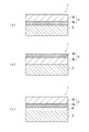
以下、図3を参照して、感光体1が積層型感光体である場合の感光体1の構造について説明する。図3は、本実施形態に係る感光体1の一例である積層型感光体を示す概略断面図である。
<1. Multilayer photoreceptor>
Hereinafter, the structure of the
図3(a)に示すように、感光体1としての積層型感光体は、例えば、導電性基体2と感光層3とを備える。積層型感光体には、感光層3として、電荷発生層3aと電荷輸送層3bとが備えられる。
As shown in FIG. 3A, the laminated photoreceptor as the
図3(b)に示すように、感光体1としての積層型感光体では、導電性基体2上に電荷輸送層3bが設けられ、電荷輸送層3b上に電荷発生層3aが設けられてもよい。ただし、一般に電荷輸送層3bの膜厚は、電荷発生層3aの膜厚に比べ厚いため、電荷輸送層3bは、電荷発生層3aに比べ破損し難い。このため、積層型感光体の耐摩耗性を向上させるためには、図3(a)に示すように、導電性基体2上に電荷発生層3aが設けられ、電荷発生層3a上に電荷輸送層3bが設けられることが好ましい。
As shown in FIG. 3 (b), in the laminated type photoconductor as the
図3(c)に示すように、感光体1としての積層型感光体は、導電性基体2と感光層3と中間層(下引き層)4とを備えていてもよい。中間層4は、導電性基体2と感光層3との間に備えられる。また、感光層3上には、保護層5(図4参照)が設けられていてもよい。
As shown in FIG. 3C, the multilayer photoreceptor as the
電荷発生層3a及び電荷輸送層3bの厚さは、それぞれの層としての機能を十分に発現できる限り、特に限定されない。電荷発生層3aの厚さは、0.01μm以上5μm以下であることが好ましく、0.1μm以上3μm以下であることがより好ましい。電荷輸送層3bの厚さは、2μm以上100μm以下であることが好ましく、5μm以上50μm以下であることがより好ましい。
The thicknesses of the
感光層3のうちの電荷発生層3aは、電荷発生剤を含有する。電荷発生層3aは、電荷発生層用バインダー樹脂(以下、ベース樹脂と記載することがある)を含有してもよい。電荷発生層3aは、必要に応じて、各種添加剤を含有してもよい。
The
感光層3のうちの電荷輸送層3bは、正孔輸送剤を含有する。電荷輸送層3bは、バインダー樹脂を含有してもよい。電荷輸送層3bは、必要に応じて、電子アクセプター化合物及び各種添加剤を含有してもよい。以上、図3を参照して、感光体1が積層型感光体である場合の感光体1の構造について説明した。
The
<2.単層型感光体>
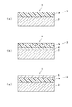
以下、図4を参照して、感光体1が単層型感光体である場合の感光体1の構造について説明する。図4は、本実施形態に係る感光体1の別の例である単層型感光体を示す概略断面図である。
<2. Single-layer type photoreceptor>
Hereinafter, the structure of the
図4(a)に示すように、感光体1としての単層型感光体は、例えば、導電性基体2と感光層3とを備える。感光体1としての単層型感光体には、感光層3として、単層型感光層3cが備えられる。単層型感光層3cは、一層の感光層3である。
As shown in FIG. 4A, the single layer type photoreceptor as the
図4(b)に示すように、感光体1としての単層型感光体は、導電性基体2と、単層型感光層3cと、中間層(下引き層)4とを備えてもよい。中間層4は、導電性基体2と単層型感光層3cとの間に設けられる。また、図4(c)に示すように、単層型感光層3c上に保護層5が設けられてもよい。
As shown in FIG. 4B, the single layer type photoreceptor as the
単層型感光層3cの厚さは、単層型感光層としての機能を十分に発現できる限り、特に限定されない。単層型感光層3cの厚さは、5μm以上100μm以下であることが好ましく、10μm以上50μm以下であることがより好ましい。
The thickness of the single-layer type
感光層3としての単層型感光層3cは、電荷発生剤と正孔輸送剤とを一層に含有する。単層型感光層3cは、電子輸送剤及びバインダー樹脂のうちの一以上を更に含有してもよい。単層型感光層3cは、必要に応じて、各種添加剤を含有してもよい。感光体1が単層型感光体である場合、電荷発生剤と、正孔輸送剤と、必要に応じて添加される成分(例えば、電子輸送剤、バインダー樹脂又は添加剤)とは、一層の感光層3(単層型感光層3c)に含有される。以上、図4を参照して、感光体1が単層型感光体である場合の感光体1の構造について説明した。
The single-layer type
次に、感光体である積層型感光体及び単層型感光体の要素について説明する。 Next, the elements of the multilayer photoreceptor and the single-layer photoreceptor that are photoreceptors will be described.
<3.導電性基体>
導電性基体は、感光体の導電性基体として用いることができる限り、特に限定されない。導電性基体は、少なくとも表面部が導電性を有する材料で形成されていればよい。導電性基体の一例としては、導電性を有する材料で形成される導電性基体が挙げられる。導電性基体の別の例としては、導電性を有する材料で被覆される導電性基体が挙げられる。導電性を有する材料としては、例えば、アルミニウム、鉄、銅、錫、白金、銀、バナジウム、モリブデン、クロム、カドミウム、チタン、ニッケル、パラジウム、インジウム、ステンレス鋼又は真鍮が挙げられる。これらの導電性を有する材料を単独で用いてもよいし、2種以上を組み合わせて(例えば、合金として)用いてもよい。これらの導電性を有する材料のなかでも、感光層から導電性基体への電荷の移動が良好であることから、アルミニウム又はアルミニウム合金が好ましい。
<3. Conductive substrate>
The conductive substrate is not particularly limited as long as it can be used as the conductive substrate of the photoreceptor. The conductive substrate may be formed of a material having at least a surface portion having conductivity. An example of the conductive substrate is a conductive substrate formed of a conductive material. Another example of the conductive substrate is a conductive substrate coated with a conductive material. Examples of the conductive material include aluminum, iron, copper, tin, platinum, silver, vanadium, molybdenum, chromium, cadmium, titanium, nickel, palladium, indium, stainless steel, and brass. These conductive materials may be used alone or in combination of two or more (for example, as an alloy). Among these materials having conductivity, aluminum or an aluminum alloy is preferable because charge transfer from the photosensitive layer to the conductive substrate is good.
導電性基体の形状は、画像形成装置の構造に合わせて適宜選択される。導電性基体の形状としては、例えば、シート状又はドラム状が挙げられる。また、導電性基体の厚さは、導電性基体の形状に応じて適宜選択される。 The shape of the conductive substrate is appropriately selected according to the structure of the image forming apparatus. Examples of the shape of the conductive substrate include a sheet shape or a drum shape. The thickness of the conductive substrate is appropriately selected according to the shape of the conductive substrate.
<4.正孔輸送剤>
感光層は、正孔輸送剤として、第一実施形態に係る化合物(1)を含有する。感光体が積層型感光体である場合、電荷輸送層は、正孔輸送剤として化合物(1)を含有する。感光体が単層型感光体である場合、単層型感光層は、正孔輸送剤として化合物(1)を含有する。感光層に化合物(1)が含有されることにより、第一実施形態で述べたように、感光体の電気特性を向上させることができる。
<4. Hole transport agent>
The photosensitive layer contains the compound (1) according to the first embodiment as a hole transport agent. When the photoreceptor is a multilayer photoreceptor, the charge transport layer contains compound (1) as a hole transport agent. When the photoreceptor is a single layer type photoreceptor, the single layer type photosensitive layer contains the compound (1) as a hole transport agent. By containing the compound (1) in the photosensitive layer, as described in the first embodiment, the electrical characteristics of the photoreceptor can be improved.
感光体が積層型感光体である場合、正孔輸送剤としての化合物(1)の含有量は、電荷輸送層に含有されるバインダー樹脂100質量部に対して、10質量部以上200質量部以下であることが好ましく、20質量部以上100質量部以下であることがより好ましい。 When the photoreceptor is a multilayer photoreceptor, the content of the compound (1) as the hole transport agent is 10 parts by mass or more and 200 parts by mass or less with respect to 100 parts by mass of the binder resin contained in the charge transport layer. It is preferable that it is 20 mass parts or more and 100 mass parts or less.
感光体が単層型感光体である場合、正孔輸送剤としての化合物(1)の含有量は、単層型感光層に含有されるバインダー樹脂100質量部に対して、10質量部以上200質量部以下であることが好ましく、10質量部以上100質量部以下であることがより好ましく、10質量部以上75質量部以下であることが特に好ましい。 When the photoreceptor is a single layer type photoreceptor, the content of the compound (1) as a hole transport agent is 10 parts by mass or more and 200 parts by mass with respect to 100 parts by mass of the binder resin contained in the single layer type photosensitive layer. The mass is preferably 10 parts by mass or more, more preferably 10 parts by mass or more and 100 parts by mass or less, and particularly preferably 10 parts by mass or more and 75 parts by mass or less.
電荷輸送層は、化合物(1)に加えて、更に別の正孔輸送剤を含有してもよい。別の正孔輸送剤としては、例えば、化合物(1)以外の含窒素環式化合物又は縮合多環式化合物を使用することができる。含窒素環式化合物及び縮合多環式化合物としては、例えば、のジアミン化合物(例えば、N,N,N’,N’−テトラフェニルフェニレンジアミン誘導体、N,N,N’,N’−テトラフェニルナフチレンジアミン誘導体又はN,N,N’,N’−テトラフェニルフェナントリレンジアミン誘導体)、オキサジアゾール系化合物(例えば、2,5−ジ(4−メチルアミノフェニル)−1,3,4−オキサジアゾール)、スチリル化合物(例えば、9−(4−ジエチルアミノスチリル)アントラセン)、カルバゾール化合物(例えば、ポリビニルカルバゾール)、有機ポリシラン化合物、ピラゾリン系化合物(例えば、1−フェニル−3−(p−ジメチルアミノフェニル)ピラゾリン)、ヒドラゾン系化合物、インドール系化合物、オキサゾール系化合物、イソオキサゾール系化合物、チアゾール系化合物、チアジアゾール系化合物、イミダゾール系化合物、ピラゾール系化合物又はトリアゾール系化合物が挙げられる。正孔輸送剤の合計質量に対する化合物(1)の含有量は、80質量%以上であることが好ましく、90質量%以上であることが好ましく、100質量%であることが特に好ましい。 The charge transport layer may further contain another hole transport agent in addition to the compound (1). As another hole transport agent, for example, a nitrogen-containing cyclic compound or a condensed polycyclic compound other than the compound (1) can be used. Examples of the nitrogen-containing cyclic compound and the condensed polycyclic compound include diamine compounds (for example, N, N, N ′, N′-tetraphenylphenylenediamine derivatives, N, N, N ′, N′-tetraphenyl). Naphthylenediamine derivatives or N, N, N ′, N′-tetraphenylphenanthrylenediamine derivatives), oxadiazole compounds (for example, 2,5-di (4-methylaminophenyl) -1,3,4 -Oxadiazole), styryl compounds (for example, 9- (4-diethylaminostyryl) anthracene), carbazole compounds (for example, polyvinylcarbazole), organic polysilane compounds, pyrazoline compounds (for example, 1-phenyl-3- (p- Dimethylaminophenyl) pyrazolin), hydrazone compounds, indole compounds, oxazols System compounds, isoxazole compounds, thiazole compounds, thiadiazole compounds, imidazole compounds, pyrazole compound, or triazole-based compounds. The content of the compound (1) with respect to the total mass of the hole transport agent is preferably 80% by mass or more, more preferably 90% by mass or more, and particularly preferably 100% by mass.
<5.電荷発生剤>
感光体が積層型感光体である場合、電荷発生層は、電荷発生剤を含有する。感光体が単層型感光体である場合、単層型感光層は、電荷発生剤を含有する。
<5. Charge generator>
When the photoreceptor is a multilayer photoreceptor, the charge generation layer contains a charge generation agent. When the photoreceptor is a single layer type photoreceptor, the single layer type photosensitive layer contains a charge generating agent.
電荷発生剤は、感光体用の電荷発生剤である限り、特に限定されない。電荷発生剤としては、例えば、フタロシアニン系顔料、ペリレン系顔料、ビスアゾ顔料、トリスアゾ顔料、ジチオケトピロロピロール顔料、無金属ナフタロシアニン顔料、金属ナフタロシアニン顔料、スクアライン顔料、インジゴ顔料、アズレニウム顔料、シアニン顔料、無機光導電材料(例えば、セレン、セレン−テルル、セレン−ヒ素、硫化カドミウム又はアモルファスシリコン)の粉末、ピリリウム顔料、アンサンスロン系顔料、トリフェニルメタン系顔料、スレン系顔料、トルイジン系顔料、ピラゾリン系顔料又はキナクリドン系顔料が挙げられる。電荷発生剤は、1種を単独で用いてもよいし、2種以上を組み合わせて用いてもよい。 The charge generator is not particularly limited as long as it is a charge generator for a photoreceptor. Examples of the charge generator include phthalocyanine pigments, perylene pigments, bisazo pigments, trisazo pigments, dithioketopyrrolopyrrole pigments, metal-free naphthalocyanine pigments, metal naphthalocyanine pigments, squaraine pigments, indigo pigments, azurenium pigments, cyanine Pigments, inorganic photoconductive materials (for example, selenium, selenium-tellurium, selenium-arsenic, cadmium sulfide or amorphous silicon), pyrylium pigments, ansanthrone pigments, triphenylmethane pigments, selenium pigments, toluidine pigments, Examples include pyrazoline pigments and quinacridone pigments. A charge generating agent may be used individually by 1 type, and may be used in combination of 2 or more type.
フタロシアニン系顔料としては、例えば、化学式(C−1)で表される無金属フタロシアニン又は金属フタロシアニンが挙げられる。金属フタロシアニンとしては、例えば、化学式(C−2)で表されるチタニルフタロシアニン、ヒドロキシガリウムフタロシアニン又はクロロガリウムフタロシアニンが挙げられる。フタロシアニン系顔料は、結晶であってもよく、非結晶であってもよい。フタロシアニン系顔料の結晶形状(例えば、α型、β型、Y型、V型又はII型)については特に限定されず、種々の結晶形状を有するフタロシアニン系顔料が使用される。 Examples of the phthalocyanine pigment include metal-free phthalocyanine or metal phthalocyanine represented by the chemical formula (C-1). Examples of the metal phthalocyanine include titanyl phthalocyanine, hydroxygallium phthalocyanine or chlorogallium phthalocyanine represented by the chemical formula (C-2). The phthalocyanine pigment may be crystalline or non-crystalline. The crystal shape of the phthalocyanine pigment (for example, α type, β type, Y type, V type or II type) is not particularly limited, and phthalocyanine pigments having various crystal shapes are used.
無金属フタロシアニンの結晶としては、例えば、無金属フタロシアニンのX型結晶(以下、X型無金属フタロシアニンと記載することがある)が挙げられる。チタニルフタロシアニンの結晶としては、例えば、チタニルフタロシアニンのα型、β型又はY型結晶(以下、α型、β型又はY型チタニルフタロシアニンと記載することがある)が挙げられる。ヒドロキシガリウムフタロシアニンの結晶としては、ヒドロキシガリウムフタロシアニンのV型結晶が挙げられる。クロロガリウムフタロシアニンの結晶としては、クロロガリウムフタロシアニンのII型結晶が挙げられる。 Examples of the crystal of metal-free phthalocyanine include an X-type crystal of metal-free phthalocyanine (hereinafter sometimes referred to as X-type metal-free phthalocyanine). Examples of the crystal of titanyl phthalocyanine include α-type, β-type, and Y-type crystals of titanyl phthalocyanine (hereinafter sometimes referred to as α-type, β-type, or Y-type titanyl phthalocyanine). Examples of the crystal of hydroxygallium phthalocyanine include a V-type crystal of hydroxygallium phthalocyanine. Examples of chlorogallium phthalocyanine crystals include chlorogallium phthalocyanine type II crystals.
例えば、デジタル光学式の画像形成装置(例えば、半導体レーザーのような光源を使用した、レーザービームプリンター又はファクシミリ)には、700nm以上の波長領域に感度を有する感光体を用いることが好ましい。700nm以上の波長領域で高い量子収率を有することから、電荷発生剤としては、フタロシアニン系顔料が好ましく、無金属フタロシアニン又はチタニルフタロシアニンがより好ましく、X型無金属フタロシアニン又はY型チタニルフタロシアニンが更に好ましい。感光層に正孔輸送剤として化合物(1)が含有される場合に電気特性を特に向上させるためには、電荷発生剤としてはY型チタニルフタロシアニンがより好ましい。 For example, in a digital optical image forming apparatus (for example, a laser beam printer or a facsimile using a light source such as a semiconductor laser), it is preferable to use a photoreceptor having sensitivity in a wavelength region of 700 nm or more. Since it has a high quantum yield in a wavelength region of 700 nm or more, the charge generator is preferably a phthalocyanine pigment, more preferably a metal-free phthalocyanine or titanyl phthalocyanine, and even more preferably an X-type metal-free phthalocyanine or Y-type titanyl phthalocyanine. . In order to particularly improve the electrical characteristics when the photosensitive layer contains the compound (1) as a hole transport agent, Y-type titanyl phthalocyanine is more preferable as the charge generator.
Y型チタニルフタロシアニンは、CuKα特性X線回折スペクトルにおいて、例えば、ブラッグ角(2θ±0.2°)の27.2°に主ピークを有する。CuKα特性X線回折スペクトルにおける主ピークとは、ブラッグ角(2θ±0.2°)が3°以上40°以下である範囲において、1番目又は2番目に大きな強度を有するピークである。 Y-type titanyl phthalocyanine has a main peak at 27.2 ° of the Bragg angle (2θ ± 0.2 °) in the CuKα characteristic X-ray diffraction spectrum, for example. The main peak in the CuKα characteristic X-ray diffraction spectrum is a peak having the first or second highest intensity in a range where the Bragg angle (2θ ± 0.2 °) is 3 ° or more and 40 ° or less.
CuKα特性X線回折スペクトルの測定方法の一例について説明する。試料(チタニルフタロシアニン)をX線回折装置(例えば、株式会社リガク製「RINT(登録商標)1100」)のサンプルホルダーに充填して、X線管球Cu、管電圧40kV、管電流30mA、かつCuKα特性X線の波長1.542Åの条件で、X線回折スペクトルを測定する。測定範囲(2θ)は、例えば3°以上40°以下(スタート角3°、ストップ角40°)であり、走査速度は、例えば10°/分である。
An example of a method for measuring the CuKα characteristic X-ray diffraction spectrum will be described. A sample (titanyl phthalocyanine) is filled in a sample holder of an X-ray diffractometer (for example, “RINT (registered trademark) 1100” manufactured by Rigaku Corporation), an X-ray tube Cu, a tube voltage 40 kV, a tube current 30 mA, and CuKα. An X-ray diffraction spectrum is measured under the condition of a characteristic X-ray wavelength of 1.542 mm. The measurement range (2θ) is, for example, 3 ° to 40 ° (start
短波長レーザー光源(例えば、350nm以上550nm以下の波長を有するレーザー光源)を用いた画像形成装置に適用される感光体には、電荷発生剤として、アンサンスロン系顔料が好適に用いられる。 In a photoreceptor applied to an image forming apparatus using a short wavelength laser light source (for example, a laser light source having a wavelength of 350 nm or more and 550 nm or less), an sanslon pigment is preferably used as a charge generating agent.
感光体が積層型感光体である場合、電荷発生剤の含有量は、電荷発生層に含有されるベース樹脂100質量部に対して、5質量部以上1000質量部以下であることが好ましく、30質量部以上500質量部以下であることがより好ましい。 When the photoreceptor is a multilayer photoreceptor, the content of the charge generating agent is preferably 5 parts by mass or more and 1000 parts by mass or less with respect to 100 parts by mass of the base resin contained in the charge generation layer. More preferably, it is at least 500 parts by mass.
感光体が単層型感光体である場合、電荷発生剤の含有量は、単層型感光層に含有されるバインダー樹脂100質量部に対して、0.1質量部以上50質量部以下であることが好ましく、0.5質量部以上30質量部以下であることがより好ましく、0.5質量部以上4.5質量部以下であることが特に好ましい。 When the photoreceptor is a single layer type photoreceptor, the content of the charge generating agent is 0.1 parts by mass or more and 50 parts by mass or less with respect to 100 parts by mass of the binder resin contained in the single layer type photosensitive layer. It is preferably 0.5 parts by mass or more and 30 parts by mass or less, and more preferably 0.5 parts by mass or more and 4.5 parts by mass or less.
<6.電子輸送剤及び電子アクセプター化合物>
感光体が積層型感光体である場合、電荷輸送層は、必要に応じて、電子アクセプター化合物を含有してもよい。これにより、正孔輸送剤の正孔輸送能が向上する傾向がある。一方、感光体が単層型感光体である場合、単層型感光層は、必要に応じて、電子輸送剤を含有してもよい。これにより、単層型感光層は電子を輸送することができ、単層型感光層にバイポーラー(両極性)の特性を付与し易くなる。
<6. Electron Transfer Agent and Electron Acceptor Compound>
When the photoreceptor is a multilayer photoreceptor, the charge transport layer may contain an electron acceptor compound as necessary. Thereby, there exists a tendency for the hole transport ability of a hole transport agent to improve. On the other hand, when the photosensitive member is a single layer type photosensitive member, the single layer type photosensitive layer may contain an electron transport agent, if necessary. Thereby, the single-layer type photosensitive layer can transport electrons, and it becomes easy to impart bipolar (bipolar) characteristics to the single-layer type photosensitive layer.
電子輸送剤又は電子アクセプター化合物の例としては、キノン系化合物、ジイミド系化合物、ヒドラゾン系化合物、マロノニトリル系化合物、チオピラン系化合物、トリニトロチオキサントン系化合物、3,4,5,7−テトラニトロ−9−フルオレノン系化合物、ジニトロアントラセン系化合物、ジニトロアクリジン系化合物、テトラシアノエチレン、2,4,8−トリニトロチオキサントン、ジニトロベンゼン、ジニトロアクリジン、無水コハク酸、無水マレイン酸又はジブロモ無水マレイン酸が挙げられる。キノン系化合物としては、例えば、ジフェノキノン系化合物、アゾキノン系化合物、アントラキノン系化合物、ナフトキノン系化合物、ニトロアントラキノン系化合物又はジニトロアントラキノン系化合物が挙げられる。電子輸送剤は、1種単独で用いてもよいし、2種以上を組み合わせて用いてもよい。電子アクセプター化合物も、1種単独で用いてもよいし、2種以上を組み合わせて用いてもよい。 Examples of electron transfer agents or electron acceptor compounds include quinone compounds, diimide compounds, hydrazone compounds, malononitrile compounds, thiopyran compounds, trinitrothioxanthone compounds, 3,4,5,7-tetranitro-9-. Fluorenone compounds, dinitroanthracene compounds, dinitroacridine compounds, tetracyanoethylene, 2,4,8-trinitrothioxanthone, dinitrobenzene, dinitroacridine, succinic anhydride, maleic anhydride, or dibromomaleic anhydride. Examples of quinone compounds include diphenoquinone compounds, azoquinone compounds, anthraquinone compounds, naphthoquinone compounds, nitroanthraquinone compounds, and dinitroanthraquinone compounds. An electron transfer agent may be used individually by 1 type, and may be used in combination of 2 or more type. An electron acceptor compound may also be used individually by 1 type, and may be used in combination of 2 or more type.
電子輸送剤又は電子アクセプターとしては、例えば、一般式(20)又は(21)で表される化合物が挙げられる。 As an electron transfer agent or an electron acceptor, the compound represented by General formula (20) or (21) is mentioned, for example.
一般式(20)及び(21)中、R20〜R25は、各々独立して、水素原子、シアノ基、置換基を有してもよいアルキル基、置換基を有してもよいアルケニル基、置換基を有してもよいアルコキシ基、置換基を有してもよいアルコキシカルボニル基、置換基を有してもよいアリール基又は置換基を有してもよい複素環基を表す。 In general formulas (20) and (21), R 20 to R 25 are each independently a hydrogen atom, a cyano group, an alkyl group that may have a substituent, or an alkenyl group that may have a substituent. Represents an alkoxy group that may have a substituent, an alkoxycarbonyl group that may have a substituent, an aryl group that may have a substituent, or a heterocyclic group that may have a substituent.
一般式(20)及び(21)中のR20〜R25で表されるアルキル基は、例えば、炭素原子数1以上6以下のアルキル基である。炭素原子数1以上6以下のアルキル基としては、炭素原子数1以上5以下のアルキル基が好ましく、メチル基、tert−ブチル基又は1,1−ジメチルプロピル基がより好ましい。アルキル基は置換基を有してもよい。置換基としては、例えば、ハロゲン原子、ヒドロキシル基、炭素原子数1以上6以下のアルコキシ基、置換基を更に有してもよい炭素原子数6以上14以下のアリール基又はシアノ基が挙げられる。置換基の数は、特に限定されないが、3個以下であることが好ましい。置換基としての炭素原子数6以上14以下のアリール基が更に有する置換基としては、例えば、ハロゲン原子、ヒドロキシル基、炭素原子数1以上6以下のアルキル基、炭素原子数1以上6以下のアルコキシ基、ニトロ基、シアノ基、炭素原子数2以上7以下のアルカノイル基(カルボニル基に炭素原子数1以上6以下のアルキル基が結合した基)、ベンゾイル基、フェノキシ基、炭素原子数2以上7以下のアルコキシカルボニル基(カルボニル基に炭素原子数1以上6以下のアルコキシ基が結合した基)又はフェノキシカルボニル基が挙げられる。 The alkyl group represented by R 20 to R 25 in the general formulas (20) and (21) is, for example, an alkyl group having 1 to 6 carbon atoms. The alkyl group having 1 to 6 carbon atoms is preferably an alkyl group having 1 to 5 carbon atoms, more preferably a methyl group, a tert-butyl group, or a 1,1-dimethylpropyl group. The alkyl group may have a substituent. Examples of the substituent include a halogen atom, a hydroxyl group, an alkoxy group having 1 to 6 carbon atoms, an aryl group having 6 to 14 carbon atoms which may further have a substituent, or a cyano group. The number of substituents is not particularly limited, but is preferably 3 or less. Examples of the substituent further included in the aryl group having 6 to 14 carbon atoms as the substituent include a halogen atom, a hydroxyl group, an alkyl group having 1 to 6 carbon atoms, and an alkoxy having 1 to 6 carbon atoms. Group, nitro group, cyano group, alkanoyl group having 2 to 7 carbon atoms (a group in which an alkyl group having 1 to 6 carbon atoms is bonded to a carbonyl group), benzoyl group, phenoxy group, 2 to 7 carbon atoms Examples include the following alkoxycarbonyl groups (groups in which an alkoxy group having 1 to 6 carbon atoms is bonded to a carbonyl group) or phenoxycarbonyl groups.
一般式(20)及び(21)中のR20〜R25で表されるアルケニル基は、例えば、直鎖状又は分枝鎖状で非置換の炭素原子数2以上6以下のアルケニル基である。炭素原子数2以上6以下のアルケニル基は、例えば、1個以上3個以下の二重結合を有する。炭素原子数2以上6以下のアルケニル基の例としては、ビニル基、プロペニル基、ブテニル基、ペンテニル基、ペンタジエニル基、ヘキセニル基又はヘキサジエニル基が挙げられる。アルケニル基は置換基を有してもよい。置換基としては、例えば、ハロゲン原子、ヒドロキシル基、炭素原子数1以上6以下のアルコキシ基、炭素原子数6以上14以下のアリール基又はシアノ基が挙げられる。置換基の数は、特に限定されないが、3個以下であることが好ましい。 The alkenyl group represented by R 20 to R 25 in the general formulas (20) and (21) is, for example, a linear or branched, unsubstituted alkenyl group having 2 to 6 carbon atoms. . The alkenyl group having 2 to 6 carbon atoms has, for example, 1 to 3 double bonds. Examples of the alkenyl group having 2 to 6 carbon atoms include a vinyl group, a propenyl group, a butenyl group, a pentenyl group, a pentadienyl group, a hexenyl group, and a hexadienyl group. The alkenyl group may have a substituent. Examples of the substituent include a halogen atom, a hydroxyl group, an alkoxy group having 1 to 6 carbon atoms, an aryl group having 6 to 14 carbon atoms, and a cyano group. The number of substituents is not particularly limited, but is preferably 3 or less.
一般式(20)及び(21)中のR20〜R25で表されるアルコキシ基は、例えば、炭素原子数1以上6以下のアルコキシ基である。炭素原子数1以上6以下のアルコキシ基としては、炭素原子数1以上3以下のアルコキシ基が好ましく、メトキシ基がより好ましい。アルコキシ基は置換基を有してもよい。置換基としては、例えば、ハロゲン原子、ヒドロキシル基、炭素原子数1以上6以下のアルコキシ基、炭素原子数6以上14以下のアリール基又はシアノ基が挙げられる。置換基として好ましくは、フェニル基である。置換基の数は、特に限定されないが、3個以下であることが好ましく、1個であることがより好ましい。 The alkoxy group represented by R 20 to R 25 in the general formulas (20) and (21) is, for example, an alkoxy group having 1 to 6 carbon atoms. The alkoxy group having 1 to 6 carbon atoms is preferably an alkoxy group having 1 to 3 carbon atoms, and more preferably a methoxy group. The alkoxy group may have a substituent. Examples of the substituent include a halogen atom, a hydroxyl group, an alkoxy group having 1 to 6 carbon atoms, an aryl group having 6 to 14 carbon atoms, and a cyano group. As the substituent, a phenyl group is preferable. The number of substituents is not particularly limited, but is preferably 3 or less, more preferably 1.
一般式(20)及び(21)中のR20〜R25で表されるアルコキシカルボニル基は、例えば、炭素原子数2以上7以下のアルコキシカルボニル基である。炭素原子数2以上7以下のアルコキシカルボニル基は、カルボニル基に直鎖状又は分枝鎖状で非置換の炭素原子数1以上6以下のアルコキシ基が結合した基である。アルコキシカルボニル基は置換基を有してもよい。置換基としては、例えば、ハロゲン原子、ヒドロキシル基、炭素原子数1以上6以下のアルコキシ基、炭素原子数6以上14以下のアリール基又はシアノ基が挙げられる。置換基の数は、特に限定されないが、3個以下であることが好ましい。 The alkoxycarbonyl group represented by R 20 to R 25 in the general formulas (20) and (21) is, for example, an alkoxycarbonyl group having 2 to 7 carbon atoms. An alkoxycarbonyl group having 2 to 7 carbon atoms is a group in which a linear or branched, unsubstituted alkoxy group having 1 to 6 carbon atoms is bonded to a carbonyl group. The alkoxycarbonyl group may have a substituent. Examples of the substituent include a halogen atom, a hydroxyl group, an alkoxy group having 1 to 6 carbon atoms, an aryl group having 6 to 14 carbon atoms, and a cyano group. The number of substituents is not particularly limited, but is preferably 3 or less.
一般式(20)及び(21)中のR20〜R25で表されるアリール基は、例えば、炭素原子数6以上14以下のアリール基である。炭素原子数6以上14以下のアリール基としては、フェニル基が好ましい。アリール基は置換基を有してもよい。置換基としては、例えば、ハロゲン原子、ヒドロキシル基、炭素原子数1以上6以下のアルキル基、炭素原子数1以上6以下のアルコキシ基、ニトロ基、シアノ基、炭素原子数2以上7以下のアルカノイル基(カルボニル基に炭素原子数1以上6以下のアルキル基が結合した基)、ベンゾイル基、フェノキシ基、炭素原子数2以上7以下のアルコキシカルボニル基(カルボニル基に炭素原子数1以上6以下のアルコキシ基が結合した基)、フェノキシカルボニル基、炭素原子数6以上14以下のアリール基又はビフェニル基が挙げられる。置換基の数は、特に限定されないが、3個以下であることが好ましい。 The aryl group represented by R 20 to R 25 in the general formulas (20) and (21) is, for example, an aryl group having 6 to 14 carbon atoms. The aryl group having 6 to 14 carbon atoms is preferably a phenyl group. The aryl group may have a substituent. Examples of the substituent include a halogen atom, a hydroxyl group, an alkyl group having 1 to 6 carbon atoms, an alkoxy group having 1 to 6 carbon atoms, a nitro group, a cyano group, and an alkanoyl having 2 to 7 carbon atoms. A group (a group in which an alkyl group having 1 to 6 carbon atoms is bonded to a carbonyl group), a benzoyl group, a phenoxy group, an alkoxycarbonyl group having 2 to 7 carbon atoms (a carbonyl group having 1 to 6 carbon atoms) A group to which an alkoxy group is bonded), a phenoxycarbonyl group, an aryl group having 6 to 14 carbon atoms, or a biphenyl group. The number of substituents is not particularly limited, but is preferably 3 or less.
一般式(20)及び(21)中のR20〜R25で表される複素環基は、例えば、N、S及びOからなる群より選択される1以上のヘテロ原子を含む5員又は6員の単環の複素環基;このような単環同士が縮合した複素環基;又は、このような単環と、5員又は6員の炭化水素環とが縮合した複素環基である。複素環基が縮合環である場合、縮合環に含まれる環の数は2個又は3個であることが好ましい。複素環基が有してもよい置換基としては、例えば、ハロゲン原子、ヒドロキシル基、炭素原子数1以上6以下のアルキル基、炭素原子数1以上6以下のアルコキシ基、ニトロ基、シアノ基、炭素原子数2以上7以下のアルカノイル基(カルボニル基に炭素原子数1以上6以下のアルキル基が結合した基)、ベンゾイル基、フェノキシ基、炭素原子数2以上7以下のアルコキシカルボニル基(カルボニル基に炭素原子数1以上6以下のアルコキシ基が結合した基)又はフェノキシカルボニル基が挙げられる。置換基の数は、特に限定されないが、3個以下であることが好ましい。 The heterocyclic group represented by R 20 to R 25 in the general formulas (20) and (21) is, for example, 5-membered or 6 containing one or more heteroatoms selected from the group consisting of N, S and O A monocyclic heterocyclic group having a member; a heterocyclic group in which such single rings are condensed; or a heterocyclic group in which such a single ring is condensed with a 5-membered or 6-membered hydrocarbon ring. When the heterocyclic group is a condensed ring, the number of rings contained in the condensed ring is preferably 2 or 3. Examples of the substituent that the heterocyclic group may have include, for example, a halogen atom, a hydroxyl group, an alkyl group having 1 to 6 carbon atoms, an alkoxy group having 1 to 6 carbon atoms, a nitro group, a cyano group, Alkanoyl group having 2 to 7 carbon atoms (a group in which an alkyl group having 1 to 6 carbon atoms is bonded to a carbonyl group), benzoyl group, phenoxy group, alkoxycarbonyl group having 2 to 7 carbon atoms (carbonyl group) Group having an alkoxy group having 1 to 6 carbon atoms bonded thereto, or a phenoxycarbonyl group. The number of substituents is not particularly limited, but is preferably 3 or less.
一般式(20)で表される化合物の具体例としては、化学式(E−1)で表される化合物が挙げられる。一般式(21)で表される化合物の具体例としては、化学式(E−2)で表される化合物が挙げられる。以下、化学式(E−1)及び(E−2)で表される化合物を各々、化合物(E−1)及び(E−2)と記載することがある。 Specific examples of the compound represented by the general formula (20) include a compound represented by the chemical formula (E-1). Specific examples of the compound represented by the general formula (21) include a compound represented by the chemical formula (E-2). Hereinafter, the compounds represented by the chemical formulas (E-1) and (E-2) may be referred to as compounds (E-1) and (E-2), respectively.
感光体が積層型感光体である場合、電子アクセプター化合物の含有量は、電荷輸送層に含有されるバインダー樹脂100質量部に対して、0.1質量部以上20質量部以下であることが好ましく、0.5質量部以上10質量部以下であることがより好ましい。 When the photoreceptor is a multilayer photoreceptor, the content of the electron acceptor compound is preferably 0.1 parts by mass or more and 20 parts by mass or less with respect to 100 parts by mass of the binder resin contained in the charge transport layer. More preferably, it is 0.5 parts by mass or more and 10 parts by mass or less.
感光体が単層型感光体である場合、電子輸送剤の含有量は、単層型感光層に含有されるバインダー樹脂100質量部に対して、5質量部以上100質量部以下であることが好ましく、10質量部以上80質量部以下であることがより好ましく、30質量部以上50質量部以下であることが特に好ましい。 When the photoreceptor is a single layer type photoreceptor, the content of the electron transport agent is 5 parts by mass or more and 100 parts by mass or less with respect to 100 parts by mass of the binder resin contained in the single layer type photosensitive layer. Preferably, it is 10 to 80 parts by mass, more preferably 30 to 50 parts by mass.
<7.バインダー樹脂>
感光体が積層型感光体である場合、電荷輸送層は、バインダー樹脂を含有する。感光体が単層型感光体である場合、単層型感光層は、バインダー樹脂を含有する。
<7. Binder resin>
When the photoreceptor is a multilayer photoreceptor, the charge transport layer contains a binder resin. When the photoreceptor is a single layer type photoreceptor, the single layer type photosensitive layer contains a binder resin.
バインダー樹脂としては、例えば、熱可塑性樹脂、熱硬化性樹脂又は光硬化性樹脂が挙げられる。熱可塑性樹脂としては、例えば、ポリカーボネート樹脂、ポリアリレート樹脂、スチレン−ブタジエン共重合体、スチレン−アクリロニトリル共重合体、スチレン−マレイン酸共重合体、アクリル酸重合体、スチレン−アクリル酸共重合体、ポリエチレン樹脂、エチレン−酢酸ビニル共重合体、塩素化ポリエチレン樹脂、ポリ塩化ビニル樹脂、ポリプロピレン樹脂、アイオノマー樹脂、塩化ビニル−酢酸ビニル共重合体、アルキド樹脂、ポリアミド樹脂、ウレタン樹脂、ポリスルホン樹脂、ジアリルフタレート樹脂、ケトン樹脂、ポリビニルブチラール樹脂、ポリエステル樹脂又はポリエーテル樹脂が挙げられる。熱硬化性樹脂としては、例えば、シリコーン樹脂、エポキシ樹脂、フェノール樹脂、尿素樹脂又はメラミン樹脂が挙げられる。光硬化性樹脂としては、例えば、エポキシアクリレート(エポキシ化合物のアクリル酸付加物)又はウレタン−アクリレート(ウレタン化合物のアクリル酸付加物)が挙げられる。これらのバインダー樹脂は、1種を単独で使用してもよく、2種以上を組み合わせて使用してもよい。 Examples of the binder resin include a thermoplastic resin, a thermosetting resin, and a photocurable resin. Examples of the thermoplastic resin include polycarbonate resin, polyarylate resin, styrene-butadiene copolymer, styrene-acrylonitrile copolymer, styrene-maleic acid copolymer, acrylic acid polymer, styrene-acrylic acid copolymer, Polyethylene resin, ethylene-vinyl acetate copolymer, chlorinated polyethylene resin, polyvinyl chloride resin, polypropylene resin, ionomer resin, vinyl chloride-vinyl acetate copolymer, alkyd resin, polyamide resin, urethane resin, polysulfone resin, diallyl phthalate Examples thereof include resins, ketone resins, polyvinyl butyral resins, polyester resins, and polyether resins. As a thermosetting resin, a silicone resin, an epoxy resin, a phenol resin, a urea resin, or a melamine resin is mentioned, for example. Examples of the photocurable resin include epoxy acrylate (epoxy compound acrylic acid adduct) or urethane-acrylate (urethane compound acrylic acid adduct). These binder resins may be used individually by 1 type, and may be used in combination of 2 or more type.
これらの樹脂の中では、加工性、機械的特性、光学的特性及び耐摩耗性のバランスに優れた単層型感光層及び電荷輸送層が得られることから、ポリカーボネート樹脂が好ましい。ポリカーボネート樹脂の例としては、下記化学式で表されるビスフェノールZ型ポリカーボネート樹脂、ビスフェノールZC型ポリカーボネート樹脂、ビスフェノールC型ポリカーボネート樹脂又はビスフェノールA型ポリカーボネート樹脂が挙げられる。 Among these resins, a polycarbonate resin is preferable because a single-layer type photosensitive layer and a charge transport layer excellent in balance of workability, mechanical properties, optical properties, and abrasion resistance can be obtained. Examples of the polycarbonate resin include bisphenol Z type polycarbonate resin, bisphenol ZC type polycarbonate resin, bisphenol C type polycarbonate resin and bisphenol A type polycarbonate resin represented by the following chemical formula.
バインダー樹脂の粘度平均分子量は、40,000以上であることが好ましく、40,000以上52,500以下であることがより好ましい。バインダー樹脂の粘度平均分子量が40,000以上であると、感光体の耐摩耗性を向上させ易い。バインダー樹脂の粘度平均分子量が52,500以下であると、感光層の形成時にバインダー樹脂が溶剤に溶解し易くなり、電荷輸送層用塗布液又は単層型感光層用塗布液の粘度が高くなり過ぎない。その結果、電荷輸送層又は単層型感光層を形成し易くなる。 The viscosity average molecular weight of the binder resin is preferably 40,000 or more, and more preferably 40,000 or more and 52,500 or less. When the viscosity average molecular weight of the binder resin is 40,000 or more, it is easy to improve the wear resistance of the photoreceptor. When the viscosity average molecular weight of the binder resin is 52,500 or less, the binder resin is easily dissolved in a solvent during formation of the photosensitive layer, and the viscosity of the charge transport layer coating solution or single layer type photosensitive layer coating solution is increased. Not too much. As a result, it becomes easy to form a charge transport layer or a single-layer type photosensitive layer.
<8.ベース樹脂>
感光体が積層型感光体である場合、電荷発生層は、ベース樹脂を含有する。ベース樹脂は、感光体に適用できるベース樹脂である限り、特に制限されない。ベース樹脂としては、熱可塑性樹脂、熱硬化性樹脂又は光硬化性樹脂が挙げられる。熱可塑性樹脂としては、例えば、スチレン−ブタジエン共重合体、スチレン−アクリロニトリル共重合体、スチレン−マレイン酸共重合体、スチレン−アクリル酸共重合体、アクリル酸重合体、ポリエチレン樹脂、エチレン−酢酸ビニル共重合体、塩素化ポリエチレン樹脂、ポリ塩化ビニル樹脂、ポリプロピレン樹脂、アイオノマー、塩化ビニル−酢酸ビニル共重合体、アルキド樹脂、ポリアミド樹脂、ウレタン樹脂、ポリカーボネート樹脂、ポリアリレート樹脂、ポリスルホン樹脂、ジアリルフタレート樹脂、ケトン樹脂、ポリビニルブチラール樹脂、ポリエーテル樹脂又はポリエステル樹脂が挙げられる。熱硬化性樹脂としては、例えば、シリコーン樹脂、エポキシ樹脂、フェノール樹脂、尿素樹脂、メラミン樹脂又はその他架橋性の熱硬化性樹脂が挙げられる。光硬化性樹脂としては、例えば、エポキシアクリレート(エポキシ化合物のアクリル酸付加物)又はウレタン−アクリレート(ウレタン化合物のアクリル酸付加物)が挙げられる。ベース樹脂は1種を単独で使用してもよいし、2種以上を組み合わせて使用してもよい。
<8. Base resin>
When the photoreceptor is a multilayer photoreceptor, the charge generation layer contains a base resin. The base resin is not particularly limited as long as it is a base resin applicable to the photoreceptor. Examples of the base resin include a thermoplastic resin, a thermosetting resin, and a photocurable resin. Examples of the thermoplastic resin include styrene-butadiene copolymer, styrene-acrylonitrile copolymer, styrene-maleic acid copolymer, styrene-acrylic acid copolymer, acrylic acid polymer, polyethylene resin, ethylene-vinyl acetate. Copolymer, chlorinated polyethylene resin, polyvinyl chloride resin, polypropylene resin, ionomer, vinyl chloride-vinyl acetate copolymer, alkyd resin, polyamide resin, urethane resin, polycarbonate resin, polyarylate resin, polysulfone resin, diallyl phthalate resin , Ketone resin, polyvinyl butyral resin, polyether resin or polyester resin. Examples of the thermosetting resin include silicone resin, epoxy resin, phenol resin, urea resin, melamine resin, and other crosslinkable thermosetting resins. Examples of the photocurable resin include epoxy acrylate (epoxy compound acrylic acid adduct) or urethane-acrylate (urethane compound acrylic acid adduct). A base resin may be used individually by 1 type, and may be used in combination of 2 or more type.
電荷発生層に含有されるベース樹脂は、電荷輸送層に含有されるバインダー樹脂とは異なることが好ましい。積層型感光体の製造では、例えば、導電性基体上に電荷発生層が形成され、電荷発生層上に電荷輸送層が形成される。その際に、電荷発生層上に、電荷輸送層用塗布液が塗布される。そのため、電荷発生層は、電荷輸送層用塗布液の溶剤に溶解しないことが好ましいからである。 The base resin contained in the charge generation layer is preferably different from the binder resin contained in the charge transport layer. In the production of a multilayer photoreceptor, for example, a charge generation layer is formed on a conductive substrate, and a charge transport layer is formed on the charge generation layer. At that time, a charge transport layer coating solution is applied onto the charge generation layer. Therefore, the charge generation layer is preferably not dissolved in the solvent of the charge transport layer coating solution.
<9.添加剤>
感光体の感光層(電荷発生層、電荷輸送層又は単層型感光層)は、必要に応じて、各種の添加剤を含有してもよい。添加剤としては、例えば、劣化防止剤(例えば、酸化防止剤、ラジカル捕捉剤、1重項消光剤又は紫外線吸収剤)、軟化剤、表面改質剤、増量剤、増粘剤、分散安定剤、ワックス、アクセプター、ドナー、界面活性剤、可塑剤、増感剤又はレベリング剤が挙げられる。酸化防止剤としては、例えば、ヒンダードフェノール(例えば、ジ(tert−ブチル)p−クレゾール)、ヒンダードアミン、パラフェニレンジアミン、アリールアルカン、ハイドロキノン、スピロクロマン、スピロインダノン若しくはこれらの誘導体、有機硫黄化合物又は有機燐化合物が挙げられる。
<9. Additives>
The photosensitive layer (charge generation layer, charge transport layer or single layer type photosensitive layer) of the photoreceptor may contain various additives as required. Examples of additives include deterioration inhibitors (for example, antioxidants, radical scavengers, singlet quenchers or ultraviolet absorbers), softeners, surface modifiers, extenders, thickeners, dispersion stabilizers. , Waxes, acceptors, donors, surfactants, plasticizers, sensitizers or leveling agents. Antioxidants include, for example, hindered phenols (eg, di (tert-butyl) p-cresol), hindered amines, paraphenylenediamine, arylalkanes, hydroquinones, spirochromans, spirodanone or derivatives thereof, organic sulfur compounds or An organic phosphorus compound is mentioned.
<10.中間層>
中間層(下引き層)は、例えば、無機粒子及び中間層に用いられる樹脂(中間層用樹脂)を含有する。中間層が存在することにより、リーク発生を抑制し得る程度の絶縁状態を維持しつつ、感光体を露光した時に発生する電流の流れを円滑にして、抵抗の上昇が抑えられると考えられる。
<10. Intermediate layer>
The intermediate layer (undercoat layer) contains, for example, inorganic particles and a resin (intermediate layer resin) used for the intermediate layer. The presence of the intermediate layer is considered to suppress the increase in resistance by smoothing the flow of current generated when the photosensitive member is exposed while maintaining an insulating state capable of suppressing the occurrence of leakage.
無機粒子としては、例えば、金属(例えば、アルミニウム、鉄又は銅)、金属酸化物(例えば、酸化チタン、アルミナ、酸化ジルコニウム、酸化スズ又は酸化亜鉛)の粒子又は非金属酸化物(例えば、シリカ)の粒子が挙げられる。これらの無機粒子は、1種を単独で用いてもよいし、2種以上を併用してもよい。 Examples of the inorganic particles include metal (for example, aluminum, iron or copper), metal oxide (for example, titanium oxide, alumina, zirconium oxide, tin oxide or zinc oxide) particles or non-metal oxide (for example, silica). Particles. These inorganic particles may be used individually by 1 type, and may use 2 or more types together.
中間層用樹脂としては、中間層を形成する樹脂として用いることができる限り、特に限定されない。中間層は、各種の添加剤を含有してもよい。添加剤は、感光層の添加剤と同様である。 The resin for the intermediate layer is not particularly limited as long as it can be used as a resin for forming the intermediate layer. The intermediate layer may contain various additives. The additive is the same as the additive for the photosensitive layer.
<11.感光体の製造方法>
感光体が積層型感光体である場合、積層型感光体は、例えば、以下のように製造される。まず、電荷発生層用塗布液及び電荷輸送層用塗布液を調製する。電荷発生層用塗布液を導電性基体上に塗布し、乾燥することによって、電荷発生層を形成する。続いて、電荷輸送層用塗布液を電荷発生層上に塗布し、乾燥することによって、電荷輸送層を形成する。これにより、積層型感光体が製造される。
<11. Photoconductor manufacturing method>
When the photoreceptor is a multilayer photoreceptor, the multilayer photoreceptor is manufactured, for example, as follows. First, a charge generation layer coating solution and a charge transport layer coating solution are prepared. A charge generation layer is formed by applying a coating solution for charge generation layer onto a conductive substrate and drying. Subsequently, the charge transport layer coating liquid is applied on the charge generation layer and dried to form the charge transport layer. Thereby, a laminated photoreceptor is manufactured.
電荷発生層用塗布液は、電荷発生剤及び必要に応じて添加される成分(例えば、ベース樹脂及び各種の添加剤)を、溶剤に溶解又は分散させることにより調製される。電荷輸送層用塗布液は、正孔輸送剤及び必要に応じて添加される成分(例えば、バインダー樹脂、電子アクセプター化合物及び各種添加剤)を、溶剤に溶解又は分散させることにより調製される。 The coating solution for the charge generation layer is prepared by dissolving or dispersing the charge generation agent and components added as necessary (for example, base resin and various additives) in a solvent. The coating solution for the charge transport layer is prepared by dissolving or dispersing a hole transport agent and components added as necessary (for example, a binder resin, an electron acceptor compound, and various additives) in a solvent.
次に、感光体が単層型感光体である場合、単層型感光体は、例えば、以下のように製造される。単層型感光体は、単層型感光層用塗布液を導電性基体上に塗布し、乾燥することによって製造される。単層型感光層用塗布液は、電荷発生剤、正孔輸送剤及び必要に応じて添加される成分(例えば、電子輸送剤、バインダー樹脂及び各種添加剤)を、溶剤に溶解又は分散させることにより製造される。 Next, when the photoconductor is a single layer type photoconductor, the single layer type photoconductor is manufactured, for example, as follows. The single-layer type photoreceptor is manufactured by applying a coating solution for a single-layer type photosensitive layer onto a conductive substrate and drying it. The coating solution for a single-layer type photosensitive layer is obtained by dissolving or dispersing a charge generating agent, a hole transporting agent and components added as necessary (for example, an electron transporting agent, a binder resin and various additives) in a solvent. Manufactured by.
塗布液(電荷発生層用塗布液、電荷輸送層用塗布液又は単層型感光層用塗布液)に含有される溶剤は、塗布液に含まれる各成分を溶解又は分散できる限り、特に限定されない。溶剤の例としては、アルコール類(例えば、メタノール、エタノール、イソプロパノール又はブタノール)、脂肪族炭化水素(例えば、n−ヘキサン、オクタン又はシクロヘキサン)、芳香族炭化水素(例えば、ベンゼン、トルエン又はキシレン)、ハロゲン化炭化水素(例えば、ジクロロメタン、ジクロロエタン、四塩化炭素又はクロロベンゼン)、エーテル類(例えば、ジメチルエーテル、ジエチルエーテル、テトラヒドロフラン、エチレングリコールジメチルエーテル、ジエチレングリコールジメチルエーテル又はプロピレングリコールモノメチルエーテル)、ケトン類(例えば、アセトン、メチルエチルケトン又はシクロヘキサノン)、エステル類(例えば、酢酸エチル又は酢酸メチル)、ジメチルホルムアルデヒド、ジメチルホルムアミド又はジメチルスルホキシドが挙げられる。これらの溶剤は、1種単独で又は2種以上を組み合わせて用いられる。感光体の製造時の作業性を向上させるためには、溶剤として非ハロゲン溶剤(ハロゲン化炭化水素以外の溶剤)を用いることが好ましい。 The solvent contained in the coating solution (charge generating layer coating solution, charge transport layer coating solution or single layer type photosensitive layer coating solution) is not particularly limited as long as each component contained in the coating solution can be dissolved or dispersed. . Examples of solvents include alcohols (eg, methanol, ethanol, isopropanol or butanol), aliphatic hydrocarbons (eg, n-hexane, octane or cyclohexane), aromatic hydrocarbons (eg, benzene, toluene or xylene), Halogenated hydrocarbons (eg dichloromethane, dichloroethane, carbon tetrachloride or chlorobenzene), ethers (eg dimethyl ether, diethyl ether, tetrahydrofuran, ethylene glycol dimethyl ether, diethylene glycol dimethyl ether or propylene glycol monomethyl ether), ketones (eg acetone, Methyl ethyl ketone or cyclohexanone), esters (eg ethyl acetate or methyl acetate), dimethylformaldehyde, dimethylform Amide or dimethyl sulfoxide. These solvents are used alone or in combination of two or more. In order to improve the workability during the production of the photoreceptor, it is preferable to use a non-halogen solvent (a solvent other than the halogenated hydrocarbon) as the solvent.
塗布液は、各成分を混合し、溶剤に分散することにより調製される。混合又は分散には、例えば、ビーズミル、ロールミル、ボールミル、アトライター、ペイントシェーカー又は超音波分散機を用いることができる。 The coating solution is prepared by mixing each component and dispersing in a solvent. For mixing or dispersing, for example, a bead mill, a roll mill, a ball mill, an attritor, a paint shaker, or an ultrasonic disperser can be used.
塗布液(電荷発生層用塗布液、電荷輸送層用塗布液又は単層型感光層用塗布液)は、各成分の分散性を向上させるために、例えば、界面活性剤を含有してもよい。 The coating solution (charge generating layer coating solution, charge transport layer coating solution or single layer photosensitive layer coating solution) may contain, for example, a surfactant in order to improve the dispersibility of each component. .
塗布液(電荷発生層用塗布液、電荷輸送層用塗布液又は単層型感光層用塗布液)を塗布する方法としては、塗布液を導電性基体上に均一に塗布できる方法である限り、特に限定されない。塗布方法としては、例えば、ディップコート法、スプレーコート法、スピンコート法又はバーコート法が挙げられる。 As a method of applying a coating solution (a coating solution for a charge generation layer, a coating solution for a charge transport layer or a coating solution for a single-layer type photosensitive layer), as long as the coating solution can be uniformly applied on a conductive substrate, There is no particular limitation. Examples of the coating method include a dip coating method, a spray coating method, a spin coating method, and a bar coating method.
塗布液(電荷発生層用塗布液、電荷輸送層用塗布液又は単層型感光層用塗布液)を乾燥する方法としては、塗布液中の溶剤を蒸発させ得る限り、特に限定されない。例えば、高温乾燥機又は減圧乾燥機を用いて、熱処理(熱風乾燥)する方法が挙げられる。熱処理条件は、例えば、40℃以上150℃以下の温度、かつ3分間以上120分間以下の時間である。 The method for drying the coating solution (charge generating layer coating solution, charge transport layer coating solution or single layer type photosensitive layer coating solution) is not particularly limited as long as the solvent in the coating solution can be evaporated. For example, the method of heat-processing (hot-air drying) is mentioned using a high-temperature dryer or a vacuum dryer. The heat treatment conditions are, for example, a temperature of 40 ° C. or higher and 150 ° C. or lower and a time of 3 minutes or longer and 120 minutes or shorter.
なお、感光体の製造方法は、必要に応じて、中間層を形成する工程及び保護層を形成する工程の一方又は両方を更に含んでもよい。中間層を形成する工程及び保護層を形成する工程では、公知の方法が適宜選択される。 In addition, the manufacturing method of a photoreceptor may further include one or both of a step of forming an intermediate layer and a step of forming a protective layer as necessary. A known method is appropriately selected in the step of forming the intermediate layer and the step of forming the protective layer.
以下、実施例を用いて本発明を更に具体的に説明する。しかし、本発明は実施例の範囲に何ら限定されない。 Hereinafter, the present invention will be described more specifically with reference to examples. However, the present invention is not limited to the scope of the examples.
<1.感光体の材料>
積層型感光体の電荷発生層及び電荷輸送層を形成するための材料として、以下の正孔輸送剤及び電荷発生剤を準備した。単層型感光体の単層型感光層を形成するための材料として、以下の正孔輸送剤、電荷発生剤及び電子輸送剤を準備した。
<1. Photosensitive Material>
The following hole transporting agent and charge generating agent were prepared as materials for forming the charge generating layer and charge transporting layer of the multilayer photoreceptor. The following hole transporting agent, charge generating agent and electron transporting agent were prepared as materials for forming the single layer type photosensitive layer of the single layer type photoreceptor.
<1−1.正孔輸送剤>
正孔輸送剤として、第一実施形態で述べた化合物(H−1)〜(H−5)を準備した。化合物(H−1)〜(H−5)は、各々以下の方法で製造した。
<1-1. Hole transport agent>
As hole transporting agents, the compounds (H-1) to (H-5) described in the first embodiment were prepared. Compounds (H-1) to (H-5) were each produced by the following method.
<1−1−1.化合物(6a)〜(6c)の製造>
まず、化合物(H−1)〜(H−5)を製造するための原料として、化合物(6a)〜(6c)を製造した。下記反応(R−11)及び(R−12)に従って、化合物(6c)を製造した。下記反応(R−11)及び(R−13)に従って、化合物(6a)を製造した。下記反応(R−14)及び(R−15)に従って、化合物(6b)を製造した。
<1-1-1. Production of Compounds (6a) to (6c)>
First, compounds (6a) to (6c) were produced as raw materials for producing compounds (H-1) to (H-5). Compound (6c) was produced according to the following reactions (R-11) and (R-12). Compound (6a) was produced according to the following reactions (R-11) and (R-13). Compound (6b) was produced according to the following reactions (R-14) and (R-15).
反応(R−11)では、化合物(2a)と亜リン酸トリエチルとを反応させて、化合物(3a)を得た。詳しくは、容量200mLのフラスコに、化合物(2a)16.1g(0.10モル)と、亜リン酸トリエチル25.0g(0.15モル)とを投入した。フラスコ内容物を、180℃で8時間攪拌した後、室温まで冷却した。続いて、フラスコ内容物に含まれる未反応の亜リン酸トリエチルを減圧留去した。これにより、白色液体である化合物(3a)を得た。化合物(3a)の収量は24.1gであり、化合物(2a)からの化合物(3a)の収率は92mol%であった。 In reaction (R-11), compound (3a) was obtained by reacting compound (2a) with triethyl phosphite. Specifically, 16.1 g (0.10 mol) of the compound (2a) and 25.0 g (0.15 mol) of triethyl phosphite were charged into a 200-mL flask. The flask contents were stirred at 180 ° C. for 8 hours and then cooled to room temperature. Subsequently, unreacted triethyl phosphite contained in the flask contents was distilled off under reduced pressure. This obtained the compound (3a) which is a white liquid. The yield of compound (3a) was 24.1 g, and the yield of compound (3a) from compound (2a) was 92 mol%.
反応(R−12)では、化合物(3a)と化合物(4a)とを反応させて化合物(6c)を得た。反応(R−12)は、ウィッティヒ(Wittig)反応である。詳しくは、反応(R−11)で得られた化合物(3a)13.1g(0.05モル)を、容量500mLの二口フラスコに0℃で加えた。フラスコ内の空気を、アルゴンガスで置換した。続いて、フラスコ内に、乾燥テトラヒドロフラン(100mL)及び28%ナトリウムメトキシド9.3g(0.05モル)を添加した。フラスコ内容物を30分間攪拌した。続いて、フラスコ内に、化合物(4a)7.0g(0.05モル)の乾燥テトラヒドロフラン(300mL)溶液を添加した。フラスコ内容物を、室温で12時間攪拌した。フラスコ内容物を、イオン交換水に注ぎ、トルエンで抽出した。得られた有機層を、イオン交換水で5回洗浄し、無水硫酸ナトリウムを用いて乾燥させた。続いて、有機層に含有される溶媒を留去し、残渣を得た。得られた残渣を、トルエン/メタノール(20mL/100mL)を用いて晶析した。これにより、化合物(6c)を得た。化合物(6c)の収量は9.4gであり、化合物(3a)からの化合物(6c)の収率は75mol%であった。 In reaction (R-12), compound (3a) was reacted with compound (4a) to give compound (6c). Reaction (R-12) is a Wittig reaction. Specifically, 13.1 g (0.05 mol) of the compound (3a) obtained in the reaction (R-11) was added to a two-necked flask having a volume of 500 mL at 0 ° C. The air in the flask was replaced with argon gas. Subsequently, dry tetrahydrofuran (100 mL) and 9.3 g (0.05 mol) of 28% sodium methoxide were added to the flask. The flask contents were stirred for 30 minutes. Subsequently, a solution of 7.0 g (0.05 mol) of compound (4a) in dry tetrahydrofuran (300 mL) was added to the flask. The flask contents were stirred at room temperature for 12 hours. The contents of the flask were poured into ion exchange water and extracted with toluene. The obtained organic layer was washed 5 times with ion-exchanged water and dried using anhydrous sodium sulfate. Subsequently, the solvent contained in the organic layer was distilled off to obtain a residue. The obtained residue was crystallized using toluene / methanol (20 mL / 100 mL). This obtained the compound (6c). The yield of compound (6c) was 9.4 g, and the yield of compound (6c) from compound (3a) was 75 mol%.
反応(R−13)では、化合物(3a)と化合物(5a)とを反応させて化合物(6a)を得た。反応(R−13)は、ウィッティヒ(Wittig)反応である。詳しくは、反応(R−11)で得られた化合物(3a)13.1g(0.05モル)を、容量500mLの二口フラスコに0℃で加えた。フラスコ内の空気を、アルゴンガスで置換した。続いて、フラスコ内に、乾燥テトラヒドロフラン(100mL)及び28%ナトリウムメトキシド9.3g(0.05モル)を添加した。フラスコ内容物を30分間攪拌した。続いて、フラスコ内に、化合物(5a)8.4g(0.05モル)の乾燥テトラヒドロフラン(300mL)溶液を添加した。フラスコ内容物を、室温で12時間攪拌した。フラスコ内容物を、イオン交換水に注ぎ、トルエンで抽出した。得られた有機層を、イオン交換水で5回洗浄し、無水硫酸ナトリウムを用いて乾燥させた。続いて、有機層に含有される溶媒を留去し、残渣を得た。得られた残渣を、トルエン/メタノール(20mL/100mL)を用いて晶析した。これにより、白色結晶である化合物(6a)を得た。化合物(6a)の収量は9.6gであり、化合物(3a)からの化合物(6a)の収率は69mol%であった。 In the reaction (R-13), the compound (3a) and the compound (5a) were reacted to obtain the compound (6a). Reaction (R-13) is a Wittig reaction. Specifically, 13.1 g (0.05 mol) of the compound (3a) obtained in the reaction (R-11) was added to a two-necked flask having a volume of 500 mL at 0 ° C. The air in the flask was replaced with argon gas. Subsequently, dry tetrahydrofuran (100 mL) and 9.3 g (0.05 mol) of 28% sodium methoxide were added to the flask. The flask contents were stirred for 30 minutes. Subsequently, a solution of 8.4 g (0.05 mol) of compound (5a) in dry tetrahydrofuran (300 mL) was added to the flask. The flask contents were stirred at room temperature for 12 hours. The contents of the flask were poured into ion exchange water and extracted with toluene. The obtained organic layer was washed 5 times with ion-exchanged water and dried using anhydrous sodium sulfate. Subsequently, the solvent contained in the organic layer was distilled off to obtain a residue. The obtained residue was crystallized using toluene / methanol (20 mL / 100 mL). This obtained the compound (6a) which is a white crystal. The yield of compound (6a) was 9.6 g, and the yield of compound (6a) from compound (3a) was 69 mol%.
反応(R−14)では、化合物(7a)と亜リン酸トリエチルとを反応させて、化合物(8)を得た。詳しくは、容量200mLのフラスコに、化合物(7a)15.2g(0.05モル)と、亜リン酸トリエチル25.0g(0.15モル)とを投入した。フラスコ内容物を、180℃で8時間攪拌した後、室温まで冷却した。続いて、フラスコ内容物に含まれる未反応の亜リン酸トリエチルを減圧留去した。これにより、化合物(8)を得た。化合物(8)の収量は14.5gであり、化合物(7a)からの化合物(8)の収率は88mol%であった。 In reaction (R-14), compound (7a) was reacted with triethyl phosphite to obtain compound (8). Specifically, 15.2 g (0.05 mol) of the compound (7a) and 25.0 g (0.15 mol) of triethyl phosphite were charged into a 200-mL flask. The flask contents were stirred at 180 ° C. for 8 hours and then cooled to room temperature. Subsequently, unreacted triethyl phosphite contained in the flask contents was distilled off under reduced pressure. This obtained compound (8). The yield of compound (8) was 14.5 g, and the yield of compound (8) from compound (7a) was 88 mol%.
反応(R−15)では、化合物(8)と化合物(4a)とを反応させて化合物(6b)を得た。反応(R−15)は、ウィッティヒ(Wittig)反応である。詳しくは、反応(R−14)で得られた化合物(8)16.4g(0.05モル)を、容量500mLの二口フラスコに0℃で加えた。フラスコ内の空気を、アルゴンガスで置換した。続いて、フラスコ内に、乾燥テトラヒドロフラン(100mL)及び28%ナトリウムメトキシド9.3g(0.05モル)を添加した。フラスコ内容物を30分間攪拌した。続いて、フラスコ内に、化合物(4a)14.1g(0.10モル)の乾燥テトラヒドロフラン(300mL)溶液を添加した。フラスコ内容物を、室温で12時間攪拌した。フラスコ内容物を、イオン交換水に注ぎ、トルエンで抽出した。得られた有機層を、イオン交換水で5回洗浄し、無水硫酸ナトリウムを用いて乾燥させた。続いて、有機層に含有される溶媒を留去し、残渣を得た。得られた残渣を、トルエン/メタノール(20mL/100mL)を用いて晶析した。これにより、化合物(6b)を得た。化合物(6b)の収量は3.8gであり、化合物(8)からの化合物(6b)の収率は25mol%であった。 In the reaction (R-15), the compound (8) and the compound (4a) were reacted to obtain the compound (6b). Reaction (R-15) is a Wittig reaction. Specifically, 16.4 g (0.05 mol) of the compound (8) obtained in the reaction (R-14) was added to a 500 mL two-necked flask at 0 ° C. The air in the flask was replaced with argon gas. Subsequently, dry tetrahydrofuran (100 mL) and 9.3 g (0.05 mol) of 28% sodium methoxide were added to the flask. The flask contents were stirred for 30 minutes. Subsequently, a dry tetrahydrofuran (300 mL) solution of 14.1 g (0.10 mol) of the compound (4a) was added to the flask. The flask contents were stirred at room temperature for 12 hours. The contents of the flask were poured into ion exchange water and extracted with toluene. The obtained organic layer was washed 5 times with ion-exchanged water and dried using anhydrous sodium sulfate. Subsequently, the solvent contained in the organic layer was distilled off to obtain a residue. The obtained residue was crystallized using toluene / methanol (20 mL / 100 mL). This obtained the compound (6b). The yield of compound (6b) was 3.8 g, and the yield of compound (6b) from compound (8) was 25 mol%.
<1−1−2.化合物(12a)及び(12b)の製造>
次に、化合物(14a)〜(14e)を製造するための原料として、化合物(12a)及び(12b)を製造した。下記反応(R−16)に従って、化合物(12a)を製造した。下記反応(R−17)に従って、化合物(12b)を製造した。
<1-1-2. Production of Compounds (12a) and (12b)>
Next, compounds (12a) and (12b) were produced as raw materials for producing the compounds (14a) to (14e). Compound (12a) was produced according to the following reaction (R-16). Compound (12b) was produced according to the following reaction (R-17).
反応(R−16)では、化合物(10a)と化合物(11a)とを反応させて化合物(12a)を得た。詳しくは、ディーン・スターク管に、化合物(10a)6.3g(0.0450モル)、化合物(11a、ジフェニルヒドラジン塩酸塩)10.0g(0.0450モル)、トルエン(100mL)及びp−トルエンスルホン酸(0.0045モル)を加えた。混合物を、100℃で4時間還流しながら攪拌した。得られた混合物を、イオン交換水に注ぎ、トルエンで抽出した。得られた有機層を、イオン交換水で5回洗浄し、無水硫酸ナトリウムで乾燥した後、溶媒を留去した。得られた残渣を、トルエン/メタノール(体積比1:1)で晶析し、白色結晶である化合物(12a)を得た。化合物(12a)の収量は12.1gであり、化合物(10a)からの化合物(12a)の収率は88mol%であった。 In the reaction (R-16), the compound (12a) was obtained by reacting the compound (10a) with the compound (11a). Specifically, 6.3 g (0.0450 mol) of the compound (10a), 10.0 g (0.0450 mol) of the compound (11a, diphenylhydrazine hydrochloride), toluene (100 mL) and p-toluene were added to the Dean-Stark tube. Sulfonic acid (0.0045 mol) was added. The mixture was stirred at reflux at 100 ° C. for 4 hours. The resulting mixture was poured into ion exchange water and extracted with toluene. The obtained organic layer was washed 5 times with ion exchange water and dried over anhydrous sodium sulfate, and then the solvent was distilled off. The obtained residue was crystallized from toluene / methanol (volume ratio 1: 1) to obtain a compound (12a) as white crystals. The yield of the compound (12a) was 12.1 g, and the yield of the compound (12a) from the compound (10a) was 88 mol%.
反応(R−17)では、化合物(10b)と化合物(11a)とを反応させて化合物(12b)を得た。反応(R−17)は、化合物(10a)6.3g(0.0450モル)の代わりに化合物(10b)7.5g(0.0450モル)を使用した以外は、反応(R−16)と同様の方法で行った。その結果、化合物(12b)が得られた。化合物(12b)の収量は11.8gであり、化合物(10b)からの化合物(12b)の収率は79mol%であった。 In the reaction (R-17), the compound (10b) and the compound (11a) were reacted to obtain the compound (12b). Reaction (R-17) was carried out in the same manner as reaction (R-16) except that 7.5 g (0.0450 mol) of compound (10b) was used instead of 6.3 g (0.0450 mol) of compound (10a). The same method was used. As a result, compound (12b) was obtained. The yield of compound (12b) was 11.8 g, and the yield of compound (12b) from compound (10b) was 79 mol%.
<1−1−3.化合物(14a)〜(14e)の製造>
次に、下記反応(R−18)に従って、化合物(14a)を製造した。
<1-1-3. Production of Compounds (14a) to (14e)>
Next, compound (14a) was produced according to the following reaction (R-18).
反応(R−18)では、化合物(12a)と化合物(13a)とを反応させて化合物(14a)を得た。以下、化合物(12a)を反応(R−18)の第一原料と、化合物(13a)を反応(R−18)の第二原料と記載することがある。反応(R−18)は、カップリング反応である。詳しくは、三口フラスコに、化合物(12a)6.1g(0.020モル)、トリシクロヘキシルホスフィン0.0662g(1.89×10⁻⁴モル)、トリス(ジベンジリデンアセトン)ジパラジウム(0)0.0864g(9.44×10⁻⁵モル)、ナトリウムtert−ブトキシド4.0g(0.042モル)、化合物(13a)2.1g(0.020モル)及び蒸留したо−キシレン(500mL)を投入した。フラスコ内の空気をアルゴンガスで置換した。続いて、フラスコ内容物を120℃で5時間攪拌した後、室温まで冷却した。フラスコ内容物をイオン交換水で3回洗浄し、有機層を得た。有機層に無水硫酸ナトリウムと活性白土とを加え、乾燥処理及び吸着処理を行った。乾燥処理及び吸着処理後の有機層を減圧留去し、о−キシレンを除去した。これにより、残渣を得た。得られた残渣を、クロロホルム/ヘキサン(体積比1:1)を用いて晶析した。これにより、反応(R−18)の反応生成物として化合物(14a)が得られた。化合物(14a)の収量は5.1gであり、化合物(12a)からの化合物(14a)の収率は69mol%であった。 In the reaction (R-18), the compound (12a) and the compound (13a) were reacted to obtain the compound (14a). Hereinafter, the compound (12a) may be described as a first raw material for the reaction (R-18), and the compound (13a) may be described as a second raw material for the reaction (R-18). Reaction (R-18) is a coupling reaction. Specifically, in a three-necked flask, 6.1 g (0.020 mol) of the compound (12a), 0.0662 g (1.89 × 10 −4 mol) of tricyclohexylphosphine, tris (dibenzylideneacetone) dipalladium (0) 0 0.0864 g (9.44 × 10 −5 mol), sodium tert-butoxide 4.0 g (0.042 mol), compound (13a) 2.1 g (0.020 mol) and distilled о-xylene (500 mL). I put it in. The air in the flask was replaced with argon gas. Subsequently, the flask contents were stirred at 120 ° C. for 5 hours and then cooled to room temperature. The contents of the flask were washed with ion exchange water three times to obtain an organic layer. Anhydrous sodium sulfate and activated clay were added to the organic layer, followed by drying treatment and adsorption treatment. The organic layer after drying treatment and adsorption treatment was distilled off under reduced pressure to remove о-xylene. This gave a residue. The obtained residue was crystallized using chloroform / hexane (volume ratio 1: 1). Thereby, a compound (14a) was obtained as a reaction product of the reaction (R-18). The yield of compound (14a) was 5.1 g, and the yield of compound (14a) from compound (12a) was 69 mol%.
以下の点を変更した以外は、化合物(14a)の製造と同様の方法で、化合物(14b)〜(14e)を各々製造した。なお、化合物(14b)〜(14e)の製造において使用される各原料は、化合物(14a)の製造において使用される対応する原料のモル数と同じモル数で添加した。 Compounds (14b) to (14e) were produced in the same manner as in the production of compound (14a) except that the following points were changed. In addition, each raw material used in manufacture of compound (14b)-(14e) was added by the same mole number as the mole number of the corresponding raw material used in manufacture of compound (14a).
反応(R−18)の第一原料を、化合物(H−1)の製造における化合物(12a)から、表1に示す第一原料(化合物(12a)又は(12b))に変更した。反応(R−18)の第二原料を、化合物(H−1)の製造における化合物(13a)から、表1に示す第二原料(化合物(13b)、(13c)、(13d)又は(13e))に変更した。その結果、反応(R−18)の反応生成物として、化合物(14a)の代わりに、化合物(14b)、(14c)、(14d)及び(14e)の何れかが得られた。反応(R−18)で得られた化合物(14b)、(14c)、(14d)及び(14e)の収量を表1に示す。また、第一原料(化合物(12a)又は(12b))からの化合物(14b)、(14c)、(14d)及び(14e)の収率を表1に示す。 The first raw material for the reaction (R-18) was changed from the compound (12a) in the production of the compound (H-1) to the first raw material (compound (12a) or (12b)) shown in Table 1. The second raw material for the reaction (R-18) is converted from the compound (13a) in the production of the compound (H-1) to the second raw material (compound (13b), (13c), (13d) or (13e) shown in Table 1. )). As a result, any one of the compounds (14b), (14c), (14d) and (14e) was obtained as a reaction product of the reaction (R-18) instead of the compound (14a). Table 1 shows the yields of the compounds (14b), (14c), (14d) and (14e) obtained in the reaction (R-18). Table 1 shows the yields of the compounds (14b), (14c), (14d) and (14e) from the first raw material (compound (12a) or (12b)).
表1中、化合物(12a)及び(12b)、(13a)〜(13e)、並びに(14a)〜(14e)は、各々、下記化学式(12a)及び(12b)、(13a)〜(13e)、並びに(14a)〜(14e)で表される。 In Table 1, compounds (12a) and (12b), (13a) to (13e), and (14a) to (14e) are represented by the following chemical formulas (12a) and (12b), (13a) to (13e), respectively. And (14a) to (14e).
<1−1−4.化合物(H−1)〜(H−5)の製造>
次に、下記反応(R−19)に従って、化合物(H−1)を製造した。
<1-1-4. Production of Compounds (H-1) to (H-5)>
Next, compound (H-1) was produced according to the following reaction (R-19).
反応(R−19)では、化合物(6a)と化合物(14a)とを反応させて化合物(H−1)を得た。以下、化合物(6a)を反応(R−19)の第一原料と、化合物(14a)を反応(R−19)の第二原料と記載することがある。反応(R−19)は、カップリング反応である。詳しくは、三口フラスコに、反応(R−13)で得られた化合物(6a)1.40g(0.005モル)、トリシクロヘキシルホスフィン0.0356g(1.02×10⁻⁴モル)、トリス(ジベンジリデンアセトン)ジパラジウム(0)0.0465g(5.09×10⁻⁵モル)、ナトリウムtert−ブトキシド1.00g(0.010モル)、反応(R−18)で得られた化合物(14a)3.60g(0.010モル)及び蒸留したо−キシレン(200mL)を投入した。フラスコ内の空気をアルゴンガスで置換した。続いて、フラスコ内容物を120℃で5時間攪拌した後、室温まで冷却した。フラスコ内容物をイオン交換水で3回洗浄し、有機層を得た。有機層に無水硫酸ナトリウムと活性白土とを加え、乾燥処理及び吸着処理を行った。乾燥処理及び吸着処理後の有機層を減圧留去し、о−キシレンを除去した。これにより、残渣を得た。得られた残渣を、クロロホルム/ヘキサン(体積比1:1)を用いて晶析した。その結果、化合物(H−1)が得られた。化合物(H−1)の収量は3.2gであり、化合物(6a)からの化合物(H−1)の収率は66mol%であった。 In reaction (R-19), compound (6a) was reacted with compound (14a) to give compound (H-1). Hereinafter, the compound (6a) may be described as a first raw material for the reaction (R-19), and the compound (14a) may be described as a second raw material for the reaction (R-19). Reaction (R-19) is a coupling reaction. Specifically, in a three-necked flask, 1.40 g (0.005 mol) of the compound (6a) obtained in the reaction (R-13), 0.0356 g (1.02 × 10 −4 mol) of tricyclohexylphosphine, tris ( Dibenzylideneacetone) dipalladium (0) 0.0465 g (5.09 × 10 −5 mol), sodium tert-butoxide 1.00 g (0.010 mol), compound (14a) obtained by reaction (R-18) 3.60 g (0.010 mol) and distilled о-xylene (200 mL) were charged. The air in the flask was replaced with argon gas. Subsequently, the flask contents were stirred at 120 ° C. for 5 hours and then cooled to room temperature. The contents of the flask were washed with ion exchange water three times to obtain an organic layer. Anhydrous sodium sulfate and activated clay were added to the organic layer, followed by drying treatment and adsorption treatment. The organic layer after drying treatment and adsorption treatment was distilled off under reduced pressure to remove о-xylene. This gave a residue. The obtained residue was crystallized using chloroform / hexane (volume ratio 1: 1). As a result, compound (H-1) was obtained. The yield of compound (H-1) was 3.2 g, and the yield of compound (H-1) from compound (6a) was 66 mol%.
以下の点を変更した以外は、化合物(H−1)の製造と同様の方法で、化合物(H−2)〜(H−5)を各々製造した。なお、化合物(H−2)〜(H−5)の製造において使用される各原料は、化合物(H−1)の製造において使用される対応する原料のモル数と同じモル数で添加した。 Compounds (H-2) to (H-5) were produced in the same manner as in the production of compound (H-1) except that the following points were changed. In addition, each raw material used in manufacture of compound (H-2)-(H-5) was added by the same mole number as the mole number of the corresponding raw material used in manufacture of compound (H-1).
反応(R−19)の第一原料を、化合物(H−1)の製造における化合物(6a)から、表2に示す第一原料(化合物(6a)、(6b)又は(6c))に変更した。反応(R−19)の第二原料を、化合物(H−1)の製造における化合物(14a)から、表1に示す第二原料(化合物(14b)、(14c)、(14d)又は(14e))に変更した。その結果、反応(R−19)の反応生成物として、化合物(H−1)の代わりに、化合物(H−2)、(H−3)、(H−4)及び(H−5)の何れかが得られた。反応(R−19)で得られた化合物(H−2)、(H−3)、(H−4)及び(H−5)の収量を表2に示す。また、第一原料(化合物(6a)、(6b)又は(6c))からの化合物(H−2)、(H−3)、(H−4)及び(H−5)の収率を表2に示す。 The first raw material for the reaction (R-19) was changed from the compound (6a) in the production of the compound (H-1) to the first raw material (compound (6a), (6b) or (6c)) shown in Table 2. did. The second raw material for the reaction (R-19) is converted from the compound (14a) in the production of the compound (H-1) to the second raw material (compound (14b), (14c), (14d) or (14e) shown in Table 1. )). As a result, as a reaction product of reaction (R-19), instead of compound (H-1), compounds (H-2), (H-3), (H-4) and (H-5) Either was obtained. Table 2 shows the yields of the compounds (H-2), (H-3), (H-4) and (H-5) obtained in the reaction (R-19). Moreover, the yield of the compound (H-2), (H-3), (H-4) and (H-5) from the first raw material (compound (6a), (6b) or (6c)) is shown. It is shown in 2.
次に、1H−NMR(プロトン核磁気共鳴分光計)を用いて、製造した化合物(H−1)〜(H−5)の1H−NMRスペクトルを測定した。磁場強度は300MHzに設定した。溶媒として、重水素化クロロホルム(CDCl3)を使用した。内部標準物質としてテトラメチルシラン(TMS)を使用した。 Next, with reference to 1 H-NMR (proton nuclear magnetic resonance spectroscopy), it was analyzed by 1 H-NMR spectrum of the compound prepared (H-1) ~ (H -5). The magnetic field strength was set to 300 MHz. Deuterated chloroform (CDCl 3 ) was used as the solvent. Tetramethylsilane (TMS) was used as an internal standard substance.
化合物(H−1)〜(H−5)のうちの代表例として、化合物(H−2)及び(H−4)の1H−NMRスペクトルを、図1及び図2に示す。化合物(H−2)及び(H−4)の1H−NMRスペクトルの化学シフト値を以下に示す。なお、図1及び図2中の1.50ppm付近のピークは、化合物(H−2)及び(H−4)に残る水に由来するピークである。
化合物(H−2):1H−NMR(300MHz,CDCl3)δ=7.35−7.42(m,8H),7.11−7.25(m,22H),6.83−7.06(m,16H),6.72−6.80(m,4H),6.41(d,2H),3.80(s,6H),2.01(s,6H).
化合物(H−4):1H−NMR(300MHz,CDCl3)δ=7.35−7.42(m,8H),7.11−7.24(m,20H),6.82−7.06(m,20H),6.41(d,2H),2.33(s,6H),1.99(s,6H).
As representative examples of the compounds (H-1) to (H-5), 1 H-NMR spectra of the compounds (H-2) and (H-4) are shown in FIGS. The chemical shift values of 1 H-NMR spectra of compounds (H-2) and (H-4) are shown below. In addition, the peak around 1.50 ppm in FIGS. 1 and 2 is a peak derived from water remaining in the compounds (H-2) and (H-4).
Compound (H-2): 1 H-NMR (300 MHz, CDCl 3 ) δ = 7.35-7.42 (m, 8H), 7.11-7.25 (m, 22H), 6.83-7 .06 (m, 16H), 6.72-6.80 (m, 4H), 6.41 (d, 2H), 3.80 (s, 6H), 2.01 (s, 6H).
Compound (H-4): 1 H-NMR (300 MHz, CDCl 3 ) δ = 7.35-7.42 (m, 8H), 7.11-7.24 (m, 20H), 6.82-7 .06 (m, 20H), 6.41 (d, 2H), 2.33 (s, 6H), 1.99 (s, 6H).
1H−NMRスペクトル及び化学シフト値により、化合物(H−2)及び(H−4)が各々得られていることを確認した。他の化合物(H−1)、(H−3)及び(H−5)も同様にして、1H−NMRスペクトル及び化学シフト値により、それぞれ化合物(H−1)、(H−3)及び(H−5)が得られていることを確認した。 From the 1 H-NMR spectrum and the chemical shift value, it was confirmed that the compounds (H-2) and (H-4) were obtained. The other compounds (H-1), (H-3) and (H-5) were similarly analyzed by the 1 H-NMR spectrum and the chemical shift value, respectively, for the compounds (H-1), (H-3) and It was confirmed that (H-5) was obtained.
<1−1−5.化合物(H−A)及び(H−B)の準備>
正孔輸送剤として、下記化学式(H−A)及び(H−B)で表される化合物も準備した。以下、化学式(H−A)及び(H−B)で表される化合物を各々、化合物(H−A)及び(H−B)と記載することがある。
<1-1-5. Preparation of compounds (HA) and (H-B)>
As hole transporting agents, compounds represented by the following chemical formulas (HA) and (H-B) were also prepared. Hereinafter, the compounds represented by the chemical formulas (HA) and (H-B) may be referred to as compounds (HA) and (H-B), respectively.
<1−2.電荷発生剤>
電荷発生剤として、化合物(C−1X)及び(C−2Y)を準備した。化合物(C−1X)は、第二実施形態で述べた化学式(C−1)で表される無金属フタロシアニンであった。また、化合物(C−1X)の結晶構造はX型であった。
<1-2. Charge generator>
Compounds (C-1X) and (C-2Y) were prepared as charge generators. The compound (C-1X) was a metal-free phthalocyanine represented by the chemical formula (C-1) described in the second embodiment. In addition, the crystal structure of the compound (C-1X) was X type.
化合物(C−2Y)は、第二実施形態で述べた化学式(C−2)で表されるチタニルフタロシアニンであった。また、化合物(C−2Y)の結晶構造はY型であった。 The compound (C-2Y) was titanyl phthalocyanine represented by the chemical formula (C-2) described in the second embodiment. The crystal structure of the compound (C-2Y) was Y type.
<1−3.電子輸送剤>
単層型感光体の単層型感光層に含有させる電子輸送剤として、第二実施形態で述べた化合物(E−1)及び(E−2)を準備した。
<1-3. Electron transport agent>
The compounds (E-1) and (E-2) described in the second embodiment were prepared as electron transport agents to be contained in the single layer type photosensitive layer of the single layer type photoreceptor.
<2.積層型感光体の製造>
上述した感光層を形成するための材料を用いて、積層型感光体(P−1)〜(P−7)を製造した。
<2. Manufacture of multilayer photoconductor>
Using the material for forming the photosensitive layer described above, multilayer photoreceptors (P-1) to (P-7) were produced.
<2−1.積層型感光体(P−1)の製造>
表面処理された酸化チタン(テイカ株式会社製「試作品SMT−02」、数平均一次粒子径10nm)を準備した。詳しくは、アルミナとシリカとを用いて酸化チタンを表面処理し、表面処理された酸化チタンを湿式分散しながらメチルハイドロジェンポリシロキサンを用いて更に表面処理したものを準備した。
<2-1. Manufacture of multilayer photoconductor (P-1)>
Surface-treated titanium oxide (“Prototype SMT-02” manufactured by Teika Co., Ltd., number average primary particle size 10 nm) was prepared. Specifically, titanium oxide was surface-treated with alumina and silica, and the surface-treated titanium oxide was further surface-treated with methylhydrogenpolysiloxane while being wet-dispersed.
次に、下引き層用塗布液を調製した。具体的には、容器内に、表面処理された酸化チタン2.8質量部、共重合ポリアミド樹脂(ダイセル・エボニック株式会社製「ダイアミドX4685」)1質量部、溶剤としてのエタノール10質量部及び溶剤としてのブタノール2質量部を投入した。容器の内容物を、ビーズミルを用いて5時間混合し、溶剤中に材料を分散させた。これにより、下引き層用塗布液を得た。 Next, an undercoat layer coating solution was prepared. Specifically, 2.8 parts by mass of surface-treated titanium oxide, 1 part by mass of a copolymerized polyamide resin (“Daiamide X4585” manufactured by Daicel-Evonik Co., Ltd.), 10 parts by mass of ethanol and a solvent as a solvent 2 parts by weight of butanol was added. The contents of the container were mixed for 5 hours using a bead mill to disperse the material in the solvent. This obtained the coating liquid for undercoat layers.
次に、下引き層を形成した。具体的には、得られた下引き層用塗布液を5μmのフィルターを用いてろ過した。その後、下引き層用塗布液を、導電性基体としてのアルミニウム製のドラム状支持体(直径30mm、全長238.5mm)の表面に、ディップコート法を用いて塗布した。続いて、塗布した下引き層用塗布液を、130℃で30分間加熱した。これにより、導電性基体上に下引き層(膜厚1.5μm)を形成した。 Next, an undercoat layer was formed. Specifically, the obtained undercoat layer coating solution was filtered using a 5 μm filter. Thereafter, the coating solution for the undercoat layer was applied to the surface of an aluminum drum-shaped support (diameter 30 mm, total length 238.5 mm) as a conductive substrate by using a dip coating method. Subsequently, the applied coating solution for undercoat layer was heated at 130 ° C. for 30 minutes. Thereby, an undercoat layer (film thickness: 1.5 μm) was formed on the conductive substrate.
次に、電荷発生層用塗布液を調製した。具体的には、容器内に、電荷発生剤としての化合物(C−2Y)1質量部、ベース樹脂としてのポリビニルブチラール樹脂(電気化学工業株式会社製「デンカブチラール ♯6000EP」)1質量部、分散媒としてのプロピレングリコールモノメチルエーテル40質量部及び分散媒としてのテトラヒドロフラン40質量部を投入した。容器の内容物を、ビーズミルを用いて2時間混合し、分散媒に材料を分散させた。これにより、電荷発生層用塗布液を得た。次に、得られた電荷発生層用塗布液を3μmのフィルターを用いてろ過した。その後、電荷発生層用塗布液を、形成された下引き層上に、ディップコート法を用いて塗布した。続いて、塗布した電荷発生層用塗布液を、50℃で5分間乾燥させた。これにより、下引き層上に、電荷発生層(膜厚0.3μm)が形成された。 Next, a coating solution for charge generation layer was prepared. Specifically, in a container, 1 part by mass of a compound (C-2Y) as a charge generating agent, 1 part by mass of a polyvinyl butyral resin (“Denka Butyral # 6000EP” manufactured by Denki Kagaku Kogyo Co., Ltd.) as a base resin, dispersed 40 parts by mass of propylene glycol monomethyl ether as a medium and 40 parts by mass of tetrahydrofuran as a dispersion medium were added. The contents of the container were mixed for 2 hours using a bead mill to disperse the material in the dispersion medium. This obtained the coating liquid for charge generation layers. Next, the obtained coating solution for charge generation layer was filtered using a 3 μm filter. Thereafter, a coating solution for charge generation layer was applied onto the formed undercoat layer using a dip coating method. Subsequently, the applied charge generation layer coating solution was dried at 50 ° C. for 5 minutes. As a result, a charge generation layer (film thickness: 0.3 μm) was formed on the undercoat layer.
次に、電荷輸送層用塗布液を調製した。具体的には、正孔輸送剤としての化合物(H−1)70質量部、バインダー樹脂としてのビスフェノールZ型ポリカーボネート樹脂(帝人株式会社製「パンライト(登録商標)TS−2050」、粘度平均分子量50,000)100質量部、添加剤としてのジ(tert−ブチル)p−クレゾール(BHT)5質量部、溶剤としてのテトラヒドロフラン430質量部及び溶剤としてのトルエン430質量部を、容器内に投入した。容器の内容物を混合し、溶剤に材料を溶解させた。これにより、電荷輸送層用塗布液を得た。次に、得られた電荷輸送層用塗布液を、電荷発生層用塗布液と同様の方法で、形成された電荷発生層上に塗布した。続いて、塗布した電荷輸送層用塗布液を、130℃で30分間乾燥させた。これにより、電荷発生層上に、電荷輸送層(膜厚20μm)が形成された。その結果、積層型感光体(P−1)が得られた。 Next, a charge transport layer coating solution was prepared. Specifically, 70 parts by mass of the compound (H-1) as a hole transport agent, bisphenol Z type polycarbonate resin as a binder resin (“Panlite (registered trademark) TS-2050” manufactured by Teijin Ltd., viscosity average molecular weight) 50,000) 100 parts by mass, di (tert-butyl) p-cresol (BHT) 5 parts by mass, tetrahydrofuran 430 parts by mass as a solvent and toluene 430 parts by mass as a solvent were put into a container. . The contents of the container were mixed and the material was dissolved in the solvent. This obtained the coating liquid for charge transport layers. Next, the obtained charge transport layer coating solution was applied onto the formed charge generation layer in the same manner as the charge generation layer coating solution. Subsequently, the applied charge transport layer coating solution was dried at 130 ° C. for 30 minutes. As a result, a charge transport layer (film thickness 20 μm) was formed on the charge generation layer. As a result, a multilayer photoreceptor (P-1) was obtained.
<2−2.積層型感光体(P−2)〜(P−7)の製造>
以下の点を変更した以外は、積層型感光体(P−1)の製造と同様の方法で、積層型感光体(P−2)〜(P−7)を各々製造した。積層型感光体(P−1)の製造に用いた正孔輸送剤としての化合物(H−1)を、表3に示す種類の正孔輸送剤に変更した。
<2-2. Production of Laminated Photoconductors (P-2) to (P-7)>
The laminated photoreceptors (P-2) to (P-7) were produced in the same manner as in the production of the laminated photoreceptor (P-1) except that the following points were changed. The compound (H-1) as the hole transporting agent used in the production of the multilayer photoreceptor (P-1) was changed to the type of hole transporting agent shown in Table 3.
<3.単層型感光体の製造>
感光層を形成するための材料を用いて、単層型感光体(P−8)〜(P−28)を製造した。
<3. Manufacture of single layer type photoreceptor>
Single layer type photoreceptors (P-8) to (P-28) were produced using materials for forming the photosensitive layer.
<3−1.単層型感光体(P−8)の製造>
容器内に、電荷発生剤としての化合物(C−1X)5質量部、正孔輸送剤としての化合物(H−1)80質量部、電子輸送剤としての化合物(E−1)50質量部、バインダー樹脂としてのビスフェノールZ型ポリカーボネート樹脂(帝人株式会社製「パンライト(登録商標)TS−2050」、粘度平均分子量50,000)100質量部及び溶剤としてのテトラヒドロフラン800質量部を投入した。容器の内容物を、ボールミルを用いて50時間混合して、溶剤に材料を分散させた。これにより、単層型感光層用塗布液を得た。単層型感光層用塗布液を、導電性基体としてのアルミニウム製のドラム状支持体(直径30mm、全長238.5mm)上に、ディップコート法を用いて塗布した。塗布した単層型感光層用塗布液を、100℃で30分間熱風乾燥させた。これにより、導電性基体上に、単層型感光層(膜厚25μm)を形成した。その結果、単層型感光体(P−8)が得られた。
<3-1. Manufacture of single layer type photoreceptor (P-8)>
In the container, 5 parts by mass of the compound (C-1X) as a charge generating agent, 80 parts by mass of the compound (H-1) as a hole transporting agent, 50 parts by mass of the compound (E-1) as an electron transporting agent, 100 parts by mass of bisphenol Z-type polycarbonate resin (“Panlite (registered trademark) TS-2050” manufactured by Teijin Ltd., viscosity average molecular weight 50,000) as a binder resin and 800 parts by mass of tetrahydrofuran as a solvent were added. The contents of the container were mixed for 50 hours using a ball mill to disperse the material in the solvent. This obtained the coating liquid for single layer type photosensitive layers. The single layer type photosensitive layer coating solution was coated on an aluminum drum-shaped support (diameter: 30 mm, total length: 238.5 mm) as a conductive substrate using a dip coating method. The applied coating liquid for single layer type photosensitive layer was dried with hot air at 100 ° C. for 30 minutes. Thereby, a single-layer type photosensitive layer (film thickness: 25 μm) was formed on the conductive substrate. As a result, a single layer type photoreceptor (P-8) was obtained.
<3−2.単層型感光体(P−9)〜(P−28)の製造>
以下の点を変更した以外は、単層型感光体(P−8)の製造と同様の方法で、単層型感光体(P−9)〜(P−28)を各々製造した。単層型感光体(P−8)の製造に用いた電荷発生剤としての化合物(C−1X)を、表4に示す種類の電荷発生剤に変更した。単層型感光体(P−8)の製造に用いた正孔輸送剤としての化合物(H−1)を、表4に示す種類の正孔輸送剤に変更した。単層型感光体(P−8)の製造に用いた電子輸送剤としての化合物(E−1)を、表4に示す種類の電子輸送剤に変更した。
<3-2. Production of Single Layer Type Photoreceptors (P-9) to (P-28)>
Single-layer photoconductors (P-9) to (P-28) were produced in the same manner as in the production of the single-layer photoconductor (P-8) except that the following points were changed. The compound (C-1X) as the charge generating agent used in the production of the single layer type photoreceptor (P-8) was changed to the type of charge generating agent shown in Table 4. The compound (H-1) as the hole transporting agent used in the production of the single layer type photoreceptor (P-8) was changed to the kind of hole transporting agent shown in Table 4. The compound (E-1) as the electron transport agent used for the production of the single-layer type photoreceptor (P-8) was changed to the type of electron transport agent shown in Table 4.
<4.積層型感光体の電気特性の評価>
製造した積層型感光体(P−1)〜(P−7)の各々に対して、電気特性を評価した。電気特性の評価は、温度23℃及び相対湿度60%RHの環境下で行った。まず、ドラム感度試験機(ジェンテック株式会社製)を用いて、積層型感光体の表面を−700Vに帯電させた。次いで、バンドパスフィルターを用いて、ハロゲンランプの白色光から単色光(波長780nm、半値幅20nm、光エネルギー0.4μJ/cm2)を取り出した。取り出された単色光を、積層型感光体の表面に照射した。照射が終了してから0.5秒経過した時の積層型感光体の表面電位を測定した。測定された表面電位を、感度電位(VL、単位V)とした。測定された積層型感光体の感度電位(VL)を、表3に示す。なお、感度電位(VL)の絶対値が小さいほど、積層型感光体の電気特性が優れていることを示す。
<4. Evaluation of electrical characteristics of multilayer photoconductor>
The electrical characteristics were evaluated for each of the produced laminated photoreceptors (P-1) to (P-7). The electrical characteristics were evaluated in an environment at a temperature of 23 ° C. and a relative humidity of 60% RH. First, the surface of the multilayer photoreceptor was charged to −700 V using a drum sensitivity tester (manufactured by Gentec Corporation). Next, monochromatic light (wavelength 780 nm, half-value width 20 nm, light energy 0.4 μJ / cm 2 ) was extracted from the white light of the halogen lamp using a bandpass filter. The extracted monochromatic light was irradiated on the surface of the multilayer photoreceptor. The surface potential of the laminated photoreceptor was measured after 0.5 seconds had elapsed from the end of irradiation. The measured surface potential was defined as a sensitivity potential (V L , unit V). Table 3 shows the measured sensitivity potential (V L ) of the laminated photoreceptor. Note that the smaller the absolute value of the sensitivity potential (V L ), the more excellent the electrical characteristics of the laminated photoreceptor.
<5.単層型感光体の電気特性の評価>
製造した単層型感光体(P−8)〜(P−28)の各々に対して、電気特性を評価した。電気特性の評価は、温度23℃及び湿度60%RHの環境下で行った。まず、ドラム感度試験機(ジェンテック株式会社製)を用いて、単層型感光体の表面を+700Vに帯電させた。次いで、バンドパスフィルターを用いて、ハロゲンランプの白色光から単色光(波長780nm、半値幅20nm、光エネルギー1.5μJ/cm2)を取り出した。取り出された単色光を、単層型感光体の表面に照射した。照射が終了してから0.5秒経過した時の単層型感光体の表面電位を測定した。測定された表面電位を、感度電位(VL、単位V)とした。測定された単層型感光体の感度電位(VL)を、表4に示す。なお、感度電位(VL)の絶対値が小さいほど、単層型感光体の電気特性が優れていることを示す。
<5. Evaluation of electrical characteristics of single-layer type photoreceptor>
The electrical characteristics of each of the produced single layer type photoreceptors (P-8) to (P-28) were evaluated. The electrical characteristics were evaluated in an environment with a temperature of 23 ° C. and a humidity of 60% RH. First, the surface of the single layer type photoreceptor was charged to +700 V using a drum sensitivity tester (manufactured by Gentec Corporation). Next, monochromatic light (wavelength 780 nm, half-value width 20 nm, light energy 1.5 μJ / cm 2 ) was extracted from the white light of the halogen lamp using a bandpass filter. The surface of the monolayer type photoreceptor was irradiated with the extracted monochromatic light. The surface potential of the single-layer photoreceptor was measured after 0.5 seconds had elapsed from the end of irradiation. The measured surface potential was defined as a sensitivity potential (V L , unit V). Table 4 shows the measured sensitivity potential (V L ) of the single-layer type photoreceptor. Note that the smaller the absolute value of the sensitivity potential (V L ), the better the electrical characteristics of the single layer type photoreceptor.
<6.感光体の結晶化の評価>
積層型感光体(P−1)〜(P−5)の各々に対して、積層型感光体の表面を目視にて観察し、結晶化の有無を評価した。単層型感光体(P−8)〜(P−22)の各々に対して、単層型感光体の表面を目視にて観察し、結晶化の有無を評価した。その結果、積層型感光体(P−1)〜(P−5)及び単層型感光体(P−8)〜(P−22)の何れも結晶化は確認されなかった。
<6. Evaluation of crystallization of photoconductor>
For each of the multilayer photoconductors (P-1) to (P-5), the surface of the multilayer photoconductor was visually observed to evaluate the presence or absence of crystallization. For each of the single-layer photoreceptors (P-8) to (P-22), the surface of the single-layer photoreceptor was visually observed to evaluate the presence or absence of crystallization. As a result, no crystallization was confirmed in any of the multilayer photoreceptors (P-1) to (P-5) and the single-layer photoreceptors (P-8) to (P-22).
表3及び表4中、CGM、HTM、ETM及びVLは、各々、電荷発生剤、正孔輸送剤、電子輸送剤及び感度電位を示す。 In Tables 3 and 4, CGM, HTM, ETM, and VL represent a charge generator, a hole transport agent, an electron transport agent, and a sensitivity potential, respectively.
積層型感光体(P−1)〜(P−5)及び単層型感光体(P−8)〜(P−22)の感光層は、正孔輸送剤として化合物(1)を、具体的には化合物(H−1)〜(H−5)の何れかを含有していた。そのため、表3及び表4から明らかなように、これらの感光体では、感度電位(VL)の絶対値が小さく、電気特性が優れていた。 The photosensitive layers of the multilayer photoreceptors (P-1) to (P-5) and the single-layer photoreceptors (P-8) to (P-22) are specifically composed of the compound (1) as a hole transport agent. Contained any of compounds (H-1) to (H-5). Therefore, as is apparent from Tables 3 and 4, these photoreceptors have a small absolute value of the sensitivity potential (V L ) and excellent electrical characteristics.
一方、積層型感光体(P−6)〜(P−7)及び単層型感光体(P−23)〜(P−28)の感光層は、正孔輸送剤として、化合物(1)を含有していなかった。そのため、表3及び表4から明らかなように、これらの感光体では、感度電位(VL)の絶対値が大きく、電気特性が劣っていた。 On the other hand, the photosensitive layers of the multilayer photoreceptors (P-6) to (P-7) and the single-layer photoreceptors (P-23) to (P-28) have the compound (1) as a hole transport agent. It did not contain. Therefore, as apparent from Tables 3 and 4, in these photoreceptors, the absolute value of the sensitivity potential (V L ) was large and the electrical characteristics were inferior.
以上のことから、化合物(1)は、感光層に含有された場合に、感光体の電気特性を向上させることが示された。また、化合物(1)を含有する感光層を備える感光体は、電気特性に優れることが示された。 From the above, it was shown that the compound (1) improves the electrical characteristics of the photoreceptor when contained in the photosensitive layer. Moreover, it was shown that a photoreceptor provided with a photosensitive layer containing the compound (1) is excellent in electrical characteristics.
本発明に係る化合物は、感光体に利用することができる。本発明に係る感光体は、画像形成装置に利用することがきる。 The compound according to the present invention can be used for a photoreceptor. The photoreceptor according to the present invention can be used in an image forming apparatus.
1 電子写真感光体
2 導電性基体
3 感光層
3a 電荷発生層
3b 電荷輸送層
3c 単層型感光層
DESCRIPTION OF
Claims (7)
R1、R2、R3、R4、R5及びR6は、各々独立して、ハロゲン原子、置換基を有してもよい炭素原子数1以上6以下のアルキル基、置換基を有してもよい炭素原子数1以上6以下のアルコキシ基又は置換基を有してもよい炭素原子数6以上14以下のアリール基を表し、
aは、1以上3以下の整数を表し
b及びcは、各々独立して、0又は1を表し、
d、e、f、g、h及びiは、各々独立して、0以上5以下の整数を表し、dが2以上5以下の整数を表すとき複数のR1は同一でも異なっていてもよく、eが2以上5以下の整数を表すとき複数のR2は同一でも異なっていてもよく、fが2以上5以下の整数を表すとき複数のR3は同一でも異なっていてもよく、gが2以上5以下の整数を表すとき複数のR4は同一でも異なっていてもよく、hが2以上5以下の整数を表すとき複数のR5は同一でも異なっていてもよく、iが2以上5以下の整数を表すとき複数のR6は同一でも異なっていてもよい。 A compound represented by the following general formula (1).
R 1 , R 2 , R 3 , R 4 , R 5 and R 6 each independently have a halogen atom, an alkyl group having 1 to 6 carbon atoms which may have a substituent, and a substituent. An alkoxy group having 1 to 6 carbon atoms which may be substituted or an aryl group having 6 to 14 carbon atoms which may have a substituent;
a represents an integer of 1 to 3, b and c each independently represent 0 or 1,
d, e, f, g, h and i each independently represent an integer of 0 to 5, and when d represents an integer of 2 to 5, a plurality of R 1 may be the same or different. A plurality of R 2 s may be the same or different when e represents an integer of 2 to 5, and a plurality of R 3 s may be the same or different when f represents an integer of 2 to 5. When R represents an integer of 2 or more and 5 or less, the plurality of R 4 may be the same or different, and when h represents an integer of 2 or more and 5 or less, the plurality of R 5 may be the same or different, and i is 2 When an integer of 5 or less is represented, a plurality of R 6 may be the same or different.
R1、R2及びR3は、各々独立して、ハロゲン原子、置換基を有してもよい炭素原子数1以上6以下のアルキル基、置換基を有してもよい炭素原子数1以上6以下のアルコキシ基又は置換基を有してもよい炭素原子数6以上14以下のアリール基を表し、
bは、0又は1を表し、
d、e及びfは、各々独立して、0以上5以下の整数を表し、dが2以上5以下の整数を表すとき複数のR1は同一でも異なっていてもよく、eが2以上5以下の整数を表すとき複数のR2は同一でも異なっていてもよく、fが2以上5以下の整数を表すとき複数のR3は同一でも異なっていてもよく、
Y1は、結合部位を表し、
前記一般式(1−2)中、
R4、R5及びR6は、各々独立して、ハロゲン原子、置換基を有してもよい炭素原子数1以上6以下のアルキル基、置換基を有してもよい炭素原子数1以上6以下のアルコキシ基又は置換基を有してもよい炭素原子数6以上14以下のアリール基を表し、
cは、0又は1を表し、
g、h及びiは、各々独立して、0以上5以下の整数を表し、gが2以上5以下の整数を表すとき複数のR4は同一でも異なっていてもよく、hが2以上5以下の整数を表すとき複数のR5は同一でも異なっていてもよく、iが2以上5以下の整数を表すとき複数のR6は同一でも異なっていてもよく、
Y2は、結合部位を表す。 In the general formula (1), the group represented by the following general formula (1-1) is the same as the group represented by the following general formula (1-2).
R 1 , R 2 and R 3 are each independently a halogen atom, an alkyl group having 1 to 6 carbon atoms which may have a substituent, or an alkyl group having 1 to 6 carbon atoms which may have a substituent. Represents an aryl group having 6 to 14 carbon atoms, which may have 6 or less alkoxy groups or substituents,
b represents 0 or 1,
d, e and f each independently represent an integer of 0 to 5, and when d represents an integer of 2 to 5, a plurality of R 1 s may be the same or different, and e is 2 to 5 A plurality of R 2 may be the same or different when the following integers are represented, and a plurality of R 3 may be the same or different when f represents an integer of 2 to 5.
Y 1 represents a binding site;
In the general formula (1-2),
R 4 , R 5 and R 6 are each independently a halogen atom, an alkyl group having 1 to 6 carbon atoms which may have a substituent, or 1 or more carbon atoms which may have a substituent. Represents an aryl group having 6 to 14 carbon atoms, which may have 6 or less alkoxy groups or substituents,
c represents 0 or 1,
g, h, and i each independently represent an integer of 0 to 5, and when g represents an integer of 2 to 5, a plurality of R 4 may be the same or different, and h is 2 to 5. A plurality of R 5 may be the same or different when the following integers are represented, and a plurality of R 6 may be the same or different when i represents an integer of 2 to 5.
Y 2 represents a binding site.
R1、R2、R3、R4、R5及びR6は、各々独立して、炭素原子数1以上6以下のアルキル基、炭素原子数1以上6以下のアルコキシ基又は炭素原子数6以上14以下のアリール基を表し、
d、e、f、g、h及びiは、各々独立して、0以上2以下の整数を表す、請求項1又は2に記載の化合物。 In the general formula (1),
R 1 , R 2 , R 3 , R 4 , R 5 and R 6 are each independently an alkyl group having 1 to 6 carbon atoms, an alkoxy group having 1 to 6 carbon atoms, or 6 carbon atoms. Represents an aryl group of 14 or less,
The compound according to claim 1 or 2, wherein d, e, f, g, h and i each independently represents an integer of 0 or more and 2 or less.
前記感光層は、請求項1〜5の何れか一項に記載の化合物を含有する、電子写真感光体。 An electrophotographic photoreceptor having a photosensitive layer,
The said photosensitive layer is an electrophotographic photoreceptor containing the compound as described in any one of Claims 1-5.
前記感光層は、電荷発生剤と正孔輸送剤とを少なくとも含有し、
前記感光層は、前記電荷発生剤を含有する電荷発生層と、前記正孔輸送剤を含有する電荷輸送層とを含むか、或いは、
前記感光層は、前記電荷発生剤と前記正孔輸送剤とを一層に含有する単層型感光層であり、
前記正孔輸送剤として、前記化合物が含有される、請求項6に記載の電子写真感光体。 A conductive substrate;
The photosensitive layer contains at least a charge generator and a hole transport agent,
The photosensitive layer includes a charge generation layer containing the charge generation agent and a charge transport layer containing the hole transport agent, or
The photosensitive layer is a single-layer type photosensitive layer containing the charge generating agent and the hole transport agent in one layer,
The electrophotographic photoreceptor according to claim 6, wherein the compound is contained as the hole transport agent.
Priority Applications (1)
| Application Number | Priority Date | Filing Date | Title |
|---|---|---|---|
| JP2015251482A JP6477458B2 (en) | 2015-12-24 | 2015-12-24 | Triarylamine hydrazone compound and electrophotographic photoreceptor |
Applications Claiming Priority (1)
| Application Number | Priority Date | Filing Date | Title |
|---|---|---|---|
| JP2015251482A JP6477458B2 (en) | 2015-12-24 | 2015-12-24 | Triarylamine hydrazone compound and electrophotographic photoreceptor |
Publications (2)
| Publication Number | Publication Date |
|---|---|
| JP2017114807A true JP2017114807A (en) | 2017-06-29 |
| JP6477458B2 JP6477458B2 (en) | 2019-03-06 |
Family
ID=59233720
Family Applications (1)
| Application Number | Title | Priority Date | Filing Date |
|---|---|---|---|
| JP2015251482A Expired - Fee Related JP6477458B2 (en) | 2015-12-24 | 2015-12-24 | Triarylamine hydrazone compound and electrophotographic photoreceptor |
Country Status (1)
| Country | Link |
|---|---|
| JP (1) | JP6477458B2 (en) |
Cited By (3)
| Publication number | Priority date | Publication date | Assignee | Title |
|---|---|---|---|---|
| JP2019132965A (en) * | 2018-01-31 | 2019-08-08 | 京セラドキュメントソリューションズ株式会社 | Electrophotographic photoreceptor, process cartridge, and image forming apparatus |
| JP2019132963A (en) * | 2018-01-31 | 2019-08-08 | 京セラドキュメントソリューションズ株式会社 | Electrophotographic photoreceptor, process cartridge, and image forming apparatus |
| JP2019132964A (en) * | 2018-01-31 | 2019-08-08 | 京セラドキュメントソリューションズ株式会社 | Electrophotographic photoreceptor, process cartridge, and image forming apparatus |
Citations (6)
| Publication number | Priority date | Publication date | Assignee | Title |
|---|---|---|---|---|
| JPH04328753A (en) * | 1991-04-30 | 1992-11-17 | Mitsubishi Kasei Corp | Electrophotographic sensitive body |
| JPH0594030A (en) * | 1991-10-02 | 1993-04-16 | Mitsubishi Kasei Corp | Electrophotographic sensitive body |
| JPH05100454A (en) * | 1991-10-08 | 1993-04-23 | Mitsubishi Kasei Corp | Electrophotographic sensitive body |
| JP2007186481A (en) * | 2006-01-16 | 2007-07-26 | Kyocera Mita Corp | Triarylamine derivative and electrophotographic photoreceptor |
| JP2007223923A (en) * | 2006-02-22 | 2007-09-06 | Kyocera Mita Corp | Triphenylamine derivative and electrophotographic photosensitizer |
| JP2008063229A (en) * | 2006-09-04 | 2008-03-21 | Kyocera Mita Corp | Triphenylamine derivative and electrophotographic photoreceptor |
-
2015
- 2015-12-24 JP JP2015251482A patent/JP6477458B2/en not_active Expired - Fee Related
Patent Citations (6)
| Publication number | Priority date | Publication date | Assignee | Title |
|---|---|---|---|---|
| JPH04328753A (en) * | 1991-04-30 | 1992-11-17 | Mitsubishi Kasei Corp | Electrophotographic sensitive body |
| JPH0594030A (en) * | 1991-10-02 | 1993-04-16 | Mitsubishi Kasei Corp | Electrophotographic sensitive body |
| JPH05100454A (en) * | 1991-10-08 | 1993-04-23 | Mitsubishi Kasei Corp | Electrophotographic sensitive body |
| JP2007186481A (en) * | 2006-01-16 | 2007-07-26 | Kyocera Mita Corp | Triarylamine derivative and electrophotographic photoreceptor |
| JP2007223923A (en) * | 2006-02-22 | 2007-09-06 | Kyocera Mita Corp | Triphenylamine derivative and electrophotographic photosensitizer |
| JP2008063229A (en) * | 2006-09-04 | 2008-03-21 | Kyocera Mita Corp | Triphenylamine derivative and electrophotographic photoreceptor |
Cited By (4)
| Publication number | Priority date | Publication date | Assignee | Title |
|---|---|---|---|---|
| JP2019132965A (en) * | 2018-01-31 | 2019-08-08 | 京セラドキュメントソリューションズ株式会社 | Electrophotographic photoreceptor, process cartridge, and image forming apparatus |
| JP2019132963A (en) * | 2018-01-31 | 2019-08-08 | 京セラドキュメントソリューションズ株式会社 | Electrophotographic photoreceptor, process cartridge, and image forming apparatus |
| JP2019132964A (en) * | 2018-01-31 | 2019-08-08 | 京セラドキュメントソリューションズ株式会社 | Electrophotographic photoreceptor, process cartridge, and image forming apparatus |
| US10539889B2 (en) * | 2018-01-31 | 2020-01-21 | Kyocera Document Solutions Inc. | Electrophotographic photosensitive member, process cartridge, and image forming apparatus |
Also Published As
| Publication number | Publication date |
|---|---|
| JP6477458B2 (en) | 2019-03-06 |
Similar Documents
| Publication | Publication Date | Title |
|---|---|---|
| JP5060773B2 (en) | Diphenylamine derivative, process for producing the same, and electrophotographic photoreceptor | |
| JP6477458B2 (en) | Triarylamine hydrazone compound and electrophotographic photoreceptor | |
| JP6350435B2 (en) | Diamine compound and electrophotographic photoreceptor | |
| JP6055444B2 (en) | Electrophotographic photoreceptor | |
| JP6394585B2 (en) | Triarylamine hydrazone compound and electrophotographic photoreceptor | |
| JP6059693B2 (en) | Electrophotographic photoreceptor | |
| JP6350433B2 (en) | Benzidine derivative, method for producing benzidine derivative, and electrophotographic photoreceptor | |
| JP6274047B2 (en) | Electrophotographic photoreceptor | |
| JP6341157B2 (en) | Triphenylamine derivative and electrophotographic photoreceptor | |
| JP6406240B2 (en) | Triarylamine hydrazone derivative and electrophotographic photoreceptor | |
| JP2015027962A (en) | Triphenylamine derivative, production method thereof and electrophotographic photoreceptor | |
| JP2017088533A (en) | Triarylamine derivative and electrophotography photoreceptor | |
| JP2018054745A (en) | Stack type electrophotographic photoreceptor and method of manufacturing stack type electrophotographic photoreceptor | |
| JP5941499B2 (en) | Triarylamine derivative and electrophotographic photoreceptor | |
| JP2018145145A (en) | Hydrazone derivative and electrophotographic photoreceptor | |
| JP6192605B2 (en) | Triphenylamine hydrazone derivative and electrophotographic photoreceptor | |
| JP6436060B2 (en) | Multilayer electrophotographic photoreceptor and method for producing multilayer electrophotographic photoreceptor | |
| JP6589839B2 (en) | Electrophotographic photoreceptor | |
| JP6436059B2 (en) | Multilayer electrophotographic photoreceptor | |
| WO2018211844A1 (en) | Compound and xerographic photoreceptor | |
| JP6500840B2 (en) | Electrophotographic photoreceptor | |
| JP6658478B2 (en) | Electrophotographic photoreceptor | |
| JP6059196B2 (en) | Triarylamine derivative and electrophotographic photoreceptor | |
| JP2017100962A (en) | Naphthalene dicarboimide derivative and electrophotographic photoreceptor | |
| JP2018145144A (en) | Imine derivative and electrophotographic photoreceptor |
Legal Events
| Date | Code | Title | Description |
|---|---|---|---|
| A621 | Written request for application examination |
Free format text: JAPANESE INTERMEDIATE CODE: A621 Effective date: 20170928 |
|
| A131 | Notification of reasons for refusal |
Free format text: JAPANESE INTERMEDIATE CODE: A131 Effective date: 20180612 |
|
| A977 | Report on retrieval |
Free format text: JAPANESE INTERMEDIATE CODE: A971007 Effective date: 20180614 |
|
| A521 | Request for written amendment filed |
Free format text: JAPANESE INTERMEDIATE CODE: A523 Effective date: 20180802 |
|
| TRDD | Decision of grant or rejection written | ||
| A01 | Written decision to grant a patent or to grant a registration (utility model) |
Free format text: JAPANESE INTERMEDIATE CODE: A01 Effective date: 20190108 |
|
| A61 | First payment of annual fees (during grant procedure) |
Free format text: JAPANESE INTERMEDIATE CODE: A61 Effective date: 20190121 |
|
| R150 | Certificate of patent or registration of utility model |
Ref document number: 6477458 Country of ref document: JP Free format text: JAPANESE INTERMEDIATE CODE: R150 |
|
| LAPS | Cancellation because of no payment of annual fees |