JP2017113576A - Methods for controlling imaging system operation and systems for obtaining images - Google Patents
Methods for controlling imaging system operation and systems for obtaining images Download PDFInfo
- Publication number
- JP2017113576A JP2017113576A JP2017000820A JP2017000820A JP2017113576A JP 2017113576 A JP2017113576 A JP 2017113576A JP 2017000820 A JP2017000820 A JP 2017000820A JP 2017000820 A JP2017000820 A JP 2017000820A JP 2017113576 A JP2017113576 A JP 2017113576A
- Authority
- JP
- Japan
- Prior art keywords
- imaging
- images
- region
- interest
- probe
- Prior art date
- Legal status (The legal status is an assumption and is not a legal conclusion. Google has not performed a legal analysis and makes no representation as to the accuracy of the status listed.)
- Granted
Links
- 238000003384 imaging method Methods 0.000 title claims abstract description 612
- 238000000034 method Methods 0.000 title claims abstract description 226
- 239000000523 sample Substances 0.000 claims abstract description 184
- 238000002324 minimally invasive surgery Methods 0.000 claims abstract description 39
- 238000006073 displacement reaction Methods 0.000 claims abstract description 14
- 238000012545 processing Methods 0.000 claims description 67
- 238000002608 intravascular ultrasound Methods 0.000 claims description 64
- 238000013519 translation Methods 0.000 claims description 60
- 239000012530 fluid Substances 0.000 claims description 49
- 230000033001 locomotion Effects 0.000 claims description 31
- 238000002604 ultrasonography Methods 0.000 claims description 31
- 210000004204 blood vessel Anatomy 0.000 claims description 29
- 238000004458 analytical method Methods 0.000 claims description 23
- 238000004422 calculation algorithm Methods 0.000 claims description 17
- 230000000875 corresponding effect Effects 0.000 claims description 15
- 238000005259 measurement Methods 0.000 claims description 15
- 238000004497 NIR spectroscopy Methods 0.000 claims description 14
- 230000002792 vascular Effects 0.000 claims description 12
- 210000003484 anatomy Anatomy 0.000 claims description 11
- 239000002872 contrast media Substances 0.000 claims description 11
- 239000003550 marker Substances 0.000 claims description 9
- 238000003909 pattern recognition Methods 0.000 claims description 9
- 238000002091 elastography Methods 0.000 claims description 8
- 239000007943 implant Substances 0.000 claims description 8
- 230000001575 pathological effect Effects 0.000 claims description 8
- 230000001276 controlling effect Effects 0.000 claims description 7
- 238000001506 fluorescence spectroscopy Methods 0.000 claims description 7
- 238000001802 infusion Methods 0.000 claims description 7
- 238000001069 Raman spectroscopy Methods 0.000 claims description 6
- 238000002583 angiography Methods 0.000 claims description 5
- 230000005484 gravity Effects 0.000 claims description 5
- 238000002560 therapeutic procedure Methods 0.000 claims description 5
- 230000005669 field effect Effects 0.000 claims description 4
- 238000012544 monitoring process Methods 0.000 claims description 4
- 230000001338 necrotic effect Effects 0.000 claims description 4
- 208000031481 Pathologic Constriction Diseases 0.000 claims description 3
- 208000007536 Thrombosis Diseases 0.000 claims description 3
- 229940090047 auto-injector Drugs 0.000 claims description 3
- 238000002725 brachytherapy Methods 0.000 claims description 3
- 239000002775 capsule Substances 0.000 claims description 3
- 238000002224 dissection Methods 0.000 claims description 3
- 238000010494 dissociation reaction Methods 0.000 claims description 3
- 230000005593 dissociations Effects 0.000 claims description 3
- 230000003902 lesion Effects 0.000 claims description 3
- 230000002572 peristaltic effect Effects 0.000 claims description 3
- 230000036262 stenosis Effects 0.000 claims description 3
- 208000037804 stenosis Diseases 0.000 claims description 3
- 238000001931 thermography Methods 0.000 claims description 3
- 231100000216 vascular lesion Toxicity 0.000 claims description 3
- 230000002596 correlated effect Effects 0.000 claims description 2
- 239000007788 liquid Substances 0.000 claims description 2
- 239000012491 analyte Substances 0.000 claims 2
- 125000003473 lipid group Chemical group 0.000 claims 2
- 239000000126 substance Substances 0.000 claims 2
- 238000002594 fluoroscopy Methods 0.000 claims 1
- 238000011282 treatment Methods 0.000 abstract description 4
- 230000008901 benefit Effects 0.000 abstract description 3
- 230000001225 therapeutic effect Effects 0.000 abstract 1
- 238000012014 optical coherence tomography Methods 0.000 description 52
- 210000004369 blood Anatomy 0.000 description 43
- 239000008280 blood Substances 0.000 description 43
- 230000003287 optical effect Effects 0.000 description 30
- 210000001519 tissue Anatomy 0.000 description 28
- 239000013307 optical fiber Substances 0.000 description 19
- 230000007246 mechanism Effects 0.000 description 16
- 239000000203 mixture Substances 0.000 description 16
- 238000012634 optical imaging Methods 0.000 description 16
- 238000001514 detection method Methods 0.000 description 12
- 230000008859 change Effects 0.000 description 11
- 230000035515 penetration Effects 0.000 description 11
- 230000006870 function Effects 0.000 description 10
- 229910052751 metal Inorganic materials 0.000 description 8
- 239000002184 metal Substances 0.000 description 8
- 230000009471 action Effects 0.000 description 7
- 239000000835 fiber Substances 0.000 description 7
- 230000000670 limiting effect Effects 0.000 description 7
- 230000008569 process Effects 0.000 description 7
- 238000012285 ultrasound imaging Methods 0.000 description 7
- 238000010586 diagram Methods 0.000 description 6
- 238000011010 flushing procedure Methods 0.000 description 6
- 230000002441 reversible effect Effects 0.000 description 6
- FAPWRFPIFSIZLT-UHFFFAOYSA-M Sodium chloride Chemical compound [Na+].[Cl-] FAPWRFPIFSIZLT-UHFFFAOYSA-M 0.000 description 5
- 230000000747 cardiac effect Effects 0.000 description 5
- 239000004020 conductor Substances 0.000 description 5
- 238000002059 diagnostic imaging Methods 0.000 description 5
- 238000011156 evaluation Methods 0.000 description 5
- 210000002216 heart Anatomy 0.000 description 5
- 238000010191 image analysis Methods 0.000 description 5
- 229920000642 polymer Polymers 0.000 description 5
- 239000011780 sodium chloride Substances 0.000 description 5
- 238000012384 transportation and delivery Methods 0.000 description 5
- 230000005540 biological transmission Effects 0.000 description 4
- 238000011084 recovery Methods 0.000 description 4
- 230000002829 reductive effect Effects 0.000 description 4
- 239000000243 solution Substances 0.000 description 4
- 239000000758 substrate Substances 0.000 description 4
- 239000002033 PVDF binder Substances 0.000 description 3
- 239000013078 crystal Substances 0.000 description 3
- 238000013461 design Methods 0.000 description 3
- 230000014509 gene expression Effects 0.000 description 3
- 230000006698 induction Effects 0.000 description 3
- 239000000463 material Substances 0.000 description 3
- 210000000056 organ Anatomy 0.000 description 3
- 230000036961 partial effect Effects 0.000 description 3
- 230000010287 polarization Effects 0.000 description 3
- 229920002981 polyvinylidene fluoride Polymers 0.000 description 3
- 238000003860 storage Methods 0.000 description 3
- 230000008719 thickening Effects 0.000 description 3
- 239000010409 thin film Substances 0.000 description 3
- 230000001960 triggered effect Effects 0.000 description 3
- 206010002329 Aneurysm Diseases 0.000 description 2
- 229920002799 BoPET Polymers 0.000 description 2
- 108010074051 C-Reactive Protein Proteins 0.000 description 2
- 102100032752 C-reactive protein Human genes 0.000 description 2
- 239000004593 Epoxy Substances 0.000 description 2
- 206010021143 Hypoxia Diseases 0.000 description 2
- 230000005856 abnormality Effects 0.000 description 2
- 230000002411 adverse Effects 0.000 description 2
- 238000013459 approach Methods 0.000 description 2
- 206010003119 arrhythmia Diseases 0.000 description 2
- 238000000429 assembly Methods 0.000 description 2
- 230000000712 assembly Effects 0.000 description 2
- 230000017531 blood circulation Effects 0.000 description 2
- 230000036772 blood pressure Effects 0.000 description 2
- 230000002308 calcification Effects 0.000 description 2
- BPKIGYQJPYCAOW-FFJTTWKXSA-I calcium;potassium;disodium;(2s)-2-hydroxypropanoate;dichloride;dihydroxide;hydrate Chemical compound O.[OH-].[OH-].[Na+].[Na+].[Cl-].[Cl-].[K+].[Ca+2].C[C@H](O)C([O-])=O BPKIGYQJPYCAOW-FFJTTWKXSA-I 0.000 description 2
- 230000004087 circulation Effects 0.000 description 2
- 239000002131 composite material Substances 0.000 description 2
- 210000004351 coronary vessel Anatomy 0.000 description 2
- 230000008878 coupling Effects 0.000 description 2
- 238000010168 coupling process Methods 0.000 description 2
- 238000005859 coupling reaction Methods 0.000 description 2
- 238000005516 engineering process Methods 0.000 description 2
- 238000000799 fluorescence microscopy Methods 0.000 description 2
- 230000007954 hypoxia Effects 0.000 description 2
- 238000001727 in vivo Methods 0.000 description 2
- 230000002757 inflammatory effect Effects 0.000 description 2
- 150000002500 ions Chemical class 0.000 description 2
- 230000001678 irradiating effect Effects 0.000 description 2
- 238000000608 laser ablation Methods 0.000 description 2
- 150000002632 lipids Chemical group 0.000 description 2
- 238000007726 management method Methods 0.000 description 2
- 238000012986 modification Methods 0.000 description 2
- 230000004048 modification Effects 0.000 description 2
- 210000004165 myocardium Anatomy 0.000 description 2
- 239000002245 particle Substances 0.000 description 2
- 238000012567 pattern recognition method Methods 0.000 description 2
- 238000002428 photodynamic therapy Methods 0.000 description 2
- 239000000047 product Substances 0.000 description 2
- 238000001454 recorded image Methods 0.000 description 2
- 230000001105 regulatory effect Effects 0.000 description 2
- 238000011160 research Methods 0.000 description 2
- 230000035945 sensitivity Effects 0.000 description 2
- 229910052709 silver Inorganic materials 0.000 description 2
- 239000004332 silver Substances 0.000 description 2
- 238000004611 spectroscopical analysis Methods 0.000 description 2
- 238000001228 spectrum Methods 0.000 description 2
- 238000006467 substitution reaction Methods 0.000 description 2
- 210000005166 vasculature Anatomy 0.000 description 2
- 230000002861 ventricular Effects 0.000 description 2
- 230000000007 visual effect Effects 0.000 description 2
- 238000012800 visualization Methods 0.000 description 2
- 208000009304 Acute Kidney Injury Diseases 0.000 description 1
- 108091023037 Aptamer Proteins 0.000 description 1
- 208000037260 Atherosclerotic Plaque Diseases 0.000 description 1
- VYZAMTAEIAYCRO-UHFFFAOYSA-N Chromium Chemical compound [Cr] VYZAMTAEIAYCRO-UHFFFAOYSA-N 0.000 description 1
- RYGMFSIKBFXOCR-UHFFFAOYSA-N Copper Chemical compound [Cu] RYGMFSIKBFXOCR-UHFFFAOYSA-N 0.000 description 1
- 208000005189 Embolism Diseases 0.000 description 1
- 238000004566 IR spectroscopy Methods 0.000 description 1
- 206010061218 Inflammation Diseases 0.000 description 1
- 239000005041 Mylar™ Substances 0.000 description 1
- 206010028980 Neoplasm Diseases 0.000 description 1
- 102000035195 Peptidases Human genes 0.000 description 1
- 108091005804 Peptidases Proteins 0.000 description 1
- 208000033626 Renal failure acute Diseases 0.000 description 1
- 229910000831 Steel Inorganic materials 0.000 description 1
- 206010053648 Vascular occlusion Diseases 0.000 description 1
- 230000002159 abnormal effect Effects 0.000 description 1
- 201000011040 acute kidney failure Diseases 0.000 description 1
- 206010000891 acute myocardial infarction Diseases 0.000 description 1
- 208000012998 acute renal failure Diseases 0.000 description 1
- 239000003570 air Substances 0.000 description 1
- 229910052782 aluminium Inorganic materials 0.000 description 1
- XAGFODPZIPBFFR-UHFFFAOYSA-N aluminium Chemical compound [Al] XAGFODPZIPBFFR-UHFFFAOYSA-N 0.000 description 1
- 238000003491 array Methods 0.000 description 1
- 230000006793 arrhythmia Effects 0.000 description 1
- 210000001367 artery Anatomy 0.000 description 1
- 238000013528 artificial neural network Methods 0.000 description 1
- 230000003143 atherosclerotic effect Effects 0.000 description 1
- QVGXLLKOCUKJST-UHFFFAOYSA-N atomic oxygen Chemical compound [O] QVGXLLKOCUKJST-UHFFFAOYSA-N 0.000 description 1
- 230000009286 beneficial effect Effects 0.000 description 1
- 239000000560 biocompatible material Substances 0.000 description 1
- 210000004556 brain Anatomy 0.000 description 1
- 238000012512 characterization method Methods 0.000 description 1
- 229910052804 chromium Inorganic materials 0.000 description 1
- 239000011651 chromium Substances 0.000 description 1
- 238000004891 communication Methods 0.000 description 1
- 230000006835 compression Effects 0.000 description 1
- 238000007906 compression Methods 0.000 description 1
- 238000010968 computed tomography angiography Methods 0.000 description 1
- 230000021615 conjugation Effects 0.000 description 1
- 229910052802 copper Inorganic materials 0.000 description 1
- 239000010949 copper Substances 0.000 description 1
- 238000013500 data storage Methods 0.000 description 1
- 238000000354 decomposition reaction Methods 0.000 description 1
- 230000000994 depressogenic effect Effects 0.000 description 1
- 230000023077 detection of light stimulus Effects 0.000 description 1
- 238000003745 diagnosis Methods 0.000 description 1
- 229940079593 drug Drugs 0.000 description 1
- 239000003814 drug Substances 0.000 description 1
- 238000002592 echocardiography Methods 0.000 description 1
- 230000000694 effects Effects 0.000 description 1
- 238000004070 electrodeposition Methods 0.000 description 1
- 239000003792 electrolyte Substances 0.000 description 1
- 238000001839 endoscopy Methods 0.000 description 1
- 230000003628 erosive effect Effects 0.000 description 1
- 238000002637 fluid replacement therapy Methods 0.000 description 1
- 238000012632 fluorescent imaging Methods 0.000 description 1
- 239000011888 foil Substances 0.000 description 1
- 239000007789 gas Substances 0.000 description 1
- 210000005095 gastrointestinal system Anatomy 0.000 description 1
- 210000001035 gastrointestinal tract Anatomy 0.000 description 1
- 239000011521 glass Substances 0.000 description 1
- PCHJSUWPFVWCPO-UHFFFAOYSA-N gold Chemical compound [Au] PCHJSUWPFVWCPO-UHFFFAOYSA-N 0.000 description 1
- 229910052737 gold Inorganic materials 0.000 description 1
- 239000010931 gold Substances 0.000 description 1
- 238000003703 image analysis method Methods 0.000 description 1
- 230000004054 inflammatory process Effects 0.000 description 1
- 238000003331 infrared imaging Methods 0.000 description 1
- 238000002329 infrared spectrum Methods 0.000 description 1
- 230000000977 initiatory effect Effects 0.000 description 1
- 238000002347 injection Methods 0.000 description 1
- 239000007924 injection Substances 0.000 description 1
- 238000009413 insulation Methods 0.000 description 1
- 208000028867 ischemia Diseases 0.000 description 1
- 238000002955 isolation Methods 0.000 description 1
- 210000003734 kidney Anatomy 0.000 description 1
- 230000003907 kidney function Effects 0.000 description 1
- 230000007774 longterm Effects 0.000 description 1
- 210000004072 lung Anatomy 0.000 description 1
- 238000002595 magnetic resonance imaging Methods 0.000 description 1
- 239000012528 membrane Substances 0.000 description 1
- 150000002739 metals Chemical class 0.000 description 1
- 238000003333 near-infrared imaging Methods 0.000 description 1
- 238000005457 optimization Methods 0.000 description 1
- 239000001301 oxygen Substances 0.000 description 1
- 229910052760 oxygen Inorganic materials 0.000 description 1
- 230000002093 peripheral effect Effects 0.000 description 1
- 230000000704 physical effect Effects 0.000 description 1
- 230000004962 physiological condition Effects 0.000 description 1
- 238000013439 planning Methods 0.000 description 1
- 229920000052 poly(p-xylylene) Polymers 0.000 description 1
- 238000003825 pressing Methods 0.000 description 1
- 238000003672 processing method Methods 0.000 description 1
- 229940024999 proteolytic enzymes for treatment of wounds and ulcers Drugs 0.000 description 1
- 230000000541 pulsatile effect Effects 0.000 description 1
- 238000013441 quality evaluation Methods 0.000 description 1
- 239000010453 quartz Substances 0.000 description 1
- 238000002601 radiography Methods 0.000 description 1
- 230000029058 respiratory gaseous exchange Effects 0.000 description 1
- 210000002345 respiratory system Anatomy 0.000 description 1
- 210000001525 retina Anatomy 0.000 description 1
- 230000011218 segmentation Effects 0.000 description 1
- 229910052710 silicon Inorganic materials 0.000 description 1
- 239000010703 silicon Substances 0.000 description 1
- VYPSYNLAJGMNEJ-UHFFFAOYSA-N silicon dioxide Inorganic materials O=[Si]=O VYPSYNLAJGMNEJ-UHFFFAOYSA-N 0.000 description 1
- 210000004872 soft tissue Anatomy 0.000 description 1
- 239000007787 solid Substances 0.000 description 1
- 238000000527 sonication Methods 0.000 description 1
- 241000894007 species Species 0.000 description 1
- 230000003595 spectral effect Effects 0.000 description 1
- 238000004544 sputter deposition Methods 0.000 description 1
- 229910001220 stainless steel Inorganic materials 0.000 description 1
- 239000010935 stainless steel Substances 0.000 description 1
- 239000010959 steel Substances 0.000 description 1
- 239000013589 supplement Substances 0.000 description 1
- 208000024891 symptom Diseases 0.000 description 1
- 238000012360 testing method Methods 0.000 description 1
- 210000002229 urogenital system Anatomy 0.000 description 1
- 208000021331 vascular occlusion disease Diseases 0.000 description 1
- 238000001429 visible spectrum Methods 0.000 description 1
Images


Classifications
-
- A—HUMAN NECESSITIES
- A61—MEDICAL OR VETERINARY SCIENCE; HYGIENE
- A61B—DIAGNOSIS; SURGERY; IDENTIFICATION
- A61B8/00—Diagnosis using ultrasonic, sonic or infrasonic waves
- A61B8/44—Constructional features of the ultrasonic, sonic or infrasonic diagnostic device
- A61B8/4416—Constructional features of the ultrasonic, sonic or infrasonic diagnostic device related to combined acquisition of different diagnostic modalities, e.g. combination of ultrasound and X-ray acquisitions
-
- A—HUMAN NECESSITIES
- A61—MEDICAL OR VETERINARY SCIENCE; HYGIENE
- A61B—DIAGNOSIS; SURGERY; IDENTIFICATION
- A61B5/00—Measuring for diagnostic purposes; Identification of persons
- A61B5/0059—Measuring for diagnostic purposes; Identification of persons using light, e.g. diagnosis by transillumination, diascopy, fluorescence
- A61B5/0062—Arrangements for scanning
- A61B5/0066—Optical coherence imaging
-
- A—HUMAN NECESSITIES
- A61—MEDICAL OR VETERINARY SCIENCE; HYGIENE
- A61B—DIAGNOSIS; SURGERY; IDENTIFICATION
- A61B5/00—Measuring for diagnostic purposes; Identification of persons
- A61B5/0059—Measuring for diagnostic purposes; Identification of persons using light, e.g. diagnosis by transillumination, diascopy, fluorescence
- A61B5/0073—Measuring for diagnostic purposes; Identification of persons using light, e.g. diagnosis by transillumination, diascopy, fluorescence by tomography, i.e. reconstruction of 3D images from 2D projections
-
- A—HUMAN NECESSITIES
- A61—MEDICAL OR VETERINARY SCIENCE; HYGIENE
- A61B—DIAGNOSIS; SURGERY; IDENTIFICATION
- A61B5/00—Measuring for diagnostic purposes; Identification of persons
- A61B5/0059—Measuring for diagnostic purposes; Identification of persons using light, e.g. diagnosis by transillumination, diascopy, fluorescence
- A61B5/0082—Measuring for diagnostic purposes; Identification of persons using light, e.g. diagnosis by transillumination, diascopy, fluorescence adapted for particular medical purposes
- A61B5/0084—Measuring for diagnostic purposes; Identification of persons using light, e.g. diagnosis by transillumination, diascopy, fluorescence adapted for particular medical purposes for introduction into the body, e.g. by catheters
-
- A—HUMAN NECESSITIES
- A61—MEDICAL OR VETERINARY SCIENCE; HYGIENE
- A61B—DIAGNOSIS; SURGERY; IDENTIFICATION
- A61B5/00—Measuring for diagnostic purposes; Identification of persons
- A61B5/0093—Detecting, measuring or recording by applying one single type of energy and measuring its conversion into another type of energy
- A61B5/0095—Detecting, measuring or recording by applying one single type of energy and measuring its conversion into another type of energy by applying light and detecting acoustic waves, i.e. photoacoustic measurements
-
- A—HUMAN NECESSITIES
- A61—MEDICAL OR VETERINARY SCIENCE; HYGIENE
- A61B—DIAGNOSIS; SURGERY; IDENTIFICATION
- A61B5/00—Measuring for diagnostic purposes; Identification of persons
- A61B5/06—Devices, other than using radiation, for detecting or locating foreign bodies ; determining position of probes within or on the body of the patient
- A61B5/065—Determining position of the probe employing exclusively positioning means located on or in the probe, e.g. using position sensors arranged on the probe
-
- A—HUMAN NECESSITIES
- A61—MEDICAL OR VETERINARY SCIENCE; HYGIENE
- A61B—DIAGNOSIS; SURGERY; IDENTIFICATION
- A61B5/00—Measuring for diagnostic purposes; Identification of persons
- A61B5/24—Detecting, measuring or recording bioelectric or biomagnetic signals of the body or parts thereof
- A61B5/316—Modalities, i.e. specific diagnostic methods
- A61B5/318—Heart-related electrical modalities, e.g. electrocardiography [ECG]
- A61B5/33—Heart-related electrical modalities, e.g. electrocardiography [ECG] specially adapted for cooperation with other devices
-
- A—HUMAN NECESSITIES
- A61—MEDICAL OR VETERINARY SCIENCE; HYGIENE
- A61B—DIAGNOSIS; SURGERY; IDENTIFICATION
- A61B5/00—Measuring for diagnostic purposes; Identification of persons
- A61B5/68—Arrangements of detecting, measuring or recording means, e.g. sensors, in relation to patient
- A61B5/6846—Arrangements of detecting, measuring or recording means, e.g. sensors, in relation to patient specially adapted to be brought in contact with an internal body part, i.e. invasive
- A61B5/6847—Arrangements of detecting, measuring or recording means, e.g. sensors, in relation to patient specially adapted to be brought in contact with an internal body part, i.e. invasive mounted on an invasive device
- A61B5/6852—Catheters
-
- A—HUMAN NECESSITIES
- A61—MEDICAL OR VETERINARY SCIENCE; HYGIENE
- A61B—DIAGNOSIS; SURGERY; IDENTIFICATION
- A61B5/00—Measuring for diagnostic purposes; Identification of persons
- A61B5/68—Arrangements of detecting, measuring or recording means, e.g. sensors, in relation to patient
- A61B5/6846—Arrangements of detecting, measuring or recording means, e.g. sensors, in relation to patient specially adapted to be brought in contact with an internal body part, i.e. invasive
- A61B5/6867—Arrangements of detecting, measuring or recording means, e.g. sensors, in relation to patient specially adapted to be brought in contact with an internal body part, i.e. invasive specially adapted to be attached or implanted in a specific body part
- A61B5/6876—Blood vessel
-
- A—HUMAN NECESSITIES
- A61—MEDICAL OR VETERINARY SCIENCE; HYGIENE
- A61B—DIAGNOSIS; SURGERY; IDENTIFICATION
- A61B6/00—Apparatus for radiation diagnosis, e.g. combined with radiation therapy equipment
- A61B6/02—Devices for diagnosis sequentially in different planes; Stereoscopic radiation diagnosis
- A61B6/03—Computerised tomographs
-
- A—HUMAN NECESSITIES
- A61—MEDICAL OR VETERINARY SCIENCE; HYGIENE
- A61B—DIAGNOSIS; SURGERY; IDENTIFICATION
- A61B8/00—Diagnosis using ultrasonic, sonic or infrasonic waves
- A61B8/12—Diagnosis using ultrasonic, sonic or infrasonic waves in body cavities or body tracts, e.g. by using catheters
-
- A—HUMAN NECESSITIES
- A61—MEDICAL OR VETERINARY SCIENCE; HYGIENE
- A61B—DIAGNOSIS; SURGERY; IDENTIFICATION
- A61B8/00—Diagnosis using ultrasonic, sonic or infrasonic waves
- A61B8/44—Constructional features of the ultrasonic, sonic or infrasonic diagnostic device
- A61B8/4444—Constructional features of the ultrasonic, sonic or infrasonic diagnostic device related to the probe
- A61B8/445—Details of catheter construction
-
- A—HUMAN NECESSITIES
- A61—MEDICAL OR VETERINARY SCIENCE; HYGIENE
- A61M—DEVICES FOR INTRODUCING MEDIA INTO, OR ONTO, THE BODY; DEVICES FOR TRANSDUCING BODY MEDIA OR FOR TAKING MEDIA FROM THE BODY; DEVICES FOR PRODUCING OR ENDING SLEEP OR STUPOR
- A61M5/00—Devices for bringing media into the body in a subcutaneous, intra-vascular or intramuscular way; Accessories therefor, e.g. filling or cleaning devices, arm-rests
- A61M5/007—Devices for bringing media into the body in a subcutaneous, intra-vascular or intramuscular way; Accessories therefor, e.g. filling or cleaning devices, arm-rests for contrast media
-
- G—PHYSICS
- G06—COMPUTING; CALCULATING OR COUNTING
- G06T—IMAGE DATA PROCESSING OR GENERATION, IN GENERAL
- G06T7/00—Image analysis
- G06T7/0002—Inspection of images, e.g. flaw detection
- G06T7/0012—Biomedical image inspection
-
- G—PHYSICS
- G06—COMPUTING; CALCULATING OR COUNTING
- G06T—IMAGE DATA PROCESSING OR GENERATION, IN GENERAL
- G06T7/00—Image analysis
- G06T7/30—Determination of transform parameters for the alignment of images, i.e. image registration
- G06T7/32—Determination of transform parameters for the alignment of images, i.e. image registration using correlation-based methods
-
- A—HUMAN NECESSITIES
- A61—MEDICAL OR VETERINARY SCIENCE; HYGIENE
- A61B—DIAGNOSIS; SURGERY; IDENTIFICATION
- A61B18/00—Surgical instruments, devices or methods for transferring non-mechanical forms of energy to or from the body
- A61B18/18—Surgical instruments, devices or methods for transferring non-mechanical forms of energy to or from the body by applying electromagnetic radiation, e.g. microwaves
- A61B18/20—Surgical instruments, devices or methods for transferring non-mechanical forms of energy to or from the body by applying electromagnetic radiation, e.g. microwaves using laser
- A61B18/22—Surgical instruments, devices or methods for transferring non-mechanical forms of energy to or from the body by applying electromagnetic radiation, e.g. microwaves using laser the beam being directed along or through a flexible conduit, e.g. an optical fibre; Couplings or hand-pieces therefor
- A61B18/24—Surgical instruments, devices or methods for transferring non-mechanical forms of energy to or from the body by applying electromagnetic radiation, e.g. microwaves using laser the beam being directed along or through a flexible conduit, e.g. an optical fibre; Couplings or hand-pieces therefor with a catheter
-
- A—HUMAN NECESSITIES
- A61—MEDICAL OR VETERINARY SCIENCE; HYGIENE
- A61B—DIAGNOSIS; SURGERY; IDENTIFICATION
- A61B90/00—Instruments, implements or accessories specially adapted for surgery or diagnosis and not covered by any of the groups A61B1/00 - A61B50/00, e.g. for luxation treatment or for protecting wound edges
- A61B90/36—Image-producing devices or illumination devices not otherwise provided for
- A61B2090/364—Correlation of different images or relation of image positions in respect to the body
-
- A—HUMAN NECESSITIES
- A61—MEDICAL OR VETERINARY SCIENCE; HYGIENE
- A61B—DIAGNOSIS; SURGERY; IDENTIFICATION
- A61B5/00—Measuring for diagnostic purposes; Identification of persons
- A61B5/0033—Features or image-related aspects of imaging apparatus classified in A61B5/00, e.g. for MRI, optical tomography or impedance tomography apparatus; arrangements of imaging apparatus in a room
- A61B5/0035—Features or image-related aspects of imaging apparatus classified in A61B5/00, e.g. for MRI, optical tomography or impedance tomography apparatus; arrangements of imaging apparatus in a room adapted for acquisition of images from more than one imaging mode, e.g. combining MRI and optical tomography
-
- A—HUMAN NECESSITIES
- A61—MEDICAL OR VETERINARY SCIENCE; HYGIENE
- A61B—DIAGNOSIS; SURGERY; IDENTIFICATION
- A61B5/00—Measuring for diagnostic purposes; Identification of persons
- A61B5/24—Detecting, measuring or recording bioelectric or biomagnetic signals of the body or parts thereof
- A61B5/316—Modalities, i.e. specific diagnostic methods
- A61B5/318—Heart-related electrical modalities, e.g. electrocardiography [ECG]
-
- A—HUMAN NECESSITIES
- A61—MEDICAL OR VETERINARY SCIENCE; HYGIENE
- A61B—DIAGNOSIS; SURGERY; IDENTIFICATION
- A61B5/00—Measuring for diagnostic purposes; Identification of persons
- A61B5/72—Signal processing specially adapted for physiological signals or for diagnostic purposes
- A61B5/7235—Details of waveform analysis
- A61B5/7264—Classification of physiological signals or data, e.g. using neural networks, statistical classifiers, expert systems or fuzzy systems
-
- A—HUMAN NECESSITIES
- A61—MEDICAL OR VETERINARY SCIENCE; HYGIENE
- A61B—DIAGNOSIS; SURGERY; IDENTIFICATION
- A61B8/00—Diagnosis using ultrasonic, sonic or infrasonic waves
- A61B8/42—Details of probe positioning or probe attachment to the patient
- A61B8/4245—Details of probe positioning or probe attachment to the patient involving determining the position of the probe, e.g. with respect to an external reference frame or to the patient
-
- G—PHYSICS
- G06—COMPUTING; CALCULATING OR COUNTING
- G06T—IMAGE DATA PROCESSING OR GENERATION, IN GENERAL
- G06T2207/00—Indexing scheme for image analysis or image enhancement
- G06T2207/10—Image acquisition modality
- G06T2207/10048—Infrared image
-
- G—PHYSICS
- G06—COMPUTING; CALCULATING OR COUNTING
- G06T—IMAGE DATA PROCESSING OR GENERATION, IN GENERAL
- G06T2207/00—Indexing scheme for image analysis or image enhancement
- G06T2207/10—Image acquisition modality
- G06T2207/10072—Tomographic images
- G06T2207/10101—Optical tomography; Optical coherence tomography [OCT]
-
- G—PHYSICS
- G06—COMPUTING; CALCULATING OR COUNTING
- G06T—IMAGE DATA PROCESSING OR GENERATION, IN GENERAL
- G06T2207/00—Indexing scheme for image analysis or image enhancement
- G06T2207/10—Image acquisition modality
- G06T2207/10132—Ultrasound image
-
- G—PHYSICS
- G06—COMPUTING; CALCULATING OR COUNTING
- G06T—IMAGE DATA PROCESSING OR GENERATION, IN GENERAL
- G06T2207/00—Indexing scheme for image analysis or image enhancement
- G06T2207/30—Subject of image; Context of image processing
- G06T2207/30004—Biomedical image processing
- G06T2207/30101—Blood vessel; Artery; Vein; Vascular
Abstract
Description
関連出願への相互参照
本出願は、2010年、11月8日に出願された、米国仮出願番号61/411,225、発明の名称「SYSTEMS AND METHODS FOR IMPROVED VISUALIZATION DURING MINIMALLY INVASIVE PROCEDURES」の優先権を主張し、この文献の全体は、引用によって本願に援用される。
CROSS REFERENCE TO RELATED APPLICATION This application is a priority of US Provisional Application No. 61 / 411,225 filed November 8, 2010, entitled “SYSTEMS AND METHODS FOR IMPROVED VISUALIZATION DURING MINIMALLY INVASIVE PROCEDURES”. The entirety of this document is hereby incorporated by reference.
本発明は、包括的に言えば、高解像度医療用イメージングの分野に関する。具体的には、本発明は、2つ以上のイメージング方式を含む低侵襲の方法(minimally invasive methods)に関する。 The present invention relates generally to the field of high resolution medical imaging. Specifically, the present invention relates to minimally invasive methods that include two or more imaging schemes.
高解像度医療用イメージングには、組織構造、解剖学的組織及び/又は組成の評価、体の局部的領域への介入(interventions)の計画及び/又誘導、局部的領域の構造、組成又は他の特性を変更する介入の結果の評価を含む広範囲に亘る診断用途がある。多くの異なる高解像度イメージング方式のうち、臨床用及び研究用の非常に有用なツールとして、高周波超音波法及び光干渉断層法の2つがある。 High-resolution medical imaging includes evaluation of tissue structure, anatomy and / or composition, planning and / or guidance of interventions in local areas of the body, local area structure, composition or other There are a wide range of diagnostic applications, including evaluation of the outcome of interventions that change characteristics. Of many different high resolution imaging schemes, two very useful tools for clinical and research use are high frequency ultrasound and optical coherence tomography.
高周波超音波法は、脈管内及び心臓内の処置に特に有用な技術である。これらの用途のために、1つ以上の超音波トランスデューサが、体内に挿入可能なカテーテル又は他のデバイスに組み込まれる。高周波超音波法の特に重要な2つの具体例として、血管のイメージングのための血管内超音波法(intravascular ultrasound:IVUS)及び心室腔のイメージングのための心腔内心エコー法(intracardiac echocardiography :ICE)がある。ICE及びIVUSは、何れも低侵襲であり、血管又は心室腔内に1つ以上の超音波トランスデューサを配置し、これらの構造の高品質画像を撮像することを含む。 High frequency ultrasound is a particularly useful technique for intravascular and intracardiac procedures. For these applications, one or more ultrasound transducers are incorporated into a catheter or other device that can be inserted into the body. Two particularly important examples of high frequency ultrasound are intravascular ultrasound (IVUS) for blood vessel imaging and intracardiac echocardiography (ICE) for ventricular cavity imaging. There is. ICE and IVUS are both minimally invasive and involve placing one or more ultrasound transducers in a blood vessel or ventricular cavity and taking high quality images of these structures.
IVUSの中心周波数は、通常、3〜200MHzの範囲内にあり、より典型的には、8〜80MHzの範囲内にある。周波数を高くすると、解像度が高くなるが、信号侵入が悪化し、この結果、視野が狭くなる。侵入深度は、1ミリメートル未満から数センチメートルまでの範囲を取ることができ、これは、例えば、トランスデューサの中心周波数及び形状、イメージングが行われる媒体による減衰、システムの信号対雑音比に影響する具体例固有の仕様等の幾つかのパラメータによって決まる。 The center frequency of IVUS is usually in the range of 3 to 200 MHz, more typically in the range of 8 to 80 MHz. Increasing the frequency increases the resolution, but worsens signal penetration, resulting in a narrow field of view. The penetration depth can range from less than a millimeter to a few centimeters, which affects, for example, the center frequency and shape of the transducer, the attenuation due to the media being imaged, and the signal to noise ratio of the system. It depends on several parameters such as example specific specifications.
高解像度イメージング方法は、多くの場合、プローブの先端部近傍のイメージングデバイスにトルクを伝達する回転軸を使用する。これらの回転軸は、多くの場合、長く、薄く、柔軟であり、このため、例えば、脈管構造、泌尿生殖路、気道及びこれに類する他の体内の管腔等の解剖学的な導管を介してこれらを送達することができる。ケーブルに特定の方向のトルクが加えられると、トルクケーブルは、基端及び先端における回転の程度が緊密な関係を有するような特性を備えていることが理想的である。このようにトルクケーブルの先端(体内)における回転角によって、トルクケーブルの基端(体外)における回転角が適切に概算できるようにすることで、超音波カテーテルの設計が容易になる。 High resolution imaging methods often use a rotating shaft that transmits torque to an imaging device near the tip of the probe. These axes of rotation are often long, thin, and flexible, so that anatomical conduits such as vasculature, urogenital tracts, airways, and other body lumens are similar. These can be delivered via. Ideally, when torque in a specific direction is applied to the cable, the torque cable has characteristics such that the degree of rotation at the proximal and distal ends has a close relationship. As described above, the rotation angle at the proximal end (outside the body) of the torque cable can be appropriately estimated by the rotation angle at the distal end (inside the body) of the torque cable, thereby facilitating the design of the ultrasonic catheter.
(光ファイババンドルを採用する)血管内視鏡カテーテル、フェイズドアレイイメージングシステム(phased array imaging systems)等のようにトルクケーブルなしで動作する他のイメージングシステムもある。更に、トルクケーブルを使用することに代えて、カテーテルの先端にマイクロモータを組み込んだイメージングシステムも提案及び実証されている。 There are other imaging systems that operate without a torque cable, such as endovascular catheters (which employ fiber optic bundles), phased array imaging systems, and the like. Furthermore, instead of using a torque cable, an imaging system that incorporates a micromotor at the tip of the catheter has also been proposed and demonstrated.
後方散乱信号の取得及び/又は解析を修正して、イメージングされた組織に関する更なる情報を入手又は推定できるようにした高周波超音波法のバリエーションも存在している。これらには、組織が異なる血圧で圧縮される際の組織内の歪み(strain)を評価するエラストグラフィ(de Korte et al Circulation.2002 Apr 9;105(14):1627-30)、解剖構造内の血流等の動きを評価するドップラーイメージング、後方散乱信号の無線周波数特性をパターン認識アルゴリズムに組み合わせて用いて組織の組成の推定を試みるバーチャルヒストロジ(virtual histology)(Nair, U.S. Patent No.6,200,268)、第2高調波イメージング(Goertz et al, Invest Radiol.2006 Aug;41(8):631-8)等が含まれる。単結晶超音波トランスデューサ及び合成超音波トランスデューサの使用を含む超音波トランスデューサは、大幅に向上している。 There are also variations of high frequency ultrasound methods that modify the acquisition and / or analysis of backscatter signals so that additional information about the imaged tissue can be obtained or estimated. These include elastography (de Korte et al Circulation.2002 Apr 9; 105 (14): 1627-30), in anatomical structures that assess the strain in the tissue as it is compressed at different blood pressures Virtual history (Nair, US Patent No.6,200,268) that attempts to estimate tissue composition using Doppler imaging to evaluate the movement of blood flow, etc., and the radio frequency characteristics of backscattered signals combined with a pattern recognition algorithm ), Second harmonic imaging (Goertz et al, Invest Radiol. 2006 Aug; 41 (8): 631-8) and the like. Ultrasonic transducers, including the use of single crystal ultrasonic transducers and synthetic ultrasonic transducers, are greatly improved.
血管内の構造の高解像度イメージングを提供するための血管内超音波法のためのカテーテルベースのシステムは、Yock(米国特許番号第4,794,931号)に開示されている。このシステムは、外側シースを備え、長いトルクケーブルの先端近傍において、外側シース内に超音波トランスデューサが設けられている。トルクケーブル及び超音波トランスデューサアセンブリをモータが回転させると、解剖学的構造、例えば、血管の2D断面画像を生成することができる。カテーテル又はトルクケーブル及び超音波トランスデューサの直線的な平行移動を超音波トランスデューサの回転動作と組み合わせることによって、カテーテルの長手方向に沿った一連の2D画像を取得することができる。 A catheter-based system for intravascular ultrasound to provide high resolution imaging of intravascular structures is disclosed in Yock (US Pat. No. 4,794,931). The system includes an outer sheath and an ultrasonic transducer is provided in the outer sheath near the tip of a long torque cable. As the torque cable and ultrasonic transducer assembly are rotated by the motor, a 2D cross-sectional image of the anatomy, eg, a blood vessel, can be generated. By combining the linear translation of the catheter or torque cable and the ultrasonic transducer with the rotational movement of the ultrasonic transducer, a series of 2D images along the length of the catheter can be acquired.
Hossack他(WO/2006/121851)は、CMUTトランスデューサ及び反射面を用いる前方視超音波トランスデューサ(forward looking ultrasound transducer)を開示している。 Hossack et al. (WO / 2006/121851) discloses a forward looking ultrasound transducer using a CMUT transducer and a reflective surface.
医療分野で使用されている光ファイバテクノロジに基づく光学イメージ法は、光干渉断層法(optical coherence tomography:OCT)、血管内視鏡、近赤外線分光法、Raman分光法及び蛍光分光法を含む。これらの方式は、通常、イメージング側と画像検出器との間でシャフトに沿って光エネルギを伝達する1つ以上の光ファイバの使用を必要とする。 Optical imaging methods based on optical fiber technology used in the medical field include optical coherence tomography (OCT), vascular endoscope, near infrared spectroscopy, Raman spectroscopy and fluorescence spectroscopy. These schemes typically require the use of one or more optical fibers that transmit light energy along the shaft between the imaging side and the image detector.
光干渉断層法は、超音波法に類似する光学的手法であり、1〜30ミクロン程度のイメージング解像度を提供するが、多くの場合、組織への侵入深度は、超音波より浅い。また、光ファイバを用いて、組織のレーザアブレーション及び光力学治療等の治療処置のためにエネルギを伝達することもできる。他の有用な光学イメージング方式には、プローブを使用して、光の後方反射に基づいて画像を取得する内視鏡検査又は他の同様の又は関連するイメージングメカニズムが含まれる。検出器及び光源の小型化によって、カテーテル自体に光源及び/又は検出器を含ませることができるようになり、光の伝送及び/又は検出における中継部品として機能する光ファイバを不要にできる可能性がある。 Optical coherence tomography is an optical technique similar to ultrasound and provides imaging resolution on the order of 1-30 microns, but in many cases the penetration depth into the tissue is shallower than ultrasound. Optical fibers can also be used to transmit energy for therapeutic procedures such as laser ablation of tissue and photodynamic therapy. Other useful optical imaging schemes include endoscopy or other similar or related imaging mechanisms that use probes to acquire images based on back reflections of light. The downsizing of the detector and light source allows the catheter itself to include the light source and / or detector, potentially eliminating the need for an optical fiber that functions as a relay component in the transmission and / or detection of light. is there.
光干渉断層法は、殆どの生物学的媒体(biologic media)において、侵入深度が浅い(500〜3000ミクロン程度)という制約がある。血液を含むこのような媒体の多くは、光学的に不透明である。これまでのOCTでは、光学的にクリアな環境を得るために、血液の置換(displacement)が必要であった。1つの手法では、血液に適合性がないイメージング方式で測定を行う前に、血液を他の流体に置換する。Atlasに付与されている米国特許番号第7,625,366号は、フラッシュ液を血管に注入し、最小量の血液置換でOCT測定を実行するフラッシュカテーテルの一例を開示している。この目的で使用され又は想定されている流体は、X線不透過造影剤又は様々な系統の食塩水、乳酸リンゲル液等が含まれる。米国特許番号第7,794,446号(Bosse他)及び米国特許番号第7,747,315号(Villard他)には、OCTイメージングに使用するための改良されたフラッシュ液の組成が開示されている。 Optical coherence tomography has the limitation that the penetration depth is shallow (on the order of 500 to 3000 microns) in most biologic media. Many such media, including blood, are optically opaque. Previous OCT required blood displacement to obtain an optically clear environment. In one approach, blood is replaced with other fluids before taking measurements in an imaging mode that is not compatible with blood. US Pat. No. 7,625,366 to Atlas discloses an example of a flush catheter that infuses flush fluid into a blood vessel and performs an OCT measurement with a minimal amount of blood replacement. Fluids used or envisioned for this purpose include radiopaque contrast agents or various systems of saline, lactated Ringer's solution, and the like. U.S. Pat. No. 7,794,446 (Bosse et al.) And U.S. Pat. No. 7,747,315 (Villard et al.) Disclose improved flash fluid compositions for use in OCT imaging. Yes.
より高い透明度を有する他の流体の導入による血液の置換によって、光干渉断層法イメージングを行うことができる期間が提供される。この時間窓は、例えば閉塞バルーン(occlusion balloon)を組み込んだガイドカテーテルを使用して血管内のフローを減少させることによって拡大できる。例えば、McGee他に付与されている米国特許番号第5,722,403号、第5,740,808号、第5,752,158号、第5,848,969号、第5,904,651号及び第6,047,218号には、イメージング装置を組み込んだ、膨張可能なバルーンを含むイメージングカテーテルシステムが開示されている。Webler他に付与されている米国特許番号第7,674,240号には、血管を閉塞するためにバルーンを膨張及び収縮させる改良されたデバイスが開示されている。 The replacement of blood by the introduction of other fluids with higher transparency provides a period during which optical coherence tomography imaging can be performed. This time window can be enlarged by reducing the flow in the blood vessel using, for example, a guide catheter incorporating an occlusion balloon. For example, U.S. Pat. Nos. 5,722,403, 5,740,808, 5,752,158, 5,848,969, 5,904,651 to McGee et al. No. 6,047,218 disclose an imaging catheter system including an inflatable balloon incorporating an imaging device. U.S. Pat. No. 7,674,240 to Webler et al. Discloses an improved device for inflating and deflating a balloon to occlude a blood vessel.
OCTイメージングを向上させるための他の流体の導入による血液の置換は、従来、手動の作業で行われており、この場合、イメージング処置の間、施術者が透明な流体を1回以上注入する。このような注入は、手動の注射器の使用、加圧流体送達システムの使用、動力付きのポンプの使用を含む様々な手法で行うことができる。加圧流体送達システムは、単純に重力を利用して圧力を生じさせるものであってもよく、検査用の流体(fluid of interest)で満たされた圧縮可能又は変形可能なコンパートメントに圧力を印加するデバイスであってもよい。例えば、圧力注入バッグ(pressure infuser bags)は、従来の血圧測定用カフと同様の膨張式ブラダ(inflatable bladder)を用いて閉じたコンパートメント内の流体のバッグに圧力を印加する。膨張式ブラダ及び流体のバッグは、閉じた空間を共有する。したがって、手動のハンドポンプ等によってブラダが膨張すると、流体を患者に加圧注入することができる。 Blood replacement by introducing other fluids to improve OCT imaging is conventionally performed manually, in which the practitioner injects one or more transparent fluids during the imaging procedure. Such infusion can be done in a variety of ways, including using a manual syringe, using a pressurized fluid delivery system, and using a powered pump. A pressurized fluid delivery system may simply use gravity to generate pressure, applying pressure to a compressible or deformable compartment filled with fluid of interest. It may be a device. For example, pressure infuser bags apply pressure to a bag of fluid in a closed compartment using an inflatable bladder similar to a conventional blood pressure cuff. The inflatable bladder and fluid bag share a closed space. Therefore, when the bladder is inflated by a manual hand pump or the like, fluid can be pressurized and injected into the patient.
これに代えて、例えば、X線不透過造影剤、食塩水又は空気等の光学的に透明な媒体で満たされたバルーンを使用して、血液を置換することもできる。バルーンは、OCTイメージング又は近赤外線(near infra-red:NIR)分光法等のために使用される光がイメージングプローブから出射されるカテーテルの領域を取り囲むようにしてもよい。 Alternatively, blood can be replaced using, for example, a balloon filled with an optically transparent medium such as radiopaque contrast agent, saline or air. The balloon may surround a region of the catheter where light used for OCT imaging or near infra-red (NIR) spectroscopy is emitted from the imaging probe.
ここで、血管から血液を置換する際に障害が生じることがある。例えば、置換された流体の導入によって、血管壁から粒子が剥がれ落ち、塞栓症が生じる僅かな可能性がある。誤って強すぎる力で流体を注入した場合、血管壁の層間で解離(dissection)が生じるおそれがあり、又は解離が既に存在している部位の近傍に流体を注入した場合、解離が悪化するおそれがある。心臓等の重要な器官において血液を他の流体に置換することによって生じる可能性がある合併症には、標的器官の虚血及び不整脈等が含まれる。置換流体が心筋に適量の酸素を搬送しなければ、低酸素症の結果、心不整脈が生じることもある。また、これらは、心筋内の電解質の濃度の変化に起因して生じる場合もある。 Here, obstacles may occur when blood is replaced from blood vessels. For example, the introduction of a displaced fluid has a slight chance of particle detachment from the vessel wall and embolism. If fluid is accidentally injected with too strong force, dissection may occur between the layers of the blood vessel wall, or if fluid is injected near the site where dissociation already exists, dissociation may worsen There is. Complications that can arise from replacing blood with other fluids in critical organs such as the heart include ischemia and arrhythmias in the target organ. If the replacement fluid does not carry the proper amount of oxygen to the heart muscle, hypoxia can result in cardiac arrhythmias. They may also occur due to changes in electrolyte concentration in the myocardium.
心臓、脳、腎臓等の低酸素症の影響を受けやすい重要な器官に血液を供給する血管では、長期間に亘る血液置換及び/又は血管閉塞によって臨床的な問題が生じる可能性があり、施術者は、血液を置換する期間を最短にする必要がある。 Blood vessels that supply blood to critical organs that are susceptible to hypoxia, such as the heart, brain, and kidneys, may experience clinical problems due to long-term blood replacement and / or vascular occlusion. One needs to minimize the period of replacing blood.
血液を置換する期間を最短化する必要性は、適切な量のイメージングデータを取得する要求とのバランスを図る必要がある。例えば、イメージングプローブを血管の長軸に沿って平行移動する場合、光学イメージング技術によって適切にイメージングされる血管の部分は、血液を適切に置換している時間の長さによって制限される。光学的に透明な流体を注入する場合、血液を置換する期間が重要であるだけではなく、注入される流体の量も重要な意味を有することがある。 The need to minimize the period of blood replacement needs to be balanced with the requirement to acquire an appropriate amount of imaging data. For example, when translating an imaging probe along the long axis of a blood vessel, the portion of the blood vessel that is properly imaged by optical imaging techniques is limited by the length of time that it is properly replacing blood. When injecting an optically clear fluid, not only is the time to replace the blood important, but the amount of fluid injected can also be important.
例えば、施術者が光学的に透明な媒体としてX線不透過造影剤を使用する場合がある。ここで、造影剤は、腎臓機能に有害な作用を有することが多く、急性腎不全の要因となることが医療分野で知られている。一方、血液の置換が不十分であれば、最適なイメージングは得られない。 For example, the practitioner may use a radiopaque contrast agent as the optically transparent medium. Here, it is known in the medical field that contrast agents often have an adverse effect on kidney function and cause acute renal failure. On the other hand, if blood replacement is insufficient, optimal imaging cannot be obtained.
光干渉断層法(optical coherence tomography:OCT)のバリエーションには、組織成分の複屈折の特性を利用して構造及び組成に関する追加的情報を取得する偏光感受型OCT(polarization sensitive OCT:PS−OCT)、イメージングされた構造の組成に関する情報を同様に向上させる分光OCT(spectroscopic OCT)、フロー及び動きに関する情報を提供するドップラーOCT、OCTによるエラストグラフィ、イメージングデータをより速やかに取得でき、したがって、より短時間に多くの関心領域をイメージングできる光周波数領域イメージング(optical frequency domain imaging:OFDI)等が含まれる。 A variation of optical coherence tomography (OCT) is polarization sensitive OCT (PS-OCT), which uses the birefringence characteristics of tissue components to obtain additional information regarding structure and composition. , Spectroscopic OCT, which also improves information about the composition of the imaged structure, Doppler OCT that provides information about flow and motion, elastography with OCT, imaging data can be acquired more quickly and therefore shorter Examples include optical frequency domain imaging (OFDI) that can image many regions of interest in time.
OCTの他にも、光ファイバに基づくイメージングの幾つかの他の形式が存在する。Amundson他は、赤外光を用いた血液を介するイメージングのためのシステムを開示している(米国特許番号第6,178,346号)。このイメージングシステムに使用される電磁波スペクトルの範囲は、血液を介する侵入を最適化するものが選択され、これによって、イメージングされる領域から血液を退避させる必要なく、可視スペクトルの血管内視鏡によって得られるものと同様の血液を介する光学イメージングが実現する。 In addition to OCT, there are several other types of optical fiber based imaging. Amundson et al. Discloses a system for imaging through blood using infrared light (US Pat. No. 6,178,346). The range of the electromagnetic spectrum used in this imaging system is chosen to optimize blood penetration, so that it can be obtained with a visible spectrum vascular endoscope without having to evacuate the blood from the area being imaged. Optical imaging through blood similar to that achieved is achieved.
Tearney他(米国特許番号第6,134,003号)は、光干渉断層法によって、高周波超音波又はIVUSで容易に得られる解像度より高い解像度のイメージングを提供する幾つかの実施形態を開示している。 Teaney et al. (US Pat. No. 6,134,003) disclose several embodiments that provide higher resolution imaging by optical coherence tomography than is readily obtainable with high frequency ultrasound or IVUS. Yes.
Dewhurst(米国特許番号第5,718,231号)は、脈管内イメージングのための前方視プローブ(forward looking probe)を開示しており、ここでは、光ファイバは、超音波トランスデューサを通過して延び、プローブの端部の正面の標的組織を照射する。そして、光は、標的組織とインタラクトして超音波を発生させ、この超音波を超音波センサが受信する。このシステムは、光学的画像を受信及び処理するように構成されていないため、イメージは、光音響イメージのみである。Dewhurstのデバイスで使用される超音波センサは、薄膜PVDF等の薄膜高分子圧電材料に制限され、超音波エネルギを受信するのみであり、電気エネルギを超音波に変換することはない。 Dewhurst (US Pat. No. 5,718,231) discloses a forward looking probe for intravascular imaging, in which an optical fiber extends through an ultrasonic transducer. Irradiate the target tissue in front of the end of the probe. The light interacts with the target tissue to generate an ultrasonic wave, and the ultrasonic sensor receives the ultrasonic wave. Since this system is not configured to receive and process optical images, the images are only photoacoustic images. Ultrasonic sensors used in Dewhurst devices are limited to thin film polymeric piezoelectric materials, such as thin film PVDF, only receive ultrasonic energy and do not convert electrical energy into ultrasonic waves.
剛性を有する又は柔軟なシャフトの先端の近傍で、生体内の領域を照射する原理に基づいて、哺乳類の体内の内部導管及び構造(例えば、血管、胃腸管及び肺系統)を視覚化する血管内視鏡、内視鏡、気管支鏡及び他の多くのイメージングデバイスが開示されている。そして、シャフトの端部近傍の光検出器アレイ(例えば、CCDアレイ)によって、又は光ファイバのバンドルによって、受光した光をシャフトの先端から基端に伝送し、光検出器のアレイ又は照射された領域を表す画像を施術者が生成又は視認できるようにする他のシステムによって、画像が生成される。ファイバのバンドルは、嵩張り、シャフトの柔軟性を低下させる等の短所がある。 Intravascular visualization of internal conduits and structures in the mammalian body (eg, blood vessels, gastrointestinal tract and lung system) based on the principle of irradiating areas in vivo near the rigid or flexible shaft tip Endoscopes, endoscopes, bronchoscopes and many other imaging devices have been disclosed. Then, the received light is transmitted from the distal end of the shaft to the proximal end by a photodetector array (for example, a CCD array) in the vicinity of the end of the shaft or by a bundle of optical fibers, and the array of photodetectors or irradiation The image is generated by other systems that allow the practitioner to generate or view an image representing the region. Fiber bundles are disadvantageous in that they are bulky and reduce the flexibility of the shaft.
低侵襲の解剖構造の評価のための他の光ファイバに基づく方式としては、Motz他が開示するRaman分光法(J Biomed Opt.2006 Mar-Apr; 11(2))、Caplan他が開示する近赤外線分光法(J Am Coll Cardiol.2006 Apr 18;47(8 Suppl):C92-6)及び、例えば、腫瘍内の蛋白質分解酵素の標識蛍光イメージング(tagged fluorescent imaging)等の蛍光イメージング(Radiology.2004 Jun;231(3):659-66)等が含まれる。 Other optical fiber based methods for evaluating minimally invasive anatomical structures include Raman spectroscopy disclosed by Motz et al. (J Biomed Opt. 2006 Mar-Apr; 11 (2)), Caplan et al. Infrared spectroscopy (J Am Coll Cardiol. 2006 Apr 18; 47 (8 Suppl): C92-6) and fluorescence imaging (Radiology. 2004) such as, for example, tagged fluorescent imaging of proteolytic enzymes in tumors Jun; 231 (3): 659-66) and the like.
近年、単一のデバイス内で複数のイメージング方式を結合したプローブ設計が出現している。Maschke(米国特許出願番号第11/291,593号に対応する米国特許出願公開番号第2006/0116571号)には、OCTイメージングトランスデューサ及びIVUSイメージングトランスデューサの両方が装着されたガイドワイヤの実施形態が開示されている。ここに記述されている発明には、幾つかの短所がある。典型的なガイドワイヤの直径は、通常、0.014〜0.035インチ(約350〜875ミクロン)であるが、典型的な超音波トランスデューサのサイズは、少なくとも400ミクロン×400ミクロンであり、20〜100MHzの範囲の周波数では、通常、より大きなサイズを有する。トランスデューサが小さすぎると、ビームの集光が不十分になり、信号特性が悪くなる。Maschkeでは、IVUSイメージングメカニズム及びOCTイメージングメカニズムは、ガイドワイヤの長手方向に沿った異なる位置に設けられ、この種の構成(IVUSイメージング手段及びOCTイメージング手段がイメージングシャフトの長手方向に沿った異なる位置に設けられている構成)に関連する実質的な短所は、イメージの最適な重ね合わせが不可能であるという点である。 In recent years, probe designs that combine multiple imaging schemes within a single device have emerged. Maske (U.S. Patent Application Publication No. 2006/0116571 corresponding to U.S. Patent Application No. 11 / 291,593) discloses a guidewire embodiment in which both an OCT imaging transducer and an IVUS imaging transducer are mounted. Has been. There are several disadvantages to the invention described herein. A typical guidewire diameter is typically 0.014-0.035 inches (about 350-875 microns), but a typical ultrasonic transducer size is at least 400 microns x 400 microns, At frequencies in the range of ~ 100 MHz, it usually has a larger size. If the transducer is too small, the beam will be insufficiently focused and the signal characteristics will be poor. In Maske, the IVUS imaging mechanism and the OCT imaging mechanism are provided at different positions along the longitudinal direction of the guide wire, and this type of configuration (IVUS imaging means and OCT imaging means are located at different positions along the longitudinal direction of the imaging shaft). A substantial disadvantage associated with the provided arrangement) is that an optimal overlay of the images is not possible.
同様に、Maschkeに付与されている米国特許番号第7,289,842号は、カテーテル上でIVUSとOCTとを結合したイメージングシステムを開示しており、ここでは、IVUSイメージング要素及びOCTイメージング要素は、長軸を中心に回転するカテーテルの長手方向に沿って、互いに位置がずれている。また、Maschkeに開示されている画像の生成では、画像の中心部分を、実質的にシステムの解像度がより高いOCTイメージング部の出力から取得し、画像の外側部分を、実質的にシステムの超音波イメージング部の出力から取得し、超音波の侵入深度の深さと、カテーテル近傍の組織について、OCTの解像度の高さとを組合せて利用する。 Similarly, US Pat. No. 7,289,842 to Maske discloses an imaging system that combines IVUS and OCT on a catheter, where the IVUS and OCT imaging elements are The positions are shifted from each other along the longitudinal direction of the catheter rotating about the long axis. Also, in the image generation disclosed in Maske, the central portion of the image is obtained from the output of the OCT imaging portion, which has a substantially higher system resolution, and the outer portion of the image is substantially the ultrasound of the system. It is obtained from the output of the imaging unit, and is used in combination with the depth of penetration of ultrasonic waves and the high resolution of OCT for tissue near the catheter.
Irionに付与されている米国特許第6,390,978号では、高周波超音波を光干渉断層法と組み合わせて使用する手法が開示されており、ここでは、超音波ビーム及びOCTビームは、互いに重ねられる。 US Pat. No. 6,390,978 to Iion discloses a technique that uses high frequency ultrasound in combination with optical coherence tomography, where the ultrasound beam and the OCT beam overlap each other. It is done.
Courtney他による米国特許出願公開公報第2008/0177138号には、側方視及び/又は前方視イメージングが可能な小型のイメージングアセンブリ内にIVUSトランスデューサ及びOCTトランスデューサの両方を組み込んだ改良された多方式(multimodal)イメージングシステムが開示されている。このような多方式イメージングシステムによれば、単方式イメージングデバイスを用いるより、多くの診断情報を得ることができる。実際、光干渉断層法は、通常、超音波より解像度が優れており、脈管及び他の組織内の幾つかの構造又は部分を特定できる可能性が超音波より高い。例えば、動脈の表面近傍の線維性被膜の厚さ又は炎症又は壊死領域の存在は、光干渉断層法で分析することが好ましい。 US Patent Application Publication No. 2008/0177138 by Courtney et al. Describes an improved multi-system that incorporates both IVUS and OCT transducers in a compact imaging assembly capable of lateral and / or forward view imaging. A multimodal imaging system is disclosed. According to such a multi-system imaging system, more diagnostic information can be obtained than using a single-system imaging device. In fact, optical coherence tomography typically has better resolution than ultrasound and is more likely than ultrasound to be able to identify some structures or portions within vessels and other tissues. For example, the thickness of the fibrous cap near the surface of the artery or the presence of inflammatory or necrotic areas is preferably analyzed by optical coherence tomography.
しかしながら、多くの多方式イメージングデバイスでは、1つ以上のイメージング方式が血液に対して適合性を有していないという問題がある。例えば、IVUS及びOCTの両方を組み合わせた多方式イメージングデバイスの場合、IVUSトランスデューサは、検査中の血管内に血液がある状態で機能できるが、OCT方式は、血液置換を必要とする。このような要求のために処置が複雑になり、2つのイメージング方式からの結果を調整及び参照することが困難になる。 However, many multi-modal imaging devices have the problem that one or more imaging schemes are not compatible with blood. For example, in the case of a multi-modal imaging device that combines both IVUS and OCT, the IVUS transducer can function in the presence of blood in the blood vessel under examination, but the OCT scheme requires blood replacement. This requirement complicates the procedure and makes it difficult to adjust and reference the results from the two imaging schemes.
多方式イメージングデバイスを使用する際に生じる他の問題は、1つのイメージング方式を使用し、続いて、血液置換の後に他のイメージング方式をした結果、重ね合わせが不正確になる可能性がある点である。例えば、IVUS及びOCT等の脈管内イメージングは、イメージングプロトコルが必要である臨床試験目的のために用いられることが多い。1つ以上の方式を手動で用いて、他の1つ以上の方式で更に詳細に評価する必要がある領域を特定することは、施術者間での差が大きい。更に、異なる患者間又は異なる時点で血管の構造及び/又は組成を比較する能力に依存する臨床試験では、検査のための方法の再現性が重要となる。 Another problem that arises when using multi-modal imaging devices is that using one imaging scheme followed by another imaging scheme after blood replacement can result in inaccurate overlay. It is. For example, intravascular imaging such as IVUS and OCT is often used for clinical trial purposes where an imaging protocol is required. Using one or more methods manually and identifying areas that need to be evaluated in more detail with one or more other methods is highly different between practitioners. Furthermore, in clinical trials that rely on the ability to compare vascular structure and / or composition between different patients or at different time points, the reproducibility of the method for testing is important.
米国特許番号第7,758,499号において、Adlerは、血液の存在による妥協が最小の1000nm未満の波長でのIRイメージングを、可視光によるイメージング等の他のイメージング方式と組み合わせて使用することを提案している。ここでは、多方式光学イメージングを達成するために、血液置換法を採用して、IR及び/又は可視光でのイメージングを実現している。 In US Pat. No. 7,758,499, Adler states that IR imaging at wavelengths below 1000 nm with minimal compromise due to the presence of blood is used in combination with other imaging techniques such as imaging with visible light. is suggesting. Here, in order to achieve multi-system optical imaging, a blood replacement method is employed to realize imaging with IR and / or visible light.
また、近年、Muller他は、単一のイメージングデバイスにおいて複数のイメージング方式を使用することを提案している(米国特許出願公開第2009/0299195号)。Mullerは、単一の脈管内処置の間に、血管内超音波法、光干渉断層法、近赤外線分光法を組み合わせて、動脈の形態における複数の異なる異常を検出する方法及びシステムを開示している。 Recently, Muller et al. Have proposed using multiple imaging schemes in a single imaging device (US Patent Application Publication No. 2009/0299195). Muller discloses a method and system for detecting multiple different abnormalities in arterial morphology by combining intravascular ultrasound, optical coherence tomography, near infrared spectroscopy during a single intravascular procedure. Yes.
しかしながら、既存の方法は、多方式の画像を連続的に取得するための手動の操作を採用し、かなりの熟練を必要とし、更に、画像を空間的に整列させるための複雑な操作も含んでいる。したがって、上述した問題を解決し、標準化された画像データ取得を可能にし、向上した性能及び臨床的有用性を提供する多方式イメージング方法が未だ望まれている。 However, existing methods employ manual operations to continuously acquire multi-modal images, require considerable skill, and include complex operations to spatially align the images. Yes. Therefore, there remains a need for a multi-modal imaging method that solves the above-described problems, enables standardized image data acquisition, and provides improved performance and clinical utility.
本発明の実施形態は、2つ以上イメージング方式を用いてデータを収集できる管腔内プローブによって、血管及び他の組織からデータを特定及び/又は収集する能力を改善するシステム及び方法を提供し、1つ以上のイメージング方式は、管腔内媒体(例えば、血液)を介してデータを収集でき、他の1つ以上の方式は、管腔内媒体が視野から少なくとも部分的に置換された場合に性能が向上する。 Embodiments of the present invention provide systems and methods that improve the ability to identify and / or collect data from blood vessels and other tissues with intraluminal probes that can collect data using two or more imaging schemes, One or more imaging schemes can collect data via an intraluminal medium (eg, blood), and one or more other schemes can be used when the intraluminal medium is at least partially replaced from the field of view. Performance is improved.
一側面においては、低侵襲処置を実行するために管腔又は空洞内で媒体置換動作を行う方法が提供され、この方法は、イメージングプローブの機能的部品の第1の平行移動動作を行う際に第1のイメージング方式によって取得される第1の画像の組を記録するステップと、第1のイメージング方式は、置換可能な媒体の存在に適合性があり、第1の画像の組をイメージングプローブの機能的部品の関連する位置と空間的に相関させるステップと、第1の画像の組を処理して、関心領域を特定するステップと、媒体置換動作を行い、関心領域に亘ってイメージングプローブの機能的部品の第2の平行移動動作を実行するステップとを有し、低侵襲処置は、媒体置換動作の間に関心領域内で実行される。 In one aspect, a method is provided for performing a media replacement operation within a lumen or cavity to perform a minimally invasive procedure, the method comprising performing a first translation operation of a functional component of an imaging probe. Recording a first set of images acquired by the first imaging scheme; the first imaging scheme is compatible with the presence of a replaceable medium; and Spatially correlating with the relevant position of the functional part, processing the first set of images to identify the region of interest, performing a media replacement operation, and the function of the imaging probe across the region of interest Performing a second translational motion of the target component, and a minimally invasive procedure is performed in the region of interest during the media replacement motion.
他の側面として、管腔又は空洞内で低侵襲イメージング処置を実行するために媒体置換動作を行う方法が提供され、この方法は、(a)置換可能な媒体の存在に適合性がある、イメージングプローブの第1のイメージング方式によって1つ以上の画像を取得するステップと、(b)1つ以上の画像を処理して関心領域を特定するステップと、(c)関心領域が特定された場合、媒体置換動作を行い、媒体置換動作を実行しながら、低侵襲処置を実行するステップとを有する。 In another aspect, a method is provided for performing a media replacement operation to perform a minimally invasive imaging procedure in a lumen or cavity, the method comprising: (a) imaging that is compatible with the presence of a replaceable media Obtaining one or more images by a first imaging scheme of the probe; (b) processing one or more images to identify a region of interest; and (c) if the region of interest is identified; Performing a medium replacement operation and performing a minimally invasive procedure while performing the medium replacement operation.
他の側面においては、プローブによって、管腔又は空洞内で低侵襲イメージング処置を実行するために媒体置換動作を行う方法が提供され、この方法は、外部イメージング装置によって、低侵襲処置を実行する領域の1つ以上の画像を取得するステップと、1つ以上の画像内で関心領域を特定するステップと、プローブの機能的部品を関心領域に平行移動しながら、外部イメージング装置によって1つ以上の更なる画像を取得し、機能的部品の位置が1つ以上の更なる画像によって特定可能であるステップと、媒体置換動作を行い、関心領域内でプローブの機能的部品に関連する平行移動動作を実行するステップとを有する。 In another aspect, a method is provided for performing a media replacement operation with a probe to perform a minimally invasive imaging procedure in a lumen or cavity, wherein the method is a region for performing a minimally invasive procedure with an external imaging device. Acquiring one or more images of the device, identifying a region of interest in the one or more images, and translating the functional part of the probe to the region of interest while the one or more additional images are captured by an external imaging device. A step in which the position of the functional part can be identified by one or more further images, a medium replacement operation, and a translation operation associated with the functional part of the probe within the region of interest. A step of performing.
他の側面においては、管腔又は空洞内で低侵襲イメージング処置を実行するために媒体置換動作を行う方法が提供され、この方法は、プローブの機能的部品の第1の平行移動動作を実行した際、非イメージング方式から取得された測定値の組を記録するステップと、非イメージング方式は、置換可能な媒体の存在に適合性があり、測定値の組をプローブの機能的部品の関連する位置と空間的に相関させるステップと、測定値の組を処理して、関心領域を特定するステップと、媒体置換動作を行い、関心領域に亘ってプローブの機能的部品の第2の平行移動動作を実行するステップとを有し、低侵襲処置は、媒体置換動作の間に関心領域内で実行される。 In another aspect, a method is provided for performing a media replacement operation to perform a minimally invasive imaging procedure within a lumen or cavity, the method performing a first translation operation of a functional component of the probe. When recording a set of measurements taken from a non-imaging method, and the non-imaging method is compatible with the presence of a replaceable medium, and the set of measurements is associated with a functional part of the probe. Spatially correlating with, processing the set of measurements to identify a region of interest, performing a media displacement operation, and performing a second translation of the functional component of the probe across the region of interest. A minimally invasive procedure is performed in the region of interest during the media replacement operation.
他の側面においては、管腔又は空洞内で低侵襲イメージング処置を実行するために媒体置換動作を行う方法が提供され、この方法は、(a)置換可能な媒体の存在に適合性がある、プローブの非イメージング方式によって1つ以上の測定値を取得するステップと、(b)1つ以上の測定値を処理して関心領域を特定するステップと、(c)関心領域が特定された場合、媒体置換動作を行い、媒体置換動作を実行しながら、低侵襲処置を実行するステップとを有する。 In another aspect, a method is provided for performing a media replacement operation to perform a minimally invasive imaging procedure in a lumen or cavity, the method being compatible with (a) the presence of a replaceable media, Obtaining one or more measurements by means of a probe non-imaging scheme; (b) processing one or more measurements to identify a region of interest; and (c) if the region of interest is identified; Performing a medium replacement operation and performing a minimally invasive procedure while performing the medium replacement operation.
本発明の機能的及び有益な側面は、以下の詳細情報及び図面を参照することによって明らかとなる。 Functional and beneficial aspects of the present invention will become apparent by reference to the following detailed information and drawings.
以下、後述する詳細を参照して、本発明の様々な実施形態及び側面を説明する。以下の説明及び図面は、本発明を例示的に示すものであり、本発明を制限するものとは解釈されない。本発明の様々な実施形態の完全な理解のために、多くの具体的詳細について説明する。なお、本発明の実施形態を簡潔に示すために、幾つかの実例では、周知又は従来の技術詳細については、説明しない。なお、ここに開示する方法のステップの順序は、方法が実効性を有する限り、限定的なものではない。更に、特段の指定がない限り、2つ以上のステップを同時に行ってもよく、ここに示す順序とは異なる順序で行ってもよい。 Various embodiments and aspects of the invention will now be described with reference to the details described below. The following description and drawings are illustrative of the invention and are not to be construed as limiting the invention. Numerous specific details are described in order to provide a thorough understanding of various embodiments of the present invention. It should be noted that in some instances, well-known or conventional technical details are not described in order to illustrate the embodiments of the present invention concisely. Note that the order of the steps of the method disclosed herein is not limited as long as the method is effective. Further, unless otherwise specified, two or more steps may be performed simultaneously or in an order different from the order shown here.
ここで使用する「備える(comprises)」、「備えている(comprising)」等の表現は、排他的ではなく、包括的で非限定的な表現として解釈される。具体的には、本明細書及び特許請求の範囲において用いられる「備える」及びその活用形は、特定の特徴、ステップ、又は要素が含まれることを意味する。これらの表現は、他の特徴、ステップ又は要素の存在を除外するようには解釈されない。 Expressions such as “comprises” and “comprising” as used herein are not exclusive but are interpreted as comprehensive and non-limiting expressions. Specifically, “comprising” and its conjugations used herein and in the claims mean that the particular feature, step, or element is included. These expressions are not to be interpreted as excluding the presence of other features, steps or elements.
ここで使用する「例示的(exemplary)」とは、「具体例、実例又は例証として役立つ」という意味であり、ここに開示する他の構成に比べて好ましい又は有利であると解釈されるものではない。 As used herein, “exemplary” means “serving as an example, instance, or illustration” and is not to be construed as preferred or advantageous over other configurations disclosed herein. Absent.
ここで使用する「約(about)」及び「概ね(approximately)」は、粒子、混合物の組成又は他の物理的特性又は特徴の寸法の範囲に関連して用いられる場合、寸法の範囲の上限及び下限における僅かな差異が許容され、寸法の大部分が平均的にこの範囲を満たすが、一部の寸法が統計的にこの範囲から外れる実施形態が排除されないことを意図する。すなわち、これらの実施形態は、本発明の範囲から除外されない。 As used herein, “about” and “approximately”, when used in connection with a range of dimensions of a particle, composition of a mixture or other physical property or characteristic, It is intended that slight differences in the lower limits are tolerated and embodiments where most of the dimensions meet this range on average but some dimensions are statistically outside this range are not excluded. That is, these embodiments are not excluded from the scope of the present invention.
ここで使用する「高解像度イメージング(high resolution imaging)」という用語は、以下に限定されるものではないが、超音波及び光学イメージングを含む高解像度イメージングを示す。ここで使用する「高周波超音波(high frequency ultrasound)」という用語は、周波数が約3MHzより高く、より典型的には、8〜200MHzの範囲の超音波イメージングを指す。 As used herein, the term “high resolution imaging” refers to high resolution imaging, including but not limited to ultrasound and optical imaging. As used herein, the term “high frequency ultrasound” refers to ultrasound imaging having a frequency higher than about 3 MHz, and more typically in the range of 8 to 200 MHz.
ここで使用する「イメージングエネルギ(imaging energy)」という用語は、光エネルギ、音響エネルギ又はこれらの両方を指す。特に、「光(light)」及び/又は「光学(optical)」は、紫外、可視、近赤外線及び/又は赤外線スペクトルに含まれる1つ以上の波長を有する電磁波を指す。 As used herein, the term “imaging energy” refers to light energy, acoustic energy, or both. In particular, “light” and / or “optical” refers to electromagnetic waves having one or more wavelengths included in the ultraviolet, visible, near infrared, and / or infrared spectrum.
ここで使用する「画像解析(image analysis)」という用語は、関心領域を特定する画像データの処理を一般化して指示するものであり、関心領域は、関連性がある1つ以上の画像又はその一部に関係する。 As used herein, the term “image analysis” generalizes and directs the processing of image data that identifies a region of interest, where the region of interest is one or more related images or their images. Related to some.
ここで使用する「平行移動(translation)」及び「平行移動動作(translation operation)」という用語は、管腔内プローブ、例えば、イメージングプローブに関連して用いられる場合、プローブの少なくとも一部の平行移動を指し、プローブが配置されている管腔に対して、プローブの機能的部分が平行移動することを意味する。プローブの機能的部分の具体例は、イメージングアセンブリである。平行移動動作は、プローブの他の部分、例えば外側シースに対してプローブの機能的部分を平行移動させることを含む。 As used herein, the terms “translation” and “translation operation” when used in connection with an intraluminal probe, eg, an imaging probe, translate at least a portion of the probe. , Meaning that the functional portion of the probe translates relative to the lumen in which the probe is located. A specific example of a functional part of the probe is an imaging assembly. The translating operation involves translating the functional part of the probe relative to other parts of the probe, for example the outer sheath.
本発明の実施形態は、少なくとも1つのイメージング方式(imaging modality)においてイメージングの間に管腔内流体を置換することが有利である多方式(multimodal)イメージングカテーテルベースのデバイスを用いて、低侵襲処置の間に改善されたイメージングを実行するシステム及び方法を提供する。特定の実施形態は、管腔内媒体(intraluminal medium)の置換を含む後続のイメージングステップのために管腔内の領域を選択する標準化された及び/又は自動化されたシステム及び方法を提供する。 Embodiments of the present invention use a multimodal imaging catheter-based device that advantageously replaces intraluminal fluid during imaging in at least one imaging modality, and provides a minimally invasive procedure. Systems and methods for performing improved imaging during the period are provided. Certain embodiments provide a standardized and / or automated system and method for selecting a region within a lumen for subsequent imaging steps including replacement of an intraluminal medium.
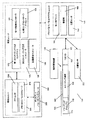
一実施形態においては、管腔内媒体内でのイメージングに適合性がある少なくとも1つのイメージング方式と、管腔内媒体の置換によってイメージング性能が向上する少なくとも1つのイメージング方式とを含む多方式イメージングシステムを提供する。図1は、多方式イメージングシステム100の例示的な実施形態を示すブロック図である。管腔内に挿入され、解剖構造102(例えば、管腔又は血管)に送達可能なイメージングプローブ105は、その先端115の近傍に設けられたイメージングアセンブリ110と、長手方向の実質的な一部に沿う任意のイメージング導管120と、基端部130に設けられたコネクタ125とを備える。
In one embodiment, a multi-modal imaging system comprising at least one imaging scheme that is compatible with imaging in an intraluminal medium and at least one imaging scheme that improves imaging performance by replacement of the intraluminal medium I will provide a. FIG. 1 is a block diagram illustrating an exemplary embodiment of a
イメージングアセンブリ110は、イメージングアセンブリ110の近くの領域をイメージングする際に、多方式信号(例えば、音響信号、光信号)を送信及び/又は受信するイメージングプローブ105の部品を包括的に指す。多方式イメージングアセンブリ110は、2つ以上のイメージング方式を用いるイメージングのための部品及びデバイスを含む。イメージングアセンブリ110は、イメージングトランスデューサ、検出器及び/又はイメージングエネルギ結合デバイス(imaging energy coupling devices)を備えていてもよい。所与のイメージング方式に基づいてプローブの付近で組織を照射するためのイメージングエネルギは、イメージングアセンブリ110内に収容されている1つ以上のトランスデューサが生成してもよく、及び/又はイメージングプローブの外部で1つ以上の外部のトランスデューサが生成し、エネルギ誘導デバイス(光ファイバ又は光導波路等)によって、イメージング導管120を介してイメージングアセンブリ110に送達してもよい。同様に、イメージングする組織内で生成又は散乱した所与のイメージング方式に関連する入射イメージングエネルギは、イメージングアセンブリ110内に収容されている検出器が受信してもよく、イメージングアセンブリ内で受信し、イメージング導管120内のイメージングエネルギ誘導デバイスを介して、外部検出器に供給してもよい。イメージングカプラ及び関連するエネルギ誘導デバイスが1つ以上のイメージング方式をサポートしてもよい。例えば、光ファイバ及びレンズ又はミラーアセンブリを使用して、OCTイメージング方式及びIRイメージング方式の両方に関連するイメージングエネルギを送達してもよい。2つ以上のイメージング方式に関連するイメージングエネルギは、共通のエネルギ生成及び/又は受信装置によって生成及び/又は受信してもよく、互いに周波数多重化及び/又は時間的にインタリーブしてもよい。イメージングプローブ105は、管腔内の径方向の視野を獲得するために、回転可能であってもよく、回転式イメージング要素を含んでいてもよい。
The
少なくとも1つのイメージング方式が光学イメージングである実施形態では、イメージングアセンブリ110は、通常、光ファイバの先端、及びレンズ(例えば、ボールレンズ又はGRINレンズとして知られる屈折率分布型レンズ)等の任意の光学部品の組合せを含み、これらは連携して、光受信機(イメージングされる組織から光エネルギを回収する回収要素)として機能し、光学エミッタ(出射された光ビームをイメージングされる組織に集光及び/又は方向付けする集光及び/又はビーム方向付け要素)としても機能できる。光学エミッタ及び/又は受信機の一部として、ミラー及び/又はプリズムが組み込まれることが多い。イメージングアセンブリ110、コネクタ125及び/又はイメージング導管120は、食塩水等の流体に浸すことができる。多方式の光学及び音響イメージングでは、イメージングプローブ105は、光学イメージングのために気体で満たされた少なくとも1つの区画又は管腔と、音響イメージングのために流体で満たされた少なくとも1つの区画又はチャンバとに区画分けされる。
In embodiments where the at least one imaging scheme is optical imaging, the
イメージング導管120は、通常、コネクタ125を介してエミッタ及び/又はレシーバをアダプタユニット140に接続する少なくとも1つの光導波路又は少なくとも1つ(オプションとして、2つ以上)の導線を含む。また、イメージング導管120は、イメージングアセンブリを回転又は平行移動するための機械的駆動力伝達メカニズムとして機能できる。例えば、イメージング導管120は、互いに絶縁された2層の電線によって包み込まれた光ファイバを含んでいてもよい。更に、イメージング導管120は、例えば、螺旋状に巻回されたワイヤ等の他の構造的特徴によって補強してもよく、又はスキャンメカニズムを回転させるイメージングトルクケーブルを構成するために用いられる当業者に周知の他の設計によって補強してもよい。また、イメージング導管は、イメージングプローブ105の先端に設けられ、イメージングアセンブリ110の1つ以上の部品を局所的に回転させるマイクロモータに電力を供給してもよい。
The
図3は、本発明の実施形態に基づく多方式イメージングシステムの部品として使うことができる多方式イメージングプローブの例示的な実施形態の斜視図である。図3に示すプローブは、2008年1月22日に出願された、米国特許出願番号第10/010,206号、発明の名称「Scanning Mechanisms for Imaging Probe」及び2009年3月27日に出願された、米国特許出願番号第12/385,014号、発明の名称「Scanning Mechanisms for Imaging Probe」に開示されているものであり、これらの内容の全体は、引用によって本願に援用される。簡潔に言えば、イメージングプローブは、イメージングアセンブリを含むことができ、イメージングアセンブリは、前方視方向に1つ以上の角度でイメージングエネルギビームを方向付ける可動部材を含む。2つの非制限的な具体例においては、可動部材の向きは、可動部材が旋回可能なイメージングアセンブリの回転速度を変更することによって、又は磁力若しくは駆動手段を用いて変更してもよい。 FIG. 3 is a perspective view of an exemplary embodiment of a multi-modal imaging probe that can be used as a component of a multi-modal imaging system in accordance with an embodiment of the present invention. The probe shown in FIG. 3 was filed on Jan. 22, 2008, US Patent Application No. 10 / 010,206, entitled “Scanning Mechanisms for Imaging Probe”, and Mar. 27, 2009. US patent application Ser. No. 12 / 385,014, entitled “Scanning Mechanisms for Imaging Probe”, the entire contents of which are incorporated herein by reference. Briefly, the imaging probe can include an imaging assembly that includes a movable member that directs the imaging energy beam at one or more angles in a forward viewing direction. In two non-limiting embodiments, the orientation of the movable member may be changed by changing the rotational speed of the imaging assembly about which the movable member can pivot, or using magnetic force or drive means.
例示的なイメージングプローブは、多方式イメージングのために、超音波方式(例えば、IVUS)及び光学方式(例えば、OCT)の両方を単一のカテーテルアセンブリに組み込んでいる。このシステムは、光ファイバ40と同軸電線50とを含むフレキシブルカテーテルを備える。基端部コネクタは、光ファイバ40を含み、光ファイバ40は、イメージング用の光ファイバ40を光イメージングシステム「バックエンド」に接続するアダプタに接続してもよい。更に、例えば、超音波処理システムのための電子回路又は電源回路及び/又はコントローラ及び処理ユニットに1つ以上の電気導管を接続するための電気的コネクタ56も設けられている。
Exemplary imaging probes incorporate both ultrasound (eg, IVUS) and optical (eg, OCT) into a single catheter assembly for multimodal imaging. The system includes a flexible catheter that includes an
この具体例におけるイメージング導管は、長軸を中心に回転し、回転する光ファイバプローブの接続は、イメージングプローブ10の基端部コネクタの一部として、又はアダプタ14の一部として組み込まれた光ファイバ回転継手を用いて実現されている。同様に、イメージング導管と共に回転する導線は、例えば、スリップリング又は回転トランスフォーマによって、相対的に固定されている超音波回路の導体及び/又はコントローラ及び処理ユニットに接続されている。これらのスリップリングは、イメージングプローブ10の基端部コネクタの一部として又はアダプタ14の一部として組み込むことができる。
The imaging conduit in this embodiment rotates about the long axis, and the connection of the rotating fiber optic probe is an optical fiber incorporated as part of the proximal connector of the
図3(a)は、図3のイメージングプローブの中央部の破線に沿った断面図であり、光ファイバ40、ガイドワイヤポート44及びガイドワイヤ42、イメージング導管34、イメージング導管管腔46、外側シース48、同軸電線50を示しており、外側シース48は、中空の柔軟な細長いシャフトであり、生体適合性を有する材料から形成され、この中空の細長いシャフトを体内の管腔及び空洞に挿入するために適する直径を有している。
FIG. 3A is a cross-sectional view taken along the broken line in the center of the imaging probe of FIG. 3, and shows an
イメージングプローブは、フラッシングを容易にするために、長手方向沿って1つ以上の箇所にポートを備えていてもよい。図3(b)に示すイメージングプローブ10の端部の拡大図は、外側シース48の端部において、外側シース48及びフラッシュポート54の端部を超えて延びるガイドワイヤ42の先端を示している。
The imaging probe may include ports at one or more locations along the longitudinal direction to facilitate flushing. The enlarged view of the end of the
図3に示すように、イメージングプローブ10の基端部は、ガイドワイヤ42が挿入されるガイドワイヤポート55と、コネクタアセンブリ36とを備え、コネクタアセンブリ36は、コネクタ本体に沿って、フラッシュポート58と電気コンタクト56とを備える。
As shown in FIG. 3, the proximal end of the
図3(c)は、アダプタによって、イメージングプローブの回転部品及び非回転部品をイメージングシステムの他の部分にどのように接続することができるかを概略的に示している。図3(d)は、イメージングプローブの回転する部品をアダプタの回転部品にどのように接続することができるかを図式的に示している。それぞれの回転部品は、当分野で周知のコネクタ及び他の構成を用いて、電気的、光学的及び/又は機械的に接続することができる。同様にイメージングプローブの非回転部品は、アダプタ14の非回転部品に接続することができる。アダプタ14は、スリップリング、回転トランスフォーマ、光学回転継手(optical rotary joints)、及び回転部品を非回転部品に電気的又は光学的に接続してシステムの他の部分との必要な電気信号及び光信号の通信を可能にするこれらに類する他の部材を含むことができる。
FIG. 3 (c) schematically shows how the rotating and non-rotating parts of the imaging probe can be connected to other parts of the imaging system by the adapter. FIG. 3 (d) schematically shows how the rotating part of the imaging probe can be connected to the rotating part of the adapter. Each rotating component can be electrically, optically and / or mechanically connected using connectors and other configurations well known in the art. Similarly, the non-rotating part of the imaging probe can be connected to the non-rotating part of the
二重光ファイバ回転継手(dual-fiber optical rotary joints)も使用できるが、構造がかなり複雑になる。イメージングプローブ12内の回転部品に装着されている如何なる導体間の電気的接続も、金属スリップリング及びスプリング、金属スリップリング及びブラシ又は静止した導体と回転する導体との間で導電コンタクトを形成するための他の周知の手法によって、非回転導電要素に接続することができる。 Dual-fiber optical rotary joints can also be used, but the structure is considerably more complicated. The electrical connection between any conductors mounted on a rotating component in the imaging probe 12 forms a conductive contact between a metal slip ring and spring, a metal slip ring and brush or a stationary conductor and a rotating conductor. It can be connected to the non-rotating conductive element by other known techniques.
図3(d)では、電気的、光学的及び機械的な接続を個別に示しているが、特定の実施形態の必要に応じて、幾つかのコネクタを結合コネクタに結合することによって、プローブとアダプタとの間を個別に接続する必要があるコネクタの数を減らして、幾つかのコネクタを削減し、より少ないコネクタで接続を行ってもよい。 In FIG. 3 (d), the electrical, optical and mechanical connections are shown separately, but depending on the needs of the particular embodiment, by connecting several connectors to the coupling connector, The number of connectors that need to be individually connected to the adapter may be reduced, some connectors may be reduced, and connections may be made with fewer connectors.
図4は、多方式イメージングアセンブリを組み込んだイメージングプローブの先端の内部構造の具体例を示している。アセンブリは、傾斜可能部品70を備え、傾斜可能部品70は、傾斜可能部品70に直接的に取り付けられていない1つ以上の部品によって出射及び/又は受信されるイメージングエネルギを偏向する。超音波トランスデューサ88及び光学エミッタ92は、イメージングエネルギを傾斜可能部品70に方向付ける。そして、イメージングエネルギは、傾斜可能部品70に取り付けられているエネルギ偏向部品によって偏向される。超音波イメージングのために、エネルギ偏向部品(傾斜可能部品70)は、例えば、固体金属表面(例えば、ステンレススチール)又は水晶等の結晶表面、ガラス又は硬質ポリマ等の音響反射面を備えていてもよい。
FIG. 4 shows a specific example of the internal structure of the tip of an imaging probe incorporating a multi-modal imaging assembly. The assembly includes a
光学イメージングのために、エネルギ偏向部品(傾斜可能部品70)は、例えば、研磨された金属から形成される鏡面、金属化二軸配向ポリエチレンテレフタレート(Mylar)等の金属化ポリマ、スパッタリング又は電気化学蒸着された金属、金属箔又は薄膜反射鏡等の他の反射性を有する部品等の光反射面を備えていてもよい。鏡面を形成するために一般的に使用される金属としては、アルミニウム、銀、鉄鋼、金又はクロム等が含まれる。 For optical imaging, the energy deflection component (tiltable component 70) can be, for example, a mirror surface formed from polished metal, a metallized polymer such as metallized biaxially oriented polyethylene terephthalate (Mylar), sputtering or electrochemical deposition. There may be provided a light reflecting surface such as a metal, metal foil or other reflective component such as a thin film reflecting mirror. Metals commonly used to form the mirror surface include aluminum, silver, steel, gold, or chromium.
図4(a)は、イメージングプローブ31の先端29の例示的な実施形態を示しており、ここでは、先端にイメージングアセンブリ30が設けられ、イメージングアセンブリ30は、傾斜可能部品70を含み、傾斜可能部品は、ピン72に取り付けられた円盤であり、円盤70は、ピンを中心に旋回可能である。
FIG. 4 (a) shows an exemplary embodiment of the
ピン72は、傾斜可能な円盤70の傾斜軸を画定する。イメージングアセンブリ30が静止しているとき、円盤70は、任意の開始位置に留まる。ここに示す具体例では、この開始位置は、最大のイメージング角度に対応する停止片80によって画定され、捻りバネ76によって付勢される回復力が円盤70を停止片80に押し付けている。図4(b)は、図4(a)の縦の破線2(c)−2(c)に沿った断面図である。
外部の力、例えば、重力、磁力、静電力、他の可動部品又は流体との摩擦力、圧縮力、てこの力、垂直抗力、又は傾斜軸を巡って傾斜可能部品70に加わる不完全な反対トルク(incompletely opposed torque)の他のソース等によって傾斜可能部品70が望ましい配向から傾くと、傾斜角が大きくなる。
External forces such as gravity, magnetic force, electrostatic force, frictional force with other moving parts or fluids, compressive force, leverage force, vertical drag, or imperfect opposition on the
1つ以上の停止片80、82によって、傾斜可能部品70の傾斜角の範囲を規制してもよい。例えば、停止片80は、傾斜可能部品70が停止片80に接触している状態で傾斜角のそれ以上の変更を妨げる停止片として、イメージングアセンブリ30のシェル84から延出するポスト(post)又はリップ(lip)であってもよい。したがって、停止片を用いて、停止片の位置によって画定される最大値を超えないように傾斜角を規制することができる。一旦、傾斜角がこの最大値に至ると、停止片80が傾斜可能部品70に加える垂直抗力が回復メカニズムに抗う。多くの実施形態において、この最大傾斜角は、イメージングアセンブリ30が静止し、低い回転速度である際に至る傾斜角である。
The range of the tilt angle of the
更なる又は代わりの停止片82を設け、傾斜可能部品70が動作範囲の上限の回転速度である際に至る最小傾斜角を画定してもよい。特定の実施形態についての以下の説明からも明らかであるが、実際には、傾斜角をゼロにすることによって特別な利益が得られないことも多い。
An additional or
イメージングアセンブリ30は、傾斜可能部品70の傾斜角を大きくすることに寄与する1つ以上のメカニズムを含むことできる。ここでは、説明のために、このようなメカニズムを回復メカニズム(restoring mechanism)と呼ぶ。回復メカニズムとしては、捻りバネ76(図4(a)及び図4(c))又は圧縮ばねを用いることができ、ここで、バネ76の一端は、傾斜可能部品70に機械的に接触又は接続されている。他端は、機械的にイメージングプローブ31の他の部分、例えば、イメージングアセンブリの本体に接続されている。
The
イメージングアセンブリ30が回転すると、円盤70は、円盤70の表面によって画定される面の法線が長軸に対して実質的に平行となるように、自らを整列させようとする。図4(c)に示すように、図示されている(最小のイメージング角度に対応する)他の停止片82は、イメージングアセンブリの高い回転速度において円盤70が望ましい配向に至ることを防ぐ。適切に構成されたイメージングアセンブリでは、最小のイメージング角度に対応する停止片82は、ゼロの角度に対応し、イメージングプローブの長軸に対して平行なイメージングを提供する。
As the
図5は、Courtney他によって2008年1月22日に出願された米国特許出願番号第12/010,208号、発明の名称「Imaging Probe with Combined Ultrasound and Optical Means of Imaging」に開示されている多方式イメージングシステムで使用される多方式イメージングアセンブリの他の具体例を示しており、この文献の全体は、引用によって本願に援用される。図5(a)に示すように、イメージングアセンブリ550は、音響及び光学手段による同じ方向におけるイメージングを実現するように構成され、音響トランスデューサ内のチャネルを介して光エネルギを伝達できるようにした音響トランスデューサを使用している。本質的には、アセンブリ550は、その基板を介して形成される光透過性チャネルを有するように変更された音響トランスデューサ502を使用する。音響トランスデューサ502は、当分野で周知の如何なる種類の超音波トランスデューサであってもよく、例えば、圧電体(例えば、PZT又はPVDF、圧電単結晶等)、複合トランスデューサ、又は容量型微細加工超音波トランスデューサ(capacitive micromachined ultrasonic transducer:cMUT)等であってもよい。
FIG. 5 shows a number of disclosures in US patent application Ser. No. 12 / 010,208 filed Jan. 22, 2008, entitled “Imaging Probe with Combined Ultrasound and Optical Means of Imaging” filed January 22, 2008 by Courtney et al. FIG. 2 shows another embodiment of a multi-modal imaging assembly for use in a modal imaging system, the entirety of which is incorporated herein by reference. As shown in FIG. 5 (a), the
導電体500は、トランスデューサの音響基板502の両側の導電層501に接続される。光ファイバ503は、光学イメージングを可能にするための光学導管を提供する。トランスデューサの出射面には、エポキシ層(例えば、銀又は銅導電性エポキシ層、これらは、トランスデューサを駆動する電極の一方又は両方として機能してもよい。)又はポリマ(例えば、パリレン又はPVDF)等の1つ以上の整合層を追加してもよい。
The
圧電材料502の両側の導電層501は、圧電体に電圧を印加する必要性から組み込まれる。開口507は、直接的に、又は1つ以上のミラー又はプリズム及び1つ以上のレンズ(図示せず)を介して、光導波路503に接続される。開口内に何らかの光学部品が含まれる場合、適応性がある材料、例えば、シリコン又はポリマ等の緩衝/絶縁層506によって、光学部品を音響基板502から分離することができ、これは、電気的絶縁体として機能し、又は音響基板502によって生じる圧力の光学部品への伝達を最小化する。
The
図5(b)に示すように、ファイバからの光は、ファイバからの光を光透過性チャネル507に偏向するミラー404(又はプリズム)に方向付けることができる。
As shown in FIG. 5 (b), the light from the fiber can be directed to a mirror 404 (or prism) that deflects the light from the fiber into a
更に、多方式イメージングシステムの他の非制限的な具体例は、Muller他によって出願された米国特許出願公開第2009/0299195号、発明の名称「Multimodal Catheter System and Method for Intravascular Analysis」のFigure1に示されており、この文献については、Figure1のみが引用によって本願に援用される。このシステムは、単一の脈管内処置によって、動脈形態における複数の異なる異常を検出するために、血管内超音波法、光干渉断層法、近赤外線分光法を組み合わせている。 Further, other non-limiting examples of multi-modal imaging systems are shown in FIG. 1 of US Patent Application Publication No. 2009/0299195, filed by Muller et al., Entitled “Multimodal Catheter System and Method for Intravascular Analysis”. For this document, only FIG. 1 is incorporated herein by reference. This system combines intravascular ultrasound, optical coherence tomography, and near infrared spectroscopy to detect multiple different abnormalities in arterial morphology with a single intravascular procedure.
上述の具体例は、後述する本発明の実施形態に適用することができる多方式イメージングシステムを例示している。なお、上述の具体例は、非制限的な具体例として提示したものであり、本発明の実施形態では、他の多方式イメージングプローブを用いることもできる。 The specific examples described above illustrate a multi-modal imaging system that can be applied to embodiments of the present invention described below. The above specific examples are presented as non-limiting specific examples, and other multi-system imaging probes can be used in the embodiments of the present invention.
再び図1を参照して説明すると、多方式イメージングシステム100は、非侵襲的処置の間に管腔内媒体を置換し、イメージングの間に管腔内媒体を移動させることが有利なイメージング方式をサポートするように構成されている。このような置換は、以下に限定されるものではないが、米国特許出願公開番号第2009/0299195号、及び全体が引用により本願に援用される米国特許番号第7,758,499号、発明の名称「Method and Apparatus for Viewing Through Blood」に開示されているような、管腔内フラッシングによる管腔内媒体の置換のためのサブシステム及び管腔の制御された遮断による管腔内媒体の置換のためのサブシステムを含む多くのデバイス及びサブシステムの1つによって提供及び制御してもよい。
Referring again to FIG. 1, the
一実施形態においては、管腔内フラッシングは、入力ポートを介してイメージングプローブ105にフラッシュ液を供給し、イメージングプローブの長手方向の1つ以上の箇所に設けられている出力ポートからフラッシュ液を管腔に流し込むことによって達成される。これに代えて、フラッシュ液は、イメージングされる管腔に流体を導入できる従来のガイドカテーテルを介して供給してもよい。これに代えて、フラッシュ液は、例えば、全体が引用により本願に援用される米国特許番号第7,625,366号、発明の名称「Flush Catheter with Flow Directing Sheath」に開示されているような専用のフラッシュカテーテルを介して供給してもよい。フラッシュ液、例えば食塩水、乳酸リンゲル液又は造影剤は、手動で、例えば、外部の注射器を用いて供給してもよい。幾つかの例示的な実施形態では、フラッシュは、自動注入器、圧力注入バッグ、蠕動ポンプ、シリンジポンプ又はピストンポンプ、バルブシステム、重力加圧システム、自動又は手動の圧力印加を用いた外部からの媒体への加圧によって行ってもよい。
In one embodiment, the intraluminal flushing supplies flush fluid to the
一実施形態においては、符号135で包括的に示す媒体置換装置は、1つ以上の媒体置換動作を提供及び/又は調整又は制御する。上述のように、媒体置換装置135は、インタフェースを介してイメージングプローブ105に接続してもよく、媒体置換を行うための又は独立した装置(例えば、ガイドカテーテル又は専用のフラッシュカテーテル)として設けてもよい。非制限的な具体例では、媒体置換装置135は、(タンクから)関心領域へのフラッシュ液の量を制御する外部ポンプ(図示せず)を含んでいてもよい。他の具体例では、媒体置換装置135は、イメージングプローブ110上又はイメージングプローブ110内に収容され、制御された膨張によって管腔を完全に又は部分的に閉塞し、媒体置換を達成する膨張可能なバルーンを備えていてもよい。
In one embodiment, the media replacement device, indicated generally at 135, provides and / or regulates or controls one or more media replacement operations. As described above, the
他の実施形態においては、媒体置換装置135は、更に、ユーザ又は医師がスイッチを操作したときのみ自動化された置換動作を実行又は許可する外部の手動スイッチを含んでいてもよい。このようなスイッチは、何らかの自動化された置換動作を監視する際に、人間の施術者が能動的に関与することを要求する半自動化された媒体置換の管理モードを実現する。適切なスイッチの非制限的な具体例は、自動化された置換(例えば、注入又は膨張)を実行するために、継続的に押下する必要があるボタン又はフットペダルを含む。
In other embodiments, the
再び図1を参照して説明すると、ドライバ及びアダプタユニット140は、イメージングプローブ105と、適切な制御及び/又は処理サブシステムとの間で、何らかのファイバ及び/又はワイヤによる動力及び/又は信号の伝達を可能にするインタフェースを備える。これはイメージングプローブの回転部品に回転動作を伝えるモータドライバサブシステム145を含むことができる。また、モータドライバは、後退メカニズム、前進メカニズム又は前後往復メカニズムを作動して、イメージングアセンブリ110の長手方向の平行移動を行ってもよい。このようなイメージングアセンブリ110のこのような長手方向の平行移動は、イメージアセンブリ110及びイメージング導管120を包囲する外部シャフト(図示せず)の長手方向の平行移動を伴って実行してもよく、相対的に静止している外部シャフト内で実行してもよい。
Referring again to FIG. 1, the driver and
ドライバ及びアダプタユニット140の部品として、更なるセンササブシステム、例えば、イメージングプローブ110内の回転部品の回転角及び/又はイメージングアセンブリ110の長手方向の位置を感知する位置感知サブシステム150を組み込んでもよい。また、イメージングプローブ110は、イメージングプローブ110に関連する情報、例えば、イメージングプローブ110の仕様を特定する情報及び/又は較正情報を格納するメモリ部品、例えば、EEPROM又は他のプログラマブルメモリデバイスを備えていてもよい。更に、ドライバ及びアダプタユニット140は、イメージングプローブ110とシステムの他の部分との間の電気信号又はパワーの伝達を向上させる増幅器160を備えていてもよい。
As a component of the driver and
ドライバ及びアダプタユニット140は、インタフェースを介して制御ユニット165に接続されている。制御ユニット165は、多方式イメージングデバイスをサポートする第1のイメージング方式コントローラサブシステム170及び第2のイメージング方式コントローラサブシステム175(システムは、ここに示す2つに加えて、更なるイメージング方式及びコントローラを含むことができる。)を備え、多方式イメージングには、以下に限定されるものではないが、(1)超音波、(2)光干渉断層法、(3)血管内視鏡、(4)赤外線イメージング(5)近赤外線イメージング、(6)Raman分光法ベースのイメージング及び(7)蛍光イメージング等のイメージング方式の何れが含まれていてもよい。
The driver and
ここでは、第1及び第2のイメージング方式コントローラを個別のサブシステムとして示しているが、これらは、1つであってもよく、同じであってもよい。例えば、OCTデータ及び近赤外線(NIR)分光データは、共通の光源及び信号取得システムを介して取得することができる。また、第1及び第2の方式が共にIVUSであり、一方の方式が他方の方式より低い周波数のIVUSである場合、IVUSデータの2つのセットを生成及び取得するために要求されるハードウェアは、動作パラメータが異なるだけで、同じであってもよい。 Here, although the first and second imaging scheme controllers are shown as separate subsystems, these may be one or the same. For example, OCT data and near infrared (NIR) spectroscopic data can be acquired through a common light source and signal acquisition system. Also, if both the first and second schemes are IVUS and one scheme is a lower frequency IVUS than the other scheme, the hardware required to generate and obtain two sets of IVUS data is The operating parameters may be the same but only different.
光学方式コントローラは、干渉計部品、1つ以上の光学基準アーム、光学マルチプレクサ、光学デマルチプレクサ、光源、光検出器、分光器、偏光フィルタ、偏光コントローラ、タイミング回路、アナログ/デジタル変換器及びここに開示し又は引用によって援用される何らかの光学イメージング技術を補助する周知の他の部品等の部品の何れか又は全てを含むことができる。 Optical controller includes interferometer component, one or more optical reference arms, optical multiplexer, optical demultiplexer, light source, photodetector, spectrometer, polarization filter, polarization controller, timing circuit, analog / digital converter and Any or all of the components may be included, such as other well-known components that assist in any optical imaging technique disclosed or incorporated by reference.
超音波方式コントローラは、パルス発生器、電子フィルタ、アナログ/デジタル変換器、並列処理アレイ、エンベロープ検出器、時間利得補償増幅器を含む増幅器及びここに開示し又は引用によって援用される何らかの音響イメージング技術を補助する周知の他の部品等の部品の何れか又は全てを含むことができる。制御ユニット165は、以下に限定されるものではないが、モータ駆動コントローラ180、位置感知制御回路190、タイミング回路、立体イメージング(volumetric imaging)プロセッサ、走査変換器及びこの他のサブシステムの1つ以上を含むことができる。
An ultrasonic controller includes a pulse generator, an electronic filter, an analog / digital converter, a parallel processing array, an envelope detector, an amplifier including a time gain compensation amplifier, and any acoustic imaging technology disclosed or incorporated herein by reference. Any or all of the parts, such as other well-known auxiliary parts, can be included. The
図1に示すように、媒体置換装置135は、制御ユニット165から独立して操作及び/又は制御できる。例えば、媒体置換装置135は、注射器又は手動ポンプを含んでいてもよい。図2に示す他の実施形態においては、制御ユニット165は、媒体置換動作を監視し、媒体置換動作を自動化又は半自動化することもできる媒体置換コントローラ185を更に備える。他の実施形態では、媒体置換コントローラ185は、インタフェースを介して媒体置換装置135に直接的に接続してもよい。媒体置換コントローラ185は、以下に限定されるものではないが、所与の媒体置換動作に供給されるフラッシュ液の体積、所与の患者及び/又は低侵襲処置のための複数の媒体置換動作に供給されるフラッシュ液の総量、所与の媒体置換動作が行われる継続時間、所与の患者及び/又は低侵襲処置のための複数の媒体置換動作が行われる継続時間の合計、媒体置換を行うためにデバイス又はサブシステムに伝達される制御信号及び/又はコマンド等を含む情報を監視できる。
As shown in FIG. 1, the
媒体置換コントローラ185は、後に更に説明するように、処理ユニット205によって調整される一連のイメージング及び置換動作の制御の間に使用されるフィードバックループへの入力を提供してもよい。
The
制御ユニット165は、更に、オプションの心臓センサ200、例えば、イメージングされる患者の体から心電図信号を取得する電極センサを制御するオプションの心臓センサコントローラ195を含むことできる。心電図信号は、心運動が画質に影響を与える状況下で、イメージングデータの取得のタイミングを計るために使用することができる。また、心電図は、取得シーケンスを開始する際の、例えば、所望のスキャンパターンを実現するために、モータの回転速度を変更する際のトリガとしても機能できる。例えば、イメージングシーケンスを心電図(electrocardiogram:ECG)によってトリガすることによって、収縮期又は拡張期等の心周期の特定のフェーズの間に画像を取得することができる。心電図信号は、オプションとして、観測された生理的な状態下で、システムが拍動性又は血流を考慮して媒体置換システムの注入レート又は膨張レートを変更するトリガと機能してもよい。
The
制御ユニット165は、インタフェースを介して処理ユニット205に接続され、処理ユニット205は、バスによって接続されたプロセッサ210とメモリ及び/又はストレージサブシステム215を備え、システム動作の様々な側面を調整するための複数の処理機能を実行する。なお、制御ユニット165及び処理ユニット205は、個別のサブシステムとして示しているが、これらは、統合されたコンピュータシステム220内に設けてもよい。更に、制御ユニット165の要素の幾つか又は全てを処理ユニット205が実行してもよい。更に、プロセッサ210は、1個以上のCPU、フィールドプログラマブルゲートアレイ、GPU、ASIC、DSPチップ及び当分野で周知の他の処理要素等の複数の処理要素を含んでいてもよい。また、処理ユニット205は、実時間表示又はイメージングデータの取得時より後のデータの表示のためにディスプレイ及びユーザインタフェース225に接続してもよい。
The
更に、イメージングシステム100は、データストレージコンポーネント(例えば、メモリ、ハードディスクドライブ、リムーバブルストレージデバイス、CDやDVD等の携帯ストレージ媒体のためのリーダ及びレコーダ)を備えていてもよく、これらは、インタフェースを介して、処理ユニット及び/又は制御ユニットの部品に接続してもよい。
In addition, the
一実施形態においては、処理ユニット205は、第1のイメージング方式を用いて取得された画像を解析し、イメージング結果を利用して、画像取得の間に管腔内媒体置換動作を要求し又はこれが有利である第2のイメージング方式に基づく画像の記録を自動化するようにプログラムされる。第1のイメージング方式は、管腔内媒体に適合性を有していてもよく、すなわち、十分な診断感度又は臨床的有用性を有する画像を取得するために管腔内置換動作を必要としなくてもよい。
In one embodiment, the
管腔内液体が血液である一実施形態では、第1のイメージング/検出方式は、以下に限定されるものではないが、グレースケールIVUS、無線周波数IVUS(例えば、Virtual Histology(商標)、統合後方散乱(integrated backscatter)又はiMap(商標))、エラストグラフィ、NIR分光法、ソノルミネッセントイメージング(sono-luminescent imaging)、マイクロバブル増強IVUS(microbubble enhanced IVUS)、標的マイクロバブル増強IVUS(targeted microbubble enhanced IVUS)、光音響イメージング、蛍光分光法、イオン選択電界効果トランジスタ等のバイオセンサの何れかであってもよく、第2のイメージング方式は、以下に限定されるものではないが、OCT、血管内視鏡、NIR分光法、Raman分光法、IVUS、無線周波数IVUS、エラストグラフィ、ソノルミネッセントイメージング、マイクロバブル増強IVUS、標的マイクロバブル増強IVUS、蛍光分光法、光音響イメージングの何れかであってもよい。生来的に光学的な方式である第2のイメージング方式は、電磁波スペクトルにおける紫外線、可視光線、NIR及び/又は赤外線の部分の波長を使用してもよい。 In one embodiment, where the intraluminal fluid is blood, the first imaging / detection scheme is not limited to the following: grayscale IVUS, radio frequency IVUS (eg, Virtual Histology ™, integrated posterior Integrated backscatter or iMap ™, elastography, NIR spectroscopy, sono-luminescent imaging, microbubble enhanced IVUS, targeted microbubble enhanced IVUS IVUS), photoacoustic imaging, fluorescence spectroscopy, ion-selective field effect transistors, or other biosensors. The second imaging method is not limited to the following, but is not limited to OCT, intravascular Endoscope, NIR spectroscopy, Raman spectroscopy, IVUS, Line frequency IVUS, elastography, sono-luminescent imaging, microbubbles enhance IVUS, targeted microbubbles enhance IVUS, fluorescence spectroscopy, may be any of photoacoustic imaging. The second imaging scheme, which is inherently an optical scheme, may use the wavelengths of the ultraviolet, visible, NIR and / or infrared portions of the electromagnetic spectrum.
他の実施形態においては、第1及び第2のイメージング方式は、単一のイメージング方式であってもよく、この場合、まず、管腔内媒体がある状態で画像を取得し、次に、置換処理によって向上された画像を取得してもよい。 In other embodiments, the first and second imaging schemes may be a single imaging scheme, in which case an image is first acquired in the presence of an intraluminal medium and then replaced. You may acquire the image improved by the process.
超音波は、血液に対する妥当な侵入性を有しているが、超音波イメージングプローブの視野から血液を置換することによって、血管壁を特定する能力を更に向上させることができ又は画像コントラストを向上させることができる。一方、超音波は、例えば、血液及び軟組織等の生物学的媒体に良好に侵入する能力を有し、光干渉断層法の侵入深度を超える数ミリメートル又は数センチメートルの幅の侵入深度を有する。 Ultrasound has reasonable penetration into blood, but by replacing blood from the field of view of the ultrasound imaging probe, the ability to identify vessel walls can be further improved or image contrast can be improved. be able to. Ultrasound, on the other hand, has the ability to penetrate well into biological media such as blood and soft tissue and has a penetration depth of a few millimeters or a few centimeters beyond the penetration depth of optical coherence tomography.
一実施形態においては、第1及び第2のイメージング方式は、何れもIVUSであり、第1の方式は、第2のIVUS方式より低い周波数範囲を有するIVUSである。一般化して言えば、超音波の周波数がより高いと、低い周波数より解像度が高くなるが、周波数を高くすると、血液への侵入が浅くなる。したがって、より高い周波数のIVUSでイメージングを行う場合、血液を置換することが望ましい。2つのIVUSイメージング周波数について、個別の超音波トランスデューサを設けてもよく、1つの超音波トランスデューサが2つ以上のイメージング周波数をサポートできる十分広い帯域幅を有していてもよく、ここでイメージング周波数は、超音波トランスデューサを励起するパルス発生器(pulser)によって使用されるパルスの周波数によって部分的に決定される。 In one embodiment, the first and second imaging schemes are both IVUS, and the first scheme is an IVUS having a lower frequency range than the second IVUS scheme. Generally speaking, the higher the ultrasonic frequency, the higher the resolution than the lower frequency, but the higher the frequency, the shallower the penetration into the blood. Therefore, it is desirable to replace blood when imaging with higher frequency IVUS. Separate ultrasound transducers may be provided for the two IVUS imaging frequencies, and one ultrasound transducer may have a sufficiently wide bandwidth to support more than one imaging frequency, where the imaging frequency is , Partly determined by the frequency of the pulses used by the pulser that excites the ultrasonic transducer.
単一のイメージングプローブを用いて、超音波と、例えば、OCT又は近赤外線分光法等の光学イメージング法とを組み合わせる能力は、必要な解像度及び侵入深度の選択に関して有利である。更に、光干渉断層法によって取得される情報の多くは、超音波によって取得される情報を補足し、両方のイメージング法によって取得された情報を解析又は表示することによって、検査される組織への理解、例えば、その組成に関する理解を深める能力が向上する。 The ability to combine ultrasound and optical imaging methods such as, for example, OCT or near infrared spectroscopy, using a single imaging probe is advantageous with respect to the required resolution and penetration depth selection. In addition, much of the information acquired by optical coherence tomography supplements the information acquired by ultrasound and understands the tissue being examined by analyzing or displaying the information acquired by both imaging methods. For example, the ability to deepen understanding about the composition is improved.
なお、脈管内OCTは、血液の存在によって深刻に妨害されるが、NIR分光法は、それほど影響を受けず、血液を介して数ミリメートルの深さまでプラーク組成を評価できる。しかしながら、これは、より大きな血管、及び動脈瘤がなければ内径が通常である筈の血管における動脈瘤の部分に対しては効果的ではない。 Although intravascular OCT is severely disturbed by the presence of blood, NIR spectroscopy is not significantly affected and can evaluate plaque composition to a depth of a few millimeters through the blood. However, this is not effective for larger blood vessels and parts of the aneurysm in the hemorrhoidal blood vessels that normally have an inside diameter without an aneurysm.
図6は、置換可能な管腔内媒体の存在によって妨害される第2のイメージング方式によって次に画像を取得する際に、第1のイメージング方式を用いて記録された画像を用いて置換動作を行う実施形態を示すフローチャートである。 FIG. 6 illustrates the replacement operation using the image recorded using the first imaging scheme when the next image is acquired by the second imaging scheme that is hindered by the presence of the replaceable intraluminal medium. It is a flowchart which shows embodiment to perform.
ステップ300において、置換可能な管腔内媒体の存在に適合性がある第1のイメージング方式によって画像を取得するために、多方式イメージングプローブ、例えば、図1のイメージングプローブ105を管腔に挿入する。第1のイメージング動作は、例えば、後退等の平行移動動作であってもよく、これは、第1のイメージング方式を用いてイメージングデータを記録しながら実行される。平行移動動作は、自動化してもよく、第1のイメージング方式のために選択及び/又は最適化された一定の平行移動速度で実行してもよい。第1の平行移動動作の間に第1のイメージング方式デバイス(イメージングプローブ105のイメージングアセンブリ110内に設けられている。)から得られた信号は、第1のイメージング方式コントローラ170に供給される。
In
この実施形態では、平行移動動作の間に位置感知を採用し、基準位置に対する及びオプションとして基準方向に対する記録された画像の位置を特定する。したがって、記録された画像は、イメージングプローブの位置及びオプションとして向きと関連付けられる。位置感知は、周知の手法の1つを用いて行ってもよく、図1では、包括的に、位置センサ150及び位置感知コントローラ190(これらは、共に複合サブシステムを形成してもよい)として示している。
In this embodiment, position sensing is employed during the translation operation to locate the recorded image relative to the reference position and optionally relative to the reference direction. Thus, the recorded image is associated with the position and optionally the orientation of the imaging probe. Position sensing may be performed using one of the well-known techniques, and in FIG. 1, as a comprehensive,
一実施形態においては、位置感知は、例えば、イメージングプローブ、後退モータ又は駆動素子に接続されたエンコーダ又は他の位置センサを用いた管腔内の長手方向の位置感知によって行われる。位置感知は、空間領域測定によって行ってもよく、平行移動又は回転運動が既知の速度で行われている場合、時間領域測定に基づいて推定してもよい。例えば、イメージングプローブの長手方向の位置に関する位置情報は、平行移動が行われた期間に基づいて推定でき、これは、この期間におけるイメージングプローブの位置の変化率が既知であることを前提としている。プローブの平行移動の間、位置の変化率は、一定であってもよい。回転角感知は、引用により全体が本願に援用される、2008年1月22日に出願された同時に係属中の米国特許出願番号第12/010,207号、発明の名称「Medical Imaging Probe with Rotary Encoder」に開示されているように、イメージングプローブに接続された回転エンコーダ又は他の位置センサを用いて行うことができる。 In one embodiment, position sensing is performed by longitudinal position sensing in the lumen, for example using an imaging probe, a retract motor or an encoder or other position sensor connected to a drive element. Position sensing may be performed by spatial domain measurements and may be estimated based on time domain measurements if translation or rotational motion is performed at a known speed. For example, the position information related to the position in the longitudinal direction of the imaging probe can be estimated based on the period during which the translation is performed, which is based on the premise that the rate of change of the position of the imaging probe during this period is known. During the translation of the probe, the rate of change of position may be constant. Rotational angle sensing is described in co-pending US patent application Ser. No. 12 / 010,207, filed Jan. 22, 2008, incorporated herein by reference in its entirety, and entitled “Medical Imaging Probe with Rotary. This can be done using a rotary encoder or other position sensor connected to the imaging probe, as disclosed in Encoder.
他の実施形態においては、位置感知は、イメージングプローブ内に設けられ、外部的に生成されたフィールド、例えば、磁界内でイメージングプローブの位置を判定する検出要素を用いて行ってもよく、これは、向き検出と組み合わせて実行してもよい。Muller他による米国特許出願公開番号第2009/0299195号に開示されているように、メディガイドリミテッド社(Mediguide Ltd.)が提供している適切なセンサを採用してもよい。 In other embodiments, position sensing may be performed using a sensing element that is provided within the imaging probe and that determines the position of the imaging probe within an externally generated field, eg, a magnetic field, , Or in combination with orientation detection. A suitable sensor provided by Mediguide Ltd. may be employed, as disclosed in US Patent Application Publication No. 2009/0299195 by Muller et al.
第1の平行移動動作を実行した後に、ステップ305において、画像解析のために、第1のイメージング方式コントローラ170からの画像データをプロセッサ210に供給する。プロセッサ210は、画像処理アルゴリズムに基づいて画像データを解析して、関心領域、例えば、診断、研究及び/又は臨床的な関心の対象となる領域を特定する。特定される領域は、様々な解剖学的構造及び/又は特徴を表すことができ、これらは、以下に限定されるものではないが、後の解析のための所望の組織タイプ、特定の解剖学的特徴、既知の又は疑いのある病理上の構造又は特徴、及び医療用又は他の人工的構造を含む。適切な関心領域は、以下に限定されるものではないが、プラーク、可能性がある血栓、分岐点(branch points)、病巣、石灰化領域、ステント又は近接照射療法インプラント等の移植領域、狭窄部、血管壁の肥厚領域、脂質コア、壊死領域、線維性被膜、解離部(dissections)、腫瘤(masses)等がある。関心領域は、更に、検出されたマイクロバブル、例えば、標的マイクロバブル(targeted microbubbles)を含む領域であってもよい。また、関心領域は、更なるイメージングデータがなければ自動化又は半自動化された処理アルゴリズムが関心領域を確定的に評価できない不確定(indeterminate)又は不確実(uncertain)な構造又は組成を含んでいてもよい。
After performing the first translation operation, in
関心領域は、更に、臨床症状に至っていないが、破裂又は浸食のリスクが高く、急性心筋梗塞を引き起こす可能性がある血管病巣を含んでいてもよい。これらの所謂「不安定プラーク(vulnerable plaques)」は、これらのプラークを治療して不利な臨床的事象を予防することが概念的に望ましいために関心領域となる。 The region of interest may further include vascular lesions that have not resulted in clinical symptoms but are at high risk of rupture or erosion and can cause acute myocardial infarction. These so-called “vulnerable plaques” are areas of interest because it is conceptually desirable to treat these plaques to prevent adverse clinical events.
他の実施形態においては、第1のイメージング方式に基づいて得られた何らかの画像から、不確定な結果が疑われる如何なる領域も関心領域として特定できる。例えば、第1のイメージング方式としてNIR分光法を使用する場合、イメージングプローブのイメージングアセンブリから血管壁までの距離が、血液の存在下でのNIR分光法プローブの範囲によって許容されている距離より更に遠い領域を関心領域として定義してもよい。これに代えて、IVUSイメージングの場合、このような領域は、血管壁がイメージングプローブに接触している領域として定義してもよい。IVUSでは、カテーテルに最も近い視野の一部で幾らかのアーチファクトが生じることがある。これらは、トランスデューサリングダウン(transducer ring-down)と呼ばれる現象及びカテーテルのシースから生じる超音波反射に起因するアーチファクトを含む。OCTは、このようなアーチファクトによる影響を実質的に受けず、カテーテルに最も近い視野の部分でも良好な画像が得られる。 In other embodiments, any region in which an indeterminate result is suspected can be identified as a region of interest from any image obtained based on the first imaging scheme. For example, when using NIR spectroscopy as the first imaging scheme, the distance from the imaging assembly of the imaging probe to the vessel wall is further than the distance allowed by the range of the NIR spectroscopy probe in the presence of blood. A region may be defined as a region of interest. Alternatively, in the case of IVUS imaging, such a region may be defined as a region where the blood vessel wall is in contact with the imaging probe. In IVUS, some artifacts may occur in the part of the field of view closest to the catheter. These include a phenomenon called transducer ring-down and artifacts due to ultrasonic reflections arising from the sheath of the catheter. OCT is substantially unaffected by such artifacts, and a good image can be obtained even in the portion of the visual field closest to the catheter.
一実施形態においては、関心領域は、既知の幾何学的形状、構造的形態及び/又はイメージング信号の特性を有するステントを含むことができる。これは、金属ステント、ポリマステント、生分解性ステント、ペースメーカワイヤ、ガイドワイヤ等を含んでいてもよい。 In one embodiment, the region of interest may include a stent having a known geometric shape, structural morphology, and / or imaging signal characteristics. This may include metal stents, polymer stents, biodegradable stents, pacemaker wires, guide wires and the like.
関心領域は、多くの既知の画像解析法の1つを用いて特定できる。関心領域は、処理画像によって、予想される値又は範囲と比較することができるメトリック(metrics)を算出することによって特定してもよい。他の具体例では、画像解析は、関心領域を特定するためのパターン認識法と組み合わせて実行される。一具体例においては、イメージング解析は、境界検出を含む。例えば、境界検出を用いて、プラーク肥厚が生じている領域を検出してもよく、この領域は、第2のイメージング方式による後のイメージングに適合する。境界検出は、多くの異なる手法で実施できる。1つの非制限的な具体例として、Papadogiorgaki他は、輪郭最適化技術を用いた境界検出を開示している(Ultrasound in Medicine and Biology 2008, Sept 34(9) 1482-98)。また、境界検出の方法は、例えば、米国特許番号第7,359,554号、発明の名称「System and Method for Identifying a Vascular Border」及び米国特許出願公開番号第2005/0249391号、発明の名称「Method for Segmentation of IVUS Image Sequences」にも開示されており、これらは何れも引用によって全体が本願に援用される。 The region of interest can be identified using one of many known image analysis methods. The region of interest may be identified by calculating metrics that can be compared with expected values or ranges by the processed image. In another embodiment, the image analysis is performed in combination with a pattern recognition method for identifying a region of interest. In one embodiment, the imaging analysis includes boundary detection. For example, boundary detection may be used to detect an area where plaque thickening has occurred, and this area is compatible with subsequent imaging by the second imaging scheme. Boundary detection can be implemented in many different ways. As one non-limiting example, Papadogorgaki et al. Discloses boundary detection using contour optimization techniques (Ultrasound in Medicine and Biology 2008, Sept 34 (9) 1482-98). In addition, the boundary detection method includes, for example, US Pat. No. 7,359,554, the name of the invention “System and Method for Identifying a Vascular Border” and US Patent Application Publication No. 2005/0249391, the name of the invention “ "Method for Segmentation of IVUS Image Sequences", both of which are incorporated herein by reference in their entirety.
一実施形態においては、関心領域は、組織特性評価技術を含む画像処理法によって特定される。例えば、引用により全体が本願に援用されるNairによる米国特許番号第6,200,268号に開示されているように、第1のイメージング方式がIVUS又はそのバリエーションである実施形態では、関心領域は、パターン認識アルゴリズムと組み合わせて、後方散乱超音波信号の無線周波数特性によって判定してもよい。これに代えて組織特性評価技術は、グレースケール画素の輝度解析を採用してもよい。例えば、生成された画像において、ある輝度範囲の画素は、軟性プラーク(soft plaque)を表している可能性が高く、これは、更に、脂質過多領域(lipid-rich regions)を含んでいる可能性がある。これに代えて、組織解析アルゴリズム例えば、ウェーブレット分解アルゴリズム又はイメージングデータの統計的特性を評価するアルゴリズムを用いてもよい。これに代えて、ある組織成分の既知の特性を検出する発見的アルゴリズムを用いてもよい。例えば、アルゴリズムは、IVUSイメージングにおいて石灰化の存在との相関性が高いことが知られている音響陰影を検出してもよい。 In one embodiment, the region of interest is identified by an image processing method that includes tissue characterization techniques. For example, in embodiments where the first imaging scheme is IVUS or a variation thereof, as disclosed in US Pat. No. 6,200,268 by Nair, which is hereby incorporated by reference in its entirety, the region of interest is In combination with the pattern recognition algorithm, the determination may be made based on the radio frequency characteristics of the backscattered ultrasonic signal. Alternatively, the tissue characteristic evaluation technique may employ luminance analysis of gray scale pixels. For example, in the generated image, a pixel in a certain luminance range is likely to represent soft plaque, which may further include lipid-rich regions. There is. Alternatively, a tissue analysis algorithm such as a wavelet decomposition algorithm or an algorithm for evaluating statistical characteristics of imaging data may be used. Alternatively, a heuristic algorithm that detects a known characteristic of a tissue component may be used. For example, the algorithm may detect acoustic shadows that are known to be highly correlated with the presence of calcification in IVUS imaging.
特定の領域について最も可能性が高い組織組成を特定することができるパターン認識アルゴリズムに幾つかのイメージングデータパラメータを入力することが望ましい場合がある。このようなパターン認識アルゴリズムは、ニューラルネットワーク、ファジィ論理アルゴリズム、データ分類木、最近近接法、他の幾つかのパターン認識法であってもよい。このようなパターン認識アルゴリズムは、組織学、X線撮影、分光法、超音波、光学イメージング及びこの他の何らかの組合せによって、組織の実際の基本的な組成が既知であるイメージングデータを用いてトレーニングしてもよい。このようなパターン認識アルゴリズムは、所与の関心領域について、可能性が高い組織の基本的な組成を特定するだけではなく、正しさの尤度の推定をも提供する。これに代えて、パターン認識アルゴリズムは、単に、第1のイメージング方式によっては、基本的な組成が不確実である領域を特定し、第2のイメージング方式による更なる解析の必要性を促すものであってもよい。 It may be desirable to enter some imaging data parameters into a pattern recognition algorithm that can identify the most likely tissue composition for a particular region. Such a pattern recognition algorithm may be a neural network, a fuzzy logic algorithm, a data classification tree, a nearest neighbor method, or some other pattern recognition method. Such pattern recognition algorithms are trained using histology, radiography, spectroscopy, ultrasound, optical imaging and some other combination using imaging data where the actual basic composition of the tissue is known. May be. Such pattern recognition algorithms not only identify the basic composition of likely tissue for a given region of interest, but also provide an estimate of the likelihood of correctness. Instead, the pattern recognition algorithm simply identifies areas where the basic composition is uncertain, depending on the first imaging method, and encourages the need for further analysis by the second imaging method. There may be.
これに加えて、又はこれに代えて、関心領域は、非イメージング方式に基づいて、例えば、温度不均一性に基づいて判定してもよい。温度不均一性を検出する方法の具体例は、例えば、「Stefanidis C, et al., "Thermal heterogeneity within human atherosclerotic coronary arteries detected in vivo: a new method of detection by application of a special thermography catheter", Circulation 1999;99;1965-71」に開示されている。プローブ115の先端部分に温度センサを組み込んで、動脈壁の温度の変化を検出してもよく、温度がより高い領域は、炎症領域に対応している可能性が高いと考えられる。更に他の実施形態では、関心領域は、選択的な検出分子種、例えば、抗体又はアプタマが結合されたイオン選択性電界効果トランジスタ(ion-selective field effect transistor:ISFET)等の局所的バイオセンサによって局所的に検出された生物学的検体、例えば、C反応性蛋白(C-reactive protein:CRP)を検出する炎症のマーカの濃度が最小の領域に基づいて判定してもよい。
In addition or alternatively, the region of interest may be determined based on a non-imaging scheme, for example, based on temperature non-uniformity. Specific examples of methods for detecting temperature heterogeneity include, for example, `` Stefanidis C, et al., `` Thermal heterogeneity within human atherosclerotic coronary arteries detected in vivo: a new method of detection by application of a special thermography catheter '', Circulation 1999; 99; 1965-71 ”. A temperature sensor may be incorporated in the distal end portion of the
上述したような第2のイメージング方式による更なる解析のために関心領域を特定するために自動化されたシステム及び方法は、関心領域の識別に影響を与えるパラメータをユーザが調整又は変更できる設定を含むことができる。例えば、このような設定によって、ユーザは、特定の病理上の特徴又は構造を選択することができ、例えば、少なくとも選択された量のプラーク、選択された最小の血管壁厚、又は選択された壁厚の異常性(eccentricity)の度合いを有する領域の識別を行うことができる。血管壁の肥厚が最小量である領域にプラークが存在することは希であり、血管壁の肥厚が異常である領域にプラークが存在する可能性が高いことが知られている。 An automated system and method for identifying a region of interest for further analysis by a second imaging scheme as described above includes settings that allow a user to adjust or change parameters that affect the identification of the region of interest. be able to. For example, such settings allow the user to select a particular pathological feature or structure, for example, at least a selected amount of plaque, a selected minimum vessel wall thickness, or a selected wall Regions with a degree of thickness eccentricity can be identified. It is known that plaque is rare in a region where the thickening of the blood vessel wall is a minimum amount, and there is a high possibility that the plaque is present in a region where the thickening of the blood vessel wall is abnormal.
他の実施形態として、関心領域の識別をトリガする1つ以上の閾値パラメータを構成できるようにしてもよい。このような実施形態は、媒体置換動作の間に造影剤、食塩水、又は他のフラッシュ液を流し込む場合に特に重要である。関心領域を特定するための1つ以上の閾値パラメータを制御することによって、臨床医師又は施術者は、低侵襲処置の間に送達されるフラッシュ液の量を制御又は制限でき、使用されるフラッシュ液の量による患者への影響を確実に制御又は最小化することができる。 In other embodiments, one or more threshold parameters that trigger the identification of the region of interest may be configurable. Such an embodiment is particularly important when a contrast agent, saline, or other flush solution is poured during the media replacement operation. By controlling one or more threshold parameters to identify the region of interest, the clinician or practitioner can control or limit the amount of flush fluid delivered during a minimally invasive procedure, and the flush fluid used It is possible to reliably control or minimize the influence on the patient by the amount of.
上述した実施形態は、関心領域を特定する自動化された手法を含むが、ユーザ又は施術者は、第1の平行移動(例えば、後退)動作によって取得された画像の結果をレビューすることによって、手動で関心領域を画定し、自動化又は半自動化された第2の平行移動動作のための関心領域を選択してもよく、この第2の平行移動動作においては、以下で更に説明するように、媒体置換動作を実行している間に、関心領域が第2のイメージング方式によってイメージングされる。 The above-described embodiments include an automated technique for identifying a region of interest, but the user or practitioner manually operates by reviewing the image results obtained by the first translation (eg, retraction) operation. A region of interest may be defined and a region of interest may be selected for an automated or semi-automated second translation operation, in which the medium is selected as described further below. While performing the replacement operation, the region of interest is imaged by the second imaging scheme.
また、関心領域は、2つ以上のイメージング方式に基づいて画定又は特定してもよい。例えば、イメージングプローブは、管腔内媒体の存在に適合性がある複数のイメージング方式を含んでいてもよく、上述した方法に基づいて、複数のイメージング方式を処理することによって関心領域を特定してもよい。 The region of interest may also be defined or identified based on more than one imaging scheme. For example, an imaging probe may include multiple imaging schemes that are compatible with the presence of intraluminal media, and identify regions of interest by processing multiple imaging schemes based on the methods described above. Also good.
再び、図6を参照して説明すると、ステップ305において1つ以上の関心領域を取得した後に、ステップ310において、第2の後退動作の間に第2のイメージング方式によってイメージングされる関心領域を選択する。このステップは、ステップ305において特定された全ての関心領域を自動的に選択することを含んでいてもよく又はこれに代えて、このステップは、ステップ310において特定された関心領域のサブセットを選択することを含んでいてもよい。後者の場合、関心領域のサブセットの選択は、システムを操作するユーザがユーザインタフェース225を介して行ってもよく、後の解析のために望まれる特定される領域のタイプを予め選択することによって行ってもよい。
Referring again to FIG. 6, after acquiring one or more regions of interest in
例えば、ステップ305においては、正常な解剖学的構造、インプラント、組織タイプ、病理上の構造又は徴候等の広範囲に関連する関心領域が特定されるが、システムは、第2のイメージング方式を用いて、検出されたインプラントのみをイメージングするように構成してもよい。これに代えて、システムは、例えば、以下に限定されるものではないが、プラークサイズ、薄い線維性被膜(thin-capped fibroatheroma)であると推定される可能性、脈管構造内の位置及びこの他の幾つかの評価基準の何れかに基づいてステップ305において特定された関心領域を格付けしてもよい。一旦、関心領域が格付けされると、サブセット例えば、使用される基準に基づいて最高に格付けされた関心領域のグループを選択してもよい。
For example, in
(自動的に又はユーザによる介入によって)第2のイメージング方式によるイメージングのための関心領域を選択した後、第2の後退動作を実行して、選択された関心領域をイメージングする。この動作は、後述するように、多くの実施形態に基づいて実行することができる。 After selecting a region of interest for imaging by the second imaging scheme (automatically or by user intervention), a second retraction operation is performed to image the selected region of interest. This operation can be performed based on many embodiments, as described below.
まず、ステップ315で選択された関心領域にイメージングプローブ(及び/又はその機能的部品)を平行移動する。この平行移動は、位置感知システムからのフィードバックにより、プローブが適切な位置に移動したことを判断することによって、手動で実行してもよく、これに加えて又はこれに代えて、イメージングプローブを自動的に平行移動させて、必要な位置にイメージングアセンブリを配置してもよい。
First, the imaging probe (and / or its functional components) is translated to the region of interest selected in
所望の位置へのイメージングプローブの自動的な平行移動は、画像比較技術によって補助又は誘導できる。相互相関技術を用いて、イメージングデータセット内で互いに類似する画像又は領域を特定することができる。2D画像のための最も簡単な形式では、1つの画像の各画素の輝度を他の画像の対応する画素の輝度と乗算し、これらの積の総和を算出する。画像が類似している程、積の総和が大きくなる。一方の画像を他方の画像に対して繰り返しシフト、回転及び/又はモーフィングして、相互相関演算を繰り返すことによって、これらの変化を考慮に入れた2つの画像の類似度の評価を作成することができる。 Automatic translation of the imaging probe to the desired position can be assisted or guided by image comparison techniques. Cross-correlation techniques can be used to identify images or regions that are similar to each other in the imaging data set. In the simplest form for a 2D image, the luminance of each pixel in one image is multiplied by the luminance of the corresponding pixel in the other image, and the sum of these products is calculated. The more similar the images, the greater the sum of products. By repeatedly shifting, rotating and / or morphing one image relative to the other and repeating the cross-correlation operation, an evaluation of the similarity between the two images taking these changes into account can be created. it can.
相互相関技術は、3Dイメージングデータセットに拡張することができ又は2Dイメージングデータセット内で局部的領域に焦点を合わせることができる。相互相関技術は、3Dイメージングデータに由来する2Dイメージングデータセットにも適用できる。例えば、相互相関を断面画像に適用するのではなく、共に積層されて3Dデータセットを形成する一連の2D断面画像から任意の平面を抽出して生成された長手方向の2D画像を使用することもできる。この実施形態では、予備的に選択された画像又は第1の後退の際に特定される開始点及び停止点に対応するイメージングデータセットの相互相関を第2の後退の間に取得されるイメージングデータに適用して、媒体置換動作のための開始点又は停止点をより高精度に特定する。 Cross-correlation techniques can be extended to 3D imaging datasets or can focus on local regions within 2D imaging datasets. Cross-correlation techniques can also be applied to 2D imaging data sets derived from 3D imaging data. For example, rather than applying cross-correlation to cross-sectional images, it is possible to use longitudinal 2D images generated by extracting arbitrary planes from a series of 2D cross-sectional images that are stacked together to form a 3D data set. it can. In this embodiment, the pre-selected image or the imaging data acquired during the second reciprocal cross-correlation of the imaging data set corresponding to the start and stop points identified during the first retreat To specify the start point or stop point for the medium replacement operation with higher accuracy.
第2のイメージング方式による画像取得の前に、ステップ325において、置換動作を開始し、第2のイメージング方式によるイメージングをサポートするために、管腔内の置換可能な媒体を置換する。上述したように、以下に限定されるものではないが、フラッシング又は膨張を含む適切な如何なる置換動作を行ってもよい。置換動作は、平行移動ステップ320の完了の前に開始してもよく、この場合、システムは、選択された関心領域を第2のイメージング方式によって評価できる時刻を予測し、及び平行移動ステップ320において第2のイメージング方式のためにイメージングプローブが適切に配設される時刻までに、置換動作によって管腔内媒体を適切に置換し、時間遅延が最短又は皆無で選択された関心領域を評価することができる。媒体を置換している間、ステップ330において後退動作を実行し、第2のイメージング方式を用いて関心領域をイメージングする。
Prior to image acquisition with the second imaging scheme, a replacement operation is initiated at
一実施形態においては、平行移動動作を行って第2のイメージング方式によって画像を取得するステップ330を実行する際、第1の方式によって更なる画像を取得して、組織の動き及び/又は位置検出システムにおける誤差等の位置の誤差又は逸脱を調整又は修正してもよい。イメージング方式の位置合わせが正確に行われれば、第1及び第2の方式で画像を同時に取得することによって、組織の動き(すなわち、心運動及び呼吸等)に起因する誤差が生じることなく同じ位置の画像が提供される。一実施形態においては、置換動作、後退動作及びイメージング動作は、イメージングシステムによって自動化され、選択された関心領域がイメージングされる。この置換動作は、第2の後退動作の間に継続的に行ってもよく、断続的に又は間隔を空けて行ってもよい。自動化された注入動作は、ステップ325、330の間に、ユーザが、例えば、ボタン又はフットペダル等のスイッチを継続的に操作することによって、作動化又は実行することができる。このようなイメージングの自動化の管理モードによって、全ての媒体置換動作が施術者の存在の下で実行されることを確実にすることができる。施術者は、例えば、使用されたフラッシュ液の量が、予め選択された量を超えたと考えられる場合に処置を中断できる。
In one embodiment, when performing
変形例として、ステップ330及びステップ335の1つ以上を手動で実行してもよい。一実施形態においては、ステップ330、335の両方が手動で実行され、置換動作及びイメージング動作を実行する位置は、ステップ315において特定された選択された領域に基づいて、ユーザに示される。例えば、施術者は、イメージングプローブを平行移動してもよく、システムは、(例えば、ユーザインタフェース225を介して)置換及びイメージングを実行する位置をユーザに示すことができる。そして、ユーザは、手動で作動される図1に示す媒体置換装置135を用いて、手動で置換動作を実行できる。
As a variation, one or more of
他の実施形態においては、施術者は、イメージングプローブを手動で平行移動でき、イメージングシステムは、ステップ315において選択された関心領域をイメージングプローブが通過する際に、例えば、図2の統合型媒体置換装置135、並びにシステムの関連するモニタ/ドライバ及びコントローラを用いて、自動化された注入及びイメージングを実行できる。
In other embodiments, the practitioner can manually translate the imaging probe, and the imaging system can, for example, integrate media replacement of FIG. 2 as the imaging probe passes through the region of interest selected in
更に他の具体例では、イメージングプローブは、自動的に平行移動でき、イメージングシステムは、第2のイメージング方式によって画像を取得するために置換動作が必要な位置を施術者に示してもよい。このような実施形態では、システムは、施術者によって置換動作が行われれば、第2のイメージング方式を用いて画像を自動的に取得する。 In yet another embodiment, the imaging probe can be automatically translated and the imaging system may indicate to the practitioner the position where a replacement action is required to acquire an image by the second imaging scheme. In such an embodiment, the system automatically acquires an image using the second imaging scheme if a replacement action is performed by the practitioner.
一実施形態においては、置換動作は、例えば、図2に示す媒体置換モニタ155によって監視される。上述したように、監視されるパラメータは、所与の媒体置換動作に供給されるフラッシュ液の体積、所与の患者及び/又は低侵襲処置のための複数の媒体置換動作に供給されるフラッシュ液の総量、所与の媒体置換動作が行われる継続時間、所与の患者及び/又は低侵襲処置のための複数の媒体置換動作が行われる継続時間の合計、媒体置換を行うためにデバイス又はサブシステムに伝達される制御信号及び/又はコマンド等を含むことができる。 In one embodiment, the replacement operation is monitored, for example, by a media replacement monitor 155 shown in FIG. As described above, the monitored parameters are the volume of flush fluid supplied for a given media replacement operation, the flush fluid supplied for multiple media replacement operations for a given patient and / or minimally invasive procedure. Total duration of a given media replacement operation, the total duration of multiple media replacement operations for a given patient and / or minimally invasive procedure, device or sub to perform media replacement Control signals and / or commands etc. transmitted to the system can be included.
一実施形態においては、監視された置換パラメータを用いて、イメージングシステムにフィードバックを行う。監視された置換パラメータの閾値範囲又は最大値をシステムに設定してもよい。このような閾値を超えると、視覚的又は可聴の警告がトリガされるようにしてもよい。これに代えて、閾値を超えると、所与の置換動作を自動的に停止又は中止してもよい(オプションとして、このイベントを施術者に通知してもよい)。監視された置換パラメータを保存して、低侵襲処置の後に施術者又は医師が利用できるようにしてもよく、例えば、処置に関連する文書記録に含まれるようにしてもよい。これに代えて、置換動作の監視を用いて、ステップ325、330を実行する期間又は間隔を決定してもよい。例えば、ステップ320においてイメージングプローブを関心領域に平行移動し、ステップ325において置換動作を開始し、監視された置換閾値に達するまで、管腔内媒体を置換し、イメージングを行いながらイメージングプローブを更に平行移動してもよい。
In one embodiment, the monitored substitution parameters are used to provide feedback to the imaging system. A threshold range or maximum value of the monitored replacement parameter may be set in the system. Beyond such a threshold, a visual or audible warning may be triggered. Alternatively, when a threshold is exceeded, a given replacement action may be automatically stopped or stopped (optionally the practitioner may be notified of this event). The monitored replacement parameters may be saved and made available to the practitioner or physician after a minimally invasive procedure, for example, included in a document record associated with the procedure. Alternatively, the period or interval at which the
上述した実施形態においては、処理済みの画像からのフィードバックを利用して、イメージングプローブの平行移動及び/又は回転の速度を制御及び/又は最適化することが望ましいことがある。後退速度又は前進速度及び/又はトルクケーブルの回転速度は、処理ユニット205及び/又はコントローラユニット165によって制御してもよい。これらの速度は、各イメージング方式毎に個別に変更、決定及び/又は最適化してもよい。更に、処理ユニット205によって処理された画像に基づいてこの速度を変更してもよい。例えば、第1のイメージング方式によって得られた画像を評価する際、第2のイメージング方式が適用される領域を第1のイメージング方式が検出する場合、第2のイメージング方式(例えば、OCT)を用いている間、後退の速度及び/又はトルクケーブルの回転速度を高めることが望ましいことがある。管腔内媒体の置換を必要とするイメージング方式の動作の間に画像取得を加速することによって、画像を取得する際の置換の継続時間を短縮し又は導入する必要がある造影剤等の置換媒体の量を低減することができる。
In the embodiments described above, it may be desirable to utilize feedback from processed images to control and / or optimize the speed of translation and / or rotation of the imaging probe. The reverse speed or forward speed and / or the rotational speed of the torque cable may be controlled by the
一実施形態においては、回転速度又は平行移動速度を調整しながら、イメージング方式の1つ以上を選択的に停止することが望ましい場合がある。例えば、第1の方式は、媒体置換動作を開始し、第2のイメージング方式を作動し、回転速度を変更し、及び/又は後退速度を変更する関心領域を特定してもよい。異なる回転速度及び/又は後退速度の動作によって第1の方式の有用性が低下する場合、第2の方式を終了することをコントローラが判定するまで、第1の方式を一時的に停止することが望ましいことがある。 In one embodiment, it may be desirable to selectively stop one or more of the imaging schemes while adjusting the rotational speed or translation speed. For example, the first scheme may initiate a media replacement operation, activate a second imaging scheme, change the rotational speed, and / or identify regions of interest that change the reverse speed. If the usefulness of the first scheme is reduced due to operation at different rotational speeds and / or reverse speeds, the first scheme may be temporarily stopped until the controller determines to end the second scheme. Sometimes desirable.
例えば、第1のイメージング方式がIVUSである場合、システムは、IVUSが関心領域を特定するIVUS解析の間、5〜100フレーム毎秒の範囲の回転速度で動作できる。ここで、OCT等の第2のイメージング方式でイメージングを行う間、回転速度を1秒あたり50フレーム毎秒より高めてもよく、後退速度を2mm/sより高めてもよい。有用なIVUS画像取得のための回転速度の制限は、実例又は応用例に応じて異なるが、高い回転速度を採用するOCT取得の間、IVUS画像を停止又は削除することは合理的である場合がある。このような場合、関心領域の終端は、第2のイメージング方式によって特定してもよく、第1のイメージング方式に依存することなく関心領域の終端を特定するための幾つかの上述したパラメータ、例えば経過時間、使用された置換媒体の量、又は後退メカニズムからの位置センサデータに基づく既知の位置への到達の何れかによって特定してもよい。 For example, if the first imaging scheme is IVUS, the system can operate at a rotational speed in the range of 5-100 frames per second during the IVUS analysis where IVUS identifies the region of interest. Here, during imaging by the second imaging method such as OCT, the rotational speed may be increased from 50 frames per second per second, and the retreating speed may be increased from 2 mm / s. The rotational speed limit for useful IVUS image acquisition varies depending on the example or application, but it may be reasonable to stop or delete the IVUS image during OCT acquisition employing high rotational speed. is there. In such a case, the end of the region of interest may be identified by the second imaging scheme, and some of the above-mentioned parameters for identifying the end of the region of interest without depending on the first imaging scheme, e.g. It may be specified by either elapsed time, amount of displacement medium used, or reaching a known position based on position sensor data from the retraction mechanism.
更に他の実施形態では、ステップ325及びステップ330の間、第2のイメージング方式を用いて取得された画像の画像処理を実時間で実行して、画像の品質を評価してもよい。例えば、セクタ等の画像の一部の強度、信号減衰又はテクスチャを予め設定された所望の範囲又は閾値と比較することによって、画像の品質を評価してもよい。例えば、処理ユニット205によって画像を解析し、解剖構造の境界が、適切なフラッシングによって期待される血管壁と管腔との間の明瞭に示されるボーダと比較的又は十分に類似している(例えば、予め選択された基準(metric)によって定義される。)ことを確認してもよい。
In yet another embodiment, during
これに代えて、画像のセクションを解析して、血液等の管腔内媒体の存在を検出又は推定してもよい。血液は、通常、各方式毎に、信号強度、信号減衰、又はNIRイメージングの場合、スペクトル成分に基づくシグネチャ又はある範囲の外観を有する。画像の品質は、血液の置換が望まれる画像の各セクション内に血液のシグネチャが存在していないことを確実にすることによって、少なくとも部分的に確かなものとすることができる。 Alternatively, a section of the image may be analyzed to detect or estimate the presence of an intraluminal medium such as blood. Blood usually has a signature or a range of appearances based on spectral components in the case of signal intensity, signal attenuation, or NIR imaging for each scheme. Image quality can be at least partially assured by ensuring that there is no blood signature in each section of the image where blood replacement is desired.
そして、読み取られた画質を用いて、ステップ325にフィードバックを提供して、媒体置換動作を規制してもよい。例えば、画像の信号対雑音比が劣っているとみなされる場合、フラッシュ液の送達の速度、フラッシュ液の量、フラッシュ量の時間プロファイル、又は置換バルーンの膨張量を変更してもよい。 The read image quality may then be used to provide feedback to step 325 to regulate the media replacement operation. For example, if the image signal-to-noise ratio is deemed inferior, the rate of flash fluid delivery, the amount of flash fluid, the time profile of the flash volume, or the inflation volume of the replacement balloon may be changed.
これに代えて、非侵襲イメージング方式からのデータを用いて、管腔内媒体の置換の妥当性を評価してもよい。例えば、血管造影図を実時間で処理し、又は置換手段が作動された直後に処理し、これにより得られる画像を処理して、血管が造影剤によって完全に不透明化されたかを判定してもよい。この判定は、血管造影図の画素強度の変化を評価することによって、又は血管造影図の血管境界の鮮鋭度を評価することによって行うことができる。 Alternatively, the validity of replacement of the intraluminal medium may be evaluated using data from a non-invasive imaging method. For example, an angiogram may be processed in real time, or immediately after the replacement means is activated, and the resulting image may be processed to determine if the blood vessel has been completely opacified by the contrast agent. Good. This determination can be made by evaluating the change in pixel intensity of the angiogram or by evaluating the sharpness of the blood vessel boundary of the angiogram.
一実施形態においては、第2のイメージング方式で得られる画質をリアルタイムで評価し、フィードバックを行って置換動作に関連するパラメータを調整することによって、置換動作の側面(aspects)を最小化する。例えば、画質を評価して、置換動作の時間、フラッシュ液の送達の速度及び/又はフラッシュ液の量を最小化してもよい。 In one embodiment, the image quality obtained with the second imaging scheme is evaluated in real time, and feedback is provided to adjust parameters associated with the replacement operation to minimize aspects of the replacement operation. For example, the image quality may be evaluated to minimize the time of the replacement operation, the rate of delivery of the flash fluid, and / or the amount of flash fluid.
他の実施形態においては、リアルタイムの画像解析に基づいて、フラッシングによって視野が適切に改善された後、ステップ330の第2の後退動作を開始してもよく、この後、イメージングプローブは、画像取得のために、関心領域の終端まで平行移動を続ける。この期間に、視野における画質が不適切になった場合、後退コントローラは、停止又はステップバックを行い、画質の評価に基づいて視野が適切であると判定された後に、平行移動を再開する。
In other embodiments, based on real-time image analysis, after the field of view has been appropriately improved by flushing, the second retraction action of
ステップ330を実行し、第2のイメージング方式を用いて所与の関心領域の画像を取得した後に、符号335で示すように、ステップ320〜330を繰り返して、ステップ315において選択された更なる関心領域の画像を取得してもよい。したがって、この方法は、ステップ300において完全な後退動作を実行することによって関心領域を特定及び選択し、これに続いてステップ320〜330の連続的な後退及び置換動作を行い、第2のイメージング方式を用いて選択された関心領域の画像を取得することによって実行してもよい。
After performing
変形例では、最初の後退動作300は、イメージングされる解剖学的な領域全体の一部だけに亘って行われる部分的な後退動作として実行してもよい。画像解析ステップ305を実時間で実行し、関心領域を「オンザフライ(on the fly)」で特定してもよい。そして、例えば、前後往復を繰り返すような手法で、実時間での選択及びその後のステップ320〜300における第2の後退の自動化、置換及びイメージング動作のために、このような関心領域をユーザに表示してもよい。これに代えて、上述のように、関心領域は、後の解析のために自動的に選択してもよく、ステップ320〜330を自動的に実行してもよい。部分的な後退動作に基づいてステップ300〜330を実行した後に、符号340で示されているように、低侵襲処置が完了したとみなされるまで、更なる部分的な後退動作を繰り返す。
In a variant, the
一実施形態においては、第2の後退動作の間に、関心領域の開始点及び停止点を特定することを補助するために画像処理を用いる。一般化して言えば、多くの位置センサを用いて、第2の後退動作のためのイメージングプローブの相対的位置を正確に判定することは、イメージング導管の弛緩、心運動、フロー、及びユーザの不注意によるカテーテルの誤った動きの可能性等に起因して、幾らか不正確になることがある。 In one embodiment, image processing is used to help identify the start and stop points of the region of interest during the second backward movement. Generally speaking, using many position sensors to accurately determine the relative position of the imaging probe for the second retraction movement is the relaxation of the imaging conduit, cardiac motion, flow, and user inconvenience. Some inaccuracy may be caused, for example, by the possibility of false movement of the catheter due to attention.
一実施形態においては、第2の後退動作をいつ開始及び/又は停止するかの第1の推定のためにポジショニングシステムを使用し、第1の後退動作から開始/停止点の近くで取得された1つ以上のオリジナル画像を第2の後退動作の間に取得された現在の画像と比較して、適切な一致が発見されるまで比較を続け、関心領域の開始点を正確に特定する。このような相対的位置決め方式は、病理上の関心領域に加えて、正常な解剖学的目印、例えば、脈管解剖学上の分岐部(bifurcations of the vascular anatomy)を使用することによって、改善できる。 In one embodiment, a positioning system is used for a first estimate of when to start and / or stop the second retraction movement, obtained from the first retraction movement near the start / stop point. One or more original images are compared with the current image acquired during the second retraction operation and the comparison is continued until an appropriate match is found to accurately identify the starting point of the region of interest. Such relative positioning schemes can be improved by using normal anatomical landmarks, such as bifurcations of the vascular anatomy, in addition to the pathological region of interest. .
第2のイメージング動作の間に関心領域の正確な開始位置を判定する画像比較は、既知の幾つかの画像比較法の1つによって行ってもよい。一実施形態においては、画像相互相関を採用する。他の実施形態においては、脈管管腔のサイズを採用する。更に他の実施形態では、(媒体と外膜層との間の)脈管境界の形状を採用する。更に他の実施形態では、内腔の形状境界を採用する。更に他の実施形態では、第1のイメージング方式によって検出された1つ以上の特徴、例えば、石灰化、分岐、インプラント、プラーク、血栓等の存在、形状又はサイズを採用する。一実施形態においては、位置センサ情報、画像比較技術、及び/又は領域の幾何学的特徴の組合せを用いて、開始点及び/又は停止点の特定を補助する。 The image comparison that determines the exact starting position of the region of interest during the second imaging operation may be performed by one of several known image comparison methods. In one embodiment, image cross-correlation is employed. In other embodiments, the size of the vascular lumen is employed. In yet another embodiment, the shape of the vascular boundary (between the media and the outer membrane layer) is employed. In yet another embodiment, a lumen shape boundary is employed. Still other embodiments employ one or more features detected by the first imaging scheme, such as the presence, shape or size of calcification, bifurcation, implant, plaque, thrombus, and the like. In one embodiment, a combination of position sensor information, image comparison techniques, and / or region geometric features is used to assist in identifying start and / or stop points.
一実施形態においては、第2の後退動作を必要とすることなく、第2のイメージング方式による実時間の置換及びイメージングをサポートする画像の実時間処理を実行する。この実時間の実施形態を図7のフローチャートに示す。ステップ400において、初期の位置にイメージングプローブを配置した後に、第1のイメージング方式を用いて1つ以上の画像を取得する。ステップ410では、上述した実施形態に開示した方法に基づいて、画像を処理する。実時間の画像処理は、個々の画像を個別に処理して、イメージングプローブの現在位置に対応する画像が第2のイメージングの関心領域となるかを判定すること、又は現在位置に先行する空間的領域内で収集された画像の解析に基づいて、現在位置が関心領域に対応しているかを判定することを含む。これに代えて、実時間の画像処理は、3Dデータセットに対応する一連の画像の処理を含み、第2の方式によるイメージングのための潜在的関心領域の存在に関してより高い確実性を提供するようにしてもよい。
In one embodiment, real-time processing of the image that supports real-time replacement and imaging by the second imaging scheme is performed without requiring a second retraction operation. This real time embodiment is shown in the flow chart of FIG. In
ステップ420では、現在位置が関心領域に対応しているかについての判定を行う。現在位置が関心領域に対応していることを画像処理ステップからの結果が示唆している場合、ステップ430を実行し、媒体置換動作を行う。他の具体例では、この判定は、基準マーカ(例えば、次に限定されるものではないが、血管造影によって検出可能なマーカバンド)からの情報に基づいて行うことができる。上述したように、これは、自動的手法又はシステムが施術者に対して媒体置換を実行又は作動することを促す半自動的手法によって実行してもよい。媒体置換動作が開始された後、ステップ440において、第2のイメージング方式を用いて、現在位置の画像を取得する。そして、ステップ450において、イメージングプローブを新たな位置に平行移動し、ステップ460に従って、プロセスを繰り返す。
In
ここで、ステップ420において、現在位置が関心領域に対応していないとみなされた場合、ステップ430、440は、バイパスされ、ステップ450を実行して、イメージングプローブを新たな位置に平行移動する。そして、プロセスは、ステップ460に従って繰り返される。上述した実時間の処理は、上述したように、媒体置換及び第2のイメージングステップが実行される場合にイメージングプローブを静止させる、停止−開始を繰り返す手法で行ってもよく、継続的な後退動作の下で行ってもよい。
Here, if it is determined in
これまで、実施形態を一連の離散的なステップとして説明したが、実施形態の他の変形例を想到できることは明らかである。例えば、上述した実施形態の変形例として、画像処理ステップが実行されている間、直ちには停止されないモータ又は他の駆動システムを用いてイメージングプローブを平行移動してもよく、この場合、関心領域を特定する判定が行われた時点で、プローブ(又はプローブの機能的部品)は、画像が取得された位置から僅かに平行移動している可能性がある。一具体例においては、置換動作を開始する前に、画像プローブの機能的部品を適切な距離だけ戻り方向に平行移動することによってこれを修正してもよい。これに代えて、通り過ぎの距離が十分に短ければ、修正的な戻り動作を行うことなく、置換動作を直接開始してもよい。他の実施形態では、図7のステップ400〜430の1つ以上を実行しながら、イメージングプローブを継続的に平行移動してもよい。 So far, the embodiment has been described as a series of discrete steps, but it is clear that other variations of the embodiment can be conceived. For example, as a variation of the embodiment described above, the imaging probe may be translated using a motor or other drive system that does not stop immediately while the image processing step is being performed, in which case the region of interest is When the determination to identify is made, the probe (or functional part of the probe) may have moved slightly from the position where the image was acquired. In one embodiment, this may be corrected by translating the functional parts of the image probe in the return direction by an appropriate distance before initiating the replacement operation. Alternatively, if the passing distance is sufficiently short, the replacement operation may be started directly without performing a corrective return operation. In other embodiments, the imaging probe may be continuously translated while performing one or more of steps 400-430 of FIG.
継続的な後退を採用する一実施形態においては、第2のイメージング方式のためのコントローラは、最適ではないイメージングデータが取得されたことを特定でき、及び(例えば、通知を介して)誤りが発生したことを宣言することができる。この誤りに対しては、誤りに対応する領域を横断するまで、イメージングプローブの平行移動の方向を反転し、正常な方向の平行移動を再開して、ステップ430〜450を再び行うことによって対応してもよい。 In one embodiment employing continuous retraction, the controller for the second imaging scheme can determine that non-optimal imaging data has been acquired and an error has occurred (eg, via notification). You can declare what you did. This error can be dealt with by reversing the direction of translation of the imaging probe until it crosses the region corresponding to the error, restarting the translation in the normal direction, and performing steps 430-450 again. May be.
これに代えて、ステップ430において、関心領域として特定された特定の位置に基づいて媒体置換動作を開始し、プロセスを繰り返しながら、関心領域として特定されない新たな位置に到達するまで媒体置換動作の作動を継続してもよい。このような新たな位置に到達した場合、媒体置換動作は、ステップ420を実行した後に、ステップ450を実行する前に終了する。このような実施形態によって、媒体置換動作の終了及び再開の必要なく、複数の連続した位置において第2のイメージングが実行される一連の測定サイクルの自動化が実現する。
Alternatively, in
上述の手法の変形例として、媒体置換動作を実行する前に、イメージングプローブを短い距離だけ逆方向に平行移動することが望ましい場合がある。これに代えて、関心領域の開始を自動的に特定した後に、僅かな逆戻しステップ(例えば、20mm未満、より好ましくは、5mm未満)を実行してもよく、これによって、血液を置換した後に収集されるイメージングデータに関心領域の開始端が含まれる。例えば、関心領域が特定されるまで後退動作を実行し、関心領域が特定されると、媒体置換動作の開始に続いて、約2mmの逆方向(例えば、前進)のステップを実行してもよい。そして、第2の(及びオプションとして第1の)イメージング方式によるイメージングのために後退動作を再開し、置換動作を終了する関心領域の終端が特定されるまでこれを続ける。この方法を繰り返して、次の関心領域を特定及びイメージングしてもよい。 As a variation of the above approach, it may be desirable to translate the imaging probe a short distance in the reverse direction before performing the media replacement operation. Alternatively, after automatically identifying the start of the region of interest, a small reversal step (eg, less than 20 mm, more preferably less than 5 mm) may be performed, thereby replacing the blood. The acquired imaging data includes the beginning of the region of interest. For example, a backward movement may be performed until the region of interest is identified, and once the region of interest is identified, a reverse (eg, forward) step of about 2 mm may be performed following the start of the media replacement operation. . The retraction operation is then resumed for imaging by the second (and optionally the first) imaging scheme, and this continues until the end of the region of interest is identified that ends the replacement operation. This method may be repeated to identify and image the next region of interest.
上述した実時間の実施形態で使用するイメージングプローブは、(管腔内媒体に適合性がある)第1のイメージング方式に基づく関心領域の検出のための基端部側センサと、基端部側センサによる関心領域の検出及び管腔内媒体の置換によって性能が向上される第2のイメージング方式に基づく先端部側センサとを備えていてもよい。 The imaging probe used in the real-time embodiment described above comprises a proximal sensor for detection of a region of interest based on a first imaging scheme (compatible with intraluminal media) and a proximal side And a tip side sensor based on the second imaging method in which the performance is improved by detecting the region of interest by the sensor and replacing the intraluminal medium.
より一般化して言えば、上述した実時間の実施形態で使用するイメージングプローブは、(管腔内媒体に適合性がある)第1のイメージング方式に基づく関心領域の検出のための、プローブ上に配置され又は方向付けられたセンサを備えていてもよく、このセンサによって、潜在的関心領域を評価し、この後に、第2のイメージング方式に基づく第2のセンサを配置又は方向付けして、対応する関心領域を評価し、この性能は、第1のセンサによる関心領域の検出及び管腔内媒体の置換によって向上する。 More generally speaking, the imaging probe used in the real-time embodiment described above is on the probe for detection of a region of interest based on the first imaging scheme (compatible with the intraluminal medium). A sensor may be provided that is arranged or oriented, with which the potential region of interest is evaluated, and then a second sensor based on the second imaging scheme is arranged or oriented to respond The region of interest is evaluated and this performance is enhanced by detection of the region of interest by the first sensor and replacement of the intraluminal medium.
幾つかの上述した実施形態では、置換動作と組み合わせて、第2の後退動作によって、第2のイメージング方式を用いて画像を取得するが、第2のイメージングステップは、後退方向とは逆方向にプローブを前進させることによって行ってもよい。具体的には、イメージングアセンブリが置換流体の塊と同じ方向に動くため、所与の量の置換流体で脈管をイメージングできるので、このような前進動作が好ましいことがある(これは、イメージングコアが、置換流体と反対方向に進むのではなく、置換流体に追従するためである)。また、後退動作は、イメージングプローブの全体を後退させても又はイメージングプローブのコア部品を後退させても達成できることは明らかである。 In some of the above-described embodiments, an image is acquired using a second imaging scheme by a second retraction operation in combination with a replacement operation, but the second imaging step is in a direction opposite to the retraction direction. This may be done by advancing the probe. In particular, such an advancement may be preferred because the imaging assembly moves in the same direction as the replacement fluid mass so that the vessel can be imaged with a given amount of replacement fluid (this is the imaging core). Because it follows the displacement fluid rather than moving in the opposite direction of the displacement fluid). It is also clear that the retracting operation can be achieved by retracting the entire imaging probe or retracting the core part of the imaging probe.
他の実施形態においては、第1及び第2のイメージング方式によって取得された画像を処理して、組み合わされたイメージング方式を含む低侵襲処置がどの程度実行されたかを示すスコア又はインデクスを提供してもよい。例えば、スコア又はインデクスは、管腔内媒体の適切な置換が行われた後退距離のパーセンテージ又は絶対値を算出することによって判定してもよい。このようなスコア又はインデクスを用いて、特定の研究又はトライアルの目的のために、どのデータセットが適切な品質を提供するかを判定してもよい。これに代えて、スコア又はインデクスは、場合によっては、感度及び/又は速度等のパラメータを変更して、低侵襲処置を繰り返す必要があるかを示す指標として用いてもよい。 In other embodiments, the images acquired by the first and second imaging schemes are processed to provide a score or index that indicates how much minimally invasive procedures including the combined imaging schemes have been performed. Also good. For example, the score or index may be determined by calculating the percentage or absolute value of the receding distance at which appropriate replacement of the endoluminal medium has occurred. Such a score or index may be used to determine which data set provides the appropriate quality for the purpose of a particular study or trial. Alternatively, the score or index may be used as an indicator to indicate whether a minimally invasive procedure needs to be repeated, possibly changing parameters such as sensitivity and / or speed.
なお、上述した実施形態は、2つのイメージング方式を含む多方式イメージングプローブに関する方法及びシステムに関するものであるが、イメージングプローブは、更に多くのイメージング方式を含んでいてもよい。一実施形態においては、管腔内媒体の存在に適合性がある複数のイメージング方式を使用して、関心領域を特定してもよい。更に、置換可能な管腔内媒体の置換が有利な複数のイメージング方式を使用して、関心領域をイメージングしてもよい。 In addition, although embodiment mentioned above is related with the method and system regarding the multi-system imaging probe containing two imaging systems, the imaging probe may also contain many imaging systems. In one embodiment, multiple regions of imaging that are compatible with the presence of the intraluminal medium may be used to identify the region of interest. In addition, the region of interest may be imaged using multiple imaging schemes in which replacement of the replaceable intraluminal medium is advantageous.
上述した実施形態では、1つ以上のセンサによって評価される領域又は視野が実質的に平行移動動作、例えば、後退動作又は前進動作によって判定される処置を強調して説明した。ここに説明した方法及びデバイスは、第1及び第2の方式によってイメージングされ、評価され又は治療される領域を平行移動以外の動作で判定する他のイメージングシステムにも同様に適用される。例えば、図4a〜図4dに示すイメージングプローブ31は、光学イメージング及び超音波イメージングの両方によって広い領域をイメージングでき、イメージング角度は、偏向可能な部品70の傾斜角によって部分的に決定される。このようなプローブの場合、図6及び図7を用いて上述したような媒体置換の制御のための実施形態の平行移動動作を偏向動作に置き換えることがでる。例えば、イメージング角度が大きい場合、超音波イメージングは、第2のイメージング方式による更なる解析を必要とする関心領域が現在の視野内にないと判定してもよい。媒体置換動作が有利な関心領域は、より前方視方向のイメージング角度において特定してもよい。
The above-described embodiments have been described with emphasis on treatments in which the region or field of view evaluated by one or more sensors is substantially determined by a translational movement, eg, a backward movement or a forward movement. The methods and devices described herein are equally applicable to other imaging systems that determine areas to be imaged, evaluated, or treated by the first and second schemes with an action other than translation. For example, the
同様に、例えば、2Dの又は3Dの超音波プローブで使用される線形アレイ超音波トランスデューサ又はフェイズドアレイトランスデューサ等の電子的操縦法は、平行移動又は偏向のみに依存してイメージングされる領域を判定するわけではない。このようなアレイを低侵襲イメージングプローブに組み込んでもよく、これを本発明の第1又は第2のイメージング方式又はこれらの両方として使用してもよく、媒体置換動作による利益を得てもよい。 Similarly, electronic maneuvers such as linear array ultrasound transducers or phased array transducers used in 2D or 3D ultrasound probes, for example, determine regions to be imaged depending only on translation or deflection. Do not mean. Such an array may be incorporated into a minimally invasive imaging probe, which may be used as the first or second imaging scheme of the present invention, or both, and may benefit from a media replacement operation.
更に他の実施形態では、外部イメージング装置をシステムの一部とすることができる。外部イメージング方式の具体例には、血管造影、CT血管造影、磁気共鳴イメージング、外部から印加される超音波等が含まれる。図8に示す実施形態においては、システム500は、蛍光透視イメージング装置510を含むことができ、これは、オプションとして、コンピュータシステム220に接続される(例えば、処理ユニット205に接続される)。平行移動動作を実行して、第1又は第2のイメージング方式によって画像を収集しながら、外部システムをトリガして、イメージングプローブの1つ以上の平行移動動作の間に1つ以上の画像フレームを収集させる画像取得トリガ信号を外部イメージング装置に供給してもよい。一具体例においては、関心がある間隔で信号を供給してもよく、このような間隔は、時間的に一定の間隔であってもよく、平行移動動作の範囲に沿った間隔であってもよい。これに代えて、この間隔は、媒体置換動作の開始又は終了に関連する時間的間隔であってもよく、判定された関心領域をイメージングプローブがイメージングする時点の間隔であってもよい。
In still other embodiments, an external imaging device can be part of the system. Specific examples of the external imaging method include angiography, CT angiography, magnetic resonance imaging, ultrasonic waves applied from the outside, and the like. In the embodiment shown in FIG. 8, the
他の実施形態においては、外部イメージング装置を用いて、1つ以上の関心領域を特定してもよい。そして、この関心領域を用いて、イメージングプローブによるイメージング方式を用いる後のイメージングを行ってもよく、このイメージングプローブによるイメージング方式は、管腔内媒体の置換が有利な方式である。一具体例においては、第1のイメージング方式は、蛍光透視イメージングデバイスであり、このシステムは、(例えば、心臓の血管造影処置の間に)造影剤を送達するように構成される。初期動作の間、蛍光透視イメージングデバイスを用いて、イメージングプローブを移動させることができる管腔を含む領域をイメージングする。 In other embodiments, an external imaging device may be used to identify one or more regions of interest. Then, this region of interest may be used for subsequent imaging using an imaging method using an imaging probe, and this imaging method using an imaging probe is an advantageous method for replacing an intraluminal medium. In one embodiment, the first imaging scheme is a fluoroscopic imaging device and the system is configured to deliver a contrast agent (eg, during a cardiac angiographic procedure). During initial operation, a fluoroscopic imaging device is used to image the area containing the lumen in which the imaging probe can be moved.
蛍光透視イメージングの場合、まず、イメージングプローブ又は更なるフラッシュカテーテルを用いて、管腔内に造影剤を供給しながら、1つ以上の初期の蛍光透視画像を取得してもよい。取得された1又は複数の初期の蛍光透視画像を用いて、イメージングプローブによるイメージング方式によってイメージングされる1つ以上の関心領域を特定してもよい。1つ以上の初期画像を観察することによって、1つ以上の関心領域を手動で特定してもよい。例えば、1つ以上の関心領域は、管腔が狭小化している位置に対応していてもよい。 In the case of fluoroscopic imaging, first, one or more initial fluoroscopic images may be acquired using an imaging probe or additional flash catheter while supplying contrast agent into the lumen. The acquired one or more initial fluoroscopic images may be used to identify one or more regions of interest to be imaged by an imaging scheme with an imaging probe. One or more regions of interest may be manually identified by observing one or more initial images. For example, one or more regions of interest may correspond to a position where the lumen is narrowed.
一具体例においては、外部診断装置を用いて、イメージングカテーテルを、1つ以上の初期画像において特定された関心領域に誘導してもよい。例えば、イメージングプローブは、X線不透過マーカ(例えば、X線不透過マーカバンド)等の基準マーカを含んでいてもよく、これによって、外部イメージング装置を用いて、イメージングアセンブリの位置を特定することができる。したがって、外部イメージング装置を用いて、1つ以上の関心領域を含むことが既知である経路を介して平行移動できるようにイメージングプローブを配置することができ、外部診断装置を用いて、平行移動動作の間のイメージングプローブの位置を追跡し、初期画像と比較して、現在位置において媒体置換が必要であるか否かを特定してもよい。 In one embodiment, an external diagnostic device may be used to guide the imaging catheter to a region of interest identified in one or more initial images. For example, the imaging probe may include a reference marker, such as a radiopaque marker (eg, radiopaque marker band), thereby using an external imaging device to locate the imaging assembly. Can do. Thus, an imaging probe can be placed using an external imaging device such that it can be translated through a path that is known to include one or more regions of interest, and can be translated using an external diagnostic device. The position of the imaging probe during tracking may be tracked and compared to the initial image to determine whether media replacement is required at the current position.
外部の画像診断デバイスを含む更に他の具体例では、イメージングプローブは、第1及び第2のイメージング方式を含むことができ、ここで、第1のイメージング方式は、管腔内媒体の存在に適合性があり、第2のイメージング方式は、管腔内媒体の置換が有利である。(媒体置換動作を実行している間に)第2のイメージング方式によって画像を取得するための関心領域は、(上述のような)外部の診断デバイスと、(初期の平行移動及び第1のイメージング方式によるイメージング動作の間に)第1のイメージング方式の両方によって特定してもよい。 In yet another embodiment that includes an external diagnostic imaging device, the imaging probe can include first and second imaging schemes, where the first imaging scheme is adapted to the presence of an intraluminal medium. In the second imaging method, replacement of the intraluminal medium is advantageous. The region of interest for acquiring an image by the second imaging scheme (while performing the media replacement operation) includes an external diagnostic device (as described above), and initial translation and first imaging. It may be specified by both the first imaging scheme (during the imaging operation by the scheme).
管腔内媒体とは、包括的に言えば、イメージング方式の性能を損なう可能性がある如何なる媒体であってもよい。更に、上述した実施形態は、管腔内流体の置換を含む管腔内のプローブベースのイメージング方法に関するものであるが、上述の方法は、第1のイメージング方式を用いて、第2のイメージング方式に基づくイメージングを改善又はサポートするために、置換可能な媒体の置換を指示する如何なる医療用イメージング用途にも適用できることは明らかである。 In general, the intraluminal medium may be any medium that may impair the performance of the imaging method. Furthermore, the above-described embodiments relate to an intraluminal probe-based imaging method that includes intraluminal fluid replacement, but the above-described method uses a first imaging scheme and a second imaging scheme. It is clear that it can be applied to any medical imaging application that directs the replacement of a replaceable medium to improve or support imaging based on.
本発明の上述した実施形態に適する用途には、胃腸系、心臓系(冠状動脈、末梢血管及び神経系血管を含む)、呼吸器系、眼(網膜を含む)、聴覚系、泌尿生殖器系及び他の多くのイメージングが含まれる。 Applications suitable for the above-described embodiments of the present invention include the gastrointestinal system, heart system (including coronary arteries, peripheral and nervous blood vessels), respiratory system, eye (including retina), auditory system, urogenital system and Many other imagings are included.
また、上述した実施形態は、第2のイメージング方式によって画像を取得するプロセスが媒体置換動作によって補助される方法を開示しているが、第2のイメージング方式の使用は、媒体置換動作によって補助又は改善される第2の低侵襲処置の一具体例にすぎないことは明らかである。したがって、他の実施形態では、上述した方法を適応化して、例えば、媒体置換動作が必要又は有利な治療を関心領域に対して自動的又は半自動的に行う低侵襲処置を実現してもよい。例えば、上述した方法における第2のイメージングステップは、媒体置換動作を実行しながら関心領域に対して実行される治療動作と組み合わせてもよく、このような治療動作と置き換えてもよい。治療における低侵襲処置は、以下に限定されるものではないが、光力学治療、レーザアブレーション、無線周波エネルギ等の電気エネルギの印加等を含み、治療の送達は、管腔内媒体の存在に適合性がある第1のイメージング方式に関わる後退動作の間に特定される関心領域によって誘導される。 Moreover, although the above-described embodiment discloses a method in which the process of acquiring an image by the second imaging method is assisted by the medium replacement operation, the use of the second imaging method is assisted by the medium replacement operation. It is clear that this is just one example of a second minimally invasive procedure that is improved. Thus, in other embodiments, the methods described above may be adapted to provide a minimally invasive procedure that automatically or semi-automatically performs, for example, a treatment requiring or advantageous media replacement operations on a region of interest. For example, the second imaging step in the method described above may be combined with or replaced with a treatment operation performed on the region of interest while performing a media replacement operation. Minimally invasive procedures in therapy include, but are not limited to, photodynamic therapy, laser ablation, application of electrical energy such as radio frequency energy, etc., and delivery of therapy is compatible with the presence of intraluminal media Guided by the region of interest identified during the backward movement associated with the first imaging scheme.
上述した特定の実施形態は、例示的なものであり、これらの実施形態の様々な変更及び代替を想到することができる。更に、特許請求の範囲は、ここに開示した特定の形式に制限されず、本発明の思想及び範囲内に含まれる全ての修正、均等物及び変形例を包含する。 The particular embodiments described above are exemplary and various modifications and alternatives of these embodiments can be envisaged. Furthermore, the claims are not limited to the specific forms disclosed herein, but include all modifications, equivalents, and variations that fall within the spirit and scope of the present invention.
Claims (123)
イメージングプローブの機能的部品の第1の平行移動動作を行う際に第1のイメージング方式によって取得される第1の画像の組を記録するステップと、
前記第1のイメージング方式は、置換可能な媒体の存在に適合性があり、前記第1の画像の組を前記イメージングプローブの機能的部品の関連する位置と空間的に相関させるステップと、
前記第1の画像の組を処理して、関心領域を特定するステップと、
前記関心領域に亘って前記イメージングプローブの機能的部品の第2の平行移動動作を実行しながら、前記媒体置換動作を行う、ステップとを有し、
前記低侵襲処置は、前記媒体置換動作の間に関心領域内で実行される方法。 In a method of performing a media replacement operation within a lumen or cavity to perform a minimally invasive procedure,
Recording a first set of images acquired by a first imaging scheme when performing a first translational movement of a functional component of an imaging probe;
The first imaging scheme is compatible with the presence of a replaceable medium, and spatially correlating the first set of images with associated positions of functional parts of the imaging probe;
Processing the first set of images to identify a region of interest;
Performing the media replacement operation while performing a second translation operation of the functional component of the imaging probe across the region of interest;
The method wherein the minimally invasive procedure is performed in a region of interest during the media replacement operation.
前記第1の平行移動動作が実行される際に前記更なるイメージング方式によって取得された更なる画像の組を記録し、前記更なる画像の組を前記イメージングプローブの機能的部品の位置と空間的に相関させるステップと、
前記更なる画像の組を処理して、前記関心領域を更に特定するステップとを更に有する請求項1又は2記載の方法。 The imaging probe includes a further imaging scheme that is compatible with the presence of the replaceable medium, the method comprising:
Record a set of further images acquired by the further imaging scheme when the first translation operation is performed, and store the set of additional images as a function of the position and spatial location of the functional parts of the imaging probe. Correlating to
3. The method of claim 1 or 2, further comprising processing the further set of images to further identify the region of interest.
前記更なる関心領域に亘って更なる平行移動動作を実行しながら、更なる媒体置換動作を行うステップとを有し、
前記更なる媒体置換動作の間に前記更なる関心領域内で更なる低侵襲処置を実行する請求項1乃至4何れか1項記載の方法。 Processing the first set of images to identify further regions of interest;
Performing a further media displacement operation while performing a further translation operation over the further region of interest;
5. A method according to any one of the preceding claims, wherein a further minimally invasive procedure is performed in the further region of interest during the further media replacement operation.
所定の基準に基づいて前記関心領域を格付けするステップと、
前記格付けに基づいて前記関心領域のサブセットを選択するステップとを更に有し、
前記関心領域に亘って第2の平行移動動作を実行しながら、前記媒体置換動作を行うステップは、前記サブセット内の各関心領域について実行される請求項1乃至20何れか1項記載の方法。 One or more regions of interest are identified,
Grading the region of interest based on predetermined criteria;
Selecting a subset of the region of interest based on the rating;
21. A method as claimed in any preceding claim, wherein performing the medium replacement operation while performing a second translation operation over the region of interest is performed for each region of interest in the subset.
前記第1の画像の組を施術者に提供するステップと、
前記施術者から、前記関心領域を特定する入力を受信するステップとを含む請求項1乃至25何れか1項記載の方法。 Identifying the region of interest includes:
Providing the practitioner with the first set of images;
26. A method according to any one of claims 1 to 25, comprising receiving input identifying the region of interest from the practitioner.
前記誤りに対応する領域に亘って更なる平行移動動作を実行しながら、更なる媒体置換動作を行うステップと、
前記更なる媒体置換動作を実行しながら前記第2のイメージング方式によって取得された更なる画像を記録するステップとを有し、前記更なる画像は、前記イメージングプローブの相対的位置と空間的に相関される請求項40記載の方法。 Reversing the direction of translation of the functional part of the imaging probe until it traverses the region corresponding to the error;
Performing a further medium replacement operation while performing a further translation operation over the area corresponding to the error; and
Recording a further image acquired by the second imaging scheme while performing the further media replacement operation, wherein the further image is spatially correlated with the relative position of the imaging probe. 41. The method of claim 40, wherein:
前記方法は、外部のイメージング方式を用いて、前記媒体置換動作の妥当性を判定するステップを更に有する請求項1乃至41何れか1項記載の方法。 The medium replacement operation includes supplying a flush liquid containing a contrast agent;
The method according to any one of claims 1 to 41, further comprising a step of determining the validity of the medium replacement operation using an external imaging method.
(a)イメージングプローブの第1のイメージング方式によって1つ以上の画像を取得するステップであり、前記第1のイメージング方式は置換可能な媒体の存在に適合性がある、ステップと、
(b)前記1つ以上の画像を処理して関心領域を特定するステップと、
(c)関心領域が特定された場合、媒体置換動作を行い、前記媒体置換動作を実行しながら、低侵襲処置を実行するステップとを有する方法。 In a method of performing a media replacement operation to perform a minimally invasive imaging procedure in a lumen or cavity,
(A) acquiring one or more images by a first imaging scheme of an imaging probe, wherein the first imaging scheme is compatible with the presence of a replaceable medium;
(B) processing the one or more images to identify a region of interest;
(C) performing a medium replacement operation when a region of interest is identified, and performing a minimally invasive procedure while performing the medium replacement operation.
(e)ステップ(a)からステップ(c)を繰り返すステップとを更に有する請求項56乃至62何れか1項記載の方法。 (D) translating the functional part of the imaging probe to a new position;
63. The method according to any one of claims 56 to 62, further comprising (e) repeating steps (a) to (c).
前記方法は、
前記更なるイメージング方式によって取得された更なる画像の組を記録するステップと、
前記更なる画像の組を処理して関心領域を特定するステップとを更に有する請求項56乃至68何れか1項記載の方法。 The imaging probe includes a further imaging scheme that is compatible with the presence of a replaceable medium;
The method
Recording a set of further images acquired by the further imaging method;
69. A method as claimed in any one of claims 56 to 68, further comprising processing the further set of images to identify a region of interest.
前記第2のイメージング方式を用いて更なる画像の組を取得するステップとを更に有する請求項98記載の方法。 Identifying that non-optimal imaging data has been acquired using the second imaging scheme and providing a notification that an error has occurred;
99. The method of claim 98, further comprising obtaining a further set of images using the second imaging scheme.
外部イメージング装置によって、前記低侵襲処置を実行する領域の1つ以上の画像を取得するステップと、
前記1つ以上の画像内で関心領域を特定するステップと、
前記外部イメージング装置によって1つ以上の更なる画像を取得しながら、前記プローブの機能的部品を関心領域に平行移動し、前記機能的部品の位置が前記1つ以上の更なる画像によって特定可能であるステップと、
前記関心領域内で前記プローブの機能的部品に関連する平行移動動作を実行しながら、媒体置換動作を行うステップとを有する方法。 In a method of performing a media replacement operation with a probe to perform a minimally invasive imaging procedure in a lumen or cavity,
Acquiring one or more images of an area to perform the minimally invasive procedure with an external imaging device;
Identifying a region of interest in the one or more images;
While acquiring one or more additional images by the external imaging device, the functional part of the probe can be translated into a region of interest, and the position of the functional part can be identified by the one or more additional images. A step and
Performing a media displacement operation while performing a translation operation associated with a functional part of the probe within the region of interest.
プローブの機能的部品の第1の平行移動動作を実行した際、非イメージング方式から取得された測定値の組を記録するステップと、
前記非イメージング方式は、置換可能な媒体の存在に適合性があり、前記測定値の組を前記プローブの機能的部品の関連する位置と空間的に相関させるステップと、
前記測定値の組を処理して、関心領域を特定するステップと、
前記関心領域に亘って前記プローブの機能的部品の第2の平行移動動作を実行しながら、媒体置換動作を行うステップとを有し、
前記低侵襲処置は、前記媒体置換動作の間に前記関心領域内で実行される方法。 In a method of performing a media replacement operation to perform a minimally invasive imaging procedure in a lumen or cavity,
Recording a set of measurements taken from a non-imaging scheme when performing a first translational movement of a functional part of the probe;
The non-imaging scheme is compatible with the presence of a replaceable medium, and spatially correlating the set of measurements with an associated position of a functional part of the probe;
Processing the set of measurements to identify a region of interest;
Performing a media displacement operation while performing a second translation operation of the functional component of the probe across the region of interest;
The method wherein the minimally invasive procedure is performed in the region of interest during the media replacement operation.
(a)置換可能な媒体の存在に適合性がある、プローブの非イメージング方式によって1つ以上の測定値を取得するステップと、
(b)前記1つ以上の測定値を処理して関心領域を特定するステップと、
(c)関心領域が特定された場合、媒体置換動作を行い、前記媒体置換動作を実行しながら、低侵襲処置を実行するステップとを有する方法。 In a method of performing a media replacement operation to perform a minimally invasive imaging procedure in a lumen or cavity,
(A) obtaining one or more measurements by a probe non-imaging scheme that is compatible with the presence of a replaceable medium;
(B) processing the one or more measurements to identify a region of interest;
(C) performing a medium replacement operation when a region of interest is identified, and performing a minimally invasive procedure while performing the medium replacement operation.
(e)前記ステップ(a)からステップ(c)を繰り返すステップとを更に有する請求項115記載の方法。 (D) translating the functional part of the probe to a new position;
118. The method of claim 115, further comprising (e) repeating steps (a) to (c).
Applications Claiming Priority (2)
| Application Number | Priority Date | Filing Date | Title |
|---|---|---|---|
| US41122510P | 2010-11-08 | 2010-11-08 | |
| US61/411,225 | 2010-11-08 |
Related Parent Applications (1)
| Application Number | Title | Priority Date | Filing Date |
|---|---|---|---|
| JP2013536968A Division JP2013541392A (en) | 2010-11-08 | 2011-11-08 | System and method for improved visualization during minimally invasive procedures |
Related Child Applications (1)
| Application Number | Title | Priority Date | Filing Date |
|---|---|---|---|
| JP2018131974A Division JP6673985B2 (en) | 2010-11-08 | 2018-07-12 | Method of controlling operation of an imaging system |
Publications (2)
| Publication Number | Publication Date |
|---|---|
| JP2017113576A true JP2017113576A (en) | 2017-06-29 |
| JP6371421B2 JP6371421B2 (en) | 2018-08-08 |
Family
ID=46050280
Family Applications (5)
| Application Number | Title | Priority Date | Filing Date |
|---|---|---|---|
| JP2013536968A Pending JP2013541392A (en) | 2010-11-08 | 2011-11-08 | System and method for improved visualization during minimally invasive procedures |
| JP2017000820A Active JP6371421B2 (en) | 2010-11-08 | 2017-01-06 | Method for controlling the operation of an imaging system |
| JP2018131974A Active JP6673985B2 (en) | 2010-11-08 | 2018-07-12 | Method of controlling operation of an imaging system |
| JP2020037727A Active JP7069236B2 (en) | 2010-11-08 | 2020-03-05 | How to control the behavior of the imaging system and the system to acquire the image |
| JP2022076012A Pending JP2022106900A (en) | 2010-11-08 | 2022-05-02 | Methods for controlling imaging system operation and systems for obtaining images |
Family Applications Before (1)
| Application Number | Title | Priority Date | Filing Date |
|---|---|---|---|
| JP2013536968A Pending JP2013541392A (en) | 2010-11-08 | 2011-11-08 | System and method for improved visualization during minimally invasive procedures |
Family Applications After (3)
| Application Number | Title | Priority Date | Filing Date |
|---|---|---|---|
| JP2018131974A Active JP6673985B2 (en) | 2010-11-08 | 2018-07-12 | Method of controlling operation of an imaging system |
| JP2020037727A Active JP7069236B2 (en) | 2010-11-08 | 2020-03-05 | How to control the behavior of the imaging system and the system to acquire the image |
| JP2022076012A Pending JP2022106900A (en) | 2010-11-08 | 2022-05-02 | Methods for controlling imaging system operation and systems for obtaining images |
Country Status (5)
| Country | Link |
|---|---|
| US (3) | US9076202B2 (en) |
| EP (2) | EP2637555B1 (en) |
| JP (5) | JP2013541392A (en) |
| CA (2) | CA3085777C (en) |
| WO (1) | WO2012061940A1 (en) |
Cited By (4)
| Publication number | Priority date | Publication date | Assignee | Title |
|---|---|---|---|---|
| DE102018113641A1 (en) | 2017-06-08 | 2018-12-13 | Tdk Corporation | Magnetic sensor and camera module |
| KR102119719B1 (en) * | 2019-12-05 | 2020-06-08 | 최석용 | Apparatus and method for diagnosing using imaging cervix |
| JP2020534925A (en) * | 2017-09-28 | 2020-12-03 | コーニンクレッカ フィリップス エヌ ヴェKoninklijke Philips N.V. | Intravascular US Catheter Guidance |
| JP2021521909A (en) * | 2018-04-19 | 2021-08-30 | ザ ジェネラル ホスピタル コーポレイション | Methods and Devices for Measuring Blood Flow in Blood Vessels Using Backscatter Contrast |
Families Citing this family (84)
| Publication number | Priority date | Publication date | Assignee | Title |
|---|---|---|---|---|
| US10343283B2 (en) * | 2010-05-24 | 2019-07-09 | Intouch Technologies, Inc. | Telepresence robot system that can be accessed by a cellular phone |
| CA3085777C (en) * | 2010-11-08 | 2022-03-15 | Conavi Medical Inc. | Systems and methods for improved visualization during minimally invasive procedures |
| CA2824955C (en) | 2011-01-31 | 2020-09-01 | Sunnybrook Health Sciences Centre | Ultrasonic probe with ultrasonic transducers addressable on common electrical channel |
| US9854981B2 (en) | 2011-10-14 | 2018-01-02 | Acist Medical Systems, Inc. | Device and methods for measuring and treating an anatomical structure |
| US10213187B1 (en) | 2012-01-25 | 2019-02-26 | Mubin I. Syed | Method and apparatus for percutaneous superficial temporal artery access for carotid artery stenting |
| US10292807B2 (en) | 2012-02-07 | 2019-05-21 | Intervene, Inc. | Systems and methods for endoluminal valve creation |
| US9877699B2 (en) | 2012-03-26 | 2018-01-30 | Teratech Corporation | Tablet ultrasound system |
| US10064595B2 (en) * | 2012-04-24 | 2018-09-04 | Siemens Healthcare Gmbh | System for coregistration of optical coherence tomography and angiographic X-ray image data |
| US9549679B2 (en) * | 2012-05-14 | 2017-01-24 | Acist Medical Systems, Inc. | Multiple transducer delivery device and method |
| EP2854649B1 (en) * | 2012-05-25 | 2018-07-11 | Acist Medical Systems, Inc. | Fluid flow measurement systems and methods |
| CA2887360A1 (en) | 2012-10-05 | 2014-04-10 | Nathaniel J. Kemp | Methods and systems for establishing parameters, playback, and artifact removal three-dimensional imaging |
| US9858668B2 (en) | 2012-10-05 | 2018-01-02 | Volcano Corporation | Guidewire artifact removal in images |
| US10070827B2 (en) | 2012-10-05 | 2018-09-11 | Volcano Corporation | Automatic image playback |
| US20140100454A1 (en) * | 2012-10-05 | 2014-04-10 | Volcano Corporation | Methods and systems for establishing parameters for three-dimensional imaging |
| WO2014077870A1 (en) * | 2012-11-19 | 2014-05-22 | Lightlab Imaging, Inc. | Multimodel imaging systems, probes and methods |
| WO2014081947A1 (en) | 2012-11-21 | 2014-05-30 | Syed Mubin I | System for the intravascular placement of a medical device |
| JP6479678B2 (en) | 2012-12-21 | 2019-03-06 | ボルケーノ コーポレイション | Display control for multi-sensor medical devices |
| US9615878B2 (en) * | 2012-12-21 | 2017-04-11 | Volcano Corporation | Device, system, and method for imaging and tissue characterization of ablated tissue |
| WO2014099914A1 (en) * | 2012-12-21 | 2014-06-26 | Paul Hoseit | System and method for flush-triggered imaging |
| EP2938265B1 (en) * | 2012-12-28 | 2023-02-15 | Philips Image Guided Therapy Corporation | Intravascular ultrasound imaging apparatus |
| JP6112861B2 (en) * | 2012-12-28 | 2017-04-12 | キヤノン株式会社 | SUBJECT INFORMATION ACQUISITION DEVICE, SIGNAL PROCESSING DEVICE, AND DISPLAY DEVICE |
| CN103054563B (en) * | 2013-01-06 | 2016-02-24 | 深圳先进技术研究院 | A kind of quantification of blood vessel wall image texture characteristic and extracting method |
| EP2943151B1 (en) | 2013-01-10 | 2017-07-19 | Intervene, Inc. | System for endoluminal valve creation |
| GB2512077B (en) * | 2013-03-19 | 2019-10-23 | Univ Erasmus Med Ct Rotterdam | Intravascular optical imaging system |
| US20160192840A1 (en) * | 2013-08-01 | 2016-07-07 | Sogang University Research Foundation | Device and method for acquiring fusion image |
| WO2015048565A2 (en) | 2013-09-27 | 2015-04-02 | Intervene, Inc. | Visualization devices, systems, and methods for informing intravascular procedures on blood vessel valves |
| US9377291B2 (en) | 2013-12-05 | 2016-06-28 | Bioptigen, Inc. | Image registration, averaging, and compounding for high speed extended depth optical coherence tomography |
| US10147189B2 (en) * | 2013-12-06 | 2018-12-04 | The Johns Hopkins University | Gross feature recognition of anatomical images based on atlas grid |
| EP3495805A3 (en) * | 2014-01-06 | 2019-08-14 | Body Vision Medical Ltd. | Surgical devices and methods of use thereof |
| WO2015136854A1 (en) * | 2014-03-12 | 2015-09-17 | テルモ株式会社 | Control device, and operation method and diagnosis system for same |
| WO2015148581A1 (en) * | 2014-03-24 | 2015-10-01 | Intervene, Inc. | Devices, systems, and methods for controlled hydrodissection of vessel walls |
| US9579502B2 (en) | 2014-04-19 | 2017-02-28 | Medtronic, Inc. | Implantable medical leads, systems, and related methods for creating a high impedance within a conduction path in the presence of a magnetic field of a given strength |
| JP6254907B2 (en) * | 2014-05-30 | 2017-12-27 | 株式会社モリタ製作所 | Laser light guide system |
| JP6389283B2 (en) * | 2014-07-11 | 2018-09-12 | アシスト・メディカル・システムズ,インコーポレイテッド | Intravascular imaging |
| US10675003B2 (en) | 2014-07-11 | 2020-06-09 | Acist Medical Systems, Inc. | Intravascular imaging |
| JP2016042922A (en) * | 2014-08-20 | 2016-04-04 | プレキシオン株式会社 | Photoacoustic imaging apparatus |
| JP6395504B2 (en) * | 2014-08-20 | 2018-09-26 | キヤノン株式会社 | Radiation imaging apparatus evaluation method and phantom used in the evaluation method |
| JP6315816B2 (en) * | 2014-09-25 | 2018-04-25 | テルモ株式会社 | Image processing apparatus, method of operating image processing apparatus, program, and storage medium |
| DE102014015225A1 (en) * | 2014-10-02 | 2016-04-07 | Carl Zeiss Meditec Ag | Method for contrast-agent-based, multimodal fundus imaging |
| JP6452410B2 (en) * | 2014-11-28 | 2019-01-16 | キヤノン株式会社 | Photoacoustic device |
| CN112634267A (en) * | 2014-12-12 | 2021-04-09 | 光学实验室成像公司 | System and method for detecting and displaying intravascular features |
| EP3232953B1 (en) | 2014-12-16 | 2023-04-05 | Intervene, Inc. | Intravascular devices for the controlled dissection of body lumens |
| US10285760B2 (en) * | 2015-02-04 | 2019-05-14 | Queen's University At Kingston | Methods and apparatus for improved electromagnetic tracking and localization |
| US9636244B2 (en) | 2015-04-09 | 2017-05-02 | Mubin I. Syed | Apparatus and method for proximal to distal stent deployment |
| WO2016163885A1 (en) * | 2015-04-10 | 2016-10-13 | Nucletron Operations B.V. | Brachytherapy applicators having ultrasound elements |
| US9436993B1 (en) | 2015-04-17 | 2016-09-06 | Clear Guide Medical, Inc | System and method for fused image based navigation with late marker placement |
| US10542961B2 (en) | 2015-06-15 | 2020-01-28 | The Research Foundation For The State University Of New York | System and method for infrasonic cardiac monitoring |
| EP3115766A1 (en) | 2015-07-10 | 2017-01-11 | 3Scan Inc. | Spatial multiplexing of histological stains |
| CN113288069A (en) | 2015-10-22 | 2021-08-24 | 泰拓卡尔有限公司 | System, method and computer program product for physiological monitoring |
| US10327929B2 (en) | 2015-10-30 | 2019-06-25 | Ram Medical Innovations, Llc | Apparatus and method for stabilization of procedural catheter in tortuous vessels |
| US11020256B2 (en) | 2015-10-30 | 2021-06-01 | Ram Medical Innovations, Inc. | Bifurcated “Y” anchor support for coronary interventions |
| US9980838B2 (en) | 2015-10-30 | 2018-05-29 | Ram Medical Innovations Llc | Apparatus and method for a bifurcated catheter for use in hostile aortic arches |
| US10779976B2 (en) | 2015-10-30 | 2020-09-22 | Ram Medical Innovations, Llc | Apparatus and method for stabilization of procedural catheter in tortuous vessels |
| US10492936B2 (en) | 2015-10-30 | 2019-12-03 | Ram Medical Innovations, Llc | Apparatus and method for improved access of procedural catheter in tortuous vessels |
| CN115105018A (en) | 2016-02-26 | 2022-09-27 | 新宁研究院 | Imaging probe with rotatable core |
| US10646247B2 (en) | 2016-04-01 | 2020-05-12 | Intervene, Inc. | Intraluminal tissue modifying systems and associated devices and methods |
| US10173031B2 (en) | 2016-06-20 | 2019-01-08 | Mubin I. Syed | Interchangeable flush/selective catheter |
| CN110381841B (en) * | 2016-10-31 | 2023-10-20 | 博迪维仁医疗有限公司 | Clamp for medical imaging and using method thereof |
| US10314491B2 (en) * | 2017-02-11 | 2019-06-11 | The General Hospital Corporation | Optics for apodizing an optical imaging probe beam |
| EP3366221A1 (en) * | 2017-02-28 | 2018-08-29 | Koninklijke Philips N.V. | An intelligent ultrasound system |
| US11259702B2 (en) | 2017-08-29 | 2022-03-01 | Canon U.S.A., Inc. | Fiber optic imaging probe having cladding mode pullback trigger, and control method therefor |
| US11504089B2 (en) * | 2017-09-28 | 2022-11-22 | Boston Scientific Scimed, Inc. | Systems and methods for making frequency-based adjustments to signal paths along intravascular ultrasound imaging systems |
| KR102474278B1 (en) | 2017-09-29 | 2022-12-05 | 씨. 알. 바드, 인크. | Apparatus and method for tracking medical ultrasound objects |
| US11596313B2 (en) | 2017-10-13 | 2023-03-07 | Arizona Board Of Regents On Behalf Of Arizona State University | Photoacoustic targeting with micropipette electrodes |
| US11007075B2 (en) | 2018-02-18 | 2021-05-18 | Ram Medical Innovations, Inc. | Vascular access devices and methods for lower limb interventions |
| EP3768348A4 (en) * | 2018-02-20 | 2022-04-13 | Qheart Medical Pty Ltd | A collapsible and adjustable vessel treatment device and advanced cuff with independent and dynamically controlled charge and discharge modes for a vessel or sac wall treatment and a cardiac assist device |
| US20190282069A1 (en) * | 2018-03-16 | 2019-09-19 | Barbara Smith | Deep brain stimulation electrode with photoacoustic and ultrasound imaging capabilities |
| US20210012546A1 (en) * | 2018-03-26 | 2021-01-14 | Koninklijke Philips N.V. | Automatic fault detection in hybrid imaging |
| US20210330286A1 (en) * | 2018-04-06 | 2021-10-28 | Kyocera Corporation | Catheter system |
| WO2019226849A1 (en) | 2018-05-23 | 2019-11-28 | Acist Medical Systems Inc. | Flow measurement using image data |
| EP3613351A1 (en) * | 2018-08-22 | 2020-02-26 | Koninklijke Philips N.V. | Coronary circulation using intra-cardiac echo |
| US11596384B2 (en) * | 2018-10-26 | 2023-03-07 | Philips Image Guided Therapy Corporation | Intraluminal ultrasound vessel border selection and associated devices, systems, and methods |
| US11768182B2 (en) | 2019-04-26 | 2023-09-26 | Arizona Board Of Regents On Behalf Of Arizona State University | Photoacoustic and optical microscopy combiner and method of generating a photoacoustic image of a sample |
| US20210113098A1 (en) * | 2019-10-16 | 2021-04-22 | Canon U.S.A., Inc. | Image processing apparatus, method and storage medium to determine longitudinal orientation |
| US11250563B2 (en) | 2019-10-31 | 2022-02-15 | Tencent America LLC | Hierarchical processing technique for lesion detection, classification, and segmentation on microscopy images |
| CN111667447A (en) * | 2020-06-05 | 2020-09-15 | 全景恒升(北京)科学技术有限公司 | Intravascular image fusion method and system and image acquisition device |
| US11771501B2 (en) | 2020-06-23 | 2023-10-03 | Intervene, Inc. | Endovascular valve formation system with imaging capability |
| WO2022018050A1 (en) * | 2020-07-24 | 2022-01-27 | Koninklijke Philips N.V. | Multi-modality medical system and associated devices and methods |
| US11944778B2 (en) | 2020-08-06 | 2024-04-02 | Canon U.S.A., Inc. | Methods and systems for automatic pullback trigger |
| US20220044428A1 (en) * | 2020-08-06 | 2022-02-10 | Canon U.S.A., Inc. | Methods and systems for image synchronization |
| US11633534B2 (en) | 2020-08-18 | 2023-04-25 | Acist Medical Systems, Inc. | Angiogram injections using electrocardiographic synchronization |
| JP7242621B2 (en) * | 2020-10-27 | 2023-03-20 | ジーイー・プレシジョン・ヘルスケア・エルエルシー | Ultrasound image display system and its control program |
| CN112370079B (en) * | 2020-11-18 | 2022-08-26 | 景德镇陶瓷大学 | Method for detecting thrombus by using ultrasonic Doppler |
| EP4098205A1 (en) * | 2021-05-31 | 2022-12-07 | Koninklijke Philips N.V. | Power reduction in ultrasound systems |
Citations (5)
| Publication number | Priority date | Publication date | Assignee | Title |
|---|---|---|---|---|
| JP2007517637A (en) * | 2004-01-16 | 2007-07-05 | ザ ユニヴァーシティー オブ ヒューストン システム | Method and apparatus for medical imaging |
| US20090088648A1 (en) * | 2007-06-18 | 2009-04-02 | Ronen Jaffe | Methods and devices for image-guided manipulation or sensing or anatomic structures |
| US20090234231A1 (en) * | 2008-03-13 | 2009-09-17 | Knight Jon M | Imaging Catheter With Integrated Contrast Agent Injector |
| US20090299195A1 (en) * | 2008-05-07 | 2009-12-03 | Infraredx | Multimodal Catheter System and Method for Intravascular Analysis |
| JP2010516304A (en) * | 2007-01-19 | 2010-05-20 | サニーブルック・ヘルス・サイエンシズ・センター | Imaging probe having imaging means combining ultrasound and optics |
Family Cites Families (65)
| Publication number | Priority date | Publication date | Assignee | Title |
|---|---|---|---|---|
| US1020808A (en) | 1910-04-27 | 1912-03-19 | Frederick William Dufwa | Bottle and stopper. |
| US1020708A (en) | 1911-06-10 | 1912-03-19 | Thomas J Marshall | Soap-bubble blower. |
| US4794931A (en) | 1986-02-28 | 1989-01-03 | Cardiovascular Imaging Systems, Inc. | Catheter apparatus, system and method for intravascular two-dimensional ultrasonography |
| JP3296828B2 (en) * | 1991-01-18 | 2002-07-02 | オリンパス光学工業株式会社 | Ultrasound image analyzer |
| US6134003A (en) | 1991-04-29 | 2000-10-17 | Massachusetts Institute Of Technology | Method and apparatus for performing optical measurements using a fiber optic imaging guidewire, catheter or endoscope |
| US5203337A (en) * | 1991-05-08 | 1993-04-20 | Brigham And Women's Hospital, Inc. | Coronary artery imaging system |
| US7074179B2 (en) * | 1992-08-10 | 2006-07-11 | Intuitive Surgical Inc | Method and apparatus for performing minimally invasive cardiac procedures |
| GB9312327D0 (en) | 1993-06-15 | 1993-07-28 | British Tech Group | Laser ultrasound probe and ablator |
| US5740808A (en) | 1996-10-28 | 1998-04-21 | Ep Technologies, Inc | Systems and methods for guilding diagnostic or therapeutic devices in interior tissue regions |
| US6019724A (en) * | 1995-02-22 | 2000-02-01 | Gronningsaeter; Aage | Method for ultrasound guidance during clinical procedures |
| US5752158A (en) | 1996-04-19 | 1998-05-12 | M4 Environmental L.P. | Thermal process for the conversion of uranium hexafluoride |
| US5904651A (en) | 1996-10-28 | 1999-05-18 | Ep Technologies, Inc. | Systems and methods for visualizing tissue during diagnostic or therapeutic procedures |
| US5908445A (en) | 1996-10-28 | 1999-06-01 | Ep Technologies, Inc. | Systems for visualizing interior tissue regions including an actuator to move imaging element |
| US5752518A (en) | 1996-10-28 | 1998-05-19 | Ep Technologies, Inc. | Systems and methods for visualizing interior regions of the body |
| US5722403A (en) | 1996-10-28 | 1998-03-03 | Ep Technologies, Inc. | Systems and methods using a porous electrode for ablating and visualizing interior tissue regions |
| US5848969A (en) | 1996-10-28 | 1998-12-15 | Ep Technologies, Inc. | Systems and methods for visualizing interior tissue regions using expandable imaging structures |
| US7352339B2 (en) * | 1997-08-26 | 2008-04-01 | Philips Solid-State Lighting Solutions | Diffuse illumination systems and methods |
| US6066096A (en) * | 1998-05-08 | 2000-05-23 | Duke University | Imaging probes and catheters for volumetric intraluminal ultrasound imaging and related systems |
| US6178346B1 (en) | 1998-10-23 | 2001-01-23 | David C. Amundson | Infrared endoscopic imaging in a liquid with suspended particles: method and apparatus |
| US6146357A (en) * | 1999-05-07 | 2000-11-14 | Embol-X, Inc. | Balloon occlusion diameter and pressure measuring devices and methods of use |
| US20010007940A1 (en) * | 1999-06-21 | 2001-07-12 | Hosheng Tu | Medical device having ultrasound imaging and therapeutic means |
| US6200268B1 (en) | 1999-09-10 | 2001-03-13 | The Cleveland Clinic Foundation | Vascular plaque characterization |
| US7510536B2 (en) * | 1999-09-17 | 2009-03-31 | University Of Washington | Ultrasound guided high intensity focused ultrasound treatment of nerves |
| EP1090582B1 (en) | 1999-10-01 | 2001-05-23 | Karl Storz GmbH & Co. KG | Imaging method for determining condition of tissue |
| US6692430B2 (en) | 2000-04-10 | 2004-02-17 | C2Cure Inc. | Intra vascular imaging apparatus |
| US7022077B2 (en) * | 2000-11-28 | 2006-04-04 | Allez Physionix Ltd. | Systems and methods for making noninvasive assessments of cardiac tissue and parameters |
| CA2474134C (en) | 2002-01-15 | 2015-11-17 | Board Of Regents, The University Of Texas System | Methods and compositions to reduce scattering of light during therapeutic and diagnostic imaging procedures |
| US7359554B2 (en) | 2002-08-26 | 2008-04-15 | Cleveland Clinic Foundation | System and method for identifying a vascular border |
| US20060265043A1 (en) * | 2002-09-30 | 2006-11-23 | Evgenia Mandrusov | Method and apparatus for treating vulnerable plaque |
| US7074187B2 (en) * | 2002-12-13 | 2006-07-11 | Selzer Robert H | System and method for improving ultrasound image acquisition and replication for repeatable measurements of vascular structures |
| US7620220B2 (en) * | 2003-03-21 | 2009-11-17 | Boston Scientific Scimed, Inc. | Scan conversion of medical imaging data from polar format to cartesian format |
| US7241286B2 (en) | 2003-04-25 | 2007-07-10 | Lightlab Imaging, Llc | Flush catheter with flow directing sheath |
| US8052701B1 (en) * | 2003-06-02 | 2011-11-08 | Abbott Cardiovascular Systems Inc. | Method and apparatus for rupturing a vulnerable plaque |
| US7618371B2 (en) * | 2003-08-20 | 2009-11-17 | Hansen Medical, Inc. | System and method for 3-D imaging |
| DE10343808B4 (en) * | 2003-09-22 | 2017-06-01 | Siemens Healthcare Gmbh | Medical examination and / or treatment system |
| US20080051660A1 (en) * | 2004-01-16 | 2008-02-28 | The University Of Houston System | Methods and apparatuses for medical imaging |
| DE102004008367A1 (en) | 2004-02-20 | 2005-09-22 | Siemens Ag | Method for taking two-dimensional images inside a blood-perfused vessel by means of optical coherence tomography |
| US7397935B2 (en) | 2004-05-10 | 2008-07-08 | Mediguide Ltd. | Method for segmentation of IVUS image sequences |
| GB2445322B (en) * | 2004-08-13 | 2008-08-06 | Stichting Tech Wetenschapp | Intravasular ultrasound techniques |
| EP2272421A1 (en) * | 2004-08-24 | 2011-01-12 | The General Hospital Corporation | Method and apparatus for imaging of vessel segments |
| WO2006037001A1 (en) * | 2004-09-24 | 2006-04-06 | Lightlab Imaging, Inc. | Fluid occluding devices and methods |
| DE102005045071A1 (en) * | 2005-09-21 | 2007-04-12 | Siemens Ag | Catheter device with a position sensor system for the treatment of a partial and / or complete vascular occlusion under image monitoring |
| DE102004058008B4 (en) | 2004-12-01 | 2007-08-23 | Siemens Ag | Guidewire for vascular catheter with improved tracking and navigation |
| WO2006078802A1 (en) * | 2005-01-21 | 2006-07-27 | Massachusetts Institute Of Technology | Methods and apparatus for optical coherence tomography scanning |
| US8137333B2 (en) * | 2005-10-25 | 2012-03-20 | Voyage Medical, Inc. | Delivery of biological compounds to ischemic and/or infarcted tissue |
| JP4577504B2 (en) * | 2005-03-31 | 2010-11-10 | 富士フイルム株式会社 | Diagnostic imaging equipment |
| WO2006121851A2 (en) | 2005-05-05 | 2006-11-16 | Volcano Corporation | Capacitive microfabricated ultrasound transducer-based intravascular ultrasound probes |
| DE102005032961A1 (en) | 2005-07-14 | 2007-01-18 | Siemens Ag | Method and device for generating an image by means of optical coherence tomography |
| US7312879B2 (en) * | 2005-08-23 | 2007-12-25 | University Of Washington | Distance determination in a scanned beam image capture device |
| US20070135803A1 (en) * | 2005-09-14 | 2007-06-14 | Amir Belson | Methods and apparatus for performing transluminal and other procedures |
| US7729746B2 (en) * | 2005-11-04 | 2010-06-01 | Siemens Aktiengesellschaft | Three-dimensional co-registration between intravascular and angiographic data |
| US7674240B2 (en) | 2005-12-20 | 2010-03-09 | Abbott Cardiovascular Systems Inc. | Method and apparatus for controlled vessel occlusion |
| WO2007109771A2 (en) * | 2006-03-22 | 2007-09-27 | Volcano Corporation | Automated lesion analysis based upon automatic plaque characterization according to a classification criterion |
| US20090187108A1 (en) * | 2006-09-29 | 2009-07-23 | Cornova, Inc. | Systems and methods for analysis and treatment of a body lumen |
| WO2008057573A2 (en) * | 2006-11-08 | 2008-05-15 | Lightlab Imaging, Inc. | Opto-acoustic imaging devices and methods |
| US8460195B2 (en) * | 2007-01-19 | 2013-06-11 | Sunnybrook Health Sciences Centre | Scanning mechanisms for imaging probe |
| JP2010011964A (en) * | 2008-07-02 | 2010-01-21 | Toshiba Corp | Medical image processing apparatus and medical image processing program |
| US8764666B2 (en) * | 2008-10-28 | 2014-07-01 | The Regents Of The University Of California | Ultrasound guided optical coherence tomography, photoacoustic probe for biomedical imaging |
| WO2010065786A1 (en) * | 2008-12-03 | 2010-06-10 | St. Jude Medical, Atrial Fibrillation Division, Inc. | System and method for determining the positioin of the tip of a medical catheter within the body of a patient |
| US20100198081A1 (en) * | 2009-02-02 | 2010-08-05 | John Harold Hanlin | Scanning light imager |
| US20100249588A1 (en) * | 2009-03-31 | 2010-09-30 | Boston Scientific Scimed, Inc. | Systems and methods for making and using intravascular imaging systems with multiple pullback rates |
| US8412312B2 (en) * | 2009-09-23 | 2013-04-02 | Lightlab Imaging, Inc. | Apparatus, systems, and methods of in-vivo blood clearing in a lumen |
| WO2011079380A1 (en) | 2009-12-30 | 2011-07-07 | Axcelon Biopolymers Corporation | Transparent bacterial cellulose nanocomposite hydrogels |
| CA3085777C (en) * | 2010-11-08 | 2022-03-15 | Conavi Medical Inc. | Systems and methods for improved visualization during minimally invasive procedures |
| US10010206B1 (en) | 2017-06-26 | 2018-07-03 | David A Schuff | Hanger organizer |
-
2011
- 2011-11-08 CA CA3085777A patent/CA3085777C/en active Active
- 2011-11-08 JP JP2013536968A patent/JP2013541392A/en active Pending
- 2011-11-08 CA CA2815580A patent/CA2815580C/en active Active
- 2011-11-08 WO PCT/CA2011/050693 patent/WO2012061940A1/en active Application Filing
- 2011-11-08 US US13/509,982 patent/US9076202B2/en active Active
- 2011-11-08 EP EP11840203.1A patent/EP2637555B1/en active Active
- 2011-11-08 EP EP21196616.3A patent/EP3988011B1/en active Active
-
2015
- 2015-06-25 US US14/749,795 patent/US9907536B2/en not_active Ceased
-
2017
- 2017-01-06 JP JP2017000820A patent/JP6371421B2/en active Active
-
2018
- 2018-07-12 JP JP2018131974A patent/JP6673985B2/en active Active
-
2020
- 2020-03-05 JP JP2020037727A patent/JP7069236B2/en active Active
- 2020-03-06 US US16/811,855 patent/USRE49218E1/en active Active
-
2022
- 2022-05-02 JP JP2022076012A patent/JP2022106900A/en active Pending
Patent Citations (5)
| Publication number | Priority date | Publication date | Assignee | Title |
|---|---|---|---|---|
| JP2007517637A (en) * | 2004-01-16 | 2007-07-05 | ザ ユニヴァーシティー オブ ヒューストン システム | Method and apparatus for medical imaging |
| JP2010516304A (en) * | 2007-01-19 | 2010-05-20 | サニーブルック・ヘルス・サイエンシズ・センター | Imaging probe having imaging means combining ultrasound and optics |
| US20090088648A1 (en) * | 2007-06-18 | 2009-04-02 | Ronen Jaffe | Methods and devices for image-guided manipulation or sensing or anatomic structures |
| US20090234231A1 (en) * | 2008-03-13 | 2009-09-17 | Knight Jon M | Imaging Catheter With Integrated Contrast Agent Injector |
| US20090299195A1 (en) * | 2008-05-07 | 2009-12-03 | Infraredx | Multimodal Catheter System and Method for Intravascular Analysis |
Cited By (5)
| Publication number | Priority date | Publication date | Assignee | Title |
|---|---|---|---|---|
| DE102018113641A1 (en) | 2017-06-08 | 2018-12-13 | Tdk Corporation | Magnetic sensor and camera module |
| JP2020534925A (en) * | 2017-09-28 | 2020-12-03 | コーニンクレッカ フィリップス エヌ ヴェKoninklijke Philips N.V. | Intravascular US Catheter Guidance |
| JP7278269B2 (en) | 2017-09-28 | 2023-05-19 | コーニンクレッカ フィリップス エヌ ヴェ | Guide to Intravascular US Catheters |
| JP2021521909A (en) * | 2018-04-19 | 2021-08-30 | ザ ジェネラル ホスピタル コーポレイション | Methods and Devices for Measuring Blood Flow in Blood Vessels Using Backscatter Contrast |
| KR102119719B1 (en) * | 2019-12-05 | 2020-06-08 | 최석용 | Apparatus and method for diagnosing using imaging cervix |
Also Published As
| Publication number | Publication date |
|---|---|
| JP2022106900A (en) | 2022-07-20 |
| JP2019000651A (en) | 2019-01-10 |
| EP2637555A1 (en) | 2013-09-18 |
| EP3988011A1 (en) | 2022-04-27 |
| CA2815580C (en) | 2020-09-08 |
| WO2012061940A4 (en) | 2012-07-05 |
| JP6673985B2 (en) | 2020-04-01 |
| US9076202B2 (en) | 2015-07-07 |
| JP7069236B2 (en) | 2022-05-17 |
| WO2012061940A1 (en) | 2012-05-18 |
| CA3085777A1 (en) | 2012-05-18 |
| CA2815580A1 (en) | 2012-05-18 |
| JP6371421B2 (en) | 2018-08-08 |
| US9907536B2 (en) | 2018-03-06 |
| JP2013541392A (en) | 2013-11-14 |
| US20130216114A1 (en) | 2013-08-22 |
| CA3085777C (en) | 2022-03-15 |
| USRE49218E1 (en) | 2022-09-27 |
| US20150366536A1 (en) | 2015-12-24 |
| JP2020103935A (en) | 2020-07-09 |
| EP2637555A4 (en) | 2015-10-07 |
| EP3988011B1 (en) | 2023-08-23 |
| EP2637555B1 (en) | 2021-09-15 |
Similar Documents
| Publication | Publication Date | Title |
|---|---|---|
| JP6371421B2 (en) | Method for controlling the operation of an imaging system | |
| JP6878499B2 (en) | Imaging probe with imaging means that combines ultrasound and optics | |
| US8052605B2 (en) | Multimodal catheter system and method for intravascular analysis | |
| JP2017500993A (en) | Intraluminal catheter tracking | |
| US20200375468A1 (en) | Opto acoustic device system and method |
Legal Events
| Date | Code | Title | Description |
|---|---|---|---|
| RD01 | Notification of change of attorney |
Free format text: JAPANESE INTERMEDIATE CODE: A7426 Effective date: 20170322 |
|
| A521 | Request for written amendment filed |
Free format text: JAPANESE INTERMEDIATE CODE: A821 Effective date: 20170322 |
|
| A977 | Report on retrieval |
Free format text: JAPANESE INTERMEDIATE CODE: A971007 Effective date: 20171011 |
|
| A131 | Notification of reasons for refusal |
Free format text: JAPANESE INTERMEDIATE CODE: A131 Effective date: 20171017 |
|
| A521 | Request for written amendment filed |
Free format text: JAPANESE INTERMEDIATE CODE: A523 Effective date: 20180110 |
|
| TRDD | Decision of grant or rejection written | ||
| A01 | Written decision to grant a patent or to grant a registration (utility model) |
Free format text: JAPANESE INTERMEDIATE CODE: A01 Effective date: 20180612 |
|
| A61 | First payment of annual fees (during grant procedure) |
Free format text: JAPANESE INTERMEDIATE CODE: A61 Effective date: 20180712 |
|
| R150 | Certificate of patent or registration of utility model |
Ref document number: 6371421 Country of ref document: JP Free format text: JAPANESE INTERMEDIATE CODE: R150 |
|
| R250 | Receipt of annual fees |
Free format text: JAPANESE INTERMEDIATE CODE: R250 |
|
| R250 | Receipt of annual fees |
Free format text: JAPANESE INTERMEDIATE CODE: R250 |
|
| R250 | Receipt of annual fees |
Free format text: JAPANESE INTERMEDIATE CODE: R250 |