JP2017106948A - Fixing device and image forming apparatus - Google Patents
Fixing device and image forming apparatus Download PDFInfo
- Publication number
- JP2017106948A JP2017106948A JP2015238196A JP2015238196A JP2017106948A JP 2017106948 A JP2017106948 A JP 2017106948A JP 2015238196 A JP2015238196 A JP 2015238196A JP 2015238196 A JP2015238196 A JP 2015238196A JP 2017106948 A JP2017106948 A JP 2017106948A
- Authority
- JP
- Japan
- Prior art keywords
- roller
- fixing belt
- fixing
- unit
- paper
- Prior art date
- Legal status (The legal status is an assumption and is not a legal conclusion. Google has not performed a legal analysis and makes no representation as to the accuracy of the status listed.)
- Pending
Links
- 238000010438 heat treatment Methods 0.000 claims abstract description 59
- 230000001105 regulatory effect Effects 0.000 description 10
- 230000032258 transport Effects 0.000 description 9
- 230000001629 suppression Effects 0.000 description 6
- 238000004140 cleaning Methods 0.000 description 5
- 238000010586 diagram Methods 0.000 description 5
- 230000007423 decrease Effects 0.000 description 3
- 238000000034 method Methods 0.000 description 2
- 108091008695 photoreceptors Proteins 0.000 description 2
- 239000004065 semiconductor Substances 0.000 description 2
- 238000000926 separation method Methods 0.000 description 2
- 230000015572 biosynthetic process Effects 0.000 description 1
- 230000008859 change Effects 0.000 description 1
- 230000001276 controlling effect Effects 0.000 description 1
- 230000007547 defect Effects 0.000 description 1
- 239000000428 dust Substances 0.000 description 1
- 229920001971 elastomer Polymers 0.000 description 1
- 238000005516 engineering process Methods 0.000 description 1
- 229920001821 foam rubber Polymers 0.000 description 1
- 239000011521 glass Substances 0.000 description 1
- 239000004973 liquid crystal related substance Substances 0.000 description 1
- 238000005259 measurement Methods 0.000 description 1
- 230000007246 mechanism Effects 0.000 description 1
- 230000003287 optical effect Effects 0.000 description 1
- IEQIEDJGQAUEQZ-UHFFFAOYSA-N phthalocyanine Chemical compound N1C(N=C2C3=CC=CC=C3C(N=C3C4=CC=CC=C4C(=N4)N3)=N2)=C(C=CC=C2)C2=C1N=C1C2=CC=CC=C2C4=N1 IEQIEDJGQAUEQZ-UHFFFAOYSA-N 0.000 description 1
- 239000000049 pigment Substances 0.000 description 1
- 229920000515 polycarbonate Polymers 0.000 description 1
- 239000004417 polycarbonate Substances 0.000 description 1
- 238000003825 pressing Methods 0.000 description 1
- 230000008569 process Effects 0.000 description 1
- 238000011144 upstream manufacturing Methods 0.000 description 1
Images


Landscapes
- Fixing For Electrophotography (AREA)
- Control Or Security For Electrophotography (AREA)
Abstract
Description
本発明は、定着装置及び当該定着装置を備える画像形成装置に関する。 The present invention relates to a fixing device and an image forming apparatus including the fixing device.
従来、感光体ドラム上に形成された静電潜像をトナーで現像してトナー像を形成し、形成されたトナー像を用紙に転写し、転写されたトナー像を定着装置にて加熱定着することで、用紙上に画像を形成する画像形成装置が知られている。 Conventionally, an electrostatic latent image formed on a photosensitive drum is developed with toner to form a toner image, the formed toner image is transferred to a sheet, and the transferred toner image is heated and fixed by a fixing device. Thus, an image forming apparatus that forms an image on a sheet is known.
上記の画像形成装置では、定着装置に同一サイズの用紙を連続して通紙した場合、用紙のエッジ部が定着部材(定着ベルト)の幅方向の同一部分を通過するため、定着ベルトの同一ライン上に継続的に負荷が加わって摩耗が生じる。従って、より大きなサイズの用紙を通紙した場合に、摩耗部分の影響により光沢スジなどの画像不良が発生するという課題がある。 In the image forming apparatus described above, when sheets of the same size are continuously passed through the fixing device, the edge portion of the sheet passes through the same portion in the width direction of the fixing member (fixing belt). A load is continuously applied to the top, causing wear. Therefore, there is a problem that when a larger size paper is passed, image defects such as gloss streaks occur due to the influence of the worn portion.
そこで、用紙のエッジ部による定着ベルトの摩耗を低減させるべく、定着ベルトを張架する加熱ローラーを用紙の搬送方向と直交する方向に移動させることで定着ベルトを加熱ローラーと連動して移動させ、用紙のエッジ部との接触部分を分散させる技術が開示されている(例えば、特許文献1参照)。 Therefore, in order to reduce the wear of the fixing belt due to the edge portion of the paper, the fixing belt is moved in conjunction with the heating roller by moving the heating roller that stretches the fixing belt in a direction orthogonal to the conveyance direction of the paper, A technique for dispersing a contact portion with an edge portion of a sheet is disclosed (for example, see Patent Document 1).
しかしながら、上記特許文献1記載の構成では、定着ベルトを張架する2本のローラーが部品公差などにより平行でない場合、定着ベルトを移動させると定着ベルトの蛇行を制御できなくなるため、定着ベルトを適切に移動させることができず、定着ベルトにエッジ傷が発生するという課題がある。
また、定着ベルトを大きく移動させた場合に、ローラーからの離脱を規制する規制部材と接触してしまい、定着ベルトの端部が変形したり破断したりする虞がある。
However, in the configuration described in Patent Document 1, when the two rollers for stretching the fixing belt are not parallel due to component tolerances or the like, if the fixing belt is moved, the meandering of the fixing belt cannot be controlled. There is a problem in that edge flaws occur on the fixing belt.
Further, when the fixing belt is largely moved, the fixing belt may come into contact with a regulating member that regulates the separation from the roller, and the end of the fixing belt may be deformed or broken.
本発明は、定着ベルトにおけるエッジ傷の発生を抑制しつつ、定着ベルトの端部の変形や破断を抑制することが可能な定着装置及び当該定着装置を備える画像形成装置を提供することを目的とする。 An object of the present invention is to provide a fixing device capable of suppressing deformation and breakage of an end portion of a fixing belt while suppressing occurrence of edge scratches on the fixing belt, and an image forming apparatus including the fixing device. To do.
請求項1に記載の発明は、上記目的を達成するためになされたものであり、
用紙に転写されたトナー像を前記用紙に定着させる定着装置において、
前記用紙の下面側に配置される搬送ローラーと、
前記搬送ローラーと対向するように、前記用紙の上面側に配置される第1ローラーと、
前記第1ローラーの上方に配置される第2ローラーと、
前記第1ローラー及び前記第2ローラーのいずれか一方を、軸方向の一端部を中心として水平方向に移動させるローラー移動部と、
前記第1ローラー及び前記第2ローラーにより張架されて前記用紙の定着面を形成するとともに、当該第1ローラー及び当該第2ローラーのいずれか一方の移動に連動して幅方向に平行移動する定着ベルトと、
前記定着ベルトを加熱する加熱部と、
前記定着ベルトの幅方向端部の位置を検出するセンサーと、
前記センサーにより検出された定着ベルトの幅方向端部の位置と前記定着ベルトの耐久に係る条件とに基づいて、前記定着ベルトの移動可能領域を設定する領域設定部と、
前記領域設定部により設定された定着ベルトの移動可能領域に基づいて、前記定着ベルトの移動量を設定する移動量設定部と、
前記移動量設定部により設定された定着ベルトの移動量に基づいて、前記ローラー移動部による前記第1ローラー及び前記第2ローラーのいずれか一方の移動量を制御するローラー制御部と、
を備えることを特徴とする。
The invention described in claim 1 has been made to achieve the above object,
In a fixing device for fixing a toner image transferred on a sheet to the sheet,
A transport roller disposed on the lower surface side of the paper;
A first roller disposed on the upper surface side of the paper so as to face the transport roller;
A second roller disposed above the first roller;
A roller moving unit that moves one of the first roller and the second roller in a horizontal direction around one end in the axial direction;
Fixing that is stretched by the first roller and the second roller to form a fixing surface of the paper and that moves in parallel in the width direction in conjunction with the movement of either the first roller or the second roller. Belt,
A heating unit for heating the fixing belt;
A sensor for detecting the position of the end in the width direction of the fixing belt;
An area setting unit for setting a movable area of the fixing belt based on the position of the end portion in the width direction of the fixing belt detected by the sensor and a condition relating to durability of the fixing belt;
A moving amount setting unit for setting a moving amount of the fixing belt based on a movable region of the fixing belt set by the region setting unit;
A roller control unit that controls a movement amount of one of the first roller and the second roller by the roller moving unit based on the movement amount of the fixing belt set by the movement amount setting unit;
It is characterized by providing.
請求項2に記載の発明は、請求項1に記載の定着装置において、
前記定着ベルトの耐久に係る条件は、前記定着ベルトの温度を含み、
前記領域設定部は、前記定着ベルトの温度が高くなるにつれて、前記定着ベルトの移動可能領域が狭くなるように設定することを特徴とする。
According to a second aspect of the present invention, in the fixing device according to the first aspect,
The conditions relating to the durability of the fixing belt include the temperature of the fixing belt,
The area setting unit is configured to set such that the movable area of the fixing belt becomes narrower as the temperature of the fixing belt becomes higher.
請求項3に記載の発明は、請求項1又は2に記載の定着装置において、
前記定着ベルトの耐久に係る条件は、前記定着ベルトの走行距離を含み、
前記領域設定部は、前記定着ベルトの走行距離が長くなるにつれて、前記定着ベルトの移動可能領域が狭くなるように設定することを特徴とする。
According to a third aspect of the present invention, in the fixing device according to the first or second aspect,
The conditions relating to the durability of the fixing belt include a travel distance of the fixing belt,
The area setting unit sets the movable area of the fixing belt to be narrowed as the travel distance of the fixing belt becomes longer.
請求項4に記載の発明は、請求項1〜3のいずれか一項に記載の定着装置において、
前記定着ベルトの耐久に係る条件は、前記搬送ローラー及び前記第1ローラーにより形成されたニップ部におけるニップ圧を含み、
前記領域設定部は、前記ニップ部におけるニップ圧が増えるにつれて、前記定着ベルトの移動可能領域が狭くなるように設定することを特徴とする。
According to a fourth aspect of the present invention, in the fixing device according to any one of the first to third aspects,
The conditions relating to the durability of the fixing belt include a nip pressure in a nip portion formed by the transport roller and the first roller,
The region setting unit is configured to set the movable region of the fixing belt to be narrowed as the nip pressure in the nip portion increases.
請求項5に記載の発明は、
画像形成装置において、
用紙にトナー像を形成する画像形成部を備え、
前記画像形成部により形成されたトナー像を前記用紙に定着させる請求項1〜4のいずれか一項に記載の定着装置と、
を備えることを特徴とする。
The invention described in claim 5
In the image forming apparatus,
An image forming unit for forming a toner image on paper;
The fixing device according to any one of claims 1 to 4, wherein the toner image formed by the image forming unit is fixed to the paper.
It is characterized by providing.
本発明によれば、定着ベルトにおけるエッジ傷の発生を抑制しつつ、定着ベルトの端部の変形や破断を抑制することができる。 According to the present invention, it is possible to suppress the deformation and breakage of the end portion of the fixing belt while suppressing the occurrence of edge scratches on the fixing belt.
以下、本発明の実施の形態について、図面を参照して詳細に説明する。 Hereinafter, embodiments of the present invention will be described in detail with reference to the drawings.
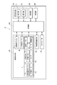
本実施形態に係る画像形成装置10は、電子写真プロセス技術を利用した中間転写方式のカラー画像形成装置であり、図1及び図2に示すように、自動原稿搬送部20、スキャナー部30、画像形成部40、給紙部50、記憶部60、操作表示部70、制御部100等を備えて構成される。
An
自動原稿搬送部20は、原稿Dを載置する載置トレイや原稿Dを搬送する機構及び搬送ローラー等を備えて構成され、原稿Dを所定の搬送路に搬送する。
スキャナー部30は、光源や反射鏡等の光学系を備えて構成され、所定の搬送路を搬送された原稿D又はプラテンガラスに載置された原稿Dに光源を照射し、反射光を受光する。また、スキャナー部30は、受光した反射光を電気信号に変換して制御部100に出力する。
The automatic
The
画像形成部40は、イエロー作像部Y、マゼンタ作像部M、シアン作像部C、ブラック作像部K、中間転写ベルトT、定着装置F等を備えて構成される。
各作像部YMCKは、それぞれイエロー、マゼンタ、シアン、ブラックのトナー像を感光体ドラム41に形成し、感光体ドラム41に形成されたYMCK各色のトナー像を中間転写ベルトTに一次転写する。
なお、各作像部YMCKの構成及び動作は何れも同様であるため、以下、イエロー作像部Yを例に挙げて、画像形成部40が行う一連の画像形成動作について説明する。
The
Each image forming unit YMCK forms yellow, magenta, cyan, and black toner images on the
Since the configuration and operation of each image forming unit YMCK are the same, a series of image forming operations performed by the
感光体ドラム41は、表面がフタロシアニン顔料をポリカーボネイトに分散させた有機半導体層及び電荷輸送層により構成される感光体層により構成される。
帯電装置42は、感光体ドラム41を一様に帯電する。
露光装置43は、制御部100からの画像データDyに基づいて感光体ドラム41の非画像領域を露光して露光した部分の電荷を除去し、感光体ドラム41の画像領域に静電潜像を形成する。
現像装置44は、感光体ドラム41に形成された静電潜像上に現像剤であるトナーを供給し、感光体ドラム41にイエローのトナー像を形成する。
The
The
The
The developing
一次転写ローラー45は、感光体ドラム41に形成されたイエローのトナー像を中間転写ベルトTに一次転写する。
なお、他の作像部MCKも同様に、マゼンタ、シアン、ブラックのトナー像を中間転写ベルトTに一次転写する。これにより、中間転写ベルトT上にYMCK各色のカラーのト ナー像が形成される。
The
Similarly, the other image forming units MCK also primarily transfer magenta, cyan, and black toner images onto the intermediate transfer belt T. As a result, a color toner image of each color of YMCK is formed on the intermediate transfer belt T.
中間転写ベルトTは、複数のローラーに懸架され回転可能に支持された半導電性エンドレスベルトであり、ローラーの回転に伴って回転駆動される。
この中間転写ベルトTは、一次転写ローラー45により、対向するそれぞれの感光体ドラム41に圧着される。一次転写ローラー45のそれぞれには、印加された電圧に応じた転写電流が流れる。これにより、各感光体ドラム41の表面に現像された各トナー像は、それぞれ各一次転写ローラー45により順次中間転写ベルトTに一次転写される。
The intermediate transfer belt T is a semiconductive endless belt that is suspended and supported rotatably by a plurality of rollers, and is driven to rotate as the rollers rotate.
The intermediate transfer belt T is pressed against the respective
二次転写ローラー46は、中間転写ベルトTに押圧されて従回転することで、当該中間転写ベルトTに転写されて形成されたYMCK各色のトナー像を給紙部50の給紙トレイ51〜53から搬送されてきた用紙Pに二次転写する。二次転写ローラー46は、中間転写ベルトTを介して二次転写対向ローラー461に当接して配置され、二次転写ローラー46と二次転写対向ローラー461との間で形成される転写ニップを用紙Pが通過することにより、中間転写ベルトT上のトナー像が、用紙Pに二次転写される。
The
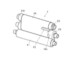
定着装置Fは、図1〜図3に示すように、用紙Pの下面側に配置される加熱搬送ローラー(搬送ローラー)F1と、上面側に配置される定着ローラー(第1ローラー)F2及び定着ローラーF2の上方に配置される加熱ローラー(第2ローラー)F3と、定着ベルトF4と、定着ベルトF4の幅方向端部位置F41を検出するセンサーF5と、加熱ローラーF3を水平方向に移動させるローラー移動部F6(図2参照)と、を備えて構成されている。定着装置Fは、加熱搬送ローラーF1及び定着ローラーF2を加熱して圧接することにより形成されたニップ部に用紙Pを通過させることで用紙Pを加熱及び加圧して、転写されたトナー像を用紙Pに定着させるとともに、当該用紙Pを搬送方向下流側に搬送する。 As shown in FIGS. 1 to 3, the fixing device F includes a heating conveyance roller (conveyance roller) F <b> 1 disposed on the lower surface side of the paper P, a fixing roller (first roller) F <b> 2 disposed on the upper surface side, and fixing. A heating roller (second roller) F3 disposed above the roller F2, a fixing belt F4, a sensor F5 for detecting the end position F41 in the width direction of the fixing belt F4, and a roller for moving the heating roller F3 in the horizontal direction. And a moving part F6 (see FIG. 2). The fixing device F heats and presses the sheet P by passing the sheet P through a nip formed by heating and pressing the heating and conveying roller F1 and the fixing roller F2, and the transferred toner image is transferred to the sheet. In addition to fixing to P, the paper P is transported downstream in the transport direction.
加熱搬送ローラーF1は、ゴムにより円筒状に形成され、加熱ローラーF3と同様、内部に高出力ヒーターを備えている。加熱搬送ローラーF1は、用紙Pの搬送方向に対して順方向に回転し、搬送されてきた用紙Pの非定着面を加熱及び加圧する。なお、加熱搬送ローラーF1は、定着ローラーF2に対して圧着又は離間可能な構成となっており、ニップ部におけるニップ圧を制御可能な構成となっている。
定着ローラーF2は、加熱搬送ローラーF1よりも硬度が低い、スポンジ状の発泡ゴムにより円筒状に形成され、用紙Pの搬送方向に対して順方向に回転し、搬送されてきた用紙Pの定着面を、定着ベルトF4を介して加熱及び加圧する。
加熱ローラーF3は、内部に高出力ヒーターを備えており、用紙Pの搬送方向に対して順方向に回転し、定着ベルトF4を介して定着ローラーF2を加熱する。即ち、加熱ローラーF3は、本発明の加熱部として機能する。
定着ベルトF4は、用紙幅よりも幅広に形成され、定着ローラーF2及び加熱ローラーF3によって張架されて用紙Pの定着面を形成し、用紙Pを加熱する。
The heating / conveying roller F1 is formed in a cylindrical shape from rubber, and has a high-output heater inside, similar to the heating roller F3. The heating conveyance roller F1 rotates in the forward direction with respect to the conveyance direction of the paper P, and heats and pressurizes the non-fixing surface of the conveyed paper P. The heating / conveying roller F1 is configured to be capable of pressure bonding or separation with respect to the fixing roller F2, and is configured to be able to control the nip pressure at the nip portion.
The fixing roller F2 is formed in a cylindrical shape with sponge-like foam rubber having a lower hardness than the heating and conveying roller F1, rotates in the forward direction with respect to the conveying direction of the paper P, and the fixing surface of the conveyed paper P Is heated and pressurized through the fixing belt F4.
The heating roller F3 includes a high-power heater inside, rotates in the forward direction with respect to the conveyance direction of the paper P, and heats the fixing roller F2 via the fixing belt F4. That is, the heating roller F3 functions as the heating unit of the present invention.
The fixing belt F4 is formed wider than the paper width, and is stretched by the fixing roller F2 and the heating roller F3 to form a fixing surface of the paper P, and heats the paper P.
また、加熱ローラーF3は、図4(A)〜図4(C)に示すように、軸方向の一端部F31を中心として水平方向に移動(回動)可能に構成されている。加熱ローラーF3は、制御部100によるローラー移動部F6の制御により、水平方向に移動する。
定着ベルトF4は、加熱ローラーF3の水平方向への移動に連動して、幅方向(加熱ローラーF3及び定着ローラーF2の軸方向)に平行移動するように構成されている。具体的には、定着ベルトF4は、図4(B)に示すように、加熱ローラーF3の用紙搬送方向上流側(図中矢印G1)への移動に連動して、幅方向手前側(図中矢印G2)に移動する。また、定着ベルトF4は、図4(C)に示すように、加熱ローラーF3の用紙搬送方向下流側(図中矢印G3)への移動に連動して、幅方向奥側(図中矢印G4)に移動する。
なお、定着ベルトF4は、加熱ローラーF3の軸方向両端部の位置に設けられた規制部材F7(図5、図7、図8等参照)により、幅方向に平行移動した場合であっても加熱ローラーF3から外れないように規制されている。
Further, as shown in FIGS. 4A to 4C, the heating roller F3 is configured to be movable (rotated) in the horizontal direction around the one end F31 in the axial direction. The heating roller F3 moves in the horizontal direction under the control of the roller moving unit F6 by the
The fixing belt F4 is configured to move in parallel in the width direction (the axial direction of the heating roller F3 and the fixing roller F2) in conjunction with the movement of the heating roller F3 in the horizontal direction. Specifically, as shown in FIG. 4B, the fixing belt F4 is moved in front of the width direction (in the drawing) in conjunction with the movement of the heating roller F3 to the upstream side in the paper conveyance direction (arrow G1 in the drawing). Move to arrow G2). Further, as shown in FIG. 4C, the fixing belt F4 is linked to the movement of the heating roller F3 to the downstream side in the paper conveyance direction (arrow G3 in the figure), and the back side in the width direction (arrow G4 in the figure). Move to.
Note that the fixing belt F4 is heated even when it is translated in the width direction by the regulating members F7 (see FIG. 5, FIG. 7, FIG. 8, etc.) provided at the positions of both ends in the axial direction of the heating roller F3. It is regulated so as not to come off from the roller F3.
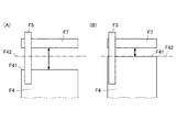
制御部100は、ローラー移動部F6を制御して、加熱ローラーF3を水平方向に移動させることで、定着ベルトF4を幅方向に平行移動させる。制御部100は、図5(A)及び図5(B)に示すように、センサーF5により検出された定着ベルトF4の幅方向手前側の端部位置F41と、定着ベルトF4の移動目標位置F42と、に基づいて、加熱ローラーF3の水平方向への移動量を制御する。なお、移動目標位置F42は、センサーF5により検出された端部位置F41と規制部材F7との間に設定される。制御部100は、端部位置F41から移動目標位置F42までの距離に基づいて、加熱ローラーF3の水平方向への移動量を制御する。
なお、図5では、説明の都合上、加熱ローラーF3の記載を省略している。
The
In FIG. 5, the heating roller F <b> 3 is omitted for convenience of explanation.
以上のように、画像形成部40は、YMCK各色のトナー像が二次転写された用紙を定着装置Fにより加熱及び加圧し、その後所定の搬送路に通して機外に排出する。
以上が画像形成部40による一連の画像形成動作である。
As described above, the
The above is a series of image forming operations by the
クリーニング装置47は、一次転写後の感光体ドラム41表面に残留する残留トナーや紙紛等の残留物を除去する。また、クリーニング装置48は、二次転写後の中間転写ベルトTに残留する残留物を除去する。
クリーニング装置47及びクリーニング装置48は、何れも感光体ドラム41又は中間転写ベルトTに残留する残留物を除去する点で同一であり、同様の構成及び動作を行う。
The
The
給紙部50は、複数の給紙トレイ51〜53を備えて構成され、各給紙トレイ51〜53に種類の異なる複数の用紙Pを収容する。給紙部50は、所定の搬送路により収容される用紙Pを画像形成部40に給紙する。
The
記憶部60は、例えば、HDD(Hard Disk Drive)、半導体メモリなどにより構成され、プログラムデータや各種設定データ等のデータを制御部100から読み書き可能に記憶する。また、記憶部60は、定着ベルトF4の温度(定着温度)と定着ベルトF4の移動可能領域W1との関係を定めたテーブルや、定着ベルトF4の走行距離と定着ベルトF4の移動可能領域W1との関係を定めたテーブル等を記憶する。
The
操作表示部70は、例えば、タッチパネル付の液晶ディスプレイ(LCD)で構成され、表示部71及び操作部72として機能する。
表示部71は、制御部100から入力される表示制御信号に従って、各種操作画面、各機能の動作状況等の表示を行う。また、ユーザーによるタッチ操作を受け付けて、操作信号を制御部100に出力する。
操作部72は、テンキー、スタートキー等の各種操作キーを備え、ユーザーによる各種入力操作を受け付けて、操作信号を制御部100に出力する。ユーザーは、操作表示部70を操作して、画質設定、倍率設定、応用設定、出力設定及び用紙設定等の画像形成に関する設定、用紙搬送指示、並びに装置の停止操作などを行うことができる。
The
The
The
制御部100は、CPU、RAM、ROM等を備えて構成され、CPUはROMに記憶されている各種プログラムをRAMに展開し、展開された各種プログラムと協働して、自動原稿搬送部20、スキャナー部30、画像形成部40、給紙部50、記憶部60、操作表示部70等の画像形成装置10の各部の動作を統括的に制御する(図2参照)。例えば、制御部100は、スキャナー部30からの電気信号を入力して各種画像処理を行い、画像処理により生成されたYMCK各色の画像データDy、Dm、Dc、Dkを画像形成部40に出力する。また、制御部100は、画像形成部40の動作を制御して用紙Pに画像を形成する。
The
次に、本実施形態に係る画像形成装置10の動作について、図6のフローチャートを参照して説明する。
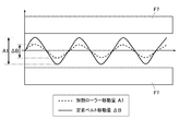
まず、制御部100は、加熱ローラーF3を所定量(ΔB)移動させたときの定着ベルトF4の移動量A1を測定する(ステップS101)。具体的には、制御部100は、図7に示すように、ローラー移動部F6を制御して加熱ローラーF3を所定量(ΔB)移動させるとともに、センサーF5により連続的に検出された定着ベルトF4の端部位置F41を取得することで、加熱ローラーF3の移動に対する定着ベルトF4の移動量A1を測定する。これにより、定着ベルトF4を所定量移動させたいときの加熱ローラーF3の移動量を正確に算出することが可能となる。
Next, the operation of the
First, the
次に、制御部100は、定着ベルトF4の温度(定着温度)及び定着ベルトF4の走行距離に基づいて、定着ベルトF4の移動可能領域W1を設定する(ステップS102)。即ち、制御部100は、本発明の領域設定部として機能する。具体的には、制御部100は、定着温度と移動可能領域W1との関係を定めたテーブルや、定着ベルトF4の走行距離と移動可能領域W1との関係を定めたテーブルを参照することで、移動可能領域W1を設定する。なお、定着温度は、定着装置Fを通紙させる用紙の紙種毎に予め設定されている。例えば、制御部100は、定着温度が高くなればなるほど定着ベルトF4の強度が低下するため、規制部材F7との接触を避けるべく、移動可能領域W1を狭く設定する。また、制御部100は、走行距離が長くなればなるほど定着ベルトF4の強度が低下するため、規制部材F7との接触を避けるべく、移動可能領域W1を狭く設定する。
ここで、定着ベルトF4の移動可能領域W1は、図8に示すように、一対の規制部材F7間の長さをW2とした場合に、W1<W2を満たす条件で設定される。なお、図8では、説明の都合上、加熱ローラーF3の記載を省略している。
Next, the
Here, as shown in FIG. 8, the movable region W1 of the fixing belt F4 is set under a condition that satisfies W1 <W2, where the length between the pair of regulating members F7 is W2. In FIG. 8, the description of the heating roller F3 is omitted for convenience of explanation.
次に、制御部100は、ステップS102で設定された移動可能領域W1に基づいて、定着ベルトF4の移動量Aを設定する(ステップS103)。即ち、制御部100は、本発明の移動量設定部として機能する。具体的には、制御部100は、図8に示すように、定着ベルトF4の幅方向の長さをWとした場合に、定着ベルトF4の移動量Aを、A+W≦W1を満たす条件で設定する。なお、ステップS103で定着ベルトF4の移動量Aが設定されることにより、定着ベルトF4の移動目標位置F42(図5参照)が設定される。
Next, the
次に、制御部100は、ステップS103で設定された定着ベルトF4の移動量AとステップS101の測定結果とを参照して、加熱ローラーF3の移動量を算出する(ステップS104)。次いで、制御部100は、ローラー移動部F6を制御して、ステップS104で算出した移動量に応じて加熱ローラーF3を移動させる(ステップS105)。
即ち、制御部100は、本発明のローラー制御部として機能する。
Next, the
That is, the
以上のように、本実施形態に係る画像形成装置10の定着装置Fは、用紙の下面側に配置される搬送ローラー(加熱搬送ローラーF1)と、搬送ローラーと対向するように、用紙の上面側に配置される第1ローラー(定着ローラーF2)と、第1ローラーの上方に配置される第2ローラー(加熱ローラーF3)と、第2ローラーを、軸方向の一端部を中心として水平方向に移動させるローラー移動部F6と、第1ローラー及び第2ローラーにより張架されて用紙の定着面を形成するとともに、当該第2ローラーの移動に連動して幅方向に平行移動する定着ベルトF4と、定着ベルトF4を加熱する加熱部(加熱ローラーF3)と、定着ベルトF4の幅方向端部の位置を検出するセンサーF5と、センサーF5により検出された定着ベルトF4の幅方向端部の位置と定着ベルトF4の耐久に係る条件とに基づいて、定着ベルトF4の移動可能領域を設定する領域設定部(制御部100)と、領域設定部により設定された定着ベルトF4の移動可能領域に基づいて、定着ベルトF4の移動量を設定する移動量設定部(制御部100)と、移動量設定部により設定された定着ベルトF4の移動量に基づいて、ローラー移動部F6による第2ローラーの移動量を制御するローラー制御部(制御部100)と、を備える。
従って、本実施形態に係る定着装置Fによれば、定着ベルトF4を幅方向に適切に移動させることができるので、定着ベルトF4におけるエッジ傷の発生を抑制することができる。また、定着ベルトF4の耐久を考慮して定着ベルトF4の移動可能領域を調整することができるので、定着ベルトF4の端部の変形や破断を抑制することができる。
As described above, the fixing device F of the
Therefore, according to the fixing device F according to the present embodiment, since the fixing belt F4 can be appropriately moved in the width direction, the occurrence of edge scratches on the fixing belt F4 can be suppressed. Further, since the movable region of the fixing belt F4 can be adjusted in consideration of the durability of the fixing belt F4, deformation and breakage of the end portion of the fixing belt F4 can be suppressed.
また、本実施形態に係る定着装置Fによれば、定着ベルトF4の耐久に係る条件は、定着ベルトF4の温度を含み、領域設定部は、定着ベルトF4の温度が高くなるにつれて、定着ベルトF4の移動可能領域が狭くなるように設定する。
従って、本実施形態に係る定着装置Fによれば、通紙される用紙の紙種毎に設定される定着温度に基づいて定着ベルトF4の耐久度合いを判断したうえで定着ベルトF4の移動可能領域を調整することができるので、定着ベルトF4におけるエッジ傷発生の抑制及び定着ベルトF4端部の変形や破断の抑制を考慮したより適切な移動可能領域を設定することができる。
Further, according to the fixing device F according to the present embodiment, the condition relating to the durability of the fixing belt F4 includes the temperature of the fixing belt F4, and the region setting unit sets the fixing belt F4 as the temperature of the fixing belt F4 increases. The movable area is set to be narrow.
Therefore, according to the fixing device F according to the present embodiment, after determining the durability of the fixing belt F4 based on the fixing temperature set for each paper type of the paper to be passed, the movable region of the fixing belt F4 is determined. Therefore, it is possible to set a more appropriate movable region in consideration of suppression of edge flaws in the fixing belt F4 and suppression of deformation and breakage of the end portion of the fixing belt F4.
また、本実施形態に係る画像形成装置10によれば、定着ベルトF4の耐久に係る条件は、定着ベルトF4の走行距離を含み、領域設定部は、定着ベルトF4の走行距離が長くなるにつれて、定着ベルトF4の移動可能領域が狭くなるように設定する。
従って、本実施形態に係る画像形成装置10によれば、通紙時の定着ベルトF4の走行距離に基づいて定着ベルトF4の耐久度合いを判断したうえで定着ベルトF4の移動可能領域を調整することができるので、定着ベルトF4におけるエッジ傷発生の抑制及び定着ベルトF4端部の変形や破断の抑制を考慮したより適切な移動可能領域を設定することができる。
Further, according to the
Therefore, the
以上、本発明に係る実施形態に基づいて具体的に説明したが、本発明は上記実施形態に限定されるものではなく、その要旨を逸脱しない範囲で変更可能である。 As mentioned above, although concretely demonstrated based on embodiment which concerns on this invention, this invention is not limited to the said embodiment, It can change in the range which does not deviate from the summary.
例えば、上記実施形態では、加熱ローラーF3を水平方向に移動させるようにしているが、これに限定されるものではない。例えば、加熱ローラーF3の代わりに、定着ローラーF2を水平方向に移動させるようにしてもよい。但し、加熱ローラーF3を水平方向に移動させる方が、定着ローラーF2を水平方向に移動させるよりも、定着効率の点でより好ましい。
また、上記実施形態では、加熱部として、加熱ローラーF3を例示して説明しているが、これに限定されるものではない。例えば、加熱ローラーF3の代わりに、定着ローラーF2に加熱機能を備えさせることで、当該定着ローラーF2を加熱部として用いるようにしてもよい。また、定着ベルトF4を加熱可能な他の構成を加熱部として用いるようにしてもよい。
For example, in the above embodiment, the heating roller F3 is moved in the horizontal direction, but the present invention is not limited to this. For example, instead of the heating roller F3, the fixing roller F2 may be moved in the horizontal direction. However, moving the heating roller F3 in the horizontal direction is more preferable in terms of fixing efficiency than moving the fixing roller F2 in the horizontal direction.
Moreover, in the said embodiment, although the heating roller F3 was illustrated and demonstrated as a heating part, it is not limited to this. For example, instead of the heating roller F3, the fixing roller F2 may be provided with a heating function so that the fixing roller F2 is used as a heating unit. Further, another configuration capable of heating the fixing belt F4 may be used as the heating unit.
また、上記実施形態では、定着ベルトF4の移動可能領域W1を設定する際、定着ベルトF4の走行距離に基づいて設定するようにしているが、これに限定されるものではない。例えば、定着ベルトF4の走行距離の代わりに、定着ベルトF4の耐久枚数に基づいて定着ベルトF4の移動可能領域W1を設定するようにしてもよい。この場合、制御部100は、耐久枚数が増えれば増えるほど定着ベルトF4の強度が低下するため、規制部材F7との接触を避けるべく、移動可能領域W1を狭く設定する。
In the above-described embodiment, when the movable region W1 of the fixing belt F4 is set, the setting is made based on the travel distance of the fixing belt F4. However, the present invention is not limited to this. For example, the movable region W1 of the fixing belt F4 may be set based on the durable number of the fixing belt F4 instead of the travel distance of the fixing belt F4. In this case, since the strength of the fixing belt F4 decreases as the number of durable sheets increases, the
また、上記実施形態では、定着温度及び定着ベルトF4の走行距離に基づいて、定着ベルトF4の移動可能領域W1を設定するようにしているが、これに限定されるものではない。例えば、定着温度のみに基づいて移動可能領域W1を設定するようにしてもよいし、定着ベルトF4の走行距離のみに基づいて移動可能領域W1を設定するようにしてもよい。 In the above embodiment, the movable region W1 of the fixing belt F4 is set based on the fixing temperature and the travel distance of the fixing belt F4. However, the present invention is not limited to this. For example, the movable area W1 may be set based only on the fixing temperature, or the movable area W1 may be set based only on the travel distance of the fixing belt F4.
また、定着ベルトF4の移動可能領域W1を設定するための条件としては、定着温度や定着ベルトF4の走行距離に限らず、定着ベルトF4の耐久に係る条件であればいかなる条件であってもよい。例えば、定着温度や定着ベルトF4の走行距離の代わりに、ニップ部におけるニップ圧に基づいて移動可能領域W1を設定するようにしてもよい。この場合、制御部100は、ニップ圧と移動可能領域W1との関係を定めたテーブルを参照することで、移動可能領域W1を設定する。なお、ニップ圧は、定着装置Fを通紙させる用紙の紙種毎に予め設定されている。例えば、制御部100は、ニップ圧が増えれば増えるほど定着ベルトF4と規制部材F7とが接触した時の衝撃が強くなるため、規制部材F7との接触を避けるべく、移動可能領域W1を狭く設定する。
The conditions for setting the movable region W1 of the fixing belt F4 are not limited to the fixing temperature and the travel distance of the fixing belt F4, and any conditions may be used as long as the conditions are related to the durability of the fixing belt F4. . For example, the movable region W1 may be set based on the nip pressure at the nip portion instead of the fixing temperature and the travel distance of the fixing belt F4. In this case, the
上記のように、ニップ部におけるニップ圧に基づいて移動可能領域W1を設定することで、通紙される用紙の紙種毎に設定されるニップ圧に基づいて定着ベルトF4の耐久度合いを判断したうえで定着ベルトF4の移動可能領域を調整することができるので、定着ベルトF4におけるエッジ傷発生の抑制及び定着ベルトF4端部の変形や破断の抑制を考慮したより適切な移動可能領域を設定することができる。
なお、ニップ部におけるニップ圧に加え、定着温度や定着ベルトF4の走行距離に基づいて移動可能領域W1を設定することも当然に可能である。
As described above, by setting the movable region W1 based on the nip pressure in the nip portion, the durability level of the fixing belt F4 is determined based on the nip pressure set for each paper type of the paper to be passed. In addition, since the movable region of the fixing belt F4 can be adjusted, a more appropriate movable region is set in consideration of suppression of edge flaws in the fixing belt F4 and suppression of deformation and breakage of the fixing belt F4 end. be able to.
Of course, it is possible to set the movable region W1 based on the fixing temperature and the travel distance of the fixing belt F4 in addition to the nip pressure in the nip portion.
また、定着ベルトF4の移動量Aを設定する際、A+W≦W1を満たす条件であればいかなる条件で設定されてもよいが、設定する移動量Aを常時変動させる、即ち、定着ベルトF4を常時幅方向に移動させることがより好ましい。上記のように、定着ベルトF4を常時幅方向に移動させることで、定着ベルトF4における用紙との接触部分を常時分散させることができるので、定着ベルトF4の摩耗をより低減させることができる。 Further, when the movement amount A of the fixing belt F4 is set, it may be set under any condition as long as A + W ≦ W1 is satisfied. However, the movement amount A to be set is constantly changed, that is, the fixing belt F4 is always turned on. It is more preferable to move in the width direction. As described above, by constantly moving the fixing belt F4 in the width direction, the contact portion of the fixing belt F4 with the paper can be dispersed at all times, so that wear of the fixing belt F4 can be further reduced.
その他、定着装置及び画像形成装置を構成する各装置の細部構成及び各装置の細部動作に関しても、本発明の趣旨を逸脱することのない範囲で適宜変更可能である。 In addition, the detailed configuration of each apparatus constituting the fixing device and the image forming apparatus and the detailed operation of each apparatus can be appropriately changed without departing from the spirit of the present invention.
10 画像形成装置
20 自動原稿搬送部
30 スキャナー部
40 画像形成部
41 感光体ドラム
42 帯電装置
43 露光装置
44 現像装置
45 一次転写ローラー
46 二次転写ローラー
47、48 クリーニング装置
T 中間転写ベルト
F 定着装置
F1 加熱搬送ローラー(搬送ローラー)
F2 定着ローラー(第1ローラー)
F3 加熱ローラー(第2ローラー、加熱部)
F4 定着ベルト
F5 センサー
F6 ローラー移動部
F7 規制部材
50 給紙部
60 記憶部
70 操作表示部
100 制御部(領域設定部、移動量設定部、ローラー制御部)
DESCRIPTION OF
F2 fixing roller (first roller)
F3 heating roller (second roller, heating section)
F4 fixing belt F5 sensor F6 roller moving unit
Claims (5)
前記用紙の下面側に配置される搬送ローラーと、
前記搬送ローラーと対向するように、前記用紙の上面側に配置される第1ローラーと、
前記第1ローラーの上方に配置される第2ローラーと、
前記第1ローラー及び前記第2ローラーのいずれか一方を、軸方向の一端部を中心として水平方向に移動させるローラー移動部と、
前記第1ローラー及び前記第2ローラーにより張架されて前記用紙の定着面を形成するとともに、当該第1ローラー及び当該第2ローラーのいずれか一方の移動に連動して幅方向に平行移動する定着ベルトと、
前記定着ベルトを加熱する加熱部と、
前記定着ベルトの幅方向端部の位置を検出するセンサーと、
前記センサーにより検出された定着ベルトの幅方向端部の位置と前記定着ベルトの耐久に係る条件とに基づいて、前記定着ベルトの移動可能領域を設定する領域設定部と、
前記領域設定部により設定された定着ベルトの移動可能領域に基づいて、前記定着ベルトの移動量を設定する移動量設定部と、
前記移動量設定部により設定された定着ベルトの移動量に基づいて、前記ローラー移動部による前記第1ローラー及び前記第2ローラーのいずれか一方の移動量を制御するローラー制御部と、
を備えることを特徴とする定着装置。 In a fixing device for fixing a toner image transferred on a sheet to the sheet,
A transport roller disposed on the lower surface side of the paper;
A first roller disposed on the upper surface side of the paper so as to face the transport roller;
A second roller disposed above the first roller;
A roller moving unit that moves one of the first roller and the second roller in a horizontal direction around one end in the axial direction;
Fixing that is stretched by the first roller and the second roller to form a fixing surface of the paper and that moves in parallel in the width direction in conjunction with the movement of either the first roller or the second roller. Belt,
A heating unit for heating the fixing belt;
A sensor for detecting the position of the end in the width direction of the fixing belt;
An area setting unit for setting a movable area of the fixing belt based on the position of the end portion in the width direction of the fixing belt detected by the sensor and a condition relating to durability of the fixing belt;
A moving amount setting unit for setting a moving amount of the fixing belt based on a movable region of the fixing belt set by the region setting unit;
A roller control unit that controls a movement amount of one of the first roller and the second roller by the roller moving unit based on the movement amount of the fixing belt set by the movement amount setting unit;
A fixing device comprising:
前記領域設定部は、前記定着ベルトの温度が高くなるにつれて、前記定着ベルトの移動可能領域が狭くなるように設定することを特徴とする請求項1に記載の定着装置。 The conditions relating to the durability of the fixing belt include the temperature of the fixing belt,
The fixing device according to claim 1, wherein the area setting unit sets the movable area of the fixing belt to be narrowed as the temperature of the fixing belt increases.
前記領域設定部は、前記定着ベルトの走行距離が長くなるにつれて、前記定着ベルトの移動可能領域が狭くなるように設定することを特徴とする請求項1又は2に記載の定着装置。 The conditions relating to the durability of the fixing belt include a travel distance of the fixing belt,
The fixing device according to claim 1, wherein the area setting unit sets the movable area of the fixing belt to be narrowed as the travel distance of the fixing belt becomes longer.
前記領域設定部は、前記ニップ部におけるニップ圧が増えるにつれて、前記定着ベルトの移動可能領域が狭くなるように設定することを特徴とする請求項1〜3のいずれか一項に記載の定着装置。 The conditions relating to the durability of the fixing belt include a nip pressure in a nip portion formed by the transport roller and the first roller,
The fixing device according to claim 1, wherein the region setting unit sets the movable region of the fixing belt to be narrowed as a nip pressure in the nip portion increases. .
前記画像形成部により形成されたトナー像を前記用紙に定着させる請求項1〜4のいずれか一項に記載の定着装置と、
を備えることを特徴とする画像形成装置。 An image forming unit for forming a toner image on paper;
The fixing device according to any one of claims 1 to 4, wherein the toner image formed by the image forming unit is fixed to the paper.
An image forming apparatus comprising:
Priority Applications (1)
| Application Number | Priority Date | Filing Date | Title |
|---|---|---|---|
| JP2015238196A JP2017106948A (en) | 2015-12-07 | 2015-12-07 | Fixing device and image forming apparatus |
Applications Claiming Priority (1)
| Application Number | Priority Date | Filing Date | Title |
|---|---|---|---|
| JP2015238196A JP2017106948A (en) | 2015-12-07 | 2015-12-07 | Fixing device and image forming apparatus |
Publications (1)
| Publication Number | Publication Date |
|---|---|
| JP2017106948A true JP2017106948A (en) | 2017-06-15 |
Family
ID=59059467
Family Applications (1)
| Application Number | Title | Priority Date | Filing Date |
|---|---|---|---|
| JP2015238196A Pending JP2017106948A (en) | 2015-12-07 | 2015-12-07 | Fixing device and image forming apparatus |
Country Status (1)
| Country | Link |
|---|---|
| JP (1) | JP2017106948A (en) |
-
2015
- 2015-12-07 JP JP2015238196A patent/JP2017106948A/en active Pending
Similar Documents
| Publication | Publication Date | Title |
|---|---|---|
| JP6107852B2 (en) | Image forming apparatus and conveyance speed control method | |
| US10082756B2 (en) | Image forming apparatus and image forming system | |
| JP2018097118A (en) | Fixing device and image forming apparatus | |
| US10437186B2 (en) | Fixing device and image forming apparatus | |
| JP6269192B2 (en) | Image forming apparatus | |
| US10386766B2 (en) | Image forming apparatus and feed control method | |
| JP6855761B2 (en) | Fixing device, image forming device and pressure switching method | |
| JP5842797B2 (en) | Image forming apparatus and swing control method | |
| JP6601202B2 (en) | Fixing apparatus, image forming apparatus, and nip shape changing method | |
| JP6372327B2 (en) | Image forming apparatus | |
| JP6052255B2 (en) | Image forming apparatus | |
| JP6086103B2 (en) | Image forming apparatus | |
| JP2017106948A (en) | Fixing device and image forming apparatus | |
| JP6668802B2 (en) | Lubricant application device and image forming device | |
| US9891562B2 (en) | Image forming apparatus and conveyance control method | |
| JP6237184B2 (en) | Fixing apparatus and image forming apparatus | |
| JP7508924B2 (en) | Image forming device | |
| US20210333747A1 (en) | Image forming apparatus | |
| JP2018063387A (en) | Fixing apparatus, image forming apparatus, and control method of image forming apparatus | |
| JP2018025691A (en) | Fixing device, image forming apparatus, and belt shape changing method | |
| JP6443134B2 (en) | Paper posture adjusting device, fixing device, and image forming apparatus | |
| JP2013242478A (en) | Image forming apparatus | |
| JP2021076797A (en) | Life determination device and image forming apparatus | |
| JP2017125954A (en) | Fixing device and image forming apparatus | |
| JP2013186385A (en) | Image forming apparatus |