JP2017106622A - Motion guide device and actuator - Google Patents
Motion guide device and actuator Download PDFInfo
- Publication number
- JP2017106622A JP2017106622A JP2016222882A JP2016222882A JP2017106622A JP 2017106622 A JP2017106622 A JP 2017106622A JP 2016222882 A JP2016222882 A JP 2016222882A JP 2016222882 A JP2016222882 A JP 2016222882A JP 2017106622 A JP2017106622 A JP 2017106622A
- Authority
- JP
- Japan
- Prior art keywords
- main body
- track
- motion guide
- rolling
- frp
- Prior art date
- Legal status (The legal status is an assumption and is not a legal conclusion. Google has not performed a legal analysis and makes no representation as to the accuracy of the status listed.)
- Granted
Links
Images


Classifications
-
- F—MECHANICAL ENGINEERING; LIGHTING; HEATING; WEAPONS; BLASTING
- F16—ENGINEERING ELEMENTS AND UNITS; GENERAL MEASURES FOR PRODUCING AND MAINTAINING EFFECTIVE FUNCTIONING OF MACHINES OR INSTALLATIONS; THERMAL INSULATION IN GENERAL
- F16C—SHAFTS; FLEXIBLE SHAFTS; ELEMENTS OR CRANKSHAFT MECHANISMS; ROTARY BODIES OTHER THAN GEARING ELEMENTS; BEARINGS
- F16C29/00—Bearings for parts moving only linearly
- F16C29/04—Ball or roller bearings
- F16C29/06—Ball or roller bearings in which the rolling bodies circulate partly without carrying load
- F16C29/063—Ball or roller bearings in which the rolling bodies circulate partly without carrying load with a bearing body, e.g. a carriage or part thereof, provided between the legs of a U-shaped guide rail or track
-
- F—MECHANICAL ENGINEERING; LIGHTING; HEATING; WEAPONS; BLASTING
- F16—ENGINEERING ELEMENTS AND UNITS; GENERAL MEASURES FOR PRODUCING AND MAINTAINING EFFECTIVE FUNCTIONING OF MACHINES OR INSTALLATIONS; THERMAL INSULATION IN GENERAL
- F16C—SHAFTS; FLEXIBLE SHAFTS; ELEMENTS OR CRANKSHAFT MECHANISMS; ROTARY BODIES OTHER THAN GEARING ELEMENTS; BEARINGS
- F16C29/00—Bearings for parts moving only linearly
- F16C29/004—Fixing of a carriage or rail, e.g. rigid mounting to a support structure or a movable part
-
- F—MECHANICAL ENGINEERING; LIGHTING; HEATING; WEAPONS; BLASTING
- F16—ENGINEERING ELEMENTS AND UNITS; GENERAL MEASURES FOR PRODUCING AND MAINTAINING EFFECTIVE FUNCTIONING OF MACHINES OR INSTALLATIONS; THERMAL INSULATION IN GENERAL
- F16C—SHAFTS; FLEXIBLE SHAFTS; ELEMENTS OR CRANKSHAFT MECHANISMS; ROTARY BODIES OTHER THAN GEARING ELEMENTS; BEARINGS
- F16C29/00—Bearings for parts moving only linearly
- F16C29/005—Guide rails or tracks for a linear bearing, i.e. adapted for movement of a carriage or bearing body there along
-
- F—MECHANICAL ENGINEERING; LIGHTING; HEATING; WEAPONS; BLASTING
- F16—ENGINEERING ELEMENTS AND UNITS; GENERAL MEASURES FOR PRODUCING AND MAINTAINING EFFECTIVE FUNCTIONING OF MACHINES OR INSTALLATIONS; THERMAL INSULATION IN GENERAL
- F16C—SHAFTS; FLEXIBLE SHAFTS; ELEMENTS OR CRANKSHAFT MECHANISMS; ROTARY BODIES OTHER THAN GEARING ELEMENTS; BEARINGS
- F16C29/00—Bearings for parts moving only linearly
- F16C29/04—Ball or roller bearings
- F16C29/06—Ball or roller bearings in which the rolling bodies circulate partly without carrying load
- F16C29/0602—Details of the bearing body or carriage or parts thereof, e.g. methods for manufacturing or assembly
-
- F—MECHANICAL ENGINEERING; LIGHTING; HEATING; WEAPONS; BLASTING
- F16—ENGINEERING ELEMENTS AND UNITS; GENERAL MEASURES FOR PRODUCING AND MAINTAINING EFFECTIVE FUNCTIONING OF MACHINES OR INSTALLATIONS; THERMAL INSULATION IN GENERAL
- F16C—SHAFTS; FLEXIBLE SHAFTS; ELEMENTS OR CRANKSHAFT MECHANISMS; ROTARY BODIES OTHER THAN GEARING ELEMENTS; BEARINGS
- F16C33/00—Parts of bearings; Special methods for making bearings or parts thereof
- F16C33/30—Parts of ball or roller bearings
- F16C33/58—Raceways; Race rings
- F16C33/62—Selection of substances
-
- F—MECHANICAL ENGINEERING; LIGHTING; HEATING; WEAPONS; BLASTING
- F16—ENGINEERING ELEMENTS AND UNITS; GENERAL MEASURES FOR PRODUCING AND MAINTAINING EFFECTIVE FUNCTIONING OF MACHINES OR INSTALLATIONS; THERMAL INSULATION IN GENERAL
- F16C—SHAFTS; FLEXIBLE SHAFTS; ELEMENTS OR CRANKSHAFT MECHANISMS; ROTARY BODIES OTHER THAN GEARING ELEMENTS; BEARINGS
- F16C35/00—Rigid support of bearing units; Housings, e.g. caps, covers
-
- F—MECHANICAL ENGINEERING; LIGHTING; HEATING; WEAPONS; BLASTING
- F16—ENGINEERING ELEMENTS AND UNITS; GENERAL MEASURES FOR PRODUCING AND MAINTAINING EFFECTIVE FUNCTIONING OF MACHINES OR INSTALLATIONS; THERMAL INSULATION IN GENERAL
- F16H—GEARING
- F16H25/00—Gearings comprising primarily only cams, cam-followers and screw-and-nut mechanisms
- F16H25/18—Gearings comprising primarily only cams, cam-followers and screw-and-nut mechanisms for conveying or interconverting oscillating or reciprocating motions
- F16H25/20—Screw mechanisms
- F16H25/22—Screw mechanisms with balls, rollers, or similar members between the co-operating parts; Elements essential to the use of such members
- F16H25/2204—Screw mechanisms with balls, rollers, or similar members between the co-operating parts; Elements essential to the use of such members with balls
- F16H25/2214—Screw mechanisms with balls, rollers, or similar members between the co-operating parts; Elements essential to the use of such members with balls with elements for guiding the circulating balls
- F16H25/2228—Screw mechanisms with balls, rollers, or similar members between the co-operating parts; Elements essential to the use of such members with balls with elements for guiding the circulating balls the device for circulation forming a part of the screw member
-
- F—MECHANICAL ENGINEERING; LIGHTING; HEATING; WEAPONS; BLASTING
- F16—ENGINEERING ELEMENTS AND UNITS; GENERAL MEASURES FOR PRODUCING AND MAINTAINING EFFECTIVE FUNCTIONING OF MACHINES OR INSTALLATIONS; THERMAL INSULATION IN GENERAL
- F16H—GEARING
- F16H25/00—Gearings comprising primarily only cams, cam-followers and screw-and-nut mechanisms
- F16H25/18—Gearings comprising primarily only cams, cam-followers and screw-and-nut mechanisms for conveying or interconverting oscillating or reciprocating motions
- F16H25/20—Screw mechanisms
- F16H25/22—Screw mechanisms with balls, rollers, or similar members between the co-operating parts; Elements essential to the use of such members
- F16H25/2204—Screw mechanisms with balls, rollers, or similar members between the co-operating parts; Elements essential to the use of such members with balls
- F16H25/2233—Screw mechanisms with balls, rollers, or similar members between the co-operating parts; Elements essential to the use of such members with balls with cages or means to hold the balls in position
- F16H25/2238—Screw mechanisms with balls, rollers, or similar members between the co-operating parts; Elements essential to the use of such members with balls with cages or means to hold the balls in position using ball spacers, i.e. spacers separating the balls, e.g. by forming a chain supporting the balls
-
- F—MECHANICAL ENGINEERING; LIGHTING; HEATING; WEAPONS; BLASTING
- F16—ENGINEERING ELEMENTS AND UNITS; GENERAL MEASURES FOR PRODUCING AND MAINTAINING EFFECTIVE FUNCTIONING OF MACHINES OR INSTALLATIONS; THERMAL INSULATION IN GENERAL
- F16C—SHAFTS; FLEXIBLE SHAFTS; ELEMENTS OR CRANKSHAFT MECHANISMS; ROTARY BODIES OTHER THAN GEARING ELEMENTS; BEARINGS
- F16C2208/00—Plastics; Synthetic resins, e.g. rubbers
- F16C2208/80—Thermosetting resins
- F16C2208/82—Composites, i.e. fibre reinforced thermosetting resins
-
- F—MECHANICAL ENGINEERING; LIGHTING; HEATING; WEAPONS; BLASTING
- F16—ENGINEERING ELEMENTS AND UNITS; GENERAL MEASURES FOR PRODUCING AND MAINTAINING EFFECTIVE FUNCTIONING OF MACHINES OR INSTALLATIONS; THERMAL INSULATION IN GENERAL
- F16C—SHAFTS; FLEXIBLE SHAFTS; ELEMENTS OR CRANKSHAFT MECHANISMS; ROTARY BODIES OTHER THAN GEARING ELEMENTS; BEARINGS
- F16C2226/00—Joining parts; Fastening; Assembling or mounting parts
- F16C2226/30—Material joints
- F16C2226/40—Material joints with adhesive
-
- F—MECHANICAL ENGINEERING; LIGHTING; HEATING; WEAPONS; BLASTING
- F16—ENGINEERING ELEMENTS AND UNITS; GENERAL MEASURES FOR PRODUCING AND MAINTAINING EFFECTIVE FUNCTIONING OF MACHINES OR INSTALLATIONS; THERMAL INSULATION IN GENERAL
- F16C—SHAFTS; FLEXIBLE SHAFTS; ELEMENTS OR CRANKSHAFT MECHANISMS; ROTARY BODIES OTHER THAN GEARING ELEMENTS; BEARINGS
- F16C2226/00—Joining parts; Fastening; Assembling or mounting parts
- F16C2226/50—Positive connections
- F16C2226/52—Positive connections with plastic deformation, e.g. caulking or staking
- F16C2226/54—Positive connections with plastic deformation, e.g. caulking or staking with rivets
-
- F—MECHANICAL ENGINEERING; LIGHTING; HEATING; WEAPONS; BLASTING
- F16—ENGINEERING ELEMENTS AND UNITS; GENERAL MEASURES FOR PRODUCING AND MAINTAINING EFFECTIVE FUNCTIONING OF MACHINES OR INSTALLATIONS; THERMAL INSULATION IN GENERAL
- F16C—SHAFTS; FLEXIBLE SHAFTS; ELEMENTS OR CRANKSHAFT MECHANISMS; ROTARY BODIES OTHER THAN GEARING ELEMENTS; BEARINGS
- F16C2226/00—Joining parts; Fastening; Assembling or mounting parts
- F16C2226/50—Positive connections
- F16C2226/60—Positive connections with threaded parts, e.g. bolt and nut connections
-
- F—MECHANICAL ENGINEERING; LIGHTING; HEATING; WEAPONS; BLASTING
- F16—ENGINEERING ELEMENTS AND UNITS; GENERAL MEASURES FOR PRODUCING AND MAINTAINING EFFECTIVE FUNCTIONING OF MACHINES OR INSTALLATIONS; THERMAL INSULATION IN GENERAL
- F16C—SHAFTS; FLEXIBLE SHAFTS; ELEMENTS OR CRANKSHAFT MECHANISMS; ROTARY BODIES OTHER THAN GEARING ELEMENTS; BEARINGS
- F16C29/00—Bearings for parts moving only linearly
- F16C29/04—Ball or roller bearings
- F16C29/06—Ball or roller bearings in which the rolling bodies circulate partly without carrying load
- F16C29/0602—Details of the bearing body or carriage or parts thereof, e.g. methods for manufacturing or assembly
- F16C29/0609—Details of the bearing body or carriage or parts thereof, e.g. methods for manufacturing or assembly of the ends of the bearing body or carriage where the rolling elements change direction, e.g. end caps
-
- F—MECHANICAL ENGINEERING; LIGHTING; HEATING; WEAPONS; BLASTING
- F16—ENGINEERING ELEMENTS AND UNITS; GENERAL MEASURES FOR PRODUCING AND MAINTAINING EFFECTIVE FUNCTIONING OF MACHINES OR INSTALLATIONS; THERMAL INSULATION IN GENERAL
- F16H—GEARING
- F16H25/00—Gearings comprising primarily only cams, cam-followers and screw-and-nut mechanisms
- F16H25/18—Gearings comprising primarily only cams, cam-followers and screw-and-nut mechanisms for conveying or interconverting oscillating or reciprocating motions
- F16H25/20—Screw mechanisms
- F16H2025/2031—Actuator casings
Abstract
Description
本発明は、運動案内装置と、この運動案内装置を組み込んだアクチュエータに関するものである。 The present invention relates to a motion guide device and an actuator incorporating the motion guide device.
従来から、リニアガイドや直線案内装置、ボールスプライン装置、ボールねじ装置などのような運動案内装置においては、かかる装置を構成する部材が繰り返し転動・摺動動作を伴うことから、その構成部材には、一般的に、高炭素クロム軸受鋼やステンレス鋼、肌焼鋼のような硬度の高い金属材料が採用されている。 Conventionally, in motion guide devices such as linear guides, linear guide devices, ball spline devices, ball screw devices, etc., the members constituting such devices are repeatedly accompanied by rolling and sliding operations. Generally, high-hardness metal materials such as high carbon chromium bearing steel, stainless steel, and case-hardened steel are employed.
しかし、近年の運動案内装置の適用範囲拡大の要請から、特に、軽量化した装置の実現が求められており、この要請に応えるために軽量化のためのアイデアが提案されてきている。例えば、本出願人による下記特許文献1には、鋼などの金属材料並の強度および剛性を有し、且つ、軽量化をも実現する材料である、FRP(Fiber Reinforced Plastics:繊維強化プラスチック)を用いた運動案内装置が提案されている。このFRPは、繊維と樹脂を用いることによってプラスチックを補強し、強度を著しく向上させることができるので、宇宙・航空産業をはじめ、バイク、自動車、鉄道、建設産業、医療分野など、さまざまな分野で用いられている材料である。しかしながら、従来のFRPは、金属材料と比較して耐摩耗性が劣るものであった。そこで、出願人は、運動案内装置に対してFRPを適用する技術を開発し、下記特許文献1において、金属材料のみを用いた技術では実現できなかった軽量化を実現した運動案内装置を提案している。 However, in recent years, there has been a demand for the realization of a weight-reduced device in response to a request for expanding the application range of motion guide devices in recent years, and an idea for weight reduction has been proposed to meet this demand. For example, in the following Patent Document 1 by the present applicant, FRP (Fiber Reinforced Plastics), which is a material that has the same strength and rigidity as a metal material such as steel and also achieves weight reduction, is disclosed. A motion guide device used has been proposed. This FRP can reinforce plastics by using fiber and resin and can significantly improve the strength, so it can be used in various fields such as the space and aviation industries, motorcycles, automobiles, railways, construction industries, medical fields, etc. It is the material used. However, the conventional FRP is inferior in wear resistance as compared with a metal material. Therefore, the applicant has developed a technology that applies FRP to the motion guide device, and in Patent Document 1 below, proposed a motion guide device that has realized weight reduction that could not be realized by the technology using only metal materials. ing.
ところで、FRP製の運動案内装置の構成部材に対して外部部材の取り付けを行う場合には、FRPの積層面にヘリサートを挿入することでネジ孔を形成し、このネジ孔を利用して外部部材の設置が行われていた。しかしながら、FRPの積層面に埋め込み挿入されたヘリサートは、締め付けトルクの管理値以上のトルクで締め付けた場合にヘリサートごと回転してしまい、強度の確保に課題があった。つまり、FRPを用いて構成される運動案内装置には、外部部材を確実に取り付けるための手段の提供が求められていた。 By the way, when attaching an external member to the constituent member of the motion guide device made of FRP, a screw hole is formed by inserting a helicate into the laminated surface of the FRP, and the external member is utilized using this screw hole. Was installed. However, the helicate embedded and inserted in the FRP laminated surface rotates together with the helicate when tightened with a torque equal to or higher than the tightening torque control value, and there is a problem in securing the strength. That is, the motion guide apparatus configured using FRP has been required to provide means for securely attaching the external member.
本発明は、上述した従来技術に存在する課題の存在に鑑みて成されたものであり、その目的は、FRPを用いて構成される運動案内装置において、外部部材を確実に取り付けるための手段を提供することにある。 The present invention has been made in view of the problems existing in the above-described prior art, and an object of the present invention is to provide means for securely attaching an external member in a motion guide apparatus configured using FRP. It is to provide.
本発明に係る運動案内装置は、軌道部材と、前記軌道部材に複数の転動体を介して移動自在に取り付けられる移動部材と、を備える運動案内装置であって、前記軌道部材又は前記移動部材は、前記複数の転動体と接触して転動体転走面を構成する金属材料から成る転走部と、外部部材の取り付けのための取付孔が形成された金属材料から成る取付部と、前記転走部および前記取付部と接合して前記軌道部材又は前記移動部材を形成するFRPから成る軌道本体部又は移動本体部と、から構成され、前記取付部と、前記軌道本体部又は前記移動本体部とは、接合時において前記軌道本体部又は前記移動本体部を構成するFRPの強化繊維シートの積層方向に対して直交する方向に開口した接合穴をそれぞれ有し、当該接合穴に設置される接合手段を用いて接合可能であることを特徴とするものである。 The motion guide device according to the present invention is a motion guide device comprising a track member and a moving member movably attached to the track member via a plurality of rolling elements, the track member or the moving member being A rolling part made of a metal material that contacts the plurality of rolling elements to form a rolling element rolling surface, a mounting part made of a metal material in which a mounting hole for mounting an external member is formed, and the rolling element A track main body or a moving main body made of FRP which joins the running portion and the mounting portion to form the track member or the moving member, and the mounting portion, the track main body or the moving main body. Is a joint that has joint holes opened in a direction orthogonal to the lamination direction of the reinforcing fiber sheets of FRP constituting the track main body part or the movable main body part at the time of joining, and is installed in the joint hole. hand It is characterized in that it is joinable with.
また、本発明に係る別の運動案内装置は、軌道部材と、前記軌道部材に複数の転動体を介して移動自在に取り付けられる移動部材と、を備える運動案内装置であって、前記軌道部材又は前記移動部材は、前記複数の転動体と接触して転動体転走面を構成する金属材料から成る転走部と、外部部材の取り付けのための取付孔が形成された金属材料から成る取付部と、前記転走部および前記取付部と接合して前記軌道部材又は前記移動部材を形成するFRPから成る軌道本体部又は移動本体部と、から構成され、前記取付部と、前記軌道本体部又は前記移動本体部とは、接合時において前記軌道本体部又は前記移動本体部を構成するFRPの強化繊維シートの積層方向に対して平行方向に拡がる接合面をそれぞれ有し、当該接合面に付与される接合手段を用いて接合可能であることを特徴とするものである。 Further, another motion guide device according to the present invention is a motion guide device comprising a track member and a moving member movably attached to the track member via a plurality of rolling elements, the track member or The moving member is a mounting part made of a metal material in which a rolling part made of a metal material that makes contact with the plurality of rolling elements to form a rolling element rolling surface and a mounting hole for mounting an external member are formed. And a track main body or a moving main body made of FRP that joins the rolling portion and the mounting portion to form the track member or the moving member, and the mounting portion, the track main body portion or The moving main body portion has a bonding surface that extends in a direction parallel to the lamination direction of the reinforcing fiber sheets of FRP constituting the track main body portion or the moving main body portion at the time of bonding, and is given to the bonding surface. Contact It is characterized in that it is joinable using means.
なお、本発明では、上記のいずれかの運動案内装置を組み込むことでアクチュエータを構成することができる。 In the present invention, an actuator can be configured by incorporating any of the motion guide devices described above.
本発明によれば、FRPを用いて構成される運動案内装置において、外部部材を確実に取り付けるための手段を提供することができる。また、本発明によれば、この運動案内装置を組み込んだアクチュエータを提供することができる。 ADVANTAGE OF THE INVENTION According to this invention, the means for attaching an external member reliably can be provided in the movement guide apparatus comprised using FRP. Moreover, according to the present invention, an actuator incorporating this motion guide device can be provided.
以下、本発明を実施するための好適な実施形態について、図面を用いて説明する。なお、以下の各実施形態は、各請求項に係る発明を限定するものではなく、また、各実施形態の中で説明されている特徴の組み合わせの全てが発明の解決手段に必須であるとは限らない。 DESCRIPTION OF EMBODIMENTS Hereinafter, preferred embodiments for carrying out the present invention will be described with reference to the drawings. The following embodiments do not limit the invention according to each claim, and all combinations of features described in each embodiment are essential to the solution means of the invention. Not exclusively.
なお、本明細書における「運動案内装置」は、例えば、工作機械などに用いられる転がり軸受全般や真空中で使用される無潤滑軸受、リニアガイドや直線案内装置、ボールスプライン装置、ボールねじ装置、ローラーリングなどのような、あらゆる転動・摺動動作を伴う装置を含むものである。 The “motion guide device” in this specification includes, for example, rolling bearings used in general for machine tools and the like, non-lubricated bearings used in vacuum, linear guides and linear guide devices, ball spline devices, ball screw devices, It includes devices with any rolling / sliding motion such as roller rings.
[第一の実施形態]
図1および図2は、第一の実施形態に係る運動案内装置の一形態を示す図であり、特に、図1は、第一の実施形態に係る運動案内装置の概略構造を説明するための斜視分断図であり、図2は、第一の実施形態に係る運動案内装置の縦断面図である。
[First embodiment]
FIG. 1 and FIG. 2 are views showing an embodiment of the motion guide device according to the first embodiment. In particular, FIG. 1 is for explaining the schematic structure of the motion guide device according to the first embodiment. FIG. 2 is a longitudinal sectional view of the motion guide device according to the first embodiment.
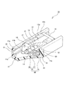
この運動案内装置10は、リニアモーションガイドとボールねじが組み合わされて一体構造となっている形式の運動案内装置10を示すものである。そして、このボールねじが、不図示のモータに接続されることで、本発明に係るアクチュエータとして機能する。
This
第一の実施形態に係る運動案内装置10の主な構造としては、軌道部材としての軌道レール11と、その軌道レール11に転動体としての複数のボール12を介して移動自在に取り付けられた移動部材13とを備えている。また、移動部材13の中央部には、螺旋状のねじ溝が形成された開口部13bが設けられており、かかる開口部13bには、この開口部13bに導通するとともに、ボール12を介して回転移動自在に取り付けられたねじ軸14が設けられている。
The main structure of the
軌道レール11は縦断面が略U字形をした長尺の部材であり、その内側両側面にはボール12を受け入れ可能な転動体転走溝11aが左右2条ずつ軌道レール11の全長に亘って形成されている。軌道レール11の縦断面略U字形の底面側には、その長手方向に適宜間隔をおいて複数のボルト取付孔11bが形成されている。これらボルト取付孔11bに螺着されるボルト(不図示)により、軌道レール11が所定の取付面、例えば工作機械のベッドの上面に固定されることになる。なお、図示の軌道レール11は直線状であるが、曲線状のレールが使用されることもある。
The
移動部材13は、鋼などの強度の高い金属材料に孔を空けた構造のブロックとして構成されている。この移動部材13には、軌道レール11が有する4条の転動体転走溝11aとそれぞれ対向する4条の負荷転動体転走溝13aが設けられている。これら転動体転走溝11aと負荷転動体転走溝13aの組み合わせにより、軌道レール11と移動部材13との間に4条の負荷転動体転走路15が形成される。また、移動部材13の上面13cには複数(図1で見えているのは3本、実際には4本)の雌ねじ13dが形成されている。これらの雌ねじ13dを利用して、移動部材13が所定の取付面、例えば工作機械のサドルやテーブルの下面に固定されることになる。なお、移動部材13については、金属材料のみによって構成されるものだけでなく、鋼などの強度の高い金属材料と一体に射出成形された合成樹脂製の型成形体を含む構造とすることも可能である。
The moving
移動部材13には、4条の負荷転動体転走路15と並行して延びる4条の戻し通路16が形成されている。また、移動部材13は、その両端面に蓋体18を有しており、この蓋体18に形成されるアーチ状に陥没する図示しないボール案内溝によって、負荷転動体転走路15と戻し通路16との間でアーチ状に突出して形成される方向転換路17(図1では、1コーナ側のみ2条の方向転換路17を、蓋体18を除いた状態で示す)を形成する。
In the moving
一対の蓋体18が移動部材13端部を構成する部材として確実に固定されることにより、それらの間に負荷転動体転走路15と戻し通路16とを結ぶ方向転換路17が形成される。戻し通路16と方向転換路17とによってボール12の無負荷転動体転走路19が構成され、その無負荷転動体転走路19と負荷転動体転走路15との組み合わせによって無限循環路20が構成される。
When the pair of
また、第一の実施形態に係る運動案内装置10のボール12間には、ボール12よりも柔らかいスペーサ部材21が設置されている。なお、図1において例示するスペーサ部材21については、軌道レール11と移動部材13の間に設置されるものには帯状のスペーサ部材21が採用されており、一方、移動部材13とねじ軸14の間に設置されるものにはボール12間に1個ずつ挿入されるリテーナとしてのスペーサ部材21が採用されている。ただし、スペーサ部材21の種類や設置の組み合わせについては、図1に例示するものに限られず、例えば、転動体であるボール12の径以下の径を持つスペーサボールなどを採用することが可能である。このようにして設置されるスペーサ部材21は、ボール12同士の干渉や衝突、ボール12の脱落などを防止できるとともに、ボール12の整列運動を実現し、さらにはスペーサ部材21の自己潤滑効果も相まって、運動案内装置10の耐摩耗性を大きく改良できるという効果を発揮する。
A
ここで、第一の実施形態に係る運動案内装置10の特徴的な点として、軌道部材としての軌道レール11は、ボール12と接触する転動体転走面(転動体転走溝11a)の近傍が金属材料によって形成されており、その他の部分がFRPによって形成されていることが挙げられる。かかる特徴を有することによって、第一の実施形態に係る運動案内装置10は、従来の運動案内装置と同等以上の強度および剛性を維持し、且つ、軽量化をも実現することができる。
Here, as a characteristic point of the
第一の実施形態に係る軌道レール11の構造を、図3を用いてより詳細に説明する。図3は、第一の実施形態に係る軌道レール11の構造を説明するための縦断面図である。
The structure of the
第一の実施形態に係る軌道レール11は、金属材料から成る転走部30と、FRPから成る軌道本体部31という2つの部材を接合することによって構成されている。金属材料から成る転走部30は、高い強度と剛性が求められるとともに耐摩耗性をも必要とされる部材である。転走部30に用いられる金属材料としては、例えば、高炭素クロム軸受鋼やステンレス鋼、肌焼鋼のような硬度の高いものを採用できる他、アルミニウム合金やベリリウム銅、チタン合金などを採用することが可能である。
The
一方、軌道本体部31はFRPによって形成されており、第一の実施形態に係る運動案内装置10の軽量化を実現している。採用されるFRPの種類については、CFRP(Carbon Fiber Reinforced Plastics:炭素繊維強化プラスチック)、GFRP(Glass Fiber Reinforced Plastics:ガラス繊維強化プラスチック)、KFRP(Kevlar Fiber Reinforced Plastics:アラミド繊維強化プラスチック)の少なくとも1つであることが好適である。特に、CFRPは、強度の面で大変優れており、カーボン繊維の積層方向や積層数を変化させることによって、所望の形状に対して強度を持たせ、且つ、軽量化を図ることができるので、好ましい材料である。
On the other hand, the track
なお、図1、図2および図3に示した第一の実施形態に係る運動案内装置10においては、軌道レール11のみを金属材料とFRPとで構成するようにしたが、本発明は、かかる実施形態に限られるものではなく、図4に示すように、移動部材13又はねじ軸14に対して適用することも可能である。すなわち、軌道レール11が有する4条の転動体転走溝11aと協働して負荷転動体転走路15を形成している4条の負荷転動体転走溝13aの近傍を金属材料から成る転走部40によって形成したり、4条の負荷転動体転走路15と並行して延びる4条の戻し通路16の近傍を金属材料から成る転走部41によって形成したり、あるいは、ボール12を介してねじ軸14が設置される開口部13bの近傍を金属材料から成る転走部42によって形成したり、さらには、ボール12と接するねじ軸14の外周部分を金属材料から成る転走部44によって形成したりし、その他の部分をFRPから成る移動本体部43として構成することができる。軌道レール11だけでなく、移動部材13又はねじ軸14をもこのような金属材料とFRPとを接合した構造とすることによって、さらなる軽量化を実現することが可能となる。
In addition, in the
また、金属材料から成る転走部30とFRPから成る軌道本体部31、金属材料から成る転走部40,41,42とFRPから成る移動本体部43、あるいは、金属材料から成る転走部44とFRPから成るねじ軸14のその他の部分との接合方法については、接着接合、圧入接合又はボルト接合のうちのいずれか、あるいはこれらを組み合わせた方法を採用することができる。
Further, the rolling
例えば、図3において示すような軌道レール11の場合には、接着剤を用いて接着接合することが好適である。また、図4において示すような移動部材13の場合、負荷転動体転走溝13aの近傍を形成する転走部40にあっては接着剤を用いて接着接合することが好適であり、戻し通路16の近傍や開口部13bの近傍を形成する転走部41,42にあっては圧入接合を採用することが好適である。圧入接合については、転走部41,42の外周面、あるいは、戻し通路16や開口部13bの内周面にローレット加工を施し、圧入することによって確実に接合することができる。さらに、接合強度を増すためにボルト接合を採用することも可能であり、より確実な接合方法として、接着接合とボルト接合、圧入接合とボルト接合を組み合わせた接合方法を採用することも可能である。ただし、ボルト接合の場合には、ボルトの頭部などが運動案内装置10の動作に影響を与えないように配慮する必要がある。なお、ねじ軸14のような形状の部材に関しては、外観形状や材質などに応じて、適宜最適な接合方法を採用すればよい。
For example, in the case of the
以上、図1〜図4を用いることによって、第一の実施形態に係る運動案内装置10の基本的な構成を説明した。次に、第一の実施形態に係る運動案内装置10のさらなる特徴点について、図5〜図7を用いて説明を行う。ここで、図5は、第一の実施形態に係る運動案内装置10の使用状態の一例を示す外観斜視図であり、図6は、第一の実施形態に係る運動案内装置10の構成部材であるFRPの特性を説明するための模式図であり、図7は、第一の実施形態に係る運動案内装置10の要部を説明するための図である。
As described above, the basic configuration of the
上述した第一の実施形態に係る運動案内装置10については、例えば図5で示すように、軌道レール11の長手方向の両端部には、エンドハウジング51,52が取り付けられることがある。このエンドハウジング51,52は、回転移動自在なねじ軸14を支承したり、外部の動力源を取り付けるために用いられたり、あるいは、ねじ軸14等の運動案内装置10の構成部材の調整代として用いられたりする部材である。したがって、これらエンドハウジング51,52については、所定以上の取付精度が求められる部材である。
For the
しかしながら、背景技術の欄で説明した通り、単にFRP製の軌道レール11の長手方向の両端部に対してネジ孔を空けたりヘリサートを設置したりしてエンドハウジング51,52を取り付けたのでは、強度の確保に課題があった。かかる原因について図6を用いて説明すると、図6中の分図(a)で示すように、第一の実施形態に係る軌道レール11の軌道本体部31は、FRPの強化繊維シートSを複数積層する形式で構成されている。したがって、図6中の分図(b)で示すように、第一の実施形態に係る軌道レール11では、FRPの強化繊維シートSの積層方向に対して直交する方向である符号αの方向に力を受けた場合、FRPは大きな強度を発揮することができるが、FRPの強化繊維シートSの積層方向に対して平行な方向である符号βの方向に力を受けた場合、FRPは小さな強度しか発揮することができないという特性を有している。つまり、軌道レール11を構成するFRPの強化繊維シートSの積層方向に対して平行な方向である符号βの方向に向けてネジ孔を空けたりヘリサートを設置したりしてエンドハウジング51,52の取り付けを行ったのでは、強度の確保に課題があった。
However, as explained in the background art section, if the
以上の事項を考慮した上で、本発明者らは、図7で示す新たな構成を創案した。すなわち、FRPで構成された軌道本体部31の端部に段落ち加工部71を形成し、この段落ち加工部71が形成された箇所に嵌り込むように、金属材料から成る取付部75を形成した。この取付部75は、エンドハウジング51,52等の外部部材の取り付けのための取付孔76が形成された部材であり、その全体が金属材料によって構成されている。また、段落ち加工部71は、取付部75の外郭形状に沿った形状として形成されているので、段落ち加工部71に対して取付部75を嵌め込むと、外形寸法が揃った滑らかな外郭形状となって、長尺の部材としての軌道レール11の外形が形成されることとなる。
In consideration of the above matters, the present inventors have created a new configuration shown in FIG. That is, the stepped
さらに、取付部75と、軌道本体部31に形成された段落ち加工部71の箇所には、接合時において、軌道本体部31を構成するFRPの強化繊維シートSの積層方向に対して直交する方向(つまり、図6の分図(b)における符号αの方向)に開口した接合穴72,73,77,78がそれぞれ形成されている。
Furthermore, the
第一の実施形態の接合穴72,73,77,78は、縦断面が略U字形をした軌道レール11の底面側を向く第一の方向に向けて開口した接合穴72,77と、縦断面が略U字形をした軌道レール11の左右面側を向くとともに第一の方向に直交する第二の方向に向けて開口した接合穴73,78との二方向に向けて開口するように複数形成されており、これら二方向に向けて開口した接合穴72,73,77,78を利用することで、軌道本体部31に形成された段落ち加工部71の箇所に対する取付部75の接合が可能となる。なお、当該接合穴72,73,77,78に設置される接合手段については、例えばボルト又はリベットのいずれか1つ若しくはこれらの組み合わせで構成することができ、図7に示された第一の実施形態では、ボルト80を用いた接合手段が例示されている。
The joint holes 72, 73, 77, 78 of the first embodiment are formed by connecting the
また、ボルト80が有する雄ネジによって作用される接合力は、ボルト80の先端部が螺合する部材に及ぶことで高まることとなる。例えば、上述した第一の方向に向けて開口する接合穴72,77とボルト80の関係については、段落ち加工部71に形成された接合穴72をボルト軸径よりも大きい寸法としておき、取付部75に形成された接合穴77にのみ雌ネジを形成することで、ボルト80からの接合力が取付部75のみに作用し、段落ち加工部71が形成された軌道本体部31は、ボルト80と取付部75によって挟み込まれるように構成することができる。また同様に、上述した第二の方向に向けて開口する接合穴73,78とボルト80の関係については、取付部75に形成された接合穴78をボルト軸径よりも大きい寸法としておき、段落ち加工部71に形成された接合穴73にのみ雌ネジを形成することで、ボルト80からの接合力が段落ち加工部71のみに作用し、取付部75は、ボルト80と段落ち加工部71によって挟み込まれるように構成することができる。このような構成を採用することで、ボルト80等の接合手段を用いた取付部75と段落ち加工部71との接合において両部材間に取り付けの際の遊び代ができるので、取付位置の調整が容易となり好ましい。
Further, the joining force applied by the male screw of the
また、第一の実施形態の接合穴72,73,77,78は、軌道本体部31を構成するFRPの強化繊維シートSの積層方向に対して直交する方向(つまり、図6の分図(b)における符号αの方向)に開口しているので、ボルト80等の接合手段から作用される接合力は、FRPの強化繊維シートSの積層方向に対して直交する方向に作用することとなる。つまり、FRPによって構成される軌道本体部31は、強固な力でボルト80等の接合手段から作用される接合力を受容することができるので、FRPによって構成される軌道本体部31と、金属材料からなる取付部75との強固で高精度な接合が実現されることとなる。
Further, the joining
さらに、軌道レール11とエンドハウジング51,52等の外部部材との取り付けは、金属材料からなる取付部75が有する取付孔76によって実行されることとなるが、取付部75は軌道本体部31に対して確実に固定されているとともに、当該取付孔76は金属材料によって形成されているので、背景技術の欄で説明した従来技術の課題は解消され、第一の実施形態に係る軌道レール11に対する外部部材の確実かつ高精度の取付状態が実現されることとなる。
Further, the attachment between the
またさらに、第一の実施形態に係る取付部75は、金属材料によって形成されていることから、軌道本体部31に対して接合した後に、例えば、取付部75の端面を研削加工等することで、当該端面の直角度を確保することも可能となる。すなわち、FRPのみで構成される軌道レールの場合には、金属材料程の外形寸法精度が出ないが、第一の実施形態のように、FRP製の軌道本体部31と金属材料製の取付部75を組み合わせて軌道レール11を構成することで、さらに高い外形寸法精度を有する軌道レール11を実現することが可能となる。
Furthermore, since the
以上、第一の実施形態に係る運動案内装置10のさらなる特徴点について、図5〜図7を用いて説明を行った。図5〜図7を用いて説明した本発明の特徴は、軌道レール11に対して適用した事例を説明するものであったが、かかる特徴事項は、移動部材13に対しても適用することが可能であり、その具体例を図8に示す。ここで、図8は、第一の実施形態を移動部材に適用した事例を示す図である。
As mentioned above, the further characteristic point of the exercise |
図8で例示する移動部材83の場合、すべてがCFRPで形成されている。また、この移動部材83の両端面に設置される蓋体18についても、樹脂にて形成されている。このとき、単に移動部材83に対して蓋体18を、ボルト80を用いて締結したのでは、このボルト80はCFRPの強化繊維シートSの積層方向に対して平行な方向で締結固定されることになるので、その締結力は移動部材83を構成するCFRPの特性上、小さな強度しか発揮することができない。そこで、図8で示す実施形態の場合には、CFRPで形成された移動部材83の両端面の近傍に矩形の切込みを形成し、この切込みに対して金属材料製の締結金具85を挿入することとした。この締結金具85には、移動部材83に挿入された際の側面方向(図8における紙面右斜め下方向)に対して接合穴88が形成されており、この接合穴88の開口方向は、CFRPの強化繊維シートSの積層方向に対して垂直な方向となっている。そして、この接合穴88に対して締結用ノックピン80aを差し込むことで、移動部材83に対する締結金具85の確実かつ強固な接合状態が実現されることとなる。
In the case of the moving
また、締結金具85の端面方向(図8における紙面左斜め下方向)には、蓋体18を取り付けるための取付孔86が形成されており、この取付孔86とボルト80を利用することで、CFRP製の移動部材83に対する樹脂製の蓋体18の強固な取り付けが実現することとなる。
In addition, an
なお、上述した軌道レール11についての第一の実施形態の場合と同様に、図8で例示した締結金具85についても、金属材料によって形成されていることから、移動部材83に対して接合した後に端面を研削加工等することで、当該端面の直角度を確保することが可能となる。すなわち、CFRPのみで構成される移動部材の場合には、金属材料程の外形寸法精度が出ないが、この実施形態のように、CFRP製の移動部材83と金属材料製の締結金具85を組み合わせて構成することで、さらに高い外形寸法精度を有する移動部材83を実現することが可能となる。
Note that, similarly to the case of the first embodiment of the
以上説明した第一の実施形態に係る運動案内装置10によって、外部部材を確実に取り付けるための手段を備えた、FRPを用いて構成される運動案内装置10が実現可能となる。かかる運動案内装置10によれば、FRPの適用に際して課題となっていた外部部材の取付性を改善しつつ、FRPの利点である必要強度を確保しつつ軽量化を実現することが可能となる。なお、アルミ等に代表される非鉄金属は、軽量化を達成することは可能であるが、強度が弱いという課題を有していた。すなわち、鉄のヤング率が206GPaであるところ、アルミのヤング率は約68GPaである。したがって、アルミ等に代表される非鉄金属によって運動案内装置を構成した場合、軽量化は達成できるものの、鉄系材料並みの必要強度を確保することは困難であった。
With the
一方、FRPについては、非常に高いヤング率を実現することが可能であり、例えば、CFRPのヤング率は約50〜400GPaを確保することができる。そして、上述した第一の実施形態のように、CFRPの強化繊維シートSの積層方向に対して直交する方向に力を受けるようにCFRPを用いることで、CFRPはヤング率の上限値である400GPaに近い強度を発揮することが可能となる。つまり、本発明を適用した運動案内装置10によれば、FRPの適用に際して課題となっていた外部部材の取付性を改善しつつ、FRPの利点である必要強度を確保しつつ軽量化を実現することが可能となる。
On the other hand, for FRP, it is possible to achieve a very high Young's modulus. For example, the Young's modulus of CFRP can ensure about 50 to 400 GPa. And like 1st embodiment mentioned above, CFRP is 400 GPa which is the upper limit of Young's modulus by using CFRP so that it may receive force in the direction orthogonal to the lamination direction of CFRP reinforcing fiber sheet S. It is possible to exhibit a strength close to. That is, according to the
また、FRPは、減衰特性に優れた材料であるため、運動案内装置10に適用した場合に有利な効果を発揮することとなる。例えば、運動案内装置10を片持ちで使用した場合などでは、振動が収まるまでの停止時間が短くなるという効果が得られることとなる。つまり、使用環境の制約によって運動案内装置10を片持ちで設置しなければならない場合であっても、外部影響によって発生する振動をFRPの減衰特性によって早期に解消することができるので、運動案内装置10の定常状態復帰サイクルのタクトアップが可能になる。
Further, since FRP is a material having excellent damping characteristics, it exerts an advantageous effect when applied to the
以上、本発明の好適な実施形態について説明したが、本発明の技術的範囲は上記第一の実施形態に記載の範囲には限定されない。上記第一の実施形態には、多様な変更又は改良を加えることが可能である。 The preferred embodiments of the present invention have been described above, but the technical scope of the present invention is not limited to the scope described in the first embodiment. Various modifications or improvements can be added to the first embodiment.
例えば、図7で例示した第一の実施形態に係る軌道レール11では、金属材料から成る取付部75が略L字形の外形を有しており、当該取付部75を取り付けるための段落ち加工部71は、軌道レール11の左右側面と底面とにわたって形成されていた。しかしながら、本発明に係る段落ち加工部と、この段落ち加工部に接合される取付部の形状については、任意に変更が可能である。例えば、図9で示すように、段落ち加工部91を軌道レール11の左右側面のみに形成しておき、この段落ち加工部91の形状に沿った形状を有する取付部95をボルト80により接合するようにしても良い。図9で示す形態の場合も、ボルト80が接合される方向が軌道レール11を構成するFRPの強化繊維シートSの積層方向に対して垂直な方向となっているので、軌道レール11に対する取付部95の確実かつ強固な接合状態が実現されることとなる。なお、図9は、第一の実施形態に係る運動案内装置が取り得る多様な変形例の一例を示す図であり、上述した第一の実施形態の場合と同一又は類似する部材については、同一符号を付すことで説明を省略した。
For example, in the
また例えば、図7で例示した第一の実施形態に係る軌道レール11のように、軌道レール11の左右側面と底面とにわたって段落ち加工部71を形成しておき、この段落ち加工部71に接合される取付部を、2つの側面用取付部95aと1つの底面用取付部95bとに分割して構成することも可能である。その様な形態例を、図10に示す。図10は、第一の実施形態に係る運動案内装置が取り得る多様な変形例のうち、別の一例を示す図であり、上述した第一の実施形態の場合と同一又は類似する部材については、同一符号を付すことで説明を省略してある。図10で例示する形態例の場合も、接合穴72,73,77,78は、軌道本体部31を構成するFRPの強化繊維シートSの積層方向に対して直交する方向(つまり、図6の分図(b)における符号αの方向)に開口しているので、ボルト80等の接合手段から作用される接合力は、FRPの強化繊維シートSの積層方向に対して直交する方向に作用することとなる。つまり、FRPによって構成される軌道本体部31は、強固な力でボルト80等の接合手段から作用される接合力を受容することができるので、FRPによって構成される軌道本体部31と、金属材料からなる側面用取付部95aおよび底面用取付部95bとの強固で高精度な接合が実現されることとなる。
Further, for example, like the
[第二の実施形態]
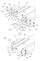
次に、本発明が取り得る別の形態例として、図11を用いることで第二の実施形態に係る運動案内装置200についての説明を行う。ここで、図11は、第二の実施形態に係る運動案内装置の要部を示す部分斜視図であり、図中の分図(a)には段落ち加工部に対する取付部の取り付け前の状態が示されており、分図(b)には段落ち加工部に対する取付部の取り付け後の状態が示されている。なお、図11において、上述した第一の実施形態の場合と同一又は類似する部材については、同一符号を付すことで説明を省略した。
[Second Embodiment]
Next, as another form example that the present invention can take, the
第二の実施形態に係る運動案内装置200では、上述した第一の実施形態の場合と同様に、FRPで構成された軌道本体部31の端部に段落ち加工部71が形成されており、この段落ち加工部71が形成された箇所に嵌り込むように、金属材料から成る取付部75を接合することとした。ただし、第二の実施形態における接合手段には接着剤が用いられるため、第一の実施形態とは異なる構成が採用されている。すなわち、第二の実施形態において、軌道本体部31の端部に形成された段落ち加工部71には、外部部材の取り付けのための取付孔が形成されておらず、また、第二の実施形態に係る段落ち加工部71は、軌道本体部31を構成するFRPの強化繊維シートの積層方向に対して平行方向に拡がる接合面として構成されている。そして、当該接合面である段落ち加工部71に対して接着剤を付与し、取付部75を接合することで、第二の実施形態に係る運動案内装置200の軌道レール211を作製している。
In the
なお、第二の実施形態においても、取付部75には、エンドハウジング51,52等の外部部材の取り付けのための取付孔76が形成されており、その全体が金属材料によって構成されている。また、段落ち加工部71は、取付部75の外郭形状に沿った形状として形成されているので、段落ち加工部71に対して取付部75を接着すると、外形寸法が揃った滑らかな外郭形状となって、長尺の部材としての軌道レール11の外形が形成されることとなる。さらに、第二の実施形態では、接合手段として接着剤を用いているので、段落ち加工部71に対する取付部75の位置決めが容易であるという利点を有している。つまり、第二の実施形態に係る運動案内装置200によれば、FRPの適用に際して課題となっていた外部部材の取付性を改善しつつ、FRPの利点である必要強度を確保しつつ軽量化を実現することが可能となる。
Also in the second embodiment, the mounting
[第三の実施形態]
以上説明した第一および第二の実施形態に係る運動案内装置10,200では、FRPで構成された軌道本体部31の端部に段落ち加工部71を形成しておき、この段落ち加工部71が形成された箇所に嵌り込むように、金属材料から成る取付部75を接合するものであった。しかしながら、本発明の適用範囲は、軌道本体部31の端部に対してのみ適用されるものではなく、例えば、軌道レール11の縦断面略U字形の底面側であって、その長手方向に適宜間隔をおいて複数形成されるボルト取付孔に対しても適用することができる。その具体例を、図12および図13を用いて説明する。ここで、図12は、第三の実施形態に係る運動案内装置を説明するための図であり、図中の分図(a)は運動案内装置の全体構成を示す斜視図であり、分図(b)はボルト取付孔の周辺を示す要部縦断面図であり、分図(c)は軌道レールの構成部材であるFRPの特性を説明するための模式図である。また、図13は、第三の実施形態の具体的な実施事例を示す図である。
[Third embodiment]
In the
図12に示すように、第三の実施形態に係る運動案内装置300では、軌道レール311の縦断面略U字形の底面側には、その長手方向に適宜間隔をおいて複数のボルト取付孔311bが形成されている。そして、図12中の分図(b)で示すように、第三の実施形態に係るボルト取付孔311bは、縦方向に開口したボルト取付孔311bの中央部分で孔の径が変更されている。すなわち、軌道レール311の上方側の孔は開口径が大きく形成されており、一方、軌道レール311の下方側の孔は開口径が小さく形成されている。つまり、第三の実施形態に係るボルト取付孔311bには、本発明に係る段落ち加工部が形成されているのである。さらに、図12中の分図(c)で示すように、当該段落ち加工部を有するボルト取付孔311bは、軌道本体部331を構成するFRPの強化繊維シートSの積層方向に対して直交する方向(つまり、図6の分図(b)における符号αの方向)に開口しているので、FRPが大きな強度を発揮し得る構成が採用されている。
As shown in FIG. 12, in the
そして、上述した段落ち加工部を有するボルト取付孔311bに対しては、上方に鍔部を有する金属カラー375が接着剤によって接着接合されている。この金属カラー375は、外部部材の取り付けのための取付孔376が形成された金属材料から成る部材であり、本発明に係る取付部として機能するものである。
And the
以上のように構成された第三の実施形態に係るボルト取付孔311bおよび金属カラー375に対して、図13で示すようなボルト80を用いて軌道レール311を固定することにより、FRPという軽量化材料を使用しながらも鉄系材料を使用していた場合と同等の強固な固定状態を実現した運動案内装置300を提供することが可能となる。なお、金属カラー375に対してボルト80を挿入して締結を行う際には、金属製のワッシャ81を金属カラー375上部とボルト80の頭部との間に噛まして用いることが好ましい。またこのとき、ボルト取付孔311bと金属カラー375とは接着剤によって強固に接合固定されているので、ボルト80締結時の回転力によって金属カラー375が供回りすることが無いので、軌道本体部331を構成するFRPを痛めることが無い。よって、第三の実施形態によれば、軌道レール311に対する強固なボルト締結力を安定して実行することが可能な運動案内装置300を提供することが可能となる。
By fixing the
なお、上述した第三の実施形態に係る金属カラー375については、図14で示すような改良形態を適用することも可能である。ここで、図14は、第三の実施形態に係る金属カラーの改良形態を例示する部分縦断面図である。すなわち、第三の実施形態に係る金属カラー375の取付孔376の内周面に対してタップ加工を施してネジ溝を形成し、このネジ溝を利用することで軌道レール311の取り付けを行うようにしても良い。かかる構成は、金属材料からなる金属カラー375に対してボルト80からの締結力がより強固に働くこととなり好ましい。
Note that an improved form as shown in FIG. 14 can be applied to the
[第四の実施形態]
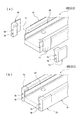
上述した第三の実施形態では、軌道レール311の縦断面略U字形の底面側であって、その長手方向に適宜間隔をおいて複数形成されるボルト取付孔311bに対して、本発明を適用した場合の形態例を示した。この第三の実施形態については、さらに別の変形形態を適用することが可能である。そこで、図15および図16を用いることで、第四の実施形態に係る運動案内装置を説明する。ここで、図15は、第四の実施形態に係る運動案内装置に用いられる軌道レールを説明するための図であり、図中の分図(a)は組み立て前の軌道レールの底面側を示す分解斜視図であり、分図(b)は組み立て後の軌道レールの底面側を示す斜視図であり、分図(c)は組み立て後の軌道レールの上面側を示す斜視図である。また、図16は、図15中の分図(c)におけるA−A断面を示す状態図に対して、締結手段であるボルトを設置した場合を示した図である。
[Fourth embodiment]
In the above-described third embodiment, the present invention is applied to a plurality of
第四の実施形態に係る運動案内装置に用いられる軌道レール411は、軌道レール411の縦断面略U字形の底面側であって、その長手方向に適宜間隔をおいて複数形成されるボルト取付孔411bの形成箇所の底面側に、略長円形をした溝形状部471を有している。この溝形状部471は、本発明に係る段落ち加工部としての機能を有する部位である。そして、この段落ち加工部としての溝形状部471には、図15中の分図(a)で示される金属材料からなる補強用取付部475が嵌め込まれる。この補強用取付部475には、中央部に大径の接合穴477が1つ形成されており、また、この大径の接合穴477の両側に、小径の接合穴478が2つ形成されている。段落ち加工部としての溝形状部471に対して補強用取付部475を嵌め込んだとき、軌道レール411に形成されたボルト取付孔411bと大径の接合穴477とが重畳して穴が導通した状態となる。また、軌道レール411に形成されたボルト取付孔411bの形成箇所の前後には、ボルト穴411cが形成されており、段落ち加工部としての溝形状部471に対して補強用取付部475を嵌め込んだとき、小径の接合穴478とボルト穴411cが重畳して穴が導通した状態となる。したがって、軌道レール411に形成されたボルト取付孔411bの形成箇所の前後に形成されたボルト穴411cを利用して、小径の接合穴478に対してボルト80を締結することで、補強用取付部475を軌道本体部431に対して強固に固定することが可能となる(図15中の分図(b)、分図(c)および図16参照)。
The
また、補強用取付部475に形成された大径の接合穴477と、軌道レール411に形成されたボルト取付孔411bとを利用して、図16に示すように、接合穴477とボルト取付孔411bとにボルト80を挿入して締結を行うことで、軌道レール411を固定対象物に対して強固に固定することが可能となる。また、第四の実施形態については、固定対象物に対する固定力は主として補強用取付部475に及ぼされ、FRRからなる軌道本体部431には固定力が実質的に及ばないので、ボルト80の締結力に基づく軌道レール411の歪みや形状変形が発生することが好適に防止され、運動案内装置の安定した取り付け状態を実現することが可能となる。
Further, using the large-diameter
以上、本発明の好適な実施形態について説明したが、本発明の技術的範囲は上記実施形態に記載の範囲には限定されない。上記実施形態には、多様な変更又は改良を加えることが可能である。 As mentioned above, although preferred embodiment of this invention was described, the technical scope of this invention is not limited to the range as described in the said embodiment. Various modifications or improvements can be added to the embodiment.
例えば、第一乃至第四の実施形態では、リニアモーションガイドとボールねじが組み合わされて一体構造となっている形式の運動案内装置10に対して、本発明を適用した場合について説明した。しかし、本発明は、あらゆる運動案内装置、例えば、工作機械などに用いられる転がり軸受全般や真空中で使用される無潤滑軸受、リニアガイドや直線案内装置、ボールスプライン装置、ボールねじ装置、ローラーリングなどに適用することが可能である。
For example, in the first to fourth embodiments, the case where the present invention is applied to the
また、上述した第一乃至第四の実施形態に係る運動案内装置10では、転動体としてのボール12が無限循環路20を無限に循環するように構成される場合について例示したが、転動体はローラとして構成されるものであっても良いし、さらに、転動体が無限に循環する形式のものだけではなく、有限タイプのものであっても良い。
Moreover, in the exercise |
さらに、上述した第一乃至第四の実施形態に係る運動案内装置は、軌道部材としての軌道レール11と移動部材13とが、転動体であるボール12を介して設置されている場合について例示した。しかし、本発明はこのような転がり案内動作を伴う装置ばかりでなく、例えば、ボールやローラなどの転動体を介さずに軌道部材と移動部材が設置されるような、すべり動作を伴う運動案内装置に対しても適用可能である。
Furthermore, the motion guide apparatus according to the first to fourth embodiments described above exemplifies a case where the
またさらに、上述した第一乃至第四の実施形態に係る運動案内装置10で用いたFRPについては、グラスファイバーなどの強化繊維を合成樹脂の中に入れて強度を向上させた材料であるが、本発明への適用に当たって、FRPの成型方法については限定されるものではない。すなわち、本発明が適用可能なFRPについては、型に強化繊維を敷き、硬化剤を混合した樹脂を脱泡しながら多重積層してゆくハンドレイアップ法やスプレイアップ法のほか、あらかじめ強化繊維と樹脂を混合したシート状のものを金型で圧縮成型するSMC(Sheet Molding Compounds)プレス法など、あらゆる成型方法によって製造されたものを用いることができる。
Furthermore, the FRP used in the
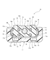
なお、上述した各実施形態に係る運動案内装置は、例えば、図17において示されるようなボールねじ装置として構成することが可能である。ここで、図17は、本発明に係る運動案内装置をボールねじ装置として構成した場合を例示する図である。すなわち、本発明に係る運動案内装置を、軌道部材としてのねじ軸511と、このねじ軸511に複数のボール512を介して相対回転可能に取り付けられる移動部材としてのナット513と、を備えたボールねじ装置510として構成し、ねじ軸511やナット513とボール512が接触する転動体転走面の近傍を金属材料によって形成し、その他の部分をFRPによって形成することが可能である。そして、取付部と、軌道本体部又は移動本体部とが、接合時において軌道本体部又は移動本体部を構成するFRPの強化繊維シートの積層方向に対して直交する方向に開口した接合穴をそれぞれ有し、当該接合穴に設置される接合手段を用いて接合可能であるように、このボールねじ装置を構成することも可能である。ボールねじ装置510をこのように構成することによって、外部部材との確実かつ高精度な取付状態の実現と、さらに、装置の軽量化をも実現する運動案内装置を提供することが可能となる。
In addition, the exercise | movement guide apparatus which concerns on each embodiment mentioned above can be comprised as a ball screw apparatus as shown, for example in FIG. Here, FIG. 17 is a diagram illustrating a case where the motion guide device according to the present invention is configured as a ball screw device. That is, the motion guide device according to the present invention includes a
その様な変更又は改良を加えた形態も本発明の技術的範囲に含まれ得ることが、特許請求の範囲の記載から明らかである。 It is apparent from the description of the scope of claims that embodiments with such changes or improvements can be included in the technical scope of the present invention.
10,200,300 運動案内装置、11,211,311,411 軌道レール、11a 転動体転走溝、11b,311b,411b ボルト取付孔、12 ボール、13,83 移動部材、13a 負荷転動体転走溝、13b 開口部、13c 上面、13d 雌ねじ、14 ねじ軸、15 負荷転動体転走路、16 戻し通路、17 方向転換路、18 蓋体、19 無負荷転動体転走路、20 無限循環路、21 スペーサ部材、30,40,41,42,44 転走部、31,331,431 軌道本体部、43 移動本体部、51,52 エンドハウジング、71,91 段落ち加工部、72,73,77,78,88,477,478 接合穴、75,95 取付部、76,86 取付孔、80 ボルト、80a 締結用ノックピン、81 ワッシャ、85 締結金具、95a 側面用取付部、95b 底面用取付部、375 金属カラー、376 取付孔、411c ボルト穴、471 溝形状部、475 補強用取付部、510 ボールねじ装置、511 ねじ軸、512 ボール、513 ナット、S 強化繊維シート。 10, 200, 300 motion guide device, 11, 211, 311, 411 track rail, 11a rolling element rolling groove, 11b, 311b, 411b bolt mounting hole, 12 balls, 13, 83 moving member, 13a loaded rolling element rolling Groove, 13b opening, 13c upper surface, 13d female thread, 14 screw shaft, 15 loaded rolling element rolling path, 16 return path, 17 direction changing path, 18 lid, 19 unloaded rolling element rolling path, 20 infinite circulation path, 21 Spacer member, 30, 40, 41, 42, 44 Rolling part, 31, 331, 431 Track body part, 43 Moving body part, 51, 52 End housing, 71, 91 Stepped part, 72, 73, 77, 78, 88, 477, 478 Joint hole, 75, 95 Mounting portion, 76, 86 Mounting hole, 80 bolt, 80a Fastening knock pin, 81 Washer, 85 Fastener, 95a Side mounting portion, 95b Bottom mounting portion, 375 Metal collar, 376 Mounting hole, 411c Bolt hole, 471 Groove shape portion, 475 Reinforcing mounting portion, 510 Ball screw device, 511 Screw shaft, 512 ball, 513 nut, S Reinforcing fiber sheet.
Claims (6)
前記軌道部材に複数の転動体を介して移動自在に取り付けられる移動部材と、
を備える運動案内装置であって、
前記軌道部材又は前記移動部材は、
前記複数の転動体と接触して転動体転走面を構成する金属材料から成る転走部と、
外部部材の取り付けのための取付孔が形成された金属材料から成る取付部と、
前記転走部および前記取付部と接合して前記軌道部材又は前記移動部材を形成するFRPから成る軌道本体部又は移動本体部と、
から構成され、
前記取付部と、前記軌道本体部又は前記移動本体部とは、接合時において前記軌道本体部又は前記移動本体部を構成するFRPの強化繊維シートの積層方向に対して直交する方向に開口した接合穴をそれぞれ有し、当該接合穴に設置される接合手段を用いて接合可能であることを特徴とする運動案内装置。 A track member;
A moving member that is movably attached to the track member via a plurality of rolling elements;
An exercise guidance device comprising:
The track member or the moving member is
A rolling part made of a metal material that contacts the plurality of rolling elements to form a rolling element rolling surface;
A mounting portion made of a metal material in which a mounting hole for mounting an external member is formed;
A track main body or a moving main body made of FRP which is joined to the rolling portion and the mounting portion to form the track member or the moving member;
Consisting of
The attachment portion and the track main body portion or the moving main body portion are joined in a direction orthogonal to the stacking direction of the FRP reinforcing fiber sheets constituting the track main body portion or the moving main body portion at the time of joining. A motion guide device having holes, and capable of being joined using joining means installed in the joining holes.
前記軌道部材に複数の転動体を介して移動自在に取り付けられる移動部材と、
を備える運動案内装置であって、
前記軌道部材又は前記移動部材は、
前記複数の転動体と接触して転動体転走面を構成する金属材料から成る転走部と、
外部部材の取り付けのための取付孔が形成された金属材料から成る取付部と、
前記転走部および前記取付部と接合して前記軌道部材又は前記移動部材を形成するFRPから成る軌道本体部又は移動本体部と、
から構成され、
前記取付部と、前記軌道本体部又は前記移動本体部とは、接合時において前記軌道本体部又は前記移動本体部を構成するFRPの強化繊維シートの積層方向に対して平行方向に拡がる接合面をそれぞれ有し、当該接合面に付与される接合手段を用いて接合可能であることを特徴とする運動案内装置。 A track member;
A moving member that is movably attached to the track member via a plurality of rolling elements;
An exercise guidance device comprising:
The track member or the moving member is
A rolling part made of a metal material that contacts the plurality of rolling elements to form a rolling element rolling surface;
A mounting portion made of a metal material in which a mounting hole for mounting an external member is formed;
A track main body or a moving main body made of FRP which is joined to the rolling portion and the mounting portion to form the track member or the moving member;
Consisting of
The attachment portion and the track main body portion or the moving main body portion have a joint surface that extends in a direction parallel to the stacking direction of the reinforcing fiber sheets of FRP constituting the track main body portion or the moving main body portion at the time of joining. A motion guide device characterized in that each of the motion guide devices can be joined using joining means provided on the joining surface.
前記軌道本体部又は前記移動本体部には、前記取付部が接合される箇所に対して前記取付部の形状に沿った段落ち加工部が形成されていることを特徴とする運動案内装置。 The motion guide apparatus according to claim 1 or 2,
The motion guide device according to claim 1, wherein a stepped portion is formed along the shape of the mounting portion at a position where the mounting portion is joined to the track main body portion or the moving main body portion.
前記接合手段は、ボルト、リベット又は接着剤のいずれか1つ若しくはこれらの組み合わせであることを特徴とする運動案内装置。 In the exercise | movement guide apparatus of any one of Claims 1-3,
The motion guiding device is characterized in that the joining means is any one of bolts, rivets, adhesives, or a combination thereof.
前記軌道部材は、断面略U字形をした部材として構成されており、
前記接合穴は、断面略U字形の底面側を向く第一の方向と、断面略U字形の左右面側を向くとともに前記第一の方向に直交する第二の方向と、の少なくとも二方向に向けて開口するように複数形成されることを特徴とする運動案内装置。 The motion guide device according to claim 1,
The track member is configured as a member having a substantially U-shaped cross section,
The joint hole is in at least two directions: a first direction facing the bottom surface side of the substantially U-shaped cross section and a second direction facing the left and right surface sides of the substantially U-shaped cross section and orthogonal to the first direction. A motion guide device, wherein a plurality of the guide devices are formed so as to open.
Priority Applications (8)
| Application Number | Priority Date | Filing Date | Title |
|---|---|---|---|
| DE112016005460.2T DE112016005460T5 (en) | 2015-11-30 | 2016-11-22 | Motion guide device and actuator |
| PCT/JP2016/004944 WO2017094239A1 (en) | 2015-11-30 | 2016-11-22 | Motion guidance device and actuator |
| US15/774,693 US10415640B2 (en) | 2015-11-30 | 2016-11-22 | Motion guide device and actuator |
| CN201911363397.XA CN110985540B (en) | 2015-11-30 | 2016-11-22 | Motion guide device and actuator |
| CN201680060185.2A CN108138846B (en) | 2015-11-30 | 2016-11-22 | Motion guide device and actuator |
| TW109125843A TWI732641B (en) | 2015-11-30 | 2016-11-25 | Motion guiding device and actuator |
| TW105138833A TWI699490B (en) | 2015-11-30 | 2016-11-25 | Motion guiding device and actuator |
| US16/533,070 US10718378B2 (en) | 2015-11-30 | 2019-08-06 | Motion guide device and actuator |
Applications Claiming Priority (2)
| Application Number | Priority Date | Filing Date | Title |
|---|---|---|---|
| JP2015233142 | 2015-11-30 | ||
| JP2015233142 | 2015-11-30 |
Related Child Applications (1)
| Application Number | Title | Priority Date | Filing Date |
|---|---|---|---|
| JP2017174594A Division JP6496374B2 (en) | 2015-11-30 | 2017-09-12 | Motion guide device and actuator |
Publications (2)
| Publication Number | Publication Date |
|---|---|
| JP2017106622A true JP2017106622A (en) | 2017-06-15 |
| JP6211669B2 JP6211669B2 (en) | 2017-10-11 |
Family
ID=59060593
Family Applications (2)
| Application Number | Title | Priority Date | Filing Date |
|---|---|---|---|
| JP2016222882A Active JP6211669B2 (en) | 2015-11-30 | 2016-11-16 | Motion guide device and actuator |
| JP2017174594A Active JP6496374B2 (en) | 2015-11-30 | 2017-09-12 | Motion guide device and actuator |
Family Applications After (1)
| Application Number | Title | Priority Date | Filing Date |
|---|---|---|---|
| JP2017174594A Active JP6496374B2 (en) | 2015-11-30 | 2017-09-12 | Motion guide device and actuator |
Country Status (5)
| Country | Link |
|---|---|
| US (2) | US10415640B2 (en) |
| JP (2) | JP6211669B2 (en) |
| CN (2) | CN108138846B (en) |
| DE (1) | DE112016005460T5 (en) |
| TW (2) | TWI699490B (en) |
Cited By (3)
| Publication number | Priority date | Publication date | Assignee | Title |
|---|---|---|---|---|
| CN108478231A (en) * | 2018-05-04 | 2018-09-04 | 合肥美亚光电技术股份有限公司 | Guide frame and oral cavity CBCT devices for oral cavity CBCT devices |
| CN110957888A (en) * | 2018-09-27 | 2020-04-03 | 东佑达自动化科技股份有限公司 | Sliding table device |
| WO2020149268A1 (en) * | 2019-01-18 | 2020-07-23 | 株式会社牧野フライス製作所 | Feeding device of machine tool |
Families Citing this family (3)
| Publication number | Priority date | Publication date | Assignee | Title |
|---|---|---|---|---|
| JP6604488B2 (en) * | 2018-02-09 | 2019-11-13 | Thk株式会社 | Linear motion guide device and method of manufacturing linear motion guide device |
| CN113195913B (en) * | 2018-12-12 | 2023-02-21 | 美津浓科技股份有限公司 | Slide rail unit and method for manufacturing slide rail unit |
| TWI769806B (en) * | 2021-05-03 | 2022-07-01 | 東佑達自動化科技股份有限公司 | Compound screw slide table |
Citations (9)
| Publication number | Priority date | Publication date | Assignee | Title |
|---|---|---|---|---|
| JPS6078108A (en) * | 1983-10-06 | 1985-05-02 | Mitsubishi Rayon Co Ltd | Carbon fiber reinforced plastic slider |
| JPS6375475U (en) * | 1986-11-05 | 1988-05-19 | ||
| JPH035100U (en) * | 1989-05-19 | 1991-01-18 | ||
| JP2003206926A (en) * | 2002-01-11 | 2003-07-25 | Nsk Ltd | One shaft actuator |
| JP2004312983A (en) * | 2003-03-25 | 2004-11-04 | Thk Co Ltd | Linear motor actuator |
| JP2005059596A (en) * | 2003-08-08 | 2005-03-10 | Stork Fokker Aesp Bv | Method for forming stepped laminate |
| JP2005282677A (en) * | 2004-03-29 | 2005-10-13 | Nsk Ltd | Linear guide device |
| JP4813373B2 (en) * | 2004-12-21 | 2011-11-09 | Thk株式会社 | Exercise guidance device |
| US20130129409A1 (en) * | 2011-11-23 | 2013-05-23 | Hyundai Motor Company | Device and method for joining a composite and metallic material |
Family Cites Families (19)
| Publication number | Priority date | Publication date | Assignee | Title |
|---|---|---|---|---|
| GB1005360A (en) * | 1961-12-01 | 1965-09-22 | Rothe Erde Eisenwerk | Rolling contact bearing |
| US4417771A (en) * | 1982-06-22 | 1983-11-29 | Hiroshi Teramachi | Linear ball bearing unit |
| JP3687755B2 (en) * | 1995-03-15 | 2005-08-24 | 日本精工株式会社 | Polymer-lubricated linear guide device containing lubricant |
| JPH08298193A (en) | 1995-04-27 | 1996-11-12 | San Electron Kogyo Kk | Stabilizer for fluorescent lamp |
| JP4026864B2 (en) * | 1995-08-02 | 2007-12-26 | Thk株式会社 | Rolling guide device |
| JP3969247B2 (en) * | 2001-11-06 | 2007-09-05 | 株式会社デンソー | Fuel injection valve |
| JP4071975B2 (en) * | 2002-02-26 | 2008-04-02 | 日本トムソン株式会社 | Linear motion guidance unit |
| US8764302B2 (en) * | 2002-03-26 | 2014-07-01 | Kureha Gosen Co., Ltd | Tape-shaped molding and belt for ball chain |
| JP4202051B2 (en) * | 2002-05-31 | 2008-12-24 | Thk株式会社 | Lubricant supply device, guide device equipped with the same, and lubricating grease used therefor |
| JP2005106284A (en) | 2003-09-09 | 2005-04-21 | Smc Corp | Actuator |
| DE102004043606A1 (en) | 2003-09-09 | 2005-04-14 | Smc K.K. | actuator |
| US7229213B2 (en) | 2003-10-07 | 2007-06-12 | Nsk, Ltd. | Linear guide device |
| EP1830079A4 (en) * | 2004-11-22 | 2011-08-31 | Thk Co Ltd | Movement guiding device for vacuum environment |
| JPWO2007013422A1 (en) * | 2005-07-27 | 2009-02-05 | Thk株式会社 | Method for manufacturing motion guide device, and motion guide device manufactured using this method |
| EP1918597A4 (en) * | 2005-08-25 | 2011-10-26 | Thk Co Ltd | Movement guiding device |
| CN101641526B (en) * | 2007-03-29 | 2013-01-09 | Thk株式会社 | Motion guide device and method of producing the same |
| JP2008298193A (en) | 2007-05-31 | 2008-12-11 | Nsk Ltd | Uniaxial actuator |
| JP6185752B2 (en) * | 2012-05-11 | 2017-08-23 | Thk株式会社 | Exercise guidance device |
| DE102013203771A1 (en) * | 2013-03-06 | 2014-09-11 | Robert Bosch Gmbh | Linear rolling bearing with glued Wälzflächenteil |
-
2016
- 2016-11-16 JP JP2016222882A patent/JP6211669B2/en active Active
- 2016-11-22 DE DE112016005460.2T patent/DE112016005460T5/en active Pending
- 2016-11-22 CN CN201680060185.2A patent/CN108138846B/en active Active
- 2016-11-22 CN CN201911363397.XA patent/CN110985540B/en active Active
- 2016-11-22 US US15/774,693 patent/US10415640B2/en active Active
- 2016-11-25 TW TW105138833A patent/TWI699490B/en active
- 2016-11-25 TW TW109125843A patent/TWI732641B/en active
-
2017
- 2017-09-12 JP JP2017174594A patent/JP6496374B2/en active Active
-
2019
- 2019-08-06 US US16/533,070 patent/US10718378B2/en active Active
Patent Citations (9)
| Publication number | Priority date | Publication date | Assignee | Title |
|---|---|---|---|---|
| JPS6078108A (en) * | 1983-10-06 | 1985-05-02 | Mitsubishi Rayon Co Ltd | Carbon fiber reinforced plastic slider |
| JPS6375475U (en) * | 1986-11-05 | 1988-05-19 | ||
| JPH035100U (en) * | 1989-05-19 | 1991-01-18 | ||
| JP2003206926A (en) * | 2002-01-11 | 2003-07-25 | Nsk Ltd | One shaft actuator |
| JP2004312983A (en) * | 2003-03-25 | 2004-11-04 | Thk Co Ltd | Linear motor actuator |
| JP2005059596A (en) * | 2003-08-08 | 2005-03-10 | Stork Fokker Aesp Bv | Method for forming stepped laminate |
| JP2005282677A (en) * | 2004-03-29 | 2005-10-13 | Nsk Ltd | Linear guide device |
| JP4813373B2 (en) * | 2004-12-21 | 2011-11-09 | Thk株式会社 | Exercise guidance device |
| US20130129409A1 (en) * | 2011-11-23 | 2013-05-23 | Hyundai Motor Company | Device and method for joining a composite and metallic material |
Cited By (7)
| Publication number | Priority date | Publication date | Assignee | Title |
|---|---|---|---|---|
| CN108478231A (en) * | 2018-05-04 | 2018-09-04 | 合肥美亚光电技术股份有限公司 | Guide frame and oral cavity CBCT devices for oral cavity CBCT devices |
| CN108478231B (en) * | 2018-05-04 | 2024-02-02 | 合肥美亚光电技术股份有限公司 | Guiding structure for oral cavity CBCT device and oral cavity CBCT device |
| CN110957888A (en) * | 2018-09-27 | 2020-04-03 | 东佑达自动化科技股份有限公司 | Sliding table device |
| CN110957888B (en) * | 2018-09-27 | 2022-05-17 | 东佑达自动化科技股份有限公司 | Sliding table device |
| WO2020149268A1 (en) * | 2019-01-18 | 2020-07-23 | 株式会社牧野フライス製作所 | Feeding device of machine tool |
| JP2020116648A (en) * | 2019-01-18 | 2020-08-06 | 株式会社牧野フライス製作所 | Feeding device of machine tool |
| JP7113431B2 (en) | 2019-01-18 | 2022-08-05 | 株式会社牧野フライス製作所 | machine tool feeder |
Also Published As
| Publication number | Publication date |
|---|---|
| US20190360570A1 (en) | 2019-11-28 |
| US10415640B2 (en) | 2019-09-17 |
| CN108138846A (en) | 2018-06-08 |
| DE112016005460T5 (en) | 2018-08-16 |
| JP6211669B2 (en) | 2017-10-11 |
| US20180355959A1 (en) | 2018-12-13 |
| US10718378B2 (en) | 2020-07-21 |
| JP6496374B2 (en) | 2019-04-03 |
| TWI699490B (en) | 2020-07-21 |
| CN110985540B (en) | 2021-07-09 |
| CN108138846B (en) | 2020-01-21 |
| TW201728840A (en) | 2017-08-16 |
| TWI732641B (en) | 2021-07-01 |
| TW202043639A (en) | 2020-12-01 |
| CN110985540A (en) | 2020-04-10 |
| JP2017215049A (en) | 2017-12-07 |
Similar Documents
| Publication | Publication Date | Title |
|---|---|---|
| JP6496374B2 (en) | Motion guide device and actuator | |
| JP4813373B2 (en) | Exercise guidance device | |
| US11346435B2 (en) | Reducer of electric power steering apparatus | |
| CN104802667A (en) | Automobile sliding rail assembly and motor bracket thereof | |
| KR20190092607A (en) | Motion guiding device | |
| WO2017094239A1 (en) | Motion guidance device and actuator | |
| JP5648727B1 (en) | Ball screw | |
| EP1830106A1 (en) | Ball screw device | |
| US20150369277A1 (en) | Universal Joint Jaw, Assembly for a Double Universal Ball Joint and Machining Method | |
| US20030215167A1 (en) | Linear motion guide unit | |
| US10271470B2 (en) | Linear motion device and electronic component mounting apparatus | |
| JP3173955U (en) | Electric linear actuator | |
| JPH05306713A (en) | Direct acting guide unit | |
| JP2018201026A (en) | Direct-acting device and electronic component-mounted apparatus | |
| JP6507686B2 (en) | Bearing ring | |
| KR20180076239A (en) | Rivet and methode for joining of pannel using the same | |
| JP4657936B2 (en) | Ball screw | |
| JP2011052724A (en) | Rolling element screw device | |
| JP2023155744A (en) | Motion guide device | |
| KR20170133192A (en) | Non-screw type linear slide rail |
Legal Events
| Date | Code | Title | Description |
|---|---|---|---|
| A621 | Written request for application examination |
Free format text: JAPANESE INTERMEDIATE CODE: A621 Effective date: 20170420 |
|
| A871 | Explanation of circumstances concerning accelerated examination |
Free format text: JAPANESE INTERMEDIATE CODE: A871 Effective date: 20170420 |
|
| A975 | Report on accelerated examination |
Free format text: JAPANESE INTERMEDIATE CODE: A971005 Effective date: 20170519 |
|
| A131 | Notification of reasons for refusal |
Free format text: JAPANESE INTERMEDIATE CODE: A131 Effective date: 20170530 |
|
| A521 | Request for written amendment filed |
Free format text: JAPANESE INTERMEDIATE CODE: A523 Effective date: 20170705 |
|
| TRDD | Decision of grant or rejection written | ||
| A01 | Written decision to grant a patent or to grant a registration (utility model) |
Free format text: JAPANESE INTERMEDIATE CODE: A01 Effective date: 20170905 |
|
| A61 | First payment of annual fees (during grant procedure) |
Free format text: JAPANESE INTERMEDIATE CODE: A61 Effective date: 20170913 |
|
| R150 | Certificate of patent or registration of utility model |
Ref document number: 6211669 Country of ref document: JP Free format text: JAPANESE INTERMEDIATE CODE: R150 |
|
| R250 | Receipt of annual fees |
Free format text: JAPANESE INTERMEDIATE CODE: R250 |
|
| R250 | Receipt of annual fees |
Free format text: JAPANESE INTERMEDIATE CODE: R250 |
|
| R250 | Receipt of annual fees |
Free format text: JAPANESE INTERMEDIATE CODE: R250 |
|
| R250 | Receipt of annual fees |
Free format text: JAPANESE INTERMEDIATE CODE: R250 |