JP2017106507A - Support device - Google Patents
Support device Download PDFInfo
- Publication number
- JP2017106507A JP2017106507A JP2015239385A JP2015239385A JP2017106507A JP 2017106507 A JP2017106507 A JP 2017106507A JP 2015239385 A JP2015239385 A JP 2015239385A JP 2015239385 A JP2015239385 A JP 2015239385A JP 2017106507 A JP2017106507 A JP 2017106507A
- Authority
- JP
- Japan
- Prior art keywords
- band
- support device
- flange
- pipe
- support
- Prior art date
- Legal status (The legal status is an assumption and is not a legal conclusion. Google has not performed a legal analysis and makes no representation as to the accuracy of the status listed.)
- Pending
Links
Images


Abstract
Description
本発明は、構造物内に配置された配管系を支持する支持装置に関する。 The present invention relates to a support device that supports a piping system disposed in a structure.
化学プラント、発電設備等の構造物内に配置された配管系は、地震や熱等による変位を抑制するよう支持装置により支持及び拘束されている。 Piping systems arranged in structures such as chemical plants and power generation facilities are supported and restrained by a supporting device so as to suppress displacement due to earthquakes, heat, or the like.
この種の支持装置として、枠体状構造物で拘束したバンドラグで外周面を締めつけることで配管を支持及び拘束するものがある(特許文献1等を参照)。
As this type of support device, there is a device that supports and restrains piping by tightening an outer peripheral surface with a band lug restrained by a frame-like structure (see
特許文献1では、配管の外周面とバンドラグの内周面との接触面に生じる摩擦力により配管のその中心軸方向への変位を拘束している。しかしながら、地震や熱等により配管に作用する中心軸方向の力が前述の摩擦力より大きくなると、配管の軸方向への変位を拘束し切れない可能性がある。
In
本発明は、上記に鑑みてなされたもので、配管の拘束力を向上させることができる支持装置を提供することを目的とする。 The present invention has been made in view of the above, and an object of the present invention is to provide a support device capable of improving the restraining force of piping.
配管を支持体に連結して支持する支持装置において、前記配管のフランジの少なくとも一部を収容する収容部を有する把持部材と、前記支持体に接続するとともに前記把持部材を囲むように設けられ、前記把持部材を前記支持体に対し固定する固定部材とを備えることを特徴とする。 In a support device for connecting and supporting a pipe to a support, a gripping member having a housing portion that houses at least a part of the flange of the pipe, and being provided so as to be connected to the support and surround the gripping member, And a fixing member that fixes the gripping member to the support.
本発明によれば、配管の拘束力を向上させることができる支持装置を提供することができる。 ADVANTAGE OF THE INVENTION According to this invention, the support apparatus which can improve the restraint force of piping can be provided.
<第1実施形態>
(構成)
1.支持装置
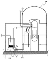
図1は、本実施形態に係る支持装置の適用例を示す図である。図1に示すように、本実施形態に係る支持装置10は、配管のフランジに設けられ、配管を支持物に連結して支持するものである。支持物は、配管を連結して支持する基礎となるものであり、例えば、配管付近にある床面、壁面等の固定物である。本実施形態では、配管を原子力発電設備の原子炉格納施設100内に配置された配管1(1a,1b)、支持物を原子炉格納施設100の床面11とした場合を例示する。
<First Embodiment>
(Constitution)
1. Support Device FIG. 1 is a diagram illustrating an application example of a support device according to the present embodiment. As shown in FIG. 1, the
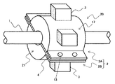
図2は、図1のII−II線の矢視断面図である。図2に示すように、本実施形態に係る支持装置10は、バンド2、ラグ3、固定部材6及び拘束部材7を備えている。
2 is a cross-sectional view taken along line II-II in FIG. As shown in FIG. 2, the
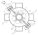
1−1.バンド
図3は、本実施形態に係るバンドの概略構成図である。図3に示すように、本実施形態に係るバンド(把持部材)2は、第1バンド部2A及び第2バンド部2Bを備えている。本実施形態では、第1,2バンド部2A,2Bは、半割れ形状のケーシングである。第1,2バンド部2A,2Bは、それぞれ本体部20及び平板部4を備えている。以下、第2バンド部2Bについて説明するが、第1バンド部2Aも同様の構成である。
1-1. Band FIG. 3 is a schematic configuration diagram of a band according to the present embodiment. As shown in FIG. 3, the band (gripping member) 2 according to this embodiment includes a
本体部20は、外周壁部17及び端壁部21を含んでいる。
The
外周壁部17は、本体部20の周胴部であって板材を半円弧状に曲げたトラフ状の形状をしており、配管1にバンド2を装着した時(以下、単に「装着時」と記載する)に配管1のフランジ5の外周を覆う。装着時には、外周壁部17の内周面23がフランジ5の外周面に対向する(内周面23がフランジ5に接触する構成も間隙を介して対向する構成も含む)。
The outer
端壁部21は、配管1の中心軸が伸びる方向(以下、単に「軸方向」と記載する)において外周壁部17の両端をカバーする半円板状の部分であり、装着時にフランジ5を挟んで軸方向の両側に位置する。端壁部21の外周部は、外周壁部17の軸方向の端部に繋がって一体になっている。装着時には、端壁部21の内周面22は配管1の外周面に対向する(内周面22が配管1に接触する構成も間隙を介して対向する構成も含む)。この端壁部21における装着時にフランジ5に対して軸方向に対向する壁面(以下、「フランジ対向面24」と記載する)は、配管1の径方向に延びる。フランジ対向面24は円錐面や曲面でも良いが、本実施形態では配管1に直交する平面としてある。端壁部21の内周面22は、外周壁部17の内周面23よりも小径である。
The
外周壁部17と端壁部21とでこのように構成したことにより、第2バンド部2Bには、装着時に配管1のフランジ5を収容する収容部12が形成されている。収容部12は、外周壁部17の内周面23と端壁部21のフランジ対向面24とで画定された有底の円筒状(厳密には半円筒状)の空間である。端壁部21の内周面22の口径によりフランジ5の一部しか収容部12に収容されない構成となる場合もあるが、本実施形態の収容部12は、実質的にフランジ5の全体を収容する構成としてある。本実施形態の収容部12は、フランジ5とともにフランジ5を締結するボルト18を収容している。つまり、本実施形態では、収容部12の軸方向の幅がフランジ5を締結するボルト18のフランジ面からの突出長さも含めた寸法に設定されており、フランジ対向面24とボルト18の端部とが対向している(フランジ対向面24がボルト18の端部に接触する構成も間隙を介して対向する構成も含む)。
Since the outer
平板部4は、軸方向から見て、本体部20の周方向の両端部に取り付けられており、本体部20の外周壁部17から本体部20の径方向外方に延在している。平板部4には、複数(本実施形態では2つ)のボルト穴13が軸方向に並べて形成されている。第1バンド部2Aのボルト穴13と第2バンド部2Bのボルト穴13とは、装着時に互いに対向するように設けられている。
The flat plate portion 4 is attached to both end portions in the circumferential direction of the
1−2.ラグ
ラグ(突出部)3は、四角形状(本実施形態では、直方体状)に形成されたブロックであり、第2バンド部2Bの本体部20の外周壁部17から第2バンド部2Bの径方向外方に突出するように設けられている。ラグ3は、軸方向から見て、本体部20の外周壁部17に本体部20の周方向に間隔を空けて複数(本実施形態では2つ)配置されている(図2を参照)。本実施形態では、ラグ3は、溶接等により外周壁部17に取り付けられている。
1-2. The lug lug (projecting part) 3 is a block formed in a quadrangular shape (in the present embodiment, a rectangular parallelepiped shape), and the diameter of the
1−3.固定部材
図2に示すように、固定部材6は、床面11に接続するとともにバンド2を囲むように設けられており、バンド2を床面11に対し固定している。固定部材6は、支持部材18(18a〜18d)を備えている。支持部材18a,18bは、例えば金物(不図示)を介して原子炉格納施設100の床面11に取り付けられており、床面11から上方向に立設している。支持部材18cは、バンド2と床面11との間に位置するように支持部材18a,18bに取り付けられており、バンド2の下方を覆っている。支持部材18dは、バンド2を挟んで支持部材18cと対向するように支持部材18a,18bに取り付けられており、バンド2の上方を覆っている。
1-3. Fixing Member As shown in FIG. 2, the
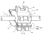
1−4.拘束部材
図4は、ラグと拘束部材が係合した状態を示す図である。図2,4に示すように、拘束部材7(7a〜7d)は、支持部材18a〜18dの内面20(20a〜20d)に取り付けられている。本実施形態では、拘束部材7は、ラグ3が挿入可能な凹部29を有する門型(コの字型)に形成されており、ラグ3が凹部29に配管1の径方向に挿し込まれることで、ラグ3と拘束部材7が互いに係合する。本実施形態では、拘束部材7は、弾性体(ゴムやバネ等)で形成されている。
1-4. FIG. 4 is a diagram illustrating a state where the lug and the restraining member are engaged. As shown in FIGS. 2 and 4, the restraining member 7 (7 a to 7 d) is attached to the inner surface 20 (20 a to 20 d) of the
(取り付け方法)
図5は本実施形態に係るバンドを配管に装着した状態を示す図、図6は本実施形態に係るバンドを配管に固定した状態を示す図である。以下、本実施形態に係る支持装置10を配管1に取り付ける方法について説明する。
(installation method)
FIG. 5 is a diagram illustrating a state in which the band according to the present embodiment is attached to the pipe, and FIG. 6 is a diagram illustrating a state in which the band according to the present embodiment is fixed to the pipe. Hereinafter, a method for attaching the
・ステップ1
図5に示すように、第1バンド部2A及び第2バンド部2Bを配管1を挟むように配管1に向かって押し込んで、第1,2バンド部2A,2Bを配管1に装着する。このとき、第1,2バンド部2A,2Bの収容部12には、フランジ5とフランジ5を締結するボルト18とが収容される(図6を参照)。
・
As shown in FIG. 5, the first and
・ステップ2
第1,2バンド部2A,2Bを配管1に装着した後、図6に示すように、第1,2バンド部2A,2Bをボルト19で締結する。これにより、配管1に対しバンド2が固定される。
・
After the first and
なお、原子炉格納施設の耐震強度を強化して安全性を向上させるべく、既設の配管に支持装置を取り付ける場合がある。既設の配管に支持装置を取り付ける方法として、配管に溶接によりバンドを装着する方法がある。しかし、この方法では、既設の配管を取り外す必要があるため作業が大規模になる可能性がある。加えて、一般的に、配管の内側には、内部を流れる海水により錆が発生することを抑止するため、ゴムやポリエチレンの膜が張り付けられている(ライニング)が、上述した方法では、溶接による熱の影響で膜が溶けてしまう可能性がある。これに対し、本実施形態では、第1バンド部2A及び第2バンド部2Bを配管1を挟むように配管1に向かって押し込んで、第1,2バンド部2A,2Bを配管1に装着しているので、配管に溶接によりバンドを装着する方法に比べて作業規模を小さくすることができ、加えて、配管の内側に形成された膜が溶けることを抑止することもできる。
In order to enhance the seismic strength of the containment facility and improve safety, a support device may be attached to existing piping. As a method of attaching a support device to an existing pipe, there is a method of attaching a band to the pipe by welding. However, in this method, since it is necessary to remove the existing piping, the work may become large-scale. In addition, in general, a rubber or polyethylene film is attached to the inside of the pipe to prevent rust from being generated by the seawater flowing inside (lining). The film may melt under the influence of heat. On the other hand, in the present embodiment, the
・ステップ3
配管1に対しバンド2を固定した後、バンド2のラグ3が拘束部材7a,7bと係合するように、支持部材18a,18bを床面11に取り付ける(図2を参照)。
・
After fixing the
・ステップ4
支持部材18a,18bを床面11に取り付けた後、バンド2のラグ3が拘束部材7cと係合するように、支持部材18cを支持部材18a,18bに取り付ける(図2を参照)。
・ Step 4
After attaching the supporting
・ステップ5
支持部材18cを支持部材18a,18bに取り付けた後、バンド2のラグ3が拘束部材7dと係合するように、支持部材18dを支持部材18a,18bに取り付ける(図2を参照)。上述した手順により、配管1に支持装置10を取り付けることができる。
・
After attaching the
(効果)
本実施形態では、配管1のフランジ5をバンド2の収容部12に収容して配管1を床面11に固定しているので、フランジ5の軸方向の変位を収容部12のフランジ対向面24で受け止めて拘束することができる。従って、配管の外周面とバンドの内周面との接触面に生じる摩擦力で配管の中心軸方向への変位を拘束する場合に比べて、配管1の拘束力を向上させることができる。
(effect)
In the present embodiment, since the
また、本実施形態では、バンド2の外周壁部17から突出するラグ3と固定部材6の内面に設けられた拘束部材7とを係合させて配管1を固定部材6に固定しているので、ラグ3の配管1の中心軸方向の変位を拘束部材7で拘束することができ、その分、配管1の拘束力をより向上させることができる。
In the present embodiment, since the
<第2実施形態>
(構成)
図7は本実施形態に係るバンドを配管に装着した状態を示す図、図8はラグと拘束部材が係合した状態を示す図である。図7,8において、上記第1実施形態と同等の部分には同一の符号を付し、適宜説明を省略する。
Second Embodiment
(Constitution)
FIG. 7 is a view showing a state in which the band according to the present embodiment is attached to the pipe, and FIG. 8 is a view showing a state in which the lug and the restraining member are engaged. 7 and 8, the same parts as those in the first embodiment are denoted by the same reference numerals, and description thereof will be omitted as appropriate.
本実施形態に係る支持装置は、ラグ及び拘束部材の形状が異なる点で第1実施形態に係る支持装置10と異なる。その他の構成は、第1実施形態に係る支持装置10と同様である。
The support device according to the present embodiment is different from the
図7,8に示すように、本実施形態に係るラグ25は、後述の拘束部材27が挿入可能な凹部26を有する門型(コの字型)に形成されている。その他の構成は、第1実施形態に係るラグ3と同様である。
As shown in FIGS. 7 and 8, the
図8に示すように、本実施形態に係る拘束部材27は、四角形状に形成されたブロックである。本実施形態では、拘束部材27がラグ25の凹部26に配管1の径方向に挿し込まれることで、ラグ25と拘束部材27が互いに係合する。
As shown in FIG. 8, the restraining
本実施形態のように、ラグ25を門型、拘束部材27を四角形状に形成した場合でも、第1実施形態と同様の効果を得ることができる。
Even when the
<第3実施形態>
(構成)
図9は、本実施形態に係るバンドを配管に固定した状態を示す図である。図9において、上記第1実施形態と同等の部分には同一の符号を付し、適宜説明を省略する。
<Third Embodiment>
(Constitution)
FIG. 9 is a diagram illustrating a state in which the band according to the present embodiment is fixed to the pipe. In FIG. 9, parts that are the same as in the first embodiment are given the same reference numerals, and descriptions thereof are omitted as appropriate.
本実施形態に係る支持装置は、バンドの形状が異なる点で第1実施形態に係る支持装置10と異なる。その他の構成は、第1実施形態に係る支持装置10と同様である。
The support device according to the present embodiment is different from the
図9に示すように、本実施形態に係るバンド202の端壁部221は、軸方向から見て、配管1のフランジ5を締結するボルト18よりも配管1の径方向外方でフランジ5と対向するように形成されている。つまり、本実施形態では、バンド202の収容部は、フランジ5の外縁部を収容している。その他の構成は、第1実施形態に係るバンド2と同様である。
As shown in FIG. 9, the
本実施形態でも、第1実施形態と同様の効果を得ることができる。加えて、本実施形態では、以下の効果が得られる。 Also in this embodiment, the same effect as the first embodiment can be obtained. In addition, in the present embodiment, the following effects can be obtained.
本実施形態では、バンド202の端壁部221をフランジ5を締結するボルト18よりも外側でフランジ5と対向するように形成しているので、バンド202の外側からボルト18を見ることができる。従って、バンド2を配管1から取り外すことなくボルト18の緩みその他の状態を点検することができ、万一ボルト18が緩んでいる場合には、配管1に対してバンド2を固定したままボルト18締めることができる。
In this embodiment, the
また、本実施形態では、バンド202の端壁部221をフランジ5を締結するボルト18を逃がすように形成している。そのため、収容部12の軸方向の幅をボルト18のフランジ面からの突出長さも含めた寸法に設定する必要がなく、その分、端壁部221の軸方向の厚みを第1実施形態よりも大きく確保することができる。
In the present embodiment, the
また、本実施形態では、バンド202の端壁部221にフランジ5を当ててフランジ5を拘束するため、端壁部にフランジ5を締結するボルト18の端部を当ててフランジ5を拘束する構成に比べて、端壁部のフランジ5に対向する面に発生する面圧を下げることができる。
Moreover, in this embodiment, in order to restrain the
<第4実施形態>
(構成)
図10は、本実施形態に係るバンドを配管に固定した状態を示す図である。図10において、上記第1実施形態と同等の部分には同一の符号を付し、適宜説明を省略する。
<Fourth embodiment>
(Constitution)
FIG. 10 is a diagram illustrating a state in which the band according to the present embodiment is fixed to the pipe. In FIG. 10, parts that are the same as in the first embodiment are given the same reference numerals, and descriptions thereof are omitted as appropriate.
本実施形態に係る支持装置は、バンドの形状が異なる点で第1実施形態に係る支持装置10と異なる。その他の構成は、第1実施形態に係る支持装置10と同様である。
The support device according to the present embodiment is different from the
図10に示すように、本実施形態では、バンド302の端壁部321にフランジ5を締結するボルト18と干渉しないようにスリット28が形成されている。スリット28は、軸方向から見て、端壁部321の内周部から配管1の径方向外方に向かって延在して設けられている。その他の構成は、第1実施形態に係るバンド2と同様である。
As shown in FIG. 10, in this embodiment, the
本実施形態のように、バンド302の端壁部321にフランジ5を締結するボルト18と干渉しないようにスリット28を形成した場合にも、第3実施形態と同様の効果を得ることができる。
Even when the
<第5実施形態>
(構成)
図11は、本実施形態に係るバンドを配管に固定した状態を示す図である。図11において、上記第1実施形態と同等の部分には同一の符号を付し、適宜説明を省略する。
<Fifth Embodiment>
(Constitution)
FIG. 11 is a diagram illustrating a state in which the band according to the present embodiment is fixed to the pipe. In FIG. 11, parts that are the same as in the first embodiment are given the same reference numerals, and descriptions thereof are omitted as appropriate.
本実施形態に係る支持装置は、バンドの形状が異なる点で第1実施形態に係る支持装置10と異なる。その他の構成は、第1実施形態に係る支持装置10と同様である。
The support device according to the present embodiment is different from the
図11に示すように、本実施形態では、バンド402の端壁部421にフランジ5を締結するボルト18が貫通可能な貫通孔30が形成されている。本実施形態では、貫通孔30は、軸方向から見て、装着時にフランジ5に形成されたボルト18が挿入可能なボルト穴(不図示)に対向するように形成されている。本実施形態では、配管1に対してバンド402を固定した後、バンド402の貫通孔30にボルト18を挿入し、バンド402と配管1のフランジ5とを一体的に締結する。その他の構成は、第1実施形態に係るバンド2と同様である。
As shown in FIG. 11, in the present embodiment, a through
本実施形態のように、バンド402の端壁部421にフランジ5を締結するボルト18が貫通可能な貫通孔30を形成した場合にも、第3実施形態と同様の効果を得ることができる。
As in the present embodiment, even when the through
<その他>
本発明は上述した各実施形態に限定されるものではなく、様々な変形例が含まれる。例えば、上述した各実施形態は本発明を分かりやすく説明するために詳細に説明したものであり、必ずしも説明した全ての構成を備えるものに限定されるものではない。例えば、ある実施形態の構成の一部を他の実施形態の構成に置き換えることが可能であり、また、ある実施形態の構成に他の実施形態の構成を追加することも可能である。
<Others>
The present invention is not limited to the above-described embodiments, and includes various modifications. For example, each of the above-described embodiments has been described in detail for easy understanding of the present invention, and is not necessarily limited to one having all the configurations described. For example, a part of the configuration of one embodiment can be replaced with the configuration of another embodiment, and the configuration of another embodiment can be added to the configuration of one embodiment.
上述した各実施形態では、バンド2の外周壁面17から突出したラグ3と固定部材6の内面に取り付けられた拘束部材7とを互いに係合させて、バンド2を固定部材6を介して原子炉格納施設100の床面11に固定する構成を例示した。しかしながら、本発明の本質的効果は配管の拘束力を向上させることができる支持装置を提供することであり、この本質的効果を得る限りにおいては、必ずしも上述した構成に限定されない。例えば、バンド2の外周面と固定部材6の内面とを接続して、バンド2を原子炉格納施設100の床面11に固定する構成としても良い。
In each of the above-described embodiments, the
また、上述した各実施形態では、本発明を原子炉格納施設100内に配置された配管1に適用した場合を例示した。しかしながら、上述した本発明の本質的効果を得る限りにおいては、本発明の適用対象は、原子力発電設備の原子炉格納施設100内に配置された配管に限定されない。例えば、原子力発電設備の他の構成機器内に配置された配管、化学プラントの構成機器内に配置された配管等にも本発明を適用することができる。
Moreover, in each embodiment mentioned above, the case where this invention was applied to the
1 配管
11 床面(支持体)
10 支持装置
5 フランジ
12 収容部
2,102,202,302,402 バンド(把持部材)
6 固定部材
17 外周壁部
3 ラグ(突出部)
7 拘束部材
18 ボルト
28 スリット
30 貫通孔
1
DESCRIPTION OF
6 fixing
7 Restraining
Claims (7)
前記配管のフランジの少なくとも一部を収容する収容部を有する把持部材と、
前記支持体に接続するとともに前記把持部材を囲むように設けられ、前記把持部材を前記支持体に対し固定する固定部材と
を備えることを特徴とする支持装置。 In a support device that supports piping connected to a support,
A gripping member having an accommodating portion for accommodating at least a part of the flange of the pipe;
A support device comprising: a fixing member that is connected to the support and is provided so as to surround the gripping member, and fixes the gripping member to the support.
前記把持部材の外周壁部から前記把持部材の径方向外方に突出する突出部と、
前記固定部材の内面に設けられ、前記突出部と係合する拘束部材と
を備えることを特徴とする支持装置。 The support device according to claim 1,
A projecting portion projecting radially outward of the gripping member from an outer peripheral wall portion of the gripping member;
A support device comprising: a restraining member provided on an inner surface of the fixing member and engaged with the protruding portion.
前記収容部は、前記フランジの外縁部を収容することを特徴とする支持装置。 The support device according to claim 1,
The support device is characterized in that the storage portion stores an outer edge portion of the flange.
前記把持部材は、前記フランジを締結するボルトと干渉しないように形成されたスリットを備えることを特徴とする支持装置。 The support device according to claim 1,
The holding device includes a slit formed so as not to interfere with a bolt for fastening the flange.
前記把持部材は、前記フランジを締結するボルトが貫通可能な貫通孔を備えることを特徴とする支持装置。 The support device according to claim 1,
The support device, wherein the gripping member includes a through hole through which a bolt for fastening the flange can pass.
前記拘束部材は、弾性体であることを特徴とする支持装置。 The support device according to claim 2,
The support device, wherein the restraining member is an elastic body.
前記突出部及び前記拘束部材は、一方が他方に前記配管の径方向に挿し込まれることにより互いに係合していることを特徴とする支持装置。 The support device according to claim 2,
One of the protruding portion and the restraining member is engaged with each other by being inserted into the other in the radial direction of the pipe.
Priority Applications (1)
| Application Number | Priority Date | Filing Date | Title |
|---|---|---|---|
| JP2015239385A JP2017106507A (en) | 2015-12-08 | 2015-12-08 | Support device |
Applications Claiming Priority (1)
| Application Number | Priority Date | Filing Date | Title |
|---|---|---|---|
| JP2015239385A JP2017106507A (en) | 2015-12-08 | 2015-12-08 | Support device |
Publications (1)
| Publication Number | Publication Date |
|---|---|
| JP2017106507A true JP2017106507A (en) | 2017-06-15 |
Family
ID=59059822
Family Applications (1)
| Application Number | Title | Priority Date | Filing Date |
|---|---|---|---|
| JP2015239385A Pending JP2017106507A (en) | 2015-12-08 | 2015-12-08 | Support device |
Country Status (1)
| Country | Link |
|---|---|
| JP (1) | JP2017106507A (en) |
Cited By (2)
| Publication number | Priority date | Publication date | Assignee | Title |
|---|---|---|---|---|
| CN112197069A (en) * | 2020-09-03 | 2021-01-08 | 中国神华能源股份有限公司国华电力分公司 | Generator stator catchment pipe fixing device |
| WO2021232457A1 (en) * | 2020-05-20 | 2021-11-25 | 于宁宁 | Novel three-way pipeline vibration absorber |
Citations (5)
| Publication number | Priority date | Publication date | Assignee | Title |
|---|---|---|---|---|
| JPS6192382A (en) * | 1984-10-11 | 1986-05-10 | 株式会社日立製作所 | Piping supporter |
| JPH0226388A (en) * | 1988-07-15 | 1990-01-29 | Mitsubishi Electric Corp | Supporter of line |
| US5261633A (en) * | 1992-12-17 | 1993-11-16 | Mastro Ronald J | Pipe support system |
| JP2005233209A (en) * | 2004-02-17 | 2005-09-02 | Cosmo Koki Co Ltd | Flange jointing device |
| JP2015117746A (en) * | 2013-12-17 | 2015-06-25 | 裕 道脇 | Piping fixture |
-
2015
- 2015-12-08 JP JP2015239385A patent/JP2017106507A/en active Pending
Patent Citations (5)
| Publication number | Priority date | Publication date | Assignee | Title |
|---|---|---|---|---|
| JPS6192382A (en) * | 1984-10-11 | 1986-05-10 | 株式会社日立製作所 | Piping supporter |
| JPH0226388A (en) * | 1988-07-15 | 1990-01-29 | Mitsubishi Electric Corp | Supporter of line |
| US5261633A (en) * | 1992-12-17 | 1993-11-16 | Mastro Ronald J | Pipe support system |
| JP2005233209A (en) * | 2004-02-17 | 2005-09-02 | Cosmo Koki Co Ltd | Flange jointing device |
| JP2015117746A (en) * | 2013-12-17 | 2015-06-25 | 裕 道脇 | Piping fixture |
Cited By (2)
| Publication number | Priority date | Publication date | Assignee | Title |
|---|---|---|---|---|
| WO2021232457A1 (en) * | 2020-05-20 | 2021-11-25 | 于宁宁 | Novel three-way pipeline vibration absorber |
| CN112197069A (en) * | 2020-09-03 | 2021-01-08 | 中国神华能源股份有限公司国华电力分公司 | Generator stator catchment pipe fixing device |
Similar Documents
| Publication | Publication Date | Title |
|---|---|---|
| US20120024595A1 (en) | Attachment system for cables, in particular for wind turbines | |
| JP2017106507A (en) | Support device | |
| KR101709238B1 (en) | Clamps for riser pipe | |
| KR20130084721A (en) | Supporter for protecting pipe line of ship | |
| KR20170037252A (en) | Shoe Support Device for Fixing the Pipe | |
| KR101061660B1 (en) | Pipe clamping device for wall fixing | |
| JP2013117262A (en) | Support structure | |
| JP2018168869A (en) | Piping support device | |
| JP2011064288A (en) | Piping restricted support | |
| JP7240588B2 (en) | pipe protector | |
| KR102142682B1 (en) | Duct for plumbing | |
| JP7344010B2 (en) | Piping support member | |
| JP2016082639A (en) | Cable restraint device and manufacturing method therefor | |
| US4315528A (en) | Support of fixing device for pipes | |
| JP2014009713A (en) | Holder structure for pipe | |
| KR20140003489U (en) | Support clamp for pipe flange of ship | |
| JP6553884B2 (en) | Piping mounting structure | |
| KR101749622B1 (en) | Boiler tube protector | |
| JP2010185574A (en) | Support device for uneven force in pipeline | |
| JPH0914511A (en) | Supporter for high temperature piping | |
| JP2009150527A (en) | Pipe-supporting device in wall through part | |
| JP2017166564A (en) | Elasto-plastic damper and piping vibration damper device | |
| JP5665787B2 (en) | Piping penetrating structure and its construction method | |
| JP2019007525A (en) | Earthquake-resistant pipe constraint device | |
| KR101860410B1 (en) | Vertical pipe anchoring device |
Legal Events
| Date | Code | Title | Description |
|---|---|---|---|
| A621 | Written request for application examination |
Free format text: JAPANESE INTERMEDIATE CODE: A621 Effective date: 20180222 |
|
| A977 | Report on retrieval |
Free format text: JAPANESE INTERMEDIATE CODE: A971007 Effective date: 20181227 |
|
| A131 | Notification of reasons for refusal |
Free format text: JAPANESE INTERMEDIATE CODE: A131 Effective date: 20190115 |
|
| A02 | Decision of refusal |
Free format text: JAPANESE INTERMEDIATE CODE: A02 Effective date: 20190709 |