JP2017106191A - Temporary stairs - Google Patents
Temporary stairs Download PDFInfo
- Publication number
- JP2017106191A JP2017106191A JP2015239160A JP2015239160A JP2017106191A JP 2017106191 A JP2017106191 A JP 2017106191A JP 2015239160 A JP2015239160 A JP 2015239160A JP 2015239160 A JP2015239160 A JP 2015239160A JP 2017106191 A JP2017106191 A JP 2017106191A
- Authority
- JP
- Japan
- Prior art keywords
- platform
- track
- staircase
- stairs
- edge
- Prior art date
- Legal status (The legal status is an assumption and is not a legal conclusion. Google has not performed a legal analysis and makes no representation as to the accuracy of the status listed.)
- Granted
Links
- 230000008602 contraction Effects 0.000 claims description 9
- 238000012423 maintenance Methods 0.000 description 7
- 238000007689 inspection Methods 0.000 description 4
- 239000011347 resin Substances 0.000 description 4
- 229920005989 resin Polymers 0.000 description 4
- 229910000831 Steel Inorganic materials 0.000 description 3
- 238000004873 anchoring Methods 0.000 description 3
- 238000004140 cleaning Methods 0.000 description 3
- 239000010959 steel Substances 0.000 description 3
- 229910000838 Al alloy Inorganic materials 0.000 description 2
- 238000010276 construction Methods 0.000 description 2
- 229910052751 metal Inorganic materials 0.000 description 2
- 239000002184 metal Substances 0.000 description 2
- 230000000149 penetrating effect Effects 0.000 description 2
- 229910045601 alloy Inorganic materials 0.000 description 1
- 239000000956 alloy Substances 0.000 description 1
- 230000000712 assembly Effects 0.000 description 1
- 238000000429 assembly Methods 0.000 description 1
- 230000006835 compression Effects 0.000 description 1
- 238000007906 compression Methods 0.000 description 1
- 230000008878 coupling Effects 0.000 description 1
- 238000010168 coupling process Methods 0.000 description 1
- 238000005859 coupling reaction Methods 0.000 description 1
- 230000005489 elastic deformation Effects 0.000 description 1
- 230000003028 elevating effect Effects 0.000 description 1
- 238000000034 method Methods 0.000 description 1
- 238000012986 modification Methods 0.000 description 1
- 230000004048 modification Effects 0.000 description 1
- 230000000737 periodic effect Effects 0.000 description 1
- 230000003014 reinforcing effect Effects 0.000 description 1
- 125000006850 spacer group Chemical group 0.000 description 1
Images


Abstract
Description
本発明は、可搬式仮設階段に関するものであり、より詳細には、鉄道のプラットホームと軌道(線路)との間に歩行可能な昇降通路を形成する可搬式仮設階段に関するものである。 The present invention relates to a portable temporary staircase, and more particularly, to a portable temporary staircase that forms a walkable lift passage between a railway platform and a track (track).
在来鉄道、高速鉄道、地下鉄、モノレール等の鉄道は、鉄道車両の走行路を形成する軌道と、車両への旅客の乗降や、貨物の荷積み・荷下し等のために各駅に設けられるプラットホームとを有する。軌道は、鉄道車両の走行を誘導するレール(軌条)、レールの間隔を保持するための枕木、枕木を支持し且つ車両重量を路盤に伝える道床等を含む。一般に、軌道は、プラットホームの下方に位置し、プラットホームは、軌道上方の上部床を鉄道内に形成しており、プラットホームと軌道との間には、1〜2m程度の比較的大きな段差(高低差)が形成される。 Railways such as conventional railways, high-speed railways, subways, and monorails are provided at each station for tracks that form the route of railway vehicles, passengers getting on and off vehicles, and loading and unloading cargo. And a platform. The track includes rails (rails) that guide the traveling of the railway vehicle, sleepers for maintaining the distance between the rails, a roadbed that supports the sleepers and transmits the vehicle weight to the roadbed. In general, the track is located below the platform, and the platform forms the upper floor above the track in the railway. A relatively large step (altitude difference of about 1 to 2 m) is formed between the platform and the track. ) Is formed.
一般に、鉄道においては、線路等の定期的な保守点検、線路等の改修工事、線路等の清掃、軌道上の落下物等の除去などの維持管理作業が適宜実施されるが、これらの作業は、終電後・始発前の深夜の時間帯に実行される。このような作業においては、作業者等は、プラットホームと軌道との間を比較的頻繁に昇降移動するが、このような昇降移動には、プラットホームの縁部に簡易に設置可能な可搬式梯子が使用される。この種の梯子は、常時は、駅舎内、或いは、駅の倉庫、保管庫等に適宜収納され、作業者等は、使用時に梯子をプラットホームの縁部まで持ち運び、梯子の脚部を軌道上に接地させるとともに、梯子の支柱頂部をプラットホームの縁部に支承させる。この結果、概ね鉛直方向の昇降路が、梯子によってプラットホームの縁部に形成される。 In general, in railways, maintenance work such as periodic maintenance and inspection of railroads, repair work of railroads, cleaning of railroads, etc., removal of fallen objects on the track, etc. is carried out as appropriate. Executed at midnight after the last train and before the first train. In such work, workers and the like move up and down relatively frequently between the platform and the track. For such up and down movement, a portable ladder that can be easily installed on the edge of the platform is used. used. This kind of ladder is normally stored in the station building or in the warehouse or storage of the station as appropriate, and workers etc. carry the ladder to the edge of the platform during use and put the ladder legs on the track. In addition to grounding, the top of the ladder column is supported on the edge of the platform. As a result, a substantially vertical hoistway is formed at the edge of the platform by the ladder.
このような保守管理用又は工事用の梯子は、鉄道の保守管理や工事等において計画的に使用される比較的堅固又は高剛性の構造のものである。他方、緊急時等に臨時に使用される比較的軽量且つ低高剛性の車両用梯子が、例えば、特許文献1及び2(特開2007-170098号及び特開2004-314788号)に記載されている。特許文献1及び2に記載された梯子は、鉄道車両の故障や、鉄道事故等によって駅間の線路に車両が緊急停車した際、車内の旅客、乗員等が軌道上に移動し又は避難するのに使用される可搬式梯子である。梯子は、その全体容積を小型化すべく、折畳み式又は伸縮式の構造を有し、常時は、比較的コンパクトな状態で車両内の適所に収納され又は配置される。
Such a ladder for maintenance management or construction is a relatively rigid or highly rigid structure that is used systematically in railway maintenance management or construction. On the other hand, a relatively light and low-rigidity vehicle ladder that is temporarily used in an emergency or the like is described in, for example,
一般に、梯子を使用する作業者等は、人体の後方転倒等を防ぐために両手でしっかりと梯子の鉛直支柱を掴んだ状態で昇降する必要があり、日常的な前向き歩行姿勢で梯子を昇降することはできない。しかし、線路の保守点検、線路の改修工事、線路の清掃等の作業においては、作業者等は、多くの場合、保守点検工具、交換部品・部材、清掃用品等を携帯又は携行する。このため、片手に工具等を握持した不安定な姿勢で鉛直な梯子を昇降しなければならない状況が、比較的頻繁に生じる。 In general, workers who use a ladder need to lift and lower the ladder in a daily forward-facing walking posture, with the hands holding the vertical pillar of the ladder firmly with both hands to prevent the body from falling backwards, etc. I can't. However, in operations such as track maintenance and inspection, track repair work, and track cleaning, workers and the like often carry or carry maintenance inspection tools, replacement parts / members, cleaning supplies, and the like. For this reason, the situation where a vertical ladder must be raised and lowered in an unstable posture with a tool or the like held in one hand occurs relatively frequently.
また、作業者等は、軌道に背中を向けた姿勢で梯子を昇降するので、プラットホームから軌道上に降りる際、比較的不安定な姿勢で軌道上に着地しなければならない。しかし、軌道は、レール及び枕木を敷設した採石面等によって構成されており、作業者等は、必ずしも平坦な整地面に両足を着地し得るとは限らない。 In addition, since the workers ascend and descend the ladder with their backs facing the track, they must land on the track with a relatively unstable posture when descending on the track from the platform. However, the track is composed of a quarry surface or the like on which rails and sleepers are laid, and an operator or the like is not always able to land both feet on a flat ground surface.
本発明は、このような事情に鑑みてなされたものであり、その目的とするところは、プラットホームと軌道との間の段差部に階段式昇降路を形成し、プラットホーム及び軌道の間における作業者等の昇降移動を容易にするとともに、作業者等の昇降移動の安全性を向上する可搬式仮設階段を提供することにある。 The present invention has been made in view of such circumstances, and an object of the present invention is to form a stepped hoistway at a step portion between the platform and the track so that an operator between the platform and the track can be provided. It is an object of the present invention to provide a portable temporary stair that facilitates the lifting and lowering movement of the worker and the like and improves the safety of the lifting and lowering movement of an operator and the like.
本発明は、上記目的を達成すべく、左右の側桁と、該側桁によって支持された複数の踏み板とを有する可搬式仮設階段であって、
各側桁の上端部分に配置され、鉄道のプラットホームの縁部上面に支承されるとともに、踏み板上面の水平性を確保すべく前記縁部上面に着座する支承部と、
各側桁の下端部分に配置され、鉄道の軌道の上面に接地する脚部と、
少なくとも一方の側桁に配設された折り畳み可能な手摺り組立体とを有し、
前記側桁は、水平面に対して所定範囲内の角度をなして傾斜するように前記プラットホームの縁部上面と前記軌道との間に架設され、前記踏み板は、前向き歩行で昇降可能な階段を前記プラットホームの縁部上面と前記軌道との間に形成することを特徴とする可搬式仮設階段を提供する。
In order to achieve the above object, the present invention is a portable temporary staircase having left and right side girders and a plurality of step boards supported by the side girders,
A support portion that is disposed at the upper end portion of each side beam, is supported on the upper surface of the edge of the railway platform, and is seated on the upper surface of the edge in order to ensure the level of the upper surface of the tread plate;
Legs placed at the lower end of each side beam and grounded to the upper surface of the railroad track,
A foldable handrail assembly disposed on at least one side beam,
The side girders are installed between the upper surface of the platform edge and the track so as to incline at an angle within a predetermined range with respect to a horizontal plane. A portable temporary staircase is provided that is formed between an upper surface of an edge of a platform and the track.
本発明の上記構成によれば、踏板は、前向き歩行姿勢で昇降可能な階段式昇降路をプラットホームと軌道との間に形成する。このため、プラットホームに降りる作業者等は、軌道を見ながら軌道上に着地することができる。しかも、作業者等は、片手で手摺りを掴んで階段を降りることができる。従って、本発明の可搬式仮設階段によれば、プラットホーム及び軌道の間における作業者等の昇降移動を容易にするとともに、作業者等の昇降移動の安全性を向上することができる。 According to the said structure of this invention, a tread forms the stair-type hoistway which can be raised / lowered by a forward-facing walk attitude | position between a platform and a track | orbit. For this reason, the worker who gets off to the platform can land on the track while watching the track. In addition, an operator or the like can get down the stairs by grasping the handrail with one hand. Therefore, according to the portable temporary staircase of the present invention, it is possible to easily move the operator up and down between the platform and the track and improve the safety of the operator up and down movement.
本発明の可搬式仮設階段によれば、プラットホームと軌道との間の段差部に階段式昇降路を形成し、プラットホーム及び軌道の間における作業者等の昇降移動を容易にするとともに、作業者等の昇降移動の安全性を向上することができる。 According to the portable temporary staircase of the present invention, a stairway hoistway is formed at a step portion between the platform and the track, facilitating the up-and-down movement of the worker between the platform and the track, The safety of the up-and-down movement can be improved.
本発明の好適な実施形態によれば、上記角度(θ)は、好ましくは、35〜55度の範囲内、更に好ましくは、40〜50度の範囲内に設定される。このような構成によれば、手摺りを掴んだ作業者等の体重移動によって仮設階段が全体的に軌道側に転倒するのを確実に防止することができる。 According to a preferred embodiment of the present invention, the angle (θ) is preferably set in the range of 35 to 55 degrees, and more preferably in the range of 40 to 50 degrees. According to such a configuration, it is possible to reliably prevent the temporary stair from falling over to the track side as a whole due to the weight shift of an operator or the like who has grasped the handrail.
好ましくは、上記脚部は、上記桁材の軸芯方向に相対変位可能に桁材に取付けられた伸縮杆部分と、軌道に対して接地する接地部分とを有し、接地部分は、伸縮杆部分に枢動可能又は回動可能に連結される。このような構成によれば、伸縮杆部分の伸縮により、プラットホームと軌道との高低差に相応して仮設階段を適切に設置することができる。また、接地部材の枢動又は回動により、脚部の接地面と桁材の軸芯とがなす角度を変化させることができるので、軌道面の傾斜等に相応して仮設階段を適切に設置することができる。 Preferably, the leg portion includes an expansion / contraction flange portion attached to the beam member so as to be relatively displaceable in the axial direction of the beam member, and a grounding portion that contacts the track. The part is pivotally or pivotably connected. According to such a configuration, the temporary staircase can be appropriately installed according to the height difference between the platform and the track by the expansion and contraction of the expansion and contraction flange portion. In addition, the pivoting or turning of the grounding member can change the angle between the grounding surface of the leg and the axis of the beam, so that temporary stairs can be installed appropriately according to the inclination of the raceway surface, etc. can do.
更に好ましくは、上記仮設階段は、桁材に対する上記支承部の高さ位置を設定変更するための支承位置設定手段を有する。支承位置設定手段によって支承部の高さ位置を設定変更することにより、プラットホームと軌道との高低差に相応して仮設階段を適切に設置することができる。支承位置設定手段は、例えば、桁材の特定の高さ位置に配置された複数のボルト孔と、該ボルト孔に挿通され且つ支承部の水平杆を支持するボルト・ナット組立体とから構成される。 More preferably, the temporary stair has a bearing position setting means for setting and changing the height position of the bearing part relative to the girder. By changing the setting of the height position of the support portion by the support position setting means, the temporary staircase can be appropriately installed according to the height difference between the platform and the track. The support position setting means includes, for example, a plurality of bolt holes arranged at specific height positions of the girders, and a bolt / nut assembly that is inserted through the bolt holes and supports the horizontal rod of the support part. The
以下、添付図面を参照して、本発明の好適な実施例に係る可搬式仮設階段について詳細に説明する。 Hereinafter, a portable temporary staircase according to a preferred embodiment of the present invention will be described in detail with reference to the accompanying drawings.
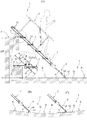
図1(A)及び図2は、本発明の好適な実施形態に係る可搬式仮設階段の構成を示す側面図及び正面図である。 FIG. 1A and FIG. 2 are a side view and a front view showing the configuration of a portable temporary staircase according to a preferred embodiment of the present invention.
図1及び図2には、鉄道の軌道Tと、鉄道内の上部床を構成するプラットホームPとが示されている。プラットホームPの縁部と軌道Tとの間には、可搬式架設階段1(以下、「階段1」という。)が懸架される。プラットホームPと軌道Tとの高低差ΔHは、約1.2〜1.5m(例えば、1.3m)であり、階段1は、水平面に対して所定範囲内の傾斜角θをなして全体的に傾斜する。本例において、傾斜角θは、35〜55度の範囲内、好ましくは、40〜50度の範囲内の範囲内の角度(例えば、43度)に予め設定される。
1 and 2 show a railroad track T and a platform P constituting an upper floor in the railroad. A portable stairs 1 (hereinafter referred to as “
階段1は、左右一対の側桁2と、左右の側桁2によって支持された複数の踏み板(段板)3と、片側の側板2に取付けられた折り畳み可能な手摺り組立体4と、各側桁2の上端部に配置された支承部5と、各側板2の下端部に配置された脚部6とから構成される。本例において、傾斜角θは、水平面に対する側桁2の軸芯の角度である。側桁2、踏み板3、手摺り組立体4、支承部5及び脚部6の主要部は、アルミニウム合金製部材の加工品からなり、樹脂、ゴム等の可撓性弾性部材や、高剛性の鋼製部材又は鋼製部品等が、必要に応じて各部品の適所に配設される。支承部5は、プラットホームPの縁部上面に接地する。脚部6は、軌道Tを構成する左右のレール(軌条)Rの間に配置され、道床Qの採石面等に接地する。図2に示す如く、絶縁カバー(図示せず)を収納可能な頂部開口形容器7が、片側の側桁2に一体的に形成される。絶縁カバーは、作業者等をレールRから絶縁すべく、階段1近傍のレールRを被覆するためものである。
The
踏み板3は、ボルト・ナット組立体31によって左右の側桁2に固定される。図1(A)の部分拡大図に示す如く、踏み板3は、概ね水平な踏み面30が形成されるように側桁2に固定される。本例において踏み面30は、側桁2に対して角度θをなす方向に配向される。
The
手摺り組立体4は、側桁2に支持された複数の支柱40と、支柱40の上端部に連結された手摺り部材41と、手摺り組立体4を構造的に安定させる方杖部材42とから構成される。各支柱40の下端部は、枢軸43によって側桁2に枢動可能又は回動可能に連結される。手摺り部材41は、枢動連結具44によって支柱40の上端部に枢動可能又は回動可能に連結される。方杖部材42の一端は、枢軸45によって支柱40の中間高さ位置(下端部及び上端部の間の所定高さ)に枢動可能又は回動可能に連結される。方杖部材42の他端は、係止具46を有し、係止具46は、手摺り部材41の中央部に突設されたピン47に対して係脱可能に連結される。
The
図3は、手摺り組立体4を折り畳んだ状態で示す階段1の側面図である。係止具46とピン47との係合を解くことにより、手摺り組立体4の構造的安定性を喪失させ、図3に示す如く、手摺り組立体4を折り畳むことができる。係止具46は、手摺り部材41上のピン48に対して係止され、手摺り組立体4は、図3に示す格納位置(折り畳んだ状態)に保持される。
FIG. 3 is a side view of the
図1(A)の部分拡大図に示すように、支承部5は、水平杆50と、水平杆50の下面に取付けられた複数の着座部材51とから構成される。側桁2の上端部には、水平方向に間隔を隔てた複数のボルト孔53が穿設される。水平杆50は、ボルト孔53を貫通するボルト・ナット組立体52によって側桁2の上端部に堅固に固定され、側桁2からプラットホームP側に水平に突出する。弾性着座部材51は、樹脂又はゴム等の弾性部材からなり、プラットホームPの縁部上面に着座する。弾性着座部材51がプラットホームPの縁部上面に着座することにより、側桁2の傾斜角θは実質的に固定され、踏み面30の水平性が確保される。
As shown in the partially enlarged view of FIG. 1A, the support portion 5 is composed of a
水平杆50は、ボルト・ナット組立体52の弛緩・解放によって側桁2から取り外すことができる。側桁2には、ボルト孔53と異なる高さ位置において水平杆50を側桁2に固定するためのボルト孔54が穿設される。
The
図4(A)は、高低差ΔHよりも小さい高低差ΔH'のプラットホームPに対して階段1を架設した状態を示す側面図である。図4(A)には、最上段の踏み板3の近傍に位置するボルト孔54にボルト・ナット組立体52を挿通して水平杆50を固定した状態が示されている。高低差ΔH'が更に小さい場合には、最上段よりも更に下側の踏み板3の近傍に位置するボルト孔54に対して水平杆50を固定しても良い。
FIG. 4A is a side view showing a state where the
図1(A)に示すように、側桁2には、階段1の不使用時に水平杆50を格納位置に保持するためのボルト孔55が更に穿設される。図3に破線で示す如く、水平杆50は、ボルト孔55に挿通したボルト・ナット組立体52によって側桁2と平行に配向され、側桁2に保持される。このような状態では、水平杆50は、側桁2の幅寸法の範囲内に納まるように配置される。
As shown in FIG. 1A, the
図5は、図3に示す格納位置の階段1を積み重ねた状態を示す側面図である。
FIG. 5 is a side view showing a state in which the
図3に示す如く、手摺り組立体4を折り畳み、ボルト孔55によって水平杆50を保持した格納位置の階段1は、図5に示す如く、上下に積み重ねることができる。側桁2の上端部及び下端部には、階段1の積み重ねを可能にするスペーサ9が一体的に形成される。このような構成によれば、図5に示すように多数の階段1を駅の倉庫、保管庫等にコンパクトに収納し得るので、実用的に極めて有利である。また、このようなコンパクトな収納形態の階段1は、その移送時にも極めて有利である。
As shown in FIG. 3, the
次に、図1、図3及び図4を参照して脚部6の構成について更に説明する。図1(A)の部分拡大図に示すように、脚部6は、側桁2の下端部に固定された保持具60と、保持具60によって側桁2に連結された伸縮杆61と、伸縮杆61の先端部(下端部)に連結された接地部材62とから構成される。伸縮杆61は、例えば、補強用の金属製芯材を内装した角形の金属製管材からなる。保持具60を貫通する螺子又はボルト等の係留具65が、伸縮杆61の螺子孔63に螺入し、伸縮杆61を側桁2に同軸状且つ一体的に連結する。伸縮杆61には、多数の螺子孔63が等間隔に穿設されており、保持具60には、複数の係留具65が螺子孔63と同一の間隔に配設される。係留具65と螺子孔63との相対位置は、プラットホームPと軌道Tとの高低差ΔHに相応して適切に設定される。
Next, the configuration of the
図3に示す如く、伸縮杆61及び側桁2の全長は、伸縮杆61の伸縮位置に相応して、長さL1〜L2の範囲内で設定変更することができ、係留具65は、伸縮杆61の伸縮位置に相応する螺子孔63に螺入され且つ締付けられる。例えば、プラットホームP及び軌道Tの高低差ΔHが比較的小さい場合、図1(B)に示す如く、伸縮杆61の伸長寸法を短縮し、階段1を高低差ΔHに適応させることができる。長さL1及びL2の差、即ち、伸縮杆61の伸長可能寸法ΔLは、例えば、300〜400mm程度の値に設定される。
As shown in FIG. 3, the total length of the
図1(A)に示す如く、接地部材62は、伸縮杆61の端部を貫通するボルト・ナット組立体64によって伸縮杆61に連結される。ボルト・ナット組立体64の軸部は、接地部材62の枢動可能又は回動可能に支承する。接地部材62は、樹脂又はゴム等の弾性部材からなり、道床Qの採石面等に接地する。所望により、接地部材62の枢動又は回動を利用して、側桁2の傾斜角θを図1(C)に示すように角度θ'に変化させることも可能である。但し、この角度変化は、踏み面30の水平性又は歩行感を大きく損なうことがない範囲のものである。
As shown in FIG. 1A, the grounding
また、比較的大きくカーブした多くの軌道では、道床Qの上面は、図4(B)及び図4(C)に示すように傾斜する。このような軌道においても、接地部材62の枢動によって側桁2の傾斜角θを維持することができる。
Further, in many tracks having relatively large curves, the upper surface of the road bed Q is inclined as shown in FIGS. 4B and 4C. Even in such a track, the inclination angle θ of the
次に、上記階段1の使用方法について説明する。
Next, the usage method of the said
階段1は、手摺り組立体4を折り畳み、ボルト孔55によって水平杆50を格納位置に保持し、更には、伸縮杆61を引き込んだ状態で、図5に示す如く積み重ねられ、駅の倉庫等に保管される。使用において、作業者等は、この状態の階段1をプラットホームPの使用部位に持ち運び、プラットホームP上で手摺り組立体4を起立させるとともに、高低差Hに相応するように水平杆50を側桁2に固定し且つ伸縮杆61の伸縮位置を設定し、しかる後、図1及び図4に示す如く、接地部材62を道床Qの採石面等に接地させるとともに、支承部5の着座部材51をプラットホームPの縁部上面に着座させる。
The
これらの作業は、プラットホームP上の作業者等によって実施することができるので、作業者等は、予め軌道T上に降りることなく、階段1をプラットホームPに設置することができる。これは、作業の効率、迅速性及び安全性等を考慮すると、極めて有利である。なお、最終的な階段1の微調整等は、必要に応じて、階段1をプラットホームPに設置した後に実施すれば良い。
Since these operations can be performed by an operator or the like on the platform P, the operator or the like can install the
図6は、支承部5と、プラットホームPの縁部上面との位置関係を示す断面図である。 FIG. 6 is a cross-sectional view showing the positional relationship between the support portion 5 and the upper surface of the edge of the platform P.
図6(A)に示す如く、左右の側桁2に夫々設けられた各水平杆50は、水平杆50の軸線方向に間隔を隔てて配置された少なくとも2つの着座部材51を有する。階段1が所定の傾斜角θで傾斜する場合、2つの着座部材51は、階段1の重量によって均等に圧縮変形した状態でプラットホームPの縁部上面に着座する。しかしながら、プラットホームPの上面の傾斜、勾配又は不陸等や、接地部材62の接地位置の相違等により、プラットホームPの上面に対する階段1の傾斜角度が所定の傾斜角θと相違することがある。
As shown in FIG. 6 (A), each
図6(B)及び図6(C)に示す如く、プラットホームPの上面に対する階段1の傾斜角度θ1、θ2が所定の傾斜角θと若干相違する場合には、一方の着座部材51が比較的大きく圧縮変形する。このため、2つの着座部材51は、プラットホームPに対する支承部5の着座状態を維持する。他方、図6(D)及び図6(E)に示す如く、プラットホームPの上面に対する階段1の傾斜角度θ3、θ4が所定の傾斜角θと大きく相違する場合、一方の着座部材51がプラットホームPから離間する。しかし、他方の着座部材51が大きく圧縮変形し、プラットホームPに対する支承部5の着座状態を維持する。
As shown in FIGS. 6B and 6C, when the inclination angles θ1 and θ2 of the
即ち、各々の水平杆50は、その軸線方向に間隔を隔てて配置された複数の着座部材51を有し、着座部材51の弾力的な変形により全着座部材51がプラットホームPの上面に着座し、或いは、一部の着座部材51がプラットホームPに上面から離間するが、少なくとも一つの着座部材51がプラットホームPに着座した状態を維持することにより、実際の階段1の傾斜角度θ1〜θ4と、所定の傾斜角θとの相違を補償する。
That is, each
図1及び図4には、階段1をプラットホームPに設置した状態が示されている。作業者等は、図1及び図4に示す如く前向き歩行で階段1を昇降し得る。このため、作業者等は、昇降時に工具等を携行した状態であっても、プラットホームP及び軌道Tの間を比較的容易に昇降することができる。しかも、作業者等は、手摺り部材41を手指で掴んだ状態で階段1を昇降歩行し得るので、作業者等の昇降動作の安全性は、かなり向上する。
1 and 4 show a state in which the
なお、使用後の階段1は、プラットホームP上の作業者等によって、プラットホームP上に持ち上げられる。手摺り組立体4は、格納位置(図3)に折り畳まれ、階段1は、図5に示す如く、積み重ねられ、嵩張ることなくコンパトクトに倉庫、保管庫等に収納される。
The used
以上、本発明の好適な実施形態及び実施例について詳細に説明したが、本発明は上記実施形態及び実施例に限定されるものではなく、特許請求の範囲に記載された本発明の範囲内で種々の変形又は変更が可能である。 The preferred embodiments and examples of the present invention have been described in detail above. However, the present invention is not limited to the above-described embodiments and examples, and is within the scope of the present invention described in the claims. Various modifications or changes are possible.
例えば、本発明の仮設階段は、深夜等に実施される保守・点検作業の際に使用し得るばかりでなく、鉄道の運行中にプラットホームから軌道上に落下した落下物等を回収するための昇降手段としても有効に使用し得る。 For example, the temporary staircase of the present invention can be used not only for maintenance / inspection work carried out at midnight or the like, but also for raising and lowering to collect fallen objects that fall on the track from the platform during railway operation. It can also be used effectively as a means.
また、上記実施例では、階段構成要素(側桁、踏み板、手摺り組立体等)の主要部は、アルミニウム合金製部材の加工品からなるものとして説明したが、他の合金製部品や、鋼製部品、或いは、樹脂製部品によって階段構成要素を製作しても良い。 In the above embodiment, the main part of the staircase components (side girders, footboards, handrail assemblies, etc.) has been described as being made of a processed product of an aluminum alloy member, but other alloy parts, steel The staircase component may be manufactured using a manufactured part or a resin part.
更に、上記実施例では、仮設階段の片側のみに手摺り組立体を配設したが、仮設階段の両側に手摺り組立体を配設することも可能である。 Further, in the above embodiment, the handrail assembly is disposed only on one side of the temporary staircase, but the handrail assembly may be disposed on both sides of the temporary staircase.
また、上記実施例においては、支承部は、ボルト・ナット組立体によって取外し可能に側桁に固定されるが、階段の不使用時に格納位置に移動するように支承部を可動式に構成しても良い。 Further, in the above embodiment, the support portion is detachably fixed to the side beam by the bolt and nut assembly, but the support portion is configured to be movable so that it moves to the storage position when the stairs are not used. Also good.
更には、階段構成要素の形状、各部構造及び寸法等は、仮設階段の形状及び寸法等に相応して適宜設計変更し得るものである。 Further, the shape, the structure and dimensions of the staircase components can be appropriately changed according to the shape and dimensions of the temporary staircase.
本発明は、鉄道のプラットホームと軌道(線路)との間に歩行可能な昇降通路を形成する可搬式仮設階段に適用される。本発明の可搬式仮設階段によれば、鉄道内の上部床を構成するプラットホームと軌道との間の段差部に階段式昇降路を形成し、プラットホーム及び軌道の間における作業者等の昇降移動を容易にするとともに、作業者等の昇降移動の安全性を向上することができるので、実用的に極めて有利である。 The present invention is applied to a portable temporary stair that forms an elevating walkway between a railway platform and a track (track). According to the portable temporary staircase of the present invention, a stepped hoistway is formed at the step portion between the platform and the track constituting the upper floor in the railway, so that the operator and the like can move up and down between the platform and the track. Since it can make it easy and the safety | security of the raising / lowering movement of an operator etc. can be improved, it is very advantageous practically.
1 可搬式仮設階段
2 側桁
3 踏み板
4 手摺り組立体
5 支承部
6 脚部
7 頂部開口形容器
P プラットホーム
T 軌道
R レール(軌条)
Q 道床
ΔH、ΔH' 高低差
θ 傾斜角
DESCRIPTION OF
Q Road bed ΔH, ΔH 'Height difference θ Inclination angle
Claims (4)
各側桁の上端部分に配置され、鉄道のプラットホームの縁部上面に支承されるとともに、踏み板上面の水平性を確保すべく前記縁部上面に着座する支承部と、
各側桁の下端部分に配置され、鉄道の軌道の上面に接地する脚部と、
少なくとも一方の側桁に配設された折り畳み可能な手摺り組立体とを有し、
前記側桁は、水平面に対して所定範囲内の角度をなして傾斜するように前記プラットホームの縁部上面と前記軌道との間に架設され、前記踏み板は、前向き歩行で昇降可能な階段を前記プラットホームの縁部上面と前記軌道との間に形成することを特徴とする可搬式仮設階段。 A portable temporary stair having left and right side girders and a plurality of step boards supported by the side girders,
A support portion that is disposed at the upper end portion of each side beam, is supported on the upper surface of the edge of the railway platform, and is seated on the upper surface of the edge in order to ensure the level of the upper surface of the tread plate;
Legs placed at the lower end of each side beam and grounded to the upper surface of the railroad track,
A foldable handrail assembly disposed on at least one side beam,
The side girders are installed between the upper surface of the platform edge and the track so as to incline at an angle within a predetermined range with respect to a horizontal plane. A portable temporary staircase formed between an upper surface of an edge of a platform and the track.
Priority Applications (1)
| Application Number | Priority Date | Filing Date | Title |
|---|---|---|---|
| JP2015239160A JP6693733B2 (en) | 2015-12-08 | 2015-12-08 | Temporary stairs |
Applications Claiming Priority (1)
| Application Number | Priority Date | Filing Date | Title |
|---|---|---|---|
| JP2015239160A JP6693733B2 (en) | 2015-12-08 | 2015-12-08 | Temporary stairs |
Publications (2)
| Publication Number | Publication Date |
|---|---|
| JP2017106191A true JP2017106191A (en) | 2017-06-15 |
| JP6693733B2 JP6693733B2 (en) | 2020-05-13 |
Family
ID=59059129
Family Applications (1)
| Application Number | Title | Priority Date | Filing Date |
|---|---|---|---|
| JP2015239160A Active JP6693733B2 (en) | 2015-12-08 | 2015-12-08 | Temporary stairs |
Country Status (1)
| Country | Link |
|---|---|
| JP (1) | JP6693733B2 (en) |
Cited By (6)
| Publication number | Priority date | Publication date | Assignee | Title |
|---|---|---|---|---|
| CN108519765A (en) * | 2018-04-11 | 2018-09-11 | 陈波 | Multi-function metal ladder control platform |
| JP2020112001A (en) * | 2019-01-16 | 2020-07-27 | 特殊梯子製作所有限会社 | Ladder with handrail |
| CN114017097A (en) * | 2021-09-29 | 2022-02-08 | 中铁第四勘察设计院集团有限公司 | High evacuation platform for shield tunnel of high-speed magnetic levitation railway |
| CN114183066A (en) * | 2021-12-10 | 2022-03-15 | 广东电网有限责任公司 | Insulating ladder |
| EP3807472A4 (en) * | 2018-06-12 | 2022-07-13 | Usinage 55 | Telescopic staircase system and uses thereof |
| KR102423422B1 (en) * | 2021-11-18 | 2022-07-21 | 주식회사 에스티 | Stairs for variable length bridge inspection facilities and their construction methods |
-
2015
- 2015-12-08 JP JP2015239160A patent/JP6693733B2/en active Active
Cited By (7)
| Publication number | Priority date | Publication date | Assignee | Title |
|---|---|---|---|---|
| CN108519765A (en) * | 2018-04-11 | 2018-09-11 | 陈波 | Multi-function metal ladder control platform |
| EP3807472A4 (en) * | 2018-06-12 | 2022-07-13 | Usinage 55 | Telescopic staircase system and uses thereof |
| JP2020112001A (en) * | 2019-01-16 | 2020-07-27 | 特殊梯子製作所有限会社 | Ladder with handrail |
| CN114017097A (en) * | 2021-09-29 | 2022-02-08 | 中铁第四勘察设计院集团有限公司 | High evacuation platform for shield tunnel of high-speed magnetic levitation railway |
| KR102423422B1 (en) * | 2021-11-18 | 2022-07-21 | 주식회사 에스티 | Stairs for variable length bridge inspection facilities and their construction methods |
| CN114183066A (en) * | 2021-12-10 | 2022-03-15 | 广东电网有限责任公司 | Insulating ladder |
| CN114183066B (en) * | 2021-12-10 | 2024-02-27 | 广东电网有限责任公司 | Insulating ladder |
Also Published As
| Publication number | Publication date |
|---|---|
| JP6693733B2 (en) | 2020-05-13 |
Similar Documents
| Publication | Publication Date | Title |
|---|---|---|
| JP6693733B2 (en) | Temporary stairs | |
| US3664456A (en) | Conveyance servicing structure | |
| US20170292349A1 (en) | Mobile well servicing units and related methods | |
| JP6159094B2 (en) | Moving scaffold | |
| US6772860B1 (en) | Helicopter access platform | |
| US6802391B2 (en) | Aircraft non-ambulatory/ambulatory boarding and off-loading system | |
| JP6167025B2 (en) | Stair lifting device and method for lifting heavy objects | |
| US20150259979A1 (en) | Ladder and Storage Rack Maintenance Facility Including the Same | |
| JP6709089B2 (en) | Quick assembly scaffolding | |
| CN111520064A (en) | Multifunctional operation ladder vehicle | |
| KR20130029627A (en) | Transporting vehicle moving on the rail for transporting load on the stairway | |
| RU199169U1 (en) | ESTACADA | |
| KR101473245B1 (en) | Insulated ladder carriage for rail | |
| US9902406B2 (en) | Commuter train and railway car exit ladder assembly and methods of storage and use | |
| KR20060071595A (en) | A moving work-stand adjustable in height and inclination | |
| US20060086568A1 (en) | Scaffolding structure | |
| KR20180070002A (en) | Ramp variable stairs | |
| US3625306A (en) | Conveyance servicing structure | |
| CN211223423U (en) | Movable type traveling rail operation vehicle suitable for urban vehicle maintenance | |
| CN211114724U (en) | Movable three-layer operation platform | |
| CN210919091U (en) | Waterproof board platform truck with flexible work platform | |
| CN218235022U (en) | Mounting platform of passenger train overhead air conditioner | |
| KR101683403B1 (en) | Cable inspection available rail road emergency exit route | |
| KR200319764Y1 (en) | Freight car for cement transport | |
| KR102578415B1 (en) | Mobile boarding device for maintenance work on large motor |
Legal Events
| Date | Code | Title | Description |
|---|---|---|---|
| A621 | Written request for application examination |
Free format text: JAPANESE INTERMEDIATE CODE: A621 Effective date: 20181113 |
|
| A977 | Report on retrieval |
Free format text: JAPANESE INTERMEDIATE CODE: A971007 Effective date: 20190821 |
|
| A131 | Notification of reasons for refusal |
Free format text: JAPANESE INTERMEDIATE CODE: A131 Effective date: 20190823 |
|
| A601 | Written request for extension of time |
Free format text: JAPANESE INTERMEDIATE CODE: A601 Effective date: 20191003 |
|
| A521 | Request for written amendment filed |
Free format text: JAPANESE INTERMEDIATE CODE: A523 Effective date: 20191127 |
|
| TRDD | Decision of grant or rejection written | ||
| A01 | Written decision to grant a patent or to grant a registration (utility model) |
Free format text: JAPANESE INTERMEDIATE CODE: A01 Effective date: 20200402 |
|
| A61 | First payment of annual fees (during grant procedure) |
Free format text: JAPANESE INTERMEDIATE CODE: A61 Effective date: 20200416 |
|
| R150 | Certificate of patent or registration of utility model |
Ref document number: 6693733 Country of ref document: JP Free format text: JAPANESE INTERMEDIATE CODE: R150 |
|
| R250 | Receipt of annual fees |
Free format text: JAPANESE INTERMEDIATE CODE: R250 |
|
| R250 | Receipt of annual fees |
Free format text: JAPANESE INTERMEDIATE CODE: R250 |