JP2017104959A - lathe - Google Patents
lathe Download PDFInfo
- Publication number
- JP2017104959A JP2017104959A JP2015242110A JP2015242110A JP2017104959A JP 2017104959 A JP2017104959 A JP 2017104959A JP 2015242110 A JP2015242110 A JP 2015242110A JP 2015242110 A JP2015242110 A JP 2015242110A JP 2017104959 A JP2017104959 A JP 2017104959A
- Authority
- JP
- Japan
- Prior art keywords
- tailstock
- axis
- spindle
- main shaft
- shaft
- Prior art date
- Legal status (The legal status is an assumption and is not a legal conclusion. Google has not performed a legal analysis and makes no representation as to the accuracy of the status listed.)
- Granted
Links
- 210000000078 claw Anatomy 0.000 description 15
- 238000003754 machining Methods 0.000 description 7
- 238000005452 bending Methods 0.000 description 4
- 230000005489 elastic deformation Effects 0.000 description 4
- 238000000034 method Methods 0.000 description 4
- 238000006243 chemical reaction Methods 0.000 description 3
- 238000001514 detection method Methods 0.000 description 2
- 238000006073 displacement reaction Methods 0.000 description 2
- 238000005192 partition Methods 0.000 description 2
- 230000002093 peripheral effect Effects 0.000 description 2
- 238000003825 pressing Methods 0.000 description 1
Images


Landscapes
- Turning (AREA)
Abstract
Description
本発明は、心押装置を備えた旋盤に関し、特に、コンパクトな構造にすべく前記心押装置を主軸台の前端面に設けた旋盤に関する。 The present invention relates to a lathe provided with a tailstock device, and more particularly, to a lathe provided with the tailstock device on a front end surface of a headstock for a compact structure.
心押装置を主軸台の前端面に設けた構造の上記旋盤として、従来、特開2001−87904号公報(下記特許文献1)に開示される旋盤が知られている。この旋盤は、特許文献1に開示されるように、割り込み式のテールストック装置を備えており、このテールストック装置は、基端が主軸台の前端面に枢着されて、主軸の軸線に対して近接隔離する方向に揺動する進退部材と、この進退部材に主軸軸線方向に移動可能に装着された移動部材と、主軸軸線方向に付圧する装置を介して前記移動部材に装着されたテールストックと、進退部材を進退させる進退駆動装置と、移動部材を任意の、又は予め定めた複数の位置で進退部材に固定する固定具を備えている。
Conventionally, a lathe disclosed in Japanese Patent Laid-Open No. 2001-87904 (
この従来の旋盤によれば、前記テールストックを使用する場合には、まず、主軸に装着されたチャックにワークを把持させた状態で、前記進退駆動装置により前記進退部材を前記主軸の軸線方向に揺動させて、移動部材に装着されたテールストックをその軸線が主軸軸線と同軸になるように配置する。次に、前記付圧装置により、移動部材又はテールストックを主軸側に移動させて、当該テールストックをワークの中心穴に押し付け、この状態で所定の加工を行う。 According to this conventional lathe, when the tailstock is used, first, the advancing / retracting device is moved in the axial direction of the main shaft by the advancing / retreating drive device with the work gripped by a chuck mounted on the main shaft. The tail stock mounted on the moving member is arranged so that its axis is coaxial with the main axis. Next, the pressing device moves the moving member or the tail stock to the main shaft side, presses the tail stock against the center hole of the workpiece, and performs predetermined processing in this state.
一方、前記テールストックを使用しない場合には、前記進退駆動装置により前記進退部材を前記主軸の軸線から遠ざかる方向に揺動させ、加工に支障が生じないように、前記進退部材,移動部材及びテールストック等を予め設定した退避位置に移動させる。 On the other hand, when the tail stock is not used, the advancing / retreating member, the moving member, and the tail are moved so that the advancing / retreating member is swung away from the axis of the main shaft by the advancing / retreating drive device so as not to hinder processing. The stock or the like is moved to a preset retreat position.
このように、この従来の旋盤によれば、進退部材を揺動させることによって、テールストックを使用位置と退避位置との間で移動させることができ、その構造をコンパクトにすることができる。また、このような構造の旋盤では、テールストックが設けられる側の主軸と対向するように、もう一つの主軸を配設することができ、このような構成とすることで、テールストックを用いた加工が必要なワークを効率的に加工することが可能となる。 Thus, according to this conventional lathe, the tailstock can be moved between the use position and the retracted position by swinging the advance / retreat member, and the structure can be made compact. Further, in the lathe having such a structure, another main shaft can be disposed so as to face the main shaft on the side where the tail stock is provided. With this configuration, the tail stock is used. It is possible to efficiently process a workpiece that needs to be processed.
ところが、上記従来の旋盤は上述した利点を有するものの、その一方で、以下に説明するような問題があった。 However, although the conventional lathe has the above-described advantages, there are problems as described below.
即ち、上記従来のテールストック装置の進退部材は、その基端が主軸台の前端面に枢着されて、前記進退駆動装置によって揺動するように構成されているので、その構造的な剛性が低く、当該テールストックによってワークを安定して支持することができないという問題があった。このため、加工時に振動等を生じ易く、ワークの高精度な加工が阻害されていた。 That is, the advancing / retracting member of the conventional tailstock device is structured such that its base end is pivotally attached to the front end surface of the headstock and is swung by the advancing / retreating drive device. There is a problem that the work cannot be stably supported by the tailstock. For this reason, vibration or the like is likely to occur during machining, and high-precision machining of the workpiece is hindered.
また、前記進退部材は一つの湾曲又は屈曲したアーム状の部材から構成され、一端が主軸台の前端面に枢着されるとともに、他端にテールストックが配設された構造となっているので、当該湾曲又は屈曲したアーム状の進退部材は、テールストックをワークに押し当てた際に作用する反力(これに伴う曲げモーメント)によって弾性変形し易く、これによりテールストックが変位してその軸心が主軸軸線から芯ずれするという問題があった。そして、このようにテールストックが芯ずれすると、ワークの両端における芯がずれることになり、このような現象によってもワークの高精度な加工が阻害されていた。 Further, the advance / retreat member is composed of one curved or bent arm-shaped member, and one end is pivotally attached to the front end surface of the headstock and the other end is provided with a tailstock. The curved or bent arm-like advance / retreat member is easily elastically deformed by a reaction force (a bending moment accompanying it) when the tail stock is pressed against the work, and thereby the tail stock is displaced and its axis is moved. There was a problem that the core was misaligned from the spindle axis. If the tail stock is misaligned in this way, the cores at both ends of the work are misaligned, and this phenomenon also hinders high-precision machining of the work.
本発明は、以上の実情に鑑みなされたものであって、コンパクトな構造を有しながらも、従来に比べて、ワークの両端における芯をずれさせることなく、安定して支持することが可能な心押装置を備えた旋盤の提供を、その目的とする。 The present invention has been made in view of the above circumstances, and can be stably supported without shifting the cores at both ends of the workpiece as compared with the conventional one while having a compact structure. The purpose is to provide a lathe equipped with a tailstock device.
上記課題を解決するための本発明は、主軸と、該主軸を軸中心に回転自在に保持する主軸台と、前記主軸の前端面に装着され、ワークを保持するチャックと、工具を保持する刃物台と、前記主軸台に設けた心押装置とを少なくとも備え、前記主軸と刃物台とが前記主軸の軸線と平行な方向及び前記主軸の軸線と直交する方向に相対移動するように構成された旋盤であって、
前記心押装置は、
第1心押軸と、
前記第1心押軸を、前記主軸の軸線と同軸、且つ前記チャックに対向するように保持する保持部と、
前記保持部を前記主軸の軸線方向に進退可能に保持するハウジングと、
前記保持部を前記主軸の軸線方向に進退させる駆動部と、
一端が前記主軸台にそれぞれ固設され、他端が前記ハウジングにそれぞれ接続される2本の支持アームとを備えて構成されるとともに、
前記2本の支持アームは、前記チャックを挟み、且つ該チャックの外側にそれぞれ位置するように前記主軸台に固設された旋盤に係る。
The present invention for solving the above-described problems includes a main shaft, a main spindle that holds the main shaft rotatably about the shaft, a chuck that is mounted on the front end surface of the main shaft and holds a workpiece, and a blade that holds a tool. At least a base and a tailstock device provided on the headstock, wherein the main shaft and the tool rest are relatively moved in a direction parallel to the axis of the main shaft and a direction orthogonal to the axis of the main shaft. A lathe,
The tailstock device is
A first tailstock,
A holding portion for holding the first tailstock shaft so as to be coaxial with the axis of the main shaft and to face the chuck;
A housing for holding the holding portion so as to be movable back and forth in the axial direction of the main shaft;
A drive unit for moving the holding unit back and forth in the axial direction of the main shaft;
One end is fixed to the headstock, and the other end is configured to include two support arms respectively connected to the housing.
The two support arms relate to a lathe that is fixed to the headstock so as to sandwich the chuck and be positioned outside the chuck, respectively.
この旋盤によれば、例えば、まず、前記チャックによりワークを保持し、この状態で前記駆動部により前記保持部を前記主軸側に進出させて、前記第1心押軸をワークの中心穴に押し付ける。そして、この状態で、前記チャックによる把持を一旦解除した後、当該チャックによってワークを再把持する。これによりワークは主軸軸線に対して芯出しされ、前記チャック及び前記第1心押軸によって支持される。 According to this lathe, for example, the workpiece is first held by the chuck, and in this state, the holding portion is advanced to the spindle side by the driving portion, and the first tailstock shaft is pressed against the center hole of the workpiece. . In this state, after the gripping by the chuck is once released, the work is gripped again by the chuck. As a result, the workpiece is centered with respect to the spindle axis, and is supported by the chuck and the first tailstock shaft.
そして、この状態で前記主軸を回転させ、前記刃物台に装着された工具と、前記ワークとの相対的な移動により当該ワークが加工される。その際、前記工具は、前記2本の支持アーム間に形成される空間を通して前記ワークに接触し、これを加工する。 In this state, the spindle is rotated, and the workpiece is machined by relative movement between the tool mounted on the tool post and the workpiece. At that time, the tool comes into contact with the workpiece through a space formed between the two support arms and processes the workpiece.
そして、この旋盤では、上述のように、前記保持部が保持されるハウジングは、前記チャックを挟み、且つ前記一端が前記チャックの外側に位置するように、前記主軸台の前端面にそれぞれ固設された2本の支持アームによって支持されているので、従来のような、湾曲又は屈曲した一つのアーム状の部材からなり、一端が主軸台の前端面に枢着された進退部材によって支持される構成に比べて、その構造的な剛性が高く、前記第1心押軸によってワークを安定して支持することができ、この結果、当該ワークの高精度な加工を実現することができる。 In this lathe, as described above, the housing holding the holding portion is fixed to the front end surface of the headstock so that the chuck is sandwiched and the one end is positioned outside the chuck. Since it is supported by two supported arms, it is composed of one arm-like member that is bent or bent as in the prior art, and one end is supported by an advance / retreat member pivotally attached to the front end surface of the headstock. Compared to the configuration, the structural rigidity is high, and the workpiece can be stably supported by the first tailstock. As a result, high-precision machining of the workpiece can be realized.
また、前記2本の支持アームは、上記のように、その前記一端が前記チャックを挟み、且つ前記チャックの外側に位置するように、前記主軸台の前端面に固設されているので、従来に比べて、前記第1心押軸をワークに押し当てた際の反力によって生じる曲げモーメントが小さく、このため、前記支持アームに生じる弾性変形が抑制され、これにより、前記第1心押軸の変位や、これによってその軸心が主軸軸線から芯ずれするという従来の問題が解消される。 Further, as described above, the two support arms are fixed to the front end surface of the head stock so that the one end sandwiches the chuck and is located outside the chuck. , The bending moment generated by the reaction force when the first tailstock is pressed against the workpiece is small, so that the elastic deformation that occurs in the support arm is suppressed, whereby the first tailstock is The conventional problem that the center of the shaft is displaced from the main axis is eliminated.
尚、前記2本の支持アームは、その一端(固設端)を前記主軸軸線と直交する方向において可及的に主軸軸線に近づけることができ、このようにすることで、心押装置の構造的な剛性をより高めることができる。 The two support arms can have their one ends (fixed ends) as close as possible to the main shaft axis in the direction orthogonal to the main shaft axis, and in this way, the structure of the tailstock device The rigidity can be further increased.
斯くして、本発明に係る心押装置を備えた旋盤によれば、心押装置を主軸台の前端面に設けるというコンパクトな構造を採用しながら、当該心押装置が安定した高い剛性を備えているので、ワークを安定して支持することができ、この結果、当該ワークを高精度に加工することができる。 Thus, according to the lathe equipped with the tailstock device according to the present invention, the tailstock device has a stable and high rigidity while adopting a compact structure in which the tailstock device is provided on the front end surface of the headstock. Therefore, the workpiece can be stably supported, and as a result, the workpiece can be processed with high accuracy.
尚、本発明では、前記主軸の軸線と同軸、且つ前記第1心押軸に対向するように、前記チャックの前端面に固設された第2心押軸を備えていても良い。このような構成によれば、前記第2心押軸に前記ワークの中心穴の一方を押し当てた状態で、前記駆動部により前記保持部を前記主軸側に進出させて、前記第1心押軸を前記ワークの中心穴の他方に押し付け、これら第1及び第2心押軸によってワークを支持する。これにより、ワークは主軸軸線に対して芯出しされ、このように芯出しされたワークが前記チャックによって把持される。斯くして、この構成によれば、ワークを少ない動作でしかも正確に芯出して把持することができる。 In the present invention, a second tailstock shaft fixed to the front end surface of the chuck may be provided so as to be coaxial with the axis of the main shaft and to face the first tailstock shaft. According to such a configuration, in a state in which one of the center holes of the workpiece is pressed against the second tailstock, the holding portion is advanced to the spindle side by the driving portion, and the first tailstock is pushed. The shaft is pressed against the other center hole of the workpiece, and the workpiece is supported by the first and second tailstock shafts. Thereby, the workpiece is centered with respect to the spindle axis, and the workpiece thus centered is gripped by the chuck. Thus, according to this configuration, the workpiece can be accurately centered and gripped with a small amount of motion.
また、本発明に係る旋盤において、前記主軸はその軸線が水平になるように前記主軸台に保持され、前記刃物台は前記主軸の軸線より下方に配設されるとともに、当該主軸と刃物台とは垂直方向に相対移動するように構成され、
前記支持アームは、それぞれ前記一端から予め設定された長さ部分が水平に設けられた水平部と、この水平部から前記他端に向けて斜め上方に傾斜した傾斜部とから構成され、
更に、前記支持アームの水平部は前記主軸の軸線より下方に位置するとともに、前記ハウジングの下端部は前記支持アームの下端部より上方に位置するように構成されていても良い。
Further, in the lathe according to the present invention, the spindle is held on the spindle stock so that the axis thereof is horizontal, the tool post is disposed below the axis of the spindle, the spindle and the tool post, Is configured to move relative to the vertical direction,
The support arm is composed of a horizontal portion in which a predetermined length portion is provided horizontally from the one end, and an inclined portion inclined obliquely upward from the horizontal portion toward the other end,
Further, the horizontal portion of the support arm may be positioned below the axis of the main shaft, and the lower end portion of the housing may be positioned above the lower end portion of the support arm.
この構成によれば、前記主軸の軸線と前記支持アームの水平部との間に空間を形成することができ、例えば、この空間を、ワークを着脱するローディング装置のハンドの動作領域とすることができ、このようにすることでワーク着脱の自動化を図ることができる。 According to this configuration, a space can be formed between the axis of the main shaft and the horizontal portion of the support arm. For example, this space can be used as an operation region of the hand of the loading apparatus for attaching and detaching a workpiece. In this way, it is possible to automate the work attachment / detachment.
一方、前記刃物台を前記主軸の軸線より下方に配設するとともに、前記主軸と刃物台とを垂直方向に相対移動可能に設けることで、前記刃物台に装着された工具を、前記2本の支持アーム間に形成される空間を通して前記ワークに接触させることができ、これにより当該ワークを加工することができる。 On the other hand, the tool rest is disposed below the axis of the main spindle, and the main spindle and the tool rest are provided so as to be relatively movable in the vertical direction, so that the tool mounted on the tool rest can be The workpiece can be contacted through a space formed between the support arms, whereby the workpiece can be processed.
以上のように、本発明に係る旋盤によれば、前記保持部が保持されるハウジングが、前記チャックを挟み、且つ前記一端が前記チャックの外側に位置するように、前記主軸台の前端面にそれぞれ固設された2本の支持アームによって支持されているので、従来に比べて、その構造的な剛性が高く、前記第1心押軸によってワークを安定して支持することができ、この結果、当該ワークの高精度な加工を実現することができる。 As described above, according to the lathe according to the present invention, the housing on which the holding unit is held sandwiches the chuck, and the one end is positioned outside the chuck. Since it is supported by the two support arms fixed to each other, its structural rigidity is higher than in the prior art, and the work can be stably supported by the first tailstock. , High-precision machining of the workpiece can be realized.
また、前記2本の支持アームは、上記のように、その前記一端が前記チャックを挟み、且つ前記チャックの外側に位置するように、前記主軸台の前端面に固設されているので、従来に比べて、前記第1心押軸をワークに押し当てた際の反力によって生じる曲げモーメントが小さく、このため、前記支持アームに生じる弾性変形が抑制され、これにより、前記第1心押軸の変位や、これによってその軸心が主軸軸線から芯ずれするという従来の問題が解消される。 Further, as described above, the two support arms are fixed to the front end surface of the head stock so that the one end sandwiches the chuck and is located outside the chuck. , The bending moment generated by the reaction force when the first tailstock is pressed against the workpiece is small, so that the elastic deformation that occurs in the support arm is suppressed, whereby the first tailstock is The conventional problem that the center of the shaft is displaced from the main axis is eliminated.
このように、本発明に係る心押装置を備えた旋盤によれば、心押装置を主軸台の前端面に設けるというコンパクトな構造を採用しながら、当該心押装置が安定した高い剛性を備えているので、ワークを安定して支持することができ、この結果、当該ワークを高精度に加工することができる。 Thus, according to the lathe equipped with the tailstock device according to the present invention, the tailstock device has a stable and high rigidity while adopting a compact structure in which the tailstock device is provided on the front end surface of the headstock. Therefore, the workpiece can be stably supported, and as a result, the workpiece can be processed with high accuracy.
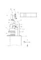
以下、本発明の具体的な実施の形態について、図面を参照しながら説明する。図1〜図6に示すように、本例の旋盤1は、中心軸(軸線)が水平になるように配設された主軸3と、この主軸3を、前記中心軸を中心に回転自在に保持する主軸台2と、主軸3の前端面に装着され、2つの把持爪5によってワークWを把持するチャック4と、工具Tを保持する刃物台(タレット)6と、前記主軸台2の前端面に取り付けられた心押装置10とを少なくとも備えている。
Hereinafter, specific embodiments of the present invention will be described with reference to the drawings. As shown in FIGS. 1 to 6, a
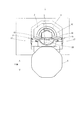
尚、本例のワークWは、四角柱形状をした基部Waと、この基部Waの端面の中心部に該端面から外方に延出されるように形成された円筒部Wbとから成り、更に、中心部には、基部Waの反対側の端面及び円筒部Wbの端面に開口するように中心穴Wcが穿孔されており、この基部Waの外周面が前記把持爪5によって把持される。
The workpiece W of this example includes a base portion Wa having a quadrangular prism shape, and a cylindrical portion Wb formed to extend outward from the end surface at the center of the end surface of the base portion Wa. A central hole Wc is drilled in the center portion so as to open to the end surface opposite to the base portion Wa and the end surface of the cylindrical portion Wb, and the outer peripheral surface of the base portion Wa is gripped by the gripping
前記主軸台2、主軸3及び刃物台6は旋盤としての基本的な構成の一部であり、一般的には、この他にベッド等を備えている。尚、本例の旋盤1では、適宜送り装置によって、前記主軸台2が前記主軸3の軸線と直交するX軸方向、及び主軸3の軸線と平行なZ軸方向に移動するように構成されており、前記刃物台6は軸移動しないようになっている。
The
前記心押装置10は、ハウジング23、第1支持アーム11、第2支持アーム15及び第1心押軸33などから構成される。
The
前記第1支持アーム11及び第2支持アーム15は、その一端が前記主軸台2の前端面(前記刃物台6側の端面)にそれぞれ固設され、他端が前記ハウジング23にそれぞれ接続される部材で、前記一端は、前記主軸3の軸線より下方位置で、前記チャック4を挟み、且つこのチャック4の外側にそれぞれ位置するように前記主軸台2の前端面に固設されている。
One end of each of the
また、この第1支持アーム11及び第2支持アーム15は、それぞれ前記一端から予め設定される長さ部分が水平になった水平部12,16と、この水平部12,16から前記他端に向けて斜め上方に傾斜し且つ主軸3の軸線側に屈曲した傾斜部13,17とからなり、このような構成によって、前記第1支持アーム11と第2支持アーム15との間に適宜空間が形成されるとともに、前記把持爪5と前記第1心押軸33との間に適宜空間が形成されている。
Further, the
前記ハウジング23は、図5に示すように、前記主軸3の軸線に沿い、且つ前記主軸3側が開口した収納穴21を備えており、この収納穴21内に、前記主軸3の軸線方向に移動可能に保持部材22が挿入されており、その下端部は、前記第1支持アーム11及び第2支持アーム15の下端より上方に位置している。
As shown in FIG. 5, the
前記保持部材22は、前記主軸3の軸線方向の略中心位置に形成される隔壁30を挟んで、前記主軸3の軸線と同軸上に位置するようにそれぞれ形成された、前記主軸3側の保持穴31及びその反対側のシリンダ穴23を備えている。そして、前記保持穴31には、第1心押軸33が、その先端部が前側に突出し、且つ軸中心に回転自在となるようにベアリング32を介して保持されている。
The holding
一方、前記シリンダ穴23には、前記主軸3側が大径部25、反対側が小径部26となった段付き状のロッド24が挿入されており、このシリンダ穴23は、前記ロッド24の小径部26に外嵌されるリング状の蓋体27によって封止されている。そして、ロッド24の小径部26側の端部は、前記ハウジング20の収納穴21の底面にボルトによって固定されている。
On the other hand, a stepped
また、前記隔壁30の前記ロッド24側の端面には凹状の第1液圧室28が形成され、また、前記小径部26、シリンダ穴23の内周面及び蓋体27によって形成される空間は第2液圧室29となっており、適宜供給路を介して、これら第1液圧室28及び第2液圧室29に選択的に圧油が供給されるようになっている。
Further, a concave first
斯くして、前記第2液圧室29に圧油が供給されると、保持部材22及びこれに支持される第1心押軸33が主軸3側に進出し、一方、前記第1液圧室28に圧油が供給されると、保持部材22及び第1心押軸33は後方に後退する。尚、符号34は、保持部材22の前記主軸3側の端面に連結される位置検出ロッドであり、この位置検出ロッド34の位置を適宜センサによって検出することで、第1心押軸33の進退位置を検出することができるようになっている。
Thus, when pressure oil is supplied to the second
また、前記2つの把持爪5間の、前記チャック4の前端面には、前記主軸3の軸線と同軸となり、且つ前記第1心押軸33に対向するように、第2心押軸35が固設されている。
Further, a
以上の構成を備えた本例の旋盤1によれば、例えば、まず、ワークWの円筒部Wbを図示しない適宜ローディング装置のハンドにより把持して、図5において紙面と垂直な方向に搬送し、当該ワークWを、前記2つの把持爪5の間に位置し、且つ第1心押軸33と第2心押軸35との間に位置するとともに、その中心穴Wcが主軸3の軸線と同軸となるように位置決めする。
According to the
次に、前記ハンドを前記主軸3側に移動させて、ワークWの中心穴Wcの前記主軸3側の開口部を前記第2心押軸35の先端部に押し当てる。そして、この状態で、前記第2液圧室29に圧油を供給して前記第1心押軸33を主軸3側に進出させ、その先端部を前記ワークWの中心穴Wcの前記主軸3とは反対側の開口部に押圧させる。これにより、第1心押軸33及び第2心押軸35によってワークWが芯出しされ、これらによって支持される。
Next, the hand is moved to the
次に、前記2つの把持爪5を閉じ、当該把持爪5によって前記ワークWの基部Waを把持した後、前記ハンドによる把持を解除し、当該ハンドを適宜退避させる。以上の動作により、ワークWの第1心押軸33及び第2心押軸35による支持、及び把持爪5による把持が完了する。
Next, after closing the two
ついで、前記主軸3を適宜回転させ、当該主軸3を適宜X軸方向及びZ軸方向に移動させることで、前記刃物台6に装着された工具TによってワークWが加工される。その際、図6に示すように、前記工具Tは、前記第1支持アーム11と第2支持アーム15との間に形成される空間を通して前記ワークWに接触し、これを加工する。
Next, the workpiece W is machined by the tool T mounted on the
そして、上記加工を終了すると、前記ローディング装置のハンドを移動させて、当該ハンドにより前記ワークWの円筒部Wbを把持した後、前記2つの把持爪5を開くとともに、前記第1液圧室28に圧油を供給して前記第1心押軸33を後退させ、これにより、ワークWの第1心押軸33及び第2心押軸35による支持、及び前記把持爪5による把持を解除する。
When the processing is completed, the hand of the loading device is moved and the cylindrical portion Wb of the workpiece W is gripped by the hand, the two
次に、前記ハンドを図5において紙面と垂直な方向に搬送することで、ワークWを排出する。そして、以後、以上と同様の動作を繰り返すことにより、複数のワークWを連続的に加工することができる。 Next, the work W is discharged by conveying the hand in a direction perpendicular to the paper surface in FIG. Then, a plurality of workpieces W can be processed continuously by repeating the same operation as described above.
斯くして、本例の旋盤1では、上述したように、第1心押軸33を保持するハウジング20が、前記チャック4を挟み、且つ前記一端が前記チャック4の外側に位置するように、前記主軸台2の前端面にそれぞれ固設された第1支持アーム11及び第2支持アーム15によって支持されているので、上述した従来の心押装置の構成に比べて、その構造的な剛性が高く、このため前記第1心押軸33によりワークWを安定して支持することができ、この結果、当該ワークWの高精度な加工を実現することができる。
Thus, in the
また、本例の第1支持アーム11及び第2支持アーム15の構成によれば、上述した従来の心押装置の構成に比べて、前記第1心押軸33をワークWに押し当てた際に生じる曲げモーメントが小さく、このため、前記第1支持アーム11及び第2支持アーム15に生じる弾性変形が抑制され、これにより、前記第1の心押軸の変位や、これによってその軸心が主軸軸線から芯ずれするという従来の問題が解消される。
Further, according to the configuration of the
また、本例の旋盤1では、前記チャック4の前端面に、前記第1心押軸33に対向する第2心押軸35を設け、ワークWをこれら第1心押軸33及び第2心押軸35によって芯出しするようにしているので、ワークWを正確に芯出しすることができ、ワークWの高精度な加工を実現することができる。
Further, in the
また、本例の旋盤1では、前記第1支持アーム11及び第2支持アーム15をそれぞれ水平部12,16と傾斜部13,17とから構成し、水平部12,16を主軸3の軸線より下方に位置させるとともに、前記ハウジングの下端部を第1支持アーム11及び第2支持アーム15の下端部より上方に位置させた構成としているので、主軸3の軸線と第1支持アーム11及び第2支持アーム15との間に空間を形成することができ、上述したように、この空間を、ワークWを着脱するローディング装置のハンドの動作領域とすることができ、このようにすることでワーク着脱の自動化を図ることができる。
Further, in the
また、刃物台6を主軸3の軸線より下方に配設するとともに、主軸3を垂直方向(X軸方向)に移動可能に設けているので、刃物台6に装着された工具Tを、第1支持アーム11と第2支持アーム15との間に形成された空間を通して前記ワークWに接触させることができ、これにより当該ワークWを加工することができる。
In addition, the
以上、本発明の一具体的な実施の形態について説明したが、本発明が採り得る具体的な態様は何らこれに限定されるものではない。 The specific embodiment of the present invention has been described above, but the specific mode that the present invention can take is not limited to this.
例えば、前記チャック4及び第1心押軸33によって十分にワークWの芯出しができるのであれば、前記第2心押軸35は特にこれを設ける必要はない。また、チャック4の態様も上述した2つの把持爪5(所謂、2方爪)を備えたものに限られるものではなく、3つ爪や4つ爪を備えたチャックであっても良い。
For example, if the workpiece W can be sufficiently centered by the chuck 4 and the
また、主軸台2及び刃物台6は、これらが相対的に前記主軸3の軸線に沿った方向及びこの軸線と直交する方向に移動できるように構成されていれば良く、ワークWの長さに応じて、心押装置10が主軸軸線方向に移動可能となっていても良い。
The
また、上例では、保持部材22のシリンダ穴23に形成した前記第1液圧室28及び第2液圧室29に圧油を供給することによって、第1心押軸33を進退させるようにしたが、当然のことながら、他の機構によって第1心押軸33を進退させるようにしても良い。
In the above example, the
また、上述したローディング装置を用いない場合には、そのハンドの動作領域を考慮する必要がなく、この場合には、第1支持アーム11及び第2支持アーム15の前記一端(固設端)を、前記主軸3の軸線と直交する方向において、可及的に主軸3の軸線に近づけることができる。このようにすることで、従来に比べて、心押装置10の構造的な剛性をより高めることができる。そして、このように剛性を高めることで、前記第1心押軸33をワークWに押し当てた際の曲げモーメントによる、第1支持アーム11及び第2支持アーム15の弾性変形をより効果的に抑制することができ、これにより、前記第1心押軸33の変位や、これによってその軸心が主軸3の軸線から芯ずれするという従来の問題をより効果的に解消することができる。
Further, when the above-described loading device is not used, it is not necessary to consider the operation area of the hand. In this case, the one end (fixed end) of the
1 旋盤
2 主軸台
3 主軸
4 チャック
5 把持爪
6 刃物台
10 心押装置
11 第1支持アーム
12 水平部
13 傾斜部
15 第2支持アーム
16 水平部
17 傾斜部
20 ハウジング
22 保持部材
24 ロッド
28 第1液圧室
29 第2液圧室
33 第1心押軸
35 第2心押軸
T 工具
W ワーク
DESCRIPTION OF
Claims (3)
前記心押装置は、
第1心押軸と、
前記第1心押軸を、前記主軸の軸線と同軸、且つ前記チャックに対向するように保持する保持部と、
前記保持部を前記主軸の軸線方向に進退可能に保持するハウジングと、
前記保持部を前記主軸の軸線方向に進退させる駆動部と、
一端が前記主軸台にそれぞれ固設され、他端が前記ハウジングにそれぞれ接続される2本の支持アームとを備えて構成されるとともに、
前記2本の支持アームは、前記チャックを挟み、且つ該チャックの外側にそれぞれ位置するように前記主軸台に固設されていることを特徴とする旋盤。 A main spindle, a main spindle that holds the main spindle rotatably about the axis, a chuck that is attached to the front end surface of the main spindle and holds a workpiece, a tool post that holds a tool, and a tailstock provided on the main spindle A lathe comprising at least an apparatus, wherein the spindle and the tool post are configured to move relative to each other in a direction parallel to the axis of the spindle and in a direction perpendicular to the axis of the spindle,
The tailstock device is
A first tailstock,
A holding portion for holding the first tailstock shaft so as to be coaxial with the axis of the main shaft and to face the chuck;
A housing for holding the holding portion so as to be movable back and forth in the axial direction of the main shaft;
A drive unit for moving the holding unit back and forth in the axial direction of the main shaft;
One end is fixed to the headstock, and the other end is configured to include two support arms respectively connected to the housing.
The lathe characterized in that the two support arms are fixed to the headstock so as to sandwich the chuck and to be respectively located outside the chuck.
前記支持アームは、それぞれ前記一端から予め設定された長さ部分が水平に設けられた水平部と、この水平部から前記他端に向けて斜め上方に傾斜した傾斜部とから構成され、
更に、前記支持アームの水平部は前記主軸の軸線より下方に位置するとともに、前記ハウジングの下端部は前記支持アームの下端部より上方に位置していることを特徴とする請求項1又は2記載の旋盤。
The spindle is held on the spindle stock so that the axis thereof is horizontal, the tool post is disposed below the axis of the spindle, and the spindle and the tool post are relatively moved in the vertical direction. Configured,
The support arm is composed of a horizontal portion in which a predetermined length portion is provided horizontally from the one end, and an inclined portion inclined obliquely upward from the horizontal portion toward the other end,
The horizontal portion of the support arm is located below the axis of the main shaft, and the lower end portion of the housing is located above the lower end portion of the support arm. Lathe.
Priority Applications (1)
| Application Number | Priority Date | Filing Date | Title |
|---|---|---|---|
| JP2015242110A JP6539577B2 (en) | 2015-12-11 | 2015-12-11 | lathe |
Applications Claiming Priority (1)
| Application Number | Priority Date | Filing Date | Title |
|---|---|---|---|
| JP2015242110A JP6539577B2 (en) | 2015-12-11 | 2015-12-11 | lathe |
Publications (2)
| Publication Number | Publication Date |
|---|---|
| JP2017104959A true JP2017104959A (en) | 2017-06-15 |
| JP6539577B2 JP6539577B2 (en) | 2019-07-03 |
Family
ID=59060334
Family Applications (1)
| Application Number | Title | Priority Date | Filing Date |
|---|---|---|---|
| JP2015242110A Active JP6539577B2 (en) | 2015-12-11 | 2015-12-11 | lathe |
Country Status (1)
| Country | Link |
|---|---|
| JP (1) | JP6539577B2 (en) |
Cited By (1)
| Publication number | Priority date | Publication date | Assignee | Title |
|---|---|---|---|---|
| CN116372202A (en) * | 2023-03-17 | 2023-07-04 | 浙江旭辉智能装备有限公司 | Multifunctional lathe |
-
2015
- 2015-12-11 JP JP2015242110A patent/JP6539577B2/en active Active
Cited By (2)
| Publication number | Priority date | Publication date | Assignee | Title |
|---|---|---|---|---|
| CN116372202A (en) * | 2023-03-17 | 2023-07-04 | 浙江旭辉智能装备有限公司 | Multifunctional lathe |
| CN116372202B (en) * | 2023-03-17 | 2023-11-03 | 浙江旭辉智能装备有限公司 | Multifunctional lathe |
Also Published As
| Publication number | Publication date |
|---|---|
| JP6539577B2 (en) | 2019-07-03 |
Similar Documents
| Publication | Publication Date | Title |
|---|---|---|
| JP2017205815A (en) | Machine tool | |
| JP5949182B2 (en) | Machine Tools | |
| JP5538012B2 (en) | Machine Tools | |
| JP5497582B2 (en) | Horizontal machining center | |
| JPH0215936A (en) | Automatic tool exchanger for machine tool | |
| JP2005047002A (en) | Centering machine | |
| JP6768154B2 (en) | Tool change control method for machine tools | |
| JP2009028869A (en) | Nc lathe | |
| JP2006272468A (en) | Inner surface machining device for hollow work | |
| JP2017104959A (en) | lathe | |
| JP2016159378A (en) | Oscillation stop device | |
| JP2006095633A (en) | Work chuck device | |
| JP5734929B2 (en) | Exchange device | |
| JP5580022B2 (en) | Processing method and processing apparatus | |
| JP2010099746A (en) | Lathe for long workpiece processing | |
| JP4874673B2 (en) | Machine Tools | |
| US20190247997A1 (en) | Automatic workpiece transfer machine | |
| JP2002355729A (en) | Automatic tool changing device for machine tool | |
| JP5445544B2 (en) | Composite lathe and composite machining method | |
| JP5445520B2 (en) | Composite lathe and composite cutting method | |
| JP7383278B2 (en) | Work holder for processing machines | |
| JP6305774B2 (en) | Work positioning device and machine tool equipped with work positioning device | |
| KR100586183B1 (en) | Device for absorbing elasticity deformation of lathe chuck mounting in machine tool | |
| JP2011079104A (en) | Chuck device | |
| JPS62173133A (en) | Clamping mechanism |
Legal Events
| Date | Code | Title | Description |
|---|---|---|---|
| A621 | Written request for application examination |
Free format text: JAPANESE INTERMEDIATE CODE: A621 Effective date: 20180626 |
|
| A977 | Report on retrieval |
Free format text: JAPANESE INTERMEDIATE CODE: A971007 Effective date: 20190320 |
|
| A131 | Notification of reasons for refusal |
Free format text: JAPANESE INTERMEDIATE CODE: A131 Effective date: 20190509 |
|
| A521 | Request for written amendment filed |
Free format text: JAPANESE INTERMEDIATE CODE: A523 Effective date: 20190521 |
|
| TRDD | Decision of grant or rejection written | ||
| A01 | Written decision to grant a patent or to grant a registration (utility model) |
Free format text: JAPANESE INTERMEDIATE CODE: A01 Effective date: 20190530 |
|
| A61 | First payment of annual fees (during grant procedure) |
Free format text: JAPANESE INTERMEDIATE CODE: A61 Effective date: 20190610 |
|
| R150 | Certificate of patent or registration of utility model |
Ref document number: 6539577 Country of ref document: JP Free format text: JAPANESE INTERMEDIATE CODE: R150 |
|
| R250 | Receipt of annual fees |
Free format text: JAPANESE INTERMEDIATE CODE: R250 |
|
| R250 | Receipt of annual fees |
Free format text: JAPANESE INTERMEDIATE CODE: R250 |
|
| R250 | Receipt of annual fees |
Free format text: JAPANESE INTERMEDIATE CODE: R250 |