JP2017104546A - Dual node multiray electrode catheter - Google Patents
Dual node multiray electrode catheter Download PDFInfo
- Publication number
- JP2017104546A JP2017104546A JP2016238251A JP2016238251A JP2017104546A JP 2017104546 A JP2017104546 A JP 2017104546A JP 2016238251 A JP2016238251 A JP 2016238251A JP 2016238251 A JP2016238251 A JP 2016238251A JP 2017104546 A JP2017104546 A JP 2017104546A
- Authority
- JP
- Japan
- Prior art keywords
- node
- proximal
- lay
- catheter
- distal
- Prior art date
- Legal status (The legal status is an assumption and is not a legal conclusion. Google has not performed a legal analysis and makes no representation as to the accuracy of the status listed.)
- Pending
Links
Images


Classifications
-
- A—HUMAN NECESSITIES
- A61—MEDICAL OR VETERINARY SCIENCE; HYGIENE
- A61B—DIAGNOSIS; SURGERY; IDENTIFICATION
- A61B18/00—Surgical instruments, devices or methods for transferring non-mechanical forms of energy to or from the body
- A61B18/04—Surgical instruments, devices or methods for transferring non-mechanical forms of energy to or from the body by heating
- A61B18/12—Surgical instruments, devices or methods for transferring non-mechanical forms of energy to or from the body by heating by passing a current through the tissue to be heated, e.g. high-frequency current
-
- A—HUMAN NECESSITIES
- A61—MEDICAL OR VETERINARY SCIENCE; HYGIENE
- A61B—DIAGNOSIS; SURGERY; IDENTIFICATION
- A61B5/00—Measuring for diagnostic purposes; Identification of persons
- A61B5/68—Arrangements of detecting, measuring or recording means, e.g. sensors, in relation to patient
- A61B5/6846—Arrangements of detecting, measuring or recording means, e.g. sensors, in relation to patient specially adapted to be brought in contact with an internal body part, i.e. invasive
- A61B5/6847—Arrangements of detecting, measuring or recording means, e.g. sensors, in relation to patient specially adapted to be brought in contact with an internal body part, i.e. invasive mounted on an invasive device
- A61B5/6852—Catheters
- A61B5/6858—Catheters with a distal basket, e.g. expandable basket
-
- A—HUMAN NECESSITIES
- A61—MEDICAL OR VETERINARY SCIENCE; HYGIENE
- A61B—DIAGNOSIS; SURGERY; IDENTIFICATION
- A61B5/00—Measuring for diagnostic purposes; Identification of persons
- A61B5/24—Detecting, measuring or recording bioelectric or biomagnetic signals of the body or parts thereof
- A61B5/25—Bioelectric electrodes therefor
- A61B5/279—Bioelectric electrodes therefor specially adapted for particular uses
- A61B5/28—Bioelectric electrodes therefor specially adapted for particular uses for electrocardiography [ECG]
- A61B5/283—Invasive
-
- A—HUMAN NECESSITIES
- A61—MEDICAL OR VETERINARY SCIENCE; HYGIENE
- A61B—DIAGNOSIS; SURGERY; IDENTIFICATION
- A61B5/00—Measuring for diagnostic purposes; Identification of persons
- A61B5/24—Detecting, measuring or recording bioelectric or biomagnetic signals of the body or parts thereof
- A61B5/316—Modalities, i.e. specific diagnostic methods
- A61B5/318—Heart-related electrical modalities, e.g. electrocardiography [ECG]
-
- A—HUMAN NECESSITIES
- A61—MEDICAL OR VETERINARY SCIENCE; HYGIENE
- A61B—DIAGNOSIS; SURGERY; IDENTIFICATION
- A61B5/00—Measuring for diagnostic purposes; Identification of persons
- A61B5/68—Arrangements of detecting, measuring or recording means, e.g. sensors, in relation to patient
- A61B5/6846—Arrangements of detecting, measuring or recording means, e.g. sensors, in relation to patient specially adapted to be brought in contact with an internal body part, i.e. invasive
- A61B5/6847—Arrangements of detecting, measuring or recording means, e.g. sensors, in relation to patient specially adapted to be brought in contact with an internal body part, i.e. invasive mounted on an invasive device
- A61B5/6852—Catheters
- A61B5/6859—Catheters with multiple distal splines
-
- A—HUMAN NECESSITIES
- A61—MEDICAL OR VETERINARY SCIENCE; HYGIENE
- A61B—DIAGNOSIS; SURGERY; IDENTIFICATION
- A61B18/00—Surgical instruments, devices or methods for transferring non-mechanical forms of energy to or from the body
- A61B18/04—Surgical instruments, devices or methods for transferring non-mechanical forms of energy to or from the body by heating
- A61B18/12—Surgical instruments, devices or methods for transferring non-mechanical forms of energy to or from the body by heating by passing a current through the tissue to be heated, e.g. high-frequency current
- A61B18/14—Probes or electrodes therefor
- A61B18/1492—Probes or electrodes therefor having a flexible, catheter-like structure, e.g. for heart ablation
-
- A—HUMAN NECESSITIES
- A61—MEDICAL OR VETERINARY SCIENCE; HYGIENE
- A61B—DIAGNOSIS; SURGERY; IDENTIFICATION
- A61B17/00—Surgical instruments, devices or methods, e.g. tourniquets
- A61B2017/00017—Electrical control of surgical instruments
- A61B2017/00022—Sensing or detecting at the treatment site
- A61B2017/00039—Electric or electromagnetic phenomena other than conductivity, e.g. capacity, inductivity, Hall effect
- A61B2017/00044—Sensing electrocardiography, i.e. ECG
- A61B2017/00048—Spectral analysis
- A61B2017/00053—Mapping
-
- A—HUMAN NECESSITIES
- A61—MEDICAL OR VETERINARY SCIENCE; HYGIENE
- A61B—DIAGNOSIS; SURGERY; IDENTIFICATION
- A61B18/00—Surgical instruments, devices or methods for transferring non-mechanical forms of energy to or from the body
- A61B2018/00053—Mechanical features of the instrument of device
- A61B2018/00214—Expandable means emitting energy, e.g. by elements carried thereon
- A61B2018/0022—Balloons
-
- A—HUMAN NECESSITIES
- A61—MEDICAL OR VETERINARY SCIENCE; HYGIENE
- A61B—DIAGNOSIS; SURGERY; IDENTIFICATION
- A61B18/00—Surgical instruments, devices or methods for transferring non-mechanical forms of energy to or from the body
- A61B2018/00053—Mechanical features of the instrument of device
- A61B2018/00273—Anchoring means for temporary attachment of a device to tissue
- A61B2018/00279—Anchoring means for temporary attachment of a device to tissue deployable
-
- A—HUMAN NECESSITIES
- A61—MEDICAL OR VETERINARY SCIENCE; HYGIENE
- A61B—DIAGNOSIS; SURGERY; IDENTIFICATION
- A61B18/00—Surgical instruments, devices or methods for transferring non-mechanical forms of energy to or from the body
- A61B2018/00315—Surgical instruments, devices or methods for transferring non-mechanical forms of energy to or from the body for treatment of particular body parts
- A61B2018/00345—Vascular system
- A61B2018/00351—Heart
- A61B2018/00375—Ostium, e.g. ostium of pulmonary vein or artery
-
- A—HUMAN NECESSITIES
- A61—MEDICAL OR VETERINARY SCIENCE; HYGIENE
- A61B—DIAGNOSIS; SURGERY; IDENTIFICATION
- A61B18/00—Surgical instruments, devices or methods for transferring non-mechanical forms of energy to or from the body
- A61B2018/00571—Surgical instruments, devices or methods for transferring non-mechanical forms of energy to or from the body for achieving a particular surgical effect
- A61B2018/00589—Coagulation
-
- A—HUMAN NECESSITIES
- A61—MEDICAL OR VETERINARY SCIENCE; HYGIENE
- A61B—DIAGNOSIS; SURGERY; IDENTIFICATION
- A61B18/00—Surgical instruments, devices or methods for transferring non-mechanical forms of energy to or from the body
- A61B2018/00636—Sensing and controlling the application of energy
- A61B2018/00773—Sensed parameters
- A61B2018/00839—Bioelectrical parameters, e.g. ECG, EEG
-
- A—HUMAN NECESSITIES
- A61—MEDICAL OR VETERINARY SCIENCE; HYGIENE
- A61B—DIAGNOSIS; SURGERY; IDENTIFICATION
- A61B18/00—Surgical instruments, devices or methods for transferring non-mechanical forms of energy to or from the body
- A61B18/04—Surgical instruments, devices or methods for transferring non-mechanical forms of energy to or from the body by heating
- A61B18/12—Surgical instruments, devices or methods for transferring non-mechanical forms of energy to or from the body by heating by passing a current through the tissue to be heated, e.g. high-frequency current
- A61B18/1206—Generators therefor
- A61B2018/124—Generators therefor switching the output to different electrodes, e.g. sequentially
-
- A—HUMAN NECESSITIES
- A61—MEDICAL OR VETERINARY SCIENCE; HYGIENE
- A61B—DIAGNOSIS; SURGERY; IDENTIFICATION
- A61B18/00—Surgical instruments, devices or methods for transferring non-mechanical forms of energy to or from the body
- A61B18/04—Surgical instruments, devices or methods for transferring non-mechanical forms of energy to or from the body by heating
- A61B18/12—Surgical instruments, devices or methods for transferring non-mechanical forms of energy to or from the body by heating by passing a current through the tissue to be heated, e.g. high-frequency current
- A61B18/14—Probes or electrodes therefor
- A61B2018/1405—Electrodes having a specific shape
- A61B2018/144—Wire
-
- A—HUMAN NECESSITIES
- A61—MEDICAL OR VETERINARY SCIENCE; HYGIENE
- A61B—DIAGNOSIS; SURGERY; IDENTIFICATION
- A61B2562/00—Details of sensors; Constructional details of sensor housings or probes; Accessories for sensors
- A61B2562/02—Details of sensors specially adapted for in-vivo measurements
- A61B2562/0209—Special features of electrodes classified in A61B5/24, A61B5/25, A61B5/283, A61B5/291, A61B5/296, A61B5/053
Landscapes
- Health & Medical Sciences (AREA)
- Life Sciences & Earth Sciences (AREA)
- Surgery (AREA)
- Engineering & Computer Science (AREA)
- Animal Behavior & Ethology (AREA)
- Biomedical Technology (AREA)
- Public Health (AREA)
- Veterinary Medicine (AREA)
- Medical Informatics (AREA)
- Molecular Biology (AREA)
- Physics & Mathematics (AREA)
- General Health & Medical Sciences (AREA)
- Heart & Thoracic Surgery (AREA)
- Pathology (AREA)
- Biophysics (AREA)
- Cardiology (AREA)
- Plasma & Fusion (AREA)
- Nuclear Medicine, Radiotherapy & Molecular Imaging (AREA)
- Otolaryngology (AREA)
- Surgical Instruments (AREA)
- Measurement And Recording Of Electrical Phenomena And Electrical Characteristics Of The Living Body (AREA)
- Media Introduction/Drainage Providing Device (AREA)
Abstract
Description
(関連出願の相互参照)
本出願は、2015年9月14日出願の、本出願と同一譲受人に譲渡された同時係属中の米国特許出願第14/853,653号の一部継続出願であり、当該出願の開示全体が参照により本明細書に援用される。
(Cross-reference of related applications)
This application is a continuation-in-part of co-pending US patent application Ser. No. 14 / 853,653, filed Sep. 14, 2015, assigned to the same assignee as the present application, and the entire disclosure of that application. Is incorporated herein by reference.
(発明の分野)
本発明は、電気生理学(EP)カテーテルに関し、具体的には、心臓のマッピング及び/又はアブレーションのためのEPカテーテルに関する。
(Field of Invention)
The present invention relates to electrophysiology (EP) catheters, and in particular to EP catheters for cardiac mapping and / or ablation.
電気生理学カテーテルは、心臓内の電気活動のマッピングのために及び/又はアブレーションエネルギーを送達するために通常使用される。異なる目的のための様々な電極の設計が知られている。例えば、バスケット形状の電極アレイを有するカテーテルが知られており、例えば、米国特許第5,772,590号、同第6,748,255号、及び同第6,973,340号に記載されており、これらのそれぞれの全開示内容は、参照により本明細書に援用される。 Electrophysiology catheters are commonly used for mapping electrical activity in the heart and / or for delivering ablation energy. Various electrode designs for different purposes are known. For example, catheters with basket-shaped electrode arrays are known and are described, for example, in US Pat. Nos. 5,772,590, 6,748,255, and 6,973,340. The entire disclosure of each of which is hereby incorporated by reference.
心房細動などの心不整脈は、心組織の特定の領域から隣接組織に電気信号が異常に伝導することにより、正常な心周期が乱されて非同期的リズムを生ずる場合に発生する。望ましくない信号の重大な発生源は、左心房の肺静脈に沿った組織領域内に位置する。この状況下で、不必要な信号が肺静脈内で生成されるか、又は他の発生源から肺静脈を通じて伝導された後、それらの信号が左心房の中へと伝導され、そこで不整脈を惹起するか又は継続させ得る。 A cardiac arrhythmia such as atrial fibrillation occurs when an electrical signal is abnormally conducted from a specific region of cardiac tissue to an adjacent tissue, thereby disturbing the normal cardiac cycle and generating an asynchronous rhythm. A significant source of undesired signals is located in the tissue region along the pulmonary veins of the left atrium. Under this circumstance, after unwanted signals are generated in the pulmonary veins or conducted through the pulmonary veins from other sources, they are conducted into the left atrium, where they cause arrhythmias Can be continued.
不整脈を治療するための処置としては、不整脈を発生させている信号の発生源を外科的に破壊すること並びにそのような信号の伝導路を破壊することが挙げられる。更に最近では、心内膜の電気特性と心容積をマッピングし、エネルギーの印加により心組織を選択的に焼灼することによって、心臓のある部位から別の部位への望ましくない電気信号の伝播を中断させるかあるいは修正することが場合によっては可能となることが判明している。アブレーションプロセスは、非伝導性の損傷部位を形成することによって望ましくない電気経路を破壊するものである。このようなアブレーション処置の例は、肺静脈隔離と呼ばれ、肺静脈と左心房の接合部に隣接した領域内の組織のアブレーションを伴う。結果として得られる損傷部位(複数可)は、その領域内で発生する不規則な電気信号が、心房の残りの部分にわたって拡散して患者の心拍を乱すことから隔離することができる。 Treatments for treating arrhythmias include surgically destroying the source of the signal causing the arrhythmia and destroying the conduction path of such signal. More recently, the propagation of unwanted electrical signals from one part of the heart to another is interrupted by mapping the endocardial electrical properties and heart volume and selectively ablating cardiac tissue by the application of energy. It has been found that it is possible in some cases to allow or modify. The ablation process destroys undesirable electrical pathways by creating non-conductive damage sites. An example of such an ablation procedure is called pulmonary vein isolation, which involves ablation of tissue in a region adjacent to the junction of the pulmonary vein and the left atrium. The resulting injury site (s) can be isolated from irregular electrical signals generated within that region that can diffuse across the rest of the atrium and disrupt the patient's heart rate.
これらの及び他の用途のために、従来の実践は、肺静脈などの血管の周囲の円周方向経路内に非伝導性の損傷部位を形成するのに十分なエネルギーを送達するために、アブレーションカテーテルを標的領域に隣接して位置付けることを伴う場合がある。したがって、このような血管内の不必要な信号の発生源の電気的隔離を容易にするためのカテーテル及び手技を提供することが望ましいであろう。同様に、アブレーション処置を実行している間にカテーテルを位置付けし直す必要性を低減又は回避することが望ましいであろう。以下の資料に記載されるように、本開示はこれら及び他の必要性を満たす。 For these and other applications, conventional practice is to ablate in order to deliver sufficient energy to form a non-conductive lesion site in a circumferential path around a blood vessel such as a pulmonary vein. It may involve positioning the catheter adjacent to the target area. Accordingly, it would be desirable to provide a catheter and procedure for facilitating electrical isolation of such sources of unwanted signals in blood vessels. Similarly, it would be desirable to reduce or avoid the need to reposition the catheter while performing an ablation procedure. The disclosure meets these and other needs, as described in the following resources.
本開示は、近位端及び遠位端を有する細長いカテーテル本体と、カテーテル本体の遠位端における二重ノードマルチレイ電極アセンブリとを備えたカテーテルを目的とし、二重ノードマルチレイ電極アセンブリは、一端で接続された複数のスパインを備えたマルチレイアレイを含む近位ノードであって、各スパインが少なくとも1つのアブレーション電極を有する、近位ノードと、ステントを含む遠位ノードとを備え、二重ノードマルチレイ電極アセンブリは、拡張した構成及び折り畳まれた構成を有し、折り畳まれた構成において、近位マルチレイアレイのスパインは、カテーテル本体の長手方向軸線に概ね沿って配置され、遠位ノードは、折り畳まれた構成において、カテーテル本体に適合する。 The present disclosure is directed to a catheter comprising an elongate catheter body having a proximal end and a distal end, and a dual node multi-lay electrode assembly at the distal end of the catheter body, the dual node multi-lay electrode assembly comprising: A proximal node comprising a multi-lay array with a plurality of spines connected at one end, each comprising a proximal node having at least one ablation electrode and a distal node comprising a stent; The multi-node multi-lay electrode assembly has an expanded configuration and a folded configuration, in which the spine of the proximal multi-lay array is positioned generally along the longitudinal axis of the catheter body and distally The node fits into the catheter body in the folded configuration.
一態様では、遠位ノードは、拡張した構成において、血管内に配備されるように構成することができ、近位マルチレイアレイは、拡張した構成において、血管の小孔の組織をアブレーション電極のうちの少なくとも1つと係合させるように構成することができる。 In one aspect, the distal node can be configured to be deployed within a blood vessel in an expanded configuration, and the proximal multi-lay array can be configured to remove tissue from the ostium of the blood vessel in the expanded configuration. It can be configured to engage with at least one of them.
一態様では、細長いカテーテル本体は、外側管状部材の内腔内に摺動可能に配設された内側管状部材を有することができ、近位マルチレイアレイは、外側管状部材の遠位端に固定されてもよく、遠位ノードは内側管状部材の遠位端に固定されてもよい。内側管状部材及び外側管状部材の相対的な長手方向移動は、近位マルチレイアレイと遠位ノードとの間の距離を調節することができる。 In one aspect, the elongate catheter body can have an inner tubular member slidably disposed within the lumen of the outer tubular member, and the proximal multi-lay array is secured to the distal end of the outer tubular member. The distal node may be secured to the distal end of the inner tubular member. The relative longitudinal movement of the inner and outer tubular members can adjust the distance between the proximal multi-lay array and the distal node.
一態様では、近位マルチレイアレイの各スパインは、複数の独立して制御されるアブレーション電極を有することができる。 In one aspect, each spine of the proximal multi-lay array can have a plurality of independently controlled ablation electrodes.
一態様では、近位マルチレイアレイのスパインは、拡張した構成において、径方向外向きに湾曲してもよい。スパインは、近位又は遠位に湾曲してもよい。 In one aspect, the proximal multi-lay array spine may be curved radially outward in an expanded configuration. The spine may be curved proximally or distally.
本開示は、治療のための方法も含む。一態様では、本方法は、近位端及び遠位端を有する細長いカテーテル本体と、カテーテル本体の遠位端における二重ノードマルチレイ電極アセンブリとを備えたカテーテルを提供することであって、二重ノードマルチレイ電極アセンブリが、一端で接続された複数のスパインを備えたマルチレイアレイを含む近位ノードであって、各スパインが少なくとも1つのアブレーション電極を有する近位ノードと、ステントを含む遠位ノードとを備え、二重ノードマルチレイ電極アセンブリが、拡張した構成及び折り畳まれた構成を有し、折り畳まれた構成において、近位マルチレイアレイのスパインが、カテーテル本体の長手方向軸線に概ね沿って配置され、遠位ノードが、カテーテル本体に適合する、カテーテルを提供することと、カテーテルの遠位端を心臓の所望の領域に位置付けることと、ステントを拡張した構成で血管内に配備して血管の内径に係合させることと、少なくとも1つのアブレーション電極を血管の小孔を形成する組織と接触させるように、近位マルチレイアレイを位置付けることと、を伴うことができる。 The present disclosure also includes a method for treatment. In one aspect, the method provides a catheter comprising an elongated catheter body having a proximal end and a distal end, and a dual node multi-lay electrode assembly at the distal end of the catheter body, A multi-node multi-lay electrode assembly is a proximal node including a multi-lay array with a plurality of spines connected at one end, each spine having at least one ablation electrode and a distal node including a stent. A dual node multi-lay electrode assembly having an expanded configuration and a collapsed configuration, wherein the spine of the proximal multi-lay array is generally in the longitudinal axis of the catheter body. Providing a catheter disposed along the distal node and adapted to the catheter body; and Positioning the distal end in a desired region of the heart, deploying the stent in a blood vessel in an expanded configuration to engage the inner diameter of the blood vessel, and tissue that forms at least one ablation electrode into the blood vessel ostium Positioning the proximal multi-lay array to contact.
一態様では、高周波エネルギーが、アブレーション電極に送達され、損傷部位を形成することができる。損傷部位は、血管の小孔の周囲の円周方向経路内に形成され得る。 In one aspect, radio frequency energy can be delivered to the ablation electrode to form a lesion site. The injury site can be formed in a circumferential path around the ostium of the blood vessel.
一態様では、近位マルチレイアレイと遠位ノードとの間の相対的な距離を調節することができる。近位マルチレイアレイと遠位ノードとの間の相対的な距離を調節することは、遠位ノードを血管内に係留させ、近位マルチレイアレイを遠位ノードに向かって進めて、少なくとも1つのアブレーション電極を小孔の組織と接触させることを含んでもよい。 In one aspect, the relative distance between the proximal multi-lay array and the distal node can be adjusted. Adjusting the relative distance between the proximal multi-lay array and the distal node anchors the distal node within the blood vessel and advances the proximal multi-lay array toward the distal node to at least 1 One ablation electrode may be brought into contact with the stoma tissue.
更なる特徴及び利点は、添付図面に例示されるように、本開示の好ましい実施形態の以下のより具体的な説明から明らかになり、この添付図面において、同様の参照符号は、概して、図全体を通じて同一の部品又は要素を指す。
最初に、本開示が、具体的に例示された材料、構成、手順、方法、又は構造に限定されず、変化し得ることを理解されたい。したがって、本明細書に記載されている選択肢と同様又は同等のいくつかの選択肢が本開示の実施又は実施形態において使用され得るが、好ましい材料及び方法が本明細書に記載されている。 Initially, it is to be understood that this disclosure is not limited to the specifically illustrated materials, configurations, procedures, methods, or structures, and may vary. Thus, although several options similar or equivalent to those described herein can be used in the practice or embodiments of the present disclosure, the preferred materials and methods are described herein.
また、本明細書で使用される専門用語が、単に本開示の特定の実施形態を開示するためのものであり、限定するようには意図されていないことも理解されたい。 It is also to be understood that the terminology used herein is for the purpose of disclosing particular embodiments of the present disclosure and is not intended to be limiting.
添付の図面に関連して以下に記載される詳細な説明は、本開示の例示的実施形態を説明するよう意図されており、本開示が実施され得る限定的な例示的実施形態を表すようには意図されていない。本説明全体にわたって使用される用語「例示的」とは、「実施例、事例、又は実例としての機能を果たす」ことを意味し、必ずしも他の例示的実施形態よりも好ましい又は有利であると解釈されるべきではない。詳細な説明には、本明細書の例示的実施形態の徹底した理解を提供するために、具体的な詳細が含まれる。本明細書の例示的実施形態がこれらの具体的な詳細なしで実施され得ることは、当業者には明らかであろう。場合によっては、本明細書に提示される例示的実施形態の新規性を不明確にしないように、周知の構造及び装置がブロック図形態で示される。 The detailed description set forth below in connection with the appended drawings is intended as a description of exemplary embodiments of the present disclosure and is intended to represent limited exemplary embodiments in which the present disclosure may be implemented. Is not intended. The term "exemplary" as used throughout this description means "serving as an example, instance, or illustration" and is not necessarily interpreted as preferred or advantageous over other exemplary embodiments. Should not be done. The detailed description includes specific details for the purpose of providing a thorough understanding of the exemplary embodiments herein. It will be apparent to those skilled in the art that the exemplary embodiments herein can be practiced without these specific details. In some instances, well-known structures and devices are shown in block diagram form in order to avoid obscuring the novelty of the exemplary embodiments presented herein.
単に便宜上かつ明確にするために、上、下、左、右、上方、下方、上側、下側、裏側、後側、背側、及び前側などの方向を示す用語が、添付図面に関して使用され得る。これら及び同様の方向を示す用語は、いかなる様式でも本開示の範囲を制限するものと見なされるべきではない。 For convenience and clarity only, terms indicating directions such as top, bottom, left, right, top, bottom, top, bottom, backside, backside, backside, and front side may be used with reference to the accompanying drawings. . Terms in these and similar directions should not be construed as limiting the scope of the present disclosure in any way.
別段の規定がない限り、本明細書で使用されるすべての技術用語及び科学用語は、本開示が属する技術分野の専門家によって一般に理解されている意味と同一の意味を有する。 Unless defined otherwise, all technical and scientific terms used herein have the same meaning as commonly understood by one of ordinary skill in the art to which this disclosure belongs.
最後に、本明細書及び添付の特許請求の範囲で使用されるとき、単数形「a」、「an」、及び「the」は、その内容が別段明確に指示しない限り、複数の指示対象を包含する。 Finally, as used in this specification and the appended claims, the singular forms “a”, “an”, and “the” refer to a plurality of referents unless the content clearly dictates otherwise. Include.
心室内でのある特定の種類の電気活動は、周期的ではない。例としては、肺静脈で発生する望ましくない信号から生じ得る心房細動及び他の非同期的状態が含まれる。述べたように、電気伝導を遮断することによって不規則な電気信号の発生源を隔離する目的で、RFエネルギーを、選択された治療領域に送達することができる。肺静脈隔離のための重要な臨床療法は、局所又は多電極カテーテルを介してのRFアブレーションを含む。 Certain types of electrical activity within the ventricle are not periodic. Examples include atrial fibrillation and other asynchronous conditions that can result from unwanted signals occurring in the pulmonary veins. As stated, RF energy can be delivered to selected treatment areas in order to isolate the source of irregular electrical signals by blocking electrical conduction. Important clinical therapies for pulmonary vein isolation include RF ablation via local or multi-electrode catheters.
単極装置を用いる局所アブレーションは、空間的及び組織係合に関しての両方で、カテーテル留置の局在化フィードバックと併せて、RFエネルギーの標的化送達から恩恵を得る。しかしながら、局所アブレーション処置は、通常、医師が一連の「量子化された」RFアブレーションを、標的とした静脈の小孔を包囲する連続する円周方向ブロックまでステッチすることを必要とする結果として、比較的長い処置時間を伴う。更に、局所単極電極の使用は、電極を所望の円周方向経路に沿って連続的に正確かつ確実に配置させるために、周辺のナビゲーションシステムで補足された実質的な医師の熟練レベルを必要とする。 Local ablation using a monopolar device benefits from targeted delivery of RF energy, in conjunction with catheter placement localization feedback, both in terms of spatial and tissue engagement. However, local ablation procedures typically result in the need for the physician to stitch a series of “quantized” RF ablations to a continuous circumferential block surrounding the ostium of the targeted vein, With a relatively long treatment time. Furthermore, the use of local monopolar electrodes requires a substantial physician skill level supplemented by the surrounding navigation system in order to place the electrodes continuously and accurately along the desired circumferential path. And
対応して、多極電極装置の使用は、単極電極のアレイを標的とした静脈の内径の周囲の固定された円周方向経路に定置させるために、肺静脈のいくらか予測可能な解剖学的構造を利用しようとする。RFエネルギーは、その後、電極アレイに同時に送達され、これによって、理論上は、必要なアブレーション部位を並行して作り出すことによって治療的送達のための時間を低減する。実際には、肺静脈の小孔に対して電極アレイを適切に配向させること、及びアブレーション電極と組織との間で十分な係合を維持することが困難であり得ることも観察されている。最適に満たない組織係合は、一部の電極部位において無効なエネルギー送達をもたらし、追加の装置配置を必要とし、又は場合によっては、局所型装置による単極アブレーションを介しての損傷部位閉鎖を必要とする。 Correspondingly, the use of a multipolar electrode device allows some predictable anatomy of the pulmonary veins to place an array of monopolar electrodes in a fixed circumferential path around the inner diameter of the targeted vein. Try to use the structure. RF energy is then delivered simultaneously to the electrode array, which theoretically reduces the time for therapeutic delivery by creating the necessary ablation sites in parallel. In practice, it has also been observed that it can be difficult to properly orient the electrode array relative to the ostium of the pulmonary vein and maintain sufficient engagement between the ablation electrode and the tissue. Sub-optimal tissue engagement results in ineffective energy delivery at some electrode sites and requires additional device placement, or in some cases, damage site closure via monopolar ablation with local devices. I need.
本明細書に記載されるように、本開示は、二重ノードマルチレイ電極アセンブリを有するカテーテルを目的とする。この電極アセンブリは、肺静脈などの血管に対して所望の配向で配備することを容易にする予備成形された拡張した構成を有する複数のスパインを備えた近位ノードを特長とする。各スパインは、1つ又は2つ以上のアブレーション電極を支持することができる。予備成形された拡張した構成は、アブレーション電極と標的組織との間の十分な接触を確実にし、適切な損傷部位形成を可能にする一助となり得る。 As described herein, the present disclosure is directed to a catheter having a dual node multi-lay electrode assembly. The electrode assembly features a proximal node with a plurality of spines having a preformed expanded configuration that facilitates deployment in a desired orientation relative to a blood vessel such as a pulmonary vein. Each spine can support one or more ablation electrodes. The preformed expanded configuration can help ensure adequate contact between the ablation electrode and the target tissue and allow for proper lesion site formation.
遠位ノードは、アブレーション処置中に、肺静脈などの血管内に配備されるように構成される。遠位ノードはまた、血管の内径に係合し、近位ノードを含む電極アセンブリを安定化かつ配向させる、予備成形された拡張した構成を備えた複数のスパインを有してもよい。いくつかの実施形態では、遠位ノードの各スパインは、処置中に信号を記録するために、スパインに沿って離間された1つ又は2つ以上の診断電極を支持してもよい。 The distal node is configured to be deployed in a blood vessel such as a pulmonary vein during an ablation procedure. The distal node may also have a plurality of spines with a preformed expanded configuration that engages the inner diameter of the vessel and stabilizes and orients the electrode assembly that includes the proximal node. In some embodiments, each spine at the distal node may support one or more diagnostic electrodes spaced along the spine to record signals during the procedure.
遠位ノードのスパイン上での診断電極の使用は、アブレーション後に、これらの診断電極が、ユーザ(医師)が有効な損傷部位が作り出されたかどうかを判定することに役立つことができるために、有利である。ユーザは、近位ノード電極に到達した心内信号が、遠位ノード電極上の信号から分離されているかどうかを見ることができる。同様に、ユーザは、遠位ノード電極に到達した信号が、近位ノード電極上の信号から分離されているかどうかを見ることができる。ユーザはまた、近位ノード電極からペーシングを行い、遠位ノード電極上で捕捉がないことを検証することも可能であり、あるいは、遠位ノード電極からペーシングを行い、近位ノード電極上で捕捉がないことを検証することも可能である。損傷部位は両方向からの信号を遮断するので、このことは、有効な損傷部位が作り出されたことをユーザが確認することに役立つであろう。更に、肺静脈の解剖学的変異に起因して、遠位ノードのスパイン上の複数の電極は、各スパインに沿う少なくとも1つの電極が肺静脈と接触していることを確実にする助けとなろう。これもまた、近位ノード電極と遠位ノード電極と間で分離された信号を見ることによっての、有効な損傷部位が作り出されたことの確認を更に向上させる。 The use of diagnostic electrodes on the distal node spine is advantageous because, after ablation, these diagnostic electrodes can help the user (doctor) to determine if a valid injury site has been created. It is. The user can see if the intracardiac signal reaching the proximal node electrode is separated from the signal on the distal node electrode. Similarly, the user can see if the signal reaching the distal node electrode is separated from the signal on the proximal node electrode. The user can also pace from the proximal node electrode and verify that there is no capture on the distal node electrode, or pace from the distal node electrode and capture on the proximal node electrode It is also possible to verify that there is no. This will help the user to confirm that a valid damaged site has been created because the damaged site will block the signal from both directions. In addition, due to pulmonary vein anatomical variations, the multiple electrodes on the spine at the distal node help to ensure that at least one electrode along each spine is in contact with the pulmonary vein. Let's go. This also further improves the confirmation that an effective lesion site has been created by looking at the signal separated between the proximal and distal node electrodes.
他の実施形態では、遠位ノードは、例えば、バルーン、ステント、バスケット形状電極アセンブリなどの異なるタイプの拡張構造を用いてもよく、これによって同様に、拡張した構成が、この遠位ノードが中に配備される血管の内径に係合して、電極アセンブリを安定化するのを助ける。 In other embodiments, the distal node may use different types of expansion structures, such as, for example, balloons, stents, basket-shaped electrode assemblies, etc., so that the expanded configuration is also Engage with the inner diameter of the blood vessel that is deployed to help stabilize the electrode assembly.
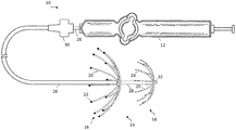
本開示のこれら及び他の態様を例示することを助けるために、図1に示された実施形態は、制御ハンドル12を備えた近位端と、二重ノードマルチレイ電極アセンブリ14を備えた遠位端とを有するカテーテル10を特長とする。二重ノードマルチレイ電極アセンブリ14は、それぞれが、複数のスパイン20を有する、近位マルチレイアレイ16と、遠位マルチレイアレイ18とを含むことができる。近位マルチレイアレイ16の各スパイン20は、1つ又は2つ以上のアブレーション電極22を有することができ、アブレーション電極22は、これらのスパインに沿う位置に応じて、カップ又はリング電極として構成されてもよい。同様に、遠位マルチレイアレイ18の少なくとも1つのスパイン20は、1つ又は2つ以上の診断電極24を有することができ、診断電極24も、必要に応じてカップ又はリング電極として構成されてもよい。図示された実施形態において、遠位マルチレイアレイ18の各スパイン20は、1つ又は2つ以上の診断電極24を有してもよい。近位マルチレイアレイ16と遠位マルチレイアレイ18との間の相対的な距離の調節を可能にするために、近位マルチレイアレイ16は、内側管状部材26の上に摺動可能に配設された外側管状部材24の遠位端に固定されてもよい。制御ハンドル12は、内側管状部材26に固定されてもよく、アクチュエータ30は、外側管状部材26の近位端に固定されてもよく、これにより、制御ハンドル12及びアクチュエータ30を互いに対して長手方向に摺動させるように操作することによって、電気生理学者は、近位マルチレイアレイ16と遠位マルチレイアレイ18との間の距離を、カテーテル10の遠位端で制御することができる。いくつかの実施形態では、二重ノードマルチレイ電極アセンブリ14は、遠位マルチレイアレイ18に位置するセンサ32などの、1つ又は2つ以上の単コイル又はマルチコイル位置センサを含んでもよい。以下に記載されるように、このような位置センサは、患者内の二重ノードマルチレイ電極アセンブリ14の位置及び/又は配向を判定する助けとなるよう使用されてもよい。近位マルチレイアレイ16の相対的な位置は、アクチュエータ30と制御ハンドル12との間の関係から判定されてもよく、又は近位マルチレイアレイ16にはまた、所望通りに位置センサ単数又は複数)が装着されてもよい。
To help illustrate these and other aspects of the present disclosure, the embodiment shown in FIG. 1 includes a proximal end with a
内側管状部材28及び外側管状部材26は、カテーテル本体を構成し得、それぞれは、単一の軸方向又は中央内腔を備えた細長い構造を特長とし得るが、任意に、所望に応じて複数の内腔を有することができる。特に、外側管状部材26は、中に内側管状部材が同軸状に配設される中央内腔を有してもよい。内側管状部材28はまた、潅注液を供給するため、並びに電極22及び/若しくは24、位置センサ32、他のセンサに関連するケーブル配線及び/若しくはリード線を迂回させるため、又は任意の他の好適な目的のためなどの、任意の好適な目的のための1つ又は2つ以上の内腔を特長としてもよい。
Inner
近位マルチレイアレイ16及び遠位マルチレイアレイ18を形成するスパイン20の数は、同一であっても又は異なってもよく、約5〜12の範囲であっても又は任意の他の好適な数であってもよい。スパイン20は、径方向に均一に又は不均一に分布してもよい。更に、各スパイン20は、複数の電極22又は24を含んでもよい。アブレーション電極22については、スパイン当たりの各電極は、所望通りに独立して制御されてもよい。使用される電極の数に応じて、これらは、スパインに沿って均一に分布してもよく、又は測定された電気信号及び/若しくは組織のアブレーションの分析を容易にするために、近位に、中心に若しくは遠位に偏っていてもよい。
The number of
内側管状部材28及び外側管状部材26は可撓性を有する、すなわち屈曲可能であるが、それらの長さに沿っては実質的に非圧縮性である。管状部材は、任意の好適な構造のものでよく、任意の好適な材料で作製することができる。他の構造は、ポリウレタン又はPEBAX(登録商標)(ポリエーテルブロックアミド)で作製された外壁を備える。外壁は、捩り剛性を増加させるために、ステンレス鋼又は同等物の埋込編組網を含み、これにより、近位端の回転は、遠位端の対応する回転に変換されて、二重ノードマルチレイ電極アセンブリ14の誘導及び位置付けを容易にする。外側管状部材26の外径は重要ではないが、一般に可能な限り小さくあるべきであり、所望の用途に応じて約3ミリメートル(10フレンチ)以下であり得る。同様に、管状部材の外壁の厚さも重要ではないが、内腔がプーラワイヤ、リードワイヤ、センサケーブル、及び任意の他のワイヤ、ケーブル、又はチューブを収容することができるように十分に薄いものであり得る。所望に応じて、一方又は両方の外壁の内表面は、補剛チューブ(図示せず)で裏張りされて、捩り安定性の改善を提供してもよい。本発明に関連した使用に好適なカテーテル本体構造の例は、米国特許第6,064,905号に記載及び図示されており、その全開示内容が、参照により本明細書に援用される。
Inner
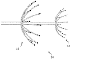
一態様では、スパイン20は、二重ノードマルチレイ電極アセンブリ14を安定化させるために、近位マルチレイアレイ16の電極22を、血管の小孔を形成する組織と接触させるか又はこれとより近接させるための、及び遠位マルチレイアレイ18を血管の内径に係合させるための拡張した配置を呈することを容易にする、以下に記載される形状記憶材料などの材料を含んでもよい。とりわけ、図1に示すように、一実施形態において、近位マルチレイアレイ16及び遠位マルチレイアレイ18のスパイン20は、これらが近位方向に湾曲する弧を形成する、予備成形された構成を有することができる。理解されるように、予備成形された構成に関連する弾力性は、電極22及び/又は24を周辺組織と接触させることを容易にすることができる。
In one aspect, the
スパイン20の例示的な構造は、電極22及び/又は24のうちの1つ又は2つ以上が上に装着されている、非伝導性被覆物を備えた可撓性ワイヤ又は他の構造的支柱を含んでもよい。一実施形態では、可撓性ワイヤは、拡張した配置と折り畳まれた配置との間の移行を容易にするために形状記憶材料から形成されてもよく、非伝導性被覆物はそれぞれ、ポリウレタン又はポリイミド管類などの生体適合性プラスチック管類を含んでもよい。例えば、ニチノールとして知られているニッケル−チタン合金が使用されてもよい。体温で、ニチノール製ワイヤは可撓性及び弾性であり、大抵の金属のように、ニチノール製ワイヤは、最小限の力を受けると変形し、その力の不在下ではそれらの形状に戻る。
An exemplary structure of the
ニチノールは、ニチノールがその温度相に依存する「記憶形状」を有するのを可能にする形状記憶及び超弾性を含む、可撓性及び弾性を超える興味深い機械特性を有する形状記憶合金(SMA)と呼ばれる材料の群に属する。オーステナイト相は、単純な立方結晶構造を持つニチノールのより強力でより高温の相である。超弾性挙動は、この相(50〜60℃の温度の広がりにわたって)で生じる。対応して、マルテンサイト相は、双晶構造を持つ比較的脆弱なより低温の相である。ニチノール材料がマルテンサイト相にあるとき、それは比較的容易に変形し、変形した状態に留まる。しかしながら、そのオーステナイト移行温度を超えて加熱されると、ニチノール材料は、その変形前形状に戻り、「形状記憶」効果をもたらす。ニチノールが加熱時にオーステナイトに転換し始める温度は、「As」温度と称される。ニチノールが加熱時にオーステナイトに転換し終えた温度は、「Af」温度と称される。 Nitinol is referred to as a shape memory alloy (SMA) with interesting mechanical properties beyond flexibility and elasticity, including shape memory and superelasticity that allows Nitinol to have a “memory shape” that depends on its temperature phase Belongs to a group of materials. The austenite phase is the stronger and hotter phase of nitinol with a simple cubic crystal structure. Superelastic behavior occurs in this phase (over a temperature spread of 50-60 ° C.). Correspondingly, the martensite phase is a relatively brittle lower temperature phase with a twin structure. When the nitinol material is in the martensite phase, it deforms relatively easily and remains in the deformed state. However, when heated above its austenite transition temperature, the nitinol material returns to its pre-deformation shape, resulting in a “shape memory” effect. The temperature at which nitinol begins to convert to austenite upon heating is referred to as the “As” temperature. The temperature at which nitinol has been converted to austenite upon heating is referred to as the “Af” temperature.
したがって、二重ノードマルチレイ電極アセンブリ14は、ガイディングシース内に送給されるように容易に折り畳まれ、その後、ガイディングシースが取り除かれた後に患者の所望の領域に送達されると、その拡張した形状記憶構成に容易に戻され得る、3次元形状を有することができる。あるいは、いくつかの実施形態では、二重ノードマルチレイ電極アセンブリ14の径方向の拡張を可能にするのに十分に剛性の非伝導性材料が非伝導性被覆物に使用される場合、スパインが電極の装着のためにその表面の少なくとも一部にわたって非伝導性の外側表面を有する限り、スパイン20が内部可撓性ワイヤなしで設計されてもよい。
Thus, when the dual node
スパインが遠位方向に湾曲する、図2に示されるようなスパイン20の他の構成が用いられてもよい。この実施形態では、近位マルチレイアレイ16は、複数のアブレーション電極22を有するスパイン20を用いる。あるいは、近位マルチレイアレイ16及び遠位マルチレイアレイ18のスパイン20は、それぞれ反対の方向のいずれの組み合わせで湾曲してもよい。それらの湾曲の配向とは無関係に、スパイン20は、患者の解剖学的構造に応じて、応じた適切なサイズにされてもよい。例えば、近位マルチレイアレイ16のスパイン20は、血管の小孔を形成する組織に係合するように構成された長さ及び/又は曲率を有することができ、一方で遠位マルチレイアレイ18のスパイン20は、血管の内径に係合する拡張した構成を形成するように適合させた長さ及び/又は曲率を有することができる。いくつかの実施形態では、遠位マルチレイアレイ18の拡張した構成によって呈される外径は、近位マルチレイアレイ16によって呈される外径よりも比較的小さい場合がある。
Other configurations of the
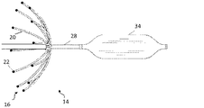
上に示したように、本開示はまた、二重ノードマルチレイ電極アセンブリ14が上述のものと同様の近位マルチレイアレイ16を用いるが、遠位マルチレイアレイ18が異なる拡張可と置き換えられてもよい、実施形態も含む。
As indicated above, the present disclosure also provides that the dual node
例えば、図3は、遠位ノードが膨張可能なバルーン34を用いて実装される実施形態を概略的に例示する。バルーン34は、血管形成処置又はステント配備に関連するものなどの、任意の好適な構造を用いてもよい。その拡張していない折り畳まれた構成において、バルーン34は、内側管状部材28の外径にぴったりと適合することができる。患者の血管内の所望の場所に位置付けられると、バルーン34は、二重ノードマルチレイ電極アセンブリ14を安定化する助けとなるために、それが血管の内径に係合する拡張した構成を呈するまで、例えば好適な膨張流体の使用によって、膨張され得る。
For example, FIG. 3 schematically illustrates an embodiment in which the distal node is implemented using an
別の例では、図4は、二重ノードマルチレイ電極アセンブリ14の遠位ノードが、ステント36、又は他の同様の拡張可能な腔内装置を用いて実装される、実施形態を概略的に例示する。ステント36は、内側管状部材28の外径にぴったりと適合する拡張していない折り畳まれた構成を有することができる。同様に、ステント36は、患者の血管内の所望の場所に位置付けられると、当業者に既知の任意の技法を用いて拡張することができる。その拡張した構成では、ステント36は、血管の内径に係合し、これによって、二重ノードマルチレイ電極アセンブリ14を安定化させることができる。
In another example, FIG. 4 schematically illustrates an embodiment in which the distal node of the dual-node
更に別の例が、図5に概略的に示されている。この実施形態では、二重ノードマルチレイ電極アセンブリ14の遠位ノードは、バスケット形状の電極アセンブリ38として構成される。バスケットアセンブリ38は、その近位端及び遠位端において接続された複数のスパイン40を有する。バスケット形状の電極アセンブリ38は、スパイン40が径方向外向きに弓状に曲がっている拡張した配置と、スパイン40がカテーテル本体の軸線に概ね沿って配置されている折り畳まれた配置とを有する。いくつかの実施形態では、バスケット形状の電極アセンブリ38の近位端と遠位端との間の距離は、例えば、プーラワイヤ42を近位に移動させ、スパイン40が拡張した構成へと外向きに弓状に曲がるようにすることによって、短くされてもよい。
Yet another example is shown schematically in FIG. In this embodiment, the distal node of the dual node
あるいは、スパイン40の構造は、バスケット形状の電極アセンブリ38が、例えば、内側管状部材28から出て進められることによってなどで、拘束されていないときにその拡張した構成を呈するようにし得る、形状記憶材料の使用に関して、スパイン20の構造と同様であってもよい。所望通りに、スパイン40はまた、バスケット形状の電極アセンブリ38が配備されるとき、血管内からの電気信号を測定するために、1つ又は2つ以上の診断電極44を支持してもよい。バスケット形状の電極アセンブリ38が、その拡張した構成を呈するとき、スパイン40は、血管の内径に係合し、これによって、二重ノードマルチレイ電極アセンブリ14を安定化させることができる。
Alternatively, the structure of the
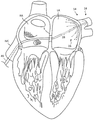
一態様では、電気生理学医は、当該技術分野において一般に知られているように、ガイディングシース、ガイドワイヤ及び拡張器を患者内に導入してもよい。本発明のカテーテルに関連する使用に好適なガイディングシースの例は、PREFACE(商標)編組ガイディングシース(Biosense Webster,Inc.(Diamond Bar,CA)から市販されている)及びDiRex(商標)ガイディングシース(BARD(Murray Hill,NJ)から市販されている)である。ガイドワイヤが挿入され、拡張器が取り除かれ、カテーテルがガイディングシースを通して導入され、それにより拡張器内のガイドワイヤ内腔は、カテーテルがガイドワイヤの上を通過するのを可能にする。図3に示される1つの例示的な手順では、ガイディングシース46内に配設されたカテーテル10は、下大静脈(IVC)を介して右心房(RA)に最初に導入され、そこでカテーテル10は左心房(LA)に到達するために心房中隔(S)を通過する。
In one aspect, the electrophysiologist may introduce a guiding sheath, guidewire, and dilator into the patient, as is generally known in the art. Examples of suitable guiding sheaths for use in connection with the catheters of the present invention include PREFACE ™ braided guiding sheaths (commercially available from Biosense Webster, Inc. (Diamond Bar, Calif.)) And DiRex ™ guys. Ding sheath (commercially available from BARD (Murray Hill, NJ)). The guide wire is inserted, the dilator is removed, and the catheter is introduced through the guiding sheath, so that the guide wire lumen within the dilator allows the catheter to pass over the guide wire. In one exemplary procedure shown in FIG. 3, the
理解されるように、ガイディングシース46は、折り畳まれた位置にある二重ノードマルチレイ電極アセンブリ14のスパイン20を被覆し、それにより、カテーテル全体が患者の脈管系を通過して所望の場所に至り得る。カテーテルの遠位端が所望の場所、例えば肺静脈に隣接する左心房に到達すると、ガイディングシースは引き抜かれて二重ノードマルチレイ電極アセンブリ14が露出される。ガイディングシースが引き抜かれると、スパイン20が外向きに屈曲してその拡張した構成を呈し、これにより、遠位マルチレイアレイ18は、血管の内径(仮想線で示す)に係合し、近位マルチレイアレイ16は、1つ又は2つ以上のアブレーション電極22を所望の領域で組織と接触させることができる。
As will be appreciated, the guiding
一態様では、複数の電極22は、血管、例えば、肺静脈の小孔の周囲の円周方向経路で接触することができる。別の態様では、実施形態は、例えば、上で又は他の箇所で論じられた技法を用いることによって、近位ノードと遠位ノードとの間の相対的な距離の調節を可能にしてもよい。対応して、アクチュエータ30及び制御ハンドル12の操作は、内側管状部材28及び外側管状部材26を通しての近位マルチレイアレイ16及び遠位マルチレイアレイ18の相対的な位置に対する制御を提供する。
In one aspect, the plurality of
理解されるように、本開示の技法と共に二重ノードマルチレイ電極アセンブリを用いる手順は、近位ノード及び遠位ノードのうちの一方又は両方を拡張する若しくは拡張させること、近位ノードと遠位ノードとの間の相対的な位置決めを調節すること、電気信号を記録すること、並びにアブレーションのためのエネルギーを送達すること、が含まれるがこれらに限定されない任意の所望の一連の動作が実行されることを可能にする。例示のように、1つ又は2つ以上の非限定的な態様は、遠位ノードを血管内に配備してアンカーとして機能させることと、近位ノードの相対的な長手方向位置を調節して、1つ又は2つ以上の電極を、血管の小孔の周囲の円周方向経路上で組織と所望の程度に接触させることと、を伴ってもよい。対応して、血管内壁の周囲の円周方向経路において組織をアブレーションするために、RFエネルギーが送達されてもよい。用いられているスパイン20の数及び電極の数に応じて、いくつかの実施形態では、実質的に完全な円周方向損傷部位が同時に形成されてもよい。
As will be appreciated, the procedure of using a dual node multi-lay electrode assembly with the techniques of this disclosure can expand or expand one or both of the proximal node and the distal node, the proximal node and the distal node. Any desired sequence of operations is performed including, but not limited to, adjusting the relative positioning with the node, recording electrical signals, and delivering energy for ablation. Makes it possible to As illustrated, one or more non-limiting aspects include deploying the distal node within the blood vessel to function as an anchor and adjusting the relative longitudinal position of the proximal node. One or more electrodes may involve contacting the tissue to a desired degree on a circumferential path around the vessel ostium. Correspondingly, RF energy may be delivered to ablate tissue in a circumferential path around the inner vessel wall. Depending on the number of
他の実施形態では、カテーテル10は、損傷部位の第1のセットが形成された後に回転されてもよく、これにより、電極20は、円周方向経路に沿って組織の新しい領域と接触し、アブレーションエネルギーの送達が次いで繰り返されてもよい。一連の回転及びエネルギーの送達は、必要に応じて繰り返されてもよい。血管の円周方向に周りの実質的に完全な損傷部位の形成は、上で述べた異常な信号の発生源を電気的に隔離することができる。
In other embodiments, the
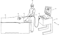
二重ノードマルチレイ電極アセンブリ14の使用を例示することを助けるために、図7は、本発明の実施形態による、侵襲的医療処置の概略図である。二重ノードマルチレイ電極アセンブリ14(この図には示されていない)を遠位端に有するカテーテル10は、それらが検出する信号を記録して分析するためのコンソール62に、電極及びセンサ(この図には示されていない)のリード線を連結するためのコネクタ60を近位端に有してもよい。電気生理学者64は、遠位マルチレイアレイ18の電極24を介してなど、患者の心臓68からの電極電位信号を取得するために、カテーテル10を患者66内に挿入することができる。電気生理学者64は、挿入を行うために、カテーテルに取り付けられた制御ハンドル12を使用する。
To help illustrate the use of the dual node
コンソール62は、受信された信号を分析し、コンソールに取り付けられたディスプレイ72上に分析の結果を提示することができる処理ユニット70を含むことができる。この結果は、典型的には、信号に由来するマップ、数値表示、及び/又はグラフの形態である。処理ユニット70は、1つ又は2つ以上の損傷部位を作り出すための近位マルチレイアレイ16の電極20へのエネルギーの送達を制御することもできる。電気生理学者64は、実質的に完全な円周方向損傷部位を作り出すために、上で述べた動作を実行することができる。
The
更に、処理ユニット70は、センサ32(この図では示されない)などの位置センサから信号を受信することも可能である。述べたように、センサ(複数可)はそれぞれ、1つの磁界応答性コイル又は複数のかかるコイルを備えてもよい。複数のコイルの使用は、6次元位置及び配向座標の判定を可能にする。したがって、センサは、外部コイルからの磁界に応答して電気位置信号を生成して、それによりプロセッサ70が心臓腔内におけるカテーテル10の遠位端の位置(例えば、場所及び配向)を可能にしてもよい。その後、電気生理学者は、ディスプレイ72上の患者の心臓の画像上で二重ノードマルチレイ電極アセンブリ14の位置を見てもよい。例として、この位置検知方法は、Biosense Webster Inc.(Diamond Bar,Calif.)により製造されるCARTO(商標)システムを使用して実装されてもよく、米国特許第5,391,199号、同第6,690,963号、同第6,484,118号、同第6,239,724号、同第6,618,612号、及び同第6,332,089号、PCT特許公開第96/05768号、並びに米国特許出願公開第2002/0065455A1号、同第2003/0120150A1号、及び同第2004/0068178A1号(これらの開示はすべて参照により本明細書に援用される)に詳細に記載されている。理解されるように、他の場所検知技法がまた用いられてもよい。一態様では、近位センサに対する遠位センサの座標が判定され、二重ノードマルチレイ電極アセンブリ14の構成に関連する他の既知の情報と共に、電極22及び/又は24のそれぞれの位置を見つけるために使用されてもよい。
Furthermore, the processing unit 70 can also receive signals from position sensors such as the sensor 32 (not shown in this figure). As stated, each sensor (s) may comprise one magnetic field responsive coil or a plurality of such coils. The use of multiple coils allows determination of 6-dimensional position and orientation coordinates. Thus, the sensor generates an electrical position signal in response to a magnetic field from the external coil, thereby enabling the processor 70 to position (eg, location and orientation) of the distal end of the
上記の説明は、本発明の現在開示されている実施形態を参照して提示したものである。本発明が属する技術分野の専門家であれば、本発明の原理、趣旨、及び範囲を有意に逸脱することなく、説明された構造に改変及び変更が実施されてもよいことを理解するであろう。当業者には理解されるように、図面は必ずしも縮尺通りではない。したがって、上記の説明は、添付の図面に記載及び例示される精密な構造のみに関連するものとして読まれるべきではなく、むしろ以下の最も完全で公正な範囲を有するとされる特許請求の範囲と一致し、かつそれらを補助するものとして読まれるべきである。 The above description has been presented with reference to presently disclosed embodiments of the present invention. Those skilled in the art to which the present invention pertains will understand that modifications and changes may be made to the described structure without significantly departing from the principles, spirit, and scope of the present invention. Let's go. As will be appreciated by those skilled in the art, the drawings are not necessarily to scale. Accordingly, the above description should not be read as referring only to the precise structure described and illustrated in the accompanying drawings, but rather has the most complete and fair scope as It should be read as a match and to assist them.
〔実施の態様〕
(1) 近位端及び遠位端を有する細長いカテーテル本体と、前記カテーテル本体の前記遠位端における二重ノードマルチレイ電極アセンブリとを備えたカテーテルであって、前記二重ノードマルチレイ電極アセンブリが、一端で接続された複数のスパインを備えたマルチレイアレイを含む近位ノードであって、各スパインが少なくとも1つのアブレーション電極を有する、近位ノードと、ステントを含む遠位ノードとを備え、前記二重ノードマルチレイ電極アセンブリが、拡張した構成と折り畳まれた構成とを有し、前記折り畳まれた構成において、前記近位マルチレイアレイの前記スパインが、前記カテーテル本体の長手方向軸線に概ね沿って配置され、前記遠位ノードが、前記折り畳まれた構成において、前記カテーテル本体に適合する、カテーテル。
(2) 前記遠位ノードが、前記拡張した構成において、血管内に配備されるように構成され、前記近位マルチレイアレイが、前記拡張した構成において、前記血管の小孔の組織を前記アブレーション電極のうちの少なくとも1つと係合させるように構成されている、実施態様1に記載のカテーテル。
(3) 前記細長いカテーテル本体が、外側管状部材の内腔内に摺動可能に配設された内側管状部材を備え、前記近位マルチレイアレイが、前記外側管状部材の遠位端に固定され、前記遠位ノードが、前記内側管状部材の遠位端に固定されている、実施態様1に記載のカテーテル。
(4) 前記内側管状部材及び前記外側管状部材の相対的な長手方向移動が、前記近位マルチレイアレイと前記遠位ノードとの間の距離を調節する、実施態様3に記載のカテーテル。
(5) 前記近位マルチレイアレイの各スパインが、複数の独立して制御されるアブレーション電極を備える、実施態様1に記載のカテーテル。
Embodiment
(1) A catheter comprising an elongated catheter body having a proximal end and a distal end, and a dual node multi-lay electrode assembly at the distal end of the catheter body, the double node multi-lay electrode assembly A proximal node comprising a multi-lay array with a plurality of spines connected at one end, each spine having at least one ablation electrode and a distal node comprising a stent The dual-node multi-lay electrode assembly has an expanded configuration and a collapsed configuration, wherein the spine of the proximal multi-lay array is in a longitudinal axis of the catheter body. Disposed generally along the distal node fits the catheter body in the folded configuration ,catheter.
(2) The distal node is configured to be deployed within a blood vessel in the expanded configuration, and the proximal multi-lay array is configured to ablate tissue in the vascular stoma in the expanded configuration. The catheter of embodiment 1, wherein the catheter is configured to engage with at least one of the electrodes.
(3) The elongate catheter body includes an inner tubular member slidably disposed within a lumen of the outer tubular member, and the proximal multi-ray array is fixed to a distal end of the outer tubular member. The catheter of embodiment 1, wherein the distal node is secured to a distal end of the inner tubular member.
4. The catheter of embodiment 3, wherein the relative longitudinal movement of the inner tubular member and the outer tubular member adjusts the distance between the proximal multi-lay array and the distal node.
5. The catheter of embodiment 1, wherein each spine of the proximal multi-lay array comprises a plurality of independently controlled ablation electrodes.
(6) 前記近位マルチレイアレイの前記スパインが、前記拡張した構成において、径方向外向きに湾曲する、実施態様1に記載のカテーテル。
(7) 前記近位マルチレイアレイの前記スパインが、近位に湾曲する、実施態様6に記載のカテーテル。
(8) 前記近位マルチレイアレイの前記スパインが、遠位に湾曲する、実施態様6に記載のカテーテル。
(9) 治療方法であって、
近位端及び遠位端を有する細長いカテーテル本体と、前記カテーテル本体の前記遠位端における二重ノードマルチレイ電極アセンブリとを備えたカテーテルを提供することであって、前記二重ノードマルチレイ電極アセンブリが、一端で接続された複数のスパインを備えたマルチレイアレイを含む近位ノードであって、各スパインが少なくとも1つのアブレーション電極を有する、近位ノードと、ステントを含む遠位ノードとを備え、前記二重ノードマルチレイ電極アセンブリが、拡張した構成と折り畳まれた構成とを有し、前記折り畳まれた構成において、前記近位マルチレイアレイの前記スパインが、前記カテーテル本体の長手方向軸線に概ね沿って配置され、前記遠位ノードが、前記折り畳まれた構成において、前記カテーテル本体に適合する、提供することと、
前記カテーテルの前記遠位端を心臓の所望の領域に位置付けることと、
前記ステントを、前記拡張した構成で血管内に配備して、前記血管の内径に係合させることと、
少なくとも1つのアブレーション電極を、前記血管の小孔を形成する組織と接触させるように、前記近位マルチレイアレイを位置付けることと、を含む、方法。
(10) 高周波エネルギーを前記アブレーション電極に送達して、損傷部位を形成することを更に含む、実施態様9に記載の方法。
(6) The catheter according to embodiment 1, wherein the spines of the proximal multi-lay array are curved radially outward in the expanded configuration.
(7) The catheter of embodiment 6, wherein the spine of the proximal multi-lay array is curved proximally.
8. The catheter of embodiment 6, wherein the spine of the proximal multi-lay array is curved distally.
(9) A treatment method,
Providing a catheter comprising an elongated catheter body having a proximal end and a distal end, and a dual node multi-lay electrode assembly at the distal end of the catheter body, the double node multi-lay electrode A proximal node comprising a multi-lay array with a plurality of spines connected at one end, each spine having at least one ablation electrode; and a distal node comprising a stent. The dual node multi-lay electrode assembly has an expanded configuration and a collapsed configuration, wherein the spine of the proximal multi-lay array has a longitudinal axis of the catheter body. And the distal node is disposed on the catheter body in the folded configuration. And that if, to provide,
Positioning the distal end of the catheter in a desired region of the heart;
Deploying the stent in a blood vessel in the expanded configuration and engaging the inner diameter of the blood vessel;
Positioning the proximal multi-lay array such that at least one ablation electrode is in contact with tissue forming the ostium of the blood vessel.
10. The method of embodiment 9, further comprising delivering radio frequency energy to the ablation electrode to form a damaged site.
(11) 損傷部位を、前記血管の前記小孔の周囲の円周方向経路内に形成することを更に含む、実施態様10に記載の方法。
(12) 前記近位マルチレイアレイと前記遠位ノードとの間の相対的な距離を調節することを更に含む、実施態様9に記載の方法。
(13) 前記近位マルチレイアレイと前記遠位ノードとの間の前記相対的な距離を調節することが、前記遠位ノードを前記血管内に係留させ、前記近位マルチレイアレイを前記遠位ノードに向かって進めて、前記少なくとも1つのアブレーション電極を前記小孔の組織と接触させることを含む、実施態様12に記載の方法。
11. The method of
The method of claim 9, further comprising adjusting a relative distance between the proximal multi-lay array and the distal node.
(13) Adjusting the relative distance between the proximal multi-lay array and the distal node anchors the distal node in the blood vessel and causes the proximal multi-ray array to move to the far node. 13. The method of
Claims (8)
Applications Claiming Priority (2)
| Application Number | Priority Date | Filing Date | Title |
|---|---|---|---|
| US14/964,298 US10524857B2 (en) | 2015-09-14 | 2015-12-09 | Dual node multiray electrode catheter |
| US14/964,298 | 2015-12-09 |
Publications (1)
| Publication Number | Publication Date |
|---|---|
| JP2017104546A true JP2017104546A (en) | 2017-06-15 |
Family
ID=57530559
Family Applications (1)
| Application Number | Title | Priority Date | Filing Date |
|---|---|---|---|
| JP2016238251A Pending JP2017104546A (en) | 2015-12-09 | 2016-12-08 | Dual node multiray electrode catheter |
Country Status (5)
| Country | Link |
|---|---|
| EP (1) | EP3178383A1 (en) |
| JP (1) | JP2017104546A (en) |
| CN (1) | CN106852705A (en) |
| AU (1) | AU2016259312A1 (en) |
| CA (1) | CA2949974A1 (en) |
Families Citing this family (3)
| Publication number | Priority date | Publication date | Assignee | Title |
|---|---|---|---|---|
| CN113729928B (en) * | 2020-05-29 | 2023-03-07 | 先健科技(深圳)有限公司 | Ablation device |
| CN113081240B (en) * | 2021-03-31 | 2022-03-01 | 上海睿刀医疗科技有限公司 | Cage-shaped electrode catheter and ablation device comprising same |
| CN114404035B (en) * | 2022-01-21 | 2024-08-16 | 杭州德诺电生理医疗科技有限公司 | Ablation device |
Citations (4)
| Publication number | Priority date | Publication date | Assignee | Title |
|---|---|---|---|---|
| US6652517B1 (en) * | 2000-04-25 | 2003-11-25 | Uab Research Foundation | Ablation catheter, system, and method of use thereof |
| JP2012525933A (en) * | 2009-05-07 | 2012-10-25 | セント・ジュード・メディカル・インコーポレーテッド | Irrigated ablation catheter with multi-segment ablation electrode |
| US20130103027A1 (en) * | 2010-05-05 | 2013-04-25 | Martin J. Sklar | Anchored cardiac ablation catheter |
| JP2014133132A (en) * | 2013-01-08 | 2014-07-24 | Biosense Webster (Israel) Ltd | Catheter including multi-spine with different length disposed in one or more distal assembly |
Family Cites Families (16)
| Publication number | Priority date | Publication date | Assignee | Title |
|---|---|---|---|---|
| US5772590A (en) | 1992-06-30 | 1998-06-30 | Cordis Webster, Inc. | Cardiovascular catheter with laterally stable basket-shaped electrode array with puller wire |
| WO1996005768A1 (en) | 1994-08-19 | 1996-02-29 | Biosense, Inc. | Medical diagnosis, treatment and imaging systems |
| US5391199A (en) | 1993-07-20 | 1995-02-21 | Biosense, Inc. | Apparatus and method for treating cardiac arrhythmias |
| US6690963B2 (en) | 1995-01-24 | 2004-02-10 | Biosense, Inc. | System for determining the location and orientation of an invasive medical instrument |
| JP4072587B2 (en) | 1996-02-15 | 2008-04-09 | バイオセンス・ウェブスター・インコーポレイテッド | Independently positionable transducer for position determination system |
| IL125757A (en) | 1996-02-15 | 2003-09-17 | Biosense Inc | Medical procedures and apparatus using intrabody probes |
| US6239724B1 (en) | 1997-12-30 | 2001-05-29 | Remon Medical Technologies, Ltd. | System and method for telemetrically providing intrabody spatial position |
| US6064905A (en) | 1998-06-18 | 2000-05-16 | Cordis Webster, Inc. | Multi-element tip electrode mapping catheter |
| US6484118B1 (en) | 2000-07-20 | 2002-11-19 | Biosense, Inc. | Electromagnetic position single axis system |
| US6748255B2 (en) | 2001-12-14 | 2004-06-08 | Biosense Webster, Inc. | Basket catheter with multiple location sensors |
| US6741878B2 (en) | 2001-12-14 | 2004-05-25 | Biosense Webster, Inc. | Basket catheter with improved expansion mechanism |
| US7729742B2 (en) | 2001-12-21 | 2010-06-01 | Biosense, Inc. | Wireless position sensor |
| US20040068178A1 (en) | 2002-09-17 | 2004-04-08 | Assaf Govari | High-gradient recursive locating system |
| US7416549B2 (en) * | 2003-10-10 | 2008-08-26 | Boston Scientific Scimed, Inc. | Multi-zone bipolar ablation probe assembly |
| WO2014022436A1 (en) * | 2012-07-30 | 2014-02-06 | Fractyl Laboratories Inc. | Electrical energy ablation systems, devices and methods for the treatment of tissue |
| CN103519889B (en) * | 2013-10-10 | 2016-02-24 | 迈德医疗科技(上海)有限公司 | A kind of radio frequency ablation electrode device of double-deck umbrella-shaped probes |
-
2016
- 2016-11-15 AU AU2016259312A patent/AU2016259312A1/en not_active Abandoned
- 2016-11-29 CA CA2949974A patent/CA2949974A1/en not_active Abandoned
- 2016-12-08 JP JP2016238251A patent/JP2017104546A/en active Pending
- 2016-12-08 EP EP16202870.8A patent/EP3178383A1/en not_active Withdrawn
- 2016-12-09 CN CN201611128395.9A patent/CN106852705A/en active Pending
Patent Citations (4)
| Publication number | Priority date | Publication date | Assignee | Title |
|---|---|---|---|---|
| US6652517B1 (en) * | 2000-04-25 | 2003-11-25 | Uab Research Foundation | Ablation catheter, system, and method of use thereof |
| JP2012525933A (en) * | 2009-05-07 | 2012-10-25 | セント・ジュード・メディカル・インコーポレーテッド | Irrigated ablation catheter with multi-segment ablation electrode |
| US20130103027A1 (en) * | 2010-05-05 | 2013-04-25 | Martin J. Sklar | Anchored cardiac ablation catheter |
| JP2014133132A (en) * | 2013-01-08 | 2014-07-24 | Biosense Webster (Israel) Ltd | Catheter including multi-spine with different length disposed in one or more distal assembly |
Also Published As
| Publication number | Publication date |
|---|---|
| CN106852705A (en) | 2017-06-16 |
| AU2016259312A1 (en) | 2017-06-29 |
| CA2949974A1 (en) | 2017-06-09 |
| EP3178383A1 (en) | 2017-06-14 |
Similar Documents
| Publication | Publication Date | Title |
|---|---|---|
| EP3178516B1 (en) | Stabilized spine electrophysiologic catheter | |
| US10517668B2 (en) | Dual node multiray electrode catheter | |
| EP3178385B1 (en) | Electrode array catheter with interconnected framework | |
| US9895073B2 (en) | Dual basket catheter | |
| EP3231358A1 (en) | Basket catheter with prestrained framework | |
| JP2017124159A (en) | Dual node multiray electrode catheter | |
| JP6890946B2 (en) | Lasso catheter with movable ablation needle | |
| JP6855209B2 (en) | Self-centering multi-ray ablation catheter | |
| JP2017104546A (en) | Dual node multiray electrode catheter | |
| US10524858B2 (en) | Dual node multiray electrode catheter |
Legal Events
| Date | Code | Title | Description |
|---|---|---|---|
| A621 | Written request for application examination |
Free format text: JAPANESE INTERMEDIATE CODE: A621 Effective date: 20191205 |
|
| A977 | Report on retrieval |
Free format text: JAPANESE INTERMEDIATE CODE: A971007 Effective date: 20201120 |
|
| A131 | Notification of reasons for refusal |
Free format text: JAPANESE INTERMEDIATE CODE: A131 Effective date: 20201201 |
|
| A02 | Decision of refusal |
Free format text: JAPANESE INTERMEDIATE CODE: A02 Effective date: 20210629 |