JP2017103677A - Control device - Google Patents
Control device Download PDFInfo
- Publication number
- JP2017103677A JP2017103677A JP2015236784A JP2015236784A JP2017103677A JP 2017103677 A JP2017103677 A JP 2017103677A JP 2015236784 A JP2015236784 A JP 2015236784A JP 2015236784 A JP2015236784 A JP 2015236784A JP 2017103677 A JP2017103677 A JP 2017103677A
- Authority
- JP
- Japan
- Prior art keywords
- unit
- safety
- data
- communication frame
- processing unit
- Prior art date
- Legal status (The legal status is an assumption and is not a legal conclusion. Google has not performed a legal analysis and makes no representation as to the accuracy of the status listed.)
- Granted
Links
Images


Abstract
Description
本発明の実施形態は、制御装置に関する。 Embodiments described herein relate generally to a control device.
従来より、プラント等を制御する制御システムは、社会基盤、産業基盤を支えるため24時間365日の連続運転できることが最重要要件とされている。このような制御システムは、悪意ある第三者からの攻撃等により稼働が阻害された場合、社会的な影響が非常に大きい。従来の制御システムはクローズドシステムで構成され、外部ネットワークと接続されていないため、悪意ある第三者からの攻撃等の脅威は殆ど意識されてこなかった。 Conventionally, the most important requirement for a control system for controlling a plant or the like is that it can be operated continuously for 24 hours 365 days in order to support a social infrastructure and an industrial infrastructure. Such a control system has a great social impact when operation is hindered by an attack from a malicious third party. Since the conventional control system is composed of a closed system and is not connected to an external network, threats such as attacks from malicious third parties have hardly been recognized.
しかしながら、近年、制御システムに汎用OSが採用されるようになり、外部ネットワークからのリモートコントロールができるようになるなど、システムの構成・使用状況に変化が生じてきている。そのため、制御システムで従来から求められている安全性(以下セーフティと称す)と、セキュリティとを両立した制御システムが望まれている。 However, in recent years, general-purpose OSs have been adopted for control systems, and changes have occurred in the system configuration and usage, such as remote control from an external network. Therefore, there is a demand for a control system that achieves both safety (hereinafter referred to as “safety”) that has been conventionally required in a control system and security.
本発明が解決しようとする課題は、制御装置におけるセキュリティ機能とセーフティ機能の両立を実現し、両機能をもたせた当該制御装置が制御するシステムのアベイラビリティの低減を回避することができる制御装置を提供することである。 A problem to be solved by the present invention is to provide a control device that realizes both security functions and safety functions in a control device and can avoid a reduction in the availability of a system controlled by the control device having both functions. It is to be.
実施形態の制御装置は、セキュリティ処理部と、セーフティデータ置換部と、セーフティ処理部を備える。セキュリティ処理部は、通信フレームの入出力を行う通信インタフェース部と、通信フレームの送受信に係る統計情報を管理する通信処理部と統計情報を基にサービス不能攻撃を監視する監視部と、を有する。セーフティデータ置換部は、監視部によりサービス不能攻撃が検出された場合に、受信した通信フレームに含まれる所定のデータに対する置換処理を実施すると判定する処理実施判定部と処理実施判定部で置換処理を実施すると判定された場合に、セキュリティ処理部から受信した通信フレームの所定のデータを健全であるとされる値に置換するデータ置換部と置換がなされた通信フレームの誤り検出符号を再計算し付与する符号計算・付与部とを有する。セーフティ処理部は、セーフティデータ置換部から受信した通信フレームの所定のデータから当該通信フレームの健全性を確認するセーフティデータ確認部と、セーフティデータ確認部によりセーフティデータ置換部から受信した通信フレームの健全性が確認された場合に、当該通信フレームのデータを基に配下の装置を制御するための制御値を算出する制御演算部と、配下の装置へ制御値を出力し、配下の装置からのデータを入力するI/Oデータ入出力部と、を有する。 The control device of the embodiment includes a security processing unit, a safety data replacement unit, and a safety processing unit. The security processing unit includes a communication interface unit that inputs and outputs communication frames, a communication processing unit that manages statistical information related to transmission and reception of communication frames, and a monitoring unit that monitors a denial of service attack based on the statistical information. The safety data replacement unit performs a replacement process with a process execution determination unit and a process execution determination unit that determine that a replacement process for predetermined data included in a received communication frame is to be performed when a monitoring unit detects a denial of service attack. When it is determined to be implemented, the data replacement unit that replaces predetermined data of the communication frame received from the security processing unit with a value that is considered sound and the error detection code of the replaced communication frame are recalculated and assigned A code calculation / assignment unit. The safety processing unit includes a safety data confirmation unit that confirms the soundness of the communication frame from predetermined data of the communication frame received from the safety data replacement unit, and a soundness of the communication frame received from the safety data replacement unit by the safety data confirmation unit. If the data is confirmed, the control operation unit calculates a control value for controlling the subordinate apparatus based on the data of the communication frame, and outputs the control value to the subordinate apparatus, and the data from the subordinate apparatus And an I / O data input / output unit.
(概要)
プラント等を制御する制御システムにおけるセーフティ機能とセキュリティ機能に関して、以下が知られている。
(Overview)
The following are known regarding safety functions and security functions in a control system for controlling a plant or the like.
セーフティの観点では、IEC61508「電気・電子・プログラマブル電子安全関連系の機能安全」が定められている。セーフティ機能を実現する代表的な手法の一つとして、ブラックチャネル通信と呼ばれる手法が確立されている。これは、送信側で通信フレーム(以下、フレームと記す)内に時刻情報やシーケンス番号など、フレーム毎に変化する値や、CRC(Cyclic Redundancy Check)などの誤り検出符号を付与し、受信側でそれらの情報の健全性を確認する手法である。上記フレーム毎に変化する値が一定の値から変化しない異常や、フレームの大幅な損失時など許容値以上の変化が生じる異常を、受信側で検出し、システムが安全側に遷移するようにする。 From the viewpoint of safety, IEC 61508 “Functional safety of electrical / electronic / programmable electronic safety-related systems” is defined. As one of the representative methods for realizing the safety function, a method called black channel communication has been established. This is because the transmission side adds a value that changes from frame to frame, such as time information and sequence number, and an error detection code such as CRC (Cyclic Redundancy Check) in the communication frame (hereinafter referred to as a frame). This is a method for confirming the soundness of such information. Detect abnormalities where the value that changes for each frame does not change from a certain value, or abnormalities that cause a change beyond the allowable value, such as when there is a significant loss of frames, so that the system transitions to the safe side .
一方、セキュリティの観点では、標準化規格の策定や評価・認証機関の整備等、制御システムセキュリティのための取り組みが本格化しつつあり、保護機能や開発プロセスを定めたIEC国際標準規格(IEC62443)が策定中である。セキュリティにおける代表的な攻撃手法としてパケット(フレーム)を攻撃対象に大量に送信し、通信障害を生じさせるDoS(Denial of Service)攻撃と呼ばれる攻撃手法が存在する。本攻撃への対応方法としては、例えば、受信したフレームの数を監視し、その数が一定値以上の値になった場合にはDoS攻撃を受けているとみなして受信を禁止し、DoS攻撃検出後は、一定間隔で受信したフレームの数を監視し、その数が閾値を下回った場合にDoS攻撃が収束したと判断して受信を許可するDoS攻撃対策がある。 On the other hand, in terms of security, efforts for control system security, such as the establishment of standardization standards and the establishment of evaluation / certification bodies, are becoming full-scale, and the IEC international standard (IEC62443) that defines protection functions and development processes has been established. It is in. As a typical attack method in security, there is an attack method called a DoS (Denial of Service) attack that causes a communication failure by transmitting a large amount of packets (frames) to an attack target. As a method for dealing with this attack, for example, the number of received frames is monitored, and if the number exceeds a certain value, it is considered that a DoS attack has occurred and reception is prohibited, and a DoS attack is performed. After the detection, there is a DoS attack countermeasure that monitors the number of frames received at regular intervals, and determines that the DoS attack has converged when the number falls below a threshold and permits reception.
しかしながら、上記のようなセーフティのためのブラックチャネル通信機能とセキュリティのためのDoS攻撃対策機能とを共に制御装置に実装した場合、以下の問題が生じる。 However, when both the black channel communication function for safety and the DoS attack countermeasure function for security are mounted on the control device, the following problems occur.
DoS攻撃対策機能によりDoS攻撃を検出し、フレームの受信を禁止する場合、DoS攻撃が収束するまでの間フレームは受信されない。このため、DoS攻撃の収束後、新たにフレームを受信したとき、受信したフレームに含まれるタイムスタンプやシーケンス番号の値の変化が許容範囲外となると、セーフティ機能により、システムが安全停止してしまう。つまり、制御装置にセーフティ機能とセキュリティ機能であるDoS攻撃対策機能を共存させた場合、DoS攻撃対策機能によりシステムのアベイラビリティが損なわれてしまう。 When a DoS attack is detected by the DoS attack countermeasure function and reception of a frame is prohibited, the frame is not received until the DoS attack converges. For this reason, when a new frame is received after convergence of the DoS attack, if the change in the value of the time stamp or sequence number included in the received frame is out of the allowable range, the system is safely stopped by the safety function. . That is, when a safety function and a DoS attack countermeasure function that is a security function coexist in the control device, the availability of the system is impaired by the DoS attack countermeasure function.
以下に説明する諸実施形態にかかる制御装置は、前段のセキュリティ機能を有する機能部と後段のセーフティ機能を有する機能部との間に、DoS攻撃等のサービス不能攻撃時にブラックチャネル通信におけるタイムスタンプやシーケンス番号の付け替え(置換)、誤り検出符号の再計算および付与をすることにより、セーフティ機能によってシステムが自動的に安全停止しないようにする機能部を設けている。これにより、以下に説明する制御装置は、セキュリティ機能とセーフティ機能の両立を実現し、当該制御装置が制御するシステムのアベイラビリティの低減を回避する。 The control apparatus according to the embodiments described below includes a time stamp in black channel communication between a functional unit having a security function in the former stage and a functional part having a safety function in the latter stage during a denial of service attack such as a DoS attack. A function unit is provided to prevent the system from being automatically stopped safely by the safety function by changing the sequence number (replacement), recalculating and adding the error detection code. Thus, the control device described below realizes both security functions and safety functions, and avoids reducing the availability of the system controlled by the control device.
(第1の実施形態)
はじめに、第1の実施形態にかかる制御装置について図1を用いて説明する。図1は、第1の実施形態にかかる制御装置の構成を示すブロック図である。
(First embodiment)
First, the control apparatus according to the first embodiment will be described with reference to FIG. FIG. 1 is a block diagram illustrating a configuration of a control device according to the first embodiment.
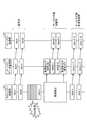
図1に示す制御装置100は、図示しない配下の装置を制御するとともに、上位装置に対して制御状態の通知等をする装置であり、セキュリティ処理部101、セーフティデータ置換部102、およびセーフティ処理部103の3つのブロックから構成される。これらは同一のハードウェア部品上に構成されてもよいし、別々のハードウェア部品上に構成されてもよい。
A
セキュリティ処理部101は、イーサネット(登録商標)等によるネットワークを介しフレームを送受信するためのインタフェースとなる通信I/F部104と、この通信I/F部104に接続され、受信したフレームを処理する通信処理部105と、通信処理部105に接続され、当該制御装置100におけるフレーム受信状況を監視する監視部106とを備える。
The
通信I/F部104は、上位装置などネットワーク上の他の装置からのフレームを受信し、通信処理部105へ受信したフレームを転送する。また、通信I/F部104は、通信処理部105からのデータ(フレーム)を上位装置などネットワーク上の他の装置に送信する。 The communication I / F unit 104 receives a frame from another device on the network such as a host device, and transfers the received frame to the communication processing unit 105. Further, the communication I / F unit 104 transmits data (frame) from the communication processing unit 105 to another device on the network such as a host device.
通信処理部105は、フレーム受信状況としてのフレーム受信数(受信したフレームの数)など、統計情報を管理する。また、通信処理部105は、監視部106により受信が許可されている場合、通信I/F部104からのフレームをセーフティデータ置換部102へ転送し、監視部106により受信が禁止されている場合、通信I/F部104からのフレームを破棄する。また、通信処理部105は、セーフティ処理部103からのフレームを通信I/F部104へ転送する。
The communication processing unit 105 manages statistical information such as the number of received frames (the number of received frames) as the frame reception status. Further, when reception is permitted by the monitoring unit 106, the communication processing unit 105 transfers a frame from the communication I / F unit 104 to the safety
監視部106は、上記のように通信処理部105で管理されるフレーム受信状況を監視し、フレームの受信の禁止/許可にかかる制御を行う。この監視部106の詳細については、後述する。 The monitoring unit 106 monitors the frame reception status managed by the communication processing unit 105 as described above, and performs control related to prohibition / permission of frame reception. Details of the monitoring unit 106 will be described later.
セーフティデータ置換部102は、セキュリティ処理部101の後段に接続される。このセーフティデータ置換部102は、前述の通信処理部105および監視部106からの情報(後述)が入力される処理実施判定部107と、処理実施判定部107に接続され、受信したフレームに含まれる健全性確認データ(所定のデータ)のセーフティヘッダの置換(後述)を行うデータ置換部108と、データ置換部108に接続され、健全性確認データに含まれる誤り検出符号(または誤り訂正符号)を、セーフティヘッダが置換されたフレームについて再計算しあらためて付与する符号計算・付与部109とを備える。
The safety
セーフティ処理部103は、セーフティデータ置換部102の後段に接続される。このセーフティ処理部103は、フレーム毎に変化する値をもつセーフティヘッダ、および誤り検出符号からなる安全性確認データを含むセーフティデータを生成しフレームに付与するセーフティデータ生成部110と、セーフティデータ置換部102からのデータの安全性を確認し、安全性が確認されたデータを制御演算部111へ転送するセーフティデータ確認部112と、セーフティデータ確認部112に接続され、図示しない配下の装置からのデータを処理しセーフティデータ生成部110に出力し、セーフティデータ確認部112からのデータを基に配下の装置に対する制御データ(制御値)を演算する制御演算部111と、制御演算部111からの制御データを配下の装置へ出力するとともに、配下の装置からのデータを制御演算部111へ出力するI/Oデータ入出力部113とを備える。なお、配下の装置からI/Oデータ入出力部113へ入力されたデータは、制御演算部111およびセーフティデータ生成部110を介し、セーフティデータ置換部102を経由することなく通信処理部105へ転送され、通信I/F部104を介して上位装置などへ送信される。
The
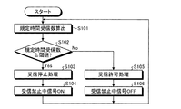
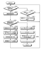
次に、上記構成による監視部106の動作の詳細について図2を用いて説明する。図2は、監視部106の動作フローを示すフローチャートである。 Next, details of the operation of the monitoring unit 106 configured as described above will be described with reference to FIG. FIG. 2 is a flowchart showing an operation flow of the monitoring unit 106.
監視部106は、定周期で通信処理部105が管理しているフレーム受信数を含む統計情報を取得し、この統計情報に含まれるフレーム受信数からその前回値と今回値の差分を計算し、規定時間内に受信したフレームの数(規定時間受信数)を算出する(S101)。 The monitoring unit 106 obtains statistical information including the number of received frames managed by the communication processing unit 105 at regular intervals, calculates a difference between the previous value and the current value from the number of received frames included in the statistical information, The number of frames received within the specified time (specified number of received times) is calculated (S101).
この算出値(規定時間受信数)が規定値(閾値)以上の場合(S102でYes)、サービス不能攻撃とみなし、監視部106は、通信処理部105に受信を停止するよう指令を出し(受信停止処理:S103)、さらに、セーフティデータ置換部102の処理実施判定部107に受信禁止中信号ONを伝達する(S104)。一方、上記算出値(規定時間受信数)が規定値(閾値)未満の場合(S102でNo)、監視部106は、通信処理部105に受信を許可する指令を出し(受信許可処理:S105)、セーフティデータ置換部102の処理実施判定部107に受信禁止中信号OFFを伝達する(S106)。
When the calculated value (number of receptions for the specified time) is equal to or greater than the specified value (threshold) (Yes in S102), it is regarded as a denial of service attack, and the monitoring unit 106 issues a command to the communication processing unit 105 to stop reception (reception) Stop processing: S103), and further, a reception prohibition signal ON is transmitted to the processing
このように、本実施形態では、セキュリティ処理部101により、DoS攻撃に代表されるサービス不能攻撃のような予め規定された許容値を超えた数のフレームを受信した場合には、強制的に受信を拒否する。そして、規定時間内に受信したフレームの数が規定値未満に収まった場合、監視部106は、サービス不能攻撃が収束したと判定し通信処理部105に再び受信を許可する。許可を受けた通信処理部105は、受信したフレームをセーフティデータ置換部102の処理実施判定部107に転送し、監視部106は、受信禁止中信号OFFを処理実施判定部107に伝達する。以上の処理を定周期で繰り返す。
As described above, in the present embodiment, when the
次に、セーフティデータ置換部102の動作(通常処理)について図3を用いて説明する。図3は、セーフティデータ置換部102の通常処理における動作フローを示すフローチャートである。
Next, the operation (normal process) of the safety
セーフティデータ置換部102の処理実施判定部107は、受信禁止中信号のON/OFFを判断し、OFFの場合(S201でNo)、セキュリティ処理部101から受信したフレームがあると(S206でYes)、このフレームをそのままセーフティ処理部103へ転送し(S207)、無い場合は(S206でNo)、S201に戻る。
The processing
一方、受信禁止中信号がONの場合は(S201でYes)、処理実施判定部107は、セーフティデータ置換部102からセーフティ処理部103へ前回送信したフレーム(前回出力フレーム)を採用し、この前回出力フレームをデータ置換部108に転送する(S202)。
On the other hand, when the reception prohibition signal is ON (Yes in S201), the processing
データ置換部108は、この前回出力フレームについて、そのセーフティヘッダを更新する置換(後述)を行う(S203)。
The
ここで、図4に、フレームフォーマットの一例を示す。同図に示すように、1つのフレームは、宛先アドレスと、送信元アドレスと、データのタイプを示すデータ識別情報と、データ本体とフレームの健全性を確認するための健全性確認データとからなるセーフティデータとを含んで構成される。健全性確認データ内には、シーケンス番号やタイムスタンプなど、フレーム毎に変化する値を含むセキュリティヘッダと、誤り検出符号(図4の例では、CRC)とが含まれる。なお、健全性確認データには、上記のシーケンス番号、タイムスタンプ、誤り検出符号のいずれかを含めるようにしてもよいし、全てを含めるようにしてもよい。 Here, FIG. 4 shows an example of the frame format. As shown in the figure, one frame is composed of a destination address, a transmission source address, data identification information indicating the type of data, and soundness confirmation data for confirming the soundness of the data body and the frame. It includes safety data. The soundness confirmation data includes a security header including a value that changes for each frame, such as a sequence number and a time stamp, and an error detection code (CRC in the example of FIG. 4). Note that the soundness confirmation data may include any one of the sequence numbers, time stamps, and error detection codes, or all of them.
データ置換部108は、図4に示したフレームに含まれる健全性確認データ内のシーケンス番号、タイムスタンプなどのセーフティヘッダを、後段のセーフティ処理部103においてセーフティヘッダの値の変化が許容範囲内と判断されるように別の値に置換する。置換する方法は、セーフティヘッダの前回値のインクリメントでもよいし、n倍などの算術計算に基づくものでもよい。
The
その後、符号計算・付与部109が、置換後のフレームを用いてこのフレームに対する誤り検出符号を再計算し、算出した符号を新しい誤り検出符号として上記置換後のフレームにあらためて付与し(S204)、セーフティ処理部103へ送信する(S205)。
Thereafter, the code calculation /
次に、セーフティ処理部103の動作について図5を用いて説明する。図5は、セーフティ処理部103の動作フローを示すフローチャートである。
Next, the operation of the
セーフティ処理部103では、セーフティデータ置換部102からフレームを受信すると、セーフティデータ確認部112が、受信したフレーム内の健全性確認データに含まれるセーフティヘッダ(シーケンス番号やタイムスタンプ)が前回値から更新されているか否かを確認し、更新されていなければエラーと判断し(S301でNo)、制御演算部111がシステムを安全停止させるための安全停止処理へ遷移する(S305)。そうでなければ、セーフティデータ確認部112は、処理をS302へ移行する。
When the
S302では、セーフティデータ確認部112によりセーフティヘッダの今回値と前回値との差分が許容値Xを超えているか否か確認し、超えていることが確認できた場合もエラーと判断し(S302でNo)、制御演算部111が安全停止処理へ遷移する(S305)。
In S302, the safety
一方、セーフティデータ確認部112によりセーフティヘッダの今回値と前回値との差分が許容値以下(正常範囲内)と確認された場合(S302でYes)、制御演算部111は、セーフティデータ置換部102から転送されてきたフレームのデータを採用し、配下の装置であるI/O(入力装置/出力装置)を制御するための制御値を演算し(制御値演算:S303)、この制御値をI/Oデータ入出力部113に出力させる(I/O出力:S304)。
On the other hand, when the safety
なお、本制御装置100によるシステムのアベイラビリティを、より考慮する構成として、上記許容値に加えリトライ回数を設けるようにしてもよい。この場合、セーフティデータ確認部112が上記のようにエラーと判定した場合にはそのときのフレームのデータを採用せずに前回セーフティ処理部103へ送信したフレームのデータを採用するとともに、エラー回数を保持するようにする。そして、セーフティデータ確認部112がリトライ回数分連続してエラーが生じたことを検出した場合に異常とみなし、制御演算部111に安全停止処理へ移行させることにより、上記のように許容値を超えると直ちに安全停止処理へ移行するよりも、システムのアベイラビリティが保たれる。
As a configuration that further considers system availability by the
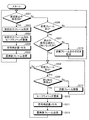
次に、サービス不能攻撃が収束した場合のセーフティデータ置換部102の動作について図6を用いて説明する。図6は、サービス不能攻撃が収束した場合のセーフティデータ置換部102の動作フローを示すフローチャートである。
Next, the operation of the safety
サービス不能攻撃中は先述のとおり、セーフティデータ置換部102が健全性確認データを置換したフレームを生成し、セーフティ処理部103へ伝送する。その後サービス不能攻撃が収束した際に、そのときのセーフティデータ置換部102がもつ健全性確認データと、新しく受信したフレームの健全性確認データの値に乖離が生じた場合、セーフティ処理部103により受信フレームが異常と判断されることが懸念される。
During the denial of service attack, as described above, the safety
こうした事態を避けるために、セーフティデータ置換部102の処理実施判定部107は、受信禁止中信号がONからOFFに変化したのを検出すると(S401)、前回、セーフティデータ置換部102からセーフティ処理部103へ送信したフレームのセーフティヘッダ(現セーフティヘッダ)をデータ置換部108から取得し(S402)、新規受信したフレームのセーフティヘッダ(新規受信セーフティヘッダ)を抽出する(S403)。そして、処理実施判定部107は、新規受信セーフティヘッダのデータ(例えば、シーケンス番号)と現セーフティヘッダのデータとの差分を算出する(S404)。その後、処理実施判定部107は、この差分の大小関係により、処理を分岐させる。
In order to avoid such a situation, when the processing
現セーフティヘッダの値(現出力値)より新規受信セーフティヘッダの値(新規受信値)の方が大きい場合で(S405でYes)上記差分が許容値以下のとき(S406でYes)、処理実施判定部107は、新規受信値を採用することとし新規受信フレームをそのままセーフティ処理部103に転送し(S407)、その後セーフティデータ置換部102は、図3を用いて前述した通常処理へと遷移する(S411)。
When the value of the new reception safety header (new reception value) is greater than the value of the current safety header (current output value) (Yes in S405), and the difference is equal to or less than the allowable value (Yes in S406), processing execution determination The
一方、上記差分が許容値を超えていた場合は(S406でNo)、処理実施判定部107が、新規受信値と現出力値との差分を許容値で除算して算出される値を出力回数Iとして計算する(ただし、小数点以下切り捨て)(S408)。そして、その出力回数I分、データ置換部108でセーフティヘッダの現出力値に許容値を順次加算することによりインクリメントしたセーフティヘッダを生成し、生成したセーフティヘッダを元のセーフティヘッダと置換するとともに、符号計算・付与部109が誤り検出符号を再計算し付与して、これらの置換処理(更新)を施したフレーム(置換後フレーム)を順にセーフティ処理部103へ送信し(S409)、その後セーフティデータ置換部102は、図3を用いて前述した通常処理へと遷移する(S411)。
On the other hand, if the difference exceeds the allowable value (No in S406), the processing
他方、セーフティヘッダの現出力値よりも新規受信値の方が小さいまたは同じ場合は(S405でNo)、セーフティヘッダがとりうる最大値からセーフティヘッダの現出力値と新規受信値との差分を引いた値を許容値で除算して算出される値を出力回数Iとして計算する(ただし、小数点以下切り捨て)(S410)。そして、その出力回数I分、データ置換部108でセーフティヘッダの現出力値に許容値を順次加算することによりインクリメントしたセーフティヘッダを生成し、生成したセーフティヘッダを元のセーフティヘッダと置換するとともに、符号計算・付与部109が誤り検出符号を再計算し付与して、これらの置換処理を施したフレーム(置換後フレーム)を順にセーフティ処理部へ送信し(S411)、その後セーフティデータ置換部102は、図3を用いて前述した通常処理へと遷移する(S411)。
On the other hand, if the newly received value is smaller or the same as the current output value of the safety header (No in S405), the difference between the current output value of the safety header and the newly received value is subtracted from the maximum value that the safety header can take. A value calculated by dividing the obtained value by the allowable value is calculated as the output count I (however, the fractional part is rounded down) (S410). Then, the output number of times I, the
現出力値より新規受信値の方が大きい場合で、新規受信値と現出力値の差分が許容値以下のケースの具体例として、例えば、許容値が256、シーケンス番号の現出力値が100、新規受信フレームのシーケンス番号が101の場合、上記差分は許容範囲内であるので、処理実施判定部107は、そのまま新規受信フレームを出力する。
As a specific example of the case where the difference between the new reception value and the current output value is less than or equal to the allowable value when the new reception value is larger than the current output value, for example, the allowable value is 256, the current output value of the sequence number is 100, When the sequence number of the new reception frame is 101, the difference is within the allowable range, so the processing
一方、現出力値より新規受信値の方が大きい場合で、新規受信値と現出力値の差分が許容値を超えるケースの具体例として、例えば、許容値が256、データ置換部108が現在出力しているシーケンス番号が100、新規受信フレームのシーケンス番号が3000の場合、上記差分は許容範囲外となる。このときの出力回数Iは、
I=(3000−100)/256=11.3=>11
となり、セーフティデータ置換部102は、内部で許容値256分を順次インクリメントしたセーフティヘッダをもつフレームを11回、順にセキュリティ処理部101へ送信することとなる。つまり、本処理が完了した際のシーケンス番号は、
100+11×256=2916
となる。これにより、シーケンス番号3000の次回のフレームを受信しても、上記差分は、
3000−2916=84≦256
となり、後段のセーフティ処理部はエラーを検出しない。本処理はシーケンス番号だけでなく、タイムスタンプなど他の健全性確認データについても同様の処理を行う。なお、新規受信値が現出力値以下となる場合も、同様の結果となる。
On the other hand, as a specific example of the case where the new received value is larger than the current output value and the difference between the new received value and the current output value exceeds the allowable value, for example, the allowable value is 256 and the
I = (3000-100) /256=11.3=> 11
Thus, the safety
100 + 11 × 256 = 2916
It becomes. Thus, even if the next frame of sequence number 3000 is received, the difference is
3000-2916 = 84 ≦ 256
Therefore, the subsequent safety processing unit does not detect an error. This process is performed not only on the sequence number but also on other soundness confirmation data such as a time stamp. The same result is obtained when the newly received value is equal to or less than the current output value.
上述したセキュリティ処理部101、セーフティデータ置換部102、およびセーフティ処理部103間のデータの流れおよび動作を図7に示す。
FIG. 7 shows the data flow and operation among the
同図に示すように、セーフティデータ置換部102は、通常時には、健全性確認データに対する置換処理を行わずにセーフティ処理部103へ受信したフレーム(data1)をそのまま送信する。その後、Dos攻撃等のサービス不能攻撃により、セキュリティ処理部101から受信禁止中信号ONを受信すると、セーフティデータ置換部102は健全性確認データに対する置換処理を実施し、置換後のフレーム(data2−1、data2−2)をセーフティ処理部103へ送信する。その後、セーフティデータ置換部102は、受信禁止中信号のOFFを検出すると、検出直後のセーフティヘッダの現出力値に対して、上述のようにセーフティ処理部103への出力回数I分内部で置換処理を施しフレーム(data2−n)をセーフティ処理部103へ順に送信した後、図3を用いて前述した通常処理へと遷移し、新規受信したフレーム(data k)をそのままセーフティ処理部103へ転送する。
As shown in the figure, the safety
以上説明したように、本実施形態の制御装置100では、セキュリティ処理部101によるサービス不能攻撃からの保護機能が働いてもそれによるセーフティ処理部103の安全停止処理を避ける処理を行う装置をセーフティ処理部103の前段に備えることにより、安全性を担保するため変更を加えることが好ましくないセーフティ処理部103側に変更を加えずに、セキュリティとセーフティの両機能を実現し、セーフティ機能と、サービス不能攻撃に対処するセキュリティ機能とを共存させた場合のシステムのアベイラビリティの低減を抑制することが可能となる。
As described above, in the
(第2の実施形態)
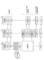
次に、第1の実施形態よりもセキュアなシステム構成とした第2の実施形態にかかる制御装置について図8を用いて説明する。図8は、第2の実施形態にかかる制御装置の構成を示すブロック図である。なお、構成については前述の第1の実施形態と重複する部分については同一の符号を用い説明は省略する。
(Second Embodiment)
Next, a control apparatus according to the second embodiment having a system configuration more secure than that of the first embodiment will be described with reference to FIG. FIG. 8 is a block diagram illustrating a configuration of a control device according to the second embodiment. In addition, about the structure, the part which overlaps with above-mentioned 1st Embodiment uses the same code | symbol, and abbreviate | omits description.
本実施形態の制御装置100は、図8に示すように、先述した図1に示した第1の実施形態の基本構成にセキュリティ認証部200を追加した構成となっている。このセキュリティ認証部200は、暗号化/復号部201、認証機能部202、および認証データベース(認証DB)203を備えている。本実施形態では、送受信するフレームのセーフティデータ部に、正常に復号できたか否かの判定を行うための特定のデータと、認証用のデータ(IDおよびパスワード)からなるセキュリティヘッダが含められる(図9A)。
As shown in FIG. 8, the
暗号化/復号部201は、フレームの送受信の際のデータ暗号化/複合を行う機能部であり、暗号化/復号の方式は共通鍵や、秘密鍵方式などシステム共通の暗号化方式や通信セッション単位で固有の暗号化方式などを用いて行う。また、暗号化/復号部201は、受信したフレーム内の復号対象のデータ(例えば、セーフティデータ)を所定の鍵を用いて復号し、この復号対象のデータ内の特定データが正常に読み取れれば復号成功として復号したデータを含むフレームを後段に転送し、上記特定データが正常に読み取れない場合は復号失敗として受信フレームを破棄する。 The encryption / decryption unit 201 is a functional unit that performs data encryption / decryption at the time of transmission / reception of a frame. Use a unique encryption method for each unit. Also, the encryption / decryption unit 201 decrypts the decryption target data (for example, safety data) in the received frame using a predetermined key, and if the specific data in the decryption target data can be read normally The frame including the decoded data is transferred to the subsequent stage as the decoding success, and when the specific data cannot be read normally, the received frame is discarded as the decoding failure.
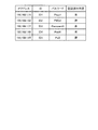
また、暗号化/復号部201は、受信したフレームの暗号化されたセーフティデータが正常に復号できた場合でも認証機能部202により、図9Bに示すような送信元アドレス(図9BではIPアドレス)、IDおよびパスワードを含む認証用データを記憶する認証DB203を参照し、そのデータの送信元が正当なIDとパスワードを送信しているか否かを判定する認証を行う。そして、認証機能部202は、認証が成功した場合は受信したフレームを後段に転送し、認証が失敗した場合は受信したフレームを破棄する。本構成により、正しく暗号化されていないデータや認証が失敗した受信フレームはセーフティ処理部103の前段で破棄されるため、よりセキュアな制御が可能になる。なお、図9Bに示すように認証DB203に認証済み判定項目を設け、認証に成功した場合は、認証済み判定として「済」を設定し、「済」の場合は、同一の送信元から受信するフレームの認証を省略することもできる。
In addition, the encryption / decryption unit 201 uses the
(第3の実施形態)
次に、第3の実施形態にかかる制御装置について、図面を参照して説明する。なお、構成については第1の実施形態で述べた図1を元に説明をする。なお、第1の実施形態と重複する部分についての詳細な説明は省略する。
(Third embodiment)
Next, a control device according to a third embodiment will be described with reference to the drawings. The configuration will be described based on FIG. 1 described in the first embodiment. Note that a detailed description of portions overlapping the first embodiment is omitted.
本実施形態におけるセキュリティ処理部101は、先述した第1の実施形態のものと同様であり、図2に示した監視処理フローに基づいてサービス不能攻撃を検出し、セーフティデータ置換部102に受信禁止信号を伝達する。
The
本実施形態におけるセーフティデータ置換部102は、先述した第1の実施形態のものがサービス不能攻撃を検出している間およびその直後のみ健全性確認データを置換する処理を行っていたのに対し、本実施形態では、セーフティデータ置換部102は一度サービス不能攻撃を受けた後は、サービス不能攻撃の検出有無に関わらず、健全性確認データについては継続して置換処理を施す。以下に、セーフティデータ置換部102の処理について図10を用いて説明する。図10は、セーフティデータ置換部102の動作フローを示すフローチャートである。
While the safety
本実施形態では、受信禁止中信号がONの場合(S501でYes)、つまりサービス不能攻撃を受けているとき、第1の実施形態と同様に、処理実施判定部107が、前回、セーフティデータ置換部102からセーフティ処理部103に送信したフレーム(前回出力フレーム)を採用し(S502)、データ置換部108がそのセーフティヘッダを置換し(S503)、さらに符号計算・付与部109が再計算した誤り検出符号を付与して(S504)、これらの置換処理を施した置換後のフレームをセーフティ処理部103に送信する(S505)。また、受信禁止中信号が一度ONとなった場合、処理実施判定部107は、受信禁止中信号がONとなったことを記憶する。
In this embodiment, when the reception prohibition signal is ON (Yes in S501), that is, when a denial-of-service attack is received, the process
一方、受信禁止中信号がOFFの場合(S501でNo)でセキュリティ処理部101から受信したフレームがあると(S506でYes)、処理実施判定部107は、過去に受信禁止中信号がONになったか否かを判定する(S507)。もし過去に一度もサービス不能攻撃を受けていない場合(S507でNo)、処理実施判定部107は、受信したフレームをそのままセーフティ処理部103へ転送する(S513)。セキュリティ処理部101から受信したフレームが無い場合は(S506でNo)、S501に戻る。
On the other hand, when the reception prohibited signal is OFF (No in S501) and there is a frame received from the security processing unit 101 (Yes in S506), the processing
また、過去に一度でもサービス不能攻撃を受けた場合は(S507でYes)、さらに受信フレームがあるか確認し、あれば(S508でYes)、処理実施判定部107は、図3に示すような受信フレームに含まれている誤り検出符号(CRC)を用いてデータの健全性を確認する(S509)。この確認で誤りが検出されれば(S509でNo)、処理実施判定部107は受信フレームを破棄する(S513)。そうでなければ(S509でYes)、データ置換部108がセーフティヘッダの置換を行い(S510)、符号計算・付与部109が誤り検出符号を再計算し付与し(S511)、置換後のフレームをセーフティ処理部103へ送信する(S512)。なお、S512およびS513の後、ならびにS508で受信フレームなしと判断される場合(No判定)、S508に戻る。
Also, if there has been a denial-of-service attack even once in the past (Yes in S507), it is confirmed whether there is a further received frame (Yes in S508). The soundness of the data is confirmed using an error detection code (CRC) included in the received frame (S509). If an error is detected in this confirmation (No in S509), the process
データ置換部108がS509でセーフティヘッダ(例えば、シーケンス番号)を更新する際のインクリメント値は、サービス不能攻撃から復帰した際のセーフティデータ置換部102からセキュリティ処理部101へ送信したフレームのセーフティヘッダの前回値と新たに受信したフレームのセーフティヘッダの値との差分を用いる。
The increment value when the
例えば、サービス不能攻撃中にシーケンス番号が200までインクリメントされ、次に受信したシーケンス番号が190だった場合、上記差分値は、
200−190=10、
となる。つまり次回出力する新規受信フレームからはシーケンス番号を10+1=11だけインクリメントすることにより、置換後フレーム内のシーケンス番号は
190+11=201>200(前回値)、
となり、置換後のフレームを受けるセーフティ処理部103は正常に動作を継続することが可能となる。逆に、新規に受信したフレーム内のシーケンス番号が230と、前回値の200よりも進んでいた場合、上記差分値は、
200−230=−30、
となる。つまり、次回出力する新規受信フレームからはシーケンス番号を−30+1=−29だけインクリメント(29デクリメント)することにより、置換後フレーム内のシーケンス番号は、
230−29=201>200(前回値)、
となって、この場合もセーフティ処理部103は正常に動作を継続することが可能になる。本処理はシーケンス番号に対してだけでなく、タイムスタンプなど他の健全性確認データに対してもでも同様の処理を行う。
For example, if the sequence number is incremented to 200 during a denial of service attack and the next received sequence number is 190, the difference value is
200-190 = 10,
It becomes. That is, by incrementing the sequence number by 10 + 1 = 11 from the newly received frame to be output next time, the sequence number in the replaced frame is 190 + 111 = 201> 200 (previous value),
Thus, the
200−230 = −30,
It becomes. That is, by incrementing the sequence number by −30 + 1 = −29 (29 decrement) from the newly received frame to be output next time, the sequence number in the replaced frame becomes
230−29 = 201> 200 (previous value),
In this case, the
後段のセーフティ処理部103の動作は、第1の実施形態において先述したとおりである。
The operation of the
なお、本実施形態においてもシステムのアベイラビリティを、より考慮する構成として、許容値としてリトライ回数を設けるようにしてもよい。この場合、セーフティデータ確認部112が上記のようにエラーと判定した場合にそのフレームのデータを採用せず、前回セーフティ処理部103へ送信したフレームのデータを採用するとともに、エラー回数を保持するようにする。そして、そのエラー回数がリトライ回数分連続してエラーが生じた場合にセーフティデータ確認部112が異常とみなし、制御演算部111に安全停止処理へ移行させることにより、先述のように許容値を超えると直ちに安全停止処理へ移行するよりも、システムのアベイラビリティが保たれる。
In this embodiment, the number of retries may be provided as an allowable value as a configuration that further considers system availability. In this case, when the safety
図11に、本実施形態にかかる制御装置100の、セキュリティ処理部101、セーフティデータ置換部102、およびセーフティ処理部103間のデータの流れおよび動作を示す。
FIG. 11 shows the data flow and operation among the
図11に示すように、通常時は、受信したフレーム(data1)をそのままセーフティ処理部103まで転送し、サービス不能攻撃中(受信禁止中信号ON)は、セーフティデータ置換部102は、前回、セーフティ処理部103へ送信したフレーム(data2)を採用し、その健全性確認データを置換したフレーム(data2−1、data2−2)を生成し、セーフティ処理部103へ送信する。また、セーフティデータ置換部102は、サービス不能攻撃が収まった後も、新規受信したフレーム内の健全性確認データを置換し続け、置換後のフレーム(data k−3、data L−4)を後段のセーフティ処理部103へ転送する。
As shown in FIG. 11, in a normal time, the received frame (data 1) is transferred to the
本実施形態によれば、第1の実施形態の効果に加え、サービス不能攻撃の収束を検出した後も継続して健全性確認データの置換処理を行うことにより、第1の実施形態において図6を用いて説明したような、ある出力回数分置換処理を施したフレームをセーフティ処理部103へ送信するといった処理が不要となり、セーフティデータ置換部102の処理を簡素化した制御装置100を提供できる。
According to the present embodiment, in addition to the effects of the first embodiment, the replacement process of soundness confirmation data is continuously performed even after the convergence of the denial of service attack is detected, so that FIG. Thus, the processing for transmitting the frame subjected to the replacement processing for a certain number of output times as described above to the
また、第2の実施形態として前述した図8に示したセキュリティ認証部200を含む、よりセキュアな構成を採用することも可能である。この構成をとった場合、暗号化機能および認証機能により正当なフレームのみがセーフティデータ置換部102へ伝送されることになり、セキュリティ機能がより向上する。
Further, it is possible to adopt a more secure configuration including the
(第4の実施形態)
次に、第4の実施形態にかかる制御装置ついて、図12および図13を用いて説明する。図12および図13は、本実施形態にかかる制御装置100およびユーザ端末の構成を示すブロック図である。なお、構成については前述の諸実施形態と重複する部分については同一の符号を用い説明は省略する。
(Fourth embodiment)
Next, a control device according to a fourth embodiment will be described with reference to FIGS. 12 and 13 are block diagrams showing the configuration of the
本実施形態では、制御装置100の外部に許容時間入力部301とアラーム表示部302を具備したユーザ端末(ユーザ側装置)300を設け、許容時間入力部301とアラーム表示部302をそれぞれセーフティデータ置換部102の処理実施判定部107に接続する。なお、制御装置100とユーザ端末300との接続手段は、図12に示すような専用の接続線に限らず、図13に示すような上位装置等に接続するための制御用通信路(ネットワーク)を用いた構成としてもよい。また、ユーザ端末300は、キーボードやマウス等の入力装置、液晶モニタ等の表示装置、および、処理実施判定部107に接続するためのインタフェースを備えた、PCなどの汎用的な情報処理装置でもよいし、専用に構成されたハードウェアでもよい。PCなどの汎用的な情報処理装置を用いる場合、当該情報処理装置にインストールされた制御プログラムと当該情報処理装置のハードウェアとが協働することにより、上記許容時間入力部301とアラーム表示部302の機能を実現する。
In the present embodiment, a user terminal (user side device) 300 including an allowable
次に、本実施形態にかかる制御装置100と、当該制御装置100に接続するユーザ端末300の動作について図14を用いて説明する。図14は、第4の実施形態におけるセーフティデータ置換部102の動作フローを示すフローチャートである。
Next, operations of the
以下では、ユーザ端末300内の許容時間入力部301から処理実施判定部107へ、サービス不能攻撃に対する許容時間が設定されているものとする。
In the following, it is assumed that an allowable time for a denial of service attack is set from the allowable
処理実施判定部107は、受信禁止中信号がOFFの場合(S601でNo)、セキュリティ処理部101から受信したフレームがあると(S610でYes)、この受信したフレームをセーフティ処理部103へそのまま転送し(S611)、無い場合は(S610でNo)、処理をS601に戻す。一方、受信禁止中信号がONの場合(S601でYes)、サービス不能攻撃が生じている時間(継続時間)を計測する(S602)。
When the reception prohibition signal is OFF (No in S601), the processing
そして、サービス不能攻撃の継続時間が設定された許容時間(許容値)内であれば(S603でYes)、処理実施判定部107は、セーフティデータ置換部102からセーフティ処理部103へ前回送信したフレーム(前回出力フレーム)を採用し、この前回出力フレームをデータ置換部108に転送する(S604)。
If the duration of the denial of service attack is within the set allowable time (allowable value) (Yes in S603), the processing
そして、第1の実施形態で前述したように、データ置換部108による前回出力フレームのセーフティヘッダの置換を行い(S605)、符号計算・付与部109による誤り検出符号の再計算および付与を行って(S606)、セーフティ処理部103へ置換後のフレームを送信する(S607)。
As described above in the first embodiment, the safety header of the previous output frame is replaced by the data replacement unit 108 (S605), and the error detection code is recalculated and added by the code calculation /
一方、サービス不能攻撃が設定された許容時間を超えた場合(S603でNo)、処理実施判定部107は、ユーザ端末300に警告を通知する(S608)。ユーザ端末300への警告の通知は、上記の制御装置100とユーザ端末300との接続手段(専用の接続線または制御用通信路(ネットワーク))を介して行うが、制御用通信路の場合は、サービス不能攻撃中は半二重通信では警告が通知できなくなるため、通信I/F部104は全二重通信により警告を通知する機能を備える。
On the other hand, when the denial-of-service attack exceeds the set allowable time (No in S603), the processing
処理実施判定部107がユーザ端末300への警告を通知した後、セーフティデータ置換部102は、前回、セーフティ処理部103へ送信したフレームの健全性確認データをデータ置換部108および符号計算・付与部109にて更新することなく、そのフレームをそのままセーフティ処理部103へ送信する(S609)。システムのアベイラビリティの観点から、セーフティ処理部103のエラー判定がn回連続検出で安全停止する仕様になっていた場合、セーフティデータ置換部102は、n回連続で前回値をもつ健全性確認データを含むフレームをセーフティ処理部103へ送信する。セーフティ処理部103は図5に示した動作フローに基づき動作し、セーフティデータ確認部112が健全性確認データが更新されていないことを検出すると、制御演算部111が安全停止処理へと遷移する。
After the processing
図15に、本実施形態にかかる制御装置100の、セキュリティ処理部101、セーフティデータ置換部102、およびセーフティ処理部103間のデータ(フレーム)の流れおよび動作を示す。
FIG. 15 shows the flow and operation of data (frames) among the
同図に示すように、通常時、および、受信禁止中信号ONでその後の経過時間が許容時間内の場合、図7を用いて前述したデータの流れとなるが、経過時間が許容時間を過ぎると(許容時間OVER)、その後、経過時間が許容時間を過ぎる直前のフレーム(data2−2)を連続して(繰り返して)セーフティ処理部103へ送信している。その結果、セーフティ処理部103で安全停止処理へ遷移しシステムは安全停止することとなる。
As shown in the figure, in the normal state and when the reception-prohibited signal is ON and the subsequent elapsed time is within the allowable time, the data flow described above with reference to FIG. 7 is performed, but the elapsed time exceeds the allowable time. (Allowable time OVER), and then the frame (data2-2) immediately before the elapsed time exceeds the allowable time is continuously (repeatedly) transmitted to the
本実施形態では、以上のようにして、サービス不能攻撃が発生し、許容時間内まではデータ置換部108が前述の健全性確認データの置換を行い、符号計算・付与部109が誤り検出符号を再計算し付与したフレームを生成し、セーフティ処理部103へ転送するが、許容時間を超えた場合、セーフティデータ置換部102は、データ置換部108および符号計算・付与部109による置換処理を停止し、同一のフレームをセーフティ処理部103に転送することにより、システムを安全停止させる。
In this embodiment, as described above, a denial-of-service attack occurs, the
本実施形態によれば、安全停止処理に遷移する前に上記のようにユーザに対してシステムが安全停止する旨の警告を通知することで、ユーザによる対処の機会を提供することができ、また、ユーザが許容時間を任意に設定可能としたことで、制御対象プラントごとに異なる制御応答許容時間に合わせて、サービス不能攻撃に伴う安全停止処理へ遷移するか否かの判定時間をユーザが調整することが可能となる。 According to the present embodiment, before the transition to the safe stop process, the user can be provided with an opportunity to cope by notifying the user of the warning that the system will be safely stopped as described above. By allowing the user to set the permissible time arbitrarily, the user adjusts the determination time to determine whether or not to transition to the safe stop process associated with a denial of service attack according to the permissible control response time for each controlled plant. It becomes possible to do.
また、本実施形態においても、第2の実施形態として前述した図8に示したセキュリティ認証部200を含む、よりセキュアな構成を採用することが可能である。この構成をとった場合、暗号化機能および認証機能により正当なフレームのみがセーフティデータ置換部102へ伝送されることになり、セキュリティ機能がより向上する。
Also in this embodiment, it is possible to adopt a more secure configuration including the
以上説明したとおり、第1から第4の実施形態によれば、制御装置におけるセキュリティ機能とセーフティ機能の両立を実現し、当該制御装置を含むシステム全体のアベイラビリティの低減を回避することができる。 As described above, according to the first to fourth embodiments, it is possible to realize both the security function and the safety function in the control device, and avoid the reduction of the availability of the entire system including the control device.
本発明のいくつかの実施形態を説明したが、これらの実施形態は、例として提示したものであり、発明の範囲を限定することは意図していない。これら新規な実施形態は、その他の様々な形態で実施されることが可能であり、発明の要旨を逸脱しない範囲で、種々の省略、置き換え、変更を行うことができる。これら実施形態やその変形は、発明の範囲や要旨に含まれるとともに、特許請求の範囲に記載された発明とその均等の範囲に含まれる。 Although several embodiments of the present invention have been described, these embodiments are presented by way of example and are not intended to limit the scope of the invention. These novel embodiments can be implemented in various other forms, and various omissions, replacements, and changes can be made without departing from the scope of the invention. These embodiments and modifications thereof are included in the scope and gist of the invention, and are included in the invention described in the claims and the equivalents thereof.
100 制御装置
101 セキュリティ処理部
102 セーフティデータ置換部
103 セーフティ処理部
104 通信I/F部
105 通信処理部
106 監視部
107 処理実施判定部
108 データ置換部
109 符号計算・付与部
110 セーフティデータ生成部
111 制御演算部
112 セーフティデータ確認部
113 I/Oデータ入出力部
200 セキュリティ認証部
201 暗号化/復号部
202 認証機能部
203 認証DB
300 ユーザ端末
301 許容時間入力部
302 アラーム表示部
DESCRIPTION OF
300
Claims (11)
前記通信フレームの送受信に係る統計情報を管理する通信処理部と、
前記統計情報を基にサービス不能攻撃を監視する監視部と、
を有するセキュリティ処理部と、
前記監視部によりサービス不能攻撃が検出された場合に、受信した通信フレームに含まれる所定のデータに対する置換処理を実施すると判定する処理実施判定部と、
前記処理実施判定部で置換処理を実施すると判定された場合に、前記セキュリティ処理部から受信した通信フレームの前記所定のデータを健全であるとされる値に置換するデータ置換部と、
前記置換がなされた通信フレームの誤り検出符号を再計算し付与する符号計算・付与部と、
を有するセーフティデータ置換部と、
前記セーフティデータ置換部から受信した通信フレームの前記所定のデータから当該通信フレームの健全性を確認するセーフティデータ確認部と、
前記セーフティデータ確認部により前記セーフティデータ置換部から受信した通信フレームの健全性が確認された場合に、当該通信フレームのデータを基に配下の装置を制御するための制御値を算出する制御演算部と、
前記配下の装置へ前記制御値を出力し、配下の装置からのデータを入力するI/Oデータ入出力部と、
を有するセーフティ処理部と
を具備する制御装置。 A communication interface unit for inputting and outputting communication frames; and
A communication processing unit for managing statistical information related to transmission and reception of the communication frame;
A monitoring unit for monitoring a denial of service attack based on the statistical information;
A security processing unit having
A process execution determination unit that determines to perform a replacement process on predetermined data included in a received communication frame when a denial of service attack is detected by the monitoring unit;
A data replacement unit that replaces the predetermined data of the communication frame received from the security processing unit with a value that is sound when it is determined that the processing execution determination unit performs the replacement processing;
A code calculation / attachment unit that recalculates and gives an error detection code of the communication frame subjected to the replacement;
A safety data replacement unit having
A safety data confirmation unit that confirms the soundness of the communication frame from the predetermined data of the communication frame received from the safety data replacement unit;
A control arithmetic unit that calculates a control value for controlling a subordinate device based on data of the communication frame when the safety of the communication frame received from the safety data replacement unit is confirmed by the safety data confirmation unit When,
An I / O data input / output unit that outputs the control value to the subordinate apparatus and inputs data from the subordinate apparatus;
And a safety processing unit.
前記処理実施判定部は、前記受信禁止信号を受信した場合に、置換処理を実施すると判定し、
前記データ置換部は、前回、前記セーフティデータ置換部から前記セーフティ処理部に送信した通信フレーム中の前記セーフティヘッダを、今回値と前回値の差分が許容範囲内となるようインクリメントした値に置換し、前記符号計算・付与部は、置換後の通信フレームを元に再度誤り検出符号を計算し付与した通信フレームを、前記セーフティ処理部へ送信する
請求項4に記載の制御装置。 The monitoring unit monitors the number of received communication frames as the statistical information, and prohibits the communication processing unit from newly receiving a communication frame if the received number exceeds a predetermined value within a predetermined time. And transmit a reception prohibition signal to the processing execution determination unit of the safety data replacement unit,
The process execution determination unit determines to perform a replacement process when the reception prohibition signal is received,
The data replacement unit replaces the safety header in the communication frame transmitted from the safety data replacement unit to the safety processing unit last time with a value incremented so that the difference between the current value and the previous value is within an allowable range. The control device according to claim 4, wherein the code calculation / assignment unit transmits a communication frame obtained by calculating and adding an error detection code again based on the replaced communication frame to the safety processing unit.
Priority Applications (1)
| Application Number | Priority Date | Filing Date | Title |
|---|---|---|---|
| JP2015236784A JP6633373B2 (en) | 2015-12-03 | 2015-12-03 | Control device |
Applications Claiming Priority (1)
| Application Number | Priority Date | Filing Date | Title |
|---|---|---|---|
| JP2015236784A JP6633373B2 (en) | 2015-12-03 | 2015-12-03 | Control device |
Publications (2)
| Publication Number | Publication Date |
|---|---|
| JP2017103677A true JP2017103677A (en) | 2017-06-08 |
| JP6633373B2 JP6633373B2 (en) | 2020-01-22 |
Family
ID=59017074
Family Applications (1)
| Application Number | Title | Priority Date | Filing Date |
|---|---|---|---|
| JP2015236784A Active JP6633373B2 (en) | 2015-12-03 | 2015-12-03 | Control device |
Country Status (1)
| Country | Link |
|---|---|
| JP (1) | JP6633373B2 (en) |
Cited By (8)
| Publication number | Priority date | Publication date | Assignee | Title |
|---|---|---|---|---|
| JP2019012953A (en) * | 2017-06-30 | 2019-01-24 | 株式会社東芝 | Control device |
| WO2019102811A1 (en) * | 2017-11-24 | 2019-05-31 | オムロン株式会社 | Control device and control system |
| WO2019198456A1 (en) * | 2018-04-13 | 2019-10-17 | オムロン株式会社 | Safety control system and control method in safety control system |
| WO2020090034A1 (en) * | 2018-10-31 | 2020-05-07 | 株式会社日立製作所 | Processing device |
| WO2020110876A1 (en) * | 2018-11-28 | 2020-06-04 | オムロン株式会社 | Controller system |
| JP2020087423A (en) * | 2019-06-20 | 2020-06-04 | オムロン株式会社 | Controller system |
| JP2020095672A (en) * | 2018-11-28 | 2020-06-18 | オムロン株式会社 | Controller system |
| CN115328093A (en) * | 2022-08-26 | 2022-11-11 | 中国矿业大学 | Safety state estimation method of double-time-scale industrial information physical system |
Citations (4)
| Publication number | Priority date | Publication date | Assignee | Title |
|---|---|---|---|---|
| JP2003087317A (en) * | 2001-09-12 | 2003-03-20 | Nec Corp | Apparatus and method for absorbing voice packet delay fluctuation |
| JP2008199138A (en) * | 2007-02-09 | 2008-08-28 | Hitachi Industrial Equipment Systems Co Ltd | Information processor, and information processing system |
| US20100038440A1 (en) * | 2008-08-12 | 2010-02-18 | Kodalfa Bilgi ve Iletisim Teknolojileri San. Tic. A.S. | Method and system for remote wireless monitoring and control of climate in greenhouses |
| JP2015088948A (en) * | 2013-10-31 | 2015-05-07 | 日産自動車株式会社 | Communication relay device and communication relay processing |
-
2015
- 2015-12-03 JP JP2015236784A patent/JP6633373B2/en active Active
Patent Citations (4)
| Publication number | Priority date | Publication date | Assignee | Title |
|---|---|---|---|---|
| JP2003087317A (en) * | 2001-09-12 | 2003-03-20 | Nec Corp | Apparatus and method for absorbing voice packet delay fluctuation |
| JP2008199138A (en) * | 2007-02-09 | 2008-08-28 | Hitachi Industrial Equipment Systems Co Ltd | Information processor, and information processing system |
| US20100038440A1 (en) * | 2008-08-12 | 2010-02-18 | Kodalfa Bilgi ve Iletisim Teknolojileri San. Tic. A.S. | Method and system for remote wireless monitoring and control of climate in greenhouses |
| JP2015088948A (en) * | 2013-10-31 | 2015-05-07 | 日産自動車株式会社 | Communication relay device and communication relay processing |
Cited By (15)
| Publication number | Priority date | Publication date | Assignee | Title |
|---|---|---|---|---|
| JP2019012953A (en) * | 2017-06-30 | 2019-01-24 | 株式会社東芝 | Control device |
| JP7051316B2 (en) | 2017-06-30 | 2022-04-11 | 株式会社東芝 | Control device |
| WO2019102811A1 (en) * | 2017-11-24 | 2019-05-31 | オムロン株式会社 | Control device and control system |
| JP2019096149A (en) * | 2017-11-24 | 2019-06-20 | オムロン株式会社 | Control device and control system |
| US11516229B2 (en) | 2017-11-24 | 2022-11-29 | Omron Corporation | Control device and control system |
| WO2019198456A1 (en) * | 2018-04-13 | 2019-10-17 | オムロン株式会社 | Safety control system and control method in safety control system |
| JP2019185516A (en) * | 2018-04-13 | 2019-10-24 | オムロン株式会社 | Safety control system and control method in safety control system |
| JPWO2020090034A1 (en) * | 2018-10-31 | 2021-09-02 | 株式会社日立製作所 | Processing equipment |
| WO2020090034A1 (en) * | 2018-10-31 | 2020-05-07 | 株式会社日立製作所 | Processing device |
| WO2020110876A1 (en) * | 2018-11-28 | 2020-06-04 | オムロン株式会社 | Controller system |
| CN112673324A (en) * | 2018-11-28 | 2021-04-16 | 欧姆龙株式会社 | Controller system |
| JP2020095672A (en) * | 2018-11-28 | 2020-06-18 | オムロン株式会社 | Controller system |
| JP2020087423A (en) * | 2019-06-20 | 2020-06-04 | オムロン株式会社 | Controller system |
| CN115328093A (en) * | 2022-08-26 | 2022-11-11 | 中国矿业大学 | Safety state estimation method of double-time-scale industrial information physical system |
| CN115328093B (en) * | 2022-08-26 | 2023-09-29 | 中国矿业大学 | Safety state estimation method of double-time scale industrial information physical system |
Also Published As
| Publication number | Publication date |
|---|---|
| JP6633373B2 (en) | 2020-01-22 |
Similar Documents
| Publication | Publication Date | Title |
|---|---|---|
| JP6633373B2 (en) | Control device | |
| US20160344754A1 (en) | Configurable Robustness Agent in a Plant Security System | |
| US20190289020A1 (en) | Provision of secure communication in a communications network capable of operating in real time | |
| US9521120B2 (en) | Method for securely transmitting control data from a secure network | |
| CN109286606B (en) | Firewall for encrypted traffic in a process control system | |
| CN112866427A (en) | Apparatus and method for security of industrial control network | |
| JP5911439B2 (en) | Supervisory control system | |
| EP2767057B1 (en) | Process installation network intrusion detection and prevention | |
| JP2007156669A (en) | Remote maintenance system | |
| CN108011867B (en) | Safe encryption method and system for railway signals | |
| EP4184854A1 (en) | Association control method and related apparatus | |
| EP3769450B1 (en) | Apparatus and method for avoiding deterministic blanking of secure traffic | |
| WO2016170664A1 (en) | Abnormal-packet filtering apparatus and abnormal-packet filtering method | |
| CN104468497A (en) | Data isolation method and device of monitoring system | |
| EP3136681B1 (en) | Wireless relay device, wireless communication system, and wireless communication method | |
| CN115694931A (en) | Relay protection remote operation and maintenance intrusion prevention and detection method and system | |
| CN114600424B (en) | Security system, method, and computer-readable storage medium for filtering data traffic | |
| JP2004151807A (en) | Supervision and control system | |
| JP5402304B2 (en) | Diagnostic program, diagnostic device, and diagnostic method | |
| JP2015041958A (en) | Firewall device | |
| CN105721334B (en) | Method and equipment for determining transmission path and updating ACL | |
| US9811660B2 (en) | Securing a shared serial bus | |
| JP2017192105A (en) | Redundancy processing unit, and abnormality determination method | |
| US20200021610A1 (en) | Data analysis device, method, and storage medium | |
| CN113169865A (en) | Control device, industrial control system, and encryption key life prolonging method |
Legal Events
| Date | Code | Title | Description |
|---|---|---|---|
| A711 | Notification of change in applicant |
Free format text: JAPANESE INTERMEDIATE CODE: A712 Effective date: 20170911 |
|
| A711 | Notification of change in applicant |
Free format text: JAPANESE INTERMEDIATE CODE: A711 Effective date: 20170912 |
|
| A621 | Written request for application examination |
Free format text: JAPANESE INTERMEDIATE CODE: A621 Effective date: 20180807 |
|
| A977 | Report on retrieval |
Free format text: JAPANESE INTERMEDIATE CODE: A971007 Effective date: 20190528 |
|
| A131 | Notification of reasons for refusal |
Free format text: JAPANESE INTERMEDIATE CODE: A131 Effective date: 20190611 |
|
| A521 | Request for written amendment filed |
Free format text: JAPANESE INTERMEDIATE CODE: A523 Effective date: 20190722 |
|
| A131 | Notification of reasons for refusal |
Free format text: JAPANESE INTERMEDIATE CODE: A131 Effective date: 20190827 |
|
| A521 | Request for written amendment filed |
Free format text: JAPANESE INTERMEDIATE CODE: A523 Effective date: 20191028 |
|
| TRDD | Decision of grant or rejection written | ||
| A01 | Written decision to grant a patent or to grant a registration (utility model) |
Free format text: JAPANESE INTERMEDIATE CODE: A01 Effective date: 20191112 |
|
| A61 | First payment of annual fees (during grant procedure) |
Free format text: JAPANESE INTERMEDIATE CODE: A61 Effective date: 20191212 |
|
| R150 | Certificate of patent or registration of utility model |
Ref document number: 6633373 Country of ref document: JP Free format text: JAPANESE INTERMEDIATE CODE: R150 |