JP2017102705A - Autonomous mobile device and autonomous mobile device system - Google Patents
Autonomous mobile device and autonomous mobile device system Download PDFInfo
- Publication number
- JP2017102705A JP2017102705A JP2015235460A JP2015235460A JP2017102705A JP 2017102705 A JP2017102705 A JP 2017102705A JP 2015235460 A JP2015235460 A JP 2015235460A JP 2015235460 A JP2015235460 A JP 2015235460A JP 2017102705 A JP2017102705 A JP 2017102705A
- Authority
- JP
- Japan
- Prior art keywords
- mobile device
- autonomous mobile
- height
- self
- map information
- Prior art date
- Legal status (The legal status is an assumption and is not a legal conclusion. Google has not performed a legal analysis and makes no representation as to the accuracy of the status listed.)
- Pending
Links
- 238000005259 measurement Methods 0.000 claims abstract description 12
- 230000003028 elevating effect Effects 0.000 claims description 5
- 238000012545 processing Methods 0.000 abstract description 7
- 238000012986 modification Methods 0.000 description 21
- 230000004048 modification Effects 0.000 description 21
- 238000010586 diagram Methods 0.000 description 18
- 238000001514 detection method Methods 0.000 description 8
- 238000000034 method Methods 0.000 description 8
- 230000006870 function Effects 0.000 description 2
- 238000003780 insertion Methods 0.000 description 2
- 230000037431 insertion Effects 0.000 description 2
- 230000000694 effects Effects 0.000 description 1
- 230000007613 environmental effect Effects 0.000 description 1
- 238000009434 installation Methods 0.000 description 1
Images


Abstract
Description
本発明は、自律移動装置及び自律移動装置システムに関するものである。 The present invention relates to an autonomous mobile device and an autonomous mobile device system.
従来、自律移動装置として、距離センサで周囲の物体までの方位と距離とを検出し、その検出結果と、予め記憶されている移動領域の地図情報における物体の位置情報とに基づいて、自己位置を推定するものが知られている。
例えば、特許文献1には、次のような自律走行装置が記載されている。
レーザー距離センサで壁までの方位と距離とを検出し、周囲の壁におけるレーザー距離センサと対向する面の輪郭を示すグリッド画像を生成する。そして、このグリッド画像と予め記憶している移動領域内の壁の輪郭を示した地図情報のグリッド画像とを照合し、地図情報のグリッド画像の中で、検出した壁の輪郭のグリッド画像と重なる部分を探し出す。そして、検出した周囲の壁までの方位と距離とに基づいて地図情報上における現在位置を算出し、移動領域内における自己位置を推定する。特許文献1に記載の自律走行装置が備える距離センサは、レーザー光の照射方向を水平方向に走査して、物体のまでの距離を二次元平面で測定し、周囲の物体の距離センサと対向する部分の輪郭を検出できるものであり、自律移動装置に固定されている。
Conventionally, as an autonomous mobile device, a distance sensor detects the azimuth and distance to a surrounding object, and based on the detection result and the position information of the object in the map information of the movement area stored in advance, the self-position It is known to estimate
For example,
The laser distance sensor detects the azimuth and distance to the wall, and generates a grid image indicating the contour of the surface of the surrounding wall facing the laser distance sensor. Then, the grid image is compared with the grid image of the map information indicating the contour of the wall in the moving area stored in advance, and overlaps with the grid image of the detected wall contour in the map information grid image. Find the part. Then, the current position on the map information is calculated based on the detected azimuth and distance to the surrounding wall, and the self position in the moving area is estimated. The distance sensor included in the autonomous traveling device described in
しかしながら、自律移動装置の移動領域内の物体は、その高さ方向の位置によって輪郭が異なることが一般的である。そして、物体によっては、ある高さにおける輪郭では、距離センサによって検出される輪郭と地図情報に記憶されている輪郭との照合は容易であるが、他の高さにおける輪郭では、上記照合が困難な場合がある。
そして、自律移動装置における距離センサを配置した高さが、周囲の物体における上記照合が困難な輪郭となる高さであると、自己位置の推定精度が低下し、自己位置を見失うおそれがある。
However, the outline of an object in the movement area of the autonomous mobile device is generally different depending on the position in the height direction. Depending on the object, it is easy to collate the contour detected by the distance sensor with the contour stored in the map information at the contour at a certain height, but it is difficult to collate the contour at another height. There is a case.
And if the height at which the distance sensor is arranged in the autonomous mobile device is such a height that makes it difficult to collate the surrounding objects, the self-position estimation accuracy is lowered and the self-position may be lost.
上述した課題を解決するために、本発明は、移動手段と、移動領域の地図情報を格納する地図記憶手段と、前記移動領域内に存在する物体との距離を測定する測距手段と、前記測距手段の測定結果から求まる周囲の物体の輪郭情報を前記地図情報に含まれる前記移動領域内の物体の輪郭情報と照合することによって、前記移動領域内における自己位置を推定する推定手段とを備える自律移動装置において、前記測距手段の高さが変更可能であり、前記地図記憶手段は、前記地図情報として前記測距手段の高さに対応した前記移動領域内の物体の輪郭情報を備えていることを特徴とするものである。 In order to solve the above-described problem, the present invention includes a moving unit, a map storage unit that stores map information of a moving region, a distance measuring unit that measures a distance between an object existing in the moving region, Estimating means for estimating self-position in the moving area by collating contour information of surrounding objects obtained from the measurement result of the distance measuring means with the contour information of objects in the moving area included in the map information; In the autonomous mobile device provided, the height of the distance measuring means can be changed, and the map storage means includes contour information of an object in the moving area corresponding to the height of the distance measuring means as the map information. It is characterized by that.
本発明によれば、自律移動装置の自己位置の推定精度を向上することが可能になる。 According to the present invention, it is possible to improve the estimation accuracy of the self position of the autonomous mobile device.
以下、図面を参照して本発明の実施形態の一例について説明する。
図2は、実施形態の自律走行装置である自走ロボット1の説明図であり、図2(a)は、自走ロボット1の上面図、図2(b)は自走ロボット1の右側面図である。自律走行装置としては、車両の上に物を積載し、指定された場所まで無人で物を配送するタイプや、台車などを牽引するタイプなどがある。本実施形態の自走ロボット1は、何れのタイプの自律走行装置においても適用することが可能である。図2中の右側が自走ロボット1の前方である。
Hereinafter, an example of an embodiment of the present invention will be described with reference to the drawings.
2A and 2B are explanatory diagrams of the self-propelled
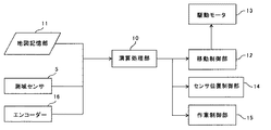
図3は、自走ロボット1の制御システムの一例を示すブロック図である。
図2及び図3に示すように、自走ロボット1は、車両本体2、駆動輪3、補助輪4、駆動モータ13、測域センサ5、駆動輪3の回転数を検出するためのエンコーダ16及び自律走行制御を行う演算処理部10を備える。また、自走ロボット1は、駆動モータ13を制御する移動制御部12、移動領域の地図情報を記憶する地図記憶部11を備える。移動制御部12は、駆動輪3を駆動するための制御信号を作成し、駆動モータ13にその制御信号を送信する。
FIG. 3 is a block diagram illustrating an example of a control system for the self-running
As shown in FIGS. 2 and 3, the self-
図3中のセンサ位置制御部14は、後述するセンサ高調整モータの駆動を制御して、自走ロボット1における測域センサ5の高さを調整する。また、作業制御部15は、停止時の荷物の積み下ろし作業等、自律走行以外の自走ロボット1が行う自動作業の動作を制御する。
The sensor
図2に示すように、自走ロボット1は、車両本体2の前面に移動する方向に現れた障害物などを認識するための非接触式の測域センサ5が配置されている。測域センサ5は、移動領域内に存在する物体との距離を計測して環境データを生成する。演算処理部10は、測域センサ5の計測結果より得た周囲の物体の輪郭データを地図記憶部11に記憶される地図情報に含まれる輪郭データと照合することによって、自走ロボット1の自己位置を推定する推定手段としての機能を有する。
As shown in FIG. 2, the self-
本実施形態では、測域センサ5としてレーザー光Lを照射する一般的な二次元のレーザー測域センサ(レーザーレンジファインダ)を用いており、レーザー光Lの照射方向が略水平となるように配置されている。
測域センサ5は、照射方向を連続的に変化させてレーザー光Lを照射し、その扇型状の検出領域内の物体からの反射光を受光することで、その物体までの距離を測定することができる。また、測域センサ5、走査範囲の中央となる正面方向が、自走ロボット1の直進時の進行方向と一致するように自走ロボット1に配置されている。
測域センサ5としては、他にもミリ波や超音波を使ったアレイや超音波センサの回転操作によって移動領域のデータを得るものを用いても良い。
自律走行制御では、予め地図記憶部11に記憶している地図情報と、オドメトリ(エンコーダ16の回転数から移動距離を算出)による推定される移動距離と、測域センサ5にて検出された距離情報と、をマッチングさせることによって、自己位置の推定を行う。
In the present embodiment, a general two-dimensional laser range sensor (laser range finder) that irradiates the laser beam L is used as the
The
As the
In autonomous traveling control, the map information stored in the map storage unit 11 in advance, the travel distance estimated by odometry (the travel distance is calculated from the rotation speed of the encoder 16), and the distance detected by the
地図記憶部11に記憶している地図情報は、自走ロボット1の運用開始前に、自走ロボット1を移動領域内で移動させ、測域センサ5によって測定した距離情報に基づいて作成し、地図記憶部11に記憶しても良い。詳しくは、自走ロボット1を移動させながら測域センサ5により周囲の物体までの方位と距離とを検出し、検出された物体について測域センサ5が配置された高さにおける測域センサ5と対向する表面の輪郭を示すグリッド画像を生成する。そして、移動の前後でグリッド画像の特徴点を照合して同じ特徴点が最もよく一致するように画像を重ね合わせて行き、移動領域全体の地図情報を作成し、地図記憶部11に記憶する。地図情報作成時に自走ロボット1を移動領域内で移動させる方法としては人間が押すなど手動によっても良いし、自走ロボット1を自動で移動させても良い。
The map information stored in the map storage unit 11 is created based on the distance information measured by the
自走ロボット1が自律走行するときには、測域センサ5で物体までの方位と距離とを検出し、検出された周囲の物体について測域センサ5が配置された高さにおける測域センサ5と対向する表面の輪郭を示すグリッド画像を生成する。そして、このグリッド画像と、地図記憶部11に予め記憶されている移動領域全体の固定障害物の輪郭を示した地図情報のグリッド画像とを照合し、移動領域全体の地図情報のグリッド画像の中で、検出した物体の輪郭のグリッド画像と重なる部分を探し出す。そして、検出した周囲の物体までの方位と距離とに基づいて地図情報上における現在位置を算出し、移動領域内における自己位置を推定する。
When the self-
図4は、移動領域における自走ロボット1の自己位置の推定方法を説明する模式図である。図4(a)は、自走ロボット1と移動領域のレイアウトを構成する固定障害物30との位置関係を示し、図4(b)は、測域センサ5によって検出した固定障害物30の位置を示し、図4(c)は、マッチングによって自己位置を特定することを示す。
FIG. 4 is a schematic diagram for explaining a method for estimating the self position of the self-running
図4(a)に示す移動領域における固定障害物30の位置と形状は、地図情報として地図記憶部11に予め記憶されている。図4(b)で示すように測域センサ5によって固定障害物30の輪郭を検出し、検出結果と地図情報とを照合することによって図4(c)に示すように自己位置を推定する。
The position and shape of the fixed
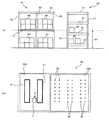
図5は、自走ロボット1の移動領域のレイアウトを構成する二種類の棚と、移動領域内に自走ロボット1を配置した自走ロボットシステム100との一例の説明図である。図5(a)は二段棚40と三段棚50と正面図であり、図5(b)は、自走ロボットシステム100における図5(a)中の高さ「H1」での二次元平面の地図情報の説明図である。図5(b)に示すように、自走ロボットシステム100の移動領域は、二段棚40のみが配置された第一区域400と、三段棚50のみが配置された第二区域500とに区域を分けることができる。
FIG. 5 is an explanatory diagram of an example of two types of shelves constituting the layout of the movement area of the self-running
図5に示す本実施形態の自走ロボットシステム100における自走ロボット1の移動領域は、商品90を保管するための倉庫であり、商品90を整理するための棚(40,50)が並んでいる。図5に示すように、二段棚40は二段用柱部42と二段用棚板41とからなり、三段棚50は三段用柱部52と三段用棚板51とからなる。
自走ロボット1が運用される倉庫等の移動領域においては、何れの高さにおいても輪郭が一定となる障害物のみから構成される環境は少ない。
The movement area of the self-propelled
In a moving area such as a warehouse where the self-propelled
二段棚40及び三段棚50は、棚板(41,51)が配置された高さと、柱部(42,52)のみの高さとでは、輪郭が大きく異なる。測域センサで物体を検出する際に、棚板(41,51)のように、検出する二次元平面における物体の占有面積が広い場合、物体の輪郭を検出する特徴点が多くなり、検出した形状情報と地図情報とのマッチングを行い易い。一方、柱部(42,52)のみのように、検出する二次元平面における物体の占有面積が狭い場合、物体の輪郭を検出する特徴点が少なくなり、検出した輪郭と地図情報における物体の輪郭とのマッチングを行い難くなる。
The contours of the
測域センサ5の高さが「H1」である場合、二段棚40では二段用棚板41の位置する高さであるため第一区域400では二段用棚板41の輪郭を検出でき、特徴点が多いため地図情報とのマッチングを良好に行うことができる。
一方、三段棚50では三段用棚板51の位置する高さではなく、三段用柱部52のみが位置する高さである。このため、第二区域500では、三段棚50の三段用柱部52の輪郭しか検出できず、特徴点が少なく、地図情報とのマッチングの情報として不十分であり、自己位置推定精度が不足して自己位置を消失し動作できなくなる可能性がある。
When the height of the
On the other hand, in the three-
本実施形態の自走ロボット1は、測域センサ5を保持するセンサブラケット6と、センサブラケット6の設置高さを変更可能なセンサベース7とを有するセンサ昇降機構8を備え、図2中の矢印「α」に示すように、測域センサ5の高さが変更可能となっている。
さらに、地図記憶部11には、複数の区域のそれぞれに関連付けて、測域センサ5の検出結果と地図情報とのマッチングを行い易い高さ、すなわち、特徴点が多い二次元平面となる高さの地図情報が記憶されている。
そして、自走ロボット1がそれぞれの区域を走行する際に、特徴点が多い二次元平面の地図情報に対応する高さに測域センサ5の高さを設定して、その測定結果を用いて自己位置の推定を行う。
The self-propelled
Further, the map storage unit 11 associates with each of a plurality of areas, and has a height at which the detection result of the
When the self-propelled
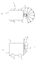
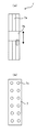
図1は、本実施形態の自走ロボット1の地図記憶部11が記憶する地図情報と、各区域における測域センサ5の高さ方向の位置を示す説明図である。図1(a)は地図記憶部11に記憶される地図情報の一例の説明図である。第一区域400については二段用棚板41が配置された高さ「H1」における二次元平面の地図情報を記憶しており、第二区域500については三段用棚板51が配置された高さ「H2」における二次元平面の地図情報を記憶している。
図1(b)は、自走ロボット1が第一区域400を走行する際の測域センサ5の高さ方向の位置を示しており、図1(c)は、自走ロボット1が第二区域500を走行する際の測域センサ5の高さ方向の位置を示している。
FIG. 1 is an explanatory diagram showing map information stored in the map storage unit 11 of the self-running
FIG. 1B shows the position in the height direction of the
自走ロボット1は、第一区域400を走行するときには、測域センサ5の高さを「H1」に設定し、図1(a)中の左図で示す第一区域400の高さ「H1」における二次元平面の地図情報と、測域センサ5の検出結果とに基づいて自己位置を推定する。また、第二区域500を走行するときには、測域センサ5の高さを「H2」に設定し、図1(a)中の右図で示す第二区域500の高さ「H2」における二次元平面の地図情報と、測域センサ5の検出結果とに基づいて自己位置を推定する。
このように、走行しようとする区域に合わせて特徴点の多い高さの地図情報を用意して、測域センサ5をその地図情報に対応した高さに合わせて自律走行を行う。
When the self-propelled
As described above, map information having a height with many feature points is prepared according to the area to be traveled, and the
自走ロボット1では、走行すべき移動領域の中で、特徴点が見つけ易い高さが同じ固定障害物ごとに、地図情報上での区域を区切る。そして、各区域内では、特徴点が多い所定の高さの地図情報を用い、測域センサ5の高さもこの所定の高さに調整する。そして、測域センサ5の検出結果と地図情報との照合を行いながら自己位置を推定して自律走行する。
これにより、自走ロボット1は、二次元平面の形状が、高さによって異なる固定障害物が配置された移動領域内を走行する場合において、自己位置の推定精度の向上を図ることができる。
In the self-propelled
Thereby, the self-running
ある高さに配置された距離センサを用いて、高さが異なる障害物までの距離を検出する方法として、距離センサのレーザー光の照射方向の傾きを変更する方法が考えられる。しかし、この方法では斜めに照射されるレーザー光の手前側に死角が生じてしまう。
これに対して、自走ロボット1では、距離センサである測域センサ5の高さを変更することで、各区域の特徴点が見つけ易い所定の高さに測域センサ5の高さを合わせることができ、特徴点が見つけ易い所定の高さにおいて、死角ができることを防止できる。
As a method for detecting a distance to an obstacle with a different height using a distance sensor arranged at a certain height, a method of changing the inclination of the irradiation direction of the laser light of the distance sensor is conceivable. However, in this method, a blind spot is generated on the near side of the laser beam irradiated obliquely.
On the other hand, in the self-running
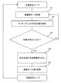
図6は、自走ロボット1の自律走行の開始から、自律走行の終了まで繰り返される位置推定ループ制御のフローチャートである。
自律走行中は、測域センサ5によって障害物データを取得し(S1)、地図情報とのマッチングにより自己位置を推定する(S2)。推定した自己位置に基づいて、第一区域400と第二区域500との何れか一方から他方へと、自己位置の属する区域が変わったか否かを判断する(S3)。区域が変わった場合(「S3」で「Yes」)は、該当区域の所定の高さの地図情報を呼び出し(S4)、測域センサ5の高さを所定の高さに変更し(S5)、位置推定ループを繰り返す。また、区域が変わっていない場合(「S3」で「No」)は、測域センサ5の高さを変えることなく、位置推定ループを繰り返す。
FIG. 6 is a flowchart of position estimation loop control that is repeated from the start of autonomous running of the self-running
During autonomous traveling, obstacle data is acquired by the range sensor 5 (S1), and the self-position is estimated by matching with map information (S2). Based on the estimated self position, it is determined whether or not the area to which the self position belongs has changed from one of the
図6に示すように、自己位置の推定によって、特徴点が多い所定の高さが異なる区域に進入する場合に、該当区域の所定の高さにおける地図情報を呼び出すとともに測域センサ5の高さを自動的に調整して、自己位置の推定を行うようにする。
As shown in FIG. 6, when a predetermined height with many feature points enters a different area by estimating the self-location, the map information at the predetermined height of the corresponding area is called and the height of the
次に、各区域の特徴点が多い高さの二次元平面の地図情報を作成する方法について説明する。上述したように、自走ロボット1の運用開始前に、自走ロボット1を移動領域内で移動させる際に、測域センサ5の高さを各区域における特徴点が多い高さに設定して移動させる。これにより、各区域の特徴点が多い高さにおける各区域内に存在する固定障害物との距離を測定することができ、各区域の特徴点が多い高さの二次元平面の地図情報を作成することができる。また、測域センサ5で実際に測定した特徴点に基づいて地図情報を作成するため、自律走行時の測域センサ5と測定結果と地図情報との照合が行い易くなる。
自走ロボット1を移動領域内で移動させて実際に測定する方法に限らず、移動領域内の固定障害物の配置に関する電子データがある場合は、この電子データに基づいて、各区域の特徴点が多い高さの二次元平面の地図情報を作成してもよい。
Next, a method for creating map information on a two-dimensional plane having a large number of feature points in each area will be described. As described above, when the self-propelled
Not only the method of actually measuring by moving the self-propelled
上述した実施形態では、棚板(41,51)の高さが異なる二種類の棚(40,50)が二つの区域(400,500)にそれぞれ配置された構成について説明した。複数の区域同士の間で、特徴的な輪郭となる高さが互いに異なる複数種の障害物としては棚に限るものではない。例えば、机は天板が位置する高さと、天板を支える足のみが位置する高さとでは、輪郭が異なる。このため、区域によって天板の高さが異なる机や座面の高さが異なる椅子が配置された移動領域においても本実施形態の自走ロボット1を配置することができる。
In the above-described embodiment, the configuration in which two types of shelves (40, 50) having different heights of the shelf boards (41, 51) are arranged in the two sections (400, 500), respectively, has been described. A plurality of types of obstacles having different heights as characteristic contours between a plurality of areas are not limited to shelves. For example, the contour of the desk differs between the height at which the top plate is positioned and the height at which only the feet that support the top plate are positioned. For this reason, the self-propelled
第一区域400については高さ「H1」の地図情報、第二区域500については高さ「H2」の地図情報を記憶する構成について説明した。地図記憶部11に記憶する地図情報として、複数の区域についてそれぞれ複数の高さでの地図情報を記憶させる構成としてもよい。
The configuration has been described in which the map information having the height “H1” is stored for the
また、移動領域を複数の区域に分割して地図情報を持つものに限らず、移動領域の全体の地図情報として複数の高さでの地図情報を記憶させる構成としてもよい。
例えば、オフィス環境では、机と椅子とが配置されている。椅子は座面が位置する高さと、座面を支える足のみが位置する高さとでは、輪郭が異なる。また、一般的に、机の天板は椅子の座面よりも高い位置にある。そこで、地図情報としては、机の天板の高さにおける二次元平面の地図情報と、椅子の座面の高さにおける二次元平面の地図情報とを記憶しておく。そして、自律走行開始時には、測域センサ5の高さを机の天板の高さとして自律走行を行い、地図情報とオドメトリとに基づいて、周囲に椅子がある位置に到達したと判断した場合は、測域センサ5の高さを座面の高さに変更し、自律走行を行う構成としても良い。
Moreover, it is good also as a structure which memorize | stores the map information in several height as map information of not only the thing which divides | segments a movement area | region into a some area but has map information but the whole movement area | region.
For example, in an office environment, a desk and a chair are arranged. The chair has a different contour between the height at which the seating surface is located and the height at which only the feet supporting the seating surface are located. In general, the top of the desk is higher than the seat surface of the chair. Therefore, as the map information, two-dimensional plane map information at the height of the table top and two-dimensional plane map information at the height of the seat surface of the chair are stored. And at the time of autonomous running start, when autonomous driving is performed with the height of the
このように、区域を分割しないで、地図情報とオドメトリとに基づいて、周囲の障害物における特徴点の多い高さが変わったと判断した場合に測域センサ5の高さを変更する構成を適用できる移動領域はオフィス環境に限るものではない。例えば、棚板の高さが異なる棚が区域に分けて配置されておらず、混在する倉庫環境においても適用可能である。
In this way, a configuration is adopted in which the height of the
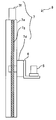
図7は、センサ昇降機構8のセンサベース7の説明図である。図7(a)は、センサブラケット6を自動で昇降するセンサベース7の説明図であり、図7(b)は、手動でセンサブラケット6を上下方向の位置を変更するセンサベース7の説明図である。
FIG. 7 is an explanatory diagram of the
図7(a)のセンサベース7はガイド7aと移動テーブル7bとからなるスライドテーブルである。センサベース7はセンサ高調整モータを備えており、センサ高調整モータが駆動することでガイド7aに対する移動テーブル7bの上下方向の位置が変更される。そして、この移動テーブル7bにセンサブラケット6が固定されており、センサ位置制御部14がセンサ高調整モータの駆動を制御することで、センサブラケット6の高さが変化する。これにより、自走ロボット1が走行する区域が変わるときに、センサブラケット6に保持された測域センサ5の高さを自動調整することが可能となる。測域センサ5の高さを自動的に調整することで、複数の区域間を往来する場合に、測域センサ5の高さ調整のための時間が取られることを防止できる。
The
図7(b)のセンサベース7は、位置決め用のボス穴7cを備える構成である。センサブラケット6に位置決めピンを設け、位置決めピンを挿入するボス穴7cの高さを変更することで、センサブラケット6に保持された測域センサ5の高さを調整することが可能となる。
手動で高さを調整する構成は、自走ロボット1が走行する区域が変わる際に、自走ロボット1が停止して、次に走行する予定の区域の所定の高さに測域センサ5の高さを手動で調整し、自律走行を再開させる。
The
The configuration in which the height is manually adjusted is that when the area where the self-propelled
自走ロボットシステム100としては、特徴点が多い高さの異なる第一区域400と第二区域500との間で一台の自走ロボット1を往来させる構成に限るものではない。第一区域400と第二区域500とのそれぞれに自走ロボット1を配置してもよい。
この場合、第一区域400に配置する自走ロボット1は、測域センサ5の高さを「H1」とし、地図記憶部11に記憶する地図情報としては第一区域400の高さ「H1」における二次元平面の地図情報のみとしてもよい。同様に、第二区域500に配置する自走ロボット1は、測域センサ5の高さを「H2」とし、地図記憶部11に記憶する地図情報は第二区域500の高さ「H2」における二次元平面の地図情報のみとする。
The self-propelled
In this case, the self-propelled
このように、区域ごとに自走ロボット1を配置する構成では、測域センサ5の高さが変更可能であることにより、特徴点の多い高さが異なる各区域に配置する自走ロボット1の共通化を図ることができ、調達コストの削減を図ることができる。
また、区域ごとに自走ロボット1を配置する場合は、測域センサ5の高さを変更する頻度が低い。このため、図7(b)に示すセンサベース7を備えるセンサ昇降機構8のように、手動で測域センサ5の高さを変更する構成とすることで、測域センサ5の高さを自動で変更できる構成に比べて自走ロボット1の一台当たりのコストの削減を図ることができる。
Thus, in the structure which arrange | positions the self-propelled
Moreover, when arrange | positioning the self-propelled
図8は、センサ昇降機構8の他の例の説明図である。
図8に示すセンサ昇降機構8のセンサベース7は、移動ステージ部7d、リニアステージ7e、ネジ軸7g及びネジ軸回転モータ7fを備える。ネジ軸回転モータ7fの回転駆動を制御することにより、センサブラケット6が固定された移動ステージ部7dが上下方向に移動し、センサブラケット6に保持された測域センサ5の高さを自動調整することが可能となる。
FIG. 8 is an explanatory diagram of another example of the
The
〔変形例1〕
次に、自走ロボット1の一つ目の変形例(以下、「変形例1」という)について説明する。
図9は、変形例1の自走ロボット1の説明図であり、図9(a)は、自走ロボット1の上面図、図9(b)は、自走ロボット1の右側面図である。
[Modification 1]
Next, a first modified example (hereinafter referred to as “modified example 1”) of the self-running
FIG. 9 is an explanatory diagram of the self-running
変形例1の自走ロボット1は、測域センサ5として、一つの中央測域センサ5aと二つの端部測域センサ5bとの三つの測域センサを備える。そして、一つの中央測域センサ5aは自動で昇降可能なセンサベース7に取り付けられている。
複数の測域センサ5を用いることによって計測する特徴点が多くなり、検出した形状情報と地図情報とのマッチングを行い易くなり、自己位置の推定精度が向上する。
The self-propelled
The use of a plurality of
〔変形例2〕
次に、自走ロボット1の二つ目の変形例(以下、「変形例2」という)について説明する。
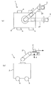
図10は、変形例2の自走ロボット1の説明図であり、図10(a)は、自走ロボット1の上面図、図10(b)は右側面図である。
[Modification 2]
Next, a second modification of the self-running robot 1 (hereinafter referred to as “
FIG. 10 is an explanatory diagram of the self-propelled
変形例2の自走ロボット1は、測域センサ5を多軸のロボットアーム27に設置した構成である。
図10(b)中の矢印「α」で示すように、ロボットアーム27の先端を上下方向に移動させるように制御することで、測域センサ5の専用の昇降手段を設けることなく、測域センサ5の上下方向の位置を変更することが可能となる。
また、測域センサ5をロボットアーム27に設けることで、上下方向だけでなく、左右や前後方向、回転方向にも測域センサ5の位置を調整できるようになる。
自律走行を行う際には、一つの区域内では、測域センサ5の上下方向の位置を一定に保つことで、当該区域における特徴点の多い所定の高さにおける地図情報に基づいて適切な自己位置の推定を行うことができる。
The self-propelled
As indicated by an arrow “α” in FIG. 10B, the range of the
Further, by providing the
When autonomous driving is performed, in one area, the vertical position of the
さらに、ロボットアーム27にハンドやツールを持たせることによって、自走ロボット1の停止時にはアーム作業を行う。また、アーム作業を行う際の周囲の物体とロボットアーム27との距離を測定する位置決めセンサとして、測域センサ5を用いる。このように、測域センサ5によって測定した情報をロボットアーム27の動作制御に用いることで、測域センサ5をアーム作業用のセンサとして利用できるため、自律走行用とアーム作業用とのそれぞれのセンサを別途に設ける必要がなくなる。これにより、センサの個数を削減でき、低コスト化を図ることが可能となる。
Further, by providing the
また、測域センサ5として、周囲の360[°]を検出できない距離センサを用いても、ロボットアーム27の向きを変えることで、周囲の360[°]の環境データを得ることが可能となり、自己位置の推定精度が向上する。
また、ロボットアーム27の先端を自走ロボット1の後ろ側に向けることで、後進時に前進時と同様に障害物を検出でき、前進時と同じように動作することが可能となる。
Further, even if a distance sensor that cannot detect the surrounding 360 [°] is used as the
Further, by directing the tip of the
また、移動領域内において、曲がり角などの見通しが悪い所に差し掛かったときに、ロボットアーム27によって測域センサ5の位置を曲がり角の出口側となる自走ロボット1の前方に移動させるように制御してもよい。曲がり角の出口側に測域センサ5を移動させることで、曲がり角の手前側では死角となる曲がり角の左右方向の障害物の検出を精度良く行うことが可能となる。
この際、測域センサ5の高さが走行する区域の所定の高さとは異なる高さとなっても、曲がり角の出口を優先的に検出する構成としてもよい。この場合、曲がり角の出口を検出した後に、測域センサ5の高さを当該区域の所定の高さに戻すようにロボットアーム27を制御する。
さらに、ロボットアーム27によって測域センサ5の自走ロボット1の装置本体に対する位置を前後左右に突き出すことで、装置本体自身による死角を減らすことが可能となる。
In addition, when the vehicle reaches a place with poor visibility such as a corner in the moving area, the
At this time, even if the height of the
Furthermore, by projecting the position of the
〔変形例3〕
次に、自走ロボット1の三つ目の変形例(以下、「変形例3」という)について説明する。
図11は、変形例3の自走ロボット1の説明図であり、図11(a)は、自走ロボット1の側面図、図11(b)は、図11(a)中のパレット70の説明図である。
[Modification 3]
Next, a third modification of the self-running robot 1 (hereinafter referred to as “
FIG. 11 is an explanatory diagram of the self-propelled
変形例3の自走ロボット1はフォークリフトであり、図11(a)中の矢印「α」で示すように、フォーク37aを昇降させるリフト装置37に測域センサ5を設置した構成である。
リフト装置37は、マスト37bに対してフォーク37aを昇降させる装置であり、フォーク37aを用いてパレット70等の物品のリフト作業を行う機能を用い合わせている。
The self-propelled
The
変形例3の自走ロボット1では、リフト装置37のフォーク37aを上下方向に移動させるように制御することで、測域センサ5の専用の昇降手段を設けることなく、測域センサ5の上下方向の位置を変更することが可能となる。
また、フォークリフトである自走ロボット1のフォーク37aをパレット70の挿入口70aに挿入する作業を行わせるときに、測域センサ5の情報を用いてパレット70の挿入口70aをセンシングして、挿入作業を行わせることができる。
このように、測域センサ5を移動時には自律走行用のセンサとして、リフト作業時には位置決めセンサとして利用でき、それぞれのセンサを個別に設ける必要がなくなり、低コスト化を図ることが可能となる。
In the self-propelled
Further, when the
In this way, the
以上に説明したものは一例であり、次の態様毎に特有の効果を奏する。 What was demonstrated above is an example, and there exists an effect peculiar for every following aspect.
(態様A)
駆動モータ13及び駆動輪3等の移動手段と、倉庫等の移動領域の地図情報を格納する地図記憶部11等の地図記憶手段と、移動領域内に存在する二段棚40及び三段棚50等の物体との距離を測定する測域センサ5等の測距手段と、測距手段の測定結果から求まる周囲の物体の輪郭情報を地図情報に含まれる移動領域内の物体の輪郭情報と照合することによって、移動領域内における自己位置を推定する演算処理部10等の推定手段とを備える自走ロボット1等の自律移動装置において、測距手段の高さが変更可能であり、地図記憶手段は、地図情報として測距手段の高さに対応した移動領域内の物体の輪郭情報(所定の高さの二次元平面の地図情報等)を備えている。
これによれば、上記実施形態について説明したように、測距手段によって検出される周囲の物体の輪郭情報と地図情報に記憶されている輪郭情報との照合が容易となる高さに測距手段の高さを変更することが可能である。そして、この高さに対応した地図記憶手段内の移動領域内の物体の輪郭情報と、測距手段の測定結果から求まる物体の輪郭情報とに基づいて自己位置を推定することにより、自律移動装置の自己位置の推定精度を向上することが可能になる。
(Aspect A)
Moving means such as the
According to this, as described in the above embodiment, the distance measuring unit is set to a height at which the contour information of the surrounding object detected by the distance measuring unit can be easily compared with the contour information stored in the map information. It is possible to change the height. Then, the autonomous mobile device estimates the self-position based on the contour information of the object in the moving area in the map storage means corresponding to the height and the contour information of the object obtained from the measurement result of the distance measuring means. It is possible to improve the estimation accuracy of the self-position.
(態様B)
態様Aにおいて、地図記憶部11等の地図記憶手段は、移動領域内の二段棚40及び三段棚50等の物体の輪郭が特徴的になる高さ「H1」及び「H2」等の所定の高さに応じて、移動領域を第一区域400及び第二区域500等の複数の区域に分割し、複数の区域のそれぞれについて所定の高さにおける二次元平面の地図情報を前記地図情報として記憶し、測域センサ5等の測距手段の高さを、走行しようとする区域における所定の高さに調整して、演算処理部10等の推定手段による移動領域内における自己位置の推定を行う。
これによれば、上記実施形態について説明したように、それぞれの区域によって区域内の物体の輪郭に特徴点が多い高さにおける二次元平面の地図を使って自己位置の推定を行うことによって、自己位置の推定精度が向上し、安定した移動が可能となる。
(Aspect B)
In the aspect A, the map storage means such as the map storage unit 11 has predetermined heights such as heights “H1” and “H2” in which the contours of the objects such as the
According to this, as described in the above embodiment, self-position estimation is performed by using a map of a two-dimensional plane at a height where there are many feature points in the contour of an object in each area. The position estimation accuracy is improved and stable movement is possible.
(態様C)
態様Bにおいて、高さ「H1」及び「H2」等の所定の高さにおける二次元平面の地図情報は、第一区域400及び第二区域500等の複数の区域のそれぞれに対して、測域センサ5等の測距手段を所定の高さに配置してその区域内に存在する二段棚40及び三段棚50等の物体との距離を測定することで得られた地図情報である。
これによれば、上記実施形態について説明したように、自律走行時の測域測距手段と測定結果と地図情報との照合が行い易くなり、自己位置の推定精度が向上する。
(Aspect C)
In the aspect B, the map information of the two-dimensional plane at a predetermined height such as the heights “H1” and “H2” is measured for each of a plurality of areas such as the
According to this, as described in the above embodiment, it becomes easy to collate the range finding means, the measurement result, and the map information during autonomous traveling, and the self-position estimation accuracy is improved.
(態様D)
態様A乃至Cの何れかの態様において、測域センサ5等の測距手段を複数備え、複数の測距手段の少なくとも一つ(中央測域センサ5a等)の高さが変更可能である。
これによれば、上記変形例1について説明したように、複数の測距手段を用いることによって計測する特徴点が多くなり、検出した物体の輪郭情報と地図情報内の物体の輪郭情報との照合が行い易くなり、自己位置の推定精度が向上する。
(Aspect D)
In any one of the aspects A to C, a plurality of ranging means such as the ranging
According to this, as described in the first modification, the number of feature points to be measured increases by using a plurality of distance measuring means, and the detected object contour information is collated with the object contour information in the map information. This makes it easier to perform the self-position estimation accuracy.
(態様E)
態様A乃至Dの何れかの態様において、測域センサ5等の測距手段を自動的に昇降するスライドテーブル等の昇降手段を備える。
これによれば、上記実施形態について説明したように、測距手段の高さを自動的に調整することで、複数の区域間を往来する場合に、測距手段の高さ調整のための時間が取られることを防止できる。
(Aspect E)
In any one of the aspects A to D, an elevating unit such as a slide table that automatically elevates the distance measuring unit such as the
According to this, as described in the above-described embodiment, the time for adjusting the height of the distance measuring means when automatically moving between a plurality of areas by automatically adjusting the height of the distance measuring means. Can be prevented.
(態様F)
態様Eにおいて、昇降手段は、ロボットアーム27等の多軸のロボットアームによって構成される。
これによれば、上記変形例2について説明したように、測域センサ5等の測距手段の専用の昇降手段を設けることなく、測距手段の上下方向の位置を変更することが可能となる。また、高さ方向だけでなく、左右や回転方向に測距手段を移動させることにより、死角を減らすことができるため、自己位置の推定精度や障害物の回避性能が向上する。
(Aspect F)
In aspect E, the elevating means is constituted by a multi-axis robot arm such as the
According to this, as described in the second modification, it is possible to change the vertical position of the distance measuring means without providing a dedicated lifting means for the distance measuring means such as the
(態様G)
態様Fにおいて、測域センサ5等の測距手段によって測定した情報を、ロボットアーム27等のロボットアームの動作制御に用いる。
これによれば、上記変形例2について説明したように、一つの測距手段を、移動時の障害物検出用とアーム作業時の位置決め用として兼用でき、低コスト化を図ることが可能となる。
(Aspect G)
In the aspect F, information measured by distance measuring means such as the
According to this, as described in the second modification, one distance measuring unit can be used for both obstacle detection during movement and positioning during arm work, thereby reducing costs. .
(態様H)
態様Eにおいて、昇降手段は、パレット70等の荷物の昇降を行うリフト装置37等のリフト装置によって構成される。
これによれば、上記変形例2について説明したように、測域センサ5等の測距手段の専用の昇降手段を設けることなく、測距手段の上下方向の位置を変更することが可能となる。また、一つの測距手段を、移動時の障害物検出用とリフト作業時の位置決め用として兼用でき、低コスト化を図ることが可能となる。
(Aspect H)
In aspect E, the elevating means is configured by a lift device such as a
According to this, as described in the second modification, it is possible to change the vertical position of the distance measuring means without providing a dedicated lifting means for the distance measuring means such as the
(態様I)
自走ロボット1等の自律移動装置と、自律移動装置が移動可能な倉庫等の移動領域とを備え、自律移動装置が、駆動モータ13及び駆動輪3等の移動手段と、移動領域の地図情報を格納する地図記憶部11等の地図記憶手段と、移動領域内に存在する二段棚40及び三段棚50等の物体との距離を測定する測域センサ5等の測距手段と、測距手段の測定結果から求まる周囲の物体の輪郭情報を地図情報に含まれる移動領域内の物体の輪郭情報と照合することによって、移動領域内における自己位置を推定する演算処理部10等の推定手段とを有する構成の自走ロボットシステム100等の自律移動装置システムにおいて、移動領域は、内部に配置された物体の輪郭が特徴的になる高さ「H1」及び「H2」等の所定の高さが異なる第一区域400及び第二区域500等の複数の区域を有し、地図記憶手段は、地図情報として、複数の区域のそれぞれについて所定の高さにおける二次元平面の地図情報を有し、自律移動装置は、変更可能に構成された測距手段の高さを、走行しようとする区域における所定の高さに設定し、推定手段による移動領域内における自己位置の推定を行う。
これによれば、上記実施形態について説明したように、それぞれの区域によって特徴点の多い高さにおける二次元平面の地図を使って自己位置の推定を行うことによって、自己位置の推定精度が向上し、安定した移動が可能となる。
(Aspect I)
An autonomous mobile device such as a self-propelled
According to this, as described in the above embodiment, the self-position estimation accuracy is improved by performing self-position estimation using a two-dimensional plane map at a height with many feature points in each area. , Stable movement becomes possible.
1 自走ロボット
2 車両本体
3 駆動輪
4 補助輪
5 測域センサ
5a 中央測域センサ
5b 端部測域センサ
6 センサブラケット
7 センサベース
7a ガイド
7b 移動テーブル
7c ボス穴
7d 移動ステージ部
7e リニアステージ
7f ネジ軸回転モータ
7g ネジ軸
8 センサ昇降機構
10 演算処理部
11 地図記憶部
12 移動制御部
13 駆動モータ
14 センサ位置制御部
15 作業制御部
16 エンコーダ
27 ロボットアーム
30 固定障害物
37 リフト装置
37a フォーク
37b マスト
40 二段棚
41 二段用棚板
42 二段用柱部
50 三段棚
51 三段用棚板
52 三段用柱部
70 パレット
70a 挿入口
90 商品
100 自走ロボットシステム
400 第一区域
500 第二区域
L レーザー光
DESCRIPTION OF
Claims (9)
移動領域の地図情報を格納する地図記憶手段と、
前記移動領域内に存在する物体との距離を測定する測距手段と、
前記測距手段の測定結果から求まる周囲の物体の輪郭情報を前記地図情報に含まれる前記移動領域内の物体の輪郭情報と照合することによって、前記移動領域内における自己位置を推定する推定手段とを備える自律移動装置において、
前記測距手段の高さが変更可能であり、
前記地図記憶手段は、前記地図情報として前記測距手段の高さに対応した前記移動領域内の物体の輪郭情報を備えていることを特徴とする自律移動装置。 Transportation means;
Map storage means for storing map information of the moving area;
Distance measuring means for measuring a distance to an object existing in the moving area;
Estimating means for estimating a self-position in the moving area by comparing contour information of surrounding objects obtained from the measurement result of the distance measuring means with outline information of objects in the moving area included in the map information; In an autonomous mobile device comprising:
The height of the distance measuring means can be changed,
The autonomous mobile device, wherein the map storage means includes contour information of an object in the moving area corresponding to the height of the distance measuring means as the map information.
前記地図記憶手段は、前記移動領域内の物体の輪郭が特徴的になる所定の高さに応じて、前記移動領域を複数の区域に分割し、前記複数の区域のそれぞれについて前記所定の高さにおける二次元平面の地図情報を前記地図情報として記憶し、
前記測距手段の高さを、走行しようとする区域における前記所定の高さに調整して、前記推定手段による前記移動領域内における自己位置の推定を行うことを特徴とする自律移動装置。 The autonomous mobile device according to claim 1,
The map storage means divides the moving area into a plurality of sections according to a predetermined height at which an outline of an object in the moving area becomes characteristic, and the predetermined height for each of the plurality of sections. Storing the map information of the two-dimensional plane in as the map information,
An autonomous mobile device characterized in that the height of the distance measuring means is adjusted to the predetermined height in an area to be traveled, and the self-position is estimated in the moving area by the estimating means.
前記所定の高さにおける二次元平面の地図情報は、前記複数の区域のそれぞれに対して、前記測距手段を前記所定の高さに配置してその区域内に存在する物体との距離を測定することで得られた地図情報であることを特徴とする自律移動装置。 The autonomous mobile device according to claim 2,
The map information of the two-dimensional plane at the predetermined height is measured for each of the plurality of areas by arranging the distance measuring means at the predetermined height and measuring the distance to an object existing in the area. An autonomous mobile device characterized in that it is map information obtained by doing.
前記測距手段を複数備え、複数の前記測距手段の少なくとも一つの高さが変更可能であることを特徴とする自律移動装置。 The autonomous mobile device according to any one of claims 1 to 3,
An autonomous mobile device comprising a plurality of the distance measuring means, wherein at least one height of the plurality of distance measuring means can be changed.
前記測距手段を自動的に昇降する昇降手段を備えることを特徴とする自律移動装置。 The autonomous mobile device according to any one of claims 1 to 4,
An autonomous mobile device comprising lifting means for automatically raising and lowering the distance measuring means.
前記昇降手段は、多軸のロボットアームによって構成されることを特徴とする自律移動装置。 The autonomous mobile device according to claim 5,
The autonomous moving apparatus according to claim 1, wherein the elevating means comprises a multi-axis robot arm.
前記測距手段によって測定した情報を、前記ロボットアームの動作制御に用いることを特徴とする自律移動装置。 The autonomous mobile device according to claim 6,
An autonomous mobile device characterized in that information measured by the distance measuring means is used for operation control of the robot arm.
前記昇降手段は、荷物の昇降を行うリフト装置によって構成されることを特徴とする自律移動装置。 The autonomous mobile device according to claim 5,
The autonomous moving device according to claim 1, wherein the lifting means is constituted by a lift device that lifts and lowers a load.
前記自律移動装置が移動可能な移動領域とを備え、
前記自律移動装置が、移動手段と、前記移動領域の地図情報を格納する地図記憶手段と、前記移動領域内に存在する物体との距離を測定する測距手段と、前記測距手段の測定結果から求まる周囲の物体の輪郭情報を前記地図情報に含まれる前記移動領域内の物体の輪郭情報と照合することによって、前記移動領域内における自己位置を推定する推定手段とを有する構成の自律移動装置システムにおいて、
前記移動領域は、内部に配置された物体の輪郭が特徴的になる所定の高さが異なる複数の区域を有し、
前記地図記憶手段は、前記地図情報として、前記複数の区域のそれぞれについて前記所定の高さにおける二次元平面の地図情報を有し、
前記自律移動装置は、変更可能に構成された前記測距手段の高さを、走行しようとする区域における前記所定の高さに調整し、前記推定手段による前記移動領域内における自己位置の推定を行うことを特徴とする自律移動装置システム。 An autonomous mobile device;
A moving area in which the autonomous mobile device is movable,
The autonomous mobile device includes a moving means, a map storage means for storing map information of the moving area, a distance measuring means for measuring a distance from an object existing in the moving area, and a measurement result of the distance measuring means. An autonomous mobile device having an estimation means for estimating self-position in the moving region by comparing contour information of surrounding objects obtained from the above with contour information of objects in the moving region included in the map information In the system,
The moving area has a plurality of areas having different predetermined heights where the outline of an object disposed therein is characteristic;
The map storage means has, as the map information, two-dimensional plane map information at the predetermined height for each of the plurality of areas,
The autonomous mobile device adjusts the height of the distance measuring means configured to be changeable to the predetermined height in the area to be traveled, and estimates the self-position in the moving area by the estimating means. An autonomous mobile device system characterized by performing.
Priority Applications (1)
| Application Number | Priority Date | Filing Date | Title |
|---|---|---|---|
| JP2015235460A JP2017102705A (en) | 2015-12-02 | 2015-12-02 | Autonomous mobile device and autonomous mobile device system |
Applications Claiming Priority (1)
| Application Number | Priority Date | Filing Date | Title |
|---|---|---|---|
| JP2015235460A JP2017102705A (en) | 2015-12-02 | 2015-12-02 | Autonomous mobile device and autonomous mobile device system |
Publications (1)
| Publication Number | Publication Date |
|---|---|
| JP2017102705A true JP2017102705A (en) | 2017-06-08 |
Family
ID=59017439
Family Applications (1)
| Application Number | Title | Priority Date | Filing Date |
|---|---|---|---|
| JP2015235460A Pending JP2017102705A (en) | 2015-12-02 | 2015-12-02 | Autonomous mobile device and autonomous mobile device system |
Country Status (1)
| Country | Link |
|---|---|
| JP (1) | JP2017102705A (en) |
Cited By (10)
| Publication number | Priority date | Publication date | Assignee | Title |
|---|---|---|---|---|
| CN109426248A (en) * | 2017-08-25 | 2019-03-05 | 科沃斯机器人股份有限公司 | The method of self-movement robot and its traveling method, display distribution of obstacles |
| EP3457161A1 (en) * | 2017-09-19 | 2019-03-20 | Robert Bosch GmbH | Method and apparatus for locating and/or for moving an object in an environment |
| JP2019185213A (en) * | 2018-04-04 | 2019-10-24 | 国立大学法人九州工業大学 | Autonomous movement robot and control method thereof |
| JP2020118666A (en) * | 2019-01-28 | 2020-08-06 | 株式会社データ変換研究所 | Mobile entity position estimation system |
| JP2020154764A (en) * | 2019-03-20 | 2020-09-24 | 東芝テック株式会社 | Information processing apparatus and reading system |
| WO2020189230A1 (en) | 2019-03-20 | 2020-09-24 | Ricoh Company, Ltd. | Robot and control system that can reduce the occurrence of incorrect operations due to a time difference in network |
| JP2021516403A (en) * | 2018-03-19 | 2021-07-01 | アミクロ セミコンダクター カンパニー リミテッドAmicro Semiconductor Co.,Ltd. | Robot repositioning method |
| WO2021145098A1 (en) * | 2020-01-17 | 2021-07-22 | パナソニックIpマネジメント株式会社 | Map processing device, map processing method, and mobile robot |
| JP2022034408A (en) * | 2020-08-18 | 2022-03-03 | 株式会社Zmp | Automatic operation forklift |
| US11628573B2 (en) | 2019-04-26 | 2023-04-18 | Fanuc Corporation | Unmanned transfer robot system |
Citations (8)
| Publication number | Priority date | Publication date | Assignee | Title |
|---|---|---|---|---|
| JPS5957898A (en) * | 1982-09-28 | 1984-04-03 | 株式会社豊田自動織機製作所 | Method of controlling cargo work in unmanned forklift |
| JPS63201704A (en) * | 1987-02-17 | 1988-08-19 | Toshiba Corp | Work correcting device for automatically guided vehicle |
| JPH02175599A (en) * | 1988-12-23 | 1990-07-06 | Nippon Yusoki Co Ltd | Control method of cargo handling by unmanned carrier |
| JP2001075647A (en) * | 1999-09-06 | 2001-03-23 | Murata Mach Ltd | Device for detecting position of traveling vehicle |
| JP2003015739A (en) * | 2001-07-02 | 2003-01-17 | Yaskawa Electric Corp | External environment map, self-position identifying device and guide controller |
| JP2010170288A (en) * | 2009-01-22 | 2010-08-05 | Hitachi Ltd | Three-dimensional modeling device |
| JP2013073250A (en) * | 2011-09-26 | 2013-04-22 | Toyota Motor Corp | Self position estimation device, method, and program |
| JP2013150584A (en) * | 2012-01-26 | 2013-08-08 | Nikon Corp | Pollination apparatus, plant cultivation system, and plant-cultivation plant |
-
2015
- 2015-12-02 JP JP2015235460A patent/JP2017102705A/en active Pending
Patent Citations (8)
| Publication number | Priority date | Publication date | Assignee | Title |
|---|---|---|---|---|
| JPS5957898A (en) * | 1982-09-28 | 1984-04-03 | 株式会社豊田自動織機製作所 | Method of controlling cargo work in unmanned forklift |
| JPS63201704A (en) * | 1987-02-17 | 1988-08-19 | Toshiba Corp | Work correcting device for automatically guided vehicle |
| JPH02175599A (en) * | 1988-12-23 | 1990-07-06 | Nippon Yusoki Co Ltd | Control method of cargo handling by unmanned carrier |
| JP2001075647A (en) * | 1999-09-06 | 2001-03-23 | Murata Mach Ltd | Device for detecting position of traveling vehicle |
| JP2003015739A (en) * | 2001-07-02 | 2003-01-17 | Yaskawa Electric Corp | External environment map, self-position identifying device and guide controller |
| JP2010170288A (en) * | 2009-01-22 | 2010-08-05 | Hitachi Ltd | Three-dimensional modeling device |
| JP2013073250A (en) * | 2011-09-26 | 2013-04-22 | Toyota Motor Corp | Self position estimation device, method, and program |
| JP2013150584A (en) * | 2012-01-26 | 2013-08-08 | Nikon Corp | Pollination apparatus, plant cultivation system, and plant-cultivation plant |
Cited By (15)
| Publication number | Priority date | Publication date | Assignee | Title |
|---|---|---|---|---|
| CN109426248A (en) * | 2017-08-25 | 2019-03-05 | 科沃斯机器人股份有限公司 | The method of self-movement robot and its traveling method, display distribution of obstacles |
| EP3457161A1 (en) * | 2017-09-19 | 2019-03-20 | Robert Bosch GmbH | Method and apparatus for locating and/or for moving an object in an environment |
| CN109521766A (en) * | 2017-09-19 | 2019-03-26 | 罗伯特·博世有限公司 | For positioning in the environment and/or the method and apparatus of mobile object |
| JP7085296B2 (en) | 2018-03-19 | 2022-06-16 | 珠海一微半導体股▲ふん▼有限公司 | Robot repositioning method |
| JP2021516403A (en) * | 2018-03-19 | 2021-07-01 | アミクロ セミコンダクター カンパニー リミテッドAmicro Semiconductor Co.,Ltd. | Robot repositioning method |
| JP2019185213A (en) * | 2018-04-04 | 2019-10-24 | 国立大学法人九州工業大学 | Autonomous movement robot and control method thereof |
| JP7112066B2 (en) | 2018-04-04 | 2022-08-03 | 国立大学法人九州工業大学 | Autonomous mobile robot and its control method |
| JP2020118666A (en) * | 2019-01-28 | 2020-08-06 | 株式会社データ変換研究所 | Mobile entity position estimation system |
| JP7396618B2 (en) | 2019-01-28 | 2023-12-12 | 株式会社データ変換研究所 | Mobile position estimation system |
| WO2020189230A1 (en) | 2019-03-20 | 2020-09-24 | Ricoh Company, Ltd. | Robot and control system that can reduce the occurrence of incorrect operations due to a time difference in network |
| JP2020154764A (en) * | 2019-03-20 | 2020-09-24 | 東芝テック株式会社 | Information processing apparatus and reading system |
| US11628573B2 (en) | 2019-04-26 | 2023-04-18 | Fanuc Corporation | Unmanned transfer robot system |
| WO2021145098A1 (en) * | 2020-01-17 | 2021-07-22 | パナソニックIpマネジメント株式会社 | Map processing device, map processing method, and mobile robot |
| JP2022034408A (en) * | 2020-08-18 | 2022-03-03 | 株式会社Zmp | Automatic operation forklift |
| JP7318892B2 (en) | 2020-08-18 | 2023-08-01 | 株式会社Zmp | self-driving forklift |
Similar Documents
| Publication | Publication Date | Title |
|---|---|---|
| JP2017102705A (en) | Autonomous mobile device and autonomous mobile device system | |
| US10414640B2 (en) | Forklift | |
| US9950587B2 (en) | Inclination detection method, inclination detection apparatus, and equipment for detecting inclination | |
| JP6542574B2 (en) | forklift | |
| JP6492024B2 (en) | Moving body | |
| EP2791842B1 (en) | Positive and negative obstacle avoidance system for a mobile robot | |
| JP2006528122A (en) | Movable sensor device on forklift load support means | |
| CN113387302B (en) | Mobile control system, mobile body, control method, and storage medium | |
| US20210276842A1 (en) | Warehouse inspection system | |
| JP2020113108A (en) | Autonomous traveling cart | |
| CN110831718A (en) | Apparatus and method for automatic seam welding of workpieces comprising a base plate with a pattern of upright profiles | |
| US11269335B2 (en) | Autonomous cart | |
| EP3995925B1 (en) | Autonomous mobile robot, transporter, autonomous mobile robot control method, and transporter control method | |
| JP2019163138A (en) | Conveying method of work-piece using moving body, computer program, and moving body | |
| US9062975B2 (en) | Carrier | |
| CN115494836A (en) | Detection system, processing device, moving object, detection method, and storage medium | |
| JP7215356B2 (en) | Forklift transfer device | |
| JP2020196604A (en) | Unmanned guided vehicle | |
| JP2023142351A (en) | Height detector, cargo handling vehicle, and program | |
| US20230205213A1 (en) | Control method for mobile object, mobile object, and computer-readable storage medium | |
| JP6849767B1 (en) | Cargo handling system and control method | |
| JP6539958B2 (en) | Carrier | |
| JP2023142353A (en) | Position detector, cargo handling vehicle, and program | |
| US20220262132A1 (en) | Control method for mobile object, mobile object, and computer-readable storage medium | |
| WO2022222697A1 (en) | Automatic mobile robot, logistics docking system, and docking method |
Legal Events
| Date | Code | Title | Description |
|---|---|---|---|
| A621 | Written request for application examination |
Free format text: JAPANESE INTERMEDIATE CODE: A621 Effective date: 20181127 |
|
| A977 | Report on retrieval |
Free format text: JAPANESE INTERMEDIATE CODE: A971007 Effective date: 20191003 |
|
| A131 | Notification of reasons for refusal |
Free format text: JAPANESE INTERMEDIATE CODE: A131 Effective date: 20191025 |
|
| A02 | Decision of refusal |
Free format text: JAPANESE INTERMEDIATE CODE: A02 Effective date: 20200417 |