JP2017100206A - Robot safety system - Google Patents
Robot safety system Download PDFInfo
- Publication number
- JP2017100206A JP2017100206A JP2015233297A JP2015233297A JP2017100206A JP 2017100206 A JP2017100206 A JP 2017100206A JP 2015233297 A JP2015233297 A JP 2015233297A JP 2015233297 A JP2015233297 A JP 2015233297A JP 2017100206 A JP2017100206 A JP 2017100206A
- Authority
- JP
- Japan
- Prior art keywords
- robot
- user
- display
- distance
- shortest
- Prior art date
- Legal status (The legal status is an assumption and is not a legal conclusion. Google has not performed a legal analysis and makes no representation as to the accuracy of the status listed.)
- Granted
Links
- 238000000034 method Methods 0.000 claims description 28
- 238000012545 processing Methods 0.000 claims description 11
- 230000000007 visual effect Effects 0.000 description 18
- 238000003384 imaging method Methods 0.000 description 14
- 125000002066 L-histidyl group Chemical group [H]N1C([H])=NC(C([H])([H])[C@](C(=O)[*])([H])N([H])[H])=C1[H] 0.000 description 4
- 238000013459 approach Methods 0.000 description 3
- 239000011521 glass Substances 0.000 description 3
- 238000001514 detection method Methods 0.000 description 2
- 239000003550 marker Substances 0.000 description 2
- 238000004891 communication Methods 0.000 description 1
- 238000010586 diagram Methods 0.000 description 1
- 238000006073 displacement reaction Methods 0.000 description 1
- 231100001261 hazardous Toxicity 0.000 description 1
- 238000009434 installation Methods 0.000 description 1
Images


Abstract
Description
本発明は、複数台のロボットが設けられている協調システムにおいてユーザに各ロボットの動作状態を提示するロボット安全システムに関する。 The present invention relates to a robot safety system that presents an operation state of each robot to a user in a cooperative system provided with a plurality of robots.
近年、複数台のロボットを設け、各ロボットを協調して動作させる協調システムが構築されつつある。このような協調システムでは、安全のために各ロボットの動作状態を把握することが重要である。この場合、ロボットの動作情報をユーザに提示するための手法としては、例えばロボットの表面に表示器を設けて情報表示をすることが考えられる。 In recent years, a collaborative system in which a plurality of robots are provided and the robots operate in a coordinated manner is being constructed. In such a cooperative system, it is important to grasp the operation state of each robot for safety. In this case, as a method for presenting robot operation information to the user, for example, a display may be provided on the surface of the robot to display information.
しかしながら、ユーザが何らかの作業を行っている最中においては、ユーザとロボットとの位置関係が常に同じという訳ではないことから、ロボット側に表示器を設けると、ユーザの位置によっては表示が見えなくなることが予想される。また、ロボットの姿勢によっては表示器の上下が逆さまになり、表示内容が見づらくなることも予想される。更には、表示器に汚れがついた場合には、表示そのものが見えなくなることが予想される。このように、ロボット側に表示器を設ける構成では、ロボットの動作状態をユーザに提示することができなくなるおそれがある。 However, while the user is doing some work, the positional relationship between the user and the robot is not always the same, so if a display is provided on the robot side, the display cannot be seen depending on the position of the user. It is expected that. In addition, depending on the posture of the robot, the display may be turned upside down, making it difficult to see the display contents. Furthermore, when the display is soiled, it is expected that the display itself cannot be seen. As described above, in the configuration in which the display is provided on the robot side, there is a possibility that the operation state of the robot cannot be presented to the user.
本発明は上記事情に鑑みてなされたものであり、その目的は、複数台のロボットの動作状態に関する情報を同時に見易くユーザに提示することができるロボット安全システムを提供することにある。 The present invention has been made in view of the above circumstances, and an object of the present invention is to provide a robot safety system capable of simultaneously presenting information related to the operation states of a plurality of robots to a user in an easy-to-see manner.
(請求項1)
請求項1のロボット安全システムは、複数台のロボットについて各ロボットとユーザとの距離を取得する距離取得部と、前記ロボットに関する注意をユーザに促すための注意情報を取得する注意情報取得部と、ユーザが装着可能であってユーザの視界内に前記注意情報を表示可能な装着型モニタと、前記装着型モニタに対する表示内容を制御する制御部と、を備える。
(Claim 1)
The robot safety system according to
これによれば、ユーザは、自己の身体に装着した装着型モニタを通して、複数台のロボットの注意情報を確認することができる。したがって、例えユーザとロボットと位置関係が変化しとしても、ユーザは、装着型モニタに提示される情報によってロボットの動作状況つまり注意情報を知ることができる。そのため、例えばロボットに表示器を設けてその表示器に注意情報を表示させる場合に比べて、ロボットに関する情報をユーザに確実に提示することができる。 According to this, the user can check the attention information of a plurality of robots through the wearable monitor worn on his / her body. Therefore, even if the positional relationship between the user and the robot changes, the user can know the operation status of the robot, that is, the attention information from the information presented on the wearable monitor. Therefore, for example, information related to the robot can be reliably presented to the user as compared to a case where a display is provided on the robot and the attention information is displayed on the display.
ここで、ロボット安全システムは、装着型モニタを通してユーザの視界内に注意情報を表示するため、複数台のロボットに関する注意情報を同時に表示させようとすると、装着型モニタの表示領域内がその注意情報によって埋められるおそれがある。すると、ユーザの視界が注意情報によって塞がってしまい、現実のロボットが目視できなくなって危険である。 Here, since the robot safety system displays the caution information in the user's field of view through the wearable monitor, if the caution information regarding a plurality of robots is displayed at the same time, the caution information is displayed in the display area of the wearable monitor. May be buried by. Then, the user's field of view is blocked by the caution information, and it is dangerous because an actual robot cannot be seen.
そこで、本構成において、前記制御部は、複数台の前記ロボットのうち、ユーザの最も近くに位置するロボットである最短ロボットに関する前記注意情報については前記注意情報の詳細内容を示す詳細表示を前記装着型モニタに表示させ、前記最短ロボット以外のロボットである非最短ロボットに関する前記注意情報については前記注意情報の存在を示すシンボル表示を前記詳細表示よりも小さい形態で前記装着型モニタに表示させる処理を行うことができる。 Therefore, in this configuration, the control unit attaches a detailed display indicating the detailed content of the caution information with respect to the caution information regarding the shortest robot that is the closest robot to the user among the plurality of robots. A process of displaying a symbol display indicating the presence of the attention information on the wearable monitor in a form smaller than the detailed display for the attention information regarding the non-shortest robot that is a robot other than the shortest robot. It can be carried out.
これによれば、最短ロボット以外の非最短ロボットに係る注意情報は、シンボル表示として詳細表示よりも小さく表示される。そのため、複数台のロボットに関する注意情報を全て同時に表示させる場合に比べて、ユーザの視界に占める注意情報の領域つまり詳細表示及びシンボル表示の領域が小さくなる。つまり、本構成によれば、装着型モニタを通して複数台のロボットを実際に目視しているユーザ当人だけが、その複数台のロボットに係る注意情報を得ることができる。この場合、そのユーザ当人の一人だけでは、最短ロボット以外の非最短ロボットについては同時に手当を行うことができない。そのため、非最短ロボットに関する詳細情報は、そのユーザにとっては現時点で必ずしも必要な情報ではなく、むしろ視界を邪魔するような存在となる。 According to this, attention information related to non-shortest robots other than the shortest robot is displayed smaller than the detailed display as a symbol display. Therefore, the area of the caution information in the user's field of view, that is, the area of detailed display and symbol display is smaller than when all the caution information regarding the plurality of robots is displayed simultaneously. That is, according to this configuration, only the user who is actually viewing the plurality of robots through the wearable monitor can obtain the attention information related to the plurality of robots. In this case, only one of the users cannot pay for non-shortest robots other than the shortest robot at the same time. Therefore, the detailed information regarding the non-shortest robot is not necessarily necessary information for the user at the present time, but rather exists as an obstacle to the field of view.
すなわち、非最短ロボットについて詳細表示が表示されないようにするということは、装着型モニタの表示領域内が優先度の低い詳細情報によって埋められて、ユーザの視界が塞がれる危険性を低減することができるということである。そして、ユーザは、装着型モニタに表示される詳細表示を見ることで、少なくとも自己に最も近い最短ロボットつまり接触等の危険性の最も高いロボットについての注意情報の詳細内容を知ることができる。また、ユーザは、装着型モニタに表示されるシンボル表示を見ることで、最短ロボット以外の非最短ロボットについて少なくとも注意情報が存在していることを知ることができる。 In other words, preventing the detailed display of non-shortest robots from being displayed means that the display area of the wearable monitor is filled with detailed information with low priority, reducing the risk of the user's view being blocked. Is that you can. Then, the user can know the detailed contents of the caution information about at least the shortest robot closest to the user, that is, the robot with the highest risk of contact or the like, by viewing the detailed display displayed on the wearable monitor. Also, the user can know that at least attention information exists for a non-shortest robot other than the shortest robot by viewing the symbol display displayed on the wearable monitor.
このように、本構成のロボット安全システムは、ユーザが装着可能な装着型モニタを用いる場合において、ロボットの注意情報に関して詳細表示とシンボル表示とを選択的に表示させる。これにより、ロボット安全システムは、ユーザに提示する情報量を敢えて低減し、その情報が占める領域を低減することができ、したがって、ユーザの視界が注意情報で埋まってしまうことを抑制することができる。これにより、ユーザは、装着型モニタを通して、注意情報つまり詳細表示及びシンボル表示と、現実の風景とを同時に見易くなる。その結果、ロボット安全システムは、装着型モニタを用いた場合であっても、複数台のロボットの動作状態に関する情報つまり注意情報を同時に見易くユーザに提示することができる。 As described above, the robot safety system of this configuration selectively displays the detailed display and the symbol display regarding the attention information of the robot when the wearable monitor that can be worn by the user is used. As a result, the robot safety system can deliberately reduce the amount of information presented to the user and reduce the area occupied by the information, and therefore can prevent the user's view from being filled with attention information. . Thus, the user can easily view the attention information, that is, the detailed display and the symbol display, and the actual scenery at the same time through the wearable monitor. As a result, even when the wearable monitor is used, the robot safety system can present information regarding the operation states of a plurality of robots, that is, attention information, to the user in an easy-to-see manner at the same time.
(請求項2)
請求項2に記載のロボット安全システムにおいて、前記制御部は、前記最短ロボットについて、ユーザと前記最短ロボットとの距離が危険距離である場合には前記詳細表示を前記装着型モニタに表示させ、ユーザと前記最短ロボットとの距離が安全距離である場合には前記シンボル表示を前記装着型モニタに表示させる処理を行うことができる。ここで、危険距離及び安全距離とは、ロボットを基準とした距離であり、危険距離とは、ロボットの可動距離に所定距離を加えた距離以下の距離である。安全距離とは、危険距離を越える距離である。所定距離は、ロボットの動作速度等に応じて定められるものであり、例えばユーザが瞬時にロボットに近づいても、ロボットの可動距離には届かないような距離である。
(Claim 2)
3. The robot safety system according to claim 2, wherein the control unit displays the detailed display on the wearable monitor when the distance between the user and the shortest robot is a dangerous distance for the shortest robot, When the distance from the shortest robot is a safe distance, the symbol display can be displayed on the wearable monitor. Here, the dangerous distance and the safe distance are distances based on the robot, and the dangerous distance is a distance equal to or less than a distance obtained by adding a predetermined distance to the movable distance of the robot. The safety distance is a distance exceeding the danger distance. The predetermined distance is determined according to the operation speed of the robot, and is a distance that does not reach the movable distance of the robot even if the user approaches the robot instantaneously.
すなわち、複数台のロボットのうちユーザに最も接近している最短ロボットに対して安全距離が確保されていれば、全てのロボットについて安全距離が確保されているといえる。この場合、詳細表示に換えて、詳細表示よりも小さいシンボル表示を表示させることで、ユーザの視界をより広く確保することができる。その結果、ユーザは、ロボット等の目視がよりし易くなる。 That is, if a safety distance is secured for the shortest robot closest to the user among a plurality of robots, it can be said that the safety distance is secured for all the robots. In this case, by displaying a symbol display smaller than the detailed display instead of the detailed display, it is possible to secure a wider field of view of the user. As a result, the user can more easily see the robot or the like.
(請求項3)
請求項3に記載のロボット安全システムは、ユーザの視界を特定するための視界情報を取得する視界情報取得部と、前記視界情報取得部で取得した前記視界情報に基づいてユーザの視界内に存在する前記ロボットを識別するロボット識別部と、を更に備える。前記制御部は、少なくとも前記詳細表示が前記最短ロボットに重ならないように前記詳細表示を前記装着型モニタに表示させる処理を行うことができる。これによれば、少なくとも、最短ロボットがユーザの視界内に存在する場合、その最短ロボットが詳細表示によって隠れてしまうことを防ぐことができる。したがって、ユーザは、最短ロボットと、その最短ロボットの詳細表示とを同時に目視し易くなり、その結果、視認性が向上する。
(Claim 3)
The robot safety system according to claim 3 is present in the field of view of the user based on the field of view information acquired by the field of view information acquisition unit and a field of view information acquisition unit that acquires field of view information for specifying the field of view of the user. A robot identification unit for identifying the robot to be performed. The control unit can perform a process of displaying the detail display on the wearable monitor so that at least the detail display does not overlap the shortest robot. According to this, at least when the shortest robot exists in the user's field of view, the shortest robot can be prevented from being hidden by the detailed display. Therefore, the user can easily view the shortest robot and the detailed display of the shortest robot at the same time, and as a result, the visibility is improved.
(請求項4)
請求項4に記載のロボット安全システムにおいて、前記シンボル表示は、3文字以上の文字列を有さない図記号で構成されている。これによれば、シンボル表示の表示領域をより小さくすることができる。また、前記詳細表示は、3文字以上の文字列を有して構成されている。これによれば、シンボル表示に比べてユーザに提示することが可能な情報量をより多くすることができ、ユーザに対してロボットの正確な動作状態つまり注意情報を提示することができる。
(Claim 4)
5. The robot safety system according to claim 4, wherein the symbol display is constituted by a graphic symbol having no character string of three characters or more. According to this, the display area of the symbol display can be further reduced. The detailed display has a character string of three characters or more. According to this, the amount of information that can be presented to the user can be increased as compared with the symbol display, and the accurate operation state of the robot, that is, attention information can be presented to the user.
(請求項5)
請求項5に記載の前記制御部は、前記注意情報の内容に応じて前記詳細表示の色彩又は前記詳細表示の周囲の領域の色彩を変化させる処理を行うことができる。これによれば、注意情報の内容に応じて、ユーザの注目度を変化させることができる。すなわち、ロボットの危険度が高い場合には、詳細表示の色彩又は詳細表示の周囲の領域の色彩を例えば赤色等の警告色にすることで、その詳細表示にユーザの注意を引くことができる。その結果、安全性が更に向上される。
(Claim 5)
The control unit according to claim 5 can perform a process of changing a color of the detailed display or a color of an area around the detailed display in accordance with the content of the caution information. According to this, a user's attention level can be changed according to the content of attention information. That is, when the danger level of the robot is high, the color of the detailed display or the color of the surrounding area of the detailed display is set to a warning color such as red, for example, so that the user's attention can be drawn to the detailed display. As a result, safety is further improved.
(請求項6)
前記制御部は、ユーザと各前記ロボットとの距離が一定期間以上変化せず、かつユーザと前記最短ロボットとの距離が安全距離である場合に、少なくとも前記シンボル表示を非表示にする処理を行うことができる。すなわち、ユーザと各前記ロボットとの距離が一定期間以上変化しない状況とは、例えばユーザがその場に停止してロボットの動作を観察している状況等が考えられる。この場合、ユーザと最短ロボットとの距離が安全距離であって、ユーザの安全が確保されている状態であれば、詳細表示の情報を非表示としても特に問題は生じない。むしろ、詳細表示を非表示とすることで、ユーザの視界をより広く確保することができるため、ユーザのロボットやロボットの周辺に対する視認性が向上する。その結果、ユーザは、ロボットやロボットの周辺の観察がし易くなり、利便性の向上が図られる。
(Claim 6)
The control unit performs a process of hiding at least the symbol display when the distance between the user and each robot does not change for a certain period or more and the distance between the user and the shortest robot is a safe distance. be able to. That is, the situation in which the distance between the user and each robot does not change for a certain period or more can be considered, for example, when the user stops on the spot and observes the robot operation. In this case, if the distance between the user and the shortest robot is a safe distance and the safety of the user is ensured, there is no particular problem even if the detailed display information is not displayed. Rather, by hiding the detailed display, the user's field of view can be secured more widely, so that the visibility of the user's robot and the surroundings of the robot is improved. As a result, the user can easily observe the robot and the surroundings of the robot, thereby improving convenience.
以下、一実施形態について図面を参照しながら説明する。
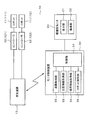
図1及び図2に示すように、ロボット安全システム10は、複数台のロボット11と、各ロボット11に対応して設けられたロボットコントローラ12と、安全装置13と、眼鏡型モニタ20と、モニタ制御装置30と、を含んで構成されている。本実施形態において、ロボット安全システム10は、2台のロボット11で構成されている。なお、以下の説明において、これら2台のロボット11を区別する際には、第1ロボット111及び第2ロボット112と称する。また、第1ロボットロボット111及び第2ロボット112に対応するロボットコントローラ12を、それぞれ第1ロボットコントローラ121及び第2ロボットコントローラ122と称する。
Hereinafter, an embodiment will be described with reference to the drawings.
As shown in FIGS. 1 and 2, the
ロボット11は、例えば6軸の垂直多関節型ロボットで構成されている。一般的な構成につき詳しい説明は省略するが、ロボット11は、サーボモータにより駆動される6軸のアームを有し、第6軸アームの先端部に、例えばパレット内に収容されているワークを把持するためのハンド等を備えている。ロボット11は、ロボットコントローラ12に図示しない接続ケーブルを介して接続される。各軸のサーボモータは、このロボットコントローラ12により制御される。
The
通常、各ロボット11には、危険距離と安全距離とが設定されている。危険距離及び安全距離は、図3に示すように、ロボット11を基準とした距離である。危険距離とは、ロボット11の可動距離D1に所定距離D2を加えた距離以下の距離である。安全距離とは、危険距離を越える距離である。所定距離D2は、ロボット11の動作速度等に応じて定められるものであり、例えばユーザが瞬時にロボット11に近づいても、ロボット11の可動距離D1には届かないような距離である。この場合、ロボット11を基準とした危険距離の内側の領域を危険領域と称する。また、ロボット11を基準とした危険距離の外側の領域を安全領域と称する。
Usually, a dangerous distance and a safe distance are set for each
ロボットコントローラ12は、図示しない制御回路やサーボ制御部、電源装置等を備えている。制御回路はマイコンを主体として構成されている。ロボットコントローラ12は、予め記憶された動作プログラムや、図示しないティーチングペンダント等により設定された教示データ、各種パラメータ等に従って、サーボ制御部を介してロボット11の各軸サーボモータを制御する。これにより、ロボットコントローラ12は、ワークの組付け作業等を各ロボット11に自動で実行させる。
The
各ロボットコントローラ12は、それぞれ安全装置13に通信可能に接続されている。安全装置13は、ロボットコントローラ12側から各ロボット11の動作状態及び各ロボットコントローラ12による制御状態を特定可能な各種の情報を取得可能に構成されている。そのため、安全装置13は、ロボット11のアームの回転角度やモータの通電状態等、ロボット11の動作状態を示す動作情報及びコントローラ12の制御状態を示す制御情報をリアルタイムで取得することができる。
Each
また、安全装置13は、各ロボットコントローラ12から取得した各ロボット11の情報に基づいて、ロボット11の現在の形態つまり姿勢を3次元的にモデリングした3Dモデル画像データを生成することができる。また、安全装置13は、各ロボット11が設置されている領域、例えば工場内における基準位置を原点とした2次元座標系における各ロボット11の座標つまりはロボット11の設置位置も記憶している。
Further, the
眼鏡型モニタ20は、一般的な眼鏡と同様にユーザが頭部に装着可能な形状に形成されている。眼鏡型モニタ20は、図2にも示すように、表示部21及び撮像部22を有している。表示部21は、眼鏡のレンズ部分に相当する部分であり、画像などの情報を表示することができるいわゆる透過型のディスプレイで構成されている。このため、眼鏡型モニタ20に表示される画像は、ユーザの視界に重なって表示されることになる。換言すると、ユーザは、自身の目で見た現実の風景と、眼鏡型モニタ20によって表示された仮想的な画像とを併せて見ることになる。
The glasses-
撮像部22は、小型のCCDカメラやCMOSカメラで構成されている。この撮像部22は、ユーザの顔の向きと一致するように、眼鏡型モニタ20のフレームの一測部に設けられている。撮像部22は、ユーザ100が眼鏡型モニタ20を頭部に装着した状態で、ユーザ100の頭部正面が向いている方向の画像を撮像する。そのため、撮像部22によって撮像される画像は、ユーザの視界とほぼ同一の画角となっている。換言すると、撮像部22は、ユーザが見ている風景とほぼ同一の風景を撮像する。
The
眼鏡型モニタ20は、モニタ制御装置30に無線又は有線で接続されている。モニタ制御装置30は、マイクロコンピュータ等で構成された制御部31を内蔵しており、眼鏡型モニタ20の表示部21に投影する画像データを送信したり、撮像部22により撮像された画像データを受信したりする。また、モニタ制御装置30は、安全装置13と有線又は無線通信が可能となっており、安全装置13から、上述した3Dモデル画像データを含む各ロボット11の動作状態を示す動作情報や、コントローラ12の制御状態を示す制御情報をリアルタイムで取得することがでる。
The eyeglass-
モニタ制御装置30は、図2に示すように、制御部31、距離取得部32、注意情報取得部33、視界情報取得部34、及びロボット識別部35を有している。制御部31は、マイクロコンピュータを主体に構成されており、ロボット安全システム用プログラムを記憶している。制御部31は、マイクロコンピュータにおいてロボット安全システム用プログラムを実行することにより、距離取得部32、注意情報取得部33、視界情報取得部34、及びロボット識別部35等を、ソフトウェア的に実現する。なお、これら距離取得部32、注意情報取得部33、視界情報取得部34、及びロボット識別部35は、例えば制御部31と一体の集積回路としてハードウェア的に実現してもよい。また、制御部31は、安全装置13側に設けられていてもよい。
As shown in FIG. 2, the
距離取得部32は、各ロボット11について、各ロボット11とユーザ100との距離Lxを取得する処理を行うことができる。なお、本実施形態では、ロボット111とユーザ100との距離Lxを距離L1とし、ロボット112とユーザ100との距離Lxを距離L2と示す。距離取得部32は、例えばユーザ100の位置情報に基づいて、各ロボット11とユーザ100との距離Lxを取得することができる。すなわち、距離取得部32は、例えば図4に示すように、各ロボット11が設置されている領域を2次元座標系とした各ロボット11の座標(X1、Y1)、(X2、Y2)を、安全装置13から取得する。そして、距離取得部32は、各ロボット11の座標(X1、Y1)、(X2、Y2)と、ユーザ100の座標(Xp、Yp)とから、各ロボット11とユーザ100との距離Lxを算出する。
The
ユーザ100の座標(Xp、Yp)つまりユーザの位置情報は、例えば眼鏡型モニタ20に小型のGPS(Global Positioning System)を設けることで取得することができる。また、ユーザの位置情報(Xp、Yp)は、GPSユニットのように直接的に位置を特定するものではなく、例えば工場の入り口等の基準位置からのユーザの移動軌跡を取得し、基準位置に対する変位量に基づいて間接的に位置を特定するような構成としてもよい。なお、図4及び図8において、ユーザ100から延び出た二点鎖線は、ユーザ100の視界を表している。
The coordinates (Xp, Yp) of the
図2に示す注意情報取得部33は、各ロボット11の注意情報を取得する処理を行うことができる。注意情報とは、各ロボット11に関する注意をユーザ100に促すための情報である。この注意情報は、ロボット11の動作状態を示す情報の一態様であり、安全装置13が取得した各ロボット11の動作状態等の情報に含まれている。そのため、注意情報取得部33は、安全装置13から各ロボット11の動作状態等の情報を取得することで、注意情報を取得することができる。注意情報は、例えばロボット11の運転状態、ロボット11とユーザ100との距離Lx、ロボット11のトルク、ロボット11の電源電圧等の情報である。この注意情報の内容は、ISO規格など標準規格に基づいて決定することができる。
The attention
視界情報取得部34は、ユーザの視界を特定するための視界情報を取得する処理を行うことができる。ユーザ100の視界とは、ユーザ100が眼鏡型モニタ20を装着した状態において、眼鏡のレンズ部分である表示部21を通してユーザ100の目に映る風景を意味する。視界情報取得部34は、撮像部22で撮像した画像から、ユーザ100の視界情報を取得する。すなわち、本実施形態では、撮像部22による撮像範囲を、ユーザ100の視界と擬制している。
The visual field information acquisition unit 34 can perform processing for acquiring visual field information for specifying the visual field of the user. The field of view of the
ロボット識別部35は、視界情報取得部34で取得した視界情報に基づいてユーザ100の視界内に存在するロボット11を識別する処理を行うことができる。すなわち、ロボット識別部35は、ユーザ100の視界内に存在するロボット11が、ロボット111、112のいずれであるかを識別つまり特定することができる。ロボット識別部35は、例えば次のようにして各ロボット11を識別することができる。すなわち、例えば各ロボット11に、それぞれ個体を特定するためのマーカーを付しておく。そして、ロボット識別部35は、撮像部22で撮像された画像を基にロボット11に付されたマーカーを認識することで、各ロボット11を識別することができる。
The
また、他の方法としては、ロボット識別部35は、例えば次のようにして各ロボット11を識別することができる。すなわち、ロボット識別部35は、安全装置13から各ロボット11の現在の3Dモデル画像データを取得する。そして、ロボット識別部35は、各ロボット11の3Dモデル画像データと、撮像部22で撮像されたロボット11の形態とを照合することで、各ロボット11を識別することができる。
As another method, the
制御部31は、各ロボット11とユーザ100との距離Lx、及び各ロボット11についての注意情報を、図5に示すようなシンボル表示41、及び図6に示すような詳細表示42によって、表示部21に表示させることができる。本実施形態の場合、シンボル表示41及び詳細表示42は、対象となるロボット11から吹き出されるように配置される吹き出し図形43内に配置されている。なお、この吹き出し図形43は、シンボル表示41及び詳細表示42には含まれない。
The
制御部31は、吹き出し図形43の内部に配置されるシンボル表示41又は詳細表示42の大きさや情報量に応じて適宜その吹き出し図形43の大きさを変更することができる。また、制御部31は、撮像部22で取得した画像からロボット11を抽出することで、吹き出し図形43を、各ロボット11に極力重ならないように表示させることができる。更に、制御部31は、複数の吹き出し図形43を同時に表示させる場合、これら複数の吹き出し図形43が相互に重ならないように表示させることができる。この場合、複数のロボット11について吹き出し図形43を表示させるときは、制御部31は、ユーザ100に近いロボット11及びそのロボット11の吹き出し図形43を優先して表示させる。また、例えば図7に示すように、詳細表示42とシンボル表示41とを同時に表示させる場合、制御部31は、シンボル表示41を詳細表示42よりも小さく表示する。
The
シンボル表示41は、ロボット11に関する注意情報が存在していることを示す表示である。シンボル表示41は、ユーザに与える情報量を極力少なくするため、3文字以上の文字列を有さない図記号で構成されている。本実施形態の場合、シンボル表示41は、例えばISO7010で標準化された一般危険を示すマークであり、三角形状の図形の内部に「!」の記号を付した図記号で構成されている。なお、シンボル表示41は、この図記号に限られない。例えば、「注」の1文字、又は「注意」の2文字の文字列を有する構成であってもよい。なお、本実施形態では、図形の内部に文字や記号が付されたものは、1つの図記号として扱う。
The
詳細表示42は、注意情報の詳細内容を示すものであり、注意情報の詳細を示す3文字以上の文字列や、この文字列に記号や図形等を併記したもので構成されている。例えば、図5に示す詳細表示42は、第1ロボット111に係る注意情報の詳細内容を示すものであり、停止中又は自動運転中など第1ロボット111の状態や、速度、ユーザ100との距離Lx、電源電圧、及びトルク等を示す3文字以上の文字列421を有して構成されている。
The
また、この文字列421に併記させる記号又は図形は、例えばISO7010で標準化された各種の危険を示す図記号である。例えば、図6の詳細表示42において、「速度:500mm/s」の文字列421に併記された図記号422は、「挟まれ注意」の意味を示し、図記号423は「ヘルメット要着用」の指示を意味する。また、詳細表示42において、「電源:200V」の文字列421に併記された図記号424は、「高電圧につき感電注意」の意味を示し、「トルク:65N」の文字列421に併記された図記号425は、「衝突注意」の意味を示す。
Further, the symbols or figures to be written in the
本実施形態の場合、各ロボット11に対して、シンボル表示41又は詳細表示42のいずれか一方が表示される。すなわち、本実施形態の場合、1つのロボット11に対して、シンボル表示41及び詳細表示42の両方が同時に表示されることはない。各ロボット11に係る注意情報をどのような態様で表示させるかは、図10に示すように、対象となるロボット11の動作状態、ユーザ100とロボット11との距離Lx、及びユーザ100の視界内に対象となるロボット11が存在するか否かによって決定される。ここで、複数のロボット11のうちユーザ100に最も近いロボット11つまりユーザ100との距離が最も短いロボット11を、最短ロボット11と称する。
In the case of the present embodiment, either the
まず、図10を参照して、最短ロボット11に係る注意情報の表示態様について説明する。最短ロボット11が動作中例えば自動運転中であって、かつ最短ロボット11とユーザ100との距離Lxが安全距離である場合、制御部31は、その最短ロボット11がユーザ100の視界内に存在していればシンボル表示41を表示させ、ユーザ100の視界内に存在していなければ何も表示させない。また、最短ロボット11が動作中であって、かつ最短ロボット11とユーザ100との距離Lxが危険距離である場合、制御部31は、最短ロボット11がユーザ100の視界内に存在するか否かに係わらず、詳細表示42を表示させる。
First, with reference to FIG. 10, the display mode of the caution information concerning the
一方、最短ロボット11が停止中であって、かつ最短ロボット11とユーザ100との距離Lxが安全距離である場合、制御部31は、最短ロボット11がユーザ100の視界内に存在するか否かに係わらず、詳細表示42を表示させない。そして、最短ロボット11が停止中であって、かつ最短ロボット11とユーザ100との距離Lxが危険距離である場合、制御部31は、最短ロボット11がユーザ100の視界内に存在するか否かに係わらず、詳細表示42を表示させる。
On the other hand, when the
次に、最短ロボット11以外のロボット11(以下、非最短ロボット11と称する)に係る注意情報の表示態様について説明する。非最短ロボット11が動作中であって、かつその非最短ロボット11とユーザ100との距離Lxが危険距離であって、かつその非最短ロボット11がユーザ100の視界内に存在していれば、制御部31は、非最短ロボット11の注意情報についてシンボル表示41を表示させる。一方、制御部31は、上記以外の場合は、非最短ロボット11の注意情報について何も表示させない。
Next, a display mode of caution information relating to a
また、制御部31は、色彩設定処理を実行することができる。色彩設定処理は、最短ロボット11の注意情報に係る詳細表示42を表示する場合、その最短ロボット11の現在の危険度に応じて、詳細表示42自体の色彩又は詳細表示42の周囲の領域の色彩を変更する処理である。本実施形態の場合、詳細表示42の周囲の領域は、吹き出し図形43の領域内を意味する。
Further, the
この場合、危険度とは、ユーザ100がロボット11に接近した場合にロボット11からユーザ100が受ける危険の程度を示す指標である。本実施形態の場合、危険度は、「低」と「高」との2値である。例えば、ロボット11が停止中又は自動運転中であっても低速で動作している場合、例えユーザ100がロボット11に接触したとしてもユーザ100が受ける影響は小さいため、この場合の危険度は「低」である。一方、ロボット11が自動運転中であって高速で動作している場合、ユーザ100がロボット11に接触した場合にユーザ100が受ける影響は大きいため、この場合の危険度は「高」である。なお、危険度は、ロボット11の仕様や動作内容等によって適宜変更することができる。
In this case, the degree of danger is an index indicating the degree of danger that the
本実施形態の場合、制御部31は、主に吹き出し図形43の領域内の色彩を、警告色と通常色との間で変更する。警告色とは、例えば黒色や赤色の暖色系の色彩、つまりユーザ100の注意を引き易い色彩である。通常色とは、例えば白色や青色の寒色系の色彩などであり、色彩環における警告色の反対色である。この場合、詳細表示42は、変更された吹き出し図形43の領域内の色彩に応じて見易い色彩に適宜変更される。
In the case of the present embodiment, the
具体例について、例えばユーザ100と各ロボット111、112との位置関係が図4のようになっている場合について見る。この場合、第1ロボット11は最短ロボット111であり、第2ロボット112は非最短ロボット112である。ここで、ユーザ100と最短ロボット111の距離L1が安全距離であれば、ユーザ100と非最短ロボット112との距離L2も必然的に安全距離となる。この場合、ロボット111、112共に動作中であれば、制御部31は、図5に示すように、最短ロボット111と非最短ロボット112との注意情報について、それぞれシンボル表示41を表示させる。一方、ロボット111、112共に停止中であれば、詳細は図示しないが、制御部31は、最短ロボット111と非最短ロボット112との注意情報について、それぞれ何も表示させない。
As a specific example, a case where the positional relationship between the
また、最短ロボット111と非最短ロボット112とが停止中であっても、ユーザ100と最短ロボット111の距離L1が危険距離であれば、制御部31は、図6に示すように、最短ロボット111の注意情報について詳細表示42を表示させる。この場合、制御部31は、停止中の非最短ロボット112の注意情報については何も表示させない。また、この場合、最短ロボット111の危険度は「低」であるため、制御部31は、吹き出し図形43の領域内を通常色で表示させる。
In addition, even when the
また、図6の状態から各ロボット111、112の自動運転が開始されると、制御部31は、最短ロボット111の注意情報について詳細表示42を表示させる。この場合、最短ロボット111の危険度は「高」であるため、制御部31は、図7に示すように、最短ロボット111の詳細表示42を有する吹き出し図形43の領域内を警告色で表示させる。また、この場合、非最短ロボット112とユーザ100との距離L2も危険距離であれば、制御部31は、非最短ロボット112の注意情報についてはシンボル表示41を表示させる。
When the automatic operation of the
更に、例えば図7の状態から図8に示すように、ユーザ100が向きを変えてユーザ100の視界が変化し、最短ロボット111がユーザ100の視界から外れた場合について見る。この場合、制御部31は、図9に示すように、最短ロボット111が存在する方向を指し示すようにして、最短ロボット111の注意情報に係る詳細表示42を表示させる。
Further, for example, as shown in FIG. 8 from the state of FIG. 7, the case where the
次に、制御部31で行われる処理について図11〜図13も参照して説明する。なお、以下の説明において、距離取得部32、注意情報取得部33、視界情報取得部34、及びロボット識別部35が行う処理は、全て制御部31で行う処理として説明する。
Next, processing performed by the
まず、図11に示すように、制御部31は、処理を開始すると(スタート)、ステップS11において距離取得処理を実行し、ユーザ100と各ロボット11との距離Lxを取得する。次に、制御部31は、ステップS12において注意情報取得処理を実行し、各ロボット11の注意情報を取得する。次に、制御部31は、ステップS13において視界情報取得処理を実行し、ユーザ100の視界情報を取得する。次に、制御部31は、ステップS14においてロボット識別処理を実行し、取得したユーザ100の視界情報に基づいて、そのユーザ100の視界内に存在するロボット11を識別する。
First, as illustrated in FIG. 11, when the process starts (start), the
次に、制御部31は、ステップS15において特定処理を実行する。特定処理では、制御部31は、ステップS11で取得した各ロボット11とユーザ100との距離Lxをそれぞれ比較して、最も距離Lxが短い最短ロボット11を特定する。次に、制御部31は、ステップS16において、ユーザ100と最短ロボット11との距離Lxが、安全距離であるか危険距離であるかを判断する。ユーザ100と最短ロボット11との距離Lxが危険距離であれば(ステップS16で危険距離)、制御部31は、ステップS20へ移行して色彩設定処理を実行する。
Next, the
制御部31は、ステップS20の色彩設定処理を実行すると、図12のステップS21において、最短ロボット11の危険度を判定する。危険度が「高」であれば(ステップS21で「高」)、制御部31は、ステップS22において詳細表示42に係る吹き出し図形43の領域内の色彩を警告色に設定する。一方、危険度が「高」であれば(ステップS21で「低」)、制御部31は、ステップS23において詳細表示42に係る吹き出し図形43の領域内の色彩を普通色に設定する。その後、制御部31は、図11のステップS17へ移行する。
When executing the color setting process of step S20, the
一方、ユーザ100と最短ロボット11との距離Lxが安全距離であれば(図11のステップS16で安全距離)、ユーザ100と非最短ロボット11との距離Lxも必然的に安全距離である。この場合、制御部31は、ステップS20を実行することなく、ステップS17へ移行する。そして、制御部31は、ステップS17において、図10に示した基準に基づいて、各ロボット11について詳細表示42又はシンボル表示41を表示させる。
On the other hand, if the distance Lx between the
その後、制御部31は、ステップS30において非表示処理を実行する。非表示処理は、ユーザ100と各ロボット11との距離Lxが一定期間以上変化していない場合つまりユーザ100が一定期間以上連続して停止している場合であって、かつユーザ100と最短ロボット11との距離Lxが安全距離である場合に、少なくともシンボル表示41を非表示にする処理である。本実施形態の場合、制御部31は、ユーザ100と各ロボット11との距離Lxが一定期間以上変化しない場合、表示中の詳細表示42及び全てのシンボル表示41を非表示にする。
Then, the
制御部31は、ステップS30において非表示処理を実行すると、図13の処理を実行する。この場合、制御部31は、まずステップS31において、ユーザ100が所定期間以上連続して停止しているか否かを判断する。制御部31は、ユーザ100が所定期間以上連続して停止している場合(ステップS31でYES)、ステップS32へ移行する。そして、制御部31は、ステップS32において、ユーザ100と最短ロボット11との距離Lxが安全距離であるか否かを判断する。
The
ユーザ100と最短ロボット11との距離Lxが安全距離である場合(ステップS32で安全距離)、制御部31は、表示中の詳細表示42及び全てのシンボル表示41を非表示にする。そして、制御部31は、図11のステップS11へ移行する(リターン)。一方、制御部31は、ユーザ100が所定期間の間に動きがあった場合(ステップS31でNO)、又はユーザ100と最短ロボット11との距離Lxが危険距離である場合(ステップS32で危険距離)、制御部31は、ステップS33を実行することなく、図11のステップS11へ移行する(リターン)。そして、制御部31は、ステップS11以降の処理を繰り返す。
When the distance Lx between the
このように、本実施形態のロボット安全システム10は、複数台のロボット11この場合2台のロボット11について各ロボット11とユーザ100との距離Lxを取得する距離取得部32と、ロボット11に関する注意をユーザ100に促すための注意情報を取得する注意情報取得部33と、ユーザ100が装着可能であってユーザ100の視界内に注意情報を表示可能な眼鏡型モニタ20と、眼鏡型モニタ20に対する表示内容を制御する制御部31と、を備える。
As described above, the
これによれば、ユーザ100は、自己の身体に装着した眼鏡型モニタ20、この場合、自己の頭部に装着した眼鏡型モニタ20を通して、複数台のロボット11の注意情報を確認することができる。したがって、例えユーザ100とロボット11との位置関係が変化しとしても、ユーザ100は、眼鏡型モニタ20に提示される情報によってロボット11の動作情報つまり注意情報を得ることができる。そのため、例えばロボット11に表示器を設けてその表示器に注意情報を表示させる場合に比べて、ロボット11に関する情報をユーザ100に確実に提示することができる。
According to this, the
ここで、眼鏡型モニタ20は、表示部21を通したユーザ100の視界内に注意情報を表示するため、複数台のロボット11に関する注意情報を同時に表示させようとすると、表示部21の表示領域内がその注意情報によって埋められるおそれがある。すると、ユーザ100の視界が注意情報によって塞がってしまい、現実のロボット11が目視できなくなって危険である。
Here, since the eyeglass-
つまり、装着型モニタ20を通して複数台この場合2台のロボット111、112を実際に目視しているユーザ100当人だけが、その複数台のロボット111、112に係る注意情報を得ることができる。この場合、そのユーザ100当人の一人だけでは、最短ロボット111以外の非最短ロボット112については同時に手当を行うことができない。そのため、非最短ロボット112に関する詳細情報は、ユーザ100にとっては現時点で必ずしも必要な情報ではなく、むしろ視界を邪魔するような存在となる。
That is, only the
そこで、本実施形態において、制御部31は、複数台のロボット111、112のうち、ユーザ100に最も近い位置のロボット11つまり最短ロボット111に関する注意情報については注意情報の詳細内容を示す詳細表示42を眼鏡型モニタ20の表示部21に表示させる。そして、制御部31は、ユーザ100に最も近い位置のロボット111以外のロボット112つまり非最短ロボット112に関する注意情報については、注意情報の存在を示すシンボル表示41を詳細表示42よりも小さい形態で眼鏡型モニタ20に表示させる。
Therefore, in the present embodiment, the
これによれば、最短ロボット111以外の非最短ロボット112に係る注意情報は、シンボル表示41として詳細表示42よりも小さく表示される。そのため、複数台のロボット11に関する注意情報を全て詳細表示42で表示させる場合に比べて、ユーザ100の視界に占める詳細表示42及びシンボル表示41の領域が小さくなる。すなわち、非最短ロボット112について詳細表示42が表示されないようにするということは、表示部21の表示領域内が優先度の低い詳細情報42によって埋められて、ユーザ100の視界が塞がれる危険性を低減することができるということである。そして、ユーザ100は、眼鏡型モニタ20に表示される詳細表示42を見ることで、少なくとも自己に最も近い最短ロボット111つまり接触等の危険性の最も高いロボット111についての注意情報の詳細内容を知ることができる。また、ユーザ100は、眼鏡型モニタ20に表示されるシンボル表示41を見ることで、最短ロボット111以外の非最短ロボット112について少なくとも注意情報が存在していることを知ることができる。
According to this, the attention information related to the
このように、ロボット安全システム10は、ユーザ100が装着可能な眼鏡型モニタ20を用いる場合において、ロボット11の注意情報に関して詳細表示42とシンボル表示41とを選択的に表示させる。これにより、ロボット安全システム10は、ユーザ100に提示する情報量を敢えて低減し、その情報が占める領域を低減することで、ユーザ100の視界が注意情報で埋まってしまうことを抑制することができる。これにより、ユーザ100は、眼鏡型モニタ20を通して、注意情報つまりシンボル表示41及び詳細表示42と、現実の風景とを同時に見易くなる。その結果、ロボット安全システム10は、眼鏡型モニタ20を用いた場合であっても、複数台のロボット11の動作状態に関する情報つまり注意情報を同時に見易くユーザ100に提示することができる。
As described above, the
ここで、最短ロボット111は、複数台のロボット112のうちユーザ100に最も接近しているロボット11である。そのため、ユーザ100は、最短ロボット111の動作状態について最も注意を払う必要がある。本実施形態によれば、最短ロボット111に係る詳細表示42は、他の非最短ロボット112に係るシンボル表示41よりも大きく表示される。したがって、ユーザ100の注意を最短ロボット111に係る詳細表示42に引き付けることができる。これにより、ユーザ100は、最短ロボット111の動作状態により注意を払うようになり、その結果、安全性が向上される。
Here, the
ロボット安全システム10は、ユーザ100の視界を特定するための視界情報を取得する視界情報取得部34と、視界情報取得部34で取得した視界情報に基づいてユーザ100の視界内に存在するロボット11を識別するロボット識別部35と、を更に備えている。そして、制御部31は、詳細表示42と当該詳細表示42に係る注意情報を有するロボット11つまり最短ロボット111とを極力重ならないように、眼鏡型モニタ20に表示させる。これによれば、少なくとも最短ロボット111がユーザ100の視界内に存在する場合、その最短ロボット111が詳細表示42によって隠れてしまうことを防ぐことができる。したがって、ユーザは、最短ロボット111と、その最短ロボット111の詳細表示42とを同時に目視し易くなり、その結果、視認性が向上する。
The
制御部31は、最短ロボット111について、ユーザ100と最短ロボット111との距離Lxが危険距離である場合には詳細表示42を眼鏡型モニタ20に表示させる。一方、制御部31は、ユーザ100と最短ロボット111との距離Lxが安全距離である場合には、シンボル表示41を眼鏡型モニタ20に表示させる。すなわち、複数台のロボット11のうちユーザ100に最も接近している最短ロボット111に対して安全距離が確保されていれば、全てのロボット11について安全距離が確保されているといえる。この場合、最短ロボット111の注意情報についても、詳細表示42に換えて詳細表示42よりも小さいシンボル表示41を表示させることで、ユーザ100の視界をより広く確保することができる。その結果、ユーザ100は、ロボット11等の目視がよりし易くなる。
When the distance Lx between the
ロボット安全システム10は、ユーザ100の視界を特定するための視界情報を取得する視界情報取得部34と、視界情報取得部34で取得した視界情報に基づいてユーザ100の視界内に存在するロボット11を識別するロボット識別部35と、を更に備える。そして、制御部31は、少なくとも詳細表示42が最短ロボット111に重ならないように詳細表示42を眼鏡型モニタ20に表示させる。これによれば、少なくとも最短ロボット111が、その最短ロボット111の詳細表示42によって隠れてしまうことを防ぐことができる。したがって、ユーザ100は、最短ロボット111と、その最短ロボット111の詳細表示42とを同時に目視し易くなり、その結果、視認性が向上する。
The
シンボル表示41は、3文字以上の文字列を有さない図記号で構成されている。これによれば、シンボル表示41の表示領域をより小さくすることができる。また、詳細表示42は、3文字以上の文字列を有して構成されている。これによれば、シンボル表示41に比べてユーザ100に提示することが可能な情報量をより多くすることができ、ユーザ100に対してロボット11の正確な動作状態つまり注意情報を提示することができる。
The
制御部31は、注意情報の内容に応じて詳細表示の色彩又は詳細表示の周囲の領域の色彩を変化させることができる。本実施形態の場合、制御部31は、注意情報の危険度つまりロボット11の危険度の高低に基づいて、吹き出し図形43内の領域の色彩を変更することができる。これによれば、注意情報の危険度に応じて、ユーザ100の注目度を変化させることができる。すなわち、ロボット11の危険度が高い場合には、吹き出し図形43内の領域を例えば赤色等の警告色にすることで、その吹き出し図形43内の詳細表示42にユーザ100の注意を引くことができる。その結果、安全性が更に向上される。
The
制御部31は、ユーザ100と各ロボット11との距離が一定期間以上変化せず、かつユーザ100と最短ロボット111との距離Lxが安全距離である場合に、少なくとも前記シンボル表示41を非表示にする。本実施形態の場合、ユーザ100と各ロボット11との距離が一定期間以上変化しない場合つまり一定期間ユーザ100に動きが無い場合で、かつユーザ100と最短ロボット111との距離Lxが安全距離である場合に、表示中の詳細表示42及び全てのシンボル表示41を非表示にする。
The
すなわち、ユーザ100と各ロボット11との距離Lxが一定期間以上変化しない状況とは、例えばユーザ100がその場に停止してロボット11の動作を観察している状況等が考えられる。この場合、ユーザ100と最短ロボット11との距離Lxが安全距離であって、ユーザ100の安全が確保されている状態であれば、詳細表示42等の情報を非表示としても特に問題は生じない。むしろ、詳細表示42等を非表示とすることで、ユーザ100の視界をより広く確保することができるため、ユーザ100のロボット11やロボット11の周辺に対する視認性が向上する。その結果、ユーザ100は、ロボット11やロボット11の周辺の観察がし易くなり、利便性の向上が図られる。
That is, the situation where the distance Lx between the
なお、本発明の実施形態は、上記し又図面に記載した態様に限定されるものではなく、その要旨を逸脱しない範囲で種々の変形や拡張をすることができる。
例えば各ロボット11側に人を検知するレーザセンサや人感センサ等を設けておき、それらのセンサの検出結果に基づいてユーザ100の位置を特定する構成としたり、センサの検出結果と撮像部22で撮像した画像とに基づいて位置を特定する構成としたり、撮像部22によって撮像された画像に基づいて各ロボット11に対する相対的な位置を特定する構成としたりしてもよい。
The embodiment of the present invention is not limited to the above-described embodiment and can be variously modified and extended without departing from the gist thereof.
For example, a laser sensor or a human sensor that detects a person is provided on each
制御部31、距離取得部32、注意情報取得部33、視界情報取得部34、及びロボット識別部35を、それぞれ安全装置13側又は眼鏡型モニタ20側に分散させて設けてもよい。
本実施形態において、対象とするロボット11の台数に制限は無いが、眼鏡型モニタ20に表示される情報量や一般的な人間が処理可能な情報量を考慮すると、対象とするロボット11の台数は5台程度までが好ましい。
ロボット11は、特定の場所に固定されているものに限られず、例えば自走可能な構成であってもよい。
眼鏡型モニタ20の表示部21は、透過型ディスプレイに限られない。装着型モニタ20の表示部21は、例えば不透過型のディスプレイであって、撮像部22で撮像した映像をユーザの視界としてリアルタイムで映し出すものでもよい。
そして、装着型モニタは、必ずしも眼鏡型モニタ20である必要はなく、作業者が頭部に装着するディスプレイに、画像を投影可能に構成されるものであれば良い。
The
In the present embodiment, the number of
The
The
The wearable monitor is not necessarily the glasses-
図面中、10はロボット安全システム、20は眼鏡型モニタ(装着型モニタ)、31は制御部、32は距離取得部、33は注意情報取得部、34は視界情報取得部、35はロボット識別部、41はシンボル表示、42は詳細表示を示す。 In the drawings, 10 is a robot safety system, 20 is an eyeglass monitor (wearable monitor), 31 is a control unit, 32 is a distance acquisition unit, 33 is a caution information acquisition unit, 34 is a view information acquisition unit, and 35 is a robot identification unit. , 41 is a symbol display, and 42 is a detailed display.
Claims (6)
前記ロボットに関する注意をユーザに促すための注意情報を取得する注意情報取得部と、
ユーザが装着可能であってユーザの視界内に前記注意情報を表示可能な装着型モニタと、
前記装着型モニタに対する表示内容を制御する制御部と、を備え、
前記制御部は、複数台の前記ロボットのうち、ユーザの最も近くに位置するロボットである最短ロボットに関する前記注意情報については前記注意情報の詳細内容を示す詳細表示を前記装着型モニタに表示させ、前記最短ロボット以外のロボットである非最短ロボットに関する前記注意情報については前記注意情報の存在を示すシンボル表示を前記詳細表示よりも小さい形態で前記装着型モニタに表示させる処理を行うことができる、
ロボット安全システム。 A distance acquisition unit for acquiring the distance between each robot and the user for a plurality of robots;
A caution information acquisition unit for acquiring caution information for prompting a user to pay attention regarding the robot;
A wearable monitor that can be worn by the user and can display the attention information in the user's field of view;
A control unit for controlling display contents for the wearable monitor,
The control unit causes the wearable monitor to display a detailed display indicating the detailed content of the caution information for the caution information regarding the shortest robot that is the closest robot to the user among the plurality of robots. With respect to the caution information regarding the non-shortest robot that is a robot other than the shortest robot, it is possible to perform processing for displaying a symbol display indicating the presence of the caution information on the wearable monitor in a form smaller than the detailed display.
Robot safety system.
請求項1に記載のロボット安全システム。 When the distance between the user and the shortest robot is a dangerous distance, the control unit displays the detailed display on the wearable monitor, and the distance between the user and the shortest robot is a safe distance. In some cases, the symbol display can be displayed on the wearable monitor.
The robot safety system according to claim 1.
前記視界情報取得部で取得した前記視界情報に基づいてユーザの視界内に存在する前記ロボットを識別するロボット識別部と、を更に備え、
前記制御部は、少なくとも前記詳細表示が前記最短ロボットに重ならないように前記詳細表示を前記装着型モニタに表示させる処理を行うことができる、
請求項1又は2に記載のロボット安全システム。 A view information acquisition unit for acquiring view information for identifying the user's view;
A robot identification unit that identifies the robot existing in the user's field of vision based on the field of vision information acquired by the field of vision information acquisition unit;
The control unit can perform a process of displaying the detailed display on the wearable monitor so that at least the detailed display does not overlap the shortest robot.
The robot safety system according to claim 1 or 2.
前記詳細表示は、3文字以上の文字列を有して構成されている、
請求項1から3のいずれか一項に記載のロボット安全システム。 The symbol display is composed of a graphic symbol having no character string of three characters or more,
The detailed display has a character string of three or more characters,
The robot safety system according to any one of claims 1 to 3.
請求項1から4のいずれか一項に記載のロボット安全システム。 The control unit can perform a process of changing the color of the detailed display or the color of the area around the detailed display according to the content of the caution information.
The robot safety system according to any one of claims 1 to 4.
請求項1から5のいずれか一項に記載のロボット安全システム。 The control unit performs a process of hiding at least the symbol display when the distance between the user and each robot does not change for a certain period or more and the distance between the user and the shortest robot is a safe distance. be able to,
The robot safety system according to any one of claims 1 to 5.
Priority Applications (1)
| Application Number | Priority Date | Filing Date | Title |
|---|---|---|---|
| JP2015233297A JP6645142B2 (en) | 2015-11-30 | 2015-11-30 | Robot safety system |
Applications Claiming Priority (1)
| Application Number | Priority Date | Filing Date | Title |
|---|---|---|---|
| JP2015233297A JP6645142B2 (en) | 2015-11-30 | 2015-11-30 | Robot safety system |
Publications (2)
| Publication Number | Publication Date |
|---|---|
| JP2017100206A true JP2017100206A (en) | 2017-06-08 |
| JP6645142B2 JP6645142B2 (en) | 2020-02-12 |
Family
ID=59016320
Family Applications (1)
| Application Number | Title | Priority Date | Filing Date |
|---|---|---|---|
| JP2015233297A Active JP6645142B2 (en) | 2015-11-30 | 2015-11-30 | Robot safety system |
Country Status (1)
| Country | Link |
|---|---|
| JP (1) | JP6645142B2 (en) |
Cited By (10)
| Publication number | Priority date | Publication date | Assignee | Title |
|---|---|---|---|---|
| JP6403920B1 (en) * | 2017-11-17 | 2018-10-10 | 三菱電機株式会社 | 3D space monitoring device, 3D space monitoring method, and 3D space monitoring program |
| JP2019187146A (en) * | 2018-04-13 | 2019-10-24 | 中国電力株式会社 | Warning image provision system |
| JP2019188531A (en) * | 2018-04-25 | 2019-10-31 | ファナック株式会社 | Simulation device of robot |
| JP2019188530A (en) * | 2018-04-25 | 2019-10-31 | ファナック株式会社 | Simulation device of robot |
| JP2019206050A (en) * | 2018-05-29 | 2019-12-05 | セイコーエプソン株式会社 | Control device, head-mounted display, and robot system |
| JP2020015128A (en) * | 2018-07-25 | 2020-01-30 | ファナック株式会社 | Sensing system, work system, extended reality image display method, extended reality image memorizing method, and program |
| WO2021039897A1 (en) * | 2019-08-30 | 2021-03-04 | Johnan株式会社 | Control device, control method, and program |
| US11049287B2 (en) | 2018-08-31 | 2021-06-29 | Fanuc Corporation | Sensing system, work system, augmented-reality-image displaying method, and program |
| CN114924513A (en) * | 2022-06-07 | 2022-08-19 | 中迪机器人(盐城)有限公司 | Multi-robot cooperative control system and method |
| JP7360406B2 (en) | 2018-06-26 | 2023-10-12 | ファナック アメリカ コーポレイション | Augmented reality visualization for robotic picking systems |
Citations (11)
| Publication number | Priority date | Publication date | Assignee | Title |
|---|---|---|---|---|
| JPS5697387A (en) * | 1979-12-29 | 1981-08-06 | Matsushita Electric Works Ltd | Operation display system for disaster prevention system |
| JPH01140298A (en) * | 1987-11-26 | 1989-06-01 | Matsushita Electric Works Ltd | Disaster preventing system |
| JP2001052271A (en) * | 1999-08-10 | 2001-02-23 | Nohmi Bosai Ltd | Disaster preventive display device |
| JP2004243516A (en) * | 2003-02-11 | 2004-09-02 | Kuka Roboter Gmbh | Method for fading-in information created by computer into image of real environment, and device for visualizing information created by computer to image of real environment |
| JP2009040108A (en) * | 2007-08-06 | 2009-02-26 | Denso Corp | Image display control device and image display control system |
| WO2011080882A1 (en) * | 2009-12-28 | 2011-07-07 | パナソニック株式会社 | Operating space presentation device, operating space presentation method, and program |
| JP2011227879A (en) * | 2010-03-30 | 2011-11-10 | Ns Solutions Corp | Information providing device, information providing method, and program |
| JP2012003462A (en) * | 2010-06-16 | 2012-01-05 | Toshiba Corp | Information terminal, launcher program and method |
| WO2013118191A1 (en) * | 2012-02-10 | 2013-08-15 | 三菱電機株式会社 | Driving assistance device and driving assistance method |
| JP2014096057A (en) * | 2012-11-09 | 2014-05-22 | Sharp Corp | Image processing apparatus |
| JP2015049842A (en) * | 2013-09-04 | 2015-03-16 | トヨタ自動車株式会社 | Alert display device and alert display method |
-
2015
- 2015-11-30 JP JP2015233297A patent/JP6645142B2/en active Active
Patent Citations (11)
| Publication number | Priority date | Publication date | Assignee | Title |
|---|---|---|---|---|
| JPS5697387A (en) * | 1979-12-29 | 1981-08-06 | Matsushita Electric Works Ltd | Operation display system for disaster prevention system |
| JPH01140298A (en) * | 1987-11-26 | 1989-06-01 | Matsushita Electric Works Ltd | Disaster preventing system |
| JP2001052271A (en) * | 1999-08-10 | 2001-02-23 | Nohmi Bosai Ltd | Disaster preventive display device |
| JP2004243516A (en) * | 2003-02-11 | 2004-09-02 | Kuka Roboter Gmbh | Method for fading-in information created by computer into image of real environment, and device for visualizing information created by computer to image of real environment |
| JP2009040108A (en) * | 2007-08-06 | 2009-02-26 | Denso Corp | Image display control device and image display control system |
| WO2011080882A1 (en) * | 2009-12-28 | 2011-07-07 | パナソニック株式会社 | Operating space presentation device, operating space presentation method, and program |
| JP2011227879A (en) * | 2010-03-30 | 2011-11-10 | Ns Solutions Corp | Information providing device, information providing method, and program |
| JP2012003462A (en) * | 2010-06-16 | 2012-01-05 | Toshiba Corp | Information terminal, launcher program and method |
| WO2013118191A1 (en) * | 2012-02-10 | 2013-08-15 | 三菱電機株式会社 | Driving assistance device and driving assistance method |
| JP2014096057A (en) * | 2012-11-09 | 2014-05-22 | Sharp Corp | Image processing apparatus |
| JP2015049842A (en) * | 2013-09-04 | 2015-03-16 | トヨタ自動車株式会社 | Alert display device and alert display method |
Cited By (21)
| Publication number | Priority date | Publication date | Assignee | Title |
|---|---|---|---|---|
| JP6403920B1 (en) * | 2017-11-17 | 2018-10-10 | 三菱電機株式会社 | 3D space monitoring device, 3D space monitoring method, and 3D space monitoring program |
| WO2019097676A1 (en) * | 2017-11-17 | 2019-05-23 | 三菱電機株式会社 | Three-dimensional space monitoring device, three-dimensional space monitoring method, and three-dimensional space monitoring program |
| CN111372735A (en) * | 2017-11-17 | 2020-07-03 | 三菱电机株式会社 | 3-dimensional space monitoring device, 3-dimensional space monitoring method, and 3-dimensional space monitoring program |
| JP2019187146A (en) * | 2018-04-13 | 2019-10-24 | 中国電力株式会社 | Warning image provision system |
| JP7059770B2 (en) | 2018-04-13 | 2022-04-26 | 中国電力株式会社 | Warning image providing system |
| CN110394779A (en) * | 2018-04-25 | 2019-11-01 | 发那科株式会社 | The simulator of robot |
| JP2019188531A (en) * | 2018-04-25 | 2019-10-31 | ファナック株式会社 | Simulation device of robot |
| CN110394780B (en) * | 2018-04-25 | 2023-06-27 | 发那科株式会社 | Simulation device of robot |
| CN110394780A (en) * | 2018-04-25 | 2019-11-01 | 发那科株式会社 | The simulator of robot |
| JP2019188530A (en) * | 2018-04-25 | 2019-10-31 | ファナック株式会社 | Simulation device of robot |
| US11220002B2 (en) | 2018-04-25 | 2022-01-11 | Fanuc Corporation | Robot simulation device |
| US11192249B2 (en) | 2018-04-25 | 2021-12-07 | Fanuc Corporation | Simulation device for robot |
| JP7187820B2 (en) | 2018-05-29 | 2022-12-13 | セイコーエプソン株式会社 | Controllers, head-mounted displays, and robot systems |
| JP2019206050A (en) * | 2018-05-29 | 2019-12-05 | セイコーエプソン株式会社 | Control device, head-mounted display, and robot system |
| JP7360406B2 (en) | 2018-06-26 | 2023-10-12 | ファナック アメリカ コーポレイション | Augmented reality visualization for robotic picking systems |
| US10885340B2 (en) | 2018-07-25 | 2021-01-05 | Fanuc Corporation | Sensing system, work system, augmented-reality-image displaying method, augmented-reality-image storing method, and program |
| JP2020015128A (en) * | 2018-07-25 | 2020-01-30 | ファナック株式会社 | Sensing system, work system, extended reality image display method, extended reality image memorizing method, and program |
| US11328507B2 (en) | 2018-07-25 | 2022-05-10 | Fanuc Corporation | Sensing system, work system, augmented-reality-image displaying method, augmented-reality-image storing method, and program |
| US11049287B2 (en) | 2018-08-31 | 2021-06-29 | Fanuc Corporation | Sensing system, work system, augmented-reality-image displaying method, and program |
| WO2021039897A1 (en) * | 2019-08-30 | 2021-03-04 | Johnan株式会社 | Control device, control method, and program |
| CN114924513A (en) * | 2022-06-07 | 2022-08-19 | 中迪机器人(盐城)有限公司 | Multi-robot cooperative control system and method |
Also Published As
| Publication number | Publication date |
|---|---|
| JP6645142B2 (en) | 2020-02-12 |
Similar Documents
| Publication | Publication Date | Title |
|---|---|---|
| JP6645142B2 (en) | Robot safety system | |
| CN106808496B (en) | Robot safety system | |
| US10474411B2 (en) | System and method for alerting VR headset user to real-world objects | |
| US20210170603A1 (en) | Method for using a multi-link actuated mechanism, preferably a robot, particularly preferably an articulated robot, by a user by means of a mobile display apparatus | |
| JP6491574B2 (en) | AR information display device | |
| US10712566B2 (en) | Information displaying system provided with head-mounted type display | |
| EP3163407B1 (en) | Method and apparatus for alerting to head mounted display user | |
| US20180136716A1 (en) | Method for operating a virtual reality system, and virtual reality system | |
| JP2017100207A (en) | Robot safety system | |
| US11148299B2 (en) | Teaching apparatus and teaching method for robots | |
| JP6589604B2 (en) | Teaching result display system | |
| JP6582921B2 (en) | Robot monitor system | |
| JP6657858B2 (en) | Robot operation system | |
| JP2017102242A (en) | Information display system | |
| US10359840B2 (en) | Method for operating a virtual reality system, and virtual reality system | |
| JP6834620B2 (en) | Information display system | |
| US10684480B2 (en) | Information display system | |
| JP6874448B2 (en) | Information display system | |
| JP2022122936A (en) | Information display system | |
| JP6631203B2 (en) | Virtual fence display system | |
| JP6690203B2 (en) | Robot safety system | |
| JP6958018B2 (en) | Information display system | |
| CN115079973A (en) | Display system and display device | |
| KR101975556B1 (en) | Apparatus of controlling observation view of robot | |
| JP2021011017A (en) | Display system for robot |
Legal Events
| Date | Code | Title | Description |
|---|---|---|---|
| A621 | Written request for application examination |
Free format text: JAPANESE INTERMEDIATE CODE: A621 Effective date: 20180621 |
|
| A977 | Report on retrieval |
Free format text: JAPANESE INTERMEDIATE CODE: A971007 Effective date: 20190529 |
|
| A131 | Notification of reasons for refusal |
Free format text: JAPANESE INTERMEDIATE CODE: A131 Effective date: 20190611 |
|
| A521 | Request for written amendment filed |
Free format text: JAPANESE INTERMEDIATE CODE: A523 Effective date: 20190809 |
|
| TRDD | Decision of grant or rejection written | ||
| A01 | Written decision to grant a patent or to grant a registration (utility model) |
Free format text: JAPANESE INTERMEDIATE CODE: A01 Effective date: 20191210 |
|
| A61 | First payment of annual fees (during grant procedure) |
Free format text: JAPANESE INTERMEDIATE CODE: A61 Effective date: 20191223 |
|
| R150 | Certificate of patent or registration of utility model |
Ref document number: 6645142 Country of ref document: JP Free format text: JAPANESE INTERMEDIATE CODE: R150 |
|
| R250 | Receipt of annual fees |
Free format text: JAPANESE INTERMEDIATE CODE: R250 |
|
| R250 | Receipt of annual fees |
Free format text: JAPANESE INTERMEDIATE CODE: R250 |