JP2017100164A - Manufacturing method of very small thin wall substantially cylindrical body - Google Patents
Manufacturing method of very small thin wall substantially cylindrical body Download PDFInfo
- Publication number
- JP2017100164A JP2017100164A JP2015236147A JP2015236147A JP2017100164A JP 2017100164 A JP2017100164 A JP 2017100164A JP 2015236147 A JP2015236147 A JP 2015236147A JP 2015236147 A JP2015236147 A JP 2015236147A JP 2017100164 A JP2017100164 A JP 2017100164A
- Authority
- JP
- Japan
- Prior art keywords
- thin
- cylindrical body
- substantially cylindrical
- refraction
- shape
- Prior art date
- Legal status (The legal status is an assumption and is not a legal conclusion. Google has not performed a legal analysis and makes no representation as to the accuracy of the status listed.)
- Pending
Links
Images


Abstract
Description
本発明は、電極、装飾品、医療用カテーテルや注射針等に好適に使用できる金属材料において、この金属材料を用いた薄板材を筒状に曲げ、その対向する両端縁部を嵌合した微小薄肉略円筒体の製造方法に関する。 The present invention relates to a metal material that can be suitably used for electrodes, ornaments, medical catheters, injection needles, and the like, in which a thin plate material using this metal material is bent into a cylindrical shape and the opposite end edges thereof are fitted to each other. The present invention relates to a method for manufacturing a thin substantially cylindrical body.
貴金属材料を用いた微小薄肉略円筒体は、装飾品、MEMSやコンタクトプローブ分野における電極、血管等の体内管状組織に対して検査や治療等を行うための医療器具の一部として医療用カテーテルや注射針等、幅広い産業分野に使用されている(例えば、特許文献1)。 A thin thin cylindrical body using a noble metal material is used as a medical catheter as a part of a medical instrument for inspecting or treating an in-vivo tubular tissue such as an ornament, an electrode in the field of MEMS and contact probes, and a blood vessel. It is used in a wide range of industrial fields such as injection needles (for example, Patent Document 1).
例えば、医療用カテーテルには、狭心症や心筋梗塞などの血管狭窄部において、狭窄部を貫通させる貫通用カテーテル、狭窄部の拡張に用いるバルーンを備えたバルーンカテーテル、狭窄部を治療する際にガイドワイヤやバルーンを血管内に導くためのガイドカテーテル、狭窄部の血栓等を除去する吸引カテーテル等が知られている。 For example, in a medical catheter, in a vascular stenosis part such as angina pectoris or myocardial infarction, a penetrating catheter that penetrates the stenosis part, a balloon catheter equipped with a balloon used to expand the stenosis part, and when treating a stenosis part A guide catheter for guiding a guide wire or a balloon into a blood vessel, a suction catheter for removing a thrombus or the like in a stenosis, and the like are known.
これらの医療用カテーテルには、化学的安定性やX線不透過性などに優れることから貴金属系材料を用いた円筒状のX 線不透過マーカーが固着されている。 Since these medical catheters are excellent in chemical stability and radiopacity, a cylindrical radiopaque marker using a noble metal material is fixed.
これらの医療用カテーテルによる手技は、通常はX線照射を行いながら行い、X線不透過マーカーによりカテーテルやガイドワイヤの位置や角度を把握し、狭窄部へ誘導する。 The procedures using these medical catheters are usually performed while X-ray irradiation is performed, and the positions and angles of the catheter and the guide wire are grasped by an X-ray impermeable marker and guided to the stenosis.
医療用カテーテルに用いられる円筒のX線不透過マーカーには、マーカーの内面がカテーテル内腔やガイドワイヤ腔に隣接しているものもある。通常、この内面はポリマー等の被覆により平滑な面となっており、手技者がガイドワイヤの繊細な操作を行う際の抵抗を極力抑制した構造となっている (例えば、特許文献2)。 Some cylindrical radiopaque markers used in medical catheters have the inner surface of the marker adjacent to the catheter lumen or guidewire cavity. Usually, this inner surface is a smooth surface by coating with a polymer or the like, and has a structure in which the resistance when the operator performs a delicate operation of the guide wire is suppressed as much as possible (for example, Patent Document 2).
この微小かつ薄肉の円筒状X線不透過マーカーの作製方法としては、例えば、プラグ引き、空引きや芯引き加工などの伸管方法が挙げられる(例えば、特許文献3〜4)。
Examples of a method for producing this minute and thin cylindrical X-ray opaque marker include tube drawing methods such as plug drawing, empty drawing and core drawing (for example,
プラグ引き加工は、内外面の面粗度を平滑にする点では優れているが、薄肉になると加工引抜力に耐えられずに破断や変形が生じやすく、薄肉円筒体の伸管方法としては困難である。 Plug drawing is excellent in terms of smoothing the surface roughness of the inner and outer surfaces, but if it is thin, it will not be able to withstand the drawing force and will tend to break or deform, making it difficult as a method of extending a thin cylindrical body. It is.
一方、空引きや芯引き加工は、円筒体内面に多数のシワや被りによる凹凸を発生させる場合がある。加えて、円筒体の最大長さは伸管装置の大きさに左右され、多数のダイスパスを要する長い伸管工程となるために細管化に伴う伸管工数増大はいうまでもなく、被りの剥離による脱落やその凹凸部への異物混入の危険性を排除するための検査工数が必要となる上に、内面であるが故に外観からの発見や除去がさらに困難となる。 On the other hand, emptying or centering may cause unevenness due to numerous wrinkles and coverings on the inner surface of the cylindrical body. In addition, the maximum length of the cylindrical body depends on the size of the tube drawing device, and since it is a long tube drawing process that requires a large number of die passes, it goes without saying that the number of tube drawing man-hours increases due to the narrowing of the tube, and the covering is peeled off. In addition to the need for inspection man-hours to eliminate the risk of falling off and contamination of the concavo-convex portion, it is more difficult to find and remove from the appearance because of the inner surface.
さらに、量産される円筒状X線不透過マーカーは医療用カテーテルにかしめ加工によって固着されるが、円筒体にかしめ加工を施すということは、必然的に円筒体外面もしくは内面にシワを生じさせるために、隣接する被覆対象との間に空隙ができてしまい、均一な固着が困難となる。さらに、円筒体素材自体の内面に多数のシワや被りによる凹凸がある場合には、その固着力の不安定性はより顕著なものとなる。 Furthermore, mass-produced cylindrical radiopaque markers are fixed to a medical catheter by caulking. However, caulking the cylindrical body inevitably causes wrinkles on the outer surface or inner surface of the cylindrical body. In addition, a gap is formed between adjacent objects to be coated, and uniform fixing becomes difficult. Furthermore, when there are many wrinkles and irregularities due to covering on the inner surface of the cylindrical material itself, the instability of the fixing force becomes more remarkable.
従って、固着不足のものが多少の確率で発生するのが避けられないが、その固着力の検査は医療用カテーテルに損傷をもたらすので現実的に不可能となる。さらに、その固着力不足から、手技中に血管内で脱落する恐れがないとはいえず、安全面で問題がある。 Therefore, it is unavoidable that a thing with insufficient adhesion is generated with a certain probability, but the examination of the adhesion force is practically impossible because it causes damage to the medical catheter. Furthermore, it cannot be said that there is no risk of dropping off in the blood vessel during the procedure due to the lack of fixing force, which is problematic in terms of safety.
このように、医療用カテーテルに用いられる円筒状のX線不透過マーカーには、内面が平滑であり、かつ高い固着力が求められている。 Thus, a cylindrical X-ray opaque marker used for a medical catheter is required to have a smooth inner surface and a high fixing force.
また、市場では安価な円筒体が求められている。 In addition, an inexpensive cylindrical body is required in the market.
本発明は、高い固着力を有し、内面が平滑でしかも安価である微小薄肉円筒体の製造方法を提供することを目的とする。 An object of the present invention is to provide a method for producing a thin thin cylindrical body having a high fixing force, a smooth inner surface and being inexpensive.
そこで本発明は、金属薄板の短尺側両端部と長尺側両端縁部が直角状でなく、金属薄板の短尺側両端部相互が対向して接続固定されていない自由端1であり、自由端縁相互が対応して嵌合可能な大略クランク形状を有する微小薄肉略円筒体とした。なお、微小薄肉略円筒体を被覆対象にかしめ加工するために、かしめ加工前においてはこの自由端相互が離隔した形状の微小薄肉略円筒体であってもよい。
Therefore, the present invention is a
ここで、本発明の自由端における大略クランク形状とは、一方の自由端が合計で2以上の偶数回の屈折3、4を繰り返し、奇数番目の屈折に相当する群と、偶数番目の屈折に相当する群において、同じ群に属する屈折は同じ方向へ屈折するものと定義する。
Here, the approximate crank shape at the free end of the present invention means that one free end repeats even number of
つまり、2つの自由端は偶数回の屈折をするが、偶数番目における屈折群と奇数番目における屈折群は、それぞれの群で同じ方向へ屈折し、対向する自由端縁相互が互いに平行した方向へ屈折した形状となる。ただし、この屈折回数には、微小薄肉略円筒体の長さ方向両端の略円周部から自由端1へ屈折する両始点2a、2bは含まないものとする。さらに、この屈折回数は、2以上の偶数であれば特に上限はない。また、この屈折回数は、微小薄肉略円筒体の長さ方向両端の略円周端部6側において、どちらか一方の略円周端部側から数えるものとする。
That is, the two free ends refract an even number of times, but the even-numbered refraction group and the odd-numbered refraction group are refracted in the same direction in each group, and the opposing free edges are parallel to each other. It becomes a refracted shape. However, the number of refractions does not include both
微小薄肉略円筒体を被覆対象へのかしめ加工後において、屈折回数が多いほど、自由端相互が位置ずれすることを防止する効果が高くなることにより、被覆対象への嵌合力が高まる。 After caulking a thin thin substantially cylindrical body onto the object to be coated, the greater the number of refractions, the higher the effect of preventing the displacement of the free ends from each other, thereby increasing the fitting force to the object to be coated.
なお、各屈折点の角度としては、直角もしくは鈍角であることが好ましい。これは、度数法で90°未満になると各屈折点3、4に曲げやカケが生じやすくなるためであり、屈折角が180°になると直線となってしまいクランク形状ではなくなってしまうためである。上記範囲内であれば、微小薄肉略円筒体を被覆対象へのかしめ加工後において、屈折角が鋭角に近づくほど、被覆対象への嵌合力が高まり、自由端相互が位置ずれすることを防止する効果が高くなる。
The angle of each refraction point is preferably a right angle or an obtuse angle. This is because bending and chipping are likely to occur at each of the
なお、各屈折点3、4の角度は全て同一でなくても良く、奇数番目に相当する群と偶数番目に相当する群の間で相違してもよい。
The angles of the
また、各屈折点3、4においては曲げやカケ等を防止するためにR加工やC面取りを施してもよいし、自由端相互においては篏合をより精密に密閉にするために相似して組み合わさるテーパー加工を施してもよい。
Further, at each of the
本発明の微小薄肉略円筒体は、自由端縁相互が対応して嵌合するクランク形状であるが、この自由端相互が微小薄肉略円筒体の略円周端部6と成す角度に関しては、度数法で90°よりも小さく45°以上であることが好ましい。この角度を90°よりも小さくした理由は、微小薄肉略円筒体同士の絡まり防止をするとともに、自由端相互が嵌合する距離と面積を大きくすることで嵌合力を高めるためである。
The small thin-walled substantially cylindrical body of the present invention has a crank shape in which the free ends correspond to each other, but regarding the angle formed by the free ends with the substantially
ここで、微小薄肉略円筒体同士の絡まりとは、量産時には多数の微小薄肉略円筒体が製造される為に、微小薄肉略円筒体同士が接触して混在した環境下に置かれる場合がある。 Here, the entanglement between minute thin-walled substantially cylindrical bodies means that a large number of minute thin-walled substantially cylindrical bodies are manufactured in mass production, and therefore, there are cases where the minute thin-walled substantially cylindrical bodies are placed in an environment where they are in contact with each other. .
この際に、微小薄肉略円筒体の自由端相互が離隔した形状であると、この離隔部同士がクランク形状の屈折部まで絡まる状態が多発する。この状態は、角度90°のときは離隔幅5を有する離隔部がクランク形状の屈折部3、4まで侵入して絡まるが、自由端を円筒端部に対して傾斜を付与することで円筒端部にて侵入が抑えられ、結果として絡まり防止となる。
At this time, if the free ends of the minute thin-walled substantially cylindrical body are separated from each other, a state in which the separated portions are entangled with the crank-shaped refracting portion frequently occurs. In this state, when the angle is 90 °, the separation portion having the separation width 5 enters the crank-shaped refracting
なお、この角度が45°未満であっても絡まり防止の効果は得られるが、微小薄肉略円筒体の長さ方向両端の略円周端部から自由端へ屈折する始点2bの一部における角度も45°未満となり、始点2bに曲げやカケが生じやすくなる。
Even if this angle is less than 45 °, the effect of preventing entanglement can be obtained, but the angle at the part of the
自由端1相互間の離隔幅5は、被覆対象の大きさにより適宜調整でき、かしめ加工を施した被覆後において自由端同士が隙間無く近接して篏合できる幅が最も好ましい。
The separation width 5 between the
しかし、微小薄肉略円筒体の内径よりも大きな線状の被覆対象へ微小薄肉略円筒体を被覆する場合もある。この場合は、被覆対象の線径を、被覆後における離隔幅で除した百分率(以下、離隔率とする)において、25%未満とするように被覆前の離隔幅5を調整することが好ましい。25%未満の範囲では、金属薄板材の弾性力により数値が大きくなるにつれて被覆対象への篏合力が高まるが、25%以上になると強い曲げや伸び等によって被覆対象から脱落する場合があり、逆に負の値となると自由端相互が衝突してカケや曲りが生じる場合があるためである。 However, the thin thin substantially cylindrical body may be coated on a linear covering object larger than the inner diameter of the thin thin substantially cylindrical body. In this case, it is preferable to adjust the separation width 5 before coating so that the percentage of the wire diameter of the coating object divided by the separation width after coating (hereinafter referred to as the separation ratio) is less than 25%. In the range of less than 25%, as the numerical value increases due to the elastic force of the metal thin plate material, the joining force to the coating target increases. However, if it exceeds 25%, it may fall off from the coating target due to strong bending or elongation. This is because if the negative value is negative, the free ends may collide with each other to cause chipping or bending.
本発明の微小薄肉略円筒体に関して、微小とは外径φ6mm以下、薄肉とは肉厚100μm以下のことをいい、長さに関しては特に制限はない。 With regard to the minute thin-walled substantially cylindrical body of the present invention, the fine means an outer diameter of 6 mm or less, the thin means a thickness of 100 μm or less, and the length is not particularly limited.
金属薄板の材質としては、使用用途により適宜選択された公知のものであればどのような金属材料でも良いが、X線不透過性や化学的安定性、薄板化や略円筒体への成形加工性に優れる点で、好ましくはAu、PtおよびPdの群から選ばれた1種の純金属、より好ましくはIr、Ni、Re、Rh、RuおよびWの群から選ばれた少なくとも1種を0.1〜30質量%含み、残部(Balance)がAu、PtおよびPdの群から選ばれた1種と不可避不純物からなる貴金属合金がよい。 As the material of the metal thin plate, any known metal material may be used as long as it is appropriately selected depending on the intended use. However, X-ray impermeability, chemical stability, thinning, and forming into a substantially cylindrical body are possible. In view of excellent properties, it is preferable that one pure metal selected from the group of Au, Pt and Pd, more preferably at least one selected from the group of Ir, Ni, Re, Rh, Ru and W be 0 A noble metal alloy containing 1 to 30% by mass, the balance being selected from the group consisting of Au, Pt and Pd and inevitable impurities is preferable.
金属薄板は、鍛造加工等によっても作製可能だが、平滑な表面状態とする為には、電解箔や圧延加工が特に好ましい。電解箔や圧延加工は、使用する電極ロールや圧延ロールの面粗度によって、加工対象素材の表面粗さが大きく左右されるため、平滑なロールを使用するほどに平滑な素材となる。また、板材であるので、求められる表面粗さに応じてバフ研磨等の研磨処理を施すことで、さらに平滑にすることができ、かつ異物混入の危険性を低減することができる。 Although the metal thin plate can be produced by forging or the like, electrolytic foil or rolling is particularly preferable in order to obtain a smooth surface state. Since the surface roughness of the material to be processed is greatly affected by the surface roughness of the electrode roll or rolling roll used, the electrolytic foil or rolling process becomes a smooth material as the smooth roll is used. Moreover, since it is a board | plate material, according to the surface roughness calculated | required, it can be made further smooth by performing grinding | polishing processes, such as buffing | polishing, and the danger of a foreign material mixing can be reduced.
上記手段によって得られた金属薄板にプレス加工を施して、微小薄肉略円筒体へ成形することで、略円筒体の外内面が平滑なものとなる。 By pressing the thin metal plate obtained by the above means and forming it into a thin thin substantially cylindrical body, the outer inner surface of the substantially cylindrical body becomes smooth.
金属薄板における加工率の選定は、プレス加工によって作製される際の微小薄肉略円筒体の外径、肉厚、長さ、表面、粗さ、バリ、ダレそれぞれの寸法とその公差を考慮したうえで決定されるが、本発明においては、金属薄板材の加工率を断面減少率で10%〜99%とした。この理由は、10%未満であると板材の平坦度が悪く、プレス加工時の成形において略円筒状の形状が崩れるためである。99%を超えてしまうと、金属薄板材に残った加工ひずみの影響で略円筒状の形状が崩れるためである。 When selecting the processing rate for thin metal plates, consider the outer diameter, thickness, length, surface, roughness, burrs and sagging dimensions and tolerances of the thin thin cylindrical body produced by pressing. However, in the present invention, the processing rate of the thin metal plate material is 10% to 99% in terms of the cross-sectional reduction rate. The reason for this is that if it is less than 10%, the flatness of the plate material is poor, and the substantially cylindrical shape collapses during molding during pressing. This is because if it exceeds 99%, the substantially cylindrical shape collapses due to the processing strain remaining on the thin metal plate.
なお、上記のごとく、用いられる金属薄板材は加工率を断面減少率で10%〜99%の範囲としたことにより、これをプレス加工するに際して、プレス加工で得られる略円筒状材料の円周両端部のバリ、ダレ等の発生を低減させている。また、金属薄板材に適切な熱処理後にプレス加工することにより、プレス加工時のバリ、ダレの発生を低減させることもできる。 As described above, the metal thin plate material used has a processing rate in the range of 10% to 99% in terms of the cross-sectional reduction rate. When this is pressed, the circumference of the substantially cylindrical material obtained by pressing is approximately The occurrence of burrs and sagging at both ends is reduced. Further, by performing press processing after an appropriate heat treatment on the metal thin plate material, it is possible to reduce the occurrence of burrs and sagging during the press processing.
本発明の微小薄肉略円筒体によると、自由端相互が対応して嵌合するクランク形状としたことで、かしめ加工時に円筒体外面もしくは内面にシワが生じることがなく、被覆対象全周を均一に包み込むことが可能となり、固着力強度の向上効果が得られる。また、平滑な表面状態の薄板から略円筒体へ直接成形が可能なため、その内外面は平滑なものとなり、より安定的な固着力が得られる。 According to the thin thin substantially cylindrical body of the present invention, the crank shape in which the free ends are correspondingly fitted together does not cause wrinkles on the outer surface or inner surface of the cylinder during caulking, and the entire circumference of the coating target is uniform. It is possible to wrap it in the film, and the effect of improving the strength of fixing force can be obtained. Further, since a thin plate having a smooth surface state can be directly molded into a substantially cylindrical body, the inner and outer surfaces thereof are smooth, and a more stable fixing force can be obtained.
また、実質的に制限のない長尺の薄板から略円筒体へ、連続的かつ多数の直接成形可能であるため、安価な円筒体が提供可能となる。 In addition, since a large number of thin plates that are substantially unlimited can be formed directly into a substantially cylindrical body continuously and in large numbers, an inexpensive cylindrical body can be provided.
さらに、金属薄板材からプレス加工により、目標寸法へ直接的に成形することにより、製作工程を削減することによるコストを低減させると共に板材の作製可能な板厚であれば、従来は作製困難であった薄肉の円筒状材料の作製も可能となる。 In addition, it is difficult to produce a sheet material that can be produced by pressing the metal sheet directly into the target dimensions by pressing, thereby reducing the cost by reducing the number of production steps and producing a sheet material. It is also possible to produce a thin cylindrical material.
以下に本発明の実施例を説明する。なお、本発明の実施形態は、下記の実施例に限定されるものではなく、目的とする材料の寸法や特性により適宜調整することができるものである。 Examples of the present invention will be described below. In addition, embodiment of this invention is not limited to the following Example, It can adjust suitably with the dimension and characteristic of the target material.
所望組成になるよう配合と溶解によりインゴットを得た後、鍛造、面削、焼鈍および圧延加工を施して板厚1.2mmの金属板材を作製した。その後、焼鈍および精密圧延を繰り返し、最終加工率が断面減少率で90%である板厚25μmの金属薄板を作製した。 After obtaining an ingot by blending and melting so as to have a desired composition, forging, chamfering, annealing and rolling were performed to produce a metal plate material having a plate thickness of 1.2 mm. Thereafter, annealing and precision rolling were repeated to produce a metal thin plate with a plate thickness of 25 μm having a final processing rate of 90% in terms of cross-sectional reduction rate.
次に、この金属薄板を用いたプレス加工の第1段階として、金属薄板の長尺側両端部が対応するクランク形状となるよう成形した(図1)。この際、必要に応じてクランク形状には傾斜を付与する。 Next, as a first stage of the press working using the metal thin plate, the metal thin plate was molded so that both ends on the long side had a corresponding crank shape (FIG. 1). At this time, the crank shape is inclined as necessary.
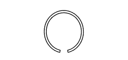
プレス加工の第2段階として、二つの半円筒体が並んだ状態で連なった大略m形体に曲折成形(図2)する。プレス加工の第3段階として、半円筒体の両端縁を対向するようにつき合わせることで、外径φ0.65mm×内径φ0.60mm、肉厚25μm、長さ1mmの寸法であって、かつ金属薄板の長尺側両端部相互が対向して接続固定されていない自由端であり、この自由端相互が対応して嵌合可能なクランク形状からなる微小薄肉略円筒体を得た(図3、図4、図5)。
As a second stage of the press working, bending is formed into a substantially m-shaped body in which two semi-cylindrical bodies are arranged side by side (FIG. 2). As the third stage of the press working, the both ends of the semi-cylindrical body are aligned so as to face each other, so that the outer diameter φ0.65 mm × the inner diameter φ0.60 mm, the wall thickness 25 μm, the
この微小薄肉略円筒体は、自由端におけるクランク形状の屈折回数は2、自由端相互間の離隔幅0.12mm、自由端相互における各屈折点の角度は120°、自由端相互が微小薄肉略円筒体の略円周端部と成す角度を80°とした。各々の微小薄肉略円筒体の材質、微小薄肉略円筒体の内面における表面粗さRaを表1に示す。 This small thin-walled substantially cylindrical body has a crank-shaped refraction number of 2 at the free end, a separation width of 0.12 mm between the free ends, an angle of each refraction point between the free ends of 120 °, and the free ends are substantially thin. The angle formed with the substantially circumferential end of the cylindrical body was 80 °. Table 1 shows the material of each thin thin substantially cylindrical body and the surface roughness Ra on the inner surface of the small thin substantially cylindrical body.

従来例として、実施例と同様に板厚1.2mmの金属板厚を作製した。その後、金属板材を筒状に巻いて継ぎ目を溶接し、ダイスと芯金を用いて所定の形状に伸管加工後、短尺に切断し、外径φ0.65mm×内径φ0.60mm、肉厚25μm、長さ1mmの微小薄肉略円筒体を得た。各々の微小薄肉略円筒体の材質、微小薄肉略円筒体の内面における表面粗さRaを表1に併記する。
自由端相互が微小薄肉略円筒体の略円周端部と成す角度、屈折回数と各屈折点の角度(奇数番目と偶数番目の群で同一もしくは相違)を変更した以外は実施例1における表1の微小薄肉略円筒体種類No.1(材質:Pt)と同様にして、微小薄肉略円筒体を各100個作製した。これら100個の微小薄肉略円筒体を65×90のポリ袋内に封入し、超音波洗浄機にて10分間振動させた後の微小薄肉略円筒体同士の絡まりの発生数を調査した。この調査結果を表2に示す。 The table in Example 1 except that the angle between the free ends and the substantially circumferential end of the small thin-walled substantially cylindrical body, the number of refractions, and the angle of each refraction point (same or different for odd and even groups) were changed. 100 fine thin substantially cylindrical bodies were produced in the same manner as in No. 1 fine thin substantially cylindrical body type No. 1 (material: Pt). These 100 thin thin substantially cylindrical bodies were sealed in a 65 × 90 plastic bag, and the number of occurrences of entanglement between the thin thin substantially cylindrical bodies after being vibrated for 10 minutes by an ultrasonic cleaner was investigated. The survey results are shown in Table 2.
固着強度(空隙発生固体数)の調査は、微小薄肉略円筒体を取り付けた樹脂チューブ各100点に引張試験機を用いて定変化量で引張りおよび3点曲げを行った後、微小薄肉略円筒体と樹脂チューブ間に空隙が生じた固体数を目視および超音波探傷器にて確認することで行った。また、この固着強度の調査時に、曲げや欠けが生じた固体は、破損発生個体数として分類して調査した。各調査条件の種類を調査種類No.として表2に併記する。 The investigation of the bond strength (number of voids generated solids) was conducted by pulling 100 points of each resin tube with a small thin-walled approximately cylindrical body using a tensile tester with a constant change amount and bending at three points, and then forming a thin-walled approximately cylindrical body. The number of solids in which voids were generated between the body and the resin tube was confirmed visually and with an ultrasonic flaw detector. Further, at the time of investigating the adhesion strength, the solids in which bending or chipping occurred were classified and investigated as the number of breakage individuals. The types of survey conditions are listed in Table 2 as survey types.
なお、他の材質(微小薄肉略円筒体No.2〜25)においても同様の調査を行ったところ、自由端相互が微小薄肉略円筒体の略円周端部と成す角度による絡まりの発生数の増減傾向、固着強度(空隙発生固体数)の増減傾向や破損発生個体数の増減傾向に差異はなかった。 The same investigation was conducted on other materials (small thin-walled approximately cylindrical body No. 2 to 25), and the number of occurrences of entanglement due to the angle between the free ends and the substantially circumferential end of the minute thin-walled approximately cylindrical body. There was no difference in the tendency of increase / decrease, the tendency of increase / decrease of the adhesion strength (number of solids generated by voids), and the tendency of increase / decrease in the number of fractures.
様々な外径の樹脂チューブへのかしめ加工した以外は、実施例2における表2の調査種類No.8と同様にして、空隙発生固体数を調査した。また、この調査時に離隔率と樹脂チューブからの脱落個体数についても調査した。これらの調査結果を表3に記載する。 Except for caulking to resin tubes having various outer diameters, the number of voids generated was investigated in the same manner as in investigation type No. 8 in Table 2 in Example 2. In addition, the separation rate and the number of individuals dropped from the resin tube were also investigated during this survey. These survey results are listed in Table 3.
1 自由端
2a 始点
2b 始点(自由端相互が微小薄肉略円筒体の略円周端部と成す角度)
3 屈折(奇数番目)
4 屈折(偶数番目)
5 離隔幅
6 略円周端部
1
3 Refraction (odd number)
4 Refraction (even number)
5
Claims (5)
2つの半円筒が連なった状態の断面形状が大略m形へ成形する第2プレス工程と、
金属薄板の短尺側両端部相互が対向して接続固定されていない2つの自由端となり、この自由端相互のクランク形状が対応して嵌合可能な略円筒へ成形する第3プレス工程を含む微小薄肉略円筒体の製造方法。 The angle formed between the short side ends of the metal thin plate and the long side ends is not a right angle, and the shape of the short side ends is a total of two or more times of refraction, and the group corresponding to the odd number of refractions. In the group corresponding to the even-numbered refraction, the first press step of forming a refraction belonging to the same group into a crank shape refracted in the same direction;
A second pressing step in which the cross-sectional shape of the two half-cylinders connected to each other is formed into a substantially m shape
A small amount including a third pressing step in which the short side ends of the metal thin plate face each other to form two free ends that are not connected and fixed, and the crank shapes of the free ends are correspondingly fitted into a substantially cylindrical shape. A method for producing a thin cylindrical body.
Priority Applications (1)
| Application Number | Priority Date | Filing Date | Title |
|---|---|---|---|
| JP2015236147A JP2017100164A (en) | 2015-12-02 | 2015-12-02 | Manufacturing method of very small thin wall substantially cylindrical body |
Applications Claiming Priority (1)
| Application Number | Priority Date | Filing Date | Title |
|---|---|---|---|
| JP2015236147A JP2017100164A (en) | 2015-12-02 | 2015-12-02 | Manufacturing method of very small thin wall substantially cylindrical body |
Publications (1)
| Publication Number | Publication Date |
|---|---|
| JP2017100164A true JP2017100164A (en) | 2017-06-08 |
Family
ID=59016250
Family Applications (1)
| Application Number | Title | Priority Date | Filing Date |
|---|---|---|---|
| JP2015236147A Pending JP2017100164A (en) | 2015-12-02 | 2015-12-02 | Manufacturing method of very small thin wall substantially cylindrical body |
Country Status (1)
| Country | Link |
|---|---|
| JP (1) | JP2017100164A (en) |
Cited By (1)
| Publication number | Priority date | Publication date | Assignee | Title |
|---|---|---|---|---|
| WO2021111864A1 (en) * | 2019-12-03 | 2021-06-10 | 株式会社Tokuda-Ard | Injection needle manufacturing method |
-
2015
- 2015-12-02 JP JP2015236147A patent/JP2017100164A/en active Pending
Cited By (1)
| Publication number | Priority date | Publication date | Assignee | Title |
|---|---|---|---|---|
| WO2021111864A1 (en) * | 2019-12-03 | 2021-06-10 | 株式会社Tokuda-Ard | Injection needle manufacturing method |
Similar Documents
| Publication | Publication Date | Title |
|---|---|---|
| JP6361651B2 (en) | Stent, manufacturing method and manufacturing apparatus thereof | |
| EP2581104A1 (en) | Medical tube, and manufacturing method for same | |
| JP2011167387A (en) | Guidewire | |
| JP4963326B2 (en) | Guide wire | |
| EP2163276A1 (en) | Guide wire | |
| JP2003136142A (en) | Metallic tubular member and method for manufacturing metallic tubular member | |
| JP2008011867A (en) | Dilator, method of manufacturing dilator, and sheath introducer | |
| JP5080094B2 (en) | Continuation of catheter tube and method for manufacturing catheter tube | |
| JP2017100164A (en) | Manufacturing method of very small thin wall substantially cylindrical body | |
| US20120253319A1 (en) | Guidewire | |
| JP2017099725A (en) | Substantially cylindrical body with micro-thin wall | |
| JP2016130351A (en) | Cylindrical material and manufacturing method for the same | |
| JPWO2010101142A1 (en) | Core wire for guide wire and manufacturing method thereof | |
| JP5268183B2 (en) | Titanium long fiber and method for producing the same | |
| JP2011125556A (en) | Guide wire | |
| JP2008212947A (en) | Composite material manufacturing method and apparatus | |
| JP5388619B2 (en) | Ultrasound endoscope puncture needle and manufacturing method thereof | |
| JP4592061B2 (en) | Injection needle, injection needle manufacturing method, and injection needle manufacturing apparatus | |
| CN115996775A (en) | Pipe | |
| JP5467777B2 (en) | Ultrasound endoscope puncture needle and manufacturing method thereof | |
| CN110193130B (en) | Guide wire | |
| JP2016094656A (en) | Cylindrical material and method for producing the same | |
| JP6297814B2 (en) | Metal porous body | |
| CN115348879B (en) | Guide wire | |
| US11617883B2 (en) | Multilayer ring electrode having a plurality of openings |