JP2017091202A - Object recognition method and object recognition device - Google Patents
Object recognition method and object recognition device Download PDFInfo
- Publication number
- JP2017091202A JP2017091202A JP2015220314A JP2015220314A JP2017091202A JP 2017091202 A JP2017091202 A JP 2017091202A JP 2015220314 A JP2015220314 A JP 2015220314A JP 2015220314 A JP2015220314 A JP 2015220314A JP 2017091202 A JP2017091202 A JP 2017091202A
- Authority
- JP
- Japan
- Prior art keywords
- angle
- unit
- model
- edge
- information recording
- Prior art date
- Legal status (The legal status is an assumption and is not a legal conclusion. Google has not performed a legal analysis and makes no representation as to the accuracy of the status listed.)
- Pending
Links
Images


Abstract
Description
この発明は、画像から抽出したエッジ(ライン)を鍵として物体の認識を行う物体認識方法及び物体認識装置に関するものである。 The present invention relates to an object recognition method and an object recognition apparatus for recognizing an object using an edge (line) extracted from an image as a key.
生産工程を効率化する手段として、バラ積み状態で置かれた物体(部品等)を自動で認識してロボットに把持させるビンピッキング技術が注目されており、近年、様々な方法が提案されている(例えば特許文献1−3参照)。このようなビンピッキング技術において、従来の物体認識では、モデルテンプレートを用いた画像マッチング又は一般化ハフ変換による投票手法等を用いている。 Bin picking technology that automatically recognizes objects (parts, etc.) placed in a piled-up state and grips them by a robot is attracting attention as a means of improving the production process. In recent years, various methods have been proposed. (For example, refer to Patent Documents 1-3). In such bin picking technology, in conventional object recognition, a voting method based on image matching using a model template or generalized Hough transform is used.
しかしながら、従来のモデルテンプレートを用いた画像マッチング又は一般化ハフ変換による投票手法等による物体認識では、画像平面内での回転及び移動も考慮して物体の位置及び姿勢を特定する必要がある。そのため、解空間が広く、膨大な回数の試行及び投票を繰り返す必要があり、現状では時間短縮が難しい上に認識率も高くない。 However, in object recognition based on a conventional voting method using image matching or generalized Hough transform using a model template, it is necessary to specify the position and orientation of an object in consideration of rotation and movement in the image plane. For this reason, the solution space is wide, and it is necessary to repeat a large number of trials and voting. At present, it is difficult to shorten the time and the recognition rate is not high.
また、局所濃淡画像と距離画像を併用した高速化手法も提案されているが、濃淡特徴が強く現れている物体にしか対応できず、更に、画像平面内における回転も含めて物体の姿勢を変更した膨大な数の実画像モデルを作成する必要がある等実用上の問題がある。 In addition, a high-speed method using both a local grayscale image and a distance image has been proposed, but it can only deal with objects with strong grayscale features, and the posture of the object can be changed, including rotation in the image plane. There is a practical problem such as the need to create a huge number of real image models.
また、従来の物体認識手法では、対称形状の物体を用いたり、物体同士が複雑に絡み合うことのない条件で用いたりしていることが多い。それに対して、バラ積み状態での物体認識では、物体の重なり及び絡みによる画像処理の難しさ、物体の位置及び姿勢を推定するための探索の困難さを有している。 Further, in the conventional object recognition method, a symmetrical object is often used, or the object is used under a condition that the objects do not complicatedly intertwine. On the other hand, object recognition in a stacked state has difficulty in image processing due to overlapping and entanglement of objects, and difficulty in searching for estimating the position and orientation of the object.
この発明は、上記のような課題を解決するためになされたもので、従来構成に対して、簡易な手法で、物体認識の効率化及び高速化を図ることができる物体認識方法及び物体認識装置を提供することを目的としている。 The present invention has been made in order to solve the above-described problems. An object recognition method and an object recognition apparatus capable of increasing the efficiency and speeding up of object recognition by a simple method compared to the conventional configuration. The purpose is to provide.
この発明に係る物体認識方法は、モデル情報記録部が、仮想カメラにより物体の三次元モデルが撮影されて生成された投影像である物体モデルの、エッジの角度の相対関係及び当該エッジの位置の相対関係を示す情報を記録するモデル情報記録ステップと、画像取得部が、画像を取得する画像取得ステップと、エッジ抽出部が、画像取得部により取得された画像からエッジを抽出するエッジ抽出ステップと、角度検出部が、エッジ抽出部により抽出されたエッジの角度を検出する角度検出ステップと、角度判定部が、角度検出部により検出された角度の中から、モデル情報記録部に記録された角度の相対関係との一致率が閾値以上である角度を検索し、当該検索した角度に対応する物体モデルを当該モデル情報記録部から抽出する角度判定ステップと、位置検出部が、角度判定部により検索された角度に対応するエッジの位置を検出する位置検出ステップと、位置判定部が、位置検出部により検出された位置の中から、モデル情報記録部に記録された位置の相対関係との一致率が閾値以上である位置を検索し、当該検索した位置に対応する物体モデルを当該モデル情報記録部から抽出する位置判定ステップと、物体認識部が、角度判定部及び位置判定部により抽出された物体モデルの中から、当該角度判定部及び当該位置判定部により検索された角度及び位置とモデル情報記録部に記録された角度及び位置の相対関係との一致率が総合的に高いものを物体として認識する物体認識ステップとを有するものである。 In the object recognition method according to the present invention, the model information recording unit is configured to detect the relative relationship between the angle of the edge and the position of the edge of the object model, which is a projection image generated by capturing a three-dimensional model of the object with a virtual camera. A model information recording step for recording information indicating a relative relationship, an image acquisition step for the image acquisition unit to acquire an image, and an edge extraction step for the edge extraction unit to extract an edge from the image acquired by the image acquisition unit; The angle detection step in which the angle detection unit detects the angle of the edge extracted by the edge extraction unit, and the angle recorded in the model information recording unit from the angles detected by the angle detection unit by the angle determination unit An angle determination process is performed to search for an angle having a matching rate with a relative relationship of a threshold value equal to or greater than a threshold, and extract an object model corresponding to the searched angle from the model information recording unit. A position detection step in which the position detection unit detects the position of the edge corresponding to the angle searched by the angle determination unit, and the position determination unit detects model information from the positions detected by the position detection unit. A position determination step of searching for a position where the matching rate with the relative relationship of the positions recorded in the recording unit is equal to or greater than a threshold, and extracting an object model corresponding to the searched position from the model information recording unit; and an object recognition unit Is the relative relationship between the angle and position retrieved by the angle determination unit and the position determination unit from the object model extracted by the angle determination unit and the position determination unit, and the angle and position recorded in the model information recording unit. And an object recognition step for recognizing an object having a generally high matching rate as an object.
また、この発明に係る物体認識装置は、仮想カメラにより物体の三次元モデルが撮影されて生成された投影像である物体モデルの、エッジの角度の相対関係及び当該エッジの位置の相対関係を示す情報を記録するモデル情報記録部と、画像を取得する画像取得部と、画像取得部により取得された画像からエッジを抽出するエッジ抽出部と、エッジ抽出部により抽出されたエッジの角度を検出する角度検出部と、角度検出部により検出された角度の中から、モデル情報記録部に記録された角度の相対関係との一致率が閾値以上である角度を検索し、当該検索した角度に対応する物体モデルを当該モデル情報記録部から抽出する角度判定部と、角度判定部により検索された角度に対応するエッジの位置を検出する位置検出部と、位置検出部により検出された位置の中から、モデル情報記録部に記録された位置の相対関係との一致率が閾値以上である位置を検索し、当該検索した位置に対応する物体モデルを当該モデル情報記録部から抽出する位置判定部と、角度判定部及び位置判定部により抽出された物体モデルの中から、当該角度判定部及び当該位置判定部により検索された角度及び位置とモデル情報記録部に記録された角度及び位置の相対関係との一致率が総合的に高いものを物体として認識する物体認識部とを有するものである。 In addition, the object recognition device according to the present invention shows the relative relationship between the edge angle and the relative position of the edge of the object model, which is a projection image generated by photographing a three-dimensional model of the object with a virtual camera. A model information recording unit that records information, an image acquisition unit that acquires an image, an edge extraction unit that extracts an edge from an image acquired by the image acquisition unit, and an angle of the edge extracted by the edge extraction unit From the angles detected by the angle detection unit and the angle detection unit, an angle having a matching rate with the relative relationship of the angles recorded in the model information recording unit is greater than or equal to a threshold value, and corresponds to the retrieved angle. An angle determination unit that extracts an object model from the model information recording unit, a position detection unit that detects the position of an edge corresponding to the angle searched by the angle determination unit, and a position detection unit The position where the matching rate with the relative relation of the position recorded in the model information recording unit is greater than or equal to the threshold is searched from the extracted positions, and the object model corresponding to the searched position is retrieved from the model information recording unit. From the position determination unit to be extracted, the angle determination unit and the object model extracted by the position determination unit, the angle and position searched by the angle determination unit and the position determination unit, and the angle recorded in the model information recording unit And an object recognizing unit for recognizing an object having a high matching rate with the relative relationship of positions as an object.
この発明によれば、上記のように構成したので、従来構成に対して、簡易な手法で、物体認識の効率化及び高速化を図ることができる。 According to this invention, since it comprised as mentioned above, the efficiency and speeding-up of object recognition can be achieved with a simple method compared with the conventional structure.
以下、この発明の実施の形態について図面を参照しながら詳細に説明する。
実施の形態1.
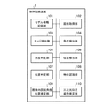
図1はこの発明の実施の形態1に係る物体認識装置1の構成例を示す図である。
物体認識装置1は、画像から抽出したエッジ52を鍵として物体51を認識する機能と、認識した物体51の三次元空間における位置及び姿勢を推定する機能とを有するものである。この物体認識装置1は、モデル情報記録部101、画像取得部102、エッジ抽出部103、角度検出部104、角度判定部105、位置検出部106、位置判定部107、物体認識部108、画像内回転角度位置推定部109及び三次元位置姿勢推定部110を備えている。なお、物体認識装置1は、ソフトウェアに基づくCPUを用いたプログラム処理によって実行される。
Hereinafter, embodiments of the present invention will be described in detail with reference to the drawings.
Embodiment 1 FIG.
FIG. 1 is a diagram showing a configuration example of an object recognition apparatus 1 according to Embodiment 1 of the present invention.
The object recognition device 1 has a function of recognizing an
モデル情報記録部101は、物体モデル51bのエッジ52bの角度の相対関係及び当該エッジ52bの位置の相対関係を示す情報を記録するものである。なお、位置の相対関係については、同一の角度のエッジ52b毎に記録を行う。
ここで、物体モデル51bは、仮想カメラ50bによって物体51の三次元モデル51aが様々な姿勢(画像平面内における回転及び移動以外の姿勢)で撮影されて生成された投影像である。また、仮想カメラ50bとしては、実際に物体認識を行う際に物体51の撮影に用いられるカメラ50と同一の焦点距離を有するものを用いる。
The model
Here, the
また、モデル情報記録部101は、物体モデル51bのエッジ52bの角度(基準軸からの絶対角度)、及び、当該物体モデル51bに対応する三次元モデル51aが撮影された際の当該三次元モデル51aの仮想カメラ50bからの距離及び三次元空間における姿勢を示す情報も記録している。また、モデル情報記録部101は、物体51の三次元モデル51aの三次元空間における任意の点(端、重心、中央の点等)を物体51の三次元空間における位置を表現するための基準点として設定し、画像上の物体モデル51bへの基準点の投影点53bを算出して、同一の角度のエッジ52b毎に、当該エッジ52bから見た基準点の画像上における投影点53bの方向を示す情報も記録している。
このモデル情報記録部101は、HDD、DVD、メモリ等によって構成される。
The model
The model
画像取得部102は、画像を取得するものである。この際、画像取得部102は、例えばバラ積み状態の物体(部品等)51をカメラ50で撮影した画像を取得する。
The
エッジ抽出部103は、画像取得部102により取得された画像からエッジ52を抽出するものである。この際、エッジ抽出部103は、上記画像からハフ変換又はその他のラインセグメント抽出法によりエッジ52を抽出する。
The
角度検出部104は、エッジ抽出部103により抽出されたエッジ52の角度を検出するものである。またこの際、角度検出部104は、検出した角度のうち、値の近いものを同一の角度としてまとめる。
The
角度判定部105は、角度検出部104により検出された角度の中から、モデル情報記録部101に記録された角度の相対関係との一致率(評価値)が閾値以上である角度を検索し、当該検索した角度に対応する物体モデル51bを当該モデル情報記録部101から抽出するものである。
The
位置検出部106は、角度判定部105により検索された角度に対応するエッジ52の位置を検出するものである。この際、位置検出部106は、角度判定部105により検索された同一の角度毎に、対応するエッジ52を投影軸(当該角度方向に対する垂線)54に画像平面内で投影した位置を、上記エッジ52の位置として検出する。
The
位置判定部107は、位置検出部106により検出された位置の中から、モデル情報記録部101に記録された位置の相対関係との一致率(評価値)が閾値以上である位置を検索し、当該検索した位置を持つ物体モデル51bを当該モデル情報記録部101から抽出するものである。
The
物体認識部108は、角度判定部105及び位置判定部107により抽出された物体モデル51bの中から、当該角度判定部105及び当該位置判定部107により検索された角度及び位置とモデル情報記録部101に記録された角度及び位置の相対関係との一致率が総合的に高いものを物体51として認識するものである。この際、物体認識部108は、例えば、角度の一致率(評価値)と位置の一致率(評価値)との合計が最も高い物体モデル51bを物体51として認識する。
The
画像内回転角度位置推定部109は、物体認識部108により認識された物体51のエッジ52の角度及びエッジ52の位置から、当該物体51の画像平面内における物体モデル51bに対する回転角度及び画像平面内における位置を推定するものである。この際、画像内回転角度位置推定部109は、物体認識部108により認識された物体51のエッジ52の角度を、モデル情報記録部101に記録された物体モデル51bの対応するエッジ52bの角度と比較し、そのずれ量から当該物体51の画像平面内における物体モデル51bに対する回転角度を推定する。また、モデル情報記録部101に記録された投影点53bの方向を示す情報から、物体認識部108により認識された物体51での、同一の角度のエッジ52毎の投影点53の方向の交点を算出し、その交点から画像平面内での物体51の位置を推定する。
The in-image rotation angle
三次元位置姿勢推定部110は、画像内回転角度位置推定部109により推定された物体51の回転角度及び位置、及び、物体認識部108により物体51と認識された物体モデル51bに関するモデル情報記録部101に記録された対応する三次元モデル51aの仮想カメラ50bからの距離及び三次元空間における姿勢から、当該物体51の三次元空間における位置及び姿勢を推定するものである。
The three-dimensional position /
この際、三次元位置姿勢推定部110は、モデル情報記録部101に記録された物体モデル51bに対応する三次元モデル51aと仮想カメラ50bとの撮影時の三次元位置関係を参照し、画像内回転角度位置推定部109により推定された物体51の画像平面内における位置から、三次元空間における当該物体51の位置を推定する。
At this time, the three-dimensional position /
更に、モデル情報記録部101に記録された物体モデル51bに対応する三次元モデル51aを撮影した際の三次元空間における姿勢(仮想カメラ50bから見た三次元モデル51aの姿勢)を画像内回転角度位置推定部109により推定された回転角度だけカメラ軸周りに回転する。次いで、推定した物体51の三次元空間における位置に対応する姿勢の回転補正を行う。この一連の座標変換により、物体51の三次元空間における姿勢を推定する。
Further, the orientation in the three-dimensional space (the orientation of the three-
次に、上記のように構成された物体認識装置1の動作例について、図2〜12を用いて説明する。以下では、図3に示す形状の物体51を認識する場合を例に説明を行う。
従来のモデルテンプレートを用いた画像マッチング又は一般化ハフ変換による投票手法等による物体認識では、物体51の三次元空間内での位置及び姿勢の変化に対応する大量の投影モデルを用意し、図3に示すような画像平面(カメラ50で撮影した実際の物体51の画像)内での物体51の見かけの回転及び移動に対しても照合を行うため、探索空間が増大する。そこで、本発明では、画像平面内で物体51が回転又は移動している場合であっても、見た目がほぼ同じであれば同じ物体モデル51bを使って照合及び認識することで、探索空間の増大を回避する。すなわち、物体51の見た目が変わらない場合には、物体51の投影像を構成するエッジの角度の相対関係及びエッジの位置の相対関係はほぼ変わらないことを利用する。
Next, an operation example of the object recognition device 1 configured as described above will be described with reference to FIGS. Hereinafter, a case where the
In object recognition by a conventional voting method using image matching or generalized Hough transform using a model template, a large number of projection models corresponding to changes in the position and orientation of the
なお、画像を撮影するカメラ50と認識対象である物体51との距離が近すぎるとカメラ50の奥行き方向の投影ひずみが増大するため、本発明はカメラ50と物体51との距離を適切に離して使用する。
Note that if the distance between the camera 50 that captures an image and the
本発明では、事前に、図4に示すように仮想カメラ50bによって物体51の三次元モデル51aが様々な姿勢(画像平面内における回転及び移動以外の姿勢)で撮影されて、図5に示すような投影像(物体モデル51b)が生成される。そして、図6に示すように、モデル情報記録部101(モデル情報記録ステップ)では、物体モデル51bのエッジ52bの角度の相対関係及び当該エッジ52bの位置の相対関係を示す情報を記録している。この際、エッジ52bの角度の相対関係については、上記物体モデル51bが持つ複数のエッジ52bに対して基準軸からの角度を求め、それらの角度(θ0,θ1,・・・,θi)を角度分布(図8の上段に示す角度分布)として集めて記録する。また、エッジ52bの位置の相対関係については、上記物体モデル51bが持つ複数のエッジ52bに対して、同一の角度毎に、当該エッジ52bを投影軸(当該角度方向に対する垂線)に投影した位置を求め、それらの位置(Pi,j)を位置分布(図10の上段に示す位置分布)として集めて記録する。
In the present invention, as shown in FIG. 4, the three-
また、モデル情報記録部101では、物体モデル51bのエッジ52bの角度(基準軸からの絶対角度)、及び、当該物体モデル51bに対応する三次元モデル51aが撮影された際の当該三次元モデル51aの仮想カメラ50bからの距離及び三次元空間における姿勢を示す情報も記録している。更に、モデル情報記録部101では、物体51の三次元モデル51aの三次元空間における任意の点(端、重心、中央の点等)を物体51の三次元空間における位置を表現するための基準点として設定し、画像上の物体モデル51bへの基準点の投影点53bを算出して、同一の角度のエッジ52b毎に、当該エッジ52bから見た基準点の画像上における投影点53bの方向を示す情報も記録している。
In the model
このモデル情報記録部101に記録される各種情報は、CAD等で設計された物体51の三次元モデル51aのデータを用いて、当該三次元モデル51aの姿勢を画像平面内における回転及び移動以外の姿勢に様々に変えることで、自動生成される。
また、CAD等による設計データでは、物体モデル51bが持つ全てのエッジ52bを示すデータが含まれているが、本発明の物体認識で用いるエッジ52bとしては、基本的には、カメラ50により撮影される画像から見える範囲のエッジ52bのみでよい。また、物体認識で用いるエッジ52bの本数は、適宜変更可能である。
The various types of information recorded in the model
Further, the design data by CAD or the like includes data indicating all the
そして、物体認識装置1の動作例では、図2に示すように、まず、画像取得部102は、画像を取得する(ステップST201、画像取得ステップ)。以下では、画像取得部102は、バラ積み状態の物体51がカメラ50により撮影された画像を取得するものとする。
In the operation example of the object recognition apparatus 1, as shown in FIG. 2, first, the
次いで、エッジ抽出部103は、画像取得部102により取得された画像からエッジ52を抽出する(ステップST202、エッジ抽出ステップ)。この際、エッジ抽出部103は、画像取得部102により取得された画像に対して、ハフ変換又はその他のラインセグメント抽出法によって、画像中に存在する全てのエッジ52を抽出する。このエッジ抽出としては従来から知られている手法を用いることができ、その説明を省略する。また、バラ積み状態では広い画像領域を探索する必要があるため、画像に探索窓を設けて、それを掃引しながら探索を行うようにしてもよい。
Next, the
次いで、角度検出部104は、エッジ抽出部103により抽出されたエッジ52の角度を検出する(ステップST203、角度検出ステップ)。すなわち、抽出されたエッジ52に対して基準軸からの角度を求める。またこの際、角度検出部104は、検出した角度のうち、値の近いものを同一の角度としてまとめる。
Next, the
図7は1つの物体51が撮影された画像でのエッジ52の角度検出を示している。図7Aの例では、角度検出部104は、エッジ抽出部103により抽出されたエッジ52の基準軸に対する角度(θ0’,θ1’,・・・,θi’)をそれぞれ検出する。また、図7Bの例は、図7Aの例に対して物体51が回転している場合を示しており、角度検出部104は、エッジ抽出部103により抽出されたエッジ52の基準軸に対する角度(θ0’’,θ1’’,・・・,θi’’)をそれぞれ検出する。
FIG. 7 shows the angle detection of the
なお、バラ積み状態では、1つの画像内又は探索窓内に複数の物体51が存在しているため、それらの物体51のエッジ52の基準軸に対する角度を全て検出する。
It should be noted that in the stacked state, there are a plurality of
次いで、角度判定部105は、角度検出部104により検出された角度の中から、モデル情報記録部101に記録された角度の相対関係との一致率が閾値以上である角度を検索し、当該検索した角度に対応する物体モデル51bを当該モデル情報記録部101から抽出する(ステップST204、角度判定ステップ)。
Next, the
ここで、図7に示すように、角度検出部104により検出される角度自体は、画像平面内における物体51の回転によって変化する(θi’≠θi’’)。しかしながら、角度の相対関係(Δθi=θi’−θi−1’=θi’’−θi−1’’)は変化しない。そこで、図8に示すように、モデル情報記録部101で上記角度の相対関係をテンプレート(角度分布)として記録し、画像から検出された角度をテンプレートと照らし合わせることで、上記角度の相対関係と一致率の高い角度を検索し、その検索した角度に対応する物体モデル51bを抽出する。なお図8において、上段がモデル情報記録部101に記録された角度分布であり、下段が角度検出部104により検出された角度の角度分布(図7Aに対応)である。
Here, as shown in FIG. 7, the angle itself detected by the
このように、本発明では、物体51が持つ各エッジ52がどのような角度(傾き)で含まれているかという関係性を用い、更にそれを角度の相対関係の分布としてマッチングを行う。これにより、物体51の画像平面内における回転及び移動毎に物体モデル51bを用意する必要がなくなり、従来手法の課題であった探索空間の増大を防ぎ、認識処理を高速化することができる。
As described above, in the present invention, the relationship of the angle (inclination) included in each
次いで、位置検出部106は、角度判定部105により検索された角度に対応するエッジ52の位置を検出する(ステップST205、位置検出ステップ)。この際、位置検出部106は、角度判定部105により検索された同一の角度毎に、対応するエッジ52を投影軸(当該角度方向に対する垂線)54に画像平面内で投影した位置を、上記エッジ52の位置として検出する。
Next, the
図9は図7と同じ画像を用いた場合でのエッジ52の位置検出を示している。この図9Aでは、位置検出部106は、同一の角度(θi’)毎に、対応するエッジ52を投影軸54に投影し、その位置(Pi,j’)を求める。また、図9Bでは、位置検出部106は、同一の角度(θi’’)毎に、対応するエッジ52を投影軸54に画像平面内で投影し、その位置(Pi,j’’)を求める。
FIG. 9 shows the position detection of the
次いで、位置判定部107は、位置検出部106により検出された位置の中から、モデル情報記録部101に記録された位置の相対関係との一致率が閾値以上である位置を検索し、当該検索した位置に対応する物体モデル51bを当該モデル情報記録部101から抽出する(ステップST206、位置判定ステップ)。
Next, the
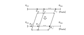
ここで、図9に示すように、位置検出部106により検出される位置自体は、画像平面内における物体51の回転又は移動によって変化する。しかしながら、位置の相対関係(エッジ52間の距離)は変化しない。そこで、図10に示すように、モデル情報記録部101で上記位置の相対関係をテンプレート(位置分布)として記録し、画像から検出された位置をテンプレートと照らし合わせることで、上記位置の相対関係と一致率の高い位置を検索し、その検索した位置に対応する物体モデル51bを抽出する。なお図10において、上段がモデル情報記録部101に記録された位置分布であり、下段が位置検出部106により検出された位置の位置分布(図9Aに対応)である。
Here, as shown in FIG. 9, the position itself detected by the
エッジ52の位置を投影軸54への投影で求めることで、エッジ52の位置分布は回転に依らない特徴量となる。そして、画像平面内における物体51の回転に依らない特徴量を用いることで、探索空間を減らすことができる。また、角度判定部105により角度の相対関係と対応がとれたエッジ52を用いて位置判定を行うので、探索回数を少なくすることができる。
By obtaining the position of the
なお、バラ積み状態等のように物体51の配置される高さ(カメラ50からの距離)が変わる場合には、画像上での物体51の見かけの大きさが変化することになる。そこで、位置判定部107では、モデル情報記録部101で記録した位置の相対関係の倍率を変えながら、マッチングを行うようにしてもよい。
In addition, when the height (distance from the camera 50) at which the
次いで、物体認識部108は、角度判定部105及び位置判定部107により抽出された物体モデル51bの中から、当該角度判定部105及び当該位置判定部107により検索された角度及び位置とモデル情報記録部101に記録された角度及び位置の相対関係の一致率が総合的に高いものを物体51として認識する(ステップST207、物体認識ステップ)。この際、物体認識部108は、例えば、角度の一致率(評価値)と位置の一致率(評価値)との合計が最も高い物体モデル51bを物体51として認識する。
Next, the
次いで、画像内回転角度位置推定部109は、物体認識部108により認識された物体51のエッジ52の角度及びエッジ52の位置から、当該物体51の画像平面内における物体モデル51bに対する回転角度及び位置を推定する(ステップST208、画像内回転角度位置推定ステップ)。この際、画像内回転角度位置推定部109は、物体認識部108により認識された物体51のエッジ52の角度を、モデル情報記録部101に記録された物体モデル51bの対応するエッジ52bの角度と比較し、そのずれ量から当該物体51の画像平面内における物体モデル51bに対する回転角度を推定する。また、モデル情報記録部101に記録された投影点53bの方向を示す情報から、物体認識部108により認識された物体51での、同一の角度のエッジ52毎の投影点53の方向の交点を算出し、その交点から画像平面内での物体51の位置を推定する。
Next, the in-image rotation angle
次いで、三次元位置姿勢推定部110は、画像内回転角度位置推定部109により推定された物体51の回転角度及び位置、及び、物体認識部108により物体51と認識された物体モデル51bに関するモデル情報記録部101に記録された対応する三次元モデル51aの仮想カメラ50bからの距離及び三次元空間における姿勢から、当該物体51の三次元空間における位置及び姿勢を推定する(ステップST209、三次元位置姿勢推定ステップ)。
Next, the three-dimensional position /
この三次元位置姿勢推定ステップでは、三次元位置姿勢推定部110は、まず、モデル情報記録部101に記録された物体モデル51bに対応する三次元モデル51aと仮想カメラ50bとの撮影時の三次元位置関係を参照し、画像内回転角度位置推定部109により推定された物体51の画像平面内における位置から、三次元空間における当該物体51の位置を推定する。
In this three-dimensional position / orientation estimation step, the three-dimensional position /
次いで、物体51の三次元空間における姿勢を推定するために、まず、図11に示すように、モデル情報記録部101に記録された物体モデル51bに対応する三次元モデル51aを撮影した際の三次元空間における姿勢(仮想カメラ50bから見た三次元モデル51aの姿勢)を画像内回転角度位置推定部109により推定された回転角度だけカメラ軸周りに回転(座標変換)することで、物体51が画像内で回転して置かれることを考慮して三次元モデル51aの姿勢を補正する。なお、図11Aは、物体51の見た目の姿勢に合わせるために三次元モデル51aをカメラ軸周りに回転(座標変換)する様子を示す。その様子を投影画像上で示したのが図11Bであり、三次元空間と投影画像との対応関係を示している。
Next, in order to estimate the posture of the
更に、図12に示すように、推定した物体51の三次元空間における位置に対応する姿勢の回転補正(座標変換)を行う。これは、物体51がカメラ50に対して様々な位置に置かれることを考慮して、カメラ50の正面からの位置のずれの分だけ姿勢を補正することを意味する。なお、図12Aは、位置のずれに対応する回転補正(座標変換)の様子を示す。その様子を投影画像上で示したのが図12Bであり、三次元空間と投影画像との対応関係を示している。
Further, as shown in FIG. 12, the rotation correction (coordinate conversion) of the posture corresponding to the estimated position of the
このように、三次元モデル51aを撮影したときの三次元空間における姿勢を出発点にして、カメラ50からの物体51の見た目に合わせるように行った一連の座標変換(カメラ軸周りの回転及び位置ずれの補正)の結果として、物体51の三次元空間における姿勢を推定することができる。
In this way, a series of coordinate transformations (rotation and position around the camera axis) performed so as to match the appearance of the
また、位置判定部107において、モデル情報記録部101で記録した位置の相対関係の倍率を変えてマッチングを行った場合には、三次元位置姿勢推定部110は、その倍率を考慮して物体51のカメラ50からの距離を算出し、物体51の三次元空間における位置及び姿勢を推定する。
When the
以上のように、この実施の形態1によれば、二段階に分けて物体51の認識処理を行う。すなわち、一段階目では、物体モデル51bのエッジ52bの角度の相対関係をテンプレートとして用い、画像から得たエッジ52の角度の中から並びが近い物体モデル51bを候補として抽出する。二段階目では、物体モデル51bのエッジ52bの位置の相対関係をテンプレートとして用い、一段階目で候補として抽出したエッジ52の位置の中から並びが近い物体モデル51bを抽出する。このように、画像平面内で物体51が回転又は移動しても、見た目が同じであれば同一の物体51として認識することで、画像平面内における物体51の回転及び移動に依らない効率的な物体認識を実現することができる。よって、従来構成に対して、簡易な手法で、物体認識の効率化及び高速化を図ることができる。
また、一段階目の角度マッチングにおいて一致率が高いものは位置マッチングへ進むが、一致率が低いものは位置マッチングへは進まないため、従来よりも高速な物体認識が可能となる。
As described above, according to the first embodiment, the
Also, in the first stage of angle matching, if the matching rate is high, the process proceeds to position matching, but if the matching rate is low, the process does not proceed to position matching, so that object recognition can be performed at a higher speed than in the past.
本発明により、画像平面内で物体51が回転又は移動している場合も含めて、高速に解空間の探索が可能になる。また、画像平面内の物体51が物体モデル51bの持つ特徴とどの程度一致しているかを元に物体51の存在可能性を算出するため、バラ積み状態等のように物体51同士が絡んで配置される場合や画像にノイズが含まれる場合等への対応能力が高まる。
According to the present invention, it is possible to search the solution space at high speed including the case where the
実施の形態2.
図13はこの発明の実施の形態2に係る物体認識装置1の構成例を示す図である。この図13に示す実施の形態2に係る物体認識装置1は、図1に示す実施の形態1に係る物体認識装置1に特徴点抽出部111を追加したものである。その他の構成は同様であり、同一の符号を付して異なる部分についてのみ説明を行う。
FIG. 13 is a diagram showing a configuration example of the object recognition apparatus 1 according to
特徴点抽出部111は、画像取得部102により取得された画像から特徴点(円弧、円、楕円等)55の位置を抽出するものである。
また、モデル情報記録部101では、物体モデル51bの特徴点の位置を上記位置の相関関係に含めて記録する。
また、位置判定部107は、位置検出部106により検出された位置及び特徴点抽出部111により抽出された位置の中から、モデル情報記録部101に記録された位置の相対関係との一致率が閾値以上である位置を検索し、当該検索した位置に対応する物体モデル51bを当該モデル情報記録部101から抽出する。
The feature
Further, the model
In addition, the
次に、実施の形態2に係る物体認識装置1の動作例について図14を用いて説明する。図14に示す実施の形態2に係る物体認識装置1の動作例は、図2に示す実施の形態1に係る物体認識装置1の動作例に、ステップST1401を追加し、ステップST206の動作をステップST1402に変更したものである。それ以外のステップは同様であり、その説明を省略する。 Next, an operation example of the object recognition apparatus 1 according to the second embodiment will be described with reference to FIG. The operation example of the object recognition apparatus 1 according to the second embodiment shown in FIG. 14 is obtained by adding step ST1401 to the operation example of the object recognition apparatus 1 according to the first embodiment shown in FIG. This is a change to ST1402. The other steps are the same, and the description thereof is omitted.
なお、モデル情報記録部101(モデル情報記録ステップ)では、事前に、仮想カメラ50bにより投影された物体モデル51bのエッジ52bの角度の相対関係、及び、当該エッジ52bの位置と特徴点の位置の相対関係を示す情報を記録している。この際、エッジ52bの位置と特徴点の位置の相対関係については、上記物体モデル51bが持つ複数のエッジ52bに対して、同一の角度毎に、当該エッジ52b及び特徴点を投影軸(当該角度方向に対する垂線)に投影した位置を求め、それらの位置を位置分布として集めて記録する。
In the model information recording unit 101 (model information recording step), the relative relationship of the angle of the
また、モデル情報記録部101では、物体モデル51bのエッジ52bの角度(基準軸からの絶対角度)、及び、当該物体モデル51bに対応する三次元モデル51aの撮影時の仮想カメラ50bからの距離及び三次元空間における姿勢を示す情報も記録している。更に、モデル情報記録部101では、物体51の三次元モデル51aの三次元空間における任意の点(端、重心、中央の点等)を物体51の三次元空間における位置を表現するための基準点として設定し、画像上の物体モデル51bへの基準点の投影点53bを算出して、同一の角度のエッジ52b毎に、当該エッジ52bから見た基準点の画像上における投影点53bの方向を示す情報も記録している。
なお、モデル情報記録部101は、画像平面内における回転及び移動以外の物体モデル51bの姿勢毎に、上記情報の記録を行う。
In the model
The model
またステップST1401(特徴点抽出ステップ)では、特徴点抽出部111が、画像取得部102により取得された画像から特徴点55の位置を抽出する。この特徴点55の抽出手法は従来手法を用いることができ、その説明を省略する。
In step ST1401 (feature point extraction step), the feature
またステップST1402(位置判定ステップ)では、位置判定部107が、位置検出部106により検出された位置及び特徴点抽出部111により抽出された位置の中から、モデル情報記録部101に記録されたエッジ52bの位置及び特徴点の位置の相対関係との一致率が閾値以上である位置を検索し、当該検索した位置に対応する物体モデル51bを当該モデル情報記録部101から抽出する。この際、図15に示すように、特徴点抽出部111により抽出された特徴点55を、同一の角度のエッジ52毎に投影軸54に投影した位置を求め、マッチングを行う。
In step ST1402 (position determination step), the
ここで、位置検出部106により検出されるエッジ52の位置及び特徴点抽出部111により抽出される特徴点55の位置自体は、画像平面内における物体51の回転又は移動によって変化する。しかしながら、その位置の相対関係(エッジ52及び特徴点55間の距離)は変化しない。そこで、モデル情報記録部101で上記位置の相対関係をテンプレートとして記録し、画像から検出された位置をテンプレートと照らし合わせることで、上記位置の相対関係と一致率の高い位置を検索し、その検索した位置に対応する物体モデル51bを抽出する。
Here, the position of the
以上のように、この実施の形態2によれば、特徴点抽出部111が、画像から特徴点55を抽出し、位置判定部107が、位置検出部106により検出された位置及び特徴点抽出部111により抽出された位置の中から、モデル情報記録部101に記録されたエッジ52bの位置及び特徴点の位置の相対関係との一致率が閾値以上である位置を検索し、当該検索した位置に対応する物体モデル51bを当該モデル情報記録部101から抽出するように構成したので、実施の形態1に対し、認識対象である物体51に特徴点55がある場合には、この特徴点55を鍵として位置マッチングを行うことができ、認識の効率化及び高速化を更に向上することができる。
As described above, according to the second embodiment, the feature
なお、本願発明はその発明の範囲内において、各実施の形態の自由な組み合わせ、あるいは各実施の形態の任意の構成要素の変形、もしくは各実施の形態において任意の構成要素の省略が可能である。 In the present invention, within the scope of the invention, any combination of the embodiments, or any modification of any component in each embodiment, or omission of any component in each embodiment is possible. .
1 物体認識装置
101 モデル情報記録部
102 画像取得部
103 エッジ抽出部
104 角度検出部
105 角度判定部
106 位置検出部
107 位置判定部
108 物体認識部
109 画像内回転角度位置推定部
110 三次元位置姿勢推定部
111 特徴点抽出部
DESCRIPTION OF SYMBOLS 1
Claims (7)
画像取得部が、画像を取得する画像取得ステップと、
エッジ抽出部が、前記画像取得部により取得された画像からエッジを抽出するエッジ抽出ステップと、
角度検出部が、前記エッジ抽出部により抽出されたエッジの角度を検出する角度検出ステップと、
角度判定部が、前記角度検出部により検出された角度の中から、前記モデル情報記録部に記録された角度の相対関係との一致率が閾値以上である角度を検索し、当該検索した角度に対応する物体モデルを当該モデル情報記録部から抽出する角度判定ステップと、
位置検出部が、前記角度判定部により検索された角度に対応するエッジの位置を検出する位置検出ステップと、
位置判定部が、前記位置検出部により検出された位置の中から、前記モデル情報記録部に記録された位置の相対関係との一致率が閾値以上である位置を検索し、当該検索した位置に対応する物体モデルを当該モデル情報記録部から抽出する位置判定ステップと、
物体認識部が、前記角度判定部及び前記位置判定部により抽出された物体モデルの中から、当該角度判定部及び当該位置判定部により検索された角度及び位置と前記モデル情報記録部に記録された角度及び位置の相対関係との一致率が総合的に高いものを物体として認識する物体認識ステップと
を有する物体認識方法。 A model in which the model information recording unit records information indicating the relative relationship between the edge angle and the relative position of the edge of the object model, which is a projection image generated by capturing a three-dimensional model of the object with a virtual camera. An information recording step;
An image acquisition step in which the image acquisition unit acquires an image;
An edge extraction step for extracting an edge from the image acquired by the image acquisition unit;
An angle detection step in which an angle detection unit detects an angle of the edge extracted by the edge extraction unit;
The angle determination unit searches the angle detected by the angle detection unit for an angle whose matching rate with the relative relationship of the angle recorded in the model information recording unit is equal to or greater than a threshold, and sets the searched angle An angle determination step of extracting a corresponding object model from the model information recording unit;
A position detection unit for detecting a position of an edge corresponding to the angle searched by the angle determination unit;
The position determination unit searches the position detected by the position detection unit for a position where the matching rate with the relative relationship of the position recorded in the model information recording unit is equal to or greater than a threshold, A position determination step of extracting a corresponding object model from the model information recording unit;
The object recognition unit is recorded in the model information recording unit and the angle and position retrieved by the angle determination unit and the position determination unit from the object models extracted by the angle determination unit and the position determination unit. An object recognition method comprising: an object recognition step of recognizing an object having a high matching rate with a relative relationship between an angle and a position as an object.
ことを特徴とする請求項1記載の物体認識方法。 The object recognition method according to claim 1, wherein, in the angle detection step, the angle detection unit collects the detected angles having similar values as the same angle.
ことを特徴とする請求項2記載の物体認識方法。 In the position detection step, the position detection unit detects, as the position of the edge, a position obtained by projecting a corresponding edge onto a perpendicular to the angle direction for each identical angle searched by the angle determination unit. The object recognition method according to claim 2, wherein:
画像内回転角度位置推定部が、前記物体認識部により認識された物体のエッジの角度及びエッジの位置から、当該物体の画像平面内における前記物体モデルに対する回転角度及び画像平面内における位置を推定する画像内回転角度位置推定ステップと、
三次元位置姿勢推定部が、前記画像内回転角度位置推定部により推定された物体の回転角度及び位置と、前記物体認識部により物体と認識された物体モデルに関する前記モデル情報記録部に記録された対応する三次元モデルの仮想カメラからの距離及び三次元空間における姿勢から、当該物体の三次元空間における位置及び姿勢を推定する三次元位置姿勢推定ステップとを有する
ことを特徴とする請求項1から請求項3のうちのいずれか1項記載の物体認識方法。 In the model information recording step, the model information recording unit records information indicating a distance from the virtual camera of the three-dimensional model and a posture in the three-dimensional space when the three-dimensional model corresponding to the object model is photographed. ,
The in-image rotation angle position estimation unit estimates the rotation angle of the object relative to the object model in the image plane and the position in the image plane from the edge angle and edge position of the object recognized by the object recognition unit. In-image rotation angle position estimation step;
The three-dimensional position and orientation estimation unit is recorded in the model information recording unit regarding the rotation angle and position of the object estimated by the in-image rotation angle position estimation unit and the object model recognized as the object by the object recognition unit. A three-dimensional position / orientation estimation step for estimating a position and orientation of the object in the three-dimensional space from the distance from the virtual camera of the corresponding three-dimensional model and the attitude in the three-dimensional space. The object recognition method according to claim 3.
前記モデル情報記録ステップにおいて、前記モデル情報記録部は、前記物体モデルの特徴点の位置を前記位置の相関関係に含めて記録し、
前記位置判定ステップにおいて、前記位置判定部は、前記位置検出部により検出された位置及び前記特徴点抽出部により抽出された位置の中から、前記モデル情報記録部に記録された位置の相対関係との一致率が閾値以上である位置を検索し、当該検索した位置に対応する物体モデルを当該モデル情報記録部から抽出する
ことを特徴とする請求項1から請求項4のうちのいずれか1項記載の物体認識方法。 The feature point extraction unit has a feature point extraction step of extracting the position of the feature point from the image acquired by the image acquisition unit;
In the model information recording step, the model information recording unit records the position of the feature point of the object model included in the correlation of the position,
In the position determination step, the position determination unit includes a relative relationship between positions detected by the position detection unit and positions extracted by the feature point extraction unit and recorded in the model information recording unit. 5. The position of which the matching rate is equal to or greater than a threshold is searched, and an object model corresponding to the searched position is extracted from the model information recording unit. 5. The object recognition method described.
ことを特徴とする請求項1から請求項5のうちのいずれか1項記載の物体認識方法。 6. The model information recording step, wherein the model information recording unit records the information for each posture of the object model other than rotation and movement in an image plane. The object recognition method of any one of them.
画像を取得する画像取得部と、
前記画像取得部により取得された画像からエッジを抽出するエッジ抽出部と、
前記エッジ抽出部により抽出されたエッジの角度を検出する角度検出部と、
前記角度検出部により検出された角度の中から、前記モデル情報記録部に記録された角度の相対関係との一致率が閾値以上である角度を検索し、当該検索した角度に対応する物体モデルを当該モデル情報記録部から抽出する角度判定部と、
前記角度判定部により検索された角度に対応するエッジの位置を検出する位置検出部と、
前記位置検出部により検出された位置の中から、前記モデル情報記録部に記録された位置の相対関係との一致率が閾値以上である位置を検索し、当該検索した位置に対応する物体モデルを当該モデル情報記録部から抽出する位置判定部と、
前記角度判定部及び前記位置判定部により抽出された物体モデルの中から、当該角度判定部及び当該位置判定部により検索された角度及び位置と前記モデル情報記録部に記録された角度及び位置の相対関係との一致率が総合的に高いものを物体として認識する物体認識部と
を有する物体認識装置。 A model information recording unit for recording information indicating the relative relationship between the angle of the edge and the relative relationship between the positions of the edge of the object model, which is a projection image generated by capturing a three-dimensional model of the object with a virtual camera;
An image acquisition unit for acquiring images;
An edge extraction unit for extracting an edge from the image acquired by the image acquisition unit;
An angle detection unit for detecting an angle of the edge extracted by the edge extraction unit;
From the angles detected by the angle detection unit, search for an angle whose matching rate with the relative relationship of the angle recorded in the model information recording unit is equal to or greater than a threshold, and an object model corresponding to the searched angle is obtained. An angle determination unit extracted from the model information recording unit;
A position detection unit that detects a position of an edge corresponding to the angle searched by the angle determination unit;
From the positions detected by the position detection unit, a position where the matching rate with the relative relationship of the positions recorded in the model information recording unit is equal to or greater than a threshold is searched, and an object model corresponding to the searched position is obtained. A position determination unit extracted from the model information recording unit;
Of the object models extracted by the angle determination unit and the position determination unit, the angle and the position retrieved by the angle determination unit and the position determination unit and the angle and position recorded in the model information recording unit An object recognition device comprising: an object recognition unit that recognizes an object having a high matching rate with a relationship as an object.
Priority Applications (1)
| Application Number | Priority Date | Filing Date | Title |
|---|---|---|---|
| JP2015220314A JP2017091202A (en) | 2015-11-10 | 2015-11-10 | Object recognition method and object recognition device |
Applications Claiming Priority (1)
| Application Number | Priority Date | Filing Date | Title |
|---|---|---|---|
| JP2015220314A JP2017091202A (en) | 2015-11-10 | 2015-11-10 | Object recognition method and object recognition device |
Publications (1)
| Publication Number | Publication Date |
|---|---|
| JP2017091202A true JP2017091202A (en) | 2017-05-25 |
Family
ID=58769005
Family Applications (1)
| Application Number | Title | Priority Date | Filing Date |
|---|---|---|---|
| JP2015220314A Pending JP2017091202A (en) | 2015-11-10 | 2015-11-10 | Object recognition method and object recognition device |
Country Status (1)
| Country | Link |
|---|---|
| JP (1) | JP2017091202A (en) |
Cited By (3)
| Publication number | Priority date | Publication date | Assignee | Title |
|---|---|---|---|---|
| JP2019211981A (en) * | 2018-06-04 | 2019-12-12 | キヤノン株式会社 | Information processor, information processor controlling method and program |
| WO2020003510A1 (en) | 2018-06-29 | 2020-01-02 | 富士通株式会社 | Identification method, determination method, identification program, determination program, and information processing device |
| WO2021045481A1 (en) * | 2019-09-04 | 2021-03-11 | 삼성전자 주식회사 | Object recognition system and method |
-
2015
- 2015-11-10 JP JP2015220314A patent/JP2017091202A/en active Pending
Cited By (4)
| Publication number | Priority date | Publication date | Assignee | Title |
|---|---|---|---|---|
| JP2019211981A (en) * | 2018-06-04 | 2019-12-12 | キヤノン株式会社 | Information processor, information processor controlling method and program |
| JP7178803B2 (en) | 2018-06-04 | 2022-11-28 | キヤノン株式会社 | Information processing device, information processing device control method and program |
| WO2020003510A1 (en) | 2018-06-29 | 2020-01-02 | 富士通株式会社 | Identification method, determination method, identification program, determination program, and information processing device |
| WO2021045481A1 (en) * | 2019-09-04 | 2021-03-11 | 삼성전자 주식회사 | Object recognition system and method |
Similar Documents
| Publication | Publication Date | Title |
|---|---|---|
| JP5771413B2 (en) | Posture estimation apparatus, posture estimation system, and posture estimation method | |
| US9177404B2 (en) | Systems and methods of merging multiple maps for computer vision based tracking | |
| JP5715833B2 (en) | Posture state estimation apparatus and posture state estimation method | |
| CN109934847B (en) | Method and device for estimating posture of weak texture three-dimensional object | |
| JP6044293B2 (en) | 3D object recognition apparatus and 3D object recognition method | |
| US20140363048A1 (en) | Interactive and automatic 3-d object scanning method for the purpose of database creation | |
| JP4951498B2 (en) | Face image recognition device, face image recognition method, face image recognition program, and recording medium recording the program | |
| JP4709668B2 (en) | 3D object recognition system | |
| WO2016016496A2 (en) | Method for identifying a hand gesture | |
| CN108345821B (en) | Face tracking method and device | |
| EP3624060A1 (en) | Information processing device, information processing method, and program | |
| JP6172432B2 (en) | Subject identification device, subject identification method, and subject identification program | |
| CN110111389B (en) | Mobile augmented reality tracking registration method and system based on SLAM | |
| JP5093591B2 (en) | 3D position and orientation measurement method and apparatus | |
| US9947106B2 (en) | Method and electronic device for object tracking in a light-field capture | |
| JP2014102810A (en) | Subject recognition device, subject recognition method, and subject recognition program | |
| JP2017091202A (en) | Object recognition method and object recognition device | |
| JP2017097578A (en) | Information processing apparatus and method | |
| JP6922348B2 (en) | Information processing equipment, methods, and programs | |
| JP2009129237A (en) | Image processing apparatus and its method | |
| WO2022237048A1 (en) | Pose acquisition method and apparatus, and electronic device, storage medium and program | |
| JP5743935B2 (en) | Object detection apparatus and object detection method | |
| JP6393495B2 (en) | Image processing apparatus and object recognition method | |
| JP2019012497A (en) | Portion recognition method, device, program, and imaging control system | |
| KR101482850B1 (en) | Method and apparatus for hand shape recognition |