JP2017087785A - Steering device - Google Patents
Steering device Download PDFInfo
- Publication number
- JP2017087785A JP2017087785A JP2015216347A JP2015216347A JP2017087785A JP 2017087785 A JP2017087785 A JP 2017087785A JP 2015216347 A JP2015216347 A JP 2015216347A JP 2015216347 A JP2015216347 A JP 2015216347A JP 2017087785 A JP2017087785 A JP 2017087785A
- Authority
- JP
- Japan
- Prior art keywords
- sector
- shaft
- steering
- rack member
- around
- Prior art date
- Legal status (The legal status is an assumption and is not a legal conclusion. Google has not performed a legal analysis and makes no representation as to the accuracy of the status listed.)
- Pending
Links
Images


Abstract
Description
本発明は、車両等の操舵系に於いてステアリングシャフトの回動を螺旋の噛合い機構により直線運動に変換してセクタをセクタシャフトの軸線周りに回動させる操舵装置に係る。 The present invention relates to a steering device that converts a rotation of a steering shaft into a linear motion by a helical meshing mechanism in a steering system of a vehicle or the like and rotates a sector around an axis of a sector shaft.
ステアリングシャフトの回動を螺旋の噛合い機構により直線運動に変換してセクタをセクタシャフトの軸線周りに回動させる操舵装置に於いて、ステアリングシャフトの一部にトーションバーを組込み、操舵に伴ってトーションバーに生ずる捩れにより油圧ポートの開閉を制御してラック部材の直線運動を油圧によりアシストすることに加えて、ステアリングシャフトの回動をセンサにて検出して電動回転子を駆動し、その回転を螺旋の噛合い機構により直線運動に変換してラック部材に電動アシストを付加することが、下記の特許文献1に記載されている。 In a steering device that converts the rotation of the steering shaft into a linear motion by a helical meshing mechanism and rotates the sector around the axis of the sector shaft, a torsion bar is incorporated in a part of the steering shaft, and with steering In addition to controlling the opening and closing of the hydraulic port by torsion generated in the torsion bar and assisting the linear movement of the rack member by hydraulic pressure, the rotation of the steering shaft is detected by a sensor to drive the electric rotor, and the rotation Japanese Patent Application Laid-Open No. H10-228688 describes that the electric power is added to the rack member by converting the motor into a linear motion by a helical meshing mechanism.
本発明は、ステアリングシャフトの回動を螺旋の噛合い機構により直線運動に変換してセクタをセクタシャフトの軸線周りに回動させる操舵装置に於いて、ステアリングシャフトの回動角に対するセクタシャフトの回動角の対応を可変に制御して操舵系のギヤ比を変えることができるようにすると共に、ステアリングシャフトの回動によらずともセクタシャフトを回動させることができるようにすることを課題としている。 The present invention relates to a steering device that converts the rotation of a steering shaft into a linear motion by a helical meshing mechanism to rotate the sector around the axis of the sector shaft. As a problem, it is possible to change the gear ratio of the steering system by variably controlling the correspondence of the moving angle, and to turn the sector shaft without depending on the turning of the steering shaft. Yes.
上記の課題を解決すべく、本発明は、ステアリングシャフトの回動を螺旋の噛合い機構により直線運動に変換してセクタをセクタシャフトの軸線周りに回動させる操舵装置に於いて、前記セクタの歯と噛み合うラック部材は前記螺旋の噛合い機構のナットによりその周りに回動可能に担持され外周に沿って設けられた螺旋歯により前記セクタを前記セクタシャフトの軸線周りに回動させる円筒体であり、前記セクタは前記ラック部材の軸線方向の移動と軸線周りの回動のいずれか一方または両方により前記セクタシャフトを軸線周りに回動させるようになっており、前記ラック部材に所定範囲内の軸線方向移動を許しつつ該ラック部材を軸線周りに回動させる駆動装置が設けられていることを特徴とする操舵装置を提案するものである。 In order to solve the above-described problems, the present invention provides a steering device that converts the rotation of a steering shaft into a linear motion by a helical meshing mechanism to rotate the sector around the axis of the sector shaft. A rack member that meshes with a tooth is a cylindrical body that is rotatably supported around a nut of the spiral meshing mechanism and that rotates the sector around the axis of the sector shaft by a spiral tooth provided along the outer periphery. And the sector rotates the sector shaft around the axis by either or both of movement of the rack member in the axial direction and rotation around the axis, and the rack member is within a predetermined range. The present invention proposes a steering device characterized in that a drive device is provided for rotating the rack member around the axis while allowing movement in the axial direction.
上記の如く、ステアリングシャフトの回動を螺旋の噛合い機構により直線運動に変換してセクタをセクタシャフトの軸線周りに回動させる操舵装置に於いて、前記セクタの歯と噛み合うラック部材は前記螺旋の噛合い機構のナットによりその周りに回動可能に担持され外周に沿って設けられた螺旋歯により前記セクタを前記セクタシャフトの軸線周りに回動させる円筒体であり、前記セクタは前記ラック部材の軸線方向の移動と軸線周りの回動のいずれか一方または両方により前記セクタシャフトを軸線周りに回動させるようになっており、前記ラック部材に所定範囲内の軸線方向移動を許しつつ該ラック部材を軸線周りに回動させる駆動装置が設けられていれば、セクタシャフト軸線周りのセクタの回動は、ステアリングシャフトの回動に伴うラック部材の軸線方向移動とラック部材の軸線周り回動に伴うラック部材の螺旋歯の螺旋の軸線方向移動の複合により定まるので、ステアリングシャフトの回動に合わせて前記駆動装置によりラック部材を回動させることにより、ステアリングシャフトの回動角に対するセクタシャフトの回動角の対応を可変に制御でき、またステアリングシャフトが回動されなくても、前記駆動装置によりラック部材を回動させることによってセクタをセクタシャフト軸線周りに回動させることができ、操舵に自動操舵を取り入れる場合に、自動操舵中には、ステアリングシャフトの回動によらず、前記駆動装置によりラック部材を回動させることにより操舵を行うようにしておけば、自動操舵中にはステアリングホイールは回動せず、また自動操舵中にドライバーが自動操舵を修正したいとき、ドライバーはいつでも停止中のステアリングホイールを修正したい量だけ回動させて、自動操舵に手動修正を加えることができる。 As described above, in the steering device that converts the rotation of the steering shaft into a linear motion by the helical meshing mechanism and rotates the sector around the axis of the sector shaft, the rack member that meshes with the teeth of the sector is the spiral member. A cylindrical body that rotates around the axis of the sector shaft by a helical tooth that is rotatably supported around a nut of a meshing mechanism and that is provided along an outer periphery, and the sector is the rack member The sector shaft is rotated around the axis by one or both of movement in the axial direction and rotation around the axis, and the rack member is allowed to move in the axial direction within a predetermined range. If a drive device that rotates the member around the axis is provided, the rotation of the sector around the axis of the sector shaft is equivalent to the rotation of the steering shaft. This is determined by the combination of the axial movement of the rack member and the axial movement of the helical teeth of the rack member accompanying the rotation of the rack member about the axis, so that the rack is rotated by the drive device in accordance with the rotation of the steering shaft. By moving, the correspondence of the rotation angle of the sector shaft with respect to the rotation angle of the steering shaft can be variably controlled, and even if the steering shaft is not rotated, the rack member is rotated by the drive device to rotate the sector. When the automatic steering is incorporated in the steering, the steering device is rotated by rotating the rack member by the drive device, not by the steering shaft. The steering wheel will not rotate during automatic steering, and during automatic steering. Drivers are times when you want to modify the automatic steering, the driver at any time, is rotated by an amount that you want to modify the steering wheel of stopped, it is possible to make manual modifications to the automatic steering.
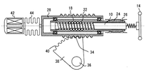
これらの図に於いて、10はステアリングシャフトであり、途中に緩衝部12を含む軸部を経てステアリングホイール14を担持している。ステアリングホイール14によりステアリングシャフト10が回動されると、ステアリングシャフト10に切り込まれたねじ溝16とナット部材18に切り込まれたボール孔20の間にボール22が嵌め込まれた螺旋の噛合い機構によりステアリングシャフト10の回動がナット部材18の直線運動に変換されるようになっている。ナット部材18は、その一端部に設けられたスプライン24が固定スプライン26に係合していることにより、軸線方向には移動できるが、軸線周りには回動しないようになっている。
In these drawings,
ナット部材18の周りには、円筒状のラック部材28がナット部材18により軸受30,32を介して回動可能に担持されている。ラック部材28には、その円筒状の外周に沿って螺旋歯34が設けられており、セクタシャフト36によりその軸線周りに回動するよう担持されたセクタ38がその歯40にてラック部材28の螺旋歯34に噛み合っている。ラック部材28の螺旋歯34の螺旋角は、ラック部材28の回転によりラック部材28の側からセクタ38を駆動することはできるが、セクタ38の側からラック部材28を回転するよう駆動することはできないように設計されてよい。
Around the
図1〜図3に示す実施例に於いては、ラック部材28は電動アクチュエータ42によりダイヤフラム44を介して軸線の周りに回動されるようになっている。尚、ダイヤフラム44は、ラック部材28に所定範囲内の軸線方向移動を許しつつ電動アクチュエータ42とラック部材28の間にトルクを伝達するための手段であり、これに代えて軸線方向の滑りを許容しつつトルクを伝達することができるスプライン継手等他の任意の公知の連結手段が用いられてよい。
In the embodiment shown in FIGS. 1 to 3, the
以上に図示した操舵装置の操舵力を動力手段によりアシストするには、この技術分野に於いて公知の油圧式あるいは電動式ステアリング用パワー手段がセクタシャフト36に作用するように設けられればよい。
In order to assist the steering force of the steering apparatus illustrated above with the power means, it is only necessary to provide a hydraulic or electric steering power means known in this technical field so as to act on the
以上の如く構成された操舵装置に於いて、図1に示す状態から、ラック部材28は回動されず、ステアリングシャフト10が図の右方からみて反時計回り方向に回動されると、図2に示す如く、ラック部材28はダイヤフラム44を圧縮しつつ図にて左方へ移動し、セクタ38は図示の如く左方へ傾動し、セクタシャフト36が図にて反時計回り方向に回動される。
In the steering apparatus configured as described above, when the
一方、上記の構成に於いて、ラック部材28の螺旋歯34が今仮にステアリングシャフト10のねじ溝16と同じ右ねじの螺旋歯であるとして、図1に示す状態から、ステアリングシャフト10は回動されず、ラック部材28が電動アクチュエータ42により図の右方からみて反時計回り方向に回動されると、図3に示す如く、ラック部材28は、軸線方向に移動することなく、軸線周りに回動し、螺旋歯34の螺旋が図にて左方へ移動し、セクタ38は図示の如く左方へ傾動し、セクタシャフト36が図にて反時計回り方向に回動される。
On the other hand, in the above configuration, assuming that the
セクタシャフト36の軸線周りの回動は、図2に示す如きステアリングシャフト10の回動に伴うラック部材28の軸線方向移動と、図3に示す如きラック部材28の軸線周り回動に伴うラック部材28の螺旋歯34の螺旋の軸線方向移動の複合により定まる。従って、ステアリングシャフト10の回動に合わせて電動アクチュエータ42によりラック部材28を回動させることにより、ステアリングシャフト10の回動角に対するセクタシャフト36の回動角の対応を可変に制御し、操舵系のギヤ比を可変に制御することができる。またステアリングシャフト10が回動されなくても、電動アクチュエータ42によりラック部材28を回動させることによって、セクタ38をセクタシャフト36の軸線周りに回動させることができるので、操舵に自動操舵を取り入れる場合に、自動操舵中には、電動アクチュエータ42によりラック部材28を回動させることにより操舵を行うようにしておけば、自動操舵中には、ステアリングホイール14は回動せず、また自動操舵中にドライバーが自動操舵を修正したいときには、ドライバーはいつでも停止中のステアリングホイール14を修正したい量だけ回動させて、自動操舵に手動修正を加えることができる。
The rotation of the
図1〜図3に示す構成において、ステアリングシャフト10のねじ溝16の螺旋角が小さければ、ステアリングシャフト10の回転によってナット部材18を軸線方向に駆動することはできるが、ナット部材18の側からその軸線方向移動によりステアリングシャフト10を回転させるように駆動することはできない逆止作用が得られ、車輪が路面より受ける偏向力によりセクタシャフトに車輪側から作用したトルクがセクタ38とラック部材28の噛合い部を経てナット部材18を軸線方向に駆動しても、それによってステアリングシャフト10に回転トルクが生じにくいが、ねじ溝16の螺旋角の大きさ次第では、ステアリングシャフト10に回転トルクが生じ、それがステアリングホイールに衝撃的に伝わる虞れがある。
In the configuration shown in FIGS. 1 to 3, if the helical angle of the
図4は、図1〜図3に示す実施例にそのようなセクタ側からステアリングシャフトへ向かう力の衝撃的逆伝達を抑制するダンピング装置を追加した構成を示す。図示の如く、電動アクチュエータ42よりダイヤフラム44を経てラック部材28を回転駆動する軸46の途中に、シリンダ室48内にてピストン50が作動流体の抵抗を受けつつ移動するダンピング装置52が設けられている。シリンダ室48内に於けるピストン50の移動につれてピストン50の両側の作動室の間に流れる作動流体の流れが絞り弁54により絞られることにより、ラック部材28に軸線方向に作用する衝撃力に対し緩衝作用が与えられる。絞り弁54の絞り度をソレノイド56により制御することにより、ラック部材28に作用する衝撃力に対しそれを抑制する緩衝作用を最適化することができる。
FIG. 4 shows a configuration in which a damping device that suppresses the impact reverse transmission of the force from the sector side toward the steering shaft is added to the embodiment shown in FIGS. As shown in the figure, a
以上に於いては本発明を一つの実施例とその一部の修正例について詳細に説明したが、かかる実施例について本発明の範囲内にて種々の変更が可能であることは当業者にとって明らかであろう。 Although the present invention has been described in detail with respect to one embodiment and some modifications thereof, it will be apparent to those skilled in the art that various modifications can be made within the scope of the present invention. Will.
10…ステアリングシャフト、12…緩衝部、14…ステアリングホイール、16…ねじ溝、18…ナット部材、20…ボール孔、22…ボール、24…スプライン、26…固定スプライン、28…ラック部材、30,32…軸受、34…螺旋歯、36…セクタシャフト、38…セクタ、40…歯、42…電動アクチュエータ、44…ダイヤフラム、46…軸、48…シリンダ室、50…ピストン、52…ダンピング装置、54…絞り弁、56…ソレノイド
DESCRIPTION OF
Claims (1)
Priority Applications (1)
| Application Number | Priority Date | Filing Date | Title |
|---|---|---|---|
| JP2015216347A JP2017087785A (en) | 2015-11-04 | 2015-11-04 | Steering device |
Applications Claiming Priority (1)
| Application Number | Priority Date | Filing Date | Title |
|---|---|---|---|
| JP2015216347A JP2017087785A (en) | 2015-11-04 | 2015-11-04 | Steering device |
Publications (1)
| Publication Number | Publication Date |
|---|---|
| JP2017087785A true JP2017087785A (en) | 2017-05-25 |
Family
ID=58770109
Family Applications (1)
| Application Number | Title | Priority Date | Filing Date |
|---|---|---|---|
| JP2015216347A Pending JP2017087785A (en) | 2015-11-04 | 2015-11-04 | Steering device |
Country Status (1)
| Country | Link |
|---|---|
| JP (1) | JP2017087785A (en) |
Cited By (2)
| Publication number | Priority date | Publication date | Assignee | Title |
|---|---|---|---|---|
| CN112937675A (en) * | 2021-04-06 | 2021-06-11 | 舍弗勒技术股份两合公司 | Electric power steering apparatus |
| CN114206666A (en) * | 2019-06-04 | 2022-03-18 | 亿迈齿轮两合股份公司 | Linear drive, longitudinal seat adjustment unit and motor vehicle |
-
2015
- 2015-11-04 JP JP2015216347A patent/JP2017087785A/en active Pending
Cited By (4)
| Publication number | Priority date | Publication date | Assignee | Title |
|---|---|---|---|---|
| CN114206666A (en) * | 2019-06-04 | 2022-03-18 | 亿迈齿轮两合股份公司 | Linear drive, longitudinal seat adjustment unit and motor vehicle |
| CN114206666B (en) * | 2019-06-04 | 2023-09-22 | 亿迈齿轮两合股份公司 | Linear drive, longitudinal adjustment unit for a seat, and motor vehicle |
| US11865951B2 (en) | 2019-06-04 | 2024-01-09 | Ims Gear Se & Co. Kgaa | Linear drive, longitudinal-adjustment unit for a seat, and motor vehicle |
| CN112937675A (en) * | 2021-04-06 | 2021-06-11 | 舍弗勒技术股份两合公司 | Electric power steering apparatus |
Similar Documents
| Publication | Publication Date | Title |
|---|---|---|
| US9022167B2 (en) | Hybrid power steering system | |
| US9004219B2 (en) | Drive control system | |
| WO2020115920A1 (en) | Reactive force generation device and steering device | |
| JP2017165327A (en) | Steering device | |
| JP2012530209A (en) | Valve with motion conversion device | |
| JP2016150645A (en) | Power steering device | |
| JPH06344934A (en) | Power steering device | |
| CN111806549A (en) | Steering column assembly for vehicle | |
| JP2017087785A (en) | Steering device | |
| JP2007161082A (en) | Electric power steering device | |
| JP7112344B2 (en) | steering device | |
| JP2010184599A (en) | Electric power steering device | |
| EP1669274A1 (en) | Speed reduction gear of electric power steering device | |
| JP2017081451A (en) | Steering device | |
| JP2016030521A (en) | Vehicular steering device | |
| US20080257087A1 (en) | Position Feedback Device for an Actuator | |
| JP4433183B2 (en) | Power steering device | |
| EP3089906B1 (en) | Hydraulically assisted steering system for motor vehicles | |
| JP5367238B2 (en) | Ball screw actuator and steering apparatus using the same | |
| JP2006137256A (en) | Steering device | |
| JP6360446B2 (en) | Rack shaft pressing mechanism | |
| JP2016120729A (en) | Electric assist device and its manufacturing method | |
| JP3074339B2 (en) | Steering and reduction gears | |
| KR20150034051A (en) | Motor driven power steering apparatus | |
| JP4352325B2 (en) | Electric power steering device |