JP2017083702A - Image forming apparatus and management system - Google Patents
Image forming apparatus and management system Download PDFInfo
- Publication number
- JP2017083702A JP2017083702A JP2015213021A JP2015213021A JP2017083702A JP 2017083702 A JP2017083702 A JP 2017083702A JP 2015213021 A JP2015213021 A JP 2015213021A JP 2015213021 A JP2015213021 A JP 2015213021A JP 2017083702 A JP2017083702 A JP 2017083702A
- Authority
- JP
- Japan
- Prior art keywords
- image forming
- recording material
- amount
- forming apparatus
- stiffness
- Prior art date
- Legal status (The legal status is an assumption and is not a legal conclusion. Google has not performed a legal analysis and makes no representation as to the accuracy of the status listed.)
- Pending
Links
Images


Abstract
Description
本発明は、電子写真方式を利用した複写機、プリンタ、ファクシミリ装置等の画像形成装置と、その管理システムに関する。 The present invention relates to an image forming apparatus such as a copying machine, a printer, and a facsimile apparatus using an electrophotographic system, and a management system thereof.
従来、電子写真方式の画像形成装置は、複写機、プリンタ、ファクシミリ等に適用されている。これらの画像形成装置では、ユーザが設定した記録材の種別情報を利用したり、画像形成装置に厚みセンサを設けたり(例えば、特許文献1参照)、画像形成装置内で剛度検知を行ったり(例えば、特許文献2参照)等して、記録材の特性を取得している。取得された記録材の特性は、画像形成条件の決定に用いられ、様々な記録材に対して所定の品質の画像を形成することができる。 Conventionally, an electrophotographic image forming apparatus is applied to a copying machine, a printer, a facsimile, and the like. In these image forming apparatuses, recording material type information set by the user is used, a thickness sensor is provided in the image forming apparatus (see, for example, Patent Document 1), or stiffness detection is performed in the image forming apparatus ( For example, the characteristics of the recording material are acquired as described in Patent Document 2). The acquired characteristics of the recording material are used to determine the image forming conditions, and images of a predetermined quality can be formed on various recording materials.
また、電子写真方式の画像形成装置には、トナー補給容器等の消耗品、又は感光ドラム、現像装置、定着装置、転写装置等の部材が装着されている。これらの部材の中で、画像形成装置本体について保証された動作時間(以下、寿命という)に比べ寿命が短い部材は、それぞれがユニット化されている。これらのユニットが寿命に達すると、ユニット単位で新品のユニットに交換される。これにより、画像形成装置の継続的な使用に対応している。ところが近年では、このような画像形成装置の管理コストを削減したいというニーズが強まっている。上述したユニットに対しても、ユニットの寿命を精度よく検知又は予測して報知し、ユニットを寿命に達するまで長く使用することで、ユニットの交換の頻度を低下させ、管理コストを低減させることが望まれている。 The electrophotographic image forming apparatus is equipped with consumables such as a toner supply container, or members such as a photosensitive drum, a developing device, a fixing device, and a transfer device. Among these members, the members whose lifetime is shorter than the operation time guaranteed for the image forming apparatus main body (hereinafter referred to as the lifetime) are unitized. When these units reach the end of their lives, they are replaced with new units. Thereby, it corresponds to the continuous use of the image forming apparatus. However, in recent years, there is an increasing need to reduce the management cost of such an image forming apparatus. Even for the units described above, the unit life can be accurately detected or predicted, and the unit can be used for a long time until it reaches the end of its life, thereby reducing the frequency of unit replacement and reducing the management cost. It is desired.
交換可能なユニットの寿命の報知を正確に行うためには、それぞれのユニットの性能の低下の度合い(以下、劣化度合いという)を精度よく見積もる必要がある。このようなユニットについて、記録材の搬送に関わる回転搬送手段の劣化度合いを精度よく見積もる方法としては、記録材が搬送された枚数や回転搬送手段の回転数をモニターする方法が一般的で容易である。この方法では、搬送された記録材が所定の枚数又は回転搬送手段が所定の回転数を超えたタイミングで、ユニットの寿命の予告や寿命に到達したこと等のメッセージが、画像形成装置本体や接続されているパーソナルコンピュータ(以下、PC)側に示される。ユニットの劣化度合いを精度よく見積もる手法として、次のような手法がある。例えば、画像形成装置が有するモードの違い(例えば、普通紙とOHTを区別する)や、連続して搬送される記録材の枚数の違いに応じて、演算結果に重み付け係数を乗算する方法が提案されている(例えば、特許文献3参照)。また、画像形成装置により検知された記録材の平滑度やユーザにより入力された記録材の坪量に応じて、劣化度合いの見積もり精度を向上させる手法が提案されている(例えば、特許文献4参照)。 In order to accurately report the life of a replaceable unit, it is necessary to accurately estimate the degree of deterioration of the performance of each unit (hereinafter referred to as the degree of deterioration). For such a unit, as a method for accurately estimating the degree of deterioration of the rotary conveying means related to the conveyance of the recording material, a method for monitoring the number of recording materials conveyed and the number of rotations of the rotary conveying means is generally easy. is there. In this method, when the number of conveyed recording materials or the rotation conveying means exceeds the predetermined number of rotations, a message such as a notice of the unit life or the fact that the life has been reached is displayed on the image forming apparatus main body or connection. It is shown on the personal computer (hereinafter, PC) side. As a method for accurately estimating the degree of deterioration of the unit, there is the following method. For example, a method is proposed in which the calculation result is multiplied by a weighting coefficient according to a difference in modes of the image forming apparatus (for example, distinguishing between plain paper and OHT) or a difference in the number of sheets of recording material that are continuously conveyed. (For example, see Patent Document 3). In addition, a method has been proposed for improving the estimation accuracy of the degree of deterioration according to the smoothness of the recording material detected by the image forming apparatus and the basis weight of the recording material input by the user (see, for example, Patent Document 4). ).
ユーザが使用する記録材に応じてユニットの劣化度合いを見積もる際に、記録材の平滑度や坪量を考慮することで、ある程度の見積もり精度の向上は図れる。しかし、本発明者らの検討によれば、同程度の平滑度と坪量の記録材を用いて同じような条件で画像形成装置を動作させているにも関わらず、回転搬送手段の劣化度合いに違いが生じる場合があることが判明した。 When estimating the degree of deterioration of the unit according to the recording material used by the user, the estimation accuracy can be improved to some extent by considering the smoothness and basis weight of the recording material. However, according to the study by the present inventors, the degree of deterioration of the rotary conveying means is achieved despite the fact that the image forming apparatus is operated under the same conditions using recording materials having the same level of smoothness and basis weight. It has been found that there may be differences.
本発明は、このような状況のもとでなされたもので、搬送される記録材に応じて搬送手段の性能の低下の度合いを精度よく見積もることを目的とする。 The present invention has been made under such circumstances, and an object of the present invention is to accurately estimate the degree of deterioration in the performance of the conveying means in accordance with the recording material to be conveyed.
上述した課題を解決するために、本発明は、以下の構成を備える。 In order to solve the above-described problems, the present invention has the following configuration.
(1)記録材を搬送する搬送手段と、前記搬送手段の劣化度合いを演算する演算手段と、を備え、前記演算手段は、前記劣化度合いを演算する際に、記録材の剛度に応じた補正を行うことを特徴とする画像形成装置。 (1) A conveyance unit that conveys the recording material and a calculation unit that calculates the degree of deterioration of the conveyance unit, and the calculation unit corrects according to the stiffness of the recording material when calculating the degree of deterioration. An image forming apparatus.
(2)複数の画像形成装置と、前記複数の画像形成装置とネットワーク回線を介して接続された管理装置と、を備える管理システムであって、前記画像形成装置は、記録材を載置する複数の載置部と、記録材を搬送する搬送手段と、前記搬送手段の劣化度合いを演算する演算手段と、を有し、前記管理装置は、前記複数の画像形成装置の前記複数の載置部の各々に載置された記録材についての剛度を、前記複数の載置部の各々に対して一括して設定することが可能な設定手段を有し、前記演算手段は、前記設定手段により設定された前記剛度に基づいて前記劣化度合いを演算し、演算した前記劣化度合いに基づいて前記搬送手段の寿命演算を行うことを特徴とする管理システム。 (2) A management system including a plurality of image forming apparatuses and a management apparatus connected to the plurality of image forming apparatuses via a network line, wherein the image forming apparatus is a plurality of recording materials. And a calculating unit that calculates a degree of deterioration of the conveying unit, and the management device includes the plurality of mounting units of the plurality of image forming apparatuses. A setting unit capable of collectively setting the stiffness of the recording material placed on each of the plurality of placement units, and the calculation unit is set by the setting unit. A management system, wherein the deterioration degree is calculated based on the rigidity, and the life of the conveying means is calculated based on the calculated deterioration degree.
本発明によれば、搬送される記録材に応じて搬送手段の性能の低下の度合いを精度よく見積もることができる。 According to the present invention, it is possible to accurately estimate the degree of deterioration of the performance of the conveying means according to the recording material to be conveyed.
以下、本発明を実施するための形態を、実施例により図面を参照しながら詳しく説明する。なお、画像形成装置本体や各ユニットについて保証された動作時間を、以下、寿命といい、各ユニットの性能の低下の度合いを、以下、劣化度合いという。 DESCRIPTION OF EMBODIMENTS Hereinafter, embodiments for carrying out the present invention will be described in detail by way of examples with reference to the drawings. The operation time guaranteed for the image forming apparatus main body and each unit is hereinafter referred to as a lifetime, and the degree of deterioration of the performance of each unit is hereinafter referred to as a deterioration degree.
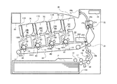
実施例1では、搬送路中に設けられた剛度検知手段によって検知された記録材の剛度に応じて、画像形成装置を構成する回転搬送手段の寿命の演算を行う。ここで、記録材の剛度は、紙の折りや曲げに対する抵抗性を示す度合いであり、紙のこしとも、紙のこわさともいわれる。図1は、本実施例の画像形成装置の概略断面図である。本実施例では、画像形成装置の一例として中間転写ベルトを採用したカラー画像形成装置を用いるが、他の構成の画像形成装置であってもよい。 In the first exemplary embodiment, the life of the rotary conveyance unit constituting the image forming apparatus is calculated according to the stiffness of the recording material detected by the stiffness detection unit provided in the conveyance path. Here, the stiffness of the recording material is a degree indicating resistance to folding and bending of the paper, and is also referred to as paper stiffness or paper stiffness. FIG. 1 is a schematic cross-sectional view of the image forming apparatus of this embodiment. In this embodiment, a color image forming apparatus employing an intermediate transfer belt is used as an example of the image forming apparatus, but an image forming apparatus having another configuration may be used.
[画像形成装置]
本実施例の画像形成装置は、4ドラムフルカラー方式のプリンタである。画像形成部は、イエロー(Y)、マゼンタ(M)、シアン(C)、ブラック(K)の各色ステーションに設けられた像担持体としての感光ドラム1Y、1M、1C、1Kを備えている。なお、色を表すY、M、C、Kは、必要な場合を除き、以降省略する。また、画像形成部は、帯電手段としての帯電ローラ2、スキャナ部11、現像手段としての現像器8、トナー補給手段としてのトナー容器7、ドラムクリーナ16、回転体である中間転写ベルト24、二次転写ローラ25を備えている。また、画像形成部は、中間転写ベルト24を駆動しつつ、二次転写ローラ25の対向ローラとして機能する駆動ローラ26、張架ローラ13、補助ローラ23、一次転写ローラ4、定着手段としての定着部21を備えている。さらに、画像形成部は、これらを制御して動作させる、演算手段である制御演算部10を備えている。感光ドラム1は、アルミシリンダの外周に有機光導伝層を塗布して構成され、不図示の駆動モータの駆動力が伝達されて回転する。駆動モータは、感光ドラム1を画像形成動作に応じて図中矢印方向(時計回り方向)に回転させる。
[Image forming apparatus]
The image forming apparatus of this embodiment is a four-drum full color printer. The image forming unit includes
制御演算部10が画像信号を受信すると、記録材Pは、記録材Pが載置された載置部である給紙カセット15Aからピックアップローラ14、給紙ローラ17、18によって画像形成装置内に送り出される。記録材Pは、後述する画像形成動作と記録材Pの搬送との同期をとるためのローラ状同期回転体、即ち、レジストレーションローラ対19a、19bに一旦挟持され、停止して待機する。
When the control
一方、制御演算部10は、帯電ローラ2により一定電位に帯電された感光ドラム1の表面に、受信した画像信号に応じた静電潜像をスキャナ部11によって形成する。現像器8は静電潜像を可視化する手段であり、ステーション毎にYMCK各色の現像を行う。現像器8には、現像ローラ5が設けられており、静電潜像を可視化するための現像電圧が印加されている。このように、感光ドラム1の表面に形成された静電潜像は、現像器8により単色のトナー像として現像される。
On the other hand, the
中間転写ベルト24は、感光ドラム1に接触しており、カラー画像形成時に、図中矢印方向(反時計回り方向)に感光ドラム1の回転と同期して回転する。現像された単色のトナー像は、一次転写ローラ4に印加された一次転写電圧により順次、重畳して転写され、中間転写ベルト24上で多色のトナー像となる。ここで、中間転写ベルト24上に転写されずに感光ドラム1上に残留したトナーは、感光ドラム1に当接して設置されたドラムクリーナ16により回収される。ドラムクリーナ16は、クリーナブレード161とトナー回収容器162を有している。
The
中間転写ベルト24上に形成された多色のトナー像は、中間転写ベルト24と二次転写ローラ25とで形成される二次転写ニップ部に搬送される。中間転写ベルト24上のトナー像が二次転写ニップ部に搬送されるタイミングに合わせて、レジストレーションローラ対19a、19bに挟持された状態で待機していた記録材Pの搬送が再開される。記録材Pは、レジストレーションローラ対19a、19bにより中間転写ベルト24上の多色のトナー像の搬送と同期を取りながら二次転写ニップ部に搬送される。二次転写ニップ部に搬送された記録材Pには、二次転写ローラ25に印加された二次転写電圧により多色のトナー像が一括転写される。定着部21は大別して、弾性層を有し回転する加圧ローラ21aと、加圧ローラ21aに圧接し定着ニップ部Nを形成し、定着ニップ部Nを加熱する加熱手段であるヒータ等を有した加熱回転体21bから構成される。
The multicolor toner image formed on the
[定着部]
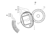
図2に定着部21の概略構成図を示す。加熱回転体21bを構成する耐熱性を有する円筒状の加熱フィルム211は、加熱フィルム211を円筒状に保持する支持ホルダー212と、支持ホルダー212を保持する金属製の定着ステー213の外周に緩やかに嵌合されている。支持ホルダー212の長手方向には、板状発熱体214が保持され、不図示の加圧手段により、板状発熱体214は、加熱フィルム211を介して加圧ローラ21aと加圧力Fで定着ニップ部Nを形成している。加圧ローラ21aと板状発熱体214に挟持された加熱フィルム211は、加圧ローラ21aに対して支持ホルダー212及び定着ステー213の周りを従動回転する。加熱フィルム211の内面には温度検知手段であるセンサ215が当接され、加熱フィルム211の内面温度が検知され、検知された温度に基づいて制御演算部10により、加熱フィルム211の温度が所定の値となるように制御される。本実施例の加熱フィルム211は、厚さ35μmのステンレス材を基層としたフィルム211Bを有している。このフィルム211Bに、熱伝導性を付与したシリコーンゴムからなる厚さ300μmの弾性層211R、及びPFA材料からなる厚さ25μmの離型性層211Sを順次形成している。
[Fixing part]
FIG. 2 shows a schematic configuration diagram of the fixing
多色のトナー像を保持した記録材Pは、加圧ローラ21aにより搬送されるとともに、定着ニップ部Nにて熱及び圧力を加えられ、トナーが表面に定着される。図1に戻り、トナー像の定着後の記録材Pは、排出ローラ20a、20bによって排紙トレイ30に排出され画像形成動作を終了する。
The recording material P holding the multicolor toner image is conveyed by the
ベルトクリーナ28は、記録材Pへの転写後に中間転写ベルト24上に残ったトナーをクリーナブレード281によってクリーニングするものであり、ここで回収されたトナーはクリーナ容器282に蓄えられる。
The
以上説明したような一連の画像形成動作は、制御演算部10によって制御動作される。制御演算部10は、コントロールパネル35や不図示のホストコンピュータに接続されており、それらから入力されたコマンドに応じて画像形成装置を制御する。また、制御演算部10は、画像形成装置や各ユニットの状態をアラート音及びメッセージ表示でユーザに伝える通知手段として、また、後述する画像形成装置の回転搬送手段の寿命を演算する演算手段としても機能する。さらに、制御演算部10は、回転搬送手段の寿命を演算する演算に必要な各種パラメータを記憶する記憶手段としても機能する。
A series of image forming operations as described above are controlled by the
[寿命の演算方法]
本実施例では、定着部21の劣化度合いを予測演算し、演算して得られた値に基づき、定着部21の寿命演算を行う方法について説明する。具体的には、劣化度合いの予測演算により得られる値として、回転手段である加熱フィルム211における離型性層211Sの摩耗量を演算し、離型性層211Sの摩耗量を記録材Pの剛度に応じて補正する。本実施例に使用した画像形成装置は、制御演算部10において、記録材Pの搬送による離型性層211Sの摩耗量の標準値を、1ページあたり0.84×10⁻⁴μmとし、1枚の記録材Pを搬送する毎に摩耗量を積算して保持している。
[Life calculation method]
In the present embodiment, a method for predicting and calculating the degree of deterioration of the fixing
また、画像形成装置が実際に使用される環境においては、単位ページあたりの摩耗量よりも、加熱フィルム211の単位回転数あたりの摩耗量を基準にする方が、予測演算の精度が向上する場合もある。そこで、本実施例では、実測した加熱フィルム211の回転数も計測しておき、1回転あたりの摩耗量の標準値を0.17×10⁻⁵μmとして摩耗量を演算し、積算して保持することとする。そして、積算された摩耗量が、予め定められた定着部21の寿命値にどれだけ近づいたかを百分率で示す寿命演算を行う。前述した通り、本実施例に用いた離型性層211Sの厚みの初期値は25μmである。しかし、離型性層211Sの摩耗が進行して厚みが極端に薄くなると、離型性層211Sに微小な亀裂が発生し、離型性能の効果が充分に発揮されず、画像の品質が低下してしまうおそれがある。したがって、本実施例では、離型性層211Sの積算された摩耗量の寿命値を23μmとし、以下の式(1)によって寿命演算を行う。
In an environment where the image forming apparatus is actually used, the accuracy of the prediction calculation is improved by using the wear amount per unit rotation number of the
式(1)では、定着部21の残りの寿命(以下、残寿命という)を求める。ここで、寿命値とは、離型性層211Sの摩耗量の積算値をいい、本実施例では、離型性層211Sの摩耗量の積算値が23μmとなったとき、定着部21が寿命に達したものとする。言い換えれば、離型性層211Sの厚みが2μm(=25μm−23μm)となったときを、定着部21の寿命とする。離型性層211Sの摩耗量の積算値が23μmとなったとき、定着部21を交換するタイミングとなる。
残寿命(%)=(1−(積算摩耗量(μm)/23))×100 式(1)
式(1)の残寿命(%)の演算結果は、コントロールパネル35に表示され、ユーザに通知される。
In Expression (1), the remaining life of the fixing unit 21 (hereinafter referred to as the remaining life) is obtained. Here, the life value refers to an integrated value of the wear amount of the
Remaining life (%) = (1− (cumulative wear amount (μm) / 23)) × 100 Formula (1)
The calculation result of the remaining life (%) of Expression (1) is displayed on the
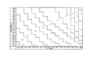
ところで、離型性層211Sの摩耗量は、搬送される記録材の種類によって差が生じることが知られている。一般的には、記録材の表面平滑度が高いほど、また、坪量が小さいほど、摩耗量は少ないと考えられている。しかし、本発明者らの検討によれば、同じような平滑度や坪量を有する異なる種類の記録材に対し、同じような条件で画像形成を行ったにもかかわらず、離型性層211Sの摩耗量に違いが生じる場合があることが確認された。図3(a)は、平滑度の異なる複数の記録材を用いて画像形成装置による画像形成動作の試験を行った際に計測した離型性層211Sの摩耗量を、単位ページあたりの摩耗量に換算した結果である。図3(a)の横軸は、ベック式測定法により測定した平滑度(ベック平滑度)(sec)であり、縦軸は離型性層211Sの単位ページあたりの摩耗量(×10−4μm/Page)である。なお、平滑度とは、記録材の紙面の滑らかさの度合いをいい、所定量の空気が紙面の凹凸の間隙を通り抜ける時間(秒)で表し、数値が大きいほど記録材が滑らかであることを示す。
By the way, it is known that the wear amount of the
同様に、図3(b)は、同じ試験の結果を記録材の坪量に対してプロットした結果である。図3(b)の横軸は、坪量(g/m2)であり、縦軸は離型性層211Sの単位ページあたりの摩耗量(×10−4μm/Page)である。いずれの結果も、大まかな傾向としては、一般的な考え方に沿った結果であるといえる。即ち、図3(a)では、紙面の凹凸が少ない(即ち、平滑度の高い)記録材ほど、離型性層211Sの摩耗量が小さい。また、図3(b)では、坪量が小さい記録材ほど、離型性層211Sの摩耗量が小さい。しかし、図3(a)の相関係数R2は0.15程度、図3(b)の相関係数R2は0.50程度であり、離型性層211Sの摩耗量の予測演算の精度の向上には、更なる改善の余地があるといえる。
Similarly, FIG. 3B is a result of plotting the result of the same test against the basis weight of the recording material. The horizontal axis of FIG.3 (b) is basic weight (g / m < 2 >), and a vertical axis | shaft is the abrasion loss (* 10 < -4 > micrometer / Page) per unit page of the
このような結果に対して更なる検討を行ったところ、記録材の剛度と離型性層211Sの摩耗量とは強い相関関係にあり、その相関係数R2は0.73となることが判明した。図3(c)、図3(d)にその結果を示す。この検討における記録材の剛度の測定方法としては、JIS P8143記載のクラークこわさ試験機法を採用している。ここで、クラーク剛度と相関性のある他の手法として、例えばJAPAN TAPPI No.40のガーレ法やJIS P8125のテーバーこわさ試験機法、又はTAPPI UM409の簡便法等がある。これらのクラーク剛度と相関性のある他の手法を用いて測定しても、離型性層211Sの摩耗量と同様の相関関係が得られると考えられる。
Was subjected to further consideration for such a result lies in the strong correlation between rigidity and the release layer wear amount of 211S of the recording material, the correlation coefficient R 2 is be a 0.73 found. The results are shown in FIGS. 3 (c) and 3 (d). As a method for measuring the stiffness of the recording material in this study, the Clark stiffness tester method described in JIS P8143 is adopted. Here, as another technique correlated with Clark stiffness, for example, JAPAN TAPPI No. 40 Gurley method, JIS P8125 Taber stiffness tester method, or TAPPI UM409 simple method. It is considered that the same correlation as the wear amount of the
図3(c)、図3(d)の横軸は、クラークこわさ試験機法により測定した記録材の剛度(クラーク剛度)(cm3/100)である。図3(c)の縦軸は、離型性層211Sの単位ページあたりの摩耗量(×10−4μm/Page)、図3(d)の縦軸は、離型性層211Sの単位回転数あたりの摩耗量(×10−6μm/回転)である。いずれも、記録材の剛度が低いほど、離型性層211Sの摩耗量が小さい。
FIG. 3 (c), the horizontal axis of FIG. 3 (d), a stiffness of the recording material measured by Clark stiffness tester method (Clark stiffness) (cm 3/100). The vertical axis of FIG. 3C is the wear amount per unit page of the
以上のような検討結果を踏まえ、本実施例では、図1に示すように、給紙ローラ17と給紙ローラ18の間に、剛度を検出する検出手段として、記録材Pの自重たわみ量を測定するための測距センサ40を配置している。そして、測距センサ40の検知結果に基づき求められた記録材Pの自重たわみ量に基づいて、TAPPI UM409測定法の原理を用いて記録材の剛度を求める。そして、求めた記録材の剛度に応じて、前述した離型性層211Sの摩耗量の標準値に対して補正演算を行う構成としている。
Based on the above examination results, in this embodiment, as shown in FIG. 1, the self-weight deflection amount of the recording material P is detected between the
図4は、測距センサ40の近傍の要部を示す図である。図4に示すように、記録材Pが給紙カセット15Aから給紙され、記録材Pの先端が給紙ローラ17のニップ部を通過すると、給紙ローラ17のニップ部よりも記録材Pの先端が自重により下方にたわむ。既知の値である測距センサ40から一点鎖線で示す給紙ローラ17のニップ部の高さまでの距離と、測距センサ40から二点鎖線で示す記録材Pまでの距離との差を、自重たわみ量Sとする。制御演算部10は、測距センサ40により検知された距離に基づき求めた自重たわみ量Sに応じて、予め実験等で得られた0.5から1.6の補正係数P(S)を決定する。
FIG. 4 is a diagram illustrating a main part in the vicinity of the
具体的には、制御演算部10は、図4に示す自重たわみ量Sに応じて0.5から1.6の補正係数P(S)を決定する。そして、制御演算部10は、決定された補正係数P(S)を、記録材Pの1ページあたりの離型性層211Sの摩耗量の標準値(0.84×10⁻⁴μm)に乗算したうえで、ページ毎に積算する。このようにして積算された摩耗量(積算摩耗量(μm))は、以下の式(2)で表される。なお、式(2)の積算摩耗量はページ数での積算方法であるが、回転数での積算方法としてもよく、その場合、1回転あたりの摩耗量の標準値を0.17×10⁻⁵μmとして、同様に求めることができる。また、ページ数での積算方法と回転数での積算方法の少なくとも一つを用いて、積算摩耗量を求めればよく、両方を用いて求めてもよい。
積算摩耗量(μm)=Σ(標準値×P(S)) 式(2)
Specifically, the
Accumulated wear (μm) = Σ (standard value × P (S)) Equation (2)
自重たわみ量Sが大きい場合には、補正係数P(S)を0.5倍とし、自重たわみ量Sが小さい場合には1.6倍とする。また、その中間の自重たわみ量となる記録材に対しては、段階的に補正係数P(S)を設定して、1ページあたりの摩耗量を算出して積算摩耗量を算出している。即ち、制御演算部10は、自重たわみ量Sが大きいほど、言い換えれば、剛度が小さいほど、補正係数P(S)を小さい値に決定する。また、単位回転数あたりの摩耗量についても、同様に自重たわみ量Sに応じて補正演算して積算する。
When the self-weight deflection amount S is large, the correction coefficient P (S) is 0.5 times, and when the self-weight deflection amount S is small, the correction factor P (S) is 1.6 times. Further, for the recording material having the intermediate weight deflection amount, the correction coefficient P (S) is set stepwise, the wear amount per page is calculated, and the integrated wear amount is calculated. That is, the
この結果、ページ数、回転数のいずれの積算方式においても、離型性層211Sの摩耗量を精度よく予測することが可能となる。ページ数を基準として予測演算した結果を図3(e)に示す。図3(e)の横軸は、本実施例の方法で離型性層211Sの摩耗量を予測した予測値(10−4μm/Page)を示し、縦軸は、離型性層211Sの摩耗量の実測値(10−4μm/Page)を示す。図3(e)における相関係数R2は0.73である。この結果は、標準値のみを用いた場合や、坪量又は平滑度を用いて摩耗量を演算した場合に比べて予測精度が向上しており、この演算結果に基づき定着部21の寿命を演算した精度も向上する。
As a result, it is possible to accurately predict the wear amount of the
以上説明したように、本実施例によれば、記録材の剛度に応じて定着部21の劣化度合いを精度よく予測演算することが可能となり、ユーザの使用状況に応じた定着部21の寿命の演算を精度よく行うことができる。なお、本実施例の適用範囲はこれに限定されるものではなく、例えば本実施例で用いた自重たわみ量以外の方法で剛度を判別してもよい。また、寿命の演算は、摩耗量の寿命値にどの程度近づいたかを百分率で示すこととしたが、これ以外にも例えば寿命に到達するまでに印刷できる記録材の残り枚数で示してもよい。さらに、それまでの使用状況を加味して日数ベースで示す等、任意の方法を用いることができる。
As described above, according to the present embodiment, it is possible to accurately predict and calculate the degree of deterioration of the fixing
以上、本実施例によれば、搬送される記録材に応じて搬送手段の性能の低下の度合いを精度よく見積もることができる。 As described above, according to the present embodiment, it is possible to accurately estimate the degree of deterioration in the performance of the conveying means according to the recording material to be conveyed.
実施例1の検討結果では、離型性層211Sの単位ページあたり、又は単位回転数あたりの摩耗量が、記録材の剛度と強い相関関係にあることを示している。しかし、例えば図3(c)に示すように、クラーク剛度100(cm3/100)付近の記録材3種の単位ページあたりの摩耗量には僅かな違いが見られる。
The examination results of Example 1 indicate that the wear amount per unit page or unit rotation number of the
本発明者らの更なる検討によれば、この違いは、記録材に含まれる填料の配合量の差によるものであり、この配合量が多いほど、単位ページあたりの離型性層211Sの摩耗量は多くなる。一般的なコピー用紙の場合、填料の主成分は炭酸カルシウムであるが、炭酸カルシウム以外にもシリカ、酸化チタン、タルク、クレー等の填料が含まれる。そこで本実施例では、回転搬送手段の劣化度合いを予測演算する際に、記録材の剛度だけでなく、記録材に含まれる填料の配合量をパラメータとして用いる。以下にその詳細を説明する。
According to further studies by the present inventors, this difference is due to the difference in the amount of filler contained in the recording material, and the higher the amount, the more wear the
[予測演算]
図5は、本実施例の画像形成装置の概略断面図である。画像形成動作や構成部品は実施例1の図1で説明した構成と同様であるため、同じ構成には同じ符号を付し説明を省略し、実施例1と異なる部分についてのみ説明する。本実施例の画像形成装置は、画像形成装置本体に備え付けられた給紙カセット15Aに加え、オプションとして装着される給紙カセット15B、15Cを有している。
[Prediction calculation]
FIG. 5 is a schematic cross-sectional view of the image forming apparatus of this embodiment. Since the image forming operation and the components are the same as those described with reference to FIG. 1 of the first embodiment, the same components are denoted by the same reference numerals and the description thereof is omitted, and only the portions different from the first embodiment will be described. The image forming apparatus according to the present exemplary embodiment includes
本実施例の画像形成装置では、使用する記録材Pの剛度及び填料の配合量の各データを、コントロールパネル35に表示されるメニュー画面を介してユーザにより入力される構成である。画像形成装置のメーカーや記録材Pのメーカーなどから提供される、記録材の剛度及び填料の配合量の各データは、ユーザによりコントロールパネル35を介して画像形成装置に入力される。なお、本実施例において填料の配合量は、JIS P8251記載の灰分試験方法を用いて求めた。この方法以外にも、例えば、蛍光X線を用いた定量分析手法により、前述した各種填料の配合量を成分毎に算出し、それらの総和を配合量として用いたり、特定の成分に着目して配合量として用いたりしてもよい。そして、記録材Pの剛度測定には、JIS P8143記載のクラークこわさ試験機法を採用したが、実施例1で述べた通り、他の測定方法で求めた値を用いても構わない。
In the image forming apparatus of the present embodiment, each data of the stiffness of the recording material P to be used and the blending amount of the filler is input by the user via the menu screen displayed on the
また、ここでいうユーザとは、画像形成装置を利用して所定の記録材に画像形成を実行させる「一般ユーザ」と、画像形成装置の保守、管理等を行う「管理ユーザ」の両方を含んでいる。上述した記録材Pの剛度や填料の情報は、通常では一般ユーザが知り得ない場合があるため、本実施例では、これらの情報の入力は、一般ユーザの混乱を避ける目的で、管理ユーザのみがアクセスできるメニュー画面から行うこととしている。 The user here includes both a “general user” who executes image formation on a predetermined recording material using the image forming apparatus and a “management user” who performs maintenance, management, etc. of the image forming apparatus. It is out. Since the general user may not be able to know the rigidity and filler information of the recording material P described above, in this embodiment, the input of such information is only for the administrative user in order to avoid confusion for the general user. Is to be done from the menu screen that can be accessed.
コントロールパネル35に表示されるメニュー画面では、記録材Pの剛度や填料の情報入力を、画像形成装置が有する複数の給紙カセットに対して個別に設定することができる。本実施例では、給紙カセット15A及び15Bには、同一銘柄の記録材P1をセットし、給紙カセット15A、15Bに対しては、同じ剛度、同じ填料の配合量のデータが入力される。また、給紙カセット15Cには、剛度及び填料の配合量が、給紙カセット15A、15Bにセットされている記録材P1に比べて、少し高めの記録材P2をセットし、記録材P2に対応した剛度及び填料の配合量データが入力される。このように、給紙カセット毎に入力された剛度及び填料の配合量のデータは、制御演算部10に保持され、画像形成に用いられる給紙カセットに応じて、後述する劣化度合いの予測演算をする際の補正係数の算出の際に用いられる。
On the menu screen displayed on the
本実施例でも、実施例1と同様に、劣化度合いの予測演算値として、加熱フィルム211における離型性層211Sの摩耗量を演算し、制御演算部10に保持された記録材の剛度及び填料の配合量に応じて補正する。即ち、制御演算部10において、記録材Pが搬送されたことによる離型性層211Sの摩耗量の標準値を、1ページあたり0.84×10⁻⁴μm、加熱フィルム211の1回転あたり0.17×10⁻⁵μmとする。そして、1枚の記録材Pを搬送する毎及び加熱フィルム1回転毎に、離型性層211Sの摩耗量を積算して保持しておく。そして、画像形成に用いられた給紙カセット15A〜15Cに対応付けられた記録材Pの剛度と填料の配合量に応じて、図6に示すマトリクスから補正係数を求め、実施例1と同様に前述の式(2)のように標準値を補正する。
Also in the present embodiment, as in the first embodiment, the wear amount of the
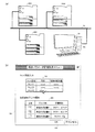
ここで、図6は、横軸にクラーク剛度、縦軸に填料の配合量(%)を示し、所定のクラーク剛度、填料の配合量に対する補正係数を示している。補正係数は、実施例1と同様に、0.5から1.6の範囲となっている。補正係数は、剛度が小さいほど小さい値が設定され、填料の配合量が少ないほど小さい値が設定される。例えば、メニュー画面から入力されたクラーク剛度が120以上で125未満であり、填料の配合量が14以上で15未満である場合、補正係数は0.9となる。この結果、ページ数、回転数のいずれの積算方式においても、離型性層211Sの摩耗量を更に精度よく予測することができる。ページ数基準で予測演算した結果を、図3(f)に示す。図3(f)は、横軸に摩耗量の予測値(10−4μm/Page)、縦軸に摩耗量の実測値(10−4μm/Page)を示すグラフである。本実施例の予測演算で得られた相関係数R2は0.92であり、填料の配合量を予測演算に加味することで予測値の精度が向上する。したがって、本実施例の演算結果に基づき行う寿命演算の精度も向上させることができる。
Here, FIG. 6 shows the Clark stiffness on the horizontal axis, the blending amount (%) of the filler on the vertical axis, and the correction coefficient for the predetermined Clark stiffness and the blending amount of the filler. The correction coefficient is in the range of 0.5 to 1.6 as in the first embodiment. The correction coefficient is set to a smaller value as the stiffness is smaller, and is set to a smaller value as the blending amount of the filler is smaller. For example, when the Clark stiffness input from the menu screen is 120 or more and less than 125 and the blending amount of the filler is 14 or more and less than 15, the correction coefficient is 0.9. As a result, the wear amount of the
以上説明したように、本実施例によれば、記録材の剛度及び填料の配合量に応じて定着部21の劣化度合いを精度よく予測演算することが可能となり、使用状況に応じた定着部21の寿命演算を精度よく行うことができる。また、本実施例では、給紙カセット毎に記録材Pの剛度及び填料の配合量を保持している。これにより、複数の紙種を用いるような場合でも、それぞれの記録材に応じた予測演算が可能となるため、ユーザの使用状況をより詳細に反映した精度よい結果を得ることができる。
As described above, according to the present embodiment, it is possible to accurately predict and calculate the degree of deterioration of the fixing
なお、本実施例では、各給紙カセットに対して記録材Pの剛度及び填料の配合量を保持しているが、例えば、図6のマトリクスから求めた補正係数を、給紙カセット毎に記憶しておくようにしてもよい。また、本実施例は、剛度及び填料の配合量の両方のデータがコントロールパネル35から入力される構成である。しかし、例えば、剛度は実施例1に示したように測距センサ40の検知結果に応じて自動で検出し、填料の配合量のみがコントロールパネル35から入力される構成としてもよい。また、填料の配合量を検出する検出手段が備えられている場合には、填料の配合量をその検出手段により自動で検出して前述した予測演算に用いることもできる。そして、このようなコントロールパネル35からの入力は、管理ユーザのみがアクセスできるメニュー画面から入力されるだけでなく、必要に応じて一般ユーザがアクセスできるメニュー画面から入力される構成としてもよい。
In this embodiment, the rigidity of the recording material P and the blending amount of the filler are held for each paper feed cassette. For example, the correction coefficient obtained from the matrix in FIG. 6 is stored for each paper feed cassette. You may make it keep. In addition, the present embodiment is configured such that data of both the stiffness and the blending amount of the filler are input from the
以上、本実施例によれば、搬送される記録材に応じて搬送手段の性能の低下の度合いを精度よく見積もることができる。 As described above, according to the present embodiment, it is possible to accurately estimate the degree of deterioration in the performance of the conveying means according to the recording material to be conveyed.
ユーザが個々の画像形成装置に対して幾つもの記録材Pに関するパラメータを設定することで、ユーザビリティが低下するおそれがある。また、前述した通り、記録材Pの剛度や填料の配合量のデータは、画像形成装置の管理ユーザのみが把握していて、一般ユーザは知り得ない場合もある。この場合、これらのパラメータは、管理ユーザにより設定されることとなる。しかし、管理ユーザが複数の画像形成装置及び用紙を管理している場合、個々の画像形成装置に対して、同じ用紙のパラメータの設定を、何度も繰り返すこととなる。このような作業を一括して設定することができると、管理ユーザの作業効率を向上させることが可能になる。そこで、実施例3では、記録材の剛度及び填料の配合量のデータを、ネットワーク回線を介してホスト装置から入力する構成について説明する。 When the user sets a number of parameters relating to the recording material P for each image forming apparatus, the usability may be reduced. Further, as described above, the data of the stiffness of the recording material P and the blending amount of the filler is known only by the management user of the image forming apparatus and may not be known by the general user. In this case, these parameters are set by the management user. However, when the management user manages a plurality of image forming apparatuses and sheets, the same sheet parameter setting is repeated many times for each image forming apparatus. If such work can be set collectively, the work efficiency of the management user can be improved. Therefore, in the third embodiment, a configuration in which data on the stiffness of the recording material and the blending amount of the filler is input from the host device via the network line will be described.
図7(a)は、本実施例の複数の画像形成装置100A〜100Cとホスト装置50の接続状況を示す図である。画像形成装置100Aから画像形成装置100Cは、いずれも、ネットワーク接続装置55を介してネットワーク回線60に接続されている。ホスト装置50は、設定手段である制御部50aを有している。ホスト装置50は、制御部50aにより、ネットワーク回線60を経由して、画像形成装置100A〜100Cの給紙カセット15毎に記録材Pの剛度及び填料の配合量データを入力することが可能となっている。画像形成装置100Aから画像形成装置100Cでは、ネットワーク接続装置55は制御演算部10と接続されており、ネットワーク回線60経由で入力された剛度及び填料の配合量データは、記憶手段としても機能する制御演算部10に保持される。なお、画像形成装置100Aから画像形成装置100Cの構成及び動作、劣化度合いの演算等については、実施例1、2で説明した構成と同様であり、同じ構成には同じ符号を付し、説明を省略する。
FIG. 7A is a diagram illustrating a connection state between the plurality of
ホスト装置50は、画像形成装置100Aから画像形成装置100Cと同一のネットワーク回線60に接続され、画像形成装置100Aから画像形成装置100Cの設定を一括管理したり、動作状況を監視したりすることが可能となっている。ホスト装置50から記録材Pの剛度及び填料の配合量のデータを送信する際には、例えば、図7(b)に示すような管理画面を用いて、送信先となる画像形成装置を選択する。
The
図7(b)は管理画面351を示す図である。管理画面351には、「用紙パラメータ管理設定メニュー」として、トレイ設定入力352と、設定送信プリンタ選択353とを入力することができる。トレイ設定入力352では、給紙カセット15Aから給紙カセット15Cに対応するトレイ1からトレイ3にセットされた記録材Pについて、剛度と填料の配合量を入力できるようになっている。また、設定送信プリンタ選択353では、画像形成装置100Aから画像形成装置100Cの設置場所の情報が表示されている。設定送信プリンタ選択353では、トレイ設定入力352で設定した剛度及び填料の配合量のデータを、どの画像形成装置に送信するかをチェックボックスにて設定できるようになっている。なお、本実施例では、管理画面351により剛度及び填料の配合量のデータを設定する構成となっているが、剛度と填料の配合量の少なくとも一方を設定する構成としてもよい。例えば、填料の配合量は管理画面351から入力され、剛度は測距センサ40の検知結果に基づき求められる構成とし、これらの値を用いて劣化度合いが演算される構成としてもよい。さらに、剛度が管理画面351から入力されている場合であっても、測距センサ40の検知結果に基づく剛度を用いて、劣化度合いを演算してもよい。
FIG. 7B shows the
例えば、図7(b)では、画像形成装置100Aに対応する画像形成装置1と画像形成装置100Bに対応する画像形成装置2にチェックがついている。このため、画像形成装置1と画像形成装置2の、それぞれのトレイ1からトレイ3までについては、共通の剛度、填料の配合量が設定される。ホスト装置50の制御部50aは、ユーザによりこれらのデータが入力された後、OKボタン354が押下されることにより、これらの情報を対応する各画像形成装置100A〜100Cの制御演算部10に送信する。これにより、ホスト装置50は、画像形成装置100A〜100Cを一括で管理することができる。なお、本実施例では、剛度及び填料の配合量のデータが入力される構成であるが、剛度及び填料の配合量の少なくともいずれか一方が入力される構成であればよい。
For example, in FIG. 7B, the image forming apparatus 1 corresponding to the
画像形成装置の個体識別情報には、予め画像形成装置に対して登録されているIPアドレスを用いる等、公知の方法で個体識別を行うことが可能である。このようにして管理画面351から選択した複数台の画像形成装置に対して、ホスト装置50は記録材Pの剛度及び填料の配合量のデータを、給紙カセット15毎に一括送信する。
The individual identification information of the image forming apparatus can be identified by a known method such as using an IP address registered in advance with the image forming apparatus. In this way, the
このように、ネットワーク回線60を経由して入力された記録材Pの剛度及び填料の配合量のデータを用いて、各画像形成装置の制御演算部10は、定着部21の寿命演算を精度よく行うことができる。また、各画像形成装置で行われた寿命演算の結果は、ネットワーク回線60を経由してホスト装置50に送信される。これにより、ホスト装置50は、各画像形成装置の定着部21の寿命演算結果を保守管理情報の一つとして保持することができるので、管理ユーザの管理負荷を軽減することもできる。
As described above, the
以上説明したように、画像形成装置の管理システムを構成することで、使用する用紙も含めて管理ユーザが管理する複数の画像形成装置に対して、記録材の剛度及び填料の配合量のデータを一度の作業で入力することが可能となる。これにより、管理ユーザの作業負荷を大きく低減させることが可能となる。 As described above, by configuring the management system of the image forming apparatus, data on the stiffness of the recording material and the blending amount of the filler for the plurality of image forming apparatuses managed by the management user including the paper to be used. It becomes possible to input by one operation. Thereby, it becomes possible to greatly reduce the workload of the management user.
以上、これまで説明した各実施例では、劣化度合いの予測演算を行う対象として加熱フィルム211を用いたが、本発明はこれに限定されるものでなく、例えば加熱フィルム211以外に、定着部21を構成する部品である加圧ローラ21aに適用してもよい。また、定着部21の寿命演算には加熱フィルム211の摩耗量の予測演算値のみを用いたが、上述した定着部21を構成する他の部品の劣化度合いなどを総合的に考慮して寿命演算を行うようにしてもよい。また、定着部21以外にも、例えば、二次転写ローラ25や給紙ローラ17、18等、記録材Pの表面に当接して記録材Pの搬送に寄与する回転搬送手段全般に適用することが可能である。
As described above, in each of the embodiments described so far, the
以上、本実施例によれば、搬送される記録材に応じて搬送手段の性能の低下の度合いを精度よく見積もることができる。 As described above, according to the present embodiment, it is possible to accurately estimate the degree of deterioration in the performance of the conveying means according to the recording material to be conveyed.
10 制御演算部
21b 加熱回転体
10
Claims (18)
前記搬送手段の劣化度合いを演算する演算手段と、
を備え、
前記演算手段は、前記劣化度合いを演算する際に、記録材の剛度に応じた補正を行うことを特徴とする画像形成装置。 Conveying means for conveying the recording material;
Computing means for computing the degree of deterioration of the conveying means;
With
The image forming apparatus according to claim 1, wherein the calculation unit performs correction according to the stiffness of the recording material when calculating the degree of deterioration.
前記演算手段は、前記検出手段により検出されたたわみ量が大きいほど、前記係数を小さい値に設定することを特徴とする請求項3に記載の画像形成装置。 A detecting means for detecting the amount of deflection of the recording material;
The image forming apparatus according to claim 3, wherein the arithmetic unit sets the coefficient to a smaller value as the deflection amount detected by the detection unit is larger.
前記複数の載置部の各々に載置された記録材についての剛度及び填料の配合量の少なくとも一方を、前記複数の載置部の各々に対応付けて記憶する記憶手段と、
を備えることを特徴とする請求項4又は請求項7に記載の画像形成装置。 A plurality of placement portions for placing recording materials;
Storage means for storing at least one of the stiffness and the blending amount of the filler for each of the plurality of placement units in association with each of the plurality of placement units;
The image forming apparatus according to claim 4, further comprising:
前記画像形成装置は、
記録材を載置する複数の載置部と、
記録材を搬送する搬送手段と、
前記搬送手段の劣化度合いを演算する演算手段と、
を有し、
前記管理装置は、
前記複数の画像形成装置の前記複数の載置部の各々に載置された記録材についての剛度を、前記複数の載置部の各々に対して一括して設定することが可能な設定手段を有し、
前記演算手段は、前記設定手段により設定された前記剛度に基づいて前記劣化度合いを演算し、演算した前記劣化度合いに基づいて前記搬送手段の寿命演算を行うことを特徴とする管理システム。 A management system comprising a plurality of image forming apparatuses, and a management apparatus connected to the plurality of image forming apparatuses via a network line,
The image forming apparatus includes:
A plurality of placement portions for placing recording materials;
Conveying means for conveying the recording material;
Computing means for computing the degree of deterioration of the conveying means;
Have
The management device
A setting unit capable of collectively setting the stiffness of the recording material placed on each of the plurality of placement units of the plurality of image forming apparatuses with respect to each of the plurality of placement units; Have
The management system calculates the deterioration degree based on the stiffness set by the setting means, and calculates the life of the conveying means based on the calculated deterioration degree.
前記演算手段は、前記検出手段により検出されたたわみ量が大きいほど、前記係数を小さい値に設定することを特徴とする請求項12に記載の管理システム。 A detecting means for detecting the amount of deflection of the recording material;
The management system according to claim 12, wherein the calculation unit sets the coefficient to a smaller value as the deflection amount detected by the detection unit is larger.
前記演算手段は、前記検出手段により検出されたたわみ量が大きいほど、前記係数を小さい値に設定することを特徴とする請求項15に記載の管理システム。 A detecting means for detecting the amount of deflection of the recording material;
The management system according to claim 15, wherein the calculation unit sets the coefficient to a smaller value as the deflection amount detected by the detection unit is larger.
Priority Applications (3)
| Application Number | Priority Date | Filing Date | Title |
|---|---|---|---|
| JP2015213021A JP2017083702A (en) | 2015-10-29 | 2015-10-29 | Image forming apparatus and management system |
| US15/334,643 US9989899B2 (en) | 2015-10-29 | 2016-10-26 | Image forming apparatus and management system |
| US15/966,084 US10409204B2 (en) | 2015-10-29 | 2018-04-30 | Image forming apparatus and management system |
Applications Claiming Priority (1)
| Application Number | Priority Date | Filing Date | Title |
|---|---|---|---|
| JP2015213021A JP2017083702A (en) | 2015-10-29 | 2015-10-29 | Image forming apparatus and management system |
Publications (2)
| Publication Number | Publication Date |
|---|---|
| JP2017083702A true JP2017083702A (en) | 2017-05-18 |
| JP2017083702A5 JP2017083702A5 (en) | 2018-12-06 |
Family
ID=58711851
Family Applications (1)
| Application Number | Title | Priority Date | Filing Date |
|---|---|---|---|
| JP2015213021A Pending JP2017083702A (en) | 2015-10-29 | 2015-10-29 | Image forming apparatus and management system |
Country Status (1)
| Country | Link |
|---|---|
| JP (1) | JP2017083702A (en) |
Cited By (2)
| Publication number | Priority date | Publication date | Assignee | Title |
|---|---|---|---|---|
| JP2017136443A (en) * | 2017-04-20 | 2017-08-10 | 株式会社大都技研 | Game machine |
| US11454913B2 (en) | 2020-07-09 | 2022-09-27 | Canon Kabushiki Kaisha | Image forming apparatus and image forming system |
Citations (13)
| Publication number | Priority date | Publication date | Assignee | Title |
|---|---|---|---|---|
| JPS63160938A (en) * | 1986-12-24 | 1988-07-04 | Minolta Camera Co Ltd | Image forming device |
| JP2003107944A (en) * | 2001-09-28 | 2003-04-11 | Konica Corp | Image forming device |
| JP2005326696A (en) * | 2004-05-14 | 2005-11-24 | Ricoh Co Ltd | Image forming apparatus |
| JP2009113973A (en) * | 2007-11-09 | 2009-05-28 | Kyocera Mita Corp | Image forming device |
| JP2009186684A (en) * | 2008-02-05 | 2009-08-20 | Ricoh Co Ltd | Image forming apparatus |
| JP2012189688A (en) * | 2011-03-09 | 2012-10-04 | Ricoh Co Ltd | Device for determining deterioration of rotation member, fixing device, and image forming device |
| JP2012255902A (en) * | 2011-06-09 | 2012-12-27 | Konica Minolta Business Technologies Inc | Fixing device and image forming apparatus |
| CN103116258A (en) * | 2011-11-16 | 2013-05-22 | 柯尼卡美能达商用科技株式会社 | Fixation unit and image forming apparatus |
| JP2014178344A (en) * | 2013-03-13 | 2014-09-25 | Ricoh Co Ltd | Image forming apparatus |
| JP2015001572A (en) * | 2013-06-14 | 2015-01-05 | コニカミノルタ株式会社 | Image forming apparatus and job management system |
| US20150185673A1 (en) * | 2013-12-31 | 2015-07-02 | Lexmark International, Inc. | Method of using an imaging device having a media stiffness sensor assembly |
| JP2015129823A (en) * | 2014-01-07 | 2015-07-16 | コニカミノルタ株式会社 | Damage amount determination apparatus, image forming apparatus, damage amount determination program, and damage amount determination method |
| JP2015176399A (en) * | 2014-03-17 | 2015-10-05 | 株式会社リコー | Information processor, information processing system, information processing method, program and image formation system |
-
2015
- 2015-10-29 JP JP2015213021A patent/JP2017083702A/en active Pending
Patent Citations (13)
| Publication number | Priority date | Publication date | Assignee | Title |
|---|---|---|---|---|
| JPS63160938A (en) * | 1986-12-24 | 1988-07-04 | Minolta Camera Co Ltd | Image forming device |
| JP2003107944A (en) * | 2001-09-28 | 2003-04-11 | Konica Corp | Image forming device |
| JP2005326696A (en) * | 2004-05-14 | 2005-11-24 | Ricoh Co Ltd | Image forming apparatus |
| JP2009113973A (en) * | 2007-11-09 | 2009-05-28 | Kyocera Mita Corp | Image forming device |
| JP2009186684A (en) * | 2008-02-05 | 2009-08-20 | Ricoh Co Ltd | Image forming apparatus |
| JP2012189688A (en) * | 2011-03-09 | 2012-10-04 | Ricoh Co Ltd | Device for determining deterioration of rotation member, fixing device, and image forming device |
| JP2012255902A (en) * | 2011-06-09 | 2012-12-27 | Konica Minolta Business Technologies Inc | Fixing device and image forming apparatus |
| CN103116258A (en) * | 2011-11-16 | 2013-05-22 | 柯尼卡美能达商用科技株式会社 | Fixation unit and image forming apparatus |
| JP2014178344A (en) * | 2013-03-13 | 2014-09-25 | Ricoh Co Ltd | Image forming apparatus |
| JP2015001572A (en) * | 2013-06-14 | 2015-01-05 | コニカミノルタ株式会社 | Image forming apparatus and job management system |
| US20150185673A1 (en) * | 2013-12-31 | 2015-07-02 | Lexmark International, Inc. | Method of using an imaging device having a media stiffness sensor assembly |
| JP2015129823A (en) * | 2014-01-07 | 2015-07-16 | コニカミノルタ株式会社 | Damage amount determination apparatus, image forming apparatus, damage amount determination program, and damage amount determination method |
| JP2015176399A (en) * | 2014-03-17 | 2015-10-05 | 株式会社リコー | Information processor, information processing system, information processing method, program and image formation system |
Cited By (2)
| Publication number | Priority date | Publication date | Assignee | Title |
|---|---|---|---|---|
| JP2017136443A (en) * | 2017-04-20 | 2017-08-10 | 株式会社大都技研 | Game machine |
| US11454913B2 (en) | 2020-07-09 | 2022-09-27 | Canon Kabushiki Kaisha | Image forming apparatus and image forming system |
Similar Documents
| Publication | Publication Date | Title |
|---|---|---|
| JP6324041B2 (en) | Image forming apparatus and image forming system | |
| US10409204B2 (en) | Image forming apparatus and management system | |
| US10274875B2 (en) | Image forming apparatus and management system for calculating a degree of deterioration of a fixing portion | |
| JP5310613B2 (en) | Image processing apparatus and image processing apparatus control method | |
| JP2015034807A (en) | Image inspection device, image inspection method and program | |
| JP6679272B2 (en) | Image forming apparatus and management system | |
| JP2017083702A (en) | Image forming apparatus and management system | |
| US10877421B2 (en) | Image forming apparatus and image forming method | |
| JP2012242625A (en) | Image forming apparatus and curl prediction method | |
| JP2010249872A (en) | Image forming apparatus | |
| US10317834B2 (en) | Image forming apparatus | |
| US10705467B2 (en) | Image forming apparatus capable of evaluating the consumption of a fixing belt, control method and control program thereof | |
| US11454913B2 (en) | Image forming apparatus and image forming system | |
| JP4870637B2 (en) | Image forming apparatus | |
| US20230393515A1 (en) | Image forming system | |
| JP2019179087A (en) | Fixing device and image forming apparatus | |
| JP2019074723A (en) | Image forming apparatus, method for controlling image forming apparatus, and program | |
| US20240094669A1 (en) | Image forming apparatus and image forming system | |
| JP6641956B2 (en) | Image forming apparatus, image forming system and method for suppressing occurrence of tacking | |
| US9958814B2 (en) | Image forming apparatus with function for determining recording material stiffness | |
| JP2022054369A (en) | Image forming apparatus | |
| JP2015176071A (en) | image forming apparatus | |
| JP2020071278A (en) | Image formation apparatus | |
| JP2019086657A (en) | Image forming apparatus, calculation method, and calculation program | |
| JP2021067891A (en) | Image forming apparatus |
Legal Events
| Date | Code | Title | Description |
|---|---|---|---|
| RD03 | Notification of appointment of power of attorney |
Free format text: JAPANESE INTERMEDIATE CODE: A7423 Effective date: 20160215 |
|
| RD04 | Notification of resignation of power of attorney |
Free format text: JAPANESE INTERMEDIATE CODE: A7424 Effective date: 20160215 |
|
| RD04 | Notification of resignation of power of attorney |
Free format text: JAPANESE INTERMEDIATE CODE: A7424 Effective date: 20171201 |
|
| A521 | Request for written amendment filed |
Free format text: JAPANESE INTERMEDIATE CODE: A523 Effective date: 20181026 |
|
| A621 | Written request for application examination |
Free format text: JAPANESE INTERMEDIATE CODE: A621 Effective date: 20181026 |
|
| A131 | Notification of reasons for refusal |
Free format text: JAPANESE INTERMEDIATE CODE: A131 Effective date: 20190813 |
|
| A977 | Report on retrieval |
Free format text: JAPANESE INTERMEDIATE CODE: A971007 Effective date: 20190814 |
|
| A02 | Decision of refusal |
Free format text: JAPANESE INTERMEDIATE CODE: A02 Effective date: 20200225 |