JP2017079110A - Fuel cell system - Google Patents
Fuel cell system Download PDFInfo
- Publication number
- JP2017079110A JP2017079110A JP2015205651A JP2015205651A JP2017079110A JP 2017079110 A JP2017079110 A JP 2017079110A JP 2015205651 A JP2015205651 A JP 2015205651A JP 2015205651 A JP2015205651 A JP 2015205651A JP 2017079110 A JP2017079110 A JP 2017079110A
- Authority
- JP
- Japan
- Prior art keywords
- fuel
- fuel cell
- gas
- supply pipe
- gas supply
- Prior art date
- Legal status (The legal status is an assumption and is not a legal conclusion. Google has not performed a legal analysis and makes no representation as to the accuracy of the status listed.)
- Granted
Links
Images

Classifications
-
- Y—GENERAL TAGGING OF NEW TECHNOLOGICAL DEVELOPMENTS; GENERAL TAGGING OF CROSS-SECTIONAL TECHNOLOGIES SPANNING OVER SEVERAL SECTIONS OF THE IPC; TECHNICAL SUBJECTS COVERED BY FORMER USPC CROSS-REFERENCE ART COLLECTIONS [XRACs] AND DIGESTS
- Y02—TECHNOLOGIES OR APPLICATIONS FOR MITIGATION OR ADAPTATION AGAINST CLIMATE CHANGE
- Y02E—REDUCTION OF GREENHOUSE GAS [GHG] EMISSIONS, RELATED TO ENERGY GENERATION, TRANSMISSION OR DISTRIBUTION
- Y02E60/00—Enabling technologies; Technologies with a potential or indirect contribution to GHG emissions mitigation
- Y02E60/30—Hydrogen technology
- Y02E60/50—Fuel cells
Landscapes
- Fuel Cell (AREA)
Abstract
【課題】制御部の制御の停止後に、補助部内の混合排ガスが燃料室に逆流することに起因して燃料極が酸化することを抑制すること。【解決手段】燃料電池システムにおいて、酸化剤ガス供給管に設けられ、電力供給が停止された場合、酸化剤ガス供給管内の流路を閉鎖する閉鎖状態になり、電力供給がされた場合、閉鎖状態から酸化剤ガス供給管内の流路を開放する開放状態に切り替わる第1の開閉部と、燃料ガス供給管に設けられた第1の逆止弁と、を備える。【選択図】図1An object of the present invention is to suppress the oxidation of a fuel electrode due to the backflow of mixed exhaust gas in an auxiliary part to a fuel chamber after the control of a control part is stopped. In the fuel cell system, when the power supply is stopped when the oxidant gas supply pipe is provided, the flow path in the oxidant gas supply pipe is closed, and when the power supply is performed, the fuel cell system is closed. A first open / close portion that switches from an open state to open the flow path in the oxidant gas supply pipe and a first check valve provided in the fuel gas supply pipe. [Selection] Figure 1
Description
本明細書に開示される技術は、燃料電池システムに関する。 The technology disclosed in this specification relates to a fuel cell system.
燃料電池システムは、複数の単セルを含む燃料電池スタックと、酸化剤ガス供給源と、酸化剤ガス供給管と、燃料ガス供給源と、燃料ガス供給管と、補助部と、制御部とを備える。燃料電池スタックには、各単セルの空気極に面する空気室に連通する酸化剤ガス流路と、各単セルの燃料極に面する燃料室に連通する燃料ガス流路とが形成されている。酸化剤ガス供給源は、酸化剤ガス供給管を介して、燃料電池スタックの酸化剤ガス流路に接続されており、酸化剤ガスを空気室に供給する。燃料ガス供給源は、燃料ガス供給管を介して、燃料電池スタックの燃料ガス流路に接続されており、燃料ガスを燃料室に供給する。補助部は、燃料電池スタックから排出される酸化剤オフガスと燃料オフガスとが合流する合流空間が形成されている。制御部は、酸化剤ガス供給源による酸化剤ガスの供給量と、燃料ガス供給源による燃料ガスの供給量とを制御する。 The fuel cell system includes a fuel cell stack including a plurality of single cells, an oxidant gas supply source, an oxidant gas supply pipe, a fuel gas supply source, a fuel gas supply pipe, an auxiliary unit, and a control unit. Prepare. The fuel cell stack is formed with an oxidant gas flow path communicating with the air chamber facing the air electrode of each single cell and a fuel gas flow path communicating with the fuel chamber facing the fuel electrode of each single cell. Yes. The oxidant gas supply source is connected to the oxidant gas flow path of the fuel cell stack via the oxidant gas supply pipe, and supplies the oxidant gas to the air chamber. The fuel gas supply source is connected to the fuel gas flow path of the fuel cell stack via the fuel gas supply pipe, and supplies the fuel gas to the fuel chamber. The auxiliary portion is formed with a merge space in which the oxidant off-gas discharged from the fuel cell stack and the fuel off-gas merge. The control unit controls the supply amount of the oxidant gas from the oxidant gas supply source and the supply amount of the fuel gas from the fuel gas supply source.
このような燃料電池システムでは、燃料電池スタックの発電動作が停止すると、補助部の合流空間内に存在する酸化剤オフガスと燃料オフガスとの混合ガス(以下、混合排ガスという)が燃料電池スタックの燃料室内に逆流し、混合排ガスに含まれる酸素によって燃料極が酸化するおそれがある。そこで、燃料電池スタックの発電動作が停止する場合、酸化剤ガス供給源および燃料ガス供給源の供給量を制御部により制御して、混合排ガスが補助部から各単セルの燃料室内に逆流しないようにする技術が提案されている(特許文献1参照)。 In such a fuel cell system, when the power generation operation of the fuel cell stack is stopped, a mixed gas of an oxidant off-gas and a fuel off-gas (hereinafter referred to as a mixed exhaust gas) present in the merging space of the auxiliary unit is the fuel of the fuel cell stack. There is a risk that the fuel electrode may oxidize due to oxygen flowing back into the room and oxygen contained in the mixed exhaust gas. Therefore, when the power generation operation of the fuel cell stack is stopped, the supply amounts of the oxidant gas supply source and the fuel gas supply source are controlled by the control unit so that the mixed exhaust gas does not flow backward from the auxiliary unit into the fuel chamber of each single cell. The technique to make is proposed (refer patent document 1).
上記従来の燃料電池システムでは、制御部の制御によって燃料極の酸化を抑制しているため、例えば停電等によって制御部が酸化剤ガス供給源および燃料ガス供給源を正常に制御できなくなった場合や、エラー検知により制御部が酸化剤ガス供給源および燃料ガス供給源の制御を停止した場合などには、燃料極の酸化を抑制することができないおそれがある。 In the above conventional fuel cell system, since the oxidation of the fuel electrode is suppressed by the control of the control unit, for example, when the control unit becomes unable to control the oxidant gas supply source and the fuel gas supply source normally due to a power failure or the like, When the control unit stops controlling the oxidant gas supply source and the fuel gas supply source due to error detection, there is a possibility that the oxidation of the fuel electrode cannot be suppressed.
本明細書では、上述した課題の少なくとも一部を解決することが可能な技術を開示する。 The present specification discloses a technique capable of solving at least a part of the problems described above.
本明細書に開示される技術は、以下の形態として実現することが可能である。 The technology disclosed in this specification can be implemented as the following forms.
(1)本明細書に開示される燃料電池システムは、固体酸化物または炭酸塩を含む電解質層と、前記電解質層を挟んで互いに対向する空気極および燃料極とを含む単セルを複数備える燃料電池スタックであって、前記空気極に面する空気室に連通する酸化剤ガス流路と、前記燃料極に面する燃料室に連通する燃料ガス流路とが形成された燃料電池スタックと、酸化剤ガスを送出する酸化剤ガス供給源と、一端が前記酸化剤ガス供給源に接続され、他端が前記酸化剤ガス流路に接続される酸化剤ガス供給管と、燃料ガスを送出する燃料ガス供給源と、一端が前記燃料ガス供給源に接続され、他端が前記燃料ガス流路に接続される燃料ガス供給管と、前記燃料電池スタックから排出される前記酸化剤ガスを含む酸化剤オフガスと前記燃料ガスを含む燃料オフガスとが合流する合流空間が形成された補助部と、前記酸化剤ガス供給源および前記燃料ガス供給源を制御する制御部と、を備える燃料電池システムにおいて、前記酸化剤ガス供給管に設けられ、電力供給が停止された場合、前記酸化剤ガス供給管内の流路を閉鎖する閉鎖状態になり、電力供給がされた場合、前記閉鎖状態から前記酸化剤ガス供給管内の流路を開放する開放状態に切り替わる第1の開閉部と、前記燃料ガス供給管に設けられた第1の逆止弁と、を備えることを特徴とする。この燃料電池システムによれば、何らかの原因で制御部の制御が停止すると、第1の開閉部に電力供給が停止されるため、第1の開閉部は閉鎖状態になり、酸化剤ガス供給源からの酸化剤ガスの供給が遮断される。また、燃料ガス供給管には第1の逆止弁が設けられているため、燃料ガスが燃料電池スタック側から燃料ガス供給源側に逆流することが抑制される。つまり、燃料電池システム内の酸化剤ガス流路のガスの圧力及び流量をいち早く低下させ、燃料ガス流路のガスの圧力及び流量を、酸化剤ガス流路のガスの圧力及び流量より大きい状態を作り出す。これにより、制御部の制御の停止後に、燃料電池スタックから排出される燃料オフガスは補助部内に供給されつつ、燃料電池スタックから排出される酸化剤オフガスが補助部内に流入する量が低減されるため、補助部内の混合排ガスの酸素濃度を低くすることができる。このため、仮に、混合排ガスが燃料室内に逆流しても、燃料極の酸化を抑制することができる。 (1) A fuel cell system disclosed in this specification is a fuel including a plurality of unit cells each including an electrolyte layer containing a solid oxide or a carbonate, and an air electrode and a fuel electrode facing each other with the electrolyte layer interposed therebetween. A fuel cell stack having a oxidant gas flow path communicating with the air chamber facing the air electrode and a fuel gas flow path communicating with the fuel chamber facing the fuel electrode; An oxidant gas supply source for sending an oxidant gas; an oxidant gas supply pipe having one end connected to the oxidant gas supply source and the other end connected to the oxidant gas flow path; and a fuel for sending fuel gas A gas supply source; a fuel gas supply pipe having one end connected to the fuel gas supply source and the other end connected to the fuel gas flow path; and an oxidant including the oxidant gas discharged from the fuel cell stack Including off-gas and fuel gas Provided in the oxidant gas supply pipe in a fuel cell system, comprising: an auxiliary part in which a merge space where the fuel off-gas merges is formed; and a control part that controls the oxidant gas supply source and the fuel gas supply source. When the power supply is stopped, the flow path in the oxidant gas supply pipe is closed, and when the power is supplied, the flow path in the oxidant gas supply pipe is opened from the closed state. A first opening / closing portion that switches to an open state and a first check valve provided in the fuel gas supply pipe are provided. According to this fuel cell system, when the control of the control unit is stopped for some reason, the power supply to the first opening / closing unit is stopped, so that the first opening / closing unit is closed and the oxidant gas supply source The supply of the oxidant gas is cut off. Further, since the first check valve is provided in the fuel gas supply pipe, the fuel gas is prevented from flowing back from the fuel cell stack side to the fuel gas supply source side. In other words, the pressure and flow rate of the gas in the oxidant gas flow path in the fuel cell system are quickly reduced, and the pressure and flow rate of the gas in the fuel gas flow path are set to be larger than the pressure and flow rate of the gas in the oxidant gas flow path. produce. Thereby, after the control of the control unit is stopped, the amount of the oxidant off-gas discharged from the fuel cell stack flows into the auxiliary unit while the fuel off-gas discharged from the fuel cell stack is supplied into the auxiliary unit. The oxygen concentration of the mixed exhaust gas in the auxiliary part can be lowered. For this reason, even if the mixed exhaust gas flows backward into the fuel chamber, the oxidation of the fuel electrode can be suppressed.
(2)上記燃料電池システムにおいて、前記第1の開閉部は、前記酸化剤ガス供給管における中間点よりも前記燃料電池スタック側に設けられていてもよい。この燃料電池システムによれば、第1の開閉部が、酸化剤ガス供給管における中間点よりも酸化剤ガス供給源側に設けられた場合に比べて、第1の開閉部が閉鎖状態になったときに第1の開閉部と燃料電池スタックとの間に残存する酸化剤ガスが少ない分だけ、酸化剤ガス流路のガスの圧力及び流量が大きくなることを抑制できる。これにより、制御部の制御の停止後に酸化剤オフガスが補助部内に流入する量が低減されるため、補助部内の混合排ガスの酸素濃度をさらに低下させ、燃料極の酸化を、より確実に抑制することができる。 (2) In the fuel cell system, the first opening / closing part may be provided closer to the fuel cell stack than an intermediate point in the oxidant gas supply pipe. According to this fuel cell system, the first opening / closing part is in a closed state as compared with the case where the first opening / closing part is provided closer to the oxidant gas supply source than the intermediate point in the oxidant gas supply pipe. Therefore, it is possible to prevent the gas pressure and flow rate in the oxidant gas flow path from increasing due to the small amount of oxidant gas remaining between the first opening / closing part and the fuel cell stack. As a result, the amount of the oxidant off-gas flowing into the auxiliary unit after the control unit is stopped is reduced, so that the oxygen concentration of the mixed exhaust gas in the auxiliary unit is further reduced, and the oxidation of the fuel electrode is more reliably suppressed. be able to.
(3)上記燃料電池システムにおいて、前記燃料ガス供給管の内、前記第1の逆止弁と前記燃料電池スタックとの間には、前記燃料ガス供給管の流路に直交する断面における開口面積が前記燃料ガス供給管よりも大きい収容空間が形成されたガス貯留部が設けられてもよい。この燃料電池システムによれば、燃料電池スタックの発電動作の停止後に燃料電池スタックの温度が低下して燃料電池スタック内の圧力が低下してきた場合でも、ガス貯留部に蓄えられた燃料ガスが燃料室内に供給され続けられるので、燃料ガス流路のガスの圧力及び流量の極端な減少を抑制し、混合排ガスが燃料室内に逆流することを抑制し、燃料極の酸化を抑制することができる。 (3) In the fuel cell system, an opening area in a cross section perpendicular to the flow path of the fuel gas supply pipe is provided between the first check valve and the fuel cell stack in the fuel gas supply pipe. However, there may be provided a gas storage part in which an accommodation space larger than the fuel gas supply pipe is formed. According to this fuel cell system, even when the temperature of the fuel cell stack decreases after the power generation operation of the fuel cell stack stops and the pressure in the fuel cell stack decreases, the fuel gas stored in the gas storage section is Since the gas is continuously supplied into the chamber, it is possible to suppress an extreme decrease in the pressure and flow rate of the gas in the fuel gas flow path, to prevent the mixed exhaust gas from flowing back into the fuel chamber, and to suppress oxidation of the fuel electrode.
(4)上記燃料電池システムにおいて、さらに、一端が前記補助部に形成された前記合流空間に接続され、他端が前記補助部の外部に引き出された排出管と、前記排出管に設けられた第2の逆止弁と、を備えてもよい。この燃料電池システムによれば、排出管には第2の逆止弁が設けられているため、外部の空気が補助部に形成された合流空間に流入することが抑制される構成としてもよい。これにより、外部の空気が排出管を介して補助部内に流入することに起因して混合排ガスの酸素濃度が高くなることを抑制し、燃料極の酸化を抑制することができる。 (4) In the fuel cell system, further, one end is connected to the joining space formed in the auxiliary portion, and the other end is provided in the discharge pipe drawn out of the auxiliary portion and the discharge pipe. A second check valve. According to this fuel cell system, since the second check valve is provided in the discharge pipe, it may be configured such that outside air is prevented from flowing into the merge space formed in the auxiliary portion. Thereby, it can suppress that the oxygen concentration of mixed exhaust gas becomes high resulting from external air flowing in into an auxiliary | assistant part via a discharge pipe, and can suppress the oxidation of a fuel electrode.
(5)上記燃料電池システムにおいて、さらに、前記燃料ガス供給管において、前記第1の逆止弁と前記燃料電池スタックとの間に設けられた改質部と、水を送出する水供給源と、一端が前記水供給源に接続され、他端が前記改質部に繋がっている水供給管と、前記水供給管に設けられたフィルタと、を備え、前記制御部は、前記水供給源を制御し、前記水供給管の内、前記フィルタと前記改質部との間に設けられ、電力供給が停止された場合、前記水供給管内の流路を閉鎖する閉鎖状態になり、電力供給がされた場合、前記閉鎖状態から前記水供給管内の流路を開放する開放状態に切り替わる第2の開閉部と、を備えてもよい。この燃料電池システムによれば、何らかの原因で制御部の制御が停止すると、第2の開閉部に電力供給が停止されるため、第2の開閉部は閉鎖状態になり、フィルタから改質部への水の供給が遮断される構成としてもよい。これにより、フィルタ内の水が改質部に供給され改質部から燃料室に水蒸気リッチな気体が流入することに起因して燃料極が酸化することを抑制することができる。 (5) In the fuel cell system, in the fuel gas supply pipe, a reforming unit provided between the first check valve and the fuel cell stack, a water supply source for sending water A water supply pipe having one end connected to the water supply source and the other end connected to the reforming unit, and a filter provided in the water supply pipe, and the control unit includes the water supply source Is provided between the filter and the reforming unit in the water supply pipe, and when the power supply is stopped, the flow path in the water supply pipe is closed, and the power supply A second opening / closing part that switches from the closed state to an open state that opens the flow path in the water supply pipe. According to this fuel cell system, when the control of the control unit stops for some reason, the power supply to the second opening / closing unit is stopped, so the second opening / closing unit is closed, and the filter is changed from the filter to the reforming unit. The water supply may be blocked. As a result, it is possible to suppress the fuel electrode from being oxidized due to the water in the filter being supplied to the reforming unit and the vapor-rich gas flowing from the reforming unit into the fuel chamber.
(6)上記燃料電池システムにおいて、前記第2の開閉部は、前記水供給管における中間点よりも前記改質部側に設けられてもよい。この燃料電池システムによれば、第2の開閉部が、水供給管における中間点よりも水供給源側に設けられた場合に比べて、第2の開閉部が閉鎖状態になったときに第2の開閉部と改質部との間に残存する水が少ない分だけ、制御部の制御の停止後に水蒸気リッチな気体が燃料極に流入することを、より確実に抑制することができる。 (6) In the fuel cell system, the second opening / closing part may be provided closer to the reforming part than an intermediate point in the water supply pipe. According to this fuel cell system, when the second opening / closing part is in a closed state, the second opening / closing part is closer to the water supply source than the intermediate point in the water supply pipe. The amount of water remaining between the open / close unit 2 and the reforming unit 2 can be more reliably suppressed from flowing into the fuel electrode by the water vapor-rich gas after the control of the control unit is stopped.
A.第1実施形態:
A−1.構成:
(燃料電池システム1の構成)
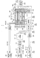
図1は、燃料電池システム1の構成を概略的に示す説明図である。図1には、後述する燃料電池スタック100については断面構成が示されている。本明細書では、便宜的に、紙面上方向(後述のオフガス燃焼部230から燃料電池スタック100に向かう方向)を上方向と呼び、紙面下方向を下方向と呼ぶものとするが、燃料電池スタック100は実際にはそのような向きとは異なる向きで設置されてもよい。燃料電池システム1は、燃料電池スタック100と、酸化剤ガスOGの供給側の構成と、原燃料ガスRFGの供給側の構成と、オフガスOOG,FOGの排出側の構成と、制御部700(図2参照)と、断熱容器800とを備える。
A. First embodiment:
A-1. Constitution:
(Configuration of fuel cell system 1)
FIG. 1 is an explanatory diagram schematically showing the configuration of the fuel cell system 1. FIG. 1 shows a cross-sectional configuration of a
(燃料電池スタック100の構成)
燃料電池スタック100は、複数の(本実施形態では2つの)発電単位102と、一対のエンドプレート104,106とを備える。2つの発電単位102は、所定の配列方向(本実施形態では上下方向)に並べて配置されている。一対のエンドプレート104,106は、2つの発電単位102を上下から挟むように配置されている。なお、燃料電池スタック100は、上下方向に延びる図示しない複数のボルトによって締結されている。
(Configuration of fuel cell stack 100)
The
燃料電池スタック100を構成する各層(発電単位102、エンドプレート104,106)の上下方向回りの周縁部には、上下方向に貫通する複数の孔が形成されており、各層に形成され互いに対応する孔同士が上下方向に連通して、酸化剤ガス導入マニホールド161と、酸化剤ガス排出マニホールド162と、燃料ガス導入マニホールド171と、燃料ガス排出マニホールド172とを構成している。
A plurality of holes penetrating in the vertical direction are formed in the peripheral portions of the respective layers (
酸化剤ガス導入マニホールド161は、燃料電池スタック100の外部から酸化剤ガスOGが導入され、その酸化剤ガスOGを各発電単位102に供給するガス流路であり、一方のエンドプレート104を貫通し、他方のエンドプレート106に向かって延びている。酸化剤ガス排出マニホールド162は、各発電単位102から排出された酸化剤オフガスOOGを燃料電池スタック100の外部へと排出するガス流路であり、一方のエンドプレート104の下面から、他方のエンドプレート106に向かって延び、当該他方のエンドプレート106を貫通している。なお、本実施形態では、酸化剤ガスOGとして空気が使用される。
The oxidant
燃料ガス導入マニホールド171は、燃料電池スタック100の外部から後述する燃料ガスFGが導入され、その燃料ガスFGを各発電単位102に供給するガス流路であり、他方のエンドプレート106を貫通し、一方のエンドプレート104に向かって延びている。燃料ガス排出マニホールド172は、各発電単位102から排出された燃料オフガスFOGを燃料電池スタック100の外部へと排出するガス流路であり、他方のエンドプレート106を貫通し、一方のエンドプレート104に向かって延びている。酸化剤ガス導入マニホールド161は、酸化剤ガス流路の一例であり、燃料ガス導入マニホールド171は、燃料ガス流路の一例である。
The fuel
一対のエンドプレート104,106は、方形の平板形状の導電性部材であり、例えばステンレスにより形成されている。一方のエンドプレート104は、最も上に位置する発電単位102の上側に配置され、他方のエンドプレート106は、最も下に位置する発電単位102の下側に配置されている。一対のエンドプレート104,106によって複数の発電単位102が押圧された状態で挟持されている。上側のエンドプレート104は、燃料電池スタック100のプラス側の出力端子として機能し、下側のエンドプレート106は、燃料電池スタック100のマイナス側の出力端子として機能する。
The pair of
発電単位102は、単セル110と、セパレータ120と、空気極側フレーム130と、図示しない空気極側集電体と、燃料極側フレーム140と、図示しない燃料極側集電体と、発電単位102の最上層および最下層を構成する一対のインターコネクタ150とを備えている。
The
インターコネクタ150は、方形の平板形状の導電性部材であり、例えばフェライト系ステンレスにより形成されている。インターコネクタ150は、発電単位102間の電気的導通を確保すると共に、発電単位102間での反応ガスの混合を防止する。なお、本実施形態では、2つの発電単位102が隣接して配置されている場合、1つのインターコネクタ150は、隣接する2つの発電単位102に共有されている。すなわち、ある発電単位102における上側のインターコネクタ150は、その発電単位102の上側に隣接する他の発電単位102における下側のインターコネクタ150と同一部材である。また、燃料電池スタック100は一対のエンドプレート104,106を備えているため、燃料電池スタック100において最も上に位置する発電単位102は上側のインターコネクタ150を備えておらず、最も下に位置する発電単位102は下側のインターコネクタ150を備えていない。図1では上端の発電単位102にはエンドプレート104が設けられ、発電単位102における最上層のインターコネクタ150は省略されている。下端の発電単位102には、エンドプレート106が設けられ、発電単位102における最下層のインターコネクタ150が省略されている。したがって、インターコネクタ150は1つしか図示されていない。
The
単セル110は、電解質層112と、電解質層112を挟んで上下方向(発電単位102が並ぶ配列方向)に互いに対向する空気極(カソード) 114および燃料極(アノード)116とを備える。なお、本実施形態の単セル110は、燃料極116で電解質層112および空気極114を支持する燃料極支持形の単セルである。
The
電解質層112は、方形の平板形状部材であり、例えば、YSZ(イットリア安定化ジルコニア)、ScSZ(スカンジア安定化ジルコニア)、SDC(サマリウムドープセリア)、GDC(ガドリニウムドープセリア)、ペロブスカイト型酸化物等の固体酸化物により形成されている。空気極114は、方形の平板形状部材であり、例えば、ペロブスカイト型酸化物(例えばLSCF(ランタンストロンチウムコバルト鉄酸化物)、LSM(ランタンストロンチウムマンガン酸化物)、LNF(ランタンニッケル鉄)) により形成されている。燃料極116は、方形の平板形状部材であり、例えば、Ni(ニッケル)、Niとセラミック粒子からなるサーメット、Ni基合金等により形成されている。このように、本実施形態の単セル110(発電単位102)は、電解質として固体酸化物を用いる固体酸化物形燃料電池(SOFC)である。
The
セパレータ120は、中央付近に上下方向に貫通する方形の孔121が形成されたフレーム状の部材であり、例えば、金属により形成されている。セパレータ120における孔121の周囲部分は、電解質層112における空気極114の側の表面の周縁部に対向している。セパレータ120は、その対向した部分に配置されたロウ材(例えばAgロウ)により形成された図示しない接合部により、電解質層112(単セル110)と接合されている。セパレータ120により、単セル110の周縁部における一方の電極側から他方の電極側へのガスのリークが抑制される。なお、セパレータ120が接合された単セル110をセパレータ付き単セルともいう。
The
空気極側フレーム130は、中央付近に上下方向に貫通する方形の孔131が形成されたフレーム状の部材であり、例えば、マイカ等の絶縁体により形成されている。空気極側フレーム130は、セパレータ120における電解質層112に対向する側とは反対側の表面の周縁部と、インターコネクタ150における空気極114に対向する側の表面の周縁部とに接触している。空気極側フレーム130によって、空気極114とインターコネクタ150との間に空気室166が確保されると共に、発電単位102に含まれる一対のインターコネクタ150間が電気的に絶縁される。また、空気極側フレーム130には、酸化剤ガス導入マニホールド161と空気室166とを連通する酸化剤ガス供給連通孔132と、空気室166と酸化剤ガス排出マニホールド162とを連通する酸化剤ガス排出連通孔133とが形成されている。
The air
燃料極側フレーム140は、中央付近に上下方向に貫通する方形の孔141が形成されたフレーム状の部材であり、例えば、金属により形成されている。燃料極側フレーム140は、セパレータ120における電解質層112に対向する側の表面の周縁部と、インターコネクタ150における燃料極116に対向する側の表面の周縁部とに接触している。燃料極側フレーム140によって、燃料極116とインターコネクタ150との間に燃料室176が確保される。また、燃料極側フレーム140には、燃料ガス導入マニホールド171と燃料室176とを連通する燃料ガス供給連通孔142と、燃料室176と燃料ガス排出マニホールド172とを連通する燃料ガス排出連通孔143とが形成されている。
The fuel
空気極側集電体は、空気極114における電解質層112に対向する側とは反対側の表面と、インターコネクタ150における空気極114に対向する側の表面とに接触することにより、空気極114とインターコネクタ150とを電気的に接続する。燃料極側集電体は、燃料極116とインターコネクタ150とを電気的に接続する。
The air electrode side current collector is in contact with the surface of the
(酸化剤ガスOGの供給側の構成)
酸化剤ガスOGの供給側の構成には、酸化剤ガス供給源300と、第1の開閉部310と、酸化剤ガス供給管320とが含まれる。酸化剤ガス供給源300は、例えばコンプレッサやポンプを有し、酸化剤ガスOGを送出する。また、酸化剤ガス供給源300は、制御部700の制御によって酸化剤ガスOGの送出量を変更可能である。第1の開閉部310は、電力供給がされていることを条件に開放状態になり、電力供給が停止されると閉鎖状態になる、いわゆるノーマルクローズ型の開閉部であり、例えば、ノーマルクローズ型の電磁弁やバルブである。
(Configuration of supply side of oxidant gas OG)
The configuration on the supply side of the oxidant gas OG includes an oxidant
酸化剤ガス供給管320は、第1の酸化剤ガス供給管321と、第2の酸化剤ガス供給管322とを含む。第1の酸化剤ガス供給管321の一端は、酸化剤ガス供給源300の送出口に接続され、第1の酸化剤ガス供給管321の他端は、第1の開閉部310の入力口に接続されている。第2の酸化剤ガス供給管322の一端は、第1の開閉部310の出力口に接続され、第2の酸化剤ガス供給管322の他端は、燃料電池スタック100の酸化剤ガス導入マニホールド161の導入口に接続されている。また、第1の開閉部310は、酸化剤ガス供給管320における中間点よりも燃料電池スタック100側に設けられている。
The oxidant
(原燃料ガスRFGの供給側の構成)
原燃料ガスRFGの供給側の構成には、燃料ガス供給源400と、脱硫部410と、第1の逆止弁420と、ガス貯留部430と、燃料ガス供給管440と、気化部210と、改質部220と、水供給源500と、フィルタ510と、第2の開閉部520と、水供給管530とが含まれる。
(Configuration on the supply side of the raw fuel gas RFG)
The configuration on the supply side of the raw fuel gas RFG includes a fuel
燃料ガス供給源400は、例えばコンプレッサやポンプを有し、原燃料ガスRFGを送出する。また、燃料ガス供給源400は、制御部700の制御によって原燃料ガスRFGの送出量を変更可能である。脱硫部410は、燃料ガス供給源400によって送出された原燃料ガスRFGから硫黄を除去する。
The fuel
第1の逆止弁420は、脱硫部410から出力された原燃料ガスRFGが燃料電池スタック100側に流入することを許容しつつ、原燃料ガスRFGが燃料電池スタック100側から脱硫部410側へと逆流することを阻止する。ガス貯留部430は、入力口と出力口とを有し、内部に収容空間431が形成された部材であり、ガス貯留部430の外形は例えば円柱状である。収容空間431について、燃料ガス供給管440の流路に直交する断面における開口面積は、燃料ガス供給管440よりも大きい。ガス貯留部430は、例えば、金属材料や樹脂材料(特にゴム)によって形成されたものであり、圧力変化によって変形する材料で形成されたものが好ましい。
The
燃料ガス供給管440は、第1の燃料ガス供給管441と、第2の燃料ガス供給管442と、第3の燃料ガス供給管443と、第4の燃料ガス供給管444と、第5の燃料ガス供給管445と、第6の燃料ガス供給管446とを含む。第1の燃料ガス供給管441の一端は、燃料ガス供給源400の送出口に接続され、第1の燃料ガス供給管441の他端は、脱硫部410の入力口に接続されている。第2の燃料ガス供給管442の一端は、脱硫部410の出力口に接続され、第2の燃料ガス供給管442の他端は、第1の逆止弁420の入力口に接続されている。
The fuel
第3の燃料ガス供給管443の一端は、第1の逆止弁420の出力口に接続され、第3の燃料ガス供給管443の他端は、ガス貯留部430の入力口に接続されている。第4の燃料ガス供給管444の一端は、ガス貯留部430の出力口に接続され、第4の燃料ガス供給管444の他端は、気化部210の入力口に接続されている。第5の燃料ガス供給管445の一端は、気化部210の出力口に接続され、第5の燃料ガス供給管445の他端は、改質部220の入力口に接続されている。第6の燃料ガス供給管446の一端は、改質部220の出力口に接続され、第6の燃料ガス供給管446の他端は、燃料ガス導入マニホールド171の導入口に接続されている。
One end of the third fuel
水供給源500は、例えばコンプレッサやポンプを有し、水RWを送出する。また、水供給源500は、制御部700の制御によって水RWの送出量を変更可能である。フィルタ510には、水を収容可能な収容空間511が内部に形成されており、フィルタ510は、水供給源500から送出された水RWを浄化して純水にする。第2の開閉部520は、電力供給がされていることを条件に開放状態になり、電力供給が停止されると閉鎖状態になる、いわゆるノーマルクローズ型の開閉部であり、例えば、ノーマルクローズ型の電磁弁やバルブである。また、第2の開閉部520は、水供給管530においてフィルタ510と燃料電池スタック100との中間点よりも燃料電池スタック100側に設けられている。
The
水供給管530は、第1の水供給管531と、第2の水供給管532と、第3の水供給管533とを含む。第1の水供給管531は、水供給源500の送出口に接続され、第1の水供給管531の他端は、フィルタ510の入力口に接続されている。第2の水供給管532の一端は、フィルタ510の出力口に接続され、第2の水供給管532の他端は、第2の開閉部520の入力口に接続されている。第3の水供給管533の一端は、第2の開閉部520の出力口に接続され、第3の水供給管533の他端は、気化部210の入力口に接続されている。
The
気化部210には、水導入室と、この水導入室に連通する混合室とを含む内部空間211が形成されている。第2の開閉部520を介して水導入室に流入した水RWは、図示しない加熱源によって加熱され気化されて水蒸気になる。水蒸気は混合室に流入し、ガス貯留部430を介して混合室に流入した原燃料ガスRFGと混ざり合い、その結果、混合ガスが生成される。改質部220は、改質室221が内部に形成されている。気化部210で生成された混合ガスは、図示しない加熱源によって加熱され、改質室221内で改質反応に供され、その結果、水素リッチな燃料ガスFGとなり、燃料ガス導入マニホールド171に供給される。
In the
(オフガスOOG,FOGの排出側の構成)
酸化剤オフガスOOGおよび燃料オフガスFOGの排出側の構成には、オフガス燃焼部230と、第2の逆止弁600と、排出管610とが含まれる。オフガス燃焼部230の内部には、酸化剤ガス排出マニホールド162と燃料ガス排出マニホールド172とに連通する合流空間231が形成されている。酸化剤ガス排出マニホールド162から排出される酸化剤オフガスOOGと、燃料ガス排出マニホールド172から排出される燃料オフガスFOGとは、合流空間231にて合流して混ざり合い、燃焼する。なお、合流空間231には、酸化剤オフガスOOGと燃料オフガスFOGとの燃焼を促進させる触媒が配置されている。オフガス燃焼部230は、補助部の一例である。
(Exhaust gas OOG, FOG discharge side configuration)
The configuration on the exhaust side of the oxidant off-gas OOG and the fuel off-gas FOG includes an off-
第2の逆止弁600は、オフガス燃焼部230から排出された酸化剤オフガスOOGおよび燃料オフガスFOGが燃料電池スタック100の外部に流出することを許容しつつ、外部の空気がオフガス燃焼部230側へと逆流することを阻止する。排出管610は、第1の排出管611と、第2の排出管612とを含む。第1の排出管611の一端は、オフガス燃焼部230の排出口に接続され、第1の排出管611の他端は、第2の逆止弁600の入力口に接続されている。第2の排出管612の一端は、第2の逆止弁600の出力口に接続され、第2の排出管612の他端が燃料電池システム1の外部に引き出されている。
The
断熱容器800は、例えばステンレスにより形成された筐体の内側面に断熱材が配置された構成を有する。上述の燃料電池スタック100と、気化部210と、改質部220と、オフガス燃焼部230とが、発電モジュールを構成する。この発電モジュールが断熱容器800内に収容されることにより、発電を行う際に発電モジュールが高温に維持される。本実施形態では、上述の燃料電池システム1の構成要素のうち、発電モジュールと、酸化剤ガス供給管320の一部と、燃料ガス供給管440の一部と、水供給管530の一部と、排出管610の一部とが断熱容器800内に収容されており、酸化剤ガス供給源300と、第1の開閉部310と、燃料ガス供給源400と、脱硫部410と、第1の逆止弁420と、ガス貯留部430と、水供給源500と、フィルタ510と、第2の開閉部520と、第2の逆止弁600とは断熱容器800の外部に配置されている。
The
(制御部の構成)
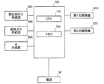
制御部700は、CPU710と、メモリ720とを有し、外部の電源Wから電力供給されることにより動作可能になる。メモリ720には、燃料電池システム1を制御するための制御プログラムや、各種設定等が記憶されている。CPU710は、メモリ720から読み出したプログラム等に従って、燃料電池システム1の各構成要素を制御する。
(Configuration of control unit)
The
より詳細には、CPU710は、酸化剤ガス供給源300の送出動作の入り切りを制御する。さらに、CPU710は、酸化剤ガス供給管320に設けられた図示しない圧力センサおよび流量センサの検出結果に基づき、酸化剤ガス供給源300による酸化剤ガスOGの送出圧力と送出量とを変更することにより、燃料電池スタック100(酸化剤ガス導入マニホールド161)に導入される酸化剤ガスOGの圧力および流量(以下、酸化剤ガスOGの導入圧力および導入流量という)を所定の目標値に調整する。また、CPU710は、燃料ガス供給源400の送出動作の入り切りを制御する。さらに、CPU710は、燃料ガス供給管440に設けられた図示しない圧力センサおよび流量センサの検出結果に基づき、燃料ガス供給源400による原燃料ガスRFGの送出圧力と送出量とを変更することにより、原燃料ガスRFGを改質部220により改質した燃料ガスFGの燃料電池スタック100(燃料ガス導入マニホールド171)に導入される圧力および流量(以下、燃料ガスFGの導入圧力および導入流量という)を所定の目標値に調整する。また、CPU710は、水供給源500の送出動作の入り切りを制御する。さらに、CPU710は、水供給管530に設けられた図示しない流量センサの検出結果に基づき、水供給源500による水RWの送出量を変更することにより、気化部210に導入される水RWの流量を所定の目標値に調整する。
More specifically, the
また、本実施形態では、第1の開閉部310および第2の開閉部520への電力供給の入り切りは、制御部700による制御に基づき行われる。従って、制御部700に電源Wからの電力供給が停止されると、第1の開閉部310および第2の開閉部520は閉鎖状態になる。
In the present embodiment, on / off of power supply to the first opening /
A−2.制御部700による制御不能または制御停止時の動作:
例えば停電、制御部700と電源Wとの間の電源ラインの断線や、制御部700自体の破損等が生じた場合、制御部700は、燃料電池システム1を正常に制御することができなくなる制御不能状態になる。また、例えば圧力センサの検出結果等に基づき酸化剤ガス供給源300や燃料ガス供給源400による送出圧力が異常値に達するなど、燃料電池システム1の異常状態を検出した場合は、燃料電池システム1の制御動作を強制終了(シャットダウン)し、電源Wからの電力供給を遮断する制御停止状態になる。
A-2. Operation when
For example, when a power failure, disconnection of a power supply line between the
ここで、後述するように、制御部700が制御不能状態や制御停止状態になり、燃料電池スタック100の発電動作が停止すると、オフガス燃焼部230の合流空間231内(以下、単に、オフガス燃焼部230内ということがある)に存在する酸化剤オフガスOOGと燃料オフガスFOGとの混合ガス(以下、混合排ガスという)が各発電単位102の燃料室176内に逆流し、混合排ガスに含まれる酸素によって燃料極116が酸化するおそれがある。本実施形態の燃料電池システム1では、制御部700が制御不能状態等になった場合でも、制御部700による制御を要することなく、燃料極116の酸化を抑制することができる。以下、燃料電池システム1の構成要素の内、第1の開閉部310、第1の逆止弁420、ガス貯留部430、第2の逆止弁600および第2の開閉部520が設けられていない構成を、比較構成Aとし、本実施形態の燃料電池システム1の作用効果について、比較構成Aと比較して説明する。
Here, as will be described later, when the
(第1の開閉部310と第1の逆止弁420とガス貯留部430とによる燃料極116の酸化の抑制)
制御部700が制御不能状態等になると、酸化剤ガス供給源300、燃料ガス供給源400および水供給源500への電力供給が停止される。しかし、酸化剤ガス供給源300、燃料ガス供給源400および水供給源500の惰性動作や、配管320,440,530内の残圧によって、酸化剤ガスOG、原燃料ガスRFGや水RWが惰性分だけ供給され続けることがある。
(Suppression of oxidation of
When the
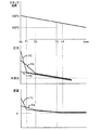
図3は、比較構成Aについて、制御部700による制御停止後における燃料電池スタック100の温度と、燃料電池スタック100内に導入されるガスの圧力および流量との推移を示す説明図である。図4は、本実施形態について、制御部700による制御停止後における燃料電池スタック100の温度と、燃料電池スタック100内に導入されるガスの圧力および流量との推移を示す説明図である。各図において、PCのグラフは、空気室166への酸化剤ガスOGの導入圧力の変化を示し、PAのグラフは、燃料室176への燃料ガスFGの導入圧力の変化を示し、PSのグラフは、オフガス燃焼部230内の圧力の変化を示す。また、FCのグラフは、空気室166への酸化剤ガスOGの導入流量の変化を示し、FAのグラフは、燃料室176への燃料ガスFGの導入流量の変化を示す。なお、図3に示すFA,FCのグラフにおいて、酸化剤ガスOGの導入流量および燃料ガスFGの導入流量がマイナスの範囲内にあることは、オフガス燃焼部230内の混合排ガスが燃料電池スタック100内(燃料室176等)に逆流していることを意味する。また、図4に示すFA,FCのグラフにおいて、酸化剤ガスOGの導入流量および燃料ガスFGの導入流量が0(ゼロ)であることは、酸化剤ガスOGおよび燃料ガスFGが燃料電池スタック100内に流入しておらず、さらに、オフガス燃焼部230内の混合排ガスが燃料電池スタック100内(燃料室176等)に逆流もしていないことを意味する。
FIG. 3 is an explanatory diagram showing the transition of the temperature of the
制御部700の制御動作中では、酸化剤ガスOGの導入圧力は、燃料ガスFGの導入圧力よりも高く、且つ、酸化剤ガスOGの導入流量は、燃料ガスFGの導入流量よりも多い。このため、比較構成Aでは、制御部700による制御が停止すると(図3の時間T0参照)、酸化剤ガスOGの導入圧力が燃料ガスFGの導入圧力よりも高い状態を維持しつつ、酸化剤ガスOGの導入圧力および燃料ガスFGの導入圧力が低下していく。また、酸化剤ガスOGの導入流量が燃料ガスFGの導入流量よりも多い状態を維持しつつ、酸化剤ガスOGの導入流量および燃料ガスFGの導入流量が低下していく(図3の時間T0と時間T2との期間を参照)。また、上述の制御部700による制御が停止すると、燃料電池スタック100の発電動作が停止し、各単セル110での発電反応が停止するため、燃料電池スタック100の温度が低下していく。
During the control operation of the
その後、燃料ガスFGの導入圧力が、酸化剤ガスOGの導入圧力より先にオフガス燃焼部230内の圧力と同等になることにより(図3の時間T2参照)、燃料オフガスFOGのオフガス燃焼部230内への流入量が、酸化剤オフガスOOGのオフガス燃焼部230内への流入量よりも早期にゼロに近くなる。すなわち、比較構成Aでは、制御部700による制御の停止後において、酸化剤オフガスOOGが、燃料オフガスFOGよりも、オフガス燃焼部230内に多く流入するため、オフガス燃焼部230内における混合排ガスの酸素濃度が比較的に高くなる。
Thereafter, the introduction pressure of the fuel gas FG becomes equal to the pressure in the off-
その後、酸化剤ガスOGの導入圧力もオフガス燃焼部230内の圧力と同等になる(図3の時間T3参照)。また、上述したように各単セル110での発電反応の停止によって燃料電池スタック100の温度が低下していくと、これに伴って、燃料電池スタック100の内部空間(空気室166や燃料室176)内のガスの体積が収縮していく。なお、燃料電池スタック100の内部空間の体積も、燃料電池スタック100の温度低下に伴って収縮し得るが、その収縮率は、内部空間内のガスの体積の収縮率より小さい。このため、燃料電池スタック100内の圧力が、燃料電池スタック100およびオフガス燃焼部230の外部の気圧(以下、外気圧という)よりさらに低くなり、その圧力差を解消するために、外部の空気が、排出管610を逆流することがある。外部の空気が逆流すると、これに伴って、オフガス燃焼部230内に残存している混合排ガスが燃料室176内に逆流する。混合排ガスが燃料室176内に逆流すると、オフガス燃焼部230内の高酸素濃度の混合排ガスが燃料室176内に逆流することになるため、燃料極116の酸化が大きく進行するおそれがある。なお、燃料電池スタック100の温度が、略400度以下になると、混合排ガスが燃料室176内に逆流しても燃料極116で酸化反応しなくなる。
Thereafter, the introduction pressure of the oxidant gas OG becomes equal to the pressure in the off-gas combustion unit 230 (see time T3 in FIG. 3). Further, as described above, when the temperature of the
これに対して、本実施形態の燃料電池システム1には、第1の開閉部310が、酸化剤ガス供給源300と燃料電池スタック100との間の酸化剤ガス供給管320中に設けられている。そして、制御部700の制御が停止すると、第1の開閉部310が閉鎖状態になるため、酸化剤ガス供給源300の惰性動作等による酸化剤ガスOGの導入が遮断される。このため、酸化剤ガスOGの導入圧力が、燃料ガスFGの導入圧力より先にオフガス燃焼部230内の圧力と同等になることにより(図4の時間T1参照)、酸化剤オフガスOOGのオフガス燃焼部230内への流入量が、燃料オフガスFOGのオフガス燃焼部230内への流入量よりも早期にゼロに近くなる。すなわち、本実施形態の燃料電池システム1では、制御部700による制御の停止後において、燃料オフガスFOGが、酸化剤オフガスOOGよりも、オフガス燃焼部230内に多く流入するため、オフガス燃焼部230内における混合排ガスの酸素濃度が比較的に低くなる。これにより、本実施形態の燃料電池システム1では、仮に、オフガス燃焼部230内の混合排ガスが燃料室176内に逆流したとしても、比較構成Aに比べて、混合排ガスの酸素濃度が低いため、燃料極116の酸化を抑制することができる。
On the other hand, in the fuel cell system 1 of the present embodiment, the first opening /
また、燃料電池システム1には、第1の逆止弁420が、脱硫部410と燃料電池スタック100との間の燃料ガス供給管440中に設けられている。第1の逆止弁420によって、燃料ガス供給源400の惰性動作等による原燃料ガスRFGの供給が許容されつつ、原燃料ガスRFGの逆流が阻止されるため、第1の逆止弁420より下流側の圧力が低下することを抑制することができる。これにより、比較構成Aに比べて、燃料電池スタック100およびオフガス燃焼部230内の圧力低下が抑制されるため、制御部700の制御の停止後に、オフガス燃焼部230内の混合排ガスが燃料室176内に逆流することを抑制することができる。具体的には、比較構成Aに比べて、混合排ガスが逆流するタイミングが遅くなる(図3の時間T3および図4の時間T4参照)。
In the fuel cell system 1, a
しかも、第1の開閉部310は、酸化剤ガス供給管320における中間点よりも燃料電池スタック100側に設けられている。従って、第1の開閉部310が、酸化剤ガス供給管320における中間点よりも酸化剤ガス供給源300側に設けられた場合に比べて、第1の開閉部310が閉鎖状態になったときに第1の開閉部310と燃料電池スタック100との間に残存する酸化剤ガスOGが少ない分だけ、制御部700の制御の停止後における酸化剤オフガスOOGのオフガス燃焼部230内への流入量が少なくなるため、オフガス燃焼部230内の混合排ガスの酸素濃度が高くなることを抑制することができる。なお、第1の開閉部310は、酸化剤ガス供給管320の内、燃料電池スタック100から1/4以内の部分に設けられてもよい。要するに、第1の開閉部310は、燃料電池スタック100に近ければ近い程よい。
Moreover, the first opening /
さらに、本実施形態の燃料電池システム1では、ガス貯留部430が、第1の逆止弁420と燃料電池スタック100との間の燃料ガス供給管440中に設けられている。また、上述の第1の逆止弁420により、ガス貯留部430内の圧力は、オフガス燃焼部230内の圧力よりも高くなっている。このため、燃料電池スタック100内のガスの体積が収縮したとき、ガス貯留部430内の原燃料ガスRFGが、オフガス燃焼部230内の混合排ガスよりも優先して燃料室176内に流入する。
Furthermore, in the fuel cell system 1 of the present embodiment, the
また、ガス貯留部430の収容空間431の容積は、第2の酸化剤ガス供給管322の配管容積と、第3の水供給管533の配管容積と、燃料電池スタック100の内部容積と、オフガス燃焼部230の容積と、排出管610の配管容積との合計容積以上である。これにより、ガス貯留部430内の原燃料ガスRFGによって、燃料電池スタック100内の燃料室176を十分に満たすことができるため、比較構成Aに比べて、オフガス燃焼部230内の混合排ガスが燃料室176内に逆流することを抑制することができる。
Further, the volume of the
(第2の逆止弁600による燃料極116の酸化の抑制)
上述したように、外部の空気がオフガス燃焼部230内に逆流すると、その外部の空気に含まれる酸素によってオフガス燃焼部230内の混合排ガスの酸素濃度が高くなるおそれがある。また、燃料電池スタック100内の圧力が外気圧よりも低くならなくても、外部の空気が気流に乗って排出管610を逆流し、オフガス燃焼部230内に流入することにより、オフガス燃焼部230内の混合排ガスの酸素濃度が高くなるおそれがある。
(Suppression of oxidation of
As described above, when the external air flows back into the off-
これに対して、本実施形態の燃料電池システム1では、第2の逆止弁600が、排出管610中に設けられている。このため、外部の空気がオフガス燃焼部230内に逆流することが抑制される。これにより、外部の空気がオフガス燃焼部230内に流入することに起因して混合排ガスの酸素濃度が高くなることを抑制し、燃料極116の酸化を抑制することができる。
On the other hand, in the fuel cell system 1 of the present embodiment, the
(第2の開閉部520による燃料極116の酸化の抑制)
制御部700が制御不能状態等になると、水供給源500への電力供給も停止される。しかし、水供給管530内の残圧等により、フィルタ510の収容空間511内の水RWが気化部210に流入し気化して水蒸気が生成され、水蒸気が燃料室176に流入して、燃料室176が水蒸気リッチの状態になることにより、燃料極116が酸化するおそれがある。
(Suppression of oxidation of
When the
これに対して、本実施形態の燃料電池システム1には、第2の開閉部520が、フィルタ510と燃料電池スタック100との間の水供給管530中に設けられている。そして、制御部700の制御が停止すると、第2の開閉部520が閉鎖状態になるため、水供給源500の惰性動作や、水供給管530内の残圧等によるフィルタ510の収容空間511内の水RWの供給が遮断される。これにより、燃料室176が水蒸気リッチの状態になることに起因して燃料極116が酸化することを抑制することができる。
On the other hand, in the fuel cell system 1 of the present embodiment, the second opening /
しかも、第2の開閉部520は、水供給管530における中間点よりも燃料電池スタック100側に設けられている。従って、第2の開閉部520が、水供給管530における中間点よりも水供給源500側に設けられた場合に比べて、第2の開閉部520が閉鎖状態になったときに第2の開閉部520と気化部210との間に残存する水RWが少ない分だけ、制御部700の制御の停止後に水蒸気が燃料室176に流入することに起因して燃料極116が酸化することを、より確実に抑制することができる。なお、第2の開閉部520は、水供給管530の内、燃料電池スタック100から1/4以内の部分に設けられてもよい。要するに、第2の開閉部520は、燃料電池スタック100に近ければ近い程よい。
Moreover, the second opening /
(オフガス燃焼部230の合流空間231内の体積)
オフガス燃焼部230の合流空間231内の体積は、燃料電池スタック100の燃料室176内の体積(複数の燃料室176を有する場合、これら複数の燃料室176の合計体積)の1/3以上が好ましく、2/3倍以上であることがより好ましい。燃料電池スタック100の発電動作中の温度が700度で、燃料極116が酸化しなくなる温度が400度であるとすると、体積と温度との相関関係により、燃料電池スタック100の温度が400度まで低下したとき、燃料室176内のガスの体積は、燃料電池スタック100の発電動作時に比べて、約3割減少する。従って、合流空間231内の体積は、燃料室176の体積の1/3以上であれば、燃料室176内のガスの減少分を、合流空間231内の混合排ガスで補うことができるために、仮に、第2の逆止弁600が設けられていなくても、外部の空気が合流空間231に流入することを抑制することができる。なお、合流空間231内の混合排ガスは、空気室166内にも流入するため、空気室166と燃料室176との体積が略同一であるとみなして、合流空間231内の体積は、燃料室176内の体積の2/3以上であることが、より好ましい。
(Volume in the
The volume in the
B.変形例
本明細書で開示される技術は、上述の実施形態に限られるものではなく、その要旨を逸脱しない範囲において種々の形態に変形することができ、例えば次のような変形も可能である。
B. Modifications The technology disclosed in the present specification is not limited to the above-described embodiment, and can be modified into various forms without departing from the gist thereof. For example, the following modifications are also possible. .
上記実施形態では、燃料電池システムとして、脱硫部410と、ガス貯留部430と、水供給源500と、フィルタ510と、第2の開閉部520と、水供給管530と、気化部210と、改質部220と、第2の逆止弁600と、断熱容器800との構成要素を備える燃料電池システム1を例示した。しかし、燃料電池システムは、これに限定されず、これらの構成要素の内、断熱容器800を除く、少なくとも1つを備えない構成でもよい。また、燃料電池システムは、例えば酸化剤ガス供給管322に、酸化剤ガスOGを加熱する熱交換部や予熱部を備えた構成でもよい。
In the above embodiment, as the fuel cell system, the
上記実施形態では、第1の開閉部310および第2の開閉部520への電力供給の入り切りは、制御部700による制御に基づき実行される構成を例示したが、これに限定されず、例えば、制御部700が起動されると、制御部700の制御とは独立に、制御部700と共通の電源Wから第1の開閉部310および第2の開閉部520に電力供給が開始される構成でもよい。このような構成でも、停電等によって制御部700が正常に制御できなくなった場合、上述の第1の開閉部310や第1の逆止弁420等によって、燃料極116の酸化を抑制することができる。
In the above embodiment, the power supply to the first opening /
上記実施形態では、補助部として、オフガス燃焼部230を例示したが、補助部は、これに限定されず、酸化剤オフガスOOGと燃料オフガスFOGとを燃焼させないものでもよい。要するに、補助部は、酸化剤オフガスOOGと燃料オフガスFOGとが合流する合流空間が形成されたものであればよい。
In the above embodiment, the off-
上記実施形態では、単セルとして、固体酸化物を含む電解質層を含むSOFCを例示したが、単セルは、これに限定されず、例えば、炭酸塩を含む電荷質層を含む溶融炭酸塩形燃料電池(MCFC)でもよく、要するに、定格運転時の温度が略600度以上である高温型の燃料電池であればよい。 In the above-described embodiment, the SOFC including the electrolyte layer including the solid oxide is illustrated as the single cell. However, the single cell is not limited to this, for example, a molten carbonate fuel including a charged layer including carbonate. A battery (MCFC) may be used. In short, any high-temperature fuel cell having a temperature during rated operation of approximately 600 degrees or more may be used.
また、上記実施形態において、燃料電池スタック100に含まれる発電単位102の個数は、あくまで一例であり、発電単位102の個数は燃料電池スタック100に要求される出力電圧等に応じて適宜決められる。
In the above embodiment, the number of
また、上記実施形態では、2つの発電単位102が隣接して配置されている場合には、1つのインターコネクタ150が隣接する2つの発電単位102に共有されるとしているが、このような場合でも、2つの発電単位102がそれぞれのインターコネクタ150を備えてもよい。また、上記実施形態では、燃料電池スタック100において最も上に位置する発電単位102の上側のインターコネクタ150や、最も下に位置する発電単位102の下側のインターコネクタ150は省略されているが、これらのインターコネクタ150を省略せずに設けてもよい。
In the above embodiment, when two
上記実施形態では、都市ガスを改質して水素リッチな燃料ガスを得るとしているが、LPガスや灯油、メタノール、ガソリン等の他の原料から燃料ガスを得るとしてもよいし、燃料ガスとして純水素を利用してもよい。 In the above embodiment, the city gas is reformed to obtain a hydrogen-rich fuel gas. However, the fuel gas may be obtained from other raw materials such as LP gas, kerosene, methanol, gasoline, etc. Hydrogen may be used.
1:燃料電池システム 100:燃料電池スタック 102:発電単位 104,106:エンドプレート 110:単セル 112:電解質層 114:空気極 116:燃料極 142:燃料ガス供給連通孔 143:燃料ガス排出連通孔 150:インターコネクタ 161:酸化剤ガス導入マニホールド 162:酸化剤ガス排出マニホールド 166:空気室 171:燃料ガス導入マニホールド 172:燃料ガス排出マニホールド 176:燃料室 210:気化部 211:内部空間 220:改質部 221:改質室 230:オフガス燃焼部 231:合流空間 300:酸化剤ガス供給源 310:第1の開閉部 320:酸化剤ガス供給管 400:燃料ガス供給源 410:脱硫部 420:第1の逆止弁 430:ガス貯留部 431:収容空間 440:燃料ガス供給管 500:水供給源 510:フィルタ 511:収容空間 520:第2の開閉部 530:水供給管 600:第2の逆止弁 610:排出管 700:制御部 710:CPU 720:メモリ FG:燃料ガス FOG:燃料オフガス OG:酸化剤ガス OOG:酸化剤オフガス RFG:原燃料ガス RW:水 W:電源
1: Fuel cell system 100: Fuel cell stack 102:
Claims (6)
酸化剤ガスを送出する酸化剤ガス供給源と、
一端が前記酸化剤ガス供給源に接続され、他端が前記酸化剤ガス流路に接続される酸化剤ガス供給管と、
燃料ガスを送出する燃料ガス供給源と、
一端が前記燃料ガス供給源に接続され、他端が前記燃料ガス流路に接続される燃料ガス供給管と、
前記燃料電池スタックから排出される前記酸化剤ガスを含む酸化剤オフガスと前記燃料ガスを含む燃料オフガスとが合流する合流空間が形成された補助部と、
前記酸化剤ガス供給源および前記燃料ガス供給源を制御する制御部と、
を備える燃料電池システムにおいて、
前記酸化剤ガス供給管に設けられ、電力供給が停止された場合、前記酸化剤ガス供給管内の流路を閉鎖する閉鎖状態になり、電力供給がされた場合、前記閉鎖状態から前記酸化剤ガス供給管内の流路を開放する開放状態に切り替わる第1の開閉部と、
前記燃料ガス供給管に設けられた第1の逆止弁と、を備えることを特徴とする燃料電池システム。 A fuel cell stack comprising a plurality of single cells each including an electrolyte layer containing a solid oxide or a carbonate, and an air electrode and a fuel electrode facing each other with the electrolyte layer interposed therebetween, in an air chamber facing the air electrode A fuel cell stack formed with a communicating oxidant gas flow path and a fuel gas flow path communicating with the fuel chamber facing the fuel electrode;
An oxidant gas supply source for delivering oxidant gas;
An oxidant gas supply pipe having one end connected to the oxidant gas supply source and the other end connected to the oxidant gas flow path;
A fuel gas supply source for delivering fuel gas;
A fuel gas supply pipe having one end connected to the fuel gas supply source and the other end connected to the fuel gas flow path;
An auxiliary portion formed with a merge space in which an oxidant off-gas containing the oxidant gas discharged from the fuel cell stack and a fuel off-gas containing the fuel gas merge;
A controller for controlling the oxidant gas supply source and the fuel gas supply source;
In a fuel cell system comprising:
When the oxidant gas supply pipe is provided and power supply is stopped, the flow path in the oxidant gas supply pipe is closed, and when power is supplied, the oxidant gas is released from the closed state. A first opening / closing part that switches to an open state that opens the flow path in the supply pipe;
A fuel cell system comprising: a first check valve provided in the fuel gas supply pipe.
前記第1の開閉部は、前記酸化剤ガス供給管における中間点よりも前記燃料電池スタック側に設けられていることを特徴とする燃料電池システム。 The fuel cell system according to claim 1, wherein
The fuel cell system, wherein the first opening / closing part is provided closer to the fuel cell stack than an intermediate point in the oxidant gas supply pipe.
前記燃料ガス供給管の内、前記第1の逆止弁と前記燃料電池スタックとの間には、前記燃料ガス供給管の流路に直交する断面における開口面積が前記燃料ガス供給管よりも大きい収容空間が形成されたガス貯留部が設けられることを特徴とする燃料電池システム。 The fuel cell system according to claim 1 or 2,
Of the fuel gas supply pipe, between the first check valve and the fuel cell stack, an opening area in a cross section perpendicular to the flow path of the fuel gas supply pipe is larger than that of the fuel gas supply pipe. A fuel cell system, characterized in that a gas storage part in which an accommodation space is formed is provided.
一端が前記補助部に形成された前記合流空間に接続され、他端が前記補助部の外部に引き出された排出管と、
前記排出管に設けられた第2の逆止弁と、を備えることを特徴とする燃料電池システム。 The fuel cell system according to any one of claims 1 to 3, further comprising:
A discharge pipe having one end connected to the merge space formed in the auxiliary portion and the other end drawn out of the auxiliary portion;
A fuel cell system comprising: a second check valve provided in the discharge pipe.
前記燃料ガス供給管において、前記第1の逆止弁と前記燃料電池スタックとの間に設けられた改質部と、
水を送出する水供給源と、
一端が前記水供給源に接続され、他端が前記改質部に繋がっている水供給管と、
前記水供給管に設けられたフィルタと、を備え、
前記制御部は、前記水供給源を制御し、
前記水供給管の内、前記フィルタと前記改質部との間に設けられ、電力供給が停止された場合、前記水供給管内の流路を閉鎖する閉鎖状態になり、電力供給がされた場合、前記閉鎖状態から前記水供給管内の流路を開放する開放状態に切り替わる第2の開閉部と、を備えることを特徴とする燃料電池システム。 The fuel cell system according to any one of claims 1 to 4, further comprising:
A reforming unit provided between the first check valve and the fuel cell stack in the fuel gas supply pipe;
A water supply source for delivering water;
A water supply pipe having one end connected to the water supply source and the other end connected to the reforming unit;
A filter provided in the water supply pipe,
The control unit controls the water supply source,
In the case where the water supply pipe is provided between the filter and the reforming unit and power supply is stopped, the flow path in the water supply pipe is closed, and power supply is performed. And a second open / close section that switches from the closed state to an open state that opens the flow path in the water supply pipe.
前記第2の開閉部は、前記水供給管における中間点よりも前記改質部側に設けられていることを特徴とする燃料電池システム。 The fuel cell system according to claim 5, wherein
The fuel cell system, wherein the second opening / closing part is provided closer to the reforming part than an intermediate point in the water supply pipe.
Priority Applications (1)
| Application Number | Priority Date | Filing Date | Title |
|---|---|---|---|
| JP2015205651A JP6655784B2 (en) | 2015-10-19 | 2015-10-19 | Fuel cell system |
Applications Claiming Priority (1)
| Application Number | Priority Date | Filing Date | Title |
|---|---|---|---|
| JP2015205651A JP6655784B2 (en) | 2015-10-19 | 2015-10-19 | Fuel cell system |
Publications (2)
| Publication Number | Publication Date |
|---|---|
| JP2017079110A true JP2017079110A (en) | 2017-04-27 |
| JP6655784B2 JP6655784B2 (en) | 2020-02-26 |
Family
ID=58665435
Family Applications (1)
| Application Number | Title | Priority Date | Filing Date |
|---|---|---|---|
| JP2015205651A Active JP6655784B2 (en) | 2015-10-19 | 2015-10-19 | Fuel cell system |
Country Status (1)
| Country | Link |
|---|---|
| JP (1) | JP6655784B2 (en) |
Citations (3)
| Publication number | Priority date | Publication date | Assignee | Title |
|---|---|---|---|---|
| JP2011249321A (en) * | 2010-05-27 | 2011-12-08 | Korea Inst Of Machinery & Materials | Open-type fuel cell system having unreacted substance removing function |
| JP2012169047A (en) * | 2011-02-10 | 2012-09-06 | Aisin Seiki Co Ltd | Fuel cell system |
| JP2014192085A (en) * | 2013-03-28 | 2014-10-06 | Panasonic Corp | Solid oxide fuel cell system |
-
2015
- 2015-10-19 JP JP2015205651A patent/JP6655784B2/en active Active
Patent Citations (3)
| Publication number | Priority date | Publication date | Assignee | Title |
|---|---|---|---|---|
| JP2011249321A (en) * | 2010-05-27 | 2011-12-08 | Korea Inst Of Machinery & Materials | Open-type fuel cell system having unreacted substance removing function |
| JP2012169047A (en) * | 2011-02-10 | 2012-09-06 | Aisin Seiki Co Ltd | Fuel cell system |
| JP2014192085A (en) * | 2013-03-28 | 2014-10-06 | Panasonic Corp | Solid oxide fuel cell system |
Also Published As
| Publication number | Publication date |
|---|---|
| JP6655784B2 (en) | 2020-02-26 |
Similar Documents
| Publication | Publication Date | Title |
|---|---|---|
| JP6616054B1 (en) | Fuel cell system, combined power generation system, and control method for fuel cell system | |
| CN111193049B (en) | Humidifiers for fuel cells | |
| US7846599B2 (en) | Method for high temperature fuel cell system start up and shutdown | |
| US8178256B2 (en) | Fuel cell system | |
| CN106068575B (en) | Fuel-cell device | |
| US20090181269A1 (en) | Fuel cell stack, fuel cell system and method of operating fuel cell system | |
| JP5609205B2 (en) | Fuel cell system | |
| EP2648256B1 (en) | Fuel cell system and operating method therefor | |
| JP5155649B2 (en) | Solid polymer fuel cell power generation system | |
| WO2011093066A1 (en) | Fuel cell system and operation method therefor | |
| US20070154752A1 (en) | Starting up and shutting down a fuel cell stack | |
| JP5735312B2 (en) | Solid oxide fuel cell system | |
| US8603691B2 (en) | Fuel cell system with rotation mechanism | |
| JP2007287633A (en) | Fuel cell power generator, control program, and control method | |
| JP5239174B2 (en) | Fuel cell | |
| KR101233323B1 (en) | Fuel cell system | |
| JP6655784B2 (en) | Fuel cell system | |
| US20230024739A1 (en) | Fuel cell systems and method | |
| JP6199720B2 (en) | Fuel cell module | |
| US20070154745A1 (en) | Purging a fuel cell system | |
| JP5154174B2 (en) | Fuel cell system and operation method thereof | |
| JP5231896B2 (en) | Fuel cell system | |
| JP6465178B1 (en) | Fuel cell system | |
| JP7840385B1 (en) | Electrochemical reaction module | |
| US20260051519A1 (en) | Fuel cell system including split air flow streams to fuel cell column and ato and method of operating the same |
Legal Events
| Date | Code | Title | Description |
|---|---|---|---|
| A621 | Written request for application examination |
Free format text: JAPANESE INTERMEDIATE CODE: A621 Effective date: 20180905 |
|
| A131 | Notification of reasons for refusal |
Free format text: JAPANESE INTERMEDIATE CODE: A131 Effective date: 20191015 |
|
| A521 | Request for written amendment filed |
Free format text: JAPANESE INTERMEDIATE CODE: A523 Effective date: 20191101 |
|
| TRDD | Decision of grant or rejection written | ||
| A01 | Written decision to grant a patent or to grant a registration (utility model) |
Free format text: JAPANESE INTERMEDIATE CODE: A01 Effective date: 20200107 |
|
| A61 | First payment of annual fees (during grant procedure) |
Free format text: JAPANESE INTERMEDIATE CODE: A61 Effective date: 20200114 |
|
| A711 | Notification of change in applicant |
Free format text: JAPANESE INTERMEDIATE CODE: A712 Effective date: 20191224 |
|
| R150 | Certificate of patent or registration of utility model |
Ref document number: 6655784 Country of ref document: JP Free format text: JAPANESE INTERMEDIATE CODE: R150 |
|
| R250 | Receipt of annual fees |
Free format text: JAPANESE INTERMEDIATE CODE: R250 |
|
| S111 | Request for change of ownership or part of ownership |
Free format text: JAPANESE INTERMEDIATE CODE: R313113 |
|
| R350 | Written notification of registration of transfer |
Free format text: JAPANESE INTERMEDIATE CODE: R350 |
|
| R250 | Receipt of annual fees |
Free format text: JAPANESE INTERMEDIATE CODE: R250 |
|
| R250 | Receipt of annual fees |
Free format text: JAPANESE INTERMEDIATE CODE: R250 |
|
| R250 | Receipt of annual fees |
Free format text: JAPANESE INTERMEDIATE CODE: R250 |