JP2017069617A - Semiconductor device and image encoding method - Google Patents
Semiconductor device and image encoding method Download PDFInfo
- Publication number
- JP2017069617A JP2017069617A JP2015189671A JP2015189671A JP2017069617A JP 2017069617 A JP2017069617 A JP 2017069617A JP 2015189671 A JP2015189671 A JP 2015189671A JP 2015189671 A JP2015189671 A JP 2015189671A JP 2017069617 A JP2017069617 A JP 2017069617A
- Authority
- JP
- Japan
- Prior art keywords
- hash
- unit
- hash value
- encoding
- image
- Prior art date
- Legal status (The legal status is an assumption and is not a legal conclusion. Google has not performed a legal analysis and makes no representation as to the accuracy of the status listed.)
- Pending
Links
Images


Classifications
-
- H—ELECTRICITY
- H04—ELECTRIC COMMUNICATION TECHNIQUE
- H04N—PICTORIAL COMMUNICATION, e.g. TELEVISION
- H04N19/00—Methods or arrangements for coding, decoding, compressing or decompressing digital video signals
- H04N19/90—Methods or arrangements for coding, decoding, compressing or decompressing digital video signals using coding techniques not provided for in groups H04N19/10-H04N19/85, e.g. fractals
-
- H—ELECTRICITY
- H04—ELECTRIC COMMUNICATION TECHNIQUE
- H04N—PICTORIAL COMMUNICATION, e.g. TELEVISION
- H04N19/00—Methods or arrangements for coding, decoding, compressing or decompressing digital video signals
- H04N19/10—Methods or arrangements for coding, decoding, compressing or decompressing digital video signals using adaptive coding
- H04N19/134—Methods or arrangements for coding, decoding, compressing or decompressing digital video signals using adaptive coding characterised by the element, parameter or criterion affecting or controlling the adaptive coding
- H04N19/136—Incoming video signal characteristics or properties
- H04N19/137—Motion inside a coding unit, e.g. average field, frame or block difference
- H04N19/139—Analysis of motion vectors, e.g. their magnitude, direction, variance or reliability
-
- H—ELECTRICITY
- H04—ELECTRIC COMMUNICATION TECHNIQUE
- H04N—PICTORIAL COMMUNICATION, e.g. TELEVISION
- H04N19/00—Methods or arrangements for coding, decoding, compressing or decompressing digital video signals
- H04N19/50—Methods or arrangements for coding, decoding, compressing or decompressing digital video signals using predictive coding
- H04N19/503—Methods or arrangements for coding, decoding, compressing or decompressing digital video signals using predictive coding involving temporal prediction
- H04N19/51—Motion estimation or motion compensation
- H04N19/513—Processing of motion vectors
- H04N19/517—Processing of motion vectors by encoding
- H04N19/52—Processing of motion vectors by encoding by predictive encoding
-
- H—ELECTRICITY
- H04—ELECTRIC COMMUNICATION TECHNIQUE
- H04N—PICTORIAL COMMUNICATION, e.g. TELEVISION
- H04N19/00—Methods or arrangements for coding, decoding, compressing or decompressing digital video signals
- H04N19/10—Methods or arrangements for coding, decoding, compressing or decompressing digital video signals using adaptive coding
- H04N19/102—Methods or arrangements for coding, decoding, compressing or decompressing digital video signals using adaptive coding characterised by the element, parameter or selection affected or controlled by the adaptive coding
- H04N19/132—Sampling, masking or truncation of coding units, e.g. adaptive resampling, frame skipping, frame interpolation or high-frequency transform coefficient masking
-
- H—ELECTRICITY
- H04—ELECTRIC COMMUNICATION TECHNIQUE
- H04N—PICTORIAL COMMUNICATION, e.g. TELEVISION
- H04N19/00—Methods or arrangements for coding, decoding, compressing or decompressing digital video signals
- H04N19/10—Methods or arrangements for coding, decoding, compressing or decompressing digital video signals using adaptive coding
- H04N19/102—Methods or arrangements for coding, decoding, compressing or decompressing digital video signals using adaptive coding characterised by the element, parameter or selection affected or controlled by the adaptive coding
- H04N19/103—Selection of coding mode or of prediction mode
- H04N19/105—Selection of the reference unit for prediction within a chosen coding or prediction mode, e.g. adaptive choice of position and number of pixels used for prediction
-
- H—ELECTRICITY
- H04—ELECTRIC COMMUNICATION TECHNIQUE
- H04N—PICTORIAL COMMUNICATION, e.g. TELEVISION
- H04N19/00—Methods or arrangements for coding, decoding, compressing or decompressing digital video signals
- H04N19/10—Methods or arrangements for coding, decoding, compressing or decompressing digital video signals using adaptive coding
- H04N19/102—Methods or arrangements for coding, decoding, compressing or decompressing digital video signals using adaptive coding characterised by the element, parameter or selection affected or controlled by the adaptive coding
- H04N19/103—Selection of coding mode or of prediction mode
- H04N19/11—Selection of coding mode or of prediction mode among a plurality of spatial predictive coding modes
-
- H—ELECTRICITY
- H04—ELECTRIC COMMUNICATION TECHNIQUE
- H04N—PICTORIAL COMMUNICATION, e.g. TELEVISION
- H04N19/00—Methods or arrangements for coding, decoding, compressing or decompressing digital video signals
- H04N19/10—Methods or arrangements for coding, decoding, compressing or decompressing digital video signals using adaptive coding
- H04N19/102—Methods or arrangements for coding, decoding, compressing or decompressing digital video signals using adaptive coding characterised by the element, parameter or selection affected or controlled by the adaptive coding
- H04N19/124—Quantisation
-
- H—ELECTRICITY
- H04—ELECTRIC COMMUNICATION TECHNIQUE
- H04N—PICTORIAL COMMUNICATION, e.g. TELEVISION
- H04N19/00—Methods or arrangements for coding, decoding, compressing or decompressing digital video signals
- H04N19/10—Methods or arrangements for coding, decoding, compressing or decompressing digital video signals using adaptive coding
- H04N19/134—Methods or arrangements for coding, decoding, compressing or decompressing digital video signals using adaptive coding characterised by the element, parameter or criterion affecting or controlling the adaptive coding
- H04N19/136—Incoming video signal characteristics or properties
- H04N19/137—Motion inside a coding unit, e.g. average field, frame or block difference
-
- H—ELECTRICITY
- H04—ELECTRIC COMMUNICATION TECHNIQUE
- H04N—PICTORIAL COMMUNICATION, e.g. TELEVISION
- H04N19/00—Methods or arrangements for coding, decoding, compressing or decompressing digital video signals
- H04N19/10—Methods or arrangements for coding, decoding, compressing or decompressing digital video signals using adaptive coding
- H04N19/134—Methods or arrangements for coding, decoding, compressing or decompressing digital video signals using adaptive coding characterised by the element, parameter or criterion affecting or controlling the adaptive coding
- H04N19/157—Assigned coding mode, i.e. the coding mode being predefined or preselected to be further used for selection of another element or parameter
- H04N19/159—Prediction type, e.g. intra-frame, inter-frame or bidirectional frame prediction
-
- H—ELECTRICITY
- H04—ELECTRIC COMMUNICATION TECHNIQUE
- H04N—PICTORIAL COMMUNICATION, e.g. TELEVISION
- H04N19/00—Methods or arrangements for coding, decoding, compressing or decompressing digital video signals
- H04N19/10—Methods or arrangements for coding, decoding, compressing or decompressing digital video signals using adaptive coding
- H04N19/169—Methods or arrangements for coding, decoding, compressing or decompressing digital video signals using adaptive coding characterised by the coding unit, i.e. the structural portion or semantic portion of the video signal being the object or the subject of the adaptive coding
- H04N19/17—Methods or arrangements for coding, decoding, compressing or decompressing digital video signals using adaptive coding characterised by the coding unit, i.e. the structural portion or semantic portion of the video signal being the object or the subject of the adaptive coding the unit being an image region, e.g. an object
- H04N19/172—Methods or arrangements for coding, decoding, compressing or decompressing digital video signals using adaptive coding characterised by the coding unit, i.e. the structural portion or semantic portion of the video signal being the object or the subject of the adaptive coding the unit being an image region, e.g. an object the region being a picture, frame or field
-
- H—ELECTRICITY
- H04—ELECTRIC COMMUNICATION TECHNIQUE
- H04N—PICTORIAL COMMUNICATION, e.g. TELEVISION
- H04N19/00—Methods or arrangements for coding, decoding, compressing or decompressing digital video signals
- H04N19/10—Methods or arrangements for coding, decoding, compressing or decompressing digital video signals using adaptive coding
- H04N19/169—Methods or arrangements for coding, decoding, compressing or decompressing digital video signals using adaptive coding characterised by the coding unit, i.e. the structural portion or semantic portion of the video signal being the object or the subject of the adaptive coding
- H04N19/1887—Methods or arrangements for coding, decoding, compressing or decompressing digital video signals using adaptive coding characterised by the coding unit, i.e. the structural portion or semantic portion of the video signal being the object or the subject of the adaptive coding the unit being a variable length codeword
-
- H—ELECTRICITY
- H04—ELECTRIC COMMUNICATION TECHNIQUE
- H04N—PICTORIAL COMMUNICATION, e.g. TELEVISION
- H04N19/00—Methods or arrangements for coding, decoding, compressing or decompressing digital video signals
- H04N19/42—Methods or arrangements for coding, decoding, compressing or decompressing digital video signals characterised by implementation details or hardware specially adapted for video compression or decompression, e.g. dedicated software implementation
- H04N19/423—Methods or arrangements for coding, decoding, compressing or decompressing digital video signals characterised by implementation details or hardware specially adapted for video compression or decompression, e.g. dedicated software implementation characterised by memory arrangements
-
- H—ELECTRICITY
- H04—ELECTRIC COMMUNICATION TECHNIQUE
- H04N—PICTORIAL COMMUNICATION, e.g. TELEVISION
- H04N19/00—Methods or arrangements for coding, decoding, compressing or decompressing digital video signals
- H04N19/42—Methods or arrangements for coding, decoding, compressing or decompressing digital video signals characterised by implementation details or hardware specially adapted for video compression or decompression, e.g. dedicated software implementation
- H04N19/439—Methods or arrangements for coding, decoding, compressing or decompressing digital video signals characterised by implementation details or hardware specially adapted for video compression or decompression, e.g. dedicated software implementation using cascaded computational arrangements for performing a single operation, e.g. filtering
-
- H—ELECTRICITY
- H04—ELECTRIC COMMUNICATION TECHNIQUE
- H04N—PICTORIAL COMMUNICATION, e.g. TELEVISION
- H04N19/00—Methods or arrangements for coding, decoding, compressing or decompressing digital video signals
- H04N19/50—Methods or arrangements for coding, decoding, compressing or decompressing digital video signals using predictive coding
- H04N19/593—Methods or arrangements for coding, decoding, compressing or decompressing digital video signals using predictive coding involving spatial prediction techniques
-
- H—ELECTRICITY
- H04—ELECTRIC COMMUNICATION TECHNIQUE
- H04N—PICTORIAL COMMUNICATION, e.g. TELEVISION
- H04N19/00—Methods or arrangements for coding, decoding, compressing or decompressing digital video signals
- H04N19/60—Methods or arrangements for coding, decoding, compressing or decompressing digital video signals using transform coding
- H04N19/61—Methods or arrangements for coding, decoding, compressing or decompressing digital video signals using transform coding in combination with predictive coding
-
- H—ELECTRICITY
- H04—ELECTRIC COMMUNICATION TECHNIQUE
- H04N—PICTORIAL COMMUNICATION, e.g. TELEVISION
- H04N19/00—Methods or arrangements for coding, decoding, compressing or decompressing digital video signals
- H04N19/10—Methods or arrangements for coding, decoding, compressing or decompressing digital video signals using adaptive coding
- H04N19/169—Methods or arrangements for coding, decoding, compressing or decompressing digital video signals using adaptive coding characterised by the coding unit, i.e. the structural portion or semantic portion of the video signal being the object or the subject of the adaptive coding
- H04N19/17—Methods or arrangements for coding, decoding, compressing or decompressing digital video signals using adaptive coding characterised by the coding unit, i.e. the structural portion or semantic portion of the video signal being the object or the subject of the adaptive coding the unit being an image region, e.g. an object
- H04N19/174—Methods or arrangements for coding, decoding, compressing or decompressing digital video signals using adaptive coding characterised by the coding unit, i.e. the structural portion or semantic portion of the video signal being the object or the subject of the adaptive coding the unit being an image region, e.g. an object the region being a slice, e.g. a line of blocks or a group of blocks
-
- H—ELECTRICITY
- H04—ELECTRIC COMMUNICATION TECHNIQUE
- H04N—PICTORIAL COMMUNICATION, e.g. TELEVISION
- H04N19/00—Methods or arrangements for coding, decoding, compressing or decompressing digital video signals
- H04N19/10—Methods or arrangements for coding, decoding, compressing or decompressing digital video signals using adaptive coding
- H04N19/169—Methods or arrangements for coding, decoding, compressing or decompressing digital video signals using adaptive coding characterised by the coding unit, i.e. the structural portion or semantic portion of the video signal being the object or the subject of the adaptive coding
- H04N19/186—Methods or arrangements for coding, decoding, compressing or decompressing digital video signals using adaptive coding characterised by the coding unit, i.e. the structural portion or semantic portion of the video signal being the object or the subject of the adaptive coding the unit being a colour or a chrominance component
Abstract
Description
本開示は半導体装置に関し、例えばハッシュを用いた画像符号化装置に適用可能である。 The present disclosure relates to a semiconductor device and can be applied to, for example, an image encoding device using a hash.
動画像の圧縮記録の符号化方式として、H.264/MPEG−4 AVC(以下、H.264)が知られている。H.264においては、符号化効率を向上させるために、画面内予測符号化(以下、イントラ予測)と画面間予測符号化(以下、インター予測)とを利用可能である。イントラ予測は、画面内における画素間の相関を利用する予測符号化である。また、インター予測は、動きベクトルを伴って画面間における画素間の相関を利用する予測符号化である。インター予測においては、符号化のブロック単位で参照する画像から符号化対象の画像への動きの大きさを示す、動きベクトルが探索される。探索された動きベクトルは、対象画像の予測残差と同様に符号化が行われ、画像符号化装置の出力である符号化ストリームの一部として多重化される。上述の内容は特開2015−2371号公報に記載されている。 As an encoding method for compression recording of moving images, H.264 is used. H.264 / MPEG-4 AVC (hereinafter referred to as H.264) is known. H. In H.264, in order to improve the coding efficiency, intra prediction encoding (hereinafter referred to as intra prediction) and inter prediction encoding (hereinafter referred to as inter prediction) can be used. Intra prediction is predictive coding that uses correlation between pixels in a screen. Also, inter prediction is predictive coding that uses correlation between pixels between screens with motion vectors. In inter prediction, a motion vector indicating the magnitude of motion from an image to be referred to in units of blocks to be encoded is searched. The searched motion vector is encoded in the same manner as the prediction residual of the target image, and is multiplexed as a part of the encoded stream that is the output of the image encoding device. The above contents are described in JP-A-2015-2371.
上述の画像符号化装置では、同一の入力画像が連続した場合でも常に予測に基づく符号化を行う。
その他の課題と新規な特徴は、本明細書の記述および添付図面から明らかになるであろう。
In the above-described image encoding device, encoding based on prediction is always performed even when the same input image is continuous.
Other problems and novel features will become apparent from the description of the specification and the accompanying drawings.
本開示のうち、代表的なものの概要を簡単に説明すれば、下記のとおりである。
すなわち、半導体装置は、符号化対象フレームのハッシュ値と参照ハッシュリスト中のハッシュ値が一致する場合には、イントラ予測部は符号化処理を省略し、参照ハッシュリスト中のハッシュ値に対応する符号化情報を出力する。
The outline of a representative one of the present disclosure will be briefly described as follows.
That is, when the hash value of the encoding target frame matches the hash value in the reference hash list, the semiconductor device omits the encoding process, and the code corresponding to the hash value in the reference hash list Output information.
上記半導体装置によれば、同一の入力画像が連続した場合に予測に基づく符号化を省略することができる。 According to the semiconductor device, encoding based on prediction can be omitted when the same input image is continuous.
以下、実施形態、実施例および変形例について、図面を用いて説明する。ただし、以下の説明において、同一構成要素には同一符号を付し繰り返しの説明を省略することがある。 Hereinafter, embodiments, examples, and modifications will be described with reference to the drawings. However, in the following description, the same components may be denoted by the same reference numerals and repeated description may be omitted.
H.264やH.265をはじめとする動画像符号化では画面内符号化のみで予測するIフレーム、1つ以上の符号化済み画像データからの画面間予測を行うPフレーム、2つ以上の符号化済み画像データからの双予測画面間予測を行うBフレーム等から構成される。一般的に符号化効率はIフレーム<Pフレーム<Bフレームという関係になるが、一方で参照フレームが多いほど参照フレームの物理メモリ量(フレームメモリの容量)、参照画像の画素データ転送量、および動き検出の演算量等が課題となる。 H. H.264 and H.264. In moving picture coding such as H.265, an I frame that is predicted only by intra-picture coding, a P frame that performs inter-screen prediction from one or more encoded image data, and two or more encoded image data It is comprised from the B frame etc. which perform the prediction between two prediction screens. In general, the encoding efficiency has a relationship of I frame <P frame <B frame. On the other hand, the more reference frames, the more physical memory of the reference frame (capacity of the frame memory), the pixel data transfer amount of reference image The amount of calculation for motion detection is a problem.
<比較例>
まず、本開示に先立って本願発明者が検討した技術(以下、比較例という。)について説明する。
図13は比較例1に係る画像符号化装置の構成を示すブロック図である。符号化装置100Rは、イントラ予測部104と、減算器105と、直交変換部106と、量子化部107と、符号化部108と、逆量子化部109と、逆直交変換部110と、インター予測部111と、予測モード判定部112と、ループフィルタ113と、フレームメモリ114と、を備える。イントラ予測部104は符号化対象ブロックの周囲の画素から予測画像を生成し、イントラ予測画像データおよびイントラ予測誤差値を生成する。減算器105は原画像データと符号化済みの画像データから生成される予測画像データの差分を算出する。直交変換部106は減算器105で計算される差分データを周波数領域に変換する。量子化部107は直交変換部106にて周波数領域に変換されるデータを量子化する。符号化部108は量子化部107にて量子化されるデータを可変長符号に変換する。逆量子化部109は量子化部107にて量子化されるデータを逆量子化する。逆直交変換部110は逆量子化部109にて逆量子化されるデータを逆直交変換する。インター予測部111は符号化対象フレームと、フレームメモリ114に蓄積される参照画像データの画面間予測を行い、動き検出によって生成される動きベクトルに基づき、フレームメモリ114から原画像データに最も近い参照画像データを読み出してインター予測画像データおよびインター予測誤差値を生成する。予測モード判定部112はインター予測部111にて生成されるインター予測誤差とイントラ予測部104にて生成されるイントラ予測誤差の比較を行い、予測誤差の小さい方を符号化モードとして選択し、その選択したモードの予測誤差データを選択予測誤差として選択する。ループフィルタ113は逆直交変換部110にて逆直交変換されたデータに対してフィルタ処理を行う。フレームメモリ114はループフィルタ113にてフィルタ処理された復号画像データを参照フレームとして蓄積する。
<Comparative example>
First, a technique (hereinafter referred to as a comparative example) studied by the present inventor prior to the present disclosure will be described.
FIG. 13 is a block diagram illustrating a configuration of an image encoding device according to Comparative Example 1. The encoding device 100R includes an
図15は図13の画像符号化装置の符号化動作のイメージ図である。最初のフレーム(入力画像(0))を除き、フレームメモリ114内の参照画像データ(例えば1つ前のフレーム)を用いて符号化を行う。入力画像(0)は画面内符号化のみで予測するIフレームであり、その他の入力画像の符号化は符号化済み画像データからの画面間予測を行うPフレームである。
FIG. 15 is an image diagram of the encoding operation of the image encoding apparatus of FIG. Except for the first frame (input image (0)), encoding is performed using reference image data (for example, the previous frame) in the
比較例1に係る画像符号化装置は、同一の入力画像が連続した場合でも常にイントラ予測およびインター予測に基づく符号化を行うため処理量に無駄がある。また、参照画像データを格納するフレームメモリを用意する必要がある。 Since the image coding apparatus according to the comparative example 1 always performs coding based on intra prediction and inter prediction even when the same input image is continuous, the processing amount is wasted. It is also necessary to prepare a frame memory for storing reference image data.
図14は比較例2に係る画像符号化装置の構成を示すブロック図である。符号化装置100Sは、イントラ予測部104と、減算器105と、直交変換部106と、量子化部107と、符号化部108と、逆量子化部109と、逆直交変換部110と、を備え、インター予測部111と、予測モード判定部112と、ループフィルタ113と、フレームメモリ114と、を備えない。
FIG. 14 is a block diagram illustrating a configuration of an image encoding device according to the second comparative example. The
比較例2に係る画像符号化装置は、同一の入力画像が連続した場合でも常にイントラ予測に基づく符号化を行うため処理量に無駄がある。また、参照画像データを格納するフレームメモリは不要であるが、参照フレームを使えないため、高効率なPフレーム等の符号化ができない。 Since the image coding apparatus according to Comparative Example 2 always performs coding based on intra prediction even when the same input image is continuous, the processing amount is wasted. Further, although a frame memory for storing reference image data is not necessary, since a reference frame cannot be used, highly efficient P-frame encoding cannot be performed.
<実施形態>
半導体装置である画像符号化装置は、入力画像のハッシュ値を生成するハッシュ生成器を設け、ハッシュ値を参照リストとして管理する。
<Embodiment>
An image encoding device that is a semiconductor device includes a hash generator that generates a hash value of an input image, and manages the hash value as a reference list.
画像のハッシュ値を参照リストに用いることで、同一画像が入力された場合の符号化処理を大幅に省略し、消費電力およびバス負荷を低減させることが可能である。SDRAM等の大容量の外部メモリで構成されるフレームメモリおよび動き探索回路を使わずに、高効率なPフレームの符号化が可能である。複数のハッシュ参照フレームを設けて符号化する場合であっても、ハッシュ用のメモリ増加だけで対応できるため、符号化装置側のメモリ容量を抑えることが可能である。 By using the hash value of the image for the reference list, it is possible to greatly omit the encoding process when the same image is input, and to reduce power consumption and bus load. High-efficiency P-frame encoding is possible without using a frame memory composed of a large-capacity external memory such as SDRAM and a motion search circuit. Even when encoding is performed by providing a plurality of hash reference frames, it is possible to cope with only the increase of the memory for hashing, so that the memory capacity on the encoding device side can be suppressed.
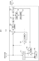
図1は実施例1に係る画像符号化装置の構成を示すブロック図である。符号化装置である半導体装置100は、ハッシュ生成部101と、参照ハッシュリスト102と、フレームモード判定部103と、イントラ予測部104と、減算器105と、直交変換部106と、量子化部107と、符号化部108と、逆量子化部109と、逆直交変換部110と、を1つの半導体基板上に備える。ハッシュ生成部101と参照ハッシュリスト102とフレームモード判定部103とを1つの半導体基板で構成し、フレームモード判定部103とイントラ予測部104と減算器105と直交変換部106と量子化部107と符号化部108と逆量子化部109と逆直交変換部110とを別の1つの半導体基板で構成してもよい。
FIG. 1 is a block diagram illustrating the configuration of the image encoding device according to the first embodiment. A
ハッシュ生成部101は符号化対象となる符号化対象フレームのハッシュ値を生成する。ハッシュ値とは、元データから一定の計算手順によって導出される、規則性のない固定長の値である。ハッシュ値は元データのデータ量によらず、常に一定の長さとなり、同じデータからは常に同じハッシュ値が得られる。本実施例ではハッシュ値は16バイトとして説明する。参照ハッシュリスト102はハッシュ生成器101によって生成されたハッシュ値を参照フレームリストとして記憶する。フレームモード判定部103はハッシュ生成器101から出力される現画像のハッシュ値と、参照ハッシュリストを比較し、フレーム符号化モードを決定するフレームモード判定部である。
The
イントラ予測部104は符号化対象ブロックの周囲の画素から予測画像を生成し、イントラ予測画像データおよびイントラ予測誤差値を生成する。減算器105は原画像データと符号化済みの画像データから生成される予測画像データの差分を算出する。直交変換部106は減算器105で計算される差分データを周波数領域に変換する。量子化部107は直交変換部106にて周波数領域に変換されるデータを量子化する。符号化部108は量子化部107にて量子化されるデータを可変長符号に変換する。逆量子化部109は量子化部107にて量子化されるデータを逆量子化する。逆直交変換部110は逆量子化部109にて逆量子化されるデータを逆直交変換する。符号化装置100の各部はハードウェア回路で構成されるが、CPUがメモリからプログラムを読み出して実行するソフトウェアで構成されてもよい。
The
図2は図1の符号化装置の符号化モード判定処理の流れを示すフローチャート図である。図3は図1の画像符号化装置のハッシュ生成例を示す図である。図4は図1の画像符号化装置の参照フレームリストとハッシュの関係を示す図である。図16は図1の画像符号化装置の符号化動作のイメージ図である。図17は図1の画像符号化装置の参照ハッシュリストの更新を説明するためのイメージ図である。 FIG. 2 is a flowchart showing the flow of the coding mode determination process of the coding apparatus of FIG. FIG. 3 is a diagram showing an example of hash generation of the image encoding device of FIG. FIG. 4 is a diagram showing the relationship between the reference frame list and the hash in the image encoding device of FIG. FIG. 16 is an image diagram of the encoding operation of the image encoding apparatus of FIG. FIG. 17 is an image diagram for explaining the update of the reference hash list of the image encoding device of FIG.
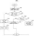
符号化モード判定処理の流れを図2のフローチャートを用いて以下説明する。
ステップS201:ハッシュ生成部101は入力画像のハッシュ値を算出する。図3に示すように、ハッシュ生成部101は入力画像(PICTURE)の輝度領域(Y)と色差領域(CbCr)とを合わせて、16バイトのハッシュ値(HASH)を算出する。図4に示すように、参照ハッシュリスト102は4つの参照フレーム(REFERENCE RFAME[0], REFERENCE RFAME[1], REFERENCE RFAME[2], REFERENCE RFAME[3])を備える。比較例1の参照画像リストは参照フレーム番号ごとに物理メモリ(フレームメモリ)のアドレスを対応付けて管理するが、本実施例ではハッシュ値を記録することで物理メモリ(フレームメモリ)を不要としている。本実施例では参照フレーム数は4フレームとして説明するが、それに限定されるものではない。
ステップS202:フレームモード判定部103は、参照ハッシュリスト102に蓄積されるハッシュ値と現在の入力画像のハッシュ値とを比較する。入力画像のハッシュ値と参照ハッシュリスト102内のハッシュ値とが一致しない場合には、ステップS203に移る。入力画像のハッシュ値と参照ハッシュリスト102内のハッシュ値とが一致する場合には、ステップS204に移る。
The flow of the coding mode determination process will be described below using the flowchart of FIG.
Step S201: The
Step S202: The frame
ステップS203:画像符号化装置100はイントラ予測に基づく符号化を行う。すなわち、イントラ予測部104は符号化対象ブロックの周囲の画素から予測画像を生成し、イントラ予測画像データおよびイントラ予測誤差値を生成する。減算器105は原画像データと符号化済みの画像データから生成される予測画像データの差分を算出する。直交変換部106は減算器105で計算される差分データを周波数領域に変換する。量子化部107は直交変換部106にて周波数領域に変換されるデータを量子化する。符号化部108は量子化部107にて量子化されるデータを可変長符号に変換し、符号化対象フレーム(入力画像)とイントラ予測画像の差分を符号化ストリームとして出力する。
ステップS204:入力画像のハッシュ値と参照ハッシュリスト102内のハッシュ値とが一致することは、過去に同一画像を受け取って符号化済みであることを意味する。すなわち全く同一の画像が参照画像リスト中に存在する。よって、画像符号化装置100は、一致した参照ハッシュ値が示す参照フレームを参照するスキップ符号化モードを行う。符号化部108で強制的にスキップ符号化モードとして符号化を行うため、イントラ予測部104、減算器105、直交変換部106、量子化部107、逆量子化部109、逆直交変換部110の処理を省略することができるので、これらの回路を停止することが可能である。
Step S203: The
Step S204: If the hash value of the input image matches the hash value in the
図16に示すように、最初のフレーム(入力画像(0))を除き、入力画像のハッシュ値と参照ハッシュリスト内の参照ハッシュ値(例えば1つ前のフレームのハッシュ値)とを用いて符号化を行う。入力画像(0)は画面内符号化のみで予測するIフレームであり、その他の入力画像の符号化は入力画像のハッシュ値と1つ前のフレームのハッシュ値との画面間予測を行うPフレームである。 As shown in FIG. 16, except for the first frame (input image (0)), the code is encoded using the hash value of the input image and the reference hash value in the reference hash list (for example, the hash value of the previous frame). To do. The input image (0) is an I frame that is predicted only by intra-screen coding, and other input images are encoded by P frames that perform inter-screen prediction between the hash value of the input image and the hash value of the previous frame. It is.
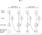
次に、スキップ符号化モードと参照ハッシュリストの更新について図17を用いて説明する。図17は入力画像(INPUT IMAGE)(0)と入力画像(1)が同一画像で、入力画像(1)と入力画像(2)で画像が変化し、入力画像(2)と入力画像(3)が同一画像の場合を示している。入力画像(1)において、ハッシュ(HASH)(h1)と参照ハッシュ(REFERENCE PICTURE [HASH])(h0)が一致するため、符号化(ENCODING)はスキップ符号化([P1])を実施する。また参照ハッシュリストはh0のまま更新しない。なお、参照ハッシュリストは同じものなので更新しない方が効率がよいが、明示的に更新してもよい。入力画像(2)において、入力画像のハッシュ(h2)と参照ハッシュ(h0)が不一致のため、符号化は通常の符号化(P2)を実施する。また参照ハッシュリストはh0をh2で更新する。入力画像(3)において、ハッシュ(h3)と参照ハッシュ(h2)が一致するため、符号化はスキップ符号化([P3])を実施する。また参照ハッシュリストはh2のまま更新しない。 Next, the skip encoding mode and the update of the reference hash list will be described with reference to FIG. In FIG. 17, the input image (INPUT IMAGE) (0) and the input image (1) are the same image, and the image changes between the input image (1) and the input image (2). ) Shows the case of the same image. In the input image (1), since the hash (HASH) (h1) matches the reference hash (REFERENCE PICTURE [HASH]) (h0), the encoding (ENCODING) performs skip encoding ([P1]). The reference hash list is not updated as h0. Since the reference hash list is the same, it is more efficient not to update it, but it may be updated explicitly. In the input image (2), since the hash (h2) of the input image and the reference hash (h0) do not match, normal encoding (P2) is performed. The reference hash list is updated with h0 by h2. Since the hash (h3) and the reference hash (h2) match in the input image (3), skip encoding ([P3]) is performed for encoding. The reference hash list is not updated as h2.
本実施例では、参照フレームリストをハッシュ値として管理することで、物理メモリ(フレームメモリ)を用いることなく、高効率なPフレームの符号化を行うことができる。また、スキップ符号化モードを選択する際には、符号化装置100内部の多くのブロックの処理を省略できるため、消費電力および動画像データ転送によるバス負荷を低減することが可能である。なお、本実施例ではハッシュ値の長さを16バイトとして説明したが、16バイトに限定されるものではなく、任意長のハッシュ値を使用することができる。またハッシュ関数としてMD5アルゴリズム等、任意のハッシュ値生成アルゴリズムをハッシュ生成部で使用することができる。
In this embodiment, by managing the reference frame list as a hash value, highly efficient P-frame encoding can be performed without using a physical memory (frame memory). Further, when the skip encoding mode is selected, the processing of many blocks in the
実施例1の主な特徴は、物理メモリ(フレームメモリ)の代わりに、ハッシュ生成器および参照ハッシュリストを設けることである。これにより、物理メモリを不要としながらも、高効率なPフレームの符号化を実現可能とした。また、参照フレームが4フレームの場合、Quad Full HD(3840×2160)サイズ、4:2:0フォーマットの場合、物理メモリの容量は3840×2160×1.5×4frame=約50Mバイト、スマ−トフォンの4:4:4のフォーマットの場合、物理メモリの容量は800×480×3frame=約1Mバイトになる。これに対し、参照ハッシュリストの容量は16×4=48バイトと、大幅にメモリ容量を削減することができる。また、物理メモリへのアクセスも発生しないことから、参照画像データ転送に伴うバス負荷を低減することが可能である。 The main feature of the first embodiment is that a hash generator and a reference hash list are provided instead of the physical memory (frame memory). This makes it possible to realize highly efficient P-frame encoding while eliminating the need for physical memory. In addition, when the reference frame is 4 frames, when the Quad Full HD (3840 × 2160) size and 4: 2: 0 format are used, the physical memory capacity is 3840 × 2160 × 1.5 × 4 frame = about 50 Mbytes, In the case of the 4: 4: 4 format of the phone, the capacity of the physical memory is 800 × 480 × 3 frame = about 1 Mbyte. On the other hand, the capacity of the reference hash list is 16 × 4 = 48 bytes, and the memory capacity can be greatly reduced. Further, since access to the physical memory does not occur, it is possible to reduce the bus load associated with reference image data transfer.
また、スキップ符号化モードが選択される場合には、符号化装置中の大半の回路を休止できるため、消費電力を大幅に低減することが可能である。スクリーンコンテンツは、一般的な自然画とはあきらかに性質が異なり、コンピュータ生成画像による静止状態が連続する傾向にあり、スマートフォンの画面等のスクリーンコンテンツを、H.264等既存の動画像符号化規格の枠組みを利用して伝送する場合に、スキップ符号化モードを適用することは有用である。 In addition, when the skip encoding mode is selected, most of the circuits in the encoding apparatus can be paused, so that power consumption can be greatly reduced. Screen content is clearly different in nature from general natural images, and there is a tendency that a still state by a computer-generated image is continuous. It is useful to apply the skip coding mode when transmitting using a framework of an existing video coding standard such as H.264.
図5は実施例2に係る画像符号化装置の構成を示すブロック図である。符号化装置である半導体装置100Aは、ハッシュ生成部101と、参照ハッシュリスト102と、フレームモード判定部103と、イントラ予測部104と、減算器105と、直交変換部106と、量子化部107と、符号化部108と、逆量子化部109と、逆直交変換部110と、インター予測部111と、予測モード判定部112と、ループフィルタ113と、フレームメモリ114とを1つの半導体基板上に備える。なお、フレームメモリ114を別の半導体基板上に備え、半導体装置100Aは複数の半導体基板で構成してもよい。また、半導体装置100Aは複数の半導体基板を1つのパッケージに封止するSiP(System in Package)で構成してもよい。
FIG. 5 is a block diagram illustrating the configuration of the image encoding device according to the second embodiment. The
インター予測部111は符号化対象フレームと、フレームメモリ114に蓄積される参照画像データの画面間予測を行い、動き検出によって生成される動きベクトルに基づき、フレームメモリから原画像データに最も近い参照画像データを読み出してインター予測画像データおよびインター予測誤差値を生成する。予測モード判定部112はインター予測部111にて生成されるインター予測誤差とイントラ予測部104にて生成されるイントラ予測誤差の比較を行い、予測誤差の小さい方を符号化モードとして選択し、その選択した符号化モードの予測誤差データを選択予測誤差として選択する。ループフィルタ113は逆直交変換部110にて逆直交変換されるデータに対してフィルタ処理を行う。フレームメモリ114はループフィルタ113にてフィルタ処理される復号画像データを参照フレームとして蓄積する。
The inter prediction unit 111 performs inter-frame prediction of the encoding target frame and reference image data stored in the
図6は図5の画像符号化装置の符号化モード判定処理の流れを示すフローチャートである。
ステップS601:ハッシュ生成部101は入力画像のハッシュ値を算出する。本実施例においても、図3に示すように、ハッシュ生成部101は入力画像(PICTURE)の輝度領域(Y)と色差領域(CbCr)とを合わせて、16バイトのハッシュ値(HASH)を算出する。図7に示すように、参照ハッシュリスト102は、実施例1と同様に、4つの参照フレーム(REFERENCE RFAME[0], REFERENCE RFAME[1], REFERENCE RFAME[2], REFERENCE RFAME[3])を備える。また、4つの参照フレームのうち1フレームには物理メモリ(フレームメモリ)を割り当てている。すなわち、参照ハッシュリスト102内の参照ハッシュ値に対応する参照画像データが1フレームのみフレームメモリ114に格納する。
FIG. 6 is a flowchart showing the flow of the coding mode determination process of the image coding apparatus of FIG.
Step S601: The
ステップS602:フレームモード判定部103は参照ハッシュリスト102に蓄積されるハッシュ値と現在の入力画像のハッシュ値とを比較する。参照リスト内のハッシュ値と現在の入力画像のハッシュ値とが一致しない場合には、ステップS603に移る。参照ハッシュリスト内のハッシュ値と現在の入力画像のハッシュ値とが一致する場合は、ステップS605に移る。
Step S602: The frame
ステップS603:イントラ予測部104は、実施例1のステップS203と同様に、イントラ予測画像データおよびイントラ予測誤差値を生成する。インター予測部111は符号化対象フレームと、フレームメモリ114に蓄積される参照画像データの画面間予測を行い、動き検出によって生成される動きベクトルに基づき、フレームメモリから原画像データに最も近い参照画像データを読み出してインター予測画像データおよびインター予測誤差値を生成する。
Step S603: The intra
ステップS604:予測モード判定部112はインター予測誤差とイントラ予測誤差の比較を行い、予測誤差の小さい方を符号化モードとして選択する。すなわち、予測モード判定部112は符号化コストの小さい方を符号化モードとして選択し、画像符号化装置100Aは選択した符号化モードに基づいて符号化を行う。すなわち、画像符号化装置100Aはイントラ予測およびインター予測に基づいて符号化を行う。イントラ予測およびインター予測に基づく符号化は実施例1のステップS203と同様である。
Step S604: The prediction
ステップS605:実施例1のステップS204と同様にスキップ符号化を行う。イントラ予測部104、減算器105、直交変換部106、量子化部107、逆量子化部109、逆直交変換部110、インター予測部111、予測モード判定部112、ループフィルタ113の処理を省略することができるので、これらの回路を停止することが可能である。
Step S605: Skip encoding is performed in the same manner as step S204 in the first embodiment. The processing of the
なお、本実施例ではハッシュ参照フレーム4面のうち、物理参照フレーム1面として説明したが、それに限定されるものではなく、任意の物理参照フレーム数、ハッシュ参照フレーム数を割り当てることができる。 In the present embodiment, the physical reference frame is one of the four hash reference frames. However, the present invention is not limited to this, and an arbitrary number of physical reference frames and the number of hash reference frames can be assigned.
実施例2の主な特徴は、実施例1に加えて物理参照フレームを追加したことで、ハッシュ値と、物理参照フレームの双方を予測に使えるようにしたことである。これにより、同一画像の入力が多い場合は、ハッシュ値が一致し、符号化処理を大幅に省略することができ、また同一画像入力が少ない場合には、通常のイントラ予測およびインター予測を行うことで、画質劣化を抑制することができる。 The main feature of the second embodiment is that, by adding a physical reference frame in addition to the first embodiment, both a hash value and a physical reference frame can be used for prediction. As a result, when the same image input is large, the hash values match and the encoding process can be largely omitted. When the same image input is small, normal intra prediction and inter prediction are performed. Thus, image quality deterioration can be suppressed.
<変形例>
図8は変形例1に係る画像符号化装置のハッシュ生成例を示す図である。図9は変形例1に係る画像符号化装置の符号化モード判定処理の流れを示すフローチャートである。
ステップS901:ハッシュ生成部101は入力画像のハッシュ値を輝度と色差別に算出する。図8に示すように、輝度領域(Y)と色差領域(CbCr)に分けてハッシュ値(HASH)を生成する。変形例1においても、図7に示すように、参照ハッシュリスト102は4つの参照フレーム(REFERENCE RFAME[0], REFERENCE RFAME[1], REFERENCE RFAME[2], REFERENCE RFAME[3])を備える。
<Modification>
FIG. 8 is a diagram illustrating a hash generation example of the image encoding device according to the first modification. FIG. 9 is a flowchart illustrating the flow of the encoding mode determination process of the image encoding device according to the first modification.
Step S901: The
ステップS902:フレームモード判定部103は参照ハッシュリスト102に蓄積される輝度のハッシュ値と現在の入力画像の輝度のハッシュ値とを比較する。参照ハッシュリスト102内の輝度ハッシュと現在の入力画像の輝度のハッシュ値とが一致しない場合には、ステップS903に移る。参照ハッシュリスト102内の輝度のハッシュ値と現在の入力画像の輝度のハッシュ値とが一致する場合は、ステップS905に移る。
Step S902: The frame
ステップS903:変形例1に係る画像符号化装置は、実施例2のステップS603と同様にイントラ予測およびインター予測を行う。 Step S903: The image coding apparatus according to the first modification performs intra prediction and inter prediction similarly to step S603 in the second embodiment.
ステップS904:予測モード判定部112は、実施例2のステップS604と同様に符号化コストの小さい方を符号化モードとして選択する。
Step S904: The prediction
ステップS905:フレームモード判定部103は参照ハッシュリスト102に蓄積された色差のハッシュ値と現在の入力画像の色差のハッシュ値とを比較する。参照ハッシュリスト102に蓄積される色差のハッシュ値と現在の入力画像の色差のハッシュ値とが一致する場合にはステップS907に移る。参照ハッシュリスト102に蓄積される色差のハッシュ値と現在の入力画像の色差のハッシュ値とが一致しない場合には、ステップS906に移る。
Step S905: The frame
ステップS906:輝度の符号化を省略することができることになるため、色差のインター予測の符号化を行い、輝度の参照画像データのフレームメモリ114からの読み出しを抑制し、色差のみ差分を符号化する。
Step S906: Since the luminance encoding can be omitted, the color difference inter prediction encoding is performed, the reading of the luminance reference image data from the
ステップS907:変形例1に係る画像符号化装置は、実施例2のステップS605と同様にスキップ符号化を行う。 Step S907: The image coding apparatus according to the first modification performs skip coding as in step S605 in the second embodiment.
変形例1の主な特徴は、実施例2に加えてハッシュ値の生成単位を輝度と色差で分けることで、輝度のみハッシュ値が一致するケースを効率よく扱えるようにすることである。これにより、輝度のみハッシュ値が一致する場合には、フレームメモリ114内の輝度の参照画像データのアクセスを抑制し、色差の参照画像データのアクセスのみとすることが可能である。フレーム内画素値が完全一致しない場合においても符号化処理の一部分を省略することが可能となる。なお、変形例1ではハッシュ値の生成単位を輝度と色差で分割するが、それに限定されるものではない。
The main feature of the first modification is that, in addition to the second embodiment, the hash value generation unit is divided by the luminance and the color difference so that the case where the hash values match only the luminance can be efficiently handled. As a result, when the hash values of only the luminance match, it is possible to suppress the access of the luminance reference image data in the
図10は変形例2に係る画像符号化装置のハッシュ生成例を示す図である。変形例2に係る画像符号化装置のハッシュ生成器101は入力画像のハッシュ値をH.264等の符号化単位であるスライス単位(SLICE[0], SLICE[1])で生成し、管理する。任意の物理参照フレーム、ハッシュ参照フレーム数を割り当てることができる。変形例2は、変形例1と同様にフレームメモリ内の参照データのアクセス量を削減することができ、フレーム内画素値が完全一致しない場合においても符号化処理の一部分を省略することが可能となる。
FIG. 10 is a diagram illustrating a hash generation example of the image encoding device according to the second modification. The
図11は変形例3に係る画像符号化装置のハッシュ生成例を示す図である。変形例2に係る画像符号化装置のハッシュ生成器101は、入力画像の注目領域(INTEREST)と非注目領域(NON-INTEREST)とで別々のハッシュ値を生成し、管理する。変形例3は、変形例1と同様にフレームメモリ内の参照データのアクセス量を削減することができ、フレーム内画素値が完全一致しない場合においても符号化処理の一部分を省略することが可能となる。
FIG. 11 is a diagram illustrating a hash generation example of the image encoding device according to the third modification. The
図12は実施例3に係る画像符号化装置の構成を示すブロック図である。符号化装置である半導体装置100Bは、ハッシュ生成部101と、参照ハッシュリスト102と、フレームモード判定部103と、イントラ予測部104と、減算器105と、直交変換部106と、量子化部107と、符号化部108と、逆量子化部109と、逆直交変換部110と、ハッシュフィルタ115と、を1つの半導体基板上に備える。ハッシュフィルタ115は符号化対象フレームを平滑化し、同一ハッシュ生成確率を向上させるためのものである。実施例3は実施例1のハッシュ生成部101の前にハッシュフィルタ115を設けたものであるが、変形例のハッシュ生成部101の前にハッシュフィルタ115を設けてもよい。
FIG. 12 is a block diagram illustrating the configuration of the image encoding device according to the third embodiment. The semiconductor device 100B, which is an encoding device, includes a
ハッシュ値の特性上、ハッシュ関数への入力が1ビットでも異なれば出力されるハッシュ値が異なってしまう。例えば入力画像に微小なノイズが乗る場合に、異なるハッシュが生成されてしまい、完全一致するハッシュを得ることが困難になる。ハッシュフィルタ115において、入力画像を平滑化し、微小なノイズを除去することで、生成されるハッシュ値が一致する確率を向上させることができる。ハッシュフィルタ115は、例えば、下位ビットを無視するビットマスクでもよいし、量子化でもよいし、ローパルフィルタやノイズ除去フィルタでもよい。
Due to the characteristics of the hash value, if the input to the hash function is different even by 1 bit, the output hash value will be different. For example, when a minute noise is applied to the input image, different hashes are generated, and it is difficult to obtain a completely matching hash. By smoothing the input image and removing minute noises in the
実施例3の主な特徴はハッシュフィルタを設けることで、ハッシュ値の生成を制御できるようにしたことである。これにより、入力画像に微小なノイズが乗った際であっても、ノイズによるハッシュ値の不一致を回避でき、符号化効率を向上させることが可能である。 The main feature of the third embodiment is that a hash value can be controlled by providing a hash filter. Thereby, even when a minute noise is applied to the input image, it is possible to avoid the mismatch of the hash values due to the noise and to improve the encoding efficiency.
以上、本発明者によってなされた発明を実施形態、実施例および変形例に基づき具体的に説明したが、本発明は、上記実施形態、実施例および変形例に限定されるものではなく、種々変更可能であることはいうまでもない。 As mentioned above, the invention made by the present inventor has been specifically described based on the embodiments, examples, and modifications. However, the present invention is not limited to the above-described embodiments, examples, and modifications, and various modifications can be made. It goes without saying that it is possible.
100・・・半導体装置
101・・・ハッシュ生成部
102・・・ハッシュ参照リスト
103・・・フレームモード判定部
104・・・イントラ予測部
105・・・減算器
106・・・直交変換部
107・・・量子化部
108・・・符号化部
109・・・逆量子化部
110・・・逆直交変換部
111・・・インター予測部
112・・・予測モード判定部
113・・・ループフィルタ
114・・・フレームメモリ
115・・・ハッシュフィルタ
DESCRIPTION OF
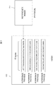
Claims (15)
符号化対象フレームのハッシュ値を生成するハッシュ生成器;
前記ハッシュ生成器で生成するハッシュ値を記録する参照ハッシュリスト;
前記ハッシュ生成器で生成するハッシュ値と前記参照ハッシュリスト内のハッシュ値とを比較するフレームモード判定部;
前記符号化対象フレームを画面内予測するイントラ予測部、
ここで、前記符号化対象フレームのハッシュ値と前記参照ハッシュリスト中のハッシュ値が一致する場合には、前記イントラ予測部は符号化処理を省略し、前記参照ハッシュリスト中のハッシュ値に対応する符号化情報を出力する。 The semiconductor device includes:
A hash generator for generating a hash value of the encoding target frame;
A reference hash list for recording a hash value generated by the hash generator;
A frame mode determination unit that compares a hash value generated by the hash generator with a hash value in the reference hash list;
An intra prediction unit that predicts the encoding target frame within a screen;
Here, when the hash value of the encoding target frame matches the hash value in the reference hash list, the intra prediction unit omits the encoding process and corresponds to the hash value in the reference hash list. Output encoded information.
前記符号化対象フレームのハッシュ値と前記参照ハッシュリスト中のハッシュ値が一致しない場合には、前記イントラ予測部は画面内予測を行う。 The semiconductor device according to claim 1.
When the hash value of the encoding target frame does not match the hash value in the reference hash list, the intra prediction unit performs intra prediction.
インター予測部;
物理参照フレームを格納するフレームメモリ、
ここで、前記符号化対象フレームのハッシュ値と前記参照ハッシュリスト中のハッシュ値が一致しない場合には、前記インター予測部は前記物理参照フレームとの画面間予測を行う。 The semiconductor device of claim 2, further comprising:
Inter prediction unit;
Frame memory to store physical reference frames,
Here, when the hash value of the encoding target frame does not match the hash value in the reference hash list, the inter prediction unit performs inter-screen prediction with the physical reference frame.
前記インター予測部にて生成されたインター予測誤差と前記イントラ予測部にて生成されたイントラ予測誤差の比較を行い、予測誤差の小さい方を符号化モードとして選択し、その選択したモードの予測誤差データを選択予測誤差として選択する予測モード判定部。 The semiconductor device of claim 3, further comprising:
The inter prediction error generated by the inter prediction unit and the intra prediction error generated by the intra prediction unit are compared, the smaller prediction error is selected as the encoding mode, and the prediction error of the selected mode is selected. A prediction mode determination unit that selects data as a selection prediction error.
前記ハッシュ生成器は、ハッシュ値の生成単位を、輝度・色差別、スライスの符号化単位別、注目領域・非注目領域別のいずれかに分けて、ハッシュ値を生成する。 The semiconductor device according to any one of claims 1 to 4,
The hash generator divides a hash value generation unit into one of luminance / color discrimination, slice encoding unit, and attention area / non-attention area to generate a hash value.
前記ハッシュ生成器の前に前記符号化対象フレームを平準化するハッシュフィルタ。 5. The semiconductor device according to claim 1, further comprising:
A hash filter for leveling the encoding target frame before the hash generator.
前記ハッシュ生成器と前記参照ハッシュリストと前記フレームモード判定部と前記イントラ予測部とを1つの半導体基板上に構成する。 The semiconductor device according to claim 1 or 2,
The hash generator, the reference hash list, the frame mode determination unit, and the intra prediction unit are configured on one semiconductor substrate.
前記ハッシュ生成器と前記参照ハッシュリストと前記フレームモード判定部と前記イントラ予測部と前記インター予測部とを1つの半導体基板上に構成し、
前記物理参照メモリを前記半導体基板とは異なる半導体基板上に構成する。 The semiconductor device according to claim 3 or 4,
The hash generator, the reference hash list, the frame mode determination unit, the intra prediction unit, and the inter prediction unit are configured on one semiconductor substrate,
The physical reference memory is configured on a semiconductor substrate different from the semiconductor substrate.
前記符号化対象フレームの画像データと符号化済みの画像データから生成される予測画像データの差分を算出する減算器;
前記減算器で計算される差分データを周波数領域に変換する直交変換部;
前記直交変換部で周波数領域に変換されるデータを量子化する量子化部;
前記量子化部で量子化されるデータを可変長符号に変換する符号化部;
前記量子化部で量子化されるデータを逆量子化する逆量子化部;
前記逆量子化部で逆量子化されるデータを逆直交変換する逆直交変換部、
ここで、前記符号化対象フレームのハッシュ値と前記参照ハッシュリスト中のハッシュ値が一致する場合には、前記減算器、前記直交変換部、前記量子化部、前記逆量子化部および前記逆直交変換部の処理を停止する。 The semiconductor device of claim 1, further comprising:
A subtractor for calculating a difference between image data of the encoding target frame and predicted image data generated from the encoded image data;
An orthogonal transform unit for transforming difference data calculated by the subtracter into a frequency domain;
A quantization unit that quantizes data to be transformed into the frequency domain by the orthogonal transform unit;
An encoding unit that converts data quantized by the quantization unit into a variable-length code;
An inverse quantization unit that inversely quantizes data quantized by the quantization unit;
An inverse orthogonal transform unit that performs inverse orthogonal transform on data that is inversely quantized by the inverse quantization unit;
Here, when the hash value of the encoding target frame matches the hash value in the reference hash list, the subtracter, the orthogonal transform unit, the quantization unit, the inverse quantization unit, and the inverse orthogonal Stop the processing of the conversion unit.
(a)符号化対象フレームのハッシュ値を生成するステップ;
(b)前記ハッシュ値を参照ハッシュリストに記録するステップ;
(c)前記ステップ(a)で生成したハッシュ値と前記ステップ(b)で記憶したハッシュ値とを比較するステップ;
(d)前記ステップ(c)でハッシュ値が一致しない場合、前記符号化対象フレームを画面内予測するステップ:
(e)前記ステップ(c)でハッシュ値が一致する場合、符号化処理を省略し、前記参照ハッシュリスト中のハッシュ値に対応する符号化情報を出力するステップ。 Image coding methods include:
(A) generating a hash value of the encoding target frame;
(B) recording the hash value in a reference hash list;
(C) comparing the hash value generated in step (a) with the hash value stored in step (b);
(D) If the hash values do not match in step (c), the step of intra-predicting the encoding target frame:
(E) A step of omitting encoding processing and outputting encoded information corresponding to the hash value in the reference hash list when the hash values match in the step (c).
(f)前記ステップ(c)でハッシュ値が一致しない場合、前記符号化対象フレームを画面間予測するステップ。 The image encoding method of claim 10, further comprising:
(F) A step of inter-predicting the encoding target frame when the hash values do not match in the step (c).
(g)前記ステップ(f)で生成されたインター予測誤差と前記ステップ(d)で生成されたイントラ予測誤差の比較を行い、予測誤差の小さい方を符号化モードとして選択し、その選択したモードの予測誤差データを選択予測誤差として選択するステップ。 The image encoding method of claim 11, further comprising:
(G) The inter prediction error generated in the step (f) and the intra prediction error generated in the step (d) are compared, the smaller prediction error is selected as the encoding mode, and the selected mode Selecting the prediction error data of as a selected prediction error.
前記ステップ(a)はハッシュ値の生成単位を、輝度・色差別、スライスの符号化単位別、注目領域・非注目領域別のいずれかに分けて、ハッシュを生成する。 The image encoding method according to any one of claims 10 to 12,
In the step (a), the hash value generation unit is divided into luminance / color discrimination, slice encoding unit, attention area / non-attention area, and a hash is generated.
(h)前記ステップ(a)の前に前記符号化対象フレームを平準化するステップ。 The image encoding method according to any one of claims 10 to 12, further comprising:
(H) A step of leveling the encoding target frame before the step (a).
前記ステップ(e)は、減算処理、直交変換処理、量子化処理、逆量子化処理および逆直交変換処理を停止する。 The semiconductor device according to claim 10.
The step (e) stops the subtraction process, orthogonal transform process, quantization process, inverse quantization process, and inverse orthogonal transform process.
Priority Applications (5)
| Application Number | Priority Date | Filing Date | Title |
|---|---|---|---|
| JP2015189671A JP2017069617A (en) | 2015-09-28 | 2015-09-28 | Semiconductor device and image encoding method |
| KR1020160106259A KR20170037815A (en) | 2015-09-28 | 2016-08-22 | Semiconductor device and image encoding method |
| CN201610822800.0A CN106559675A (en) | 2015-09-28 | 2016-09-13 | Semiconductor device |
| US15/266,528 US10021397B2 (en) | 2015-09-28 | 2016-09-15 | Semiconductor device |
| US16/001,559 US20180288418A1 (en) | 2015-09-28 | 2018-06-06 | Semiconductor device |
Applications Claiming Priority (1)
| Application Number | Priority Date | Filing Date | Title |
|---|---|---|---|
| JP2015189671A JP2017069617A (en) | 2015-09-28 | 2015-09-28 | Semiconductor device and image encoding method |
Publications (2)
| Publication Number | Publication Date |
|---|---|
| JP2017069617A true JP2017069617A (en) | 2017-04-06 |
| JP2017069617A5 JP2017069617A5 (en) | 2018-07-05 |
Family
ID=58406028
Family Applications (1)
| Application Number | Title | Priority Date | Filing Date |
|---|---|---|---|
| JP2015189671A Pending JP2017069617A (en) | 2015-09-28 | 2015-09-28 | Semiconductor device and image encoding method |
Country Status (4)
| Country | Link |
|---|---|
| US (2) | US10021397B2 (en) |
| JP (1) | JP2017069617A (en) |
| KR (1) | KR20170037815A (en) |
| CN (1) | CN106559675A (en) |
Families Citing this family (2)
| Publication number | Priority date | Publication date | Assignee | Title |
|---|---|---|---|---|
| JP2017069617A (en) * | 2015-09-28 | 2017-04-06 | ルネサスエレクトロニクス株式会社 | Semiconductor device and image encoding method |
| CN107396112B (en) * | 2017-08-01 | 2021-03-09 | 深信服科技股份有限公司 | Encoding method and device, computer device and readable storage medium |
Citations (3)
| Publication number | Priority date | Publication date | Assignee | Title |
|---|---|---|---|---|
| JPH0723394A (en) * | 1993-06-18 | 1995-01-24 | Sharp Corp | Image compressing device |
| US20130266073A1 (en) * | 2012-04-08 | 2013-10-10 | Broadcom Corporation | Power saving techniques for wireless delivery of video |
| US20140003494A1 (en) * | 2012-01-05 | 2014-01-02 | Yaniv Frishman | Device, system and method of video encoding |
Family Cites Families (19)
| Publication number | Priority date | Publication date | Assignee | Title |
|---|---|---|---|---|
| CN100511329C (en) * | 2000-01-21 | 2009-07-08 | 索尼公司 | Data processing apparatus and data processing method |
| GB2446199A (en) * | 2006-12-01 | 2008-08-06 | David Irvine | Secure, decentralised and anonymous peer-to-peer network |
| JP2009200763A (en) * | 2008-02-21 | 2009-09-03 | Ricoh Co Ltd | Electronic document tracing apparatus and method, program, and recording medium |
| JP5294767B2 (en) * | 2008-09-16 | 2013-09-18 | キヤノン株式会社 | Movie playback device, movie playback method, program, and recording medium |
| US8788830B2 (en) * | 2008-10-02 | 2014-07-22 | Ricoh Co., Ltd. | Method and apparatus for logging based identification |
| KR101072277B1 (en) * | 2009-08-31 | 2011-10-11 | 주식회사 아나스타시스 | Apparatus and method for guaranteeing data integrity in real time, and black box system using thereof |
| US8600371B2 (en) * | 2009-10-18 | 2013-12-03 | Locus Location Systems Llc | Method and system for diagnosing radio performance during functional over-the-air operation |
| US8428045B2 (en) * | 2010-03-16 | 2013-04-23 | Harman International Industries, Incorporated | Media clock recovery |
| JP5387520B2 (en) * | 2010-06-25 | 2014-01-15 | ソニー株式会社 | Information processing apparatus and information processing method |
| CN103416064A (en) * | 2011-03-18 | 2013-11-27 | 索尼公司 | Image-processing device, image-processing method, and program |
| TW201315246A (en) * | 2011-09-27 | 2013-04-01 | Sony Corp | Image processing device and method |
| US20130268621A1 (en) * | 2012-04-08 | 2013-10-10 | Broadcom Corporation | Transmission of video utilizing static content information from video source |
| US9491461B2 (en) * | 2012-09-27 | 2016-11-08 | Qualcomm Incorporated | Scalable extensions to HEVC and temporal motion vector prediction |
| JP2014082639A (en) * | 2012-10-16 | 2014-05-08 | Canon Inc | Image encoder and method of the same |
| JP2015002371A (en) | 2013-06-13 | 2015-01-05 | キヤノン株式会社 | Image coding device, image coding method and program |
| CN105556971B (en) * | 2014-03-04 | 2019-07-30 | 微软技术许可有限责任公司 | It stirs for the block in intra block duplication prediction and determines with the coder side of dancing mode |
| US9715559B2 (en) * | 2014-03-17 | 2017-07-25 | Qualcomm Incorporated | Hash-based encoder search for intra block copy |
| JP2017069617A (en) * | 2015-09-28 | 2017-04-06 | ルネサスエレクトロニクス株式会社 | Semiconductor device and image encoding method |
| US11455621B2 (en) * | 2015-11-25 | 2022-09-27 | Idemia Identity & Security USA LLC | Device-associated token identity |
-
2015
- 2015-09-28 JP JP2015189671A patent/JP2017069617A/en active Pending
-
2016
- 2016-08-22 KR KR1020160106259A patent/KR20170037815A/en unknown
- 2016-09-13 CN CN201610822800.0A patent/CN106559675A/en active Pending
- 2016-09-15 US US15/266,528 patent/US10021397B2/en active Active
-
2018
- 2018-06-06 US US16/001,559 patent/US20180288418A1/en not_active Abandoned
Patent Citations (3)
| Publication number | Priority date | Publication date | Assignee | Title |
|---|---|---|---|---|
| JPH0723394A (en) * | 1993-06-18 | 1995-01-24 | Sharp Corp | Image compressing device |
| US20140003494A1 (en) * | 2012-01-05 | 2014-01-02 | Yaniv Frishman | Device, system and method of video encoding |
| US20130266073A1 (en) * | 2012-04-08 | 2013-10-10 | Broadcom Corporation | Power saving techniques for wireless delivery of video |
Also Published As
| Publication number | Publication date |
|---|---|
| US20180288418A1 (en) | 2018-10-04 |
| CN106559675A (en) | 2017-04-05 |
| US20170094280A1 (en) | 2017-03-30 |
| KR20170037815A (en) | 2017-04-05 |
| US10021397B2 (en) | 2018-07-10 |
Similar Documents
| Publication | Publication Date | Title |
|---|---|---|
| CN110024398B (en) | Local hash-based motion estimation for screen teleprocessing scenes | |
| TWI759389B (en) | Low-complexity sign prediction for video coding | |
| JP7303322B2 (en) | Encoders, decoders and corresponding methods for intra prediction | |
| WO2019242491A1 (en) | Video encoding and decoding method and device, computer device, and storage medium | |
| TW202025752A (en) | History-based motion vector prediction for affine mode | |
| TW202044839A (en) | Intra block copy merging data syntax for video coding | |
| TW202041024A (en) | Signalling for merge mode with motion vector differences in video coding | |
| TW202038611A (en) | Triangle motion information for video coding | |
| BR112017004490B1 (en) | METHOD FOR CONSTRUCTING A HASH TABLE FOR HASH-BASED BLOCK MATCHING, COMPUTING DEVICE AND COMPUTER READABLE STORAGE MEDIA | |
| JPWO2010004939A1 (en) | Image encoding device, image decoding device, image encoding method, and image decoding method | |
| TW201820875A (en) | Video decoding apparatus, video encoding method and apparatus, and computer-readable storage medium | |
| BR112014010839B1 (en) | Image encoding and decoding process, encoding and decoding device and corresponding computer readable media | |
| US11496754B2 (en) | Video encoder, video decoder, and corresponding method of predicting random access pictures | |
| US20160050431A1 (en) | Method and system for organizing pixel information in memory | |
| TW202002654A (en) | Coefficient coding with grouped bypass bins | |
| JP2017069617A (en) | Semiconductor device and image encoding method | |
| KR20130006578A (en) | Residual coding in compliance with a video standard using non-standardized vector quantization coder | |
| JP2009260494A (en) | Image coding apparatus and its control method | |
| TW202046732A (en) | Method and apparatus of video coding | |
| JP2020058075A (en) | Moving image prediction encoding device, moving image prediction decoding device, moving image prediction encoding method, moving image prediction decoding method, and recording medium | |
| US10057583B2 (en) | Encoding method of image encoding device | |
| TWI834269B (en) | Video processing method and apparatus thereof | |
| JP2003179929A (en) | Image decoding apparatus | |
| JP4301495B2 (en) | Video compression encoding device | |
| JP6646125B2 (en) | Video prediction decoding method and video prediction decoding device |
Legal Events
| Date | Code | Title | Description |
|---|---|---|---|
| A521 | Request for written amendment filed |
Free format text: JAPANESE INTERMEDIATE CODE: A523 Effective date: 20160203 |
|
| A521 | Request for written amendment filed |
Free format text: JAPANESE INTERMEDIATE CODE: A523 Effective date: 20180524 |
|
| A621 | Written request for application examination |
Free format text: JAPANESE INTERMEDIATE CODE: A621 Effective date: 20180524 |
|
| A131 | Notification of reasons for refusal |
Free format text: JAPANESE INTERMEDIATE CODE: A131 Effective date: 20190226 |
|
| A977 | Report on retrieval |
Free format text: JAPANESE INTERMEDIATE CODE: A971007 Effective date: 20190228 |
|
| A521 | Request for written amendment filed |
Free format text: JAPANESE INTERMEDIATE CODE: A523 Effective date: 20190410 |
|
| A131 | Notification of reasons for refusal |
Free format text: JAPANESE INTERMEDIATE CODE: A131 Effective date: 20190423 |
|
| A521 | Request for written amendment filed |
Free format text: JAPANESE INTERMEDIATE CODE: A523 Effective date: 20190619 |
|
| A131 | Notification of reasons for refusal |
Free format text: JAPANESE INTERMEDIATE CODE: A131 Effective date: 20190903 |
|
| A02 | Decision of refusal |
Free format text: JAPANESE INTERMEDIATE CODE: A02 Effective date: 20200303 |