JP2017068614A - Analysis program, analysis apparatus, and analysis method - Google Patents
Analysis program, analysis apparatus, and analysis method Download PDFInfo
- Publication number
- JP2017068614A JP2017068614A JP2015193728A JP2015193728A JP2017068614A JP 2017068614 A JP2017068614 A JP 2017068614A JP 2015193728 A JP2015193728 A JP 2015193728A JP 2015193728 A JP2015193728 A JP 2015193728A JP 2017068614 A JP2017068614 A JP 2017068614A
- Authority
- JP
- Japan
- Prior art keywords
- component
- components
- information
- log
- code
- Prior art date
- Legal status (The legal status is an assumption and is not a legal conclusion. Google has not performed a legal analysis and makes no representation as to the accuracy of the status listed.)
- Granted
Links
Images


Classifications
-
- G—PHYSICS
- G06—COMPUTING OR CALCULATING; COUNTING
- G06F—ELECTRIC DIGITAL DATA PROCESSING
- G06F21/00—Security arrangements for protecting computers, components thereof, programs or data against unauthorised activity
- G06F21/50—Monitoring users, programs or devices to maintain the integrity of platforms, e.g. of processors, firmware or operating systems
- G06F21/55—Detecting local intrusion or implementing counter-measures
- G06F21/56—Computer malware detection or handling, e.g. anti-virus arrangements
- G06F21/562—Static detection
- G06F21/563—Static detection by source code analysis
-
- G—PHYSICS
- G06—COMPUTING OR CALCULATING; COUNTING
- G06F—ELECTRIC DIGITAL DATA PROCESSING
- G06F16/00—Information retrieval; Database structures therefor; File system structures therefor
- G06F16/90—Details of database functions independent of the retrieved data types
- G06F16/903—Querying
- G06F16/90335—Query processing
-
- H—ELECTRICITY
- H04—ELECTRIC COMMUNICATION TECHNIQUE
- H04L—TRANSMISSION OF DIGITAL INFORMATION, e.g. TELEGRAPHIC COMMUNICATION
- H04L41/00—Arrangements for maintenance, administration or management of data switching networks, e.g. of packet switching networks
- H04L41/06—Management of faults, events, alarms or notifications
- H04L41/069—Management of faults, events, alarms or notifications using logs of notifications; Post-processing of notifications
-
- H—ELECTRICITY
- H04—ELECTRIC COMMUNICATION TECHNIQUE
- H04L—TRANSMISSION OF DIGITAL INFORMATION, e.g. TELEGRAPHIC COMMUNICATION
- H04L67/00—Network arrangements or protocols for supporting network services or applications
- H04L67/01—Protocols
- H04L67/10—Protocols in which an application is distributed across nodes in the network
Landscapes
- Engineering & Computer Science (AREA)
- Computer Security & Cryptography (AREA)
- Theoretical Computer Science (AREA)
- General Engineering & Computer Science (AREA)
- Software Systems (AREA)
- Computer Hardware Design (AREA)
- Computer Networks & Wireless Communication (AREA)
- Signal Processing (AREA)
- General Physics & Mathematics (AREA)
- Physics & Mathematics (AREA)
- Health & Medical Sciences (AREA)
- Virology (AREA)
- General Health & Medical Sciences (AREA)
- Databases & Information Systems (AREA)
- Computational Linguistics (AREA)
- Data Mining & Analysis (AREA)
- Debugging And Monitoring (AREA)
- Environmental & Geological Engineering (AREA)
- Stored Programmes (AREA)
Abstract
【課題】プログラムの分析の処理時間を短縮する。【解決手段】分析装置10の分析部12は、第1コンポーネントを記載した第1コード13と、第2コンポーネントを記載した第2コード14とを比較し、差分コンポーネント14aを抽出する。分析部12は、第2コンポーネントが配備された実行装置20に対して複数のリクエストを送信して、差分コンポーネント14aの実行状況を示す第1ログ情報15を取得し、差分コンポーネント14aの実行に関連する関連リクエストを特定する。分析部12は、特定した関連リクエストを実行装置20に対して送信して、第2コンポーネントの実行状況を示す第2ログ情報16を取得する。分析部12は、第2ログ情報16に基づいて、第2コンポーネントのうち、関連リクエストに応じて実行される第2コンポーネントに関するパス情報17を生成し、記憶部11に格納する。【選択図】図1The processing time for analyzing a program is shortened. An analysis unit 12 of an analysis apparatus 10 compares a first code 13 describing a first component with a second code 14 describing a second component, and extracts a difference component 14a. The analysis unit 12 transmits a plurality of requests to the execution device 20 in which the second component is deployed, acquires the first log information 15 indicating the execution status of the difference component 14a, and relates to the execution of the difference component 14a. Identify related requests. The analysis unit 12 transmits the identified related request to the execution device 20, and acquires the second log information 16 indicating the execution status of the second component. Based on the second log information 16, the analysis unit 12 generates path information 17 related to the second component executed in response to the related request among the second components, and stores the path information 17 in the storage unit 11. [Selection] Figure 1
Description
本発明は分析プログラム、分析装置および分析方法に関する。 The present invention relates to an analysis program, an analysis apparatus, and an analysis method.
アプリケーションやネットワークサービスなどは、運用時にシステムのスローダウンなどの不具合が発生することがある。不具合が発生したとき、システムの管理者は、遅延個所や異常個所を発見するための分析を行う。例えば、遅延個所の分析では、対象のアプリケーションやネットワークサービスの処理を実行するプログラムに多数の監視箇所を設け、監視箇所において大量のログを採取する。管理者は、監視箇所で採取したログに付されたタイムスタンプによって、監視箇所間の処理に要した時間を検出し、遅延個所を特定する。同様に、採取したログに基づき、例えば、想定外の実行状況にある箇所を異常個所として特定することができる。しかしながら、遅延個所などの絞り込みや特定にあたっては、多数の監視箇所で大量のログを採取することが好ましい。このため、運用状況にあるシステムに多大な実行オーバーヘッドとネットワーク負荷が発生するおそれがある。 Applications and network services may experience problems such as system slowdown during operation. When a problem occurs, the system administrator performs an analysis to find a delayed part or an abnormal part. For example, in the analysis of the delay location, a large number of monitoring locations are provided in the program that executes the processing of the target application or network service, and a large amount of logs are collected at the monitoring location. The administrator detects the time required for processing between the monitoring locations by the time stamp attached to the log collected at the monitoring location, and identifies the delay location. Similarly, based on the collected logs, for example, a part in an unexpected execution situation can be identified as an abnormal part. However, it is preferable to collect a large number of logs at a large number of monitoring locations when narrowing down or identifying delay locations. For this reason, there is a possibility that enormous execution overhead and network load may occur in the system in the operating state.
例えば、運用前にプログラムを分析し、アプリケーションがリクエストを受け付けたときに、アプリケーションが利用するコンポーネントを示すパス情報を生成する分析装置がある。ここで、パスは、リクエストに応じたアプリケーションが利用するコンポーネントの集合を指す。事前分析では、分析装置は、多数の監視箇所で詳細なログを採取する設定を行い、システムなどで想定される全リクエストパターンを送信して詳細なログ情報を取得する。分析装置は、取得した詳細なログ情報に基づいてパス情報を生成し、アプリケーションの運用時の不具合箇所の検出に利用する。 For example, there is an analysis device that analyzes a program before operation and generates path information indicating a component used by an application when the application receives a request. Here, the path indicates a set of components used by the application in response to the request. In the pre-analysis, the analysis apparatus performs settings for collecting detailed logs at a large number of monitoring locations, and transmits all request patterns assumed by the system or the like to acquire detailed log information. The analysis device generates path information based on the acquired detailed log information and uses it to detect a defective part during operation of the application.
しかしながら、システムテストなどで想定される全てのリクエストパターンを用いてプログラムを実行し、その詳細なログ情報を採取するには多大な時間を要する。
分析の対象のプログラムには、既存のプログラムの一部分を変更しただけのものがある。しかしながら、一部の変更であっても変更がパスに及ぼす影響をソースコードの分析といった静的な分析から検出することは容易ではない。コンポーネントの呼び出しが動的に決定されるプログラムでは、実際にプログラムを実行しなければコンポーネントの呼び出し関係を検出することができない。変更されたコンポーネントが、既存のコンポーネントを利用する場合もあるため、プログラムの分析にあたっては、想定され得る全リクエストパターンを用いてプログラムを実行し、詳細なログを採取する。よって、既存のプログラムからの変更量がわずかなプログラムであっても、分析の処理時間を短縮することが容易ではなかった。
However, it takes a lot of time to execute a program using all request patterns assumed in a system test and collect detailed log information.
Some of the programs to be analyzed are modified from a part of an existing program. However, even for some changes, it is not easy to detect the effect of the change on the path from static analysis such as source code analysis. In a program in which component invocation is dynamically determined, the component invocation relationship cannot be detected unless the program is actually executed. Since the changed component may use an existing component, in analyzing the program, the program is executed using all possible request patterns and a detailed log is collected. Therefore, it is not easy to shorten the analysis processing time even if the amount of change from the existing program is small.
1つの側面では、本発明は、プログラムの分析の処理時間を短縮できる分析プログラム、分析装置および分析方法を提供することを目的とする。 In one aspect, an object of the present invention is to provide an analysis program, an analysis apparatus, and an analysis method that can shorten the processing time of program analysis.
1つの態様では、コンピュータに以下の処理を実行させる分析プログラムが提供される。複数の第1コンポーネントを記載したコードであって複数のリクエストそれぞれの受信に応じて複数の第1コンポーネントの少なくとも一部が実行される第1コードを取得する。第1コードから変更されたコードであって複数の第2コンポーネントを記載した第2コードを取得する。第1コードと第2コードとを比較し、複数の第2コンポーネントのうち複数の第1コンポーネントの何れとも異なる差分コンポーネントを抽出する。複数の第2コンポーネントが配備された実行装置に対して複数のリクエストを送信して、差分コンポーネントの実行状況を示す第1ログ情報を取得する。第1ログ情報に基づいて、複数のリクエストのうち差分コンポーネントの実行に関連する関連リクエストを特定する。特定した関連リクエストを実行装置に対して送信して、複数の第2コンポーネントの実行状況を示す第2ログ情報を取得する。第2ログ情報に基づいて、複数の第2コンポーネントのうち関連リクエストの受信に応じて実行される第2コンポーネントに関するパス情報を生成する。 In one aspect, an analysis program for causing a computer to execute the following processing is provided. A first code that describes a plurality of first components and that executes at least a part of the plurality of first components in response to reception of each of the plurality of requests is acquired. A code that is changed from the first code and that describes a plurality of second components is acquired. The first code and the second code are compared, and a difference component different from any of the plurality of first components is extracted from the plurality of second components. A plurality of requests are transmitted to an execution device provided with a plurality of second components, and first log information indicating the execution status of the differential component is acquired. Based on the first log information, a related request related to the execution of the differential component is specified among the plurality of requests. The identified related request is transmitted to the execution device, and second log information indicating the execution status of the plurality of second components is acquired. Based on the second log information, path information related to the second component executed in response to the reception of the related request among the plurality of second components is generated.
また、1つの態様では、記憶部と分析部とを有する分析装置が提供される。
また、1つの態様では、コンピュータが実行する分析方法が提供される。
Moreover, in one aspect, an analyzer having a storage unit and an analysis unit is provided.
In one aspect, an analysis method executed by a computer is provided.
1つの側面では、プログラムの分析の処理時間を短縮できる。 In one aspect, the processing time of program analysis can be shortened.
以下、本実施の形態を図面を参照して説明する。
[第1の実施の形態]
第1の実施の形態を説明する。図1は、第1の実施の形態の分析装置の例を示す図である。
Hereinafter, the present embodiment will be described with reference to the drawings.
[First Embodiment]
A first embodiment will be described. FIG. 1 is a diagram illustrating an example of the analysis apparatus according to the first embodiment.
第1の実施の形態の分析装置10は、ユーザが操作するクライアントコンピュータでもよいし、クライアントコンピュータからアクセスされるサーバコンピュータでもよい。分析装置10は、プログラムの分析に用いられる。当該プログラムの分析は、例えば、当該プログラムの運用開始前の事前分析として行われる。分析は、第1コード13と、第1コード13から変更された第2コード14とを用いて行う。
The
分析装置10は、記憶部11および分析部12を有し、実行装置20に接続する。記憶部11は、例えば、RAM(Random Access Memory)などの揮発性の記憶装置、または、HDD(Hard Disk Drive)やフラッシュメモリなどの不揮発性の記憶装置である。分析部12は、例えば、CPU(Central Processing Unit)などのプロセッサである。ただし、分析部12は、ASIC(Application Specific Integrated Circuit)やFPGA(Field Programmable Gate Array)などの特定用途の電子回路を含んでもよい。プロセッサは、RAMなどのメモリに記憶されたプログラムを実行する。プログラムには、分析プログラムが含まれる。複数のプロセッサの集合(マルチプロセッサ)を「プロセッサ」と呼ぶこともある。実行装置20は、分析装置10と同様に、記憶装置とプロセッサを有し、コンポーネントを記載したコードが記憶装置に格納される。実行装置20は、リクエストを受信し、受信したリクエストに対応するコンポーネントを実行する。
The
記憶部11は、外部装置より取得した第1コード13および第2コード14と、第1ログ情報15、第2ログ情報16およびパス情報17と、を記憶する。
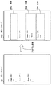
第1コード13は、アプリケーションのソースコードやオブジェクトコードを含む。第1コード13は、複数の第1コンポーネントを記載したコードである。第1コード13は、例えば、オブジェクトコードとして実行装置20に格納することも可能である。その場合、実行装置20は、複数のリクエストそれぞれの受信に応じて複数の第1コンポーネントの少なくとも一部を実行することになる。図1の例では、第1コンポーネントには、p1,p2,p3,p4が含まれる。第2コード14は、第1コード13から変更されたコードであって、複数の第2コンポーネントを記載したコードである。第2コード14は、例えば、オブジェクトコードとして実行装置20に格納することも可能である。その場合、実行装置20は、リクエストそれぞれの受信に応じて複数の第2コンポーネントの少なくとも一部を実行することになる。図1の例では、第2コード14に記載される第2コンポーネントには、p1,p2,p3,p4,p5が含まれる。以下では、実行装置20をリクエストの受信に応じてコンポーネントを実行する状態にすることを、実行装置20にコンポーネントを配備するという。なお、コンポーネントは、例えば、メソッドや関数の呼び出し単位や利用者指定のログ出力箇所単位、あるいはこれらの単位を組み合わせたものである。以下において、複数の第2コンポーネントのうち、複数の第1コンポーネントの何れとも異なる第2コンポーネントを差分コンポーネント14aと呼ぶ。
The
The first code 13 includes application source code and object code. The first code 13 is a code describing a plurality of first components. The first code 13 can be stored in the
第1ログ情報15は、複数の第2コンポーネントの一部である差分コンポーネント14aの実行状況を示す情報である。第2ログ情報16は、差分コンポーネント14aを含む複数の第2コンポーネントそれぞれの実行状況を示す情報である。パス情報17は、差分コンポーネント14aの実行に関連する関連リクエストに応じて実行される第2コンポーネントを示す情報である。
The 1st log information 15 is information which shows the execution situation of
分析部12は、記憶部11から第1コード13および第2コード14を読み出し、第1コード13と第2コード14を比較して差分コンポーネント14aを抽出する。図1の例では、分析部12は、差分コンポーネント14aとしてコンポーネントp5を抽出する。
The
分析部12は、複数の第2コンポーネントが配備された実行装置20に対し複数のリクエストを送信して、差分コンポーネント14aの実行状況を示す第1ログ情報15を取得する。このとき実行装置20に送信するリクエストは、例えば、少なくとも一部の第2コンポーネントを呼び出す可能性がある全てのリクエストである。分析部12は、実行装置20に対し、差分コンポーネント14aについてのみログを出力するよう指示してもよい。分析部12は、第1ログ情報15に基づき、差分コンポーネント14aの実行に関連する関連リクエストを特定する。図1の例では、分析部12は、実行装置20に対して、実行状況の監視対象をコンポーネントp5のみと指示し、全リクエストR1,R2,R3,R4,R5を順次送信してログを採取する。第1ログ情報15は、採取したログを表形式で表したものである。第1ログ情報15において、「−」は実行装置20がログを採取していないことを表す。空欄はリクエスト実行時にコンポーネントが実行されなかったことを表し、「1」はコンポーネントが実行されたことを表す。第1ログ情報15は、コンポーネントp1,p2,p3,p4についてのログが採取されていないことを示す。また、第1ログ情報15は、分析部12がリクエストR2とリクエストR4を送信したときに、コンポーネントp5が実行されたことを示す。分析部12は、第1ログ情報15に基づき、リクエストR2とリクエストR4を、差分コンポーネント14aに関連する関連リクエストとして特定する。
The
分析部12は、関連リクエストを実行装置20に送信し、関連リクエストに応じた差分コンポーネント14aを含む複数の第2コンポーネントの実行状況を示す第2ログ情報16を取得する。このとき実行装置20に送信するリクエストは、関連リクエストに限定され、関連リクエスト以外のリクエストを含まなくてよい。分析部12は、実行装置20に対し、差分コンポーネント14aを含む複数の第2コンポーネント、例えば、全第2コンポーネントについてログを出力するように指示してもよい。分析部12は、第2ログ情報16に基づき、複数の第2コンポーネントのうち、関連リクエストの受信に応じて実行される第2コンポーネントを示すパス情報17を生成する。図1の例では、実行装置20に対しログを採取する監視対象をコンポーネントp1,p2,p3,p4,p5と指示し、関連リクエストR2,R4を順次送信してログを採取する。第2ログ情報16の形式は、第1ログ情報15と同様である。第2ログ情報16は、リクエストR2を実行装置20に送信したときに、コンポーネントp1,p3,p4,p5が実行されたことを示す。同様に、リクエストR4を実行装置20に送信したときに、コンポーネントp2,p4,p5が実行されたことを示す。分析部12は、この第2ログ情報16に基づき、リクエストR2に関するパスとしてp1,p3,p4,p5を検出し、パス情報17に登録する。分析部12は、同様に、リクエストR4に関するパスとしてp2,p4,p5を検出し、パス情報17に登録する。
The
第1の実施の形態の分析装置10によれば、差分コンポーネント14aの実行状況を示す第1ログ情報15に基づいて差分コンポーネント14aの実行に関連する関連リクエストを特定する。続いて、分析装置10は、特定した関連リクエストを実行装置20に送信して、第2ログ情報16を生成し、パス情報17を生成する。パス情報17の生成では、実行装置20が関連リクエストの受信に応じて実行した第2コンポーネントに関する情報があればよい。このため、分析装置10では、第2ログ情報16を採取するときに、実行装置20へ送信するリクエストを関連リクエストに限定することができる。関連リクエストに限定することで、全リクエストを送信してログを採取する場合と比べて、ログの採取に要する処理時間を短縮できる。これにより、プログラムの分析の処理時間を短縮できる。
According to the
[第2の実施の形態]
次に、第2の実施の形態を説明する。
図2は、第2の実施の形態の分析装置のハードウェア例を示すブロック図である。
[Second Embodiment]
Next, a second embodiment will be described.
FIG. 2 is a block diagram illustrating a hardware example of the analysis apparatus according to the second embodiment.
第2の実施の形態の分析装置100は、旧プログラムの一部を変更した新プログラムに関し、運用前の事前分析を支援する。分析装置100は、CPU101、RAM102、HDD103、画像信号処理部104、入力信号処理部105、媒体リーダ106および通信インタフェース107を有する。上記のユニットは、バス108に接続されている。
The
CPU101は、プログラムの命令を実行する演算回路を含むプロセッサである。CPU101は、HDD103に記憶されたプログラムやデータの少なくとも一部をRAM102にロードし、プログラムを実行する。なお、CPU101は複数のプロセッサコアを備えてもよく、分析装置100は複数のプロセッサを備えてもよく、以下で説明する処理を複数のプロセッサまたはプロセッサコアを用いて並列に実行してもよい。
The
RAM102は、CPU101が実行するプログラムやCPU101が演算に用いるデータを一時的に記憶する揮発性の半導体メモリである。なお、分析装置100は、RAM以外の種類のメモリを備えてもよく、複数個のメモリを備えてもよい。
The
HDD103は、OS(Operating System)やミドルウェアやアプリケーションソフトウェアなどのソフトウェアのプログラム、および、データを記憶する不揮発性の記憶装置である。プログラムには、分析プログラムが含まれる。なお、分析装置100は、フラッシュメモリやSSD(Solid State Drive)などの他の種類の記憶装置を備えてもよく、複数の不揮発性の記憶装置を備えてもよい。
The
画像信号処理部104は、CPU101からの命令に従って、分析装置100に接続されたディスプレイ111に画像を出力する。ディスプレイ111としては、CRT(Cathode Ray Tube)ディスプレイ、液晶ディスプレイ(LCD:Liquid Crystal Display)、プラズマディスプレイ(PDP:Plasma Display Panel)、有機EL(OEL:Organic Electro-Luminescence)ディスプレイなどを用いることができる。
The image
入力信号処理部105は、分析装置100に接続された入力デバイス112から入力信号を取得し、CPU101に出力する。入力デバイス112としては、マウスやタッチパネルやタッチパッドやトラックボールなどのポインティングデバイス、キーボード、リモートコントローラ、ボタンスイッチなどを用いることができる。また、分析装置100に、複数の種類の入力デバイスが接続されていてもよい。
The input
媒体リーダ106は、記録媒体113に記録されたプログラムやデータを読み取る読み取り装置である。記録媒体113として、例えば、フレキシブルディスク(FD:Flexible Disk)やHDDなどの磁気ディスク、CD(Compact Disc)やDVD(Digital Versatile Disc)などの光ディスク、光磁気ディスク(MO:Magneto-Optical disk)、半導体メモリなどを使用できる。媒体リーダ106は、例えば、記録媒体113から読み取ったプログラムやデータをRAM102またはHDD103に格納する。
The
通信インタフェース107は、ネットワーク114に接続され、ネットワーク114を介して他のコンピュータと通信を行うことができる。通信インタフェース107は、スイッチなどの通信装置とケーブルで接続される有線通信インタフェースでもよいし、アクセスポイントと無線リンクで接続される無線通信インタフェースでもよい。
The
なお、分析装置100は、媒体リーダ106を備えなくてもよい。また、ユーザが操作する端末装置からネットワーク114経由で分析装置100にアクセスできる場合、分析装置100は、画像信号処理部104や入力信号処理部105を備えなくてもよい。また、ディスプレイ111や入力デバイス112が、分析装置100の筐体と一体に形成されてもよい。分析装置100は、第1の実施の形態の分析装置10に対応する。RAM102またはHDD103は、第1の実施の形態の記憶部11に対応する。CPU101は、第1の実施の形態の分析部12に対応する。
Note that the
図3は、第2の実施の形態の分析装置の機能例を示すブロック図である。
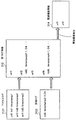
分析装置100は、記憶部120、パス分析部130、ログ情報採取部140および表示制御部150を有する。記憶部120は、RAM102またはHDD103に確保した記憶領域として実現できる。パス分析部130、ログ情報採取部140および表示制御部150は、CPU101が実行するプログラムのモジュールとして実現できる。
FIG. 3 is a block diagram illustrating an example of functions of the analyzer according to the second embodiment.
The
記憶部120は、旧ソースコード201、旧コンポーネント定義情報202、旧パス情報203、新ソースコード204、新コンポーネント定義情報205、新パス情報206、リクエスト情報211、第1ログ情報212、第2ログ情報213、関連機能情報214および差分パス情報215を記憶する。
The storage unit 120 includes an
旧ソースコード201は、既存のソースコードであり、既に事前分析が行われ、対応する旧コンポーネント定義情報202および旧パス情報203が生成されている。ソースコードは、人間が理解容易なプログラミング言語を用いて記述される。旧コンポーネント定義情報202は、旧ソースコード201に含まれるコンポーネントを定義した情報である。コンポーネントは、パス分析部130が予め決められた規則に従ってソースコードを区切った単位である。コンポーネントには、例えば、メソッド、クラス、if文や{}で区切られたブロック、利用者指定のログ出力箇所などを単位として、これらの単位が1または複数含まれる。旧パス情報203は、旧ソースコード201について事前分析されたパスに関する情報である。パスは、リクエストによって呼び出されるリクエスト単位によって実行されるコンポーネントの集合である。第2の実施の形態では、提供するサービスをWebサービスとする。Webサービスのリクエスト単位は、URL(Uniform Resource Locator)+CGI(Common Gateway Interface)/POSTパラメータなどで表す。以下の説明ではこのリクエスト単位を「機能」と呼ぶ。
The
新ソースコード204は、旧ソースコード201の一部が更新されたソースコードである。更新には、コンポーネントの追加、削除、変更がある。新コンポーネント定義情報205は、新ソースコード204に含まれるコンポーネントを定義した情報である。新コンポーネント定義情報205は、パス分析部130が、新ソースコード204について旧コンポーネント定義情報202と同様の処理を行って生成する。
The
リクエスト情報211には、機能を利用するリクエストパターンが登録される。リクエストパターンは、例えば、機能に紐付けされており、リクエスト情報211から任意の機能を利用するリクエストパターンを抽出することができる。リクエストパターンは、例えば、テスト用のシナリオに基づいて作成しておくか、または、運用時に採取しておく。第1ログ情報212は、新ソースコード204中の旧ソースコード201と異なる差分コードに関連する機能の特定に用いるログ情報である。第2ログ情報213は、特定された差分コードに関連する機能のパスの検出に用いるログ情報である。関連機能情報214は、新ソースコード204中の差分コードに関連する機能に関する情報である。差分パス情報215は、新ソースコード204中の関連機能情報214に登録される機能が呼び出すコンポーネントを含むパスの情報である。
In the
パス分析部130は、旧ソースコード201と、新ソースコード204とを比較し、差分を抽出する。パス分析部130は、新ソースコード204に追加されている部分があるときは、追加部分に含まれる追加コンポーネントを抽出する。パス分析部130は、追加コンポーネントについて詳細ログの出力を設定し、全リクエストパターンによるログの取得をログ情報採取部140に指示し、第1ログ情報212を取得する。パス分析部130は、第1ログ情報212に基づいて、追加コンポーネントに関連する機能を特定し、関連機能情報214に登録する。また、パス分析部130は、新ソースコード204に削除部分または変更部分があるときは、旧コンポーネント定義情報202に基づき、変更された変更コンポーネントおよび削除された削除コンポーネントを抽出する。続いて、パス分析部130は、旧パス情報203に基づき、変更コンポーネントおよび削除コンポーネントに関する機能を特定し、関連機能情報214に登録する。こうして、関連機能情報214には、旧ソースコード201を新ソースコード204に更新するときに、追加、変更および削除された全てのコンポーネント(以下において差分コンポーネントとする)に関連する機能が登録される。パス分析部130は、全コンポーネントの詳細ログの出力を設定し、関連機能情報214に登録される機能に対応するリクエストを用いたログ採取をログ情報採取部140に指示し、第2ログ情報213を得る。パス分析部130は、第2ログ情報に基づいて、各機能のパスを検出し、差分パス情報215を生成する。そして、パス分析部130は、旧パス情報203と差分パス情報215とを合成し、新パス情報206を生成する。
The
ログ情報採取部140は、ネットワーク114を介して対象のアプリケーションを実行するサーバ300と接続し、パス分析部130に従ってリクエストの送信と、ログ情報の採取を行う。サーバ300は、例えば、Webサーバであり、リクエストを受信すると、リクエストに応じた処理を実行する。サーバ300には、リクエストの送信前に詳細ログを出力する設定がなされる。分析装置100は、例えば、Java(登録商標)のバイトコードインジェクションによってサーバ300に対し、所望のコンポーネントの詳細ログ出力を設定する。また、予め、サーバ300に詳細ログ出力の設定処理を埋め込んでおき、分析装置100からの設定指示で任意のコンポーネントの詳細ログを採取できるようにするとしてもよい。以下において、「詳細ログ出力を設定する」処理は、上記のような手順によって、サーバ300が指定されたコンポーネントの詳細ログを出力する状態を設定する手順を指す。また、分析装置100では、パス分析部130からの指示によってログ情報採取部140が指定されたコンポーネントの詳細ログ出力の設定を行う。リクエストを受け取ったサーバ300は、リクエストに応じた処理を実行し、アクセスログと、アクセスログに対応する詳細ログを生成する。詳細ログは、設定によって指定されたコンポーネントについて生成される。ログ情報採取部140は、リクエストを送信したサーバ300からログ情報としてアクセスログと詳細ログを取得し、第1ログ情報212および第2ログ情報213を生成する。
The log
表示制御部150は、例えば、パス分析部130による新ソースコード204に関するパス分析の終了後、パス分析部130による分析結果を画像信号処理部104経由でディスプレイ111に表示する表示制御を行う。表示制御部150は、例えば、差分パス情報215に基づいて、変更されたコンポーネントの呼び出し関係を示す表示情報を生成し、ディスプレイ111に表示する。
For example, after the path analysis on the
以下、具体例を挙げて説明する。分析装置100は、旧ソースコード201の一部を更新した新ソースコード204の事前分析を行う。旧ソースコード201については、既に、旧コンポーネント定義情報202および旧パス情報203が生成され、記憶部120に記憶されている。
Hereinafter, a specific example will be described. The
図4は、旧ソースコードと新ソースコードの例を示す図である。
新ソースコード204は、旧ソースコード201の一部を更新したプログラムである。図4の例では、新ソースコード204の点線で囲む部分が旧ソースコード201から更新されている。追加204a部分では、「class C4{・・・}」のクラスが追加されている。変更204b部分では、旧ソースコード201の「class C3{・・・}」に「C4」を加える変更が行われている。削除204c部分では、旧ソースコード201の「class C0{・・・}」が削除されている。なお、C0,C1,C3,C4はそれぞれクラス名を表す。
FIG. 4 is a diagram illustrating an example of an old source code and a new source code.
The
パス分析部130は、新ソースコード204を分析し、新コンポーネント定義情報205を生成する。パス分析部130は、例えば、同じ階層など、予め決められた規則に基づいて、新ソースコード204のクラスやメソッド、ブロックなどをコンポーネントに割り当てる。なお、新ソースコード204による新コンポーネント定義情報205の生成は、パス分析部130による分析処理の前に事前に生成されていてもよい。
The
図5は、旧コンポーネント定義情報および新コンポーネント定義情報の例を示す図である。
旧コンポーネント定義情報202は、旧ソースコード201のコンポーネントと、コンポーネントに含まれるクラス、メソッド、ブロックとが対応付けられた情報である。図5の例の旧コンポーネント定義情報202では、コンポーネントBには、クラスC1とブロックB3が含まれ、コンポーネントCには、クラスC2が含まれることを示している。
FIG. 5 is a diagram illustrating an example of old component definition information and new component definition information.
The old
新コンポーネント定義情報205は、新ソースコード204の新コンポーネントと、新コンポーネントに含まれるクラスなどが対応付けられた情報である。図5の例の新コンポーネント定義情報205は、コンポーネントA,B,C,Dについては、旧コンポーネント定義情報202と同じである。また、新コンポーネント定義情報205には、新ソースコード204で新たに追加されたクラスC4に対応して、新コンポーネントEが定義されている。一方、新コンポーネント定義情報205では、新ソースコード204で削除されたクラスC0に関し、旧コンポーネント定義情報202のクラスC0に対応するコンポーネントFが削除されている。
The new
パス分析部130は、新コンポーネント定義情報205と、旧コンポーネント定義情報202とに基づいて、新ソースコード204で追加されたコンポーネントEに関連する関連機能を特定する処理を行う。関連機能を特定することを目的とする第1ログ情報212の取得では、コンポーネントEに関連する機能が特定できればよいので、詳細ログの対象はコンポーネントEに限定する。また、どのような機能がコンポーネントEを呼び出すかは特定できないので、全リクエストパターンを送信し、全機能を呼び出す。パス分析部130は、コンポーネントEを詳細ログの出力対象とし、全てのリクエストパターンを送信してログを採取するようにログ情報採取部140に指示する。ログ情報採取部140は、コンポーネントEの詳細ログ出力を設定し、リクエスト情報211に格納される全リクエストパターンのリクエストをサーバ300に順次送信する。ログ情報採取部140は、全リクエストパターンの送信を終了した後、リクエストを実行したサーバ300からアクセスログと詳細ログを採取し、第1ログ情報212を生成する。なお、サーバ300からのアクセスログと詳細ログの採取は、リクエストの送信ごとに行ってもよい。
Based on the new
図6は、第1ログ情報と関連機能情報の例を示す図である。
アクセスログ2121は、ログ情報採取部140がリクエストを送信することによって呼び出された機能に関するアクセス情報である。アクセスログ2121は、サーバ300がリクエストを受け付けたときにサーバ300によって採取される。図6の例では、アクセスログ2121は、呼び出し先のURL情報(url)と、トランザクションid(tid)と、タイムスタンプ(timestamp)を含む。詳細ログ2122は、機能を実行したサーバ300が指定されたクラスやメソッドを利用したときの利用履歴に関する情報である。詳細ログ2122は、リクエストに応じてサーバ300上で指定されたコンポーネントが起動されたときにサーバ300によって採取される。図6の例では、詳細ログ2122は、トランザクションid(tid)と、タイムスタンプ(timestamp)と、呼び出したクラス名やメソッド名と、を含む。
FIG. 6 is a diagram illustrating an example of first log information and related function information.
The access log 2121 is access information related to a function called by the log
ログ情報採取部140は、アクセスログ2121および詳細ログ2122に基づき、機能(url)ごとに対応する詳細ログをまとめた第1ログ情報212を生成し、記憶部120に格納する。第1ログ情報212には、全リクエストパターンを実行して得られた全機能について、指定されたコンポーネントE(クラスC4)の詳細ログが設定されている。機能とコンポーネントの関係は、トランザクションidを用いて判断することが可能である。図6の例では、機能「url1」は、コンポーネントE(クラスC4)に関する詳細ログがない。すなわち、機能「url1」では、コンポーネントE(クラスC4)は利用されていない。また、機能「url2」は、コンポーネントE(クラスC4)を利用したという詳細ログがある。すなわち、機能「url2」は、コンポーネントE(クラスC4)を利用する。同様に、機能「url3」がコンポーネントEを利用せず、機能「url4」がコンポーネントEを利用する。
Based on the access log 2121 and the
なお、上記の例では、詳細ログの対象コンポーネントは1つであったが、複数の場合も同様である。ログ情報採取部140は、詳細ログの対象コンポーネントを全て指定し、全リクエストパターンを送信してログを採取する。また、ログ情報採取部140は、アクセスログ2121と、詳細ログ2122とをそれぞれ取得するとしたが、例えば、サーバ300が詳細ログ2122にアクセスログ2121の内容を付加した情報を送付するとしてもよい。
In the above example, there is only one target component for the detailed log, but the same applies to a plurality of components. The log
このように、ログ情報採取部140による第1ログ情報212の採取は、詳細ログを取得する対象を新ソースコード204に新たに追加されたコンポーネントに限定して行う。
パス分析部130は、第1ログ情報212に基づき、詳細ログの対象を呼び出したURLを関連機能として特定する。図6の例では、url2とurl4を関連機能として抽出し、関連機能情報214に登録する。この時点では、追加コンポーネントに対応する関連機能の特定が終了しているのみであるので、続いて変更コンポーネントおよび削除コンポーネントについて関連機能の特定を行う。
As described above, the collection of the
Based on the
図7は、変更・削除コンポーネントの関連機能の特定処理の例を示す図である。
パス分析部130は、旧コンポーネント定義情報202と、旧パス情報203とに基づき、新ソースコード204に更新する際に変更および削除されたコンポーネントに関連する関連機能を特定する。
FIG. 7 is a diagram illustrating an example of the specifying process of the related function of the change / delete component.
Based on the old
パス分析部130は、旧ソースコード201と新ソースコード204との比較によって、新ソースコード204では、クラスC0が削除され、クラスC3が変更されていることを検出している。コンポーネントの変更と削除では、このコンポーネントを利用する側の機能に変更は生じない。パス分析部130は、旧コンポーネント定義情報202および旧パス情報203を用いて、関連する機能を特定することができる。図7の例では、パス分析部130は、変更されたクラス「C3」を含むコンポーネント「D」を変更コンポーネント、削除されたクラス「C0」を含むコンポーネント「F」を削除コンポーネントとして抽出する。パス分析部130は、旧パス情報203に基づいて、抽出したコンポーネントD,Fに対応する機能を特定する。例えば、旧パス情報203には、機能「url3」、「url4」は、コンポーネント「D」を利用することが登録されている。パス分析部130は、旧パス情報203に基づいて、url3とurl4を関連機能として抽出する。同様に、旧パス情報203に基づき、コンポーネントFの関連機能として、url5を抽出する。パス分析部130は、抽出した関連機能を関連機能情報214に追加登録する。これにより、関連機能情報214には、追加コンポーネントについて特定した関連機能と、変更コンポーネントおよび削除コンポーネントについて特定した関連機能とが登録される。
By comparing the
以上の処理手順が実行されることにより、分析装置100は、新ソースコード204において更新された差分部分に含まれるコンポーネントに関連する関連機能を抽出する。新ソースコード204の静的な解析では、運用時にパラメータの取り得る値の組み合わせを検出することが難しいため、関連機能の特定はできない。分析装置100では、上記の処理によって、関連機能の特定が可能となる。
By executing the above processing procedure, the
次に、パス分析部130は、関連機能情報214に基づいて、関連機能に関する第2ログ情報213を取得する処理を行う。第2ログ情報213は、関連機能が利用するコンポーネントを検出することを目的とする。パス分析部130は、全コンポーネントについて詳細ログ出力を設定し、送信するリクエストパターンを関連機能に限定してログ採取を行うようにログ情報採取部140に指示する。ログ情報採取部140は、全コンポーネントの詳細ログ出力を設定し、リクエスト情報211から関連機能を呼び出すリクエストパターンを抽出する。ログ情報採取部140は、抽出したリクエストパターンに基づいてサーバ300にリクエストを送信する。リクエストを受け付けたサーバ300は、全コンポーネントの詳細ログ出力の設定に基づき、リクエストに応じた処理でコンポーネントを利用するごとにその詳細ログを生成する。ログ情報採取部140は、サーバ300が生成した詳細ログおよびアクセスログを取得する。ログ情報採取部140は、関連機能を呼び出す全リクエストパターンについてサーバ300にリクエストを送信し、サーバ300からアクセスログおよび詳細ログの採取を行って第2ログ情報213を生成する。なお、対象のサーバが複数の場合は、それぞれのサーバについて全コンポーネントの詳細ログ出力を設定し、リクエストの送信とログの採取を行う。このように、サーバに送信するリクエストパターンを関連機能に限定することによって、全リクエストパターンを送信してログを採取する場合と比較し、ログ採取に要する処理時間を短縮することができる。また、関連機能に限定するため、関連機能の数が少ない場合は、より処理時間を短縮できる。
Next, the
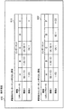
図8は、第2ログ情報と差分パス情報の例を示す図である。図8は、図7に示す関連機能url2,url3,url4,url5についてログ情報採取部140が採取した情報を示している。
FIG. 8 is a diagram illustrating an example of the second log information and the difference path information. FIG. 8 shows information collected by the log
第2ログ情報213は、機能ごとに、サーバ300から採取した詳細ログが記録されている。図8の例では、url2(213a)は、ブロックB1、クラスC2、クラスC3およびクラスC4を利用したことを示している。url3(213b)は、クラスC1、クラスC2およびクラスC3を利用したことを示している。url4(213c)は、クラスC1、クラスC3、クラスC4を利用したことを示している。そして、url5(213d)は、ブロックB1を利用したことを示している。
In the
パス分析部130は、新コンポーネント定義情報205に基づき、第2ログ情報213の各機能に対応するコンポーネントを特定し、差分パス情報215に登録する。図8の例では、url2が利用するコンポーネントとして、ブロックB1を含むコンポーネントA、クラスC2を含むコンポーネントC、クラスC3を含むコンポーネントDおよびクラスC4を含むコンポーネントEを登録する。パス分析部130は、同様の処理をurl3,url4,url5について実行し、関連機能に対応する差分パス情報215を生成する。
The
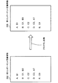
図9は、新パス情報の設定処理の例を示す図である。
パス分析部130は、差分パス情報215と、旧パス情報203とを合成して、新パス情報206を生成する。図9の例では、旧パス情報203には、機能url1,url2,url3,url4,url5についてパス情報が登録されている。このうち、差分パス情報215に登録されている機能url2,url3,url4,url5については、新たなパスが検出されている。
FIG. 9 is a diagram illustrating an example of a new path information setting process.
The
ここで、新ソースコード204に対応する機能のうち、パス分析部130が特定した関連機能以外の機能のパスは、旧パス情報203と同様である。よって、パス分析部130は、新ソースコード204に対応する機能のうち、差分パス情報215に登録された機能のパスについては差分パス情報215の情報を選択する。一方、パス分析部130は、差分パス情報215に登録されていない機能のパスについては、旧パス情報203の情報を選択する。パス分析部130は、このようにして差分パス情報215と旧パス情報203を合成し、新ソースコード204に対応する新パス情報206を生成する。パス分析部130は、生成した新パス情報206を記憶部120に格納する。
Here, among the functions corresponding to the
以上の処理によって、分析装置100は新ソースコード204に対応する新パス情報206を生成し、記憶部120に格納する。これにより、例えば、新ソースコード204の運用時の不具合の分析に新パス情報206を利用することができる。
Through the above processing, the
このように、分析装置100によれば、新ソースコード204の事前分析において、旧ソースコード201からの差分部分に対応する関連機能に限定したリクエストパターンを送信し、パス分析に必要な第2ログ情報213を採取する。これにより、全機能に対応する全リクエストパターンを送信してログを採取する場合と比較し、事前分析処理に要する処理時間を短縮することができる。特に、分析装置100は、関連機能に限定してログを採取するので、特定した関連機能の数が少ないほど、事前分析処理に要する処理時間を短縮することができる。
Thus, according to the
次に、分析装置100による事前分析処理の手順について、フローチャートを用いて説明する。
図10は、事前分析処理の手順例を示すフローチャートである。
Next, the procedure of the pre-analysis process by the
FIG. 10 is a flowchart illustrating a procedure example of the pre-analysis process.
[ステップS10]パス分析部130は、記憶部120に格納される新ソースコード204と旧ソースコード201を比較し、新ソースコード204中の旧ソースコード201と異なる差分部分を検出する。
[Step S10] The
[ステップS11]パス分析部130は、差分部分を解析し、差分部分に応じたコンポーネントを抽出する。パス分析部130は、差分部分に応じたコンポーネントとして、新ソースコード204において追加された追加コンポーネントと、変更された変更コンポーネントと、削除された削除コンポーネントを抽出する。
[Step S11] The
[ステップS12]パス分析部130は、追加コンポーネント、削除コンポーネントおよび変更コンポーネントに関連する関連機能を特定する関連機能特定処理を行う。関連機能特定処理の詳細は、図11のフローチャートを用いて説明する。
[Step S12] The
[ステップS13]パス分析部130は、特定した関連機能について、第2ログ情報213を取得する。第2ログ情報213は、関連機能の実行時に利用されたコンポーネントに関する情報である。パス分析部130は、ログ情報採取部140に対し、全コンポーネントの詳細ログ出力を設定し、関連機能を呼び出すリクエストパターンを送信してログ採取を行うよう指示する。ログ情報採取部140は、パス分析部130の指示に基づいて、サーバ300に全コンポーネントの詳細ログ出力を設定し、関連機能に対応するリクエストをサーバ300に送信する。ログ情報採取部140は、サーバ300がリクエストに応じた処理を実行して生成した詳細ログおよびアクセスログをサーバ300から採取する。ログ情報採取部140は、採取した詳細ログとアクセスログに基づき、関連機能と、関連機能が利用したコンポーネントとを対応付けた第2ログ情報213を生成し、記憶部120に格納する。
[Step S13] The
[ステップS14]パス分析部130は、第2ログ情報213に基づき、関連機能に関する差分パス情報215を生成し、記憶部120に格納する。
[ステップS15]パス分析部130は、差分パス情報215に対応する旧パス情報203のパスを差分パス情報215のパスに置き換え、新パス情報206を生成する。パス分析部130は、生成した新パス情報206を記憶部120に格納する。
[Step S <b> 14] The
[Step S15] The
図11は、関連機能特定処理の手順例を示すフローチャートである。
新ソースコード204中の旧ソースコード201と異なる差分部分に応じた差分コンポーネントが抽出されて、処理が開始される。
FIG. 11 is a flowchart illustrating an exemplary procedure of related function identification processing.
A difference component corresponding to a difference portion different from the
[ステップS121]パス分析部130は、抽出された差分コンポーネントの中に追加コンポーネントがあるか否かを判定する。パス分析部130は、追加コンポーネントがあるときは処理をステップS122に進め、追加コンポーネントがないときは処理をステップS125に進める。
[Step S121] The
[ステップS122]パス分析部130は、追加コンポーネントについてのみ詳細ログを出力する設定をログ情報採取部140に指示する。
[ステップS123]パス分析部130は、ログ情報採取部140に対し、ステップS122において指示した設定で、全リクエストパターンを送信してログを採取するように指示する。ログ情報採取部140は、追加コンポーネントのみの詳細ログ出力を設定し、全リクエストパターンのリクエストをサーバ300に順次送信する。ログ情報採取部140は、リクエストに応じた機能を実行したサーバ300が生成した詳細ログとアクセスログを取得し、第1ログ情報212を生成する。
[Step S122] The
[Step S123] The
[ステップS124]パス分析部130は、第1ログ情報212から追加コンポーネントを利用する関連機能を抽出する。
[ステップS125]パス分析部130は、旧コンポーネント定義情報202に基づいて、変更コンポーネントおよび削除コンポーネントを利用する機能を抽出する。
[Step S124] The
[Step S125] Based on the old
[ステップS126]パス分析部130は、追加コンポーネントに対応する関連機能に、変更コンポーネントおよび削除コンポーネントに対応する機能を加え、関連機能として保持する。
[Step S126] The
以上の処理手順が実行されることにより、新ソースコード204において追加、変更および削除された差分コンポーネントに関連する関連機能が抽出される。分析装置100では、このようにして関連機能を特定することによって、新ソースコード204の事前分析において関連機能に限定してログを採取し、新パス情報206を生成することができる。これにより、分析装置100では、新ソースコード204の全機能に対応する全リクエストパターンを用いてログの採取を行う場合と比較し、事前分析に要する処理時間を短縮することができる。
By executing the above processing procedure, related functions related to the difference component added, changed, and deleted in the
分析装置100は、生成したパス情報を利用者に提供することができる。分析装置100は、外部装置からの要求に応じて、記憶部120に格納する旧パス情報203、差分パス情報215および新パス情報206を提供することができる。また、例えば、分析装置100は、パス情報に基づくコンポーネントの呼び出し関係を表示画面に表示して利用者に示すことができる。
The
図12は、コンポーネントの呼び出し関係表の表示画面の例を示す図である。
表示画面610は、更新前のコンポーネント呼び出し関係の表611と、更新後のコンポーネント呼び出し関係の表612を表示する。図12の例では、「機能1」および「機能2」は、新ソースコード204において検出された差分コンポーネントを利用する関連機能である。また、各機能に対応する欄において、「1」は対象のコンポーネントを表す。その左隣の()は対象のコンポーネントの呼び出し元のコンポーネントを示し、右隣の()は対象のコンポーネントが呼び出すコンポーネントを示す。例えば、更新前のコンポーネント呼び出し関係の表611の「(B)1(C)」は、リクエストに応じた「機能1」の処理において、コンポーネントBがコンポーネントAを呼び出し、コンポーネントAがコンポーネントCを呼び出したことを示す。
FIG. 12 is a diagram illustrating an example of a display screen of a component call relation table.
The
更新前のコンポーネント呼び出し関係の表611は、表示制御部150が、差分パス情報215および旧パス情報203に基づいて生成する。表示制御部150は、旧パス情報203のうち、差分パス情報215に対応する機能のパスを抽出し、機能とコンポーネントの対応表を生成する。なお、呼び出し元と呼び出し先の呼び出し関係は、表示制御部150が、例えば、第2ログ情報213に基づいて検出する。また、パス分析部130が、パスの抽出時に呼び出し関係を抽出しておいてもよい。
The
更新後のコンポーネント呼び出し関係の表612は、表示制御部150が、差分パス情報215に基づいて生成する。表示制御部150は、差分パス情報215に登録されている機能とそのパスとの対応表を生成する。
The updated component call table 612 is generated by the
このように、プログラムの更新前と更新後で変更を検出したパス情報を表示画面に表示することにより、利用者が更新に伴って変更されたパスの確認を容易に行うことができる。利用者は、表示画面610から、例えば、新ソースコード204では、「機能2」に追加したコンポーネント「D」が、コンポーネント「E」から呼び出されることを確認できる。例えば、利用者は、更新前のコンポーネント呼び出し関係の表611と、更新後のコンポーネント呼び出し関係の表612とを比較することにより、機能による意図しないコンポーネント呼び出しを容易に発見することができる。
As described above, by displaying the path information in which the change is detected before and after the update of the program on the display screen, the user can easily confirm the path that has been changed along with the update. The user can confirm from the
なお、表示制御部150は、更新後のコンポーネント呼び出し関係の表612の更新前のコンポーネント呼び出しの表611と異なる箇所を強調表示するとしてもよい。これにより、利用者の確認をより容易にすることができる。
Note that the
また、表示制御部150は、コンポーネントの呼び出し関係を関係図で提供するとしてもよい。
図13は、コンポーネントの呼び出し関係図の表示画面の例を示す図である。図13は、図12に示したコンポーネントの呼び出し関係を図形式で表示した表示画面である。
Further, the
FIG. 13 is a diagram illustrating an example of a display screen of a component call relation diagram. FIG. 13 is a display screen displaying the calling relationship of the components shown in FIG. 12 in a diagram format.
コンポーネントの呼び出し関係図を示す表示画面620は、更新前のコンポーネント呼び出し関係図621と、更新後のコンポーネント呼び出し関係図622と、を表示する。図13に示す表示画面620の「F1」は図12の「機能1」に対応し、同様に「F2」は「機能2」に対応する。「A」、「B」、「C」、「D」、「E」は、コンポーネントに対応する。このように、コンポーネントの呼び出し関係を関係図にすることにより、利用者はより容易に新ソースコード204のコンポーネントの呼び出し関係を確認できる。
The
また、分析装置100では、新パス情報206を生成する際、新パス情報206に版数を設定するとしてもよい。パス分析部130は、例えば、解析を行った新ソースコード204の版数を取得し、新パス情報206に設定した版数と対応付けて記憶部120に格納しておく。これにより、例えば、運用時に不具合が検出されたアプリケーションの不具合箇所を検出する際、対象のアプリケーションに応じたパス情報を選択して利用することができる。
In the
上記のように、分析装置100が生成するパス情報によって、利用者は、ソースコードを静的に解析するだけではわからないリクエスト送信時のコンポーネントの呼び出し関係を把握することが可能となる。例えば、アプリケーションのデバッグ時に、旧パス情報203と新パス情報206を比較することによって、同じリクエストパターンに対するコンポーネントの呼び出し関係の変化を検出できる。これにより、デバッグが容易になる。また、パス情報は、アプリケーションの運用時において、サーバ300で遅延が発生した場合の原因の絞り込みに利用することができる。例えば、あるリクエストパターンのみサーバ300で遅延が発生した場合に、その原因となっているコンポーネント群を特定することができる。これにより、遅延発生時における原因分析に要する時間を短縮することができる。
As described above, the path information generated by the
また、上記の分析装置100は、関連機能に限定してログの採取を行って新パス情報206を生成するとしたが、限定によって事前分析の処理時間が短縮できないときは、全機能についてログを採取する通常のログ採取を行うとしてもよい。例えば、特定した関連機能の数が多くなるにつれて、第2ログ情報213の取得に用いるリクエストパターンも増加し、第2ログ情報213を取得する時間も増加する。また、パス分析部130は、第2ログ情報213に基づいて差分パス情報215を生成した後、旧パス情報203と合成して新パス情報206を生成する。関連機能の数に応じて、差分パス情報215と、旧パス情報203とを合成する処理時間も増大する。このため、関連機能に限定した第2ログ情報213の取得に要する時間と、新パス情報206を生成する処理時間とを合わせた処理時間が、従来の手法による処理時間より短縮されない場合がある。従来の手法とは、全機能に対応する全リクエストパターンについて全コンポーネントの詳細ログを取得し、新パス情報を生成する手法である。パス分析部130は、第2ログ情報213の取得を開始する前に、第2ログ情報213を取得した場合の処理時間H1と、従来の手法による処理時間H2とを算出し、時間が短い方を選択するとしてもよい。
In addition, the
第2ログ情報213を用いる場合の処理時間H1は、次の式で表すことができる。
H1= 関連機能のログ採取時間+差分パス情報の生成と旧パス情報との合成処理時間
一方、従来の手法による処理時間H2は、次の式で表すことができる。
The processing time H1 when using the
H1 = related function log collection time + differential path information generation and old path information synthesis processing time On the other hand, the processing time H2 according to the conventional method can be expressed by the following equation.
H2= 全リクエストパターンによるログ採取時間+新パス情報生成時間
ログ採取時間は、例えば、事前に、全コンポーネントについて詳細ログを出力した場合に要する時間を機能ごとに計測しておく。また、例えば、シミュレーションなどによって各コンポーネントが詳細ログを出力した場合の処理時間を設定し、設定した処理時間に基づいて機能ごとの処理時間を算出してもよい。コンポーネントの処理時間は、粒度(クラス単位、メソッド単位など)に応じて調整してもよい。分析装置100は、いずれかの方法によって、事前に、機能ごとのログ採取時間を算出し、記憶部120に格納しておく。また、差分パス情報215の生成に要する処理時間、旧パス情報203との合成処理時間も予め設定しておく。全リクエストパターンのログから新パス情報の生成に要する時間も設定しておく。それぞれの処理について事前に計測した時間を設定しておいてもよいし、シミュレーションなどによって設定してもよい。また、例えば、1つの機能のパス情報を生成するのに要する時間を設定しておき、機能数に応じた処理時間を求めるとしてもよい。
H2 = log collection time based on all request patterns + new path information generation time As the log collection time, for example, the time required for outputting detailed logs for all components is measured in advance for each function. Further, for example, a processing time when each component outputs a detailed log by simulation or the like may be set, and the processing time for each function may be calculated based on the set processing time. The processing time of the component may be adjusted according to the granularity (class unit, method unit, etc.). The
パス分析部130は、第2ログ情報213の採取前に、上記の算出式に基づいて処理時間H1と、処理時間H2を算出する。パス分析部130は、処理時間H1について、関連機能の処理時間を積算し、差分パス情報の生成と合成の処理時間を加えて算出する。また、パス分析部130は、処理時間H2について、全機能の処理時間を積算し、新パス情報の生成に要する処理時間を加えて算出する。パス分析部130は、算出した処理時間H1と、処理時間H2を比較し、いずれの処理を行うか判定する。パス分析部130は、H1<H2であるときは、関連機能に限定したログ採取を行ってパス情報を生成する。パス分析部130は、また、H1≧H2であるときは、全機能のログ採取を行ってパス情報を生成する。
The
分析装置100は、ログ採取に要する時間を算出し、関連機能に限定したログ採取で時間短縮を図れるか否かを判定し、時間短縮を図れるときのみ関連機能に限定したログ採取を行う。これにより、より効果的に事前分析に要する処理時間を短縮することができる。
The
なお、第1の実施の形態の情報処理は、分析装置10にプログラムを実行させることで実現できる。第2の実施の形態の情報処理は、分析装置100にプログラムを実行させることで実現できる。
Note that the information processing of the first embodiment can be realized by causing the
プログラムは、コンピュータ読み取り可能な記録媒体(例えば、記録媒体113)に記録しておくことができる。記録媒体としては、例えば、磁気ディスク、光ディスク、光磁気ディスク、半導体メモリなどを使用できる。磁気ディスクには、FDおよびHDDが含まれる。光ディスクには、CD、CD−R(Recordable)/RW(Rewritable)、DVDおよびDVD−R/RWが含まれる。プログラムは、可搬型の記録媒体に記録されて配布されることがある。その場合、可搬型の記録媒体からHDDなどの他の記録媒体(例えば、HDD103)にプログラムをコピーして実行してもよい。 The program can be recorded on a computer-readable recording medium (for example, the recording medium 113). As the recording medium, for example, a magnetic disk, an optical disk, a magneto-optical disk, a semiconductor memory, or the like can be used. Magnetic disks include FD and HDD. Optical discs include CD, CD-R (Recordable) / RW (Rewritable), DVD, and DVD-R / RW. The program may be recorded and distributed on a portable recording medium. In this case, the program may be copied from a portable recording medium to another recording medium such as an HDD (for example, the HDD 103) and executed.
10 分析装置
11 記憶部
12 分析部
13 第1コード
14 第2コード
14a 差分コンポーネント
15 第1ログ情報
16 第2ログ情報
17 パス情報
20 実行装置
DESCRIPTION OF
Claims (6)
複数の第1コンポーネントを記載したコードであって複数のリクエストそれぞれの受信に応じて前記複数の第1コンポーネントの少なくとも一部が実行される第1コードと、前記第1コードから変更されたコードであって複数の第2コンポーネントを記載した第2コードとを比較し、前記複数の第2コンポーネントのうち前記複数の第1コンポーネントの何れとも異なる差分コンポーネントを抽出し、
前記複数の第2コンポーネントが配備された実行装置に対して前記複数のリクエストを送信して、前記差分コンポーネントの実行状況を示す第1ログ情報を取得し、前記第1ログ情報に基づいて、前記複数のリクエストのうち前記差分コンポーネントの実行に関連する関連リクエストを特定し、
特定した前記関連リクエストを前記実行装置に対して送信して、前記複数の第2コンポーネントの実行状況を示す第2ログ情報を取得し、前記第2ログ情報に基づいて、前記複数の第2コンポーネントのうち前記関連リクエストの受信に応じて実行される第2コンポーネントに関するパス情報を生成する、
処理を実行させる分析プログラム。 On the computer,
A code that describes a plurality of first components, a first code that executes at least a part of the plurality of first components in response to reception of each of a plurality of requests, and a code that is changed from the first code A second code describing a plurality of second components and extracting a difference component different from any of the plurality of first components among the plurality of second components;
The plurality of requests are transmitted to the execution device in which the plurality of second components are deployed, and first log information indicating an execution status of the difference component is acquired. Based on the first log information, Identify related requests related to the execution of the differential component among multiple requests,
The identified related request is transmitted to the execution device, second log information indicating an execution status of the plurality of second components is obtained, and the plurality of second components are obtained based on the second log information. Generating path information related to the second component executed in response to reception of the related request,
An analysis program that executes processing.
請求項1記載の分析プログラム。 In the acquisition of the first log information, the target for monitoring the execution status is limited to the differential component, and the plurality of requests are transmitted to the execution device.
The analysis program according to claim 1.
請求項1記載の分析プログラム。 In the acquisition of the second log information, the target of monitoring the execution status is set as all of the plurality of second components, and only the related request is transmitted to the execution device.
The analysis program according to claim 1.
請求項1記載の分析プログラム。 Based on the path information and first path information indicating a relationship between the plurality of requests and the plurality of first components, a first indicating a relationship between the plurality of requests and the plurality of second components. Generate 2-pass information,
The analysis program according to claim 1.
前記第1コードと前記第2コードとを比較し、前記複数の第2コンポーネントのうち前記複数の第1コンポーネントの何れとも異なる差分コンポーネントを抽出し、前記複数の第2コンポーネントが配備された実行装置に対して前記複数のリクエストを送信して、前記差分コンポーネントの実行状況を示す第1ログ情報を取得し、前記第1ログ情報に基づいて、前記複数のリクエストのうち前記差分コンポーネントの実行に関連する関連リクエストを特定し、特定した前記関連リクエストを前記実行装置に対して送信して、前記複数の第2コンポーネントの実行状況を示す第2ログ情報を取得し、前記第2ログ情報に基づいて、前記複数の第2コンポーネントのうち前記関連リクエストの受信に応じて実行される第2コンポーネントに関するパス情報を生成する分析部と、
を有する分析装置。 A code that describes a plurality of first components, a first code that executes at least a part of the plurality of first components in response to reception of each of a plurality of requests, and a code that is changed from the first code A storage unit for storing a second code describing a plurality of second components;
The execution device in which the first code and the second code are compared, a difference component different from any of the plurality of first components is extracted from the plurality of second components, and the plurality of second components are arranged To send a plurality of requests to obtain first log information indicating the execution status of the differential component, and based on the first log information, relate to execution of the differential component of the plurality of requests The related request is identified, the identified related request is transmitted to the execution device, second log information indicating an execution status of the plurality of second components is obtained, and based on the second log information , A second component executed in response to reception of the related request among the plurality of second components And analysis unit for generating a scan information,
Analytical apparatus having
複数の第1コンポーネントを記載したコードであって複数のリクエストそれぞれの受信に応じて前記複数の第1コンポーネントの少なくとも一部が実行される第1コードと、前記第1コードから変更されたコードであって複数の第2コンポーネントを記載した第2コードとを比較し、前記複数の第2コンポーネントのうち前記複数の第1コンポーネントの何れとも異なる差分コンポーネントを抽出し、
前記複数の第2コンポーネントが配備された実行装置に対して前記複数のリクエストを送信して、前記差分コンポーネントの実行状況を示す第1ログ情報を取得し、前記第1ログ情報に基づいて、前記複数のリクエストのうち前記差分コンポーネントの実行に関連する関連リクエストを特定し、
特定した前記関連リクエストを前記実行装置に対して送信して、前記複数の第2コンポーネントの実行状況を示す第2ログ情報を取得し、前記第2ログ情報に基づいて、前記複数の第2コンポーネントのうち前記関連リクエストの受信に応じて実行される第2コンポーネントに関するパス情報を生成する、
分析方法。 Computer
A code that describes a plurality of first components, a first code that executes at least a part of the plurality of first components in response to reception of each of a plurality of requests, and a code that is changed from the first code A second code describing a plurality of second components and extracting a difference component different from any of the plurality of first components among the plurality of second components;
The plurality of requests are transmitted to the execution device in which the plurality of second components are deployed, and first log information indicating an execution status of the difference component is acquired. Based on the first log information, Identify related requests related to the execution of the differential component among multiple requests,
The identified related request is transmitted to the execution device, second log information indicating an execution status of the plurality of second components is obtained, and the plurality of second components are obtained based on the second log information. Generating path information related to the second component executed in response to reception of the related request,
Analysis method.
Priority Applications (2)
| Application Number | Priority Date | Filing Date | Title |
|---|---|---|---|
| JP2015193728A JP6512055B2 (en) | 2015-09-30 | 2015-09-30 | Analysis program, analyzer and analysis method |
| US15/235,137 US10250471B2 (en) | 2015-09-30 | 2016-08-12 | Apparatus and method for collecting and analyzing logs to obtain information about program components used by applications |
Applications Claiming Priority (1)
| Application Number | Priority Date | Filing Date | Title |
|---|---|---|---|
| JP2015193728A JP6512055B2 (en) | 2015-09-30 | 2015-09-30 | Analysis program, analyzer and analysis method |
Publications (2)
| Publication Number | Publication Date |
|---|---|
| JP2017068614A true JP2017068614A (en) | 2017-04-06 |
| JP6512055B2 JP6512055B2 (en) | 2019-05-15 |
Family
ID=58409322
Family Applications (1)
| Application Number | Title | Priority Date | Filing Date |
|---|---|---|---|
| JP2015193728A Expired - Fee Related JP6512055B2 (en) | 2015-09-30 | 2015-09-30 | Analysis program, analyzer and analysis method |
Country Status (2)
| Country | Link |
|---|---|
| US (1) | US10250471B2 (en) |
| JP (1) | JP6512055B2 (en) |
Families Citing this family (2)
| Publication number | Priority date | Publication date | Assignee | Title |
|---|---|---|---|---|
| JP6958311B2 (en) * | 2017-12-12 | 2021-11-02 | 富士通株式会社 | Information processing equipment, information processing systems and programs |
| US12265837B2 (en) | 2023-04-18 | 2025-04-01 | International Business Machines Corporation | Machine learning to emulate software applications |
Citations (3)
| Publication number | Priority date | Publication date | Assignee | Title |
|---|---|---|---|---|
| US20060277439A1 (en) * | 2005-06-01 | 2006-12-07 | Microsoft Corporation | Code coverage test selection |
| JP2010122959A (en) * | 2008-11-20 | 2010-06-03 | Nec Corp | Test support system, method, and program |
| JP2015095065A (en) * | 2013-11-12 | 2015-05-18 | 富士通株式会社 | Analysis method, analysis device, and analysis program |
Family Cites Families (28)
| Publication number | Priority date | Publication date | Assignee | Title |
|---|---|---|---|---|
| US5758062A (en) * | 1996-04-30 | 1998-05-26 | Oracle Corporation | Method and apparatus for regression testing of application logic |
| US20050026248A1 (en) * | 1998-03-26 | 2005-02-03 | Hsueh Aaron J.W. | Novel mammalian G-protein coupled receptors having extracellular leucine rich repeat regions |
| US7463648B1 (en) * | 1999-08-23 | 2008-12-09 | Sun Microsystems, Inc. | Approach for allocating resources to an apparatus based on optional resource requirements |
| US6748584B1 (en) * | 1999-12-29 | 2004-06-08 | Veritas Operating Corporation | Method for determining the degree to which changed code has been exercised |
| JP4827310B2 (en) * | 2001-03-30 | 2011-11-30 | パナソニック株式会社 | Remote program download system |
| US7219125B1 (en) * | 2002-02-13 | 2007-05-15 | Cisco Technology, Inc. | Method and apparatus for masking version differences in applications using a data object exchange protocol |
| US20050262483A1 (en) * | 2004-05-05 | 2005-11-24 | Bea Systems, Inc. | System and method for application propagation |
| EP2381362A1 (en) * | 2004-06-24 | 2011-10-26 | Freestyle Technology Pty Ltd | Client processor device |
| US7730477B2 (en) * | 2005-09-26 | 2010-06-01 | Bea Systems Inc. | System and method for propagation in a web portal system |
| JP4737624B2 (en) | 2006-03-06 | 2011-08-03 | 株式会社日立ソリューションズ | Specific work support system for application failure causes |
| JP2009536396A (en) * | 2006-06-19 | 2009-10-08 | サムスン エレクトロニクス カンパニー リミテッド | Program upgrade method and system for portable device capable of OTA (Over-the-air) |
| US7958400B2 (en) * | 2007-04-16 | 2011-06-07 | International Business Machines Corporation | Detecting unexpected impact of software changes using coverage analysis |
| US9569330B2 (en) * | 2007-06-22 | 2017-02-14 | Red Hat, Inc. | Performing dependency analysis on nodes of a business application service group |
| US8407686B2 (en) * | 2007-09-07 | 2013-03-26 | Ebay Inc. | Method and system for problem notification and processing |
| US8365147B2 (en) * | 2008-02-27 | 2013-01-29 | Accenture Global Services Limited | Test script transformation architecture |
| US8434066B2 (en) * | 2008-06-12 | 2013-04-30 | Oracle International Corporation | Enabling a business entity to validate support for specific activities in a CRM system before migration from earlier versions |
| JP2011002870A (en) * | 2009-06-16 | 2011-01-06 | Hitachi Ltd | Method for evaluating and improving operability of web application, and web system |
| JPWO2011018827A1 (en) * | 2009-08-13 | 2013-01-17 | 株式会社日立製作所 | System and method for evaluating suitability of application in execution environment |
| JP5626786B2 (en) * | 2010-11-09 | 2014-11-19 | インターナショナル・ビジネス・マシーンズ・コーポレーションInternational Business Machines Corporation | Software development support method, software development support device, and software development support program |
| JP5774445B2 (en) | 2011-10-27 | 2015-09-09 | Kddi株式会社 | Business log extraction device |
| WO2013073104A1 (en) * | 2011-11-14 | 2013-05-23 | パナソニック株式会社 | Data conversion device, data conversion method, and program for data conversion |
| CN103198256B (en) * | 2012-01-10 | 2016-05-25 | 凹凸电子(武汉)有限公司 | For detection of detection system and the method for Application Status |
| US9508058B2 (en) * | 2012-10-15 | 2016-11-29 | Bank Of America Corporation | System providing an interactive conference |
| JP5958348B2 (en) | 2013-01-07 | 2016-07-27 | 富士通株式会社 | Analysis method, analysis device, and analysis program |
| US9363190B2 (en) * | 2013-07-31 | 2016-06-07 | Manjrasoft Pty. Ltd. | System, method and computer program product for energy-efficient and service level agreement (SLA)-based management of data centers for cloud computing |
| US10027692B2 (en) * | 2016-01-05 | 2018-07-17 | International Business Machines Corporation | Modifying evasive code using correlation analysis |
| US10390114B2 (en) * | 2016-07-22 | 2019-08-20 | Intel Corporation | Memory sharing for physical accelerator resources in a data center |
| US10146666B1 (en) * | 2017-08-29 | 2018-12-04 | Facebook, Inc. | Systems and methods for improving comparative performance test results of mobile applications |
-
2015
- 2015-09-30 JP JP2015193728A patent/JP6512055B2/en not_active Expired - Fee Related
-
2016
- 2016-08-12 US US15/235,137 patent/US10250471B2/en active Active
Patent Citations (3)
| Publication number | Priority date | Publication date | Assignee | Title |
|---|---|---|---|---|
| US20060277439A1 (en) * | 2005-06-01 | 2006-12-07 | Microsoft Corporation | Code coverage test selection |
| JP2010122959A (en) * | 2008-11-20 | 2010-06-03 | Nec Corp | Test support system, method, and program |
| JP2015095065A (en) * | 2013-11-12 | 2015-05-18 | 富士通株式会社 | Analysis method, analysis device, and analysis program |
Also Published As
| Publication number | Publication date |
|---|---|
| US20170093662A1 (en) | 2017-03-30 |
| US10250471B2 (en) | 2019-04-02 |
| JP6512055B2 (en) | 2019-05-15 |
Similar Documents
| Publication | Publication Date | Title |
|---|---|---|
| US9886375B2 (en) | Automated execution of functional test scripts on a remote system within a unit testing framework | |
| CN100538656C (en) | The method and apparatus of debugging computer program in distributed debugger | |
| US8572625B2 (en) | Method and system for application migration using per-application persistent configuration dependency | |
| WO2019182932A1 (en) | Unified test automation system | |
| CN101286119A (en) | Method for determining function point changing through code analysis | |
| US20130198333A1 (en) | Method and device for recording and reproducing web operation | |
| US9298571B2 (en) | Method and apparatus for correlating input and output messages of system under test | |
| US11816479B2 (en) | System and method for implementing a code audit tool | |
| US20160124795A1 (en) | Evaluation method and apparatus | |
| US20130111018A1 (en) | Passive monitoring of virtual systems using agent-less, offline indexing | |
| JP6891780B2 (en) | Software quality judgment device, software quality judgment method, and software quality judgment program | |
| JP2017111785A (en) | Methods and systems for memory suspect detection | |
| CN105912467B (en) | Performance test method and device | |
| CN113986270B (en) | Distributed application deployment method and device, storage medium and electronic equipment | |
| CN111654495B (en) | Method, apparatus, device and storage medium for determining traffic generation source | |
| JP6512055B2 (en) | Analysis program, analyzer and analysis method | |
| US20220182290A1 (en) | Status sharing in a resilience framework | |
| EP2721494B1 (en) | System and method to in-line script dependencies | |
| JP7318704B2 (en) | Test equipment, test method and program | |
| KR101589914B1 (en) | Method for Measuring Real Time Website Performance and the System thereof | |
| CN115080431A (en) | Code testing method, device, storage medium and equipment | |
| CN112988560B (en) | Method and device for testing system robustness | |
| CN112685300A (en) | Webpage automatic testing method and device, electronic equipment and readable storage medium | |
| CN113900909A (en) | Log collection SDK assembling method, device, equipment and readable storage medium | |
| US9438607B2 (en) | Information processing apparatus and verification control method |
Legal Events
| Date | Code | Title | Description |
|---|---|---|---|
| A621 | Written request for application examination |
Free format text: JAPANESE INTERMEDIATE CODE: A621 Effective date: 20180608 |
|
| A977 | Report on retrieval |
Free format text: JAPANESE INTERMEDIATE CODE: A971007 Effective date: 20190228 |
|
| TRDD | Decision of grant or rejection written | ||
| A01 | Written decision to grant a patent or to grant a registration (utility model) |
Free format text: JAPANESE INTERMEDIATE CODE: A01 Effective date: 20190312 |
|
| A61 | First payment of annual fees (during grant procedure) |
Free format text: JAPANESE INTERMEDIATE CODE: A61 Effective date: 20190325 |
|
| R150 | Certificate of patent or registration of utility model |
Ref document number: 6512055 Country of ref document: JP Free format text: JAPANESE INTERMEDIATE CODE: R150 |
|
| LAPS | Cancellation because of no payment of annual fees |