JP2017056317A - Game machine - Google Patents

Game machine Download PDF

Info

Publication number
JP2017056317A
JP2017056317A JP2016256660A JP2016256660A JP2017056317A JP 2017056317 A JP2017056317 A JP 2017056317A JP 2016256660 A JP2016256660 A JP 2016256660A JP 2016256660 A JP2016256660 A JP 2016256660A JP 2017056317 A JP2017056317 A JP 2017056317A
Authority
JP
Japan
Prior art keywords
gear
state
ball
rotation
disposed
Prior art date
Legal status (The legal status is an assumption and is not a legal conclusion. Google has not performed a legal analysis and makes no representation as to the accuracy of the status listed.)
Pending
Application number
JP2016256660A
Other languages
Japanese (ja)
Other versions
JP2017056317A5 (en
Inventor
尚徳 榊
Hisanori Sakaki
尚徳 榊
Current Assignee (The listed assignees may be inaccurate. Google has not performed a legal analysis and makes no representation or warranty as to the accuracy of the list.)
Sanyo Bussan Co Ltd
Original Assignee
Sanyo Bussan Co Ltd
Priority date (The priority date is an assumption and is not a legal conclusion. Google has not performed a legal analysis and makes no representation as to the accuracy of the date listed.)
Filing date
Publication date
Application filed by Sanyo Bussan Co Ltd filed Critical Sanyo Bussan Co Ltd
Priority to JP2016256660A priority Critical patent/JP2017056317A/en
Publication of JP2017056317A publication Critical patent/JP2017056317A/en
Publication of JP2017056317A5 publication Critical patent/JP2017056317A5/ja
Pending legal-status Critical Current

Links

Images

Abstract

PROBLEM TO BE SOLVED: To provide a game machine capable of suppressing consumption energy when holding a displacement member.SOLUTION: A first gear 351 includes a contacting part 351b formed at one portion of the cog form. When an adjacent gear cog 354 of a second gear 352 abuts on the contacting part 351b of the first gear 351 while a lifting body 330 is being disposed in an ascending position, rotation of the second gear 352 in a direction in that the lifting member 330 descends is regulated, thus suppressing descent of the lifting member 330 because of dead weight even if drive force of a drive motor 341 is released. Therefore, consumption energy when holding the lifting body 330 in an ascent position can be suppressed.SELECTED DRAWING: Figure 19

Description

本発明は、パチンコ機などの遊技機に関するものである。   The present invention relates to a gaming machine such as a pachinko machine.

パチンコ機等の遊技機において、駆動手段と、その駆動手段の駆動力を伝達する伝達部材と、その伝達部材により伝達された駆動力により上昇位置および下降位置の間で変位される変位部材とを備えた遊技機が知られている。(特許文献1)。   In a gaming machine such as a pachinko machine, a driving means, a transmission member that transmits the driving force of the driving means, and a displacement member that is displaced between the rising position and the lowering position by the driving force transmitted by the transmission member. A gaming machine equipped is known. (Patent Document 1).

特開2012−80941号公報JP 2012-80941 A

しかしながら、上述した従来の遊技機では、変位部材が自重で下降されるため、その変位部材を保持する際の消費エネルギーが嵩むという問題点があった。   However, in the conventional gaming machine described above, since the displacement member is lowered by its own weight, there is a problem that the energy consumed when holding the displacement member increases.

本発明は、上記例示した問題点を解決するためになされたものであり、変位部材を保持する際の消費エネルギーを抑制できる遊技機を提供することを目的とする。   The present invention has been made to solve the above-described problems, and an object of the present invention is to provide a gaming machine capable of suppressing energy consumption when holding a displacement member.

この目的を達成するために請求項1記載の遊技機は、駆動手段と、その駆動手段の駆動力を伝達する伝達部材と、その伝達部材により伝達された駆動力により上昇位置および下降位置の間で変位される変位部材とを備えたものであり、前記伝達部材は、第1歯車と、その第1歯車に歯合されると共に前記第1歯車よりも前記駆動力の伝達経路における前記変位部材側に配設される第2歯車とを備え、前記第1歯車は、その歯形の一部に形成される当接部を備え、前記変位部材が上昇位置に配設された状態では、前記第1歯車の当接部に前記第2歯車の所定の歯が当接されることで、前記変位部材が下降する方向への前記第2歯車の回転が規制される。   In order to achieve this object, a gaming machine according to claim 1 includes a driving means, a transmission member for transmitting the driving force of the driving means, and a position between the rising position and the lowering position by the driving force transmitted by the transmission member. The transmission member is engaged with the first gear and the first gear, and the displacement member in the transmission path of the driving force is more than the first gear. A second gear disposed on a side of the first gear, the first gear includes a contact portion formed on a part of the tooth profile thereof, and the displacement member is disposed at the raised position, When the predetermined tooth of the second gear comes into contact with the contact portion of one gear, the rotation of the second gear in the direction in which the displacement member descends is restricted.

請求項2記載の遊技機は、請求項1記載の遊技機において、前記第2歯車は、その歯形の一部に形成される受け部を備え、前記変位部材が上昇位置に配設された状態では、前記第1歯車の当接部に前記第2歯車の受け部が当接されることで、前記変位部材が上昇する方向への前記第2歯車の回転が規制される。   The gaming machine according to claim 2 is the gaming machine according to claim 1, wherein the second gear includes a receiving portion formed at a part of a tooth shape thereof, and the displacement member is disposed at the raised position. Then, when the receiving portion of the second gear contacts the contact portion of the first gear, the rotation of the second gear in the direction in which the displacement member ascends is restricted.

請求項3記載の遊技機は、請求項1又は2に記載の遊技機において、前記変位部材が上昇位置に配設された状態では、前記変位部材を下降させる方向への前記第1歯車の回転が許容される。   The gaming machine according to claim 3 is the gaming machine according to claim 1 or 2, wherein the first gear rotates in a direction in which the displacement member is lowered in a state where the displacement member is disposed at the raised position. Is acceptable.

請求項1記載の遊技機によれば、消費エネルギーを抑制できる。   According to the gaming machine of the first aspect, energy consumption can be suppressed.

請求項2記載の遊技機によれば、請求項1記載の遊技機の奏する効果に加え、変位部材にがたつきが発生することを抑制できる。   According to the gaming machine according to claim 2, in addition to the effect produced by the gaming machine according to claim 1, it is possible to suppress the occurrence of rattling in the displacement member.

請求項3記載の遊技機によれば、請求項1又は2に記載の遊技機の奏する効果に加え、変位部材を下降させることができる。   According to the gaming machine of the third aspect, in addition to the effect produced by the gaming machine according to the first or second aspect, the displacement member can be lowered.

第1実施形態におけるパチンコ機の正面図である。It is a front view of the pachinko machine in a 1st embodiment. パチンコ機の遊技盤の正面図である。It is a front view of the game board of a pachinko machine. パチンコ機の背面図である。It is a rear view of a pachinko machine. パチンコ機の電気的構成を示すブロック図である。It is a block diagram which shows the electric constitution of a pachinko machine. 動作ユニットの分解正面斜視図である。It is a disassembled front perspective view of an operation unit. 遊技盤および動作ユニットの正面斜視図である。It is a front perspective view of a game board and an operation unit. 動作ユニットの正面斜視図である。It is a front perspective view of an operation unit. 動作ユニットの正面図である。It is a front view of an operation unit. 動作ユニットの正面図である。It is a front view of an operation unit. 動作ユニットの正面図である。It is a front view of an operation unit. 上部昇降ユニットの正面斜視図である。It is a front perspective view of an upper raising / lowering unit. 上部昇降ユニットの正面図である。It is a front view of an upper raising / lowering unit. 上部昇降ユニットの正面図である。It is a front view of an upper raising / lowering unit. 上部昇降ユニットの正面分解斜視図である。It is a front exploded perspective view of an upper raising / lowering unit. 上部昇降ユニットの背面分解斜視図である。It is a back surface exploded perspective view of an upper raising / lowering unit. (a)は、第1ギアの正面図であり、(b)は、第1ギアの背面図であり、(c)は、第2ギアの正面図であり、(d)は、第2ギアの背面図である。(A) is a front view of the first gear, (b) is a rear view of the first gear, (c) is a front view of the second gear, and (d) is a second gear. FIG. 昇降体及び伝達装置の正面図である。It is a front view of a raising / lowering body and a transmission device. 昇降体及び伝達装置の正面図である。It is a front view of a raising / lowering body and a transmission device. 昇降体及び伝達装置の正面図である。It is a front view of a raising / lowering body and a transmission device. 昇降体及び伝達装置の正面図である。It is a front view of a raising / lowering body and a transmission device. 液晶昇降ユニットの正面斜視図である。It is a front perspective view of a liquid crystal raising / lowering unit. 液晶昇降ユニットの正面分解斜視図である。It is a front exploded perspective view of a liquid crystal raising / lowering unit. 駆動側スライド部材の分解正面斜視図である。It is a disassembled front perspective view of a drive side slide member. 駆動側スライド部材の分解背面斜視図である。It is a disassembled back perspective view of a drive side slide member. 駆動側スライド部材の背面図である。It is a rear view of a drive side slide member. (a)は、接続部材の正面斜視図であり、(b)は、図26(a)の矢印XXVIb方向視における接続部材の正面図であり、(c)は、図26(a)の矢印XXVIc方向視における接続部材の背面図である。(A) is a front perspective view of a connection member, (b) is a front view of the connection member in the direction of arrow XXVIb in FIG. 26 (a), and (c) is an arrow in FIG. 26 (a). It is a rear view of the connection member in the XXVIc direction view. 第2通路形成部材及び接続部材の背面図である。It is a rear view of a 2nd channel | path formation member and a connection member. 第2通路形成部材及び接続部材の背面図である。It is a rear view of a 2nd channel | path formation member and a connection member. 液晶昇降ユニットの正面図である。It is a front view of a liquid crystal raising / lowering unit. 図29の矢印XXX方向視における液晶昇降ユニットの側面図である。FIG. 30 is a side view of the liquid crystal lifting unit as viewed in the direction of arrow XXX in FIG. 29. 液晶昇降ユニットの正面図である。It is a front view of a liquid crystal raising / lowering unit. 液晶昇降ユニットの正面図である。It is a front view of a liquid crystal raising / lowering unit. 液晶昇降ユニットの正面図である。It is a front view of a liquid crystal raising / lowering unit. 遊技盤及び左揺動ユニットの正面斜視図である。It is a front perspective view of a game board and a left swing unit. 左揺動ユニットの正面斜視図である。It is a front perspective view of a left swing unit. 左揺動ユニットの分解正面斜視図である。It is a disassembled front perspective view of a left swing unit. 左揺動ユニットの分解背面斜視図である。It is a disassembled back perspective view of a left swing unit. 揺動動作ユニットの正面図である。It is a front view of a rocking | fluctuation operation unit. (a)及び(b)は、揺動動作ユニットの正面図である。(A) And (b) is a front view of a rocking | fluctuation operation | movement unit. 揺動動作ユニットの正面図である。It is a front view of a rocking | fluctuation operation unit. 液晶昇降ユニット及び左揺動ユニットの部分正面図である。It is a partial front view of a liquid crystal raising / lowering unit and a left swing unit. 液晶昇降ユニット及び左揺動ユニットの部分正面図である。It is a partial front view of a liquid crystal raising / lowering unit and a left swing unit. 回転ユニットの正面図である。It is a front view of a rotation unit. 回転ユニットの正面斜視図である。It is a front perspective view of a rotation unit. ガイド部材が取り外された状態における回転ユニットの正面図である。It is a front view of a rotation unit in the state where a guide member was removed. ガイド部材が取り外された状態における回転ユニットの正面斜視図である。It is a front perspective view of a rotation unit in the state where a guide member was removed. 回転ユニットの分解正面斜視図である。It is a disassembled front perspective view of a rotation unit. 回転ユニットの分解背面斜視図である。It is a disassembled back perspective view of a rotation unit. 回転部材、投球装置の一部およびガイド部材が取り外された状態における回転ユニットの正面図である。It is a front view of a rotation unit in the state where a rotation member, a part of pitching device, and a guide member were removed. 案内部材の正面模式図である。It is a front schematic diagram of a guide member. (a)は、一側回転駆動部材および他側回転部材の正面図であり、(b)は、図51(a)のLIb−LIb線における一側回転部材および他側回転部材の断面図である。(A) is a front view of the one side rotation drive member and other side rotation member, (b) is sectional drawing of the one side rotation member and other side rotation member in the LIb-LIb line | wire of Fig.51 (a). is there. 中央伝達部材の回転軸を含む平面で切断した回転ユニットの断面図である。It is sectional drawing of the rotation unit cut | disconnected by the plane containing the rotating shaft of a center transmission member. ケース部材および駆動機構の正面図である。It is a front view of a case member and a drive mechanism. (a)は、回転部材の正面図であり、(b)は、図54(a)の矢印LIVb方向視における回転部材の側面図である。(A) is a front view of a rotation member, (b) is a side view of the rotation member in the arrow LIVb direction view of FIG. 54 (a). 図54(b)の矢印LV方向視における回転部材の背面図である。It is a rear view of the rotation member in the arrow LV direction view of FIG.54 (b). (a)は、分割部材の正面斜視図であり、(b)は、分割部材の背面斜視図である。(A) is a front perspective view of a division member, (b) is a back perspective view of a division member. 分割部材の分解正面斜視図である。It is a disassembled front perspective view of a division member. 分割部材の分解背面斜視図である。It is a disassembled back perspective view of a division member. (a)及び(b)は、第1区間に配置された状態における分割部材の上面斜視図および下面斜視図である。(A) And (b) is the upper surface perspective view and lower surface perspective view of the division member in the state arrange | positioned in the 1st area. (a)及び(b)は、第2区間に配置された状態における分割部材の上面斜視図および下面斜視図である。(A) And (b) is the upper surface perspective view and lower surface perspective view of the division member in the state arrange | positioned in a 2nd area. 投球装置の分解正面斜視図である。It is a disassembled front perspective view of a pitching device. 投球装置の分解正面斜視図である。It is a disassembled front perspective view of a pitching device. アーム回転機構の分解正面斜視図である。It is a disassembled front perspective view of an arm rotation mechanism. アーム回転機構のアーム部材が保持位置に配置された状態における投球装置の正面図である。It is a front view of a pitching device in the state where an arm member of an arm rotation mechanism is arranged in a holding position. アーム回転機構のアーム部材が離間位置に配置された状態における投球装置の正面図である。It is a front view of a pitching device in the state where an arm member of an arm rotation mechanism is arranged in a separation position. 保持片が突出位置に配置された状態における保持片出没機構の分解正面斜視図である。It is a disassembled front perspective view of the holding piece protruding and retracting mechanism in a state where the holding piece is arranged at the protruding position. 保持片が没入位置に配置された状態における保持片出没機構の分解正面斜視図である。It is a disassembled front perspective view of the holding piece retracting mechanism in a state where the holding piece is disposed at the immersion position. (a)は、保持片が突出位置に配置された状態における保持片出没機構の正面斜視図であり、(b)は、図68(a)のLXVIIIb−LXVIIIb線における保持片出没機構の部分拡大断面図である。(A) is a front perspective view of the holding piece protruding and retracting mechanism in a state in which the holding piece is arranged at the protruding position, and (b) is a partial enlarged view of the holding piece protruding and protruding mechanism taken along line LXVIIIb-LXVIIIb in FIG. It is sectional drawing. (a)は、保持片が没入位置に配置された状態における保持片出没機構の正面斜視図であり、(b)は、図69(a)のLXIXb−LXIXb線における保持片出没機構の部分拡大断面図である。(A) is a front perspective view of the holding piece in / out mechanism in a state in which the holding piece is disposed at the immersion position, and (b) is a partial enlargement of the holding piece in / out mechanism in the LXIXb-LXIXb line of FIG. It is sectional drawing. ガイド部材の正面斜視図である。It is a front perspective view of a guide member. ガイド部材の背面斜視図である。It is a back perspective view of a guide member. 案内部材および回転部材の正面図である。It is a front view of a guide member and a rotation member. (a)は、第1区間における案内部材および回転部材の部分拡大正面図であり、(b)は、第2区間における案内部材および回転部材の部分拡大正面図である。(A) is a partially enlarged front view of the guide member and the rotating member in the first section, and (b) is a partially enlarged front view of the guide member and the rotating member in the second section. (a)から(d)は、一側回転駆動部材が30度回転される毎の状態遷移図である。(A) to (d) is a state transition diagram every time the one-side rotation driving member is rotated 30 degrees. 分割部材に対する一側回転駆動部材および他側回転駆動部材の係合または解除の状態と位相との関係を示す状態関係図である。It is a state relationship figure which shows the relationship between the state of engagement or cancellation | release of the one side rotational drive member and other side rotational drive member with respect to a division member, and a phase. (a)から(c)は、回転部材の単位回転量毎の状態遷移図である。(A) to (c) is a state transition diagram for each unit rotation amount of the rotating member. 回転部材の第1区間における部分を拡大した部分拡大側面図である。It is the partial expanded side view which expanded the part in the 1st area of a rotating member. 第2実施形態における左揺動ユニットの分解正面斜視図である。It is a disassembled front perspective view of the left swing unit in the second embodiment. (a)は、先端壁部材の本体部材の正面図であり、(b)は、先端壁部材の本体部材の上面図であり、(c)は、図79(b)のLXXIXc−LXXIXc線における先端壁部材の本体部材の断面図であり、(d)は、先端壁部材の本体部材の正面図である。(A) is a front view of the main body member of the tip wall member, (b) is a top view of the main body member of the tip wall member, and (c) is a line LXXIXc-LXXIXc in FIG. 79 (b). It is sectional drawing of the main body member of a tip wall member, (d) is a front view of the main body member of a tip wall member. 左揺動ユニットの正面図である。It is a front view of a left swing unit. 左揺動ユニットの正面図である。It is a front view of a left swing unit. 左揺動ユニットの正面図である。It is a front view of a left swing unit. (a)から(c)は、左揺動ユニット及び液晶昇降ユニットの部分正面図である。(A) to (c) are partial front views of the left swing unit and the liquid crystal lifting unit. 第3実施形態における液晶昇降ユニットの正面図である。It is a front view of the liquid crystal raising / lowering unit in 3rd Embodiment. 液晶昇降ユニットの正面図である。It is a front view of a liquid crystal raising / lowering unit. 液晶昇降ユニットの正面図である。It is a front view of a liquid crystal raising / lowering unit. 液晶昇降ユニットの正面図である。It is a front view of a liquid crystal raising / lowering unit. 液晶昇降ユニットの正面図である。It is a front view of a liquid crystal raising / lowering unit. (a)は、第4実施形態における駆動側スライド部材の部分正面図であり、(b)は、図89(a)の矢印LXXXIXb方向視における駆動側スライド部材の側面図であり、(c)は、駆動側スライド部材の部分正面図である。(A) is a partial front view of the drive side slide member in 4th Embodiment, (b) is a side view of the drive side slide member in the arrow LXXXIXb direction view of Fig.89 (a), (c) These are the partial front views of a drive side slide member.

以下、本発明の実施形態について、添付図面を参照して説明する。まず、図1から図88を参照し、第1実施形態として、本発明をパチンコ遊技機(以下、単に「パチンコ機」という)10に適用した場合の一実施形態について説明する。図1は、第1実施形態におけるパチンコ機10の正面図であり、図2はパチンコ機10の遊技盤13の正面図であり、図3はパチンコ機10の背面図である。   Embodiments of the present invention will be described below with reference to the accompanying drawings. First, with reference to FIG. 1 to FIG. 88, an embodiment in which the present invention is applied to a pachinko gaming machine (hereinafter simply referred to as “pachinko machine”) 10 will be described as a first embodiment. 1 is a front view of a pachinko machine 10 according to the first embodiment, FIG. 2 is a front view of a game board 13 of the pachinko machine 10, and FIG. 3 is a rear view of the pachinko machine 10.

図1に示すように、パチンコ機10は、略矩形状に組み合わせた木枠により外殻が形成される外枠11と、その外枠11と略同一の外形形状に形成され外枠11に対して開閉可能に支持された内枠12とを備えている。外枠11には、内枠12を支持するために正面視(図1参照)左側の上下2カ所に金属製のヒンジ18が取り付けられ、そのヒンジ18が設けられた側を開閉の軸として内枠12が正面手前側へ開閉可能に支持されている。   As shown in FIG. 1, the pachinko machine 10 includes an outer frame 11 in which an outer shell is formed by a wooden frame combined in a substantially rectangular shape, and an outer shape that is substantially the same as the outer frame 11. And an inner frame 12 supported to be openable and closable. In order to support the inner frame 12, metal hinges 18 are attached to the outer frame 11 at two upper and lower portions on the left side when viewed from the front (see FIG. 1). The frame 12 is supported so as to be openable and closable to the front front side.

内枠12には、多数の釘や入賞口63,64等を有する遊技盤13(図2参照)が裏面側から着脱可能に装着される。この遊技盤13の前面を球(遊技球)が流下することにより弾球遊技が行われる。なお、内枠12には、球を遊技盤13の前面領域に発射する球発射ユニット112a(図4参照)やその球発射ユニット112aから発射された球を遊技盤13の前面領域まで誘導する発射レール(図示せず)等が取り付けられている。   A game board 13 (see FIG. 2) having a large number of nails, winning holes 63, 64, and the like is detachably mounted on the inner frame 12 from the back side. A ball ball game is played when a ball (game ball) flows down the front of the game board 13. The inner frame 12 has a ball launch unit 112a (see FIG. 4) that launches a ball to the front area of the game board 13 and a launch that guides the ball launched from the ball launch unit 112a to the front area of the game board 13. A rail (not shown) or the like is attached.

内枠12の前面側には、その前面上側を覆う前面枠14と、その下側を覆う下皿ユニット15とが設けられている。前面枠14及び下皿ユニット15を支持するために正面視(図1参照)左側の上下2カ所に金属製のヒンジ19が取り付けられ、そのヒンジ19が設けられた側を開閉の軸として前面枠14及び下皿ユニット15が正面手前側へ開閉可能に支持されている。なお、内枠12の施錠と前面枠14の施錠とは、シリンダ錠20の鍵穴21に専用の鍵を差し込んで所定の操作を行うことでそれぞれ解除される。   On the front side of the inner frame 12, a front frame 14 that covers the upper side of the front surface and a lower dish unit 15 that covers the lower side of the front frame 14 are provided. In order to support the front frame 14 and the lower dish unit 15, metal hinges 19 are attached to two upper and lower portions on the left side when viewed from the front (see FIG. 1), and the side on which the hinges 19 are provided is used as an opening / closing axis. 14 and the lower pan unit 15 are supported so as to be openable and closable toward the front front side. The locking of the inner frame 12 and the locking of the front frame 14 are respectively released by inserting a dedicated key into the key hole 21 of the cylinder lock 20 and performing a predetermined operation.

前面枠14は、装飾用の樹脂部品や電気部品等を組み付けたものであり、その略中央部には略楕円形状に開口形成された窓部14cが設けられている。前面枠14の裏面側には2枚の板ガラスを有するガラスユニット16が配設され、そのガラスユニット16を介して遊技盤13の前面がパチンコ機10の正面側に視認可能となっている。   The front frame 14 is assembled with decorative resin parts, electrical parts, and the like, and a window part 14c that is formed in an approximately elliptical shape is provided at a substantially central part thereof. A glass unit 16 having two plate glasses is disposed on the back side of the front frame 14, and the front surface of the game board 13 can be seen on the front side of the pachinko machine 10 through the glass unit 16.

前面枠14には、球を貯留する上皿17が前方へ張り出して上面を開放した略箱状に形成されており、この上皿17に賞球や貸出球などが排出される。上皿17の底面は正面視(図1参照)右側に下降傾斜して形成され、その傾斜により上皿17に投入された球が球発射ユニット112a(図4参照)へと案内される。また、上皿17の上面には、枠ボタン22が設けられている。この枠ボタン22は、例えば、第3図柄表示装置81(図2参照)で表示される演出のステージを変更したり、スーパーリーチの演出内容を変更したりする場合などに、遊技者により操作される。   On the front frame 14, an upper plate 17 that stores balls is formed in a substantially box shape that protrudes forward and the upper surface is opened, and prize balls and rental balls are discharged to the upper plate 17. The bottom surface of the upper plate 17 is formed to be inclined downward to the right when viewed from the front (see FIG. 1), and the sphere thrown into the upper plate 17 is guided to the ball launch unit 112a (see FIG. 4). A frame button 22 is provided on the upper surface of the upper plate 17. The frame button 22 is operated by the player when, for example, changing the stage of the effect displayed on the third symbol display device 81 (see FIG. 2) or changing the contents of the effect of super reach. The

前面枠14には、その周囲(例えばコーナー部分)に各種ランプ等の発光手段が設けられている。これら発光手段は、大当たり時や所定のリーチ時等における遊技状態の変化に応じて、点灯又は点滅することにより発光態様が変更制御され、遊技中の演出効果を高める役割を果たす。窓部14cの周縁には、LED等の発光手段を内蔵した電飾部29〜33が設けられている。パチンコ機10においては、これら電飾部29〜33が大当たりランプ等の演出ランプとして機能し、大当たり時やリーチ演出時等には内蔵するLEDの点灯や点滅によって各電飾部29〜33が点灯または点滅して、大当たり中である旨、或いは大当たり一歩手前のリーチ中である旨が報知される。また、前面枠14の正面視(図1参照)左上部には、LED等の発光手段が内蔵され賞球の払い出し中とエラー発生時とを表示可能な表示ランプ34が設けられている。   The front frame 14 is provided with light emitting means such as various lamps around it (for example, a corner portion). These light-emitting means play a role of enhancing the effect of the game during the game by changing or controlling the light-emitting mode by turning on or flashing according to the change in the gaming state at the time of big hit or predetermined reach. On the peripheral edge of the window portion 14c, there are provided electric decoration portions 29 to 33 incorporating light emitting means such as LEDs. In the pachinko machine 10, these lighting parts 29 to 33 function as effect lamps such as jackpot lamps, and the lighting parts 29 to 33 are turned on by lighting or blinking of the built-in LEDs at the time of jackpot or reach effects. Alternatively, it flashes to notify that the jackpot is being hit or that the reach is one step before the jackpot. Further, in the upper left part of the front frame 14 as viewed from the front (see FIG. 1), there is provided a display lamp 34 which has built-in light emitting means such as LEDs and can display the payout of a prize ball and when an error occurs.

また、右側の電飾部32下側には、前面枠14の裏面側を視認できるように裏面側より透明樹脂を取り付けて小窓35が形成され、遊技盤13前面の貼着スペースK1(図2参照)に貼付される証紙等がパチンコ機10の前面から視認可能とされている。また、パチンコ機10においては、より煌びやかさを醸し出すために、電飾部29〜33の周りの領域にクロムメッキを施したABS樹脂製のメッキ部材36が取り付けられている。   In addition, a small window 35 is formed by attaching a transparent resin from the back side so that the back side of the front frame 14 can be visually recognized, on the lower side of the right illumination part 32, and a sticking space K1 on the front side of the game board 13 (FIG. 2) can be visually recognized from the front surface of the pachinko machine 10. In addition, in the pachinko machine 10, a plated member 36 made of ABS resin that is chrome-plated is attached to an area around the electric decoration parts 29 to 33 in order to bring out more gorgeousness.

窓部14cの下方には、貸球操作部40が配設されている。貸球操作部40には、度数表示部41と、球貸しボタン42と、返却ボタン43とが設けられている。パチンコ機10の側方に配置されるカードユニット(球貸しユニット)(図示せず)に紙幣やカード等を投入した状態で貸球操作部40が操作されると、その操作に応じて球の貸出が行われる。具体的には、度数表示部41はカード等の残額情報が表示される領域であり、内蔵されたLEDが点灯して残額情報として残額が数字で表示される。球貸しボタン42は、カード等(記録媒体)に記録された情報に基づいて貸出球を得るために操作されるものであり、カード等に残額が存在する限りにおいて貸出球が上皿17に供給される。返却ボタン43は、カードユニットに挿入されたカード等の返却を求める際に操作される。なお、カードユニットを介さずに球貸し装置等から上皿17に球が直接貸し出されるパチンコ機、いわゆる現金機では貸球操作部40が不要となるが、この場合には、貸球操作部40の設置部分に飾りシール等を付加して部品構成は共通のものとしても良い。カードユニットを用いたパチンコ機と現金機との共通化を図ることができる。   A ball rental operation unit 40 is disposed below the window 14c. The ball lending operation unit 40 is provided with a frequency display unit 41, a ball lending button 42, and a return button 43. When the ball lending operation unit 40 is operated in a state where a bill or a card is inserted into a card unit (ball lending unit) (not shown) arranged on the side of the pachinko machine 10, Loans are made. Specifically, the frequency display unit 41 is an area in which the remaining amount information such as a card is displayed, and the built-in LED is lit to display the remaining amount as the remaining amount information. The ball lending button 42 is operated to obtain a lending ball based on information recorded on a card or the like (recording medium), and the lending ball is supplied to the upper plate 17 as long as there is a remaining amount on the card or the like. Is done. The return button 43 is operated when requesting the return of a card or the like inserted into the card unit. In addition, in a pachinko machine in which a ball is lent directly to the upper plate 17 from a ball lending device or the like without using a card unit, a so-called cash machine does not require the ball lending operation unit 40. In this case, the ball lending operation unit 40 It is also possible to add a decorative seal or the like to the installation portion of the parts so that the component configuration is common. A pachinko machine using a card unit and a cash machine can be shared.

上皿17の下側に位置する下皿ユニット15には、その左側に上皿17に貯留しきれなかった球を貯留するための下皿50が上面を開放した略箱状に形成されている。下皿50の右側には、球を遊技盤13の前面へ打ち込むために遊技者によって操作される操作ハンドル51が配設される。   In the lower plate unit 15 located on the lower side of the upper plate 17, a lower plate 50 for storing balls that could not be stored in the upper plate 17 is formed on the left side of the lower plate unit 15 in a substantially box shape with the upper surface opened. . On the right side of the lower plate 50, an operation handle 51 that is operated by a player to drive a ball into the front surface of the game board 13 is disposed.

操作ハンドル51の内部には、球発射ユニット112aの駆動を許可するためのタッチセンサ51aと、押下操作している期間中には球の発射を停止する発射停止スイッチ51bと、操作ハンドル51の回動操作量(回動位置)を電気抵抗の変化により検出する可変抵抗器(図示せず)などが内蔵されている。操作ハンドル51が遊技者によって右回りに回動操作されると、タッチセンサ51aがオンされると共に可変抵抗器の抵抗値が回動操作量に対応して変化し、その可変抵抗器の抵抗値に対応した強さ(発射強度)で球が発射され、これにより遊技者の操作に対応した飛び量で遊技盤13の前面へ球が打ち込まれる。また、操作ハンドル51が遊技者により操作されていない状態においては、タッチセンサ51aおよび発射停止スイッチ51bがオフとなっている。   Inside the operation handle 51, a touch sensor 51a for permitting driving of the ball launch unit 112a, a launch stop switch 51b for stopping the launch of the ball during the pressing operation, and a rotation of the operation handle 51. A variable resistor (not shown) that detects the amount of movement (rotation position) based on a change in electrical resistance is incorporated. When the operation handle 51 is rotated clockwise by the player, the touch sensor 51a is turned on and the resistance value of the variable resistor changes in accordance with the amount of rotation operation. The resistance value of the variable resistor A ball is fired with a strength corresponding to (shooting strength), and the ball is driven into the front surface of the game board 13 with a jump amount corresponding to the player's operation. Further, when the operation handle 51 is not operated by the player, the touch sensor 51a and the firing stop switch 51b are turned off.

下皿50の正面下方部には、下皿50に貯留された球を下方へ排出する際に操作するための球抜きレバー52が設けられている。この球抜きレバー52は、常時、正面方向に付勢されており、その付勢に抗して背面方向へスライドさせることにより、下皿50の底面に形成された底面口が開口して、その底面口から球が自然落下して排出される。この球抜きレバー54bの操作は、通常、下皿50の下方に下皿50から排出された球を受け取る箱(一般に「千両箱」と称される)を置いた状態で行われる。   In the lower part of the front of the lower plate 50, a ball removal lever 52 is provided for operating when the balls stored in the lower plate 50 are discharged downward. The ball removal lever 52 is always urged in the front direction, and by sliding it in the back direction against the urging, the bottom opening formed in the bottom surface of the lower plate 50 is opened, A ball naturally falls from the bottom opening and is discharged. The operation of the ball pulling lever 54b is normally performed in a state where a box (generally referred to as “a thousand box”) for receiving the balls discharged from the lower plate 50 is placed below the lower plate 50.

図2に示すように、遊技盤13は、正面視略正方形状に切削加工したベース板60に、球案内用の多数の釘(図示せず)や風車の他、レール61,62、一般入賞口63、第1入賞口64、第2入賞口640、可変入賞装置65、スルーゲート67、可変表示装置ユニット80等を組み付けて構成され、その周縁部が内枠12(図1参照)の裏面側に取り付けられる。ベース板60は光透過性の樹脂材料からなり、その正面側からベース板60の背面側に配設された各種構造体を遊技者に視認させることが可能に形成される。一般入賞口63、第1入賞口64、第2入賞口640、可変入賞装置65、可変表示装置ユニット80は、ルータ加工によってベース板60に形成された貫通穴に配設され、遊技盤13の前面側からタッピングネジ等により固定されている。   As shown in FIG. 2, the game board 13 has a base plate 60 cut into a substantially square shape when viewed from the front, a large number of nails (not shown) for ball guidance, windmills, rails 61 and 62, and general prizes. The opening 63, the first winning opening 64, the second winning opening 640, the variable winning device 65, the through gate 67, the variable display device unit 80 and the like are assembled, and the peripheral portion thereof is the back surface of the inner frame 12 (see FIG. 1). Attached to the side. The base plate 60 is made of a light-transmitting resin material and is formed so that the player can visually recognize various structures disposed on the back side of the base plate 60 from the front side. The general winning port 63, the first winning port 64, the second winning port 640, the variable winning device 65, and the variable display device unit 80 are disposed in a through hole formed in the base plate 60 by router processing. It is fixed from the front side with a tapping screw or the like.

遊技盤13の前面中央部分は、前面枠14の窓部14c(図1参照)を通じて内枠12の前面側から視認することができる。以下に、主に図2を参照して、遊技盤13の構成について説明する。   The front center portion of the game board 13 can be viewed from the front side of the inner frame 12 through the window portion 14c (see FIG. 1) of the front frame 14. The configuration of the game board 13 will be described below mainly with reference to FIG.

遊技盤13の前面には、帯状の金属板を略円弧状に屈曲加工して形成した外レール62が植立され、その外レール62の内側位置には外レール62と同様に帯状の金属板で形成した円弧状の内レール61が植立される。この内レール61と外レール62とにより遊技盤13の前面外周が囲まれ、遊技盤13とガラスユニット16(図1参照)とにより前後が囲まれることにより、遊技盤13の前面には、球の挙動により遊技が行われる遊技領域が形成される。遊技領域は、遊技盤13の前面であって2本のレール61,62とレール間を繋ぐ樹脂製の外縁部材73とにより区画して形成される領域(入賞口等が配設され、発射された球が流下する領域)である。   An outer rail 62 formed by bending a strip-shaped metal plate into a substantially arc shape is planted on the front surface of the game board 13, and the strip-shaped metal plate is located on the inner side of the outer rail 62 in the same manner as the outer rail 62. The arc-shaped inner rail 61 formed by the above is planted. The inner rail 61 and the outer rail 62 surround the outer periphery of the front surface of the game board 13, and the game board 13 and the glass unit 16 (see FIG. 1) surround the front and rear. A game area in which a game is played is formed by the behavior of. The game area is an area formed on the front surface of the game board 13 and defined by two rails 61 and 62 and a resin outer edge member 73 that connects the rails (a winning opening is provided and fired). Area where the falling sphere flows).

2本のレール61,62は、球発射ユニット112a(図4参照)から発射された球を遊技盤13上部へ案内するために設けられたものである。内レール61の先端部分(図2の左上部)には戻り球防止部材68が取り付けられ、一旦、遊技盤13の上部へ案内された球が再度球案内通路内に戻ってしまうといった事態が防止される。外レール62の先端部(図2の右上部)には、球の最大飛翔部分に対応する位置に返しゴム69が取り付けられ、所定以上の勢いで発射された球は、返しゴム69に当たって、勢いが減衰されつつ中央部側へ跳ね返される。   The two rails 61 and 62 are provided to guide the ball fired from the ball launch unit 112a (see FIG. 4) to the upper part of the game board 13. A return ball preventing member 68 is attached to the front end portion of the inner rail 61 (upper left portion in FIG. 2) to prevent the ball once guided to the upper portion of the game board 13 from returning to the ball guide path again. Is done. A return rubber 69 is attached to the tip of the outer rail 62 (upper right part in FIG. 2) at a position corresponding to the maximum flying portion of the sphere. Is bounced back to the center while being attenuated.

遊技領域の正面視左側下部(図2の左側下部)には、発光手段である複数のLED及び7セグメント表示器を備える第1図柄表示装置37A,37Bが配設されている。第1図柄表示装置37A,37Bは、主制御装置110(図4参照)で行われる各制御に応じた表示がなされるものであり、主にパチンコ機10の遊技状態の表示が行われる。本実施形態では、第1図柄表示装置37A,37Bは、球が、第1入賞口64へ入賞したか、第2入賞口640へ入賞したかに応じて使い分けられるように構成されている。具体的には、球が、第1入賞口64へ入賞した場合には、第1図柄表示装置37Aが作動し、一方で、球が、第2入賞口640へ入賞した場合には、第1図柄表示装置37Bが作動するように構成されている。   First symbol display devices 37A and 37B each having a plurality of LEDs and a 7-segment display as light emitting means are disposed in the lower left portion of the game area when viewed from the front (lower left portion in FIG. 2). The first symbol display devices 37A and 37B display according to each control performed by the main control device 110 (see FIG. 4), and mainly display the gaming state of the pachinko machine 10. In the present embodiment, the first symbol display devices 37 </ b> A and 37 </ b> B are configured to be selectively used depending on whether the ball has won the first prize opening 64 or the second prize opening 640. Specifically, when the ball wins the first winning opening 64, the first symbol display device 37A operates, while when the ball wins the second winning opening 640, the first symbol display device 37A operates. The symbol display device 37B is configured to operate.

また、第1図柄表示装置37A,37Bは、LEDにより、パチンコ機10が確変中か時短中か通常中であるかを点灯状態により示したり、変動中であるか否かを点灯状態により示したり、停止図柄が確変大当たりに対応した図柄か普通大当たりに対応した図柄か外れ図柄であるかを点灯状態により示したり、保留球数を点灯状態により示すと共に、7セグメント表示装置により、大当たり中のラウンド数やエラー表示を行う。なお、複数のLEDは、それぞれのLEDの発光色(例えば、赤、緑、青)が異なるよう構成され、その発光色の組み合わせにより、少ないLEDでパチンコ機10の各種遊技状態を示唆することができる。   In addition, the first symbol display devices 37A and 37B indicate, by means of LEDs, whether the pachinko machine 10 is in the process of changing the probability, in the short time, or in the normal state by a lighting state, or whether the pachinko machine 10 is changing or not by a lighting state. , Indicating whether the stop symbol is a symbol corresponding to a probable jackpot, a symbol corresponding to a normal jackpot, or a symbol that is out of place by a lighting state, indicating the number of held balls by a lighting state, and a 7-segment display device, Displays numbers and errors. The plurality of LEDs are configured so that each LED has a different emission color (for example, red, green, and blue), and the combination of the emission colors may suggest various gaming states of the pachinko machine 10 with a small number of LEDs. it can.

尚、本パチンコ機10では、第1入賞口64及び第2入賞口640へ入賞があったことを契機として抽選が行われる。パチンコ機10は、その抽選において、大当たりか否かの当否判定(大当たり抽選)を行うと共に、大当たりと判定した場合はその大当たり種別の判定も行う。ここで判定される大当たり種別としては、15R確変大当たり、4R確変大当たり、15R通常大当たりが用意されている。第1図柄表示装置37A,37Bには、変動終了後の停止図柄として抽選の結果が大当たりであるか否かが示されるだけでなく、大当たりである場合はその大当たり種別に応じた図柄が示される。   In the present pachinko machine 10, a lottery is performed in response to winning of the first winning port 64 and the second winning port 640. In the lottery, the pachinko machine 10 determines whether or not it is a big hit (big hit lottery), and also determines the big hit type if it is determined to be a big hit. As the jackpot type determined here, 15R probability variation jackpot, 4R probability variation jackpot, and 15R normal jackpot are prepared. The first symbol display devices 37A and 37B not only indicate whether or not the lottery result is a jackpot as a stop symbol after the end of the variation, but if it is a jackpot, a symbol corresponding to the jackpot type is displayed. .

ここで、「15R確変大当たり」とは、最大ラウンド数が15ラウンドの大当たりの後に高確率状態へ移行する確変大当たりのことであり、「4R確変大当たり」とは、最大ラウンド数が4ラウンドの大当たりの後に高確率状態へ移行する確変大当たりのことである。また、「15R通常大当たり」は、最大ラウンド数が15ラウンドの大当たりの後に、低確率状態へ移行すると共に、所定の変動回数の間(例えば、100変動回数)は時短状態となる大当たりのことである。   Here, the “15R probability variation jackpot” is a probability variation jackpot in which the maximum number of rounds shifts to a high probability state after a jackpot of 15 rounds, and “4R probability variation jackpot” is a jackpot with a maximum number of rounds of four. It is a probabilistic jackpot that shifts to a high probability state after. In addition, “15R normal jackpot” is a jackpot that shifts to a low probability state after the maximum number of rounds of 15 rounds and hits a short time during a predetermined number of fluctuations (for example, 100 fluctuations). is there.

また、「高確率状態」とは、大当たり終了後に付加価値としてその後の大当たり確率がアップした状態、いわゆる確率変動中(確変中)の時をいい、換言すれば、特別遊技状態へ移行し易い遊技の状態のことである。本実施形態における高確率状態(確変中)は、後述する第2図柄の当たり確率がアップして第2入賞口640へ球が入賞し易い遊技の状態を含む。「低確率状態」とは、確変中でない時をいい、大当たり確率が通常の状態、即ち、確変の時より大当たり確率が低い状態をいう。また、「低確率状態」のうちの時短状態(時短中)とは、大当たり確率が通常の状態であると共に、大当たり確率がそのままで第2図柄の当たり確率のみがアップして第2入賞口640へ球が入賞し易い遊技の状態のことをいう。一方、パチンコ機10が通常中とは、確変中でも時短中でもない遊技の状態(大当たり確率も第2図柄の当たり確率もアップしていない状態)である。   In addition, the “high probability state” means a state in which the jackpot probability thereafter increases as an added value after the jackpot ends, that is, when the probability change is in progress (probability change), in other words, a game that easily shifts to the special game state. It is a state of. The high probability state (during probability change) in the present embodiment includes a game state in which the hit probability of the second symbol, which will be described later, is increased and the ball is likely to win the second winning opening 640. The “low probability state” refers to a time when the probability of jackpot change is not occurring, and a state where the jackpot probability is normal, that is, a state where the jackpot probability is lower than that at the time of probability change. The short time state (short time medium) of the “low probability state” means that the jackpot probability is a normal state, and the jackpot probability remains as it is, and only the hit probability of the second symbol is increased, and the second prize opening 640 is obtained. It means the state of the game where the ball is easy to win. On the other hand, when the pachinko machine 10 is in a normal state is a game state (a state where neither the big hit probability nor the second symbol hit probability is increased) which is neither probabilistic nor short in time.

確変中や時短中は、第2図柄の当たり確率がアップするだけではなく、第2入賞口640に付随する電動役物640aが開放される時間も変更され、通常中と比して長い時間が設定される。電動役物640aが開放された状態(開放状態)にある場合は、その電動役物640aが閉鎖された状態(閉鎖状態)にある場合と比して、第2入賞口640へ球が入賞しやすい状態となる。よって、確変中や時短中は、第2入賞口640へ球が入賞し易い状態となり、大当たり抽選が行われる回数を増やすことができる。   During probability change and time reduction, not only the probability of winning the second symbol increases, but also the time that the electric accessory 640a attached to the second prize opening 640 is opened is changed, which is longer time than normal Is set. When the electric accessory 640a is in the opened state (open state), the ball wins the second winning opening 640 as compared to the case where the electric accessory 640a is in the closed state (closed state). Easy state. Therefore, during the probability change or the short time, it becomes easy for the ball to win the second winning opening 640, and the number of jackpot lotteries can be increased.

なお、確変中や時短中において、第2入賞口640に付随する電動役物640aの開放時間を変更するのではなく、または、その開放時間を変更することに加えて、1回の当たりで電動役物640aが開放する回数を通常中よりも増やす変更を行うものとしてもよい。また、確変中や時短中において、第2図柄の当たり確率は変更せず、第2入賞口640に付随する電動役物640aが開放される時間および1回の当たりで電動役物640aが開放する回数の少なくとも一方を変更するものとしてもよい。また、確変中や時短中において、第2入賞口640に付随する電動役物640aが開放される時間や、1回の当たりで電動役物640aを開放する回数はせず、第2図柄の当たり確率だけを、通常中と比してアップするよう変更するものであってもよい。   In addition, during the probability change or during the short time, it is not necessary to change the opening time of the electric accessory 640a associated with the second prize opening 640, or in addition to changing the opening time, It is good also as what changes the frequency | count that the accessory 640a opens more than usual. In addition, the probability of winning the second symbol is not changed during the probability change or in the short time, and the electric accessory 640a is released at the time when the electric accessory 640a associated with the second winning opening 640 is opened and once. It is good also as what changes at least one of the frequency | counts. In addition, during the probability change or in the short time, the time of opening the electric accessory 640a associated with the second winning opening 640 or the number of times of opening the electric accessory 640a per time is not counted, and the second symbol hit Only the probability may be changed so as to increase compared to the normal rate.

遊技領域には、球が入賞することにより5個から15個の球が賞球として払い出される複数の一般入賞口63が配設されている。また、遊技領域の中央部分には、可変表示装置ユニット80が配設されている。可変表示装置ユニット80には、第1入賞口64及び第2入賞口640への入賞(始動入賞)をトリガとして、第1図柄表示装置37A,37Bにおける変動表示と同期させながら、第3図柄の変動表示を行う液晶ディスプレイ(以下単に「表示装置」と略す)で構成された第3図柄表示装置81と、スルーゲート67の球の通過をトリガとして第2図柄を変動表示するLEDで構成される第2図柄表示装置(図示せず)とが設けられている。   The game area is provided with a plurality of general winning ports 63 through which 5 to 15 balls are paid out as winning balls when the balls win. In addition, a variable display device unit 80 is disposed in the central portion of the game area. The variable display device unit 80 is synchronized with the variable display on the first symbol display devices 37A and 37B by using a winning (start winning) at the first winning port 64 and the second winning port 640 as a trigger. It is composed of a third symbol display device 81 composed of a liquid crystal display (hereinafter simply referred to as “display device”) that performs variable display, and an LED that displays the second symbol in a variable manner with the passage of a sphere of the through gate 67 as a trigger. A second symbol display device (not shown) is provided.

また、可変表示装置ユニット80には、第3図柄表示装置81の外周を囲むようにして、センターフレーム86が配設されている。このセンターフレーム86の中央に開口される開口部から第3図柄表示装置81が視認可能とされる。   The variable display device unit 80 is provided with a center frame 86 so as to surround the outer periphery of the third symbol display device 81. The third symbol display device 81 is visible through an opening opened in the center of the center frame 86.

第3図柄表示装置81は9インチサイズの大型の液晶ディスプレイで構成されるものであり、表示制御装置114(図4参照)によって表示内容が制御されることにより、例えば上、中及び下の3つの図柄列が表示される。各図柄列は複数の図柄(第3図柄)によって構成され、これらの第3図柄が図柄列毎に横スクロールして第3図柄表示装置81の表示画面上にて第3図柄が可変表示されるようになっている。本実施形態の第3図柄表示装置81は、主制御装置110(図4参照)の制御に伴った遊技状態の表示が第1図柄表示装置37A,37Bで行われるのに対して、その第1図柄表示装置37A,37Bの表示に応じた装飾的な表示を行うものである。なお、表示装置に代えて、例えばリール等を用いて第3図柄表示装置81を構成するようにしても良い。   The third symbol display device 81 is constituted by a large 9-inch liquid crystal display, and the display content is controlled by the display control device 114 (see FIG. 4). One symbol row is displayed. Each symbol row is composed of a plurality of symbols (third symbol). These third symbols are horizontally scrolled for each symbol column, and the third symbol is variably displayed on the display screen of the third symbol display device 81. It is like that. In the third symbol display device 81 of the present embodiment, the game state is displayed on the first symbol display devices 37A and 37B in accordance with the control of the main control device 110 (see FIG. 4). The decorative display according to the display of the symbol display devices 37A and 37B is performed. Instead of the display device, the third symbol display device 81 may be configured using, for example, a reel.

第2図柄表示装置は、球がスルーゲート67を通過する毎に表示図柄(第2図柄(図示せず))としての「○」の図柄と「×」の図柄とを所定時間交互に点灯させる変動表示を行うものである。パチンコ機10では、球がスルーゲート67を通過したことが検出されると、当たり抽選が行われる。その当たり抽選の結果、当たりであれば、第2図柄表示装置において、第2図柄の変動表示後に「○」の図柄が停止表示される。また、当たり抽選の結果、外れであれば、第2図柄表示装置において、第3図柄の変動表示後に「×」の図柄が停止表示される。   Each time the sphere passes through the through gate 67, the second symbol display device alternately turns on the symbol “◯” and the symbol “X” as a display symbol (second symbol (not shown)) for a predetermined time. A variable display is performed. In the pachinko machine 10, when it is detected that the ball has passed through the through gate 67, a winning lottery is performed. As a result of the winning lottery, if the winning symbol is a winning symbol, the symbol “◯” is stopped and displayed on the second symbol display device after the variation of the second symbol is displayed. Further, if the winning lottery results, the symbol of “x” is stopped and displayed on the second symbol display device after the variation of the third symbol is displayed.

パチンコ機10は、第2図柄表示装置における変動表示が所定図柄(本実施形態においては「○」の図柄)で停止した場合に、第2入賞口640に付随された電動役物640aが所定時間だけ作動状態となる(開放される)よう構成されている。   In the pachinko machine 10, when the variable display on the second symbol display device stops at a predetermined symbol (in this embodiment, a symbol “◯”), the electric accessory 640a attached to the second winning opening 640 is displayed for a predetermined time. It is configured to be in an activated state (opened) only.

第2図柄の変動表示にかかる時間は、遊技状態が通常中の場合よりも、確変中または時短中の方が短くなるように設定される。これにより、確変中および時短中は、第2図柄の変動表示が短い時間で行われるので、当たり抽選を通常中よりも多く行うことができる。よって、当たり抽選において当たりとなる機会が増えるので、第2入賞口640の電動役物640aが開放状態となる機会を遊技者に多く与えることができる。よって、確変中および時短中は、第2入賞口640へ球が入賞しやすい状態とすることができる。   The time required for the variable display of the second symbol is set to be shorter during the probability change or during the shorter time than when the game state is normal. As a result, during the probability change and during the time reduction, since the variation display of the second symbol is performed in a short time, the winning lottery can be performed more than during normal. Therefore, since the chance of winning in the winning lottery increases, it is possible to give the player a lot of opportunities for the electric winning component 640a of the second winning opening 640 to be in an open state. Therefore, it is possible to make it easier for the ball to win the second winning opening 640 during the probability change and during the short time.

なお、確変中または時短中において、当たり確率を高める、1回に当たりに対する電動役物640aの開放時間や開放回数を増やすなど、その他の方法によっても、確変中または時短中に第2入賞口640へ球が入賞しやすい状態としている場合は、第2図柄の変動表示にかかる時間を遊技状態にかかわらず一定としてもよい。一方、第2図柄の変動表示にかかる時間を、確変中または時短中において通常中よりも短く設定する場合は、当たり確率を遊技状態にかかわらず一定にしてもよいし、また、1回の当たりに対する電動役物640aの開放時間や開放回数を遊技状態にかかわらず一定にしてもよい。   It is to be noted that the probability of winning is increased during probability change or time reduction, and other methods such as increasing the opening time and the number of times of opening of the electric accessory 640a per hit are also used to reach the second prize opening 640 during probability change or time reduction. When the ball is in a state where it is easy to win, the time required for the variable display of the second symbol may be constant regardless of the gaming state. On the other hand, when the time required for displaying the variation of the second symbol is set shorter than normal during probability change or short time, the winning probability may be constant regardless of the gaming state, The opening time and the number of opening times of the electric accessory 640a may be constant regardless of the gaming state.

スルーゲート67は、可変表示装置ユニット80の下側の領域における右方において遊技盤に組み付けられ、遊技盤に発射された球のうち、遊技盤の右方を流下する球の一部が通過可能に構成されている。スルーゲート67を球が通過すると、第2図柄の当たり抽選が行われる。当たり抽選の後、第2図柄表示装置にて変動表示を行い、当たり抽選の結果が当たりであれば、変動表示の停止図柄として「○」の図柄を表示し、当たり抽選の結果が外れであれば、変動表示の停止図柄として「×」の図柄を表示する。   The through gate 67 is assembled to the game board on the right side in the lower area of the variable display device unit 80, and a part of the ball flowing down to the right side of the game board can pass through the balls launched to the game board. It is configured. When the ball passes through the through gate 67, a winning lottery of the second symbol is performed. After winning the lottery, the 2nd symbol display device displays a variation, and if the winning lottery results, the symbol “○” is displayed as the variable display stop symbol, and the winning lottery result may be off For example, the symbol “x” is displayed as the stop symbol of the variable display.

球のスルーゲート67の通過回数は、合計で最大4回まで保留され、その保留球数が上述した第1図柄表示装置37A,37Bにより表示されると共に第2図柄保留ランプ(図示せず)においても点灯表示される。第2図柄保留ランプは、最大保留数分の4つ設けられ、第3図柄表示装置81の下方に左右対称に配設されている。   The total number of passes through the through-gate 67 of the sphere is held up to a maximum of 4 times, and the number of held balls is displayed by the above-described first symbol display devices 37A and 37B and at the second symbol hold lamp (not shown). Is also displayed. Four second symbol holding lamps are provided for the maximum number of holdings, and are arranged symmetrically below the third symbol display device 81.

なお、第2図柄の変動表示は、本実施形態のように、第2図柄表示装置において複数のランプの点灯と非点灯を切り換えることにより行うものの他、第1図柄表示装置37A,37B及び第3図柄表示装置81の一部を使用して行うようにしても良い。同様に、第2図柄保留ランプの点灯を第3図柄表示装置81の一部で行うようにしても良い。また、スルーゲート67の球の通過に対する最大保留球数は4回に限定されるものでなく、3回以下、又は、5回以上の回数(例えば、8回)に設定しても良い。また、スルーゲート67の組み付け数は1つに限定されるものではなく、複数(例えば、2つ)であっても良い。また、スルーゲート67の組み付け位置は可変表示装置ユニット80の右方に限定されるものではなく、例えば、可変表示装置ユニット80の左方でも良い。また、第1図柄表示装置37A,37Bにより保留球数が示されるので、第2図柄保留ランプにより点灯表示を行わないものとしてもよい。   Note that the variable display of the second symbol is performed by switching between lighting and non-lighting of a plurality of lamps in the second symbol display device as in the present embodiment, as well as the first symbol display devices 37A, 37B and the third symbol. A part of the symbol display device 81 may be used. Similarly, the second symbol holding lamp may be turned on by a part of the third symbol display device 81. Further, the maximum number of balls held for passing through the ball of the through gate 67 is not limited to four times, and may be set to three times or less, or five times or more (for example, eight times). Further, the number of through gates 67 to be assembled is not limited to one, and may be plural (for example, two). Further, the assembly position of the through gate 67 is not limited to the right side of the variable display device unit 80, and may be the left side of the variable display device unit 80, for example. In addition, since the number of reserved balls is indicated by the first symbol display devices 37A and 37B, the second symbol hold lamp may not perform lighting display.

可変表示装置ユニット80の下方には、球が入賞し得る第1入賞口64が配設されている。この第1入賞口64へ球が入賞すると遊技盤13の裏面側に設けられる第1入賞口スイッチ(図示せず)がオンとなり、その第1入賞口スイッチのオンに起因して主制御装置110(図4参照)で大当たりの抽選がなされ、その抽選結果に応じた表示が第1図柄表示装置37Aで示される。   Below the variable display unit 80, a first winning port 64 through which a ball can win is disposed. When a ball wins the first winning port 64, a first winning port switch (not shown) provided on the back side of the game board 13 is turned on, and the main controller 110 is caused by the first winning port switch being turned on. A jackpot lottery is made (see FIG. 4), and a display corresponding to the lottery result is shown on the first symbol display device 37A.

一方、第1入賞口64の正面視右方には、球が入賞し得る第2入賞口640が配設されている。この第2入賞口640へ球が入賞すると遊技盤13の裏面側に設けられる第2入賞口スイッチ(図示せず)がオンとなり、その第2入賞口スイッチのオンに起因して主制御装置110(図4参照)で大当たりの抽選がなされ、その抽選結果に応じた表示が第1図柄表示装置37Bで示される。   On the other hand, a second winning port 640 through which a ball can win is disposed on the right side of the first winning port 64 in front view. When a ball wins the second prize opening 640, a second prize opening switch (not shown) provided on the back side of the game board 13 is turned on, and the main controller 110 is caused by the second prize opening switch being turned on. A jackpot lottery is performed (see FIG. 4), and a display corresponding to the lottery result is shown on the first symbol display device 37B.

また、第1入賞口64および第2入賞口640は、それぞれ、球が入賞すると5個の球が賞球として払い出される入賞口の1つにもなっている。なお、本実施形態においては、第1入賞口64へ球が入賞した場合に払い出される賞球数と第2入賞口640へ球が入賞した場合に払い出される賞球数とを同じに構成したが、第1入賞口64へ球が入賞した場合に払い出される賞球数と第2入賞口640へ球が入賞した場合に払い出される賞球数とを異なる数、例えば、第1入賞口64へ球が入賞した場合に払い出される賞球数を3個とし、第2入賞口640へ球が入賞した場合に払い出される賞球数を5個として構成してもよい。   Each of the first winning port 64 and the second winning port 640 is also one of winning ports from which five balls are paid out as winning balls when a ball is won. In the present embodiment, the number of prize balls to be paid out when a ball wins the first prize opening 64 and the number of prize balls to be paid out when a ball wins the second prize slot 640 are configured to be the same. The number of prize balls to be paid out when a ball wins the first prize opening 64 is different from the number of prize balls to be paid out when a ball wins to the second prize opening 640, for example, the ball to the first prize opening 64 The number of prize balls to be paid out when a prize is won may be three, and the number of prize balls to be paid out when a ball wins the second prize opening 640 may be five.

第2入賞口640には電動役物640aが付随されている。この電動役物640aは開閉可能に構成されており、通常は電動役物640aが閉鎖状態(張出し状態)となって、球が第2入賞口640へ入賞しにくい状態となっている。一方、スルーゲート67への球の通過を契機として行われる第2図柄の変動表示の結果、「○」の図柄が第2図柄表示装置に表示された場合、電動役物640aが開放状態(引込み状態)となり、球が第2入賞口640へ入賞しやすい状態となる。   The second winning opening 640 is accompanied by an electric accessory 640a. The electric combination 640a is configured to be openable and closable. Normally, the electric combination 640a is in a closed state (an overhanging state), and the ball is difficult to win the second winning opening 640. On the other hand, when the symbol “○” is displayed on the second symbol display device as a result of the variation display of the second symbol that is triggered by the passage of the ball to the through gate 67, the electric accessory 640a is in the open state (retracted). State), and the ball is likely to win the second winning opening 640.

上述した通り、確変中および時短中は、通常中と比して第2図柄の当たり確率が高く、また、第2図柄の変動表示にかかる時間も短いので、第2図柄の変動表示において「○」の図柄が表示され易くなって、電動役物640aが開放状態(引込み状態)となる回数が増える。更に、確変中および時短中は、電動役物640aが開放される時間も、通常中より長くなる。よって、確変中および時短中は、通常時と比して、第2入賞口640へ球が入賞しやすい状態を作ることができる。   As described above, the probability of hitting the second symbol is higher than that during normal change during the probability change and the short time, and the time required for the variation display of the second symbol is short. "Is easily displayed, and the number of times that the electric accessory 640a is opened (retracted) increases. Further, during the probability change and the time reduction, the time for opening the electric accessory 640a also becomes longer than during the normal time. Therefore, it is possible to create a state where the ball is likely to win the second winning opening 640 during the probability change and during the short time compared to the normal time.

ここで、第1入賞口64に球が入賞した場合と第2入賞口640へ球が入賞した場合とで、大当たりとなる確率は、低確率状態であっても高確率状態でも同一である。しかしながら、大当たりとなった場合に選定される大当たりの種別として15R確変大当たりとなる確率は、第2入賞口640へ球が入賞した場合のほうが第1入賞口64へ球が入賞した場合よりも高く設定されている。一方、第1入賞口64は、第2入賞口640にあるような電動役物は有しておらず、球が常時入賞可能な状態となっている。   Here, the probability of winning a big hit is the same in both the low probability state and the high probability state when the ball wins the first winning port 64 and when the ball wins the second winning port 640. However, the probability that the 15R probability variation jackpot is selected as the jackpot type selected when the jackpot is won is higher when the ball wins the second winning slot 640 than when the ball wins the first winning slot 64. Is set. On the other hand, the first winning port 64 does not have an electric accessory as in the second winning port 640, and is in a state where the ball can always win.

よって、通常中においては、第2入賞口640に付随する電動役物が閉鎖状態にある場合が多く、第2入賞口640に入賞しづらいので、電動役物のない第1入賞口64へ向けて、可変表示装置ユニット80の左方を球が通過するように球を発射し(所謂「左打ち」)、第1入賞口64への入賞によって大当たり抽選の機会を多く得て、大当たりとなることを狙った方が、遊技者にとって有利となる。   Therefore, during normal times, the electric winnings associated with the second winning opening 640 are often in a closed state, and it is difficult to win the second winning opening 640. Then, the ball is fired so that the ball passes to the left of the variable display device unit 80 (so-called “left-handed”), and a lot of opportunities for lottery wins are obtained by winning at the first winning opening 64, resulting in a big hit It is advantageous for the player to aim for this.

一方、確変中や時短中は、スルーゲート67に球を通過させることで、第2入賞口640に付随する電動役物640aが開放状態となりやすく、第2入賞口640に入賞しやすい状態であるので、第2入賞口640へ向けて、可変表示装置80の右方を球が通過するように球を発射し(所謂「右打ち」)、スルーゲート67を通過させて電動役物を開放状態にすると共に、第2入賞口640への入賞によって15R確変大当たりとなることを狙った方が、遊技者にとって有利となる。   On the other hand, during the probability change or during the short time, passing the ball through the through gate 67 makes it easy for the electric accessory 640a attached to the second winning opening 640 to be in an open state and to easily win the second winning opening 640. Therefore, the ball is fired toward the second prize opening 640 so that the ball passes the right side of the variable display device 80 (so-called “right-handed”), and is passed through the through gate 67 to open the electric accessory. In addition, it is more advantageous for the player to aim for a 15R probability variation jackpot by winning the second winning opening 640.

このように、本実施形態のパチンコ機10は、パチンコ機10の遊技状態(確変中であるか、時短中であるか、通常中であるか)に応じて、遊技者に対し、球の発射の仕方を「左打ち」と「右打ち」とに変えさせることができる。よって、遊技者に対して、球の打ち方に変化をもたらすことができるので、遊技を楽しませることができる。   As described above, the pachinko machine 10 according to the present embodiment launches a ball to the player in accordance with the gaming state of the pachinko machine 10 (whether it is probable, short, or normal). Can be changed between “left-handed” and “right-handed”. Thus, the player can be changed in the way the ball is hit, so that the game can be enjoyed.

第1入賞口64の右側には可変入賞装置65が配設されており、その略中央部分に横長矩形状の特定入賞口(大開放口)65aが設けられている。パチンコ機10においては、第1入賞口64又は第2入賞口640への入賞に起因して行われた大当たり抽選が大当たりとなると、所定時間(変動時間)が経過した後に、大当たりの停止図柄となるよう第1図柄表示装置37A又は第1図柄表示装置37Bを点灯させると共に、その大当たりに対応した停止図柄を第3図柄表示装置81に表示させて、大当たりの発生が示される。その後、球が入賞し易い特別遊技状態(大当たり)に遊技状態が遷移する。この特別遊技状態として、通常時には閉鎖されている特定入賞口65aが、所定時間(例えば、30秒経過するまで、或いは、球が10個入賞するまで)開放される。   A variable winning device 65 is disposed on the right side of the first winning port 64, and a horizontally-long rectangular specific winning port (large opening) 65a is provided at a substantially central portion thereof. In the pachinko machine 10, when the jackpot lottery performed due to the winning at the first winning port 64 or the second winning port 640 becomes a jackpot, after a predetermined time (variable time) has passed, The first symbol display device 37A or the first symbol display device 37B is turned on, and a stop symbol corresponding to the jackpot is displayed on the third symbol display device 81 to indicate the occurrence of the jackpot. Thereafter, the gaming state transitions to a special gaming state (big hit) in which a ball is easy to win. In this special gaming state, the special winning opening 65a that is normally closed is opened for a predetermined time (for example, until 30 seconds have elapsed or ten balls have been won).

この特定入賞口65aは、所定時間が経過すると閉鎖され、その閉鎖後、再度、その特定入賞口65aが所定時間開放される。この特定入賞口65aの開閉動作は、最高で例えば15回(15ラウンド)繰り返し可能にされている。この開閉動作が行われている状態が、遊技者にとって有利な特別遊技状態の一形態であり、遊技者には、遊技上の価値(遊技価値)の付与として通常時より多量の賞球の払い出しが行われる。   The specific winning opening 65a is closed when a predetermined time elapses, and after the closing, the specific winning opening 65a is opened again for a predetermined time. The opening / closing operation of the specific winning opening 65a can be repeated up to 15 times (15 rounds), for example. The state in which the opening / closing operation is performed is one form of a special gaming state that is advantageous to the player. Is done.

可変入賞装置65は、具体的には、特定入賞口65aを覆う横長矩形状の開閉板と、その開閉板の下辺を軸として前方側に開閉駆動するための大開放口ソレノイド(図示せず)とを備えている。特定入賞口65aは、通常時は、球が入賞できないか又は入賞し難い閉状態になっている。大当たりの際には大開放口ソレノイドを駆動して開閉板を前面下側に傾倒し、球が特定入賞口65aに入賞しやすい開状態を一時的に形成し、その開状態と通常時の閉状態との状態を交互に繰り返すように作動する。   Specifically, the variable winning device 65 includes a horizontally long rectangular opening / closing plate that covers the specific winning opening 65a, and a large opening solenoid (not shown) for opening and closing forward with the lower side of the opening / closing plate as an axis. And. The special winning opening 65a is normally closed so that the ball cannot win or is difficult to win. In the case of a big hit, the large opening opening solenoid is driven to tilt the opening / closing plate to the lower front side to temporarily form an open state in which the ball is likely to win the specific winning opening 65a. It operates to repeat the state and the state alternately.

第1入賞口64の左上には第2可変入賞装置82aが配設され、その近傍に第2特定入賞口82が設けられている。通常は第2可変入賞装置82aが閉鎖状態(縮小状態)となって、球が第2特定入賞口82へと入賞できないようになっている。一方、特定の大当たり(例えば、15R確変大当たり)の際に第2可変入賞装置が開放する(拡大状態となる)ことで、球が第2特定入賞口82に入賞しやすい特別遊技状態とすることができる。   A second variable winning device 82a is disposed at the upper left of the first winning port 64, and a second specific winning port 82 is provided in the vicinity thereof. Normally, the second variable winning device 82a is in a closed state (reduced state) so that the ball cannot enter the second specific winning port 82. On the other hand, when the second variable winning device is opened (in an expanded state) at the time of a specific jackpot (for example, 15R probability variable jackpot), the special gaming state where the ball is likely to win the second specific winning slot 82 is made. Can do.

なお、上記した形態に特別遊技状態は限定されるものではない。特定入賞口65aとは別に開閉される大開放口を遊技領域に設け、第1図柄表示装置37A,37Bにおいて大当たりに対応したLEDが点灯した場合に、特定入賞口65aが所定時間開放され、その特定入賞口65aの開放中に、球が特定入賞口65a内へ入賞することを契機として特定入賞口65aとは別に設けられた大開放口が所定時間、所定回数開放される遊技状態を特別遊技状態として形成するようにしても良い。また、特定入賞口65aは1つに限るものではなく、1つ若しくは2以上の複数(例えば3つ)配置しても良く、また配置位置も第1入賞口64の上方右側に限らず、例えば、可変表示装置ユニット80の左方でも良い。   Note that the special gaming state is not limited to the above-described form. When the game area is provided with a large opening that is opened and closed separately from the specific winning opening 65a, and the LED corresponding to the jackpot is turned on in the first symbol display devices 37A and 37B, the specific winning opening 65a is opened for a predetermined time, A special game in which a large opening provided separately from the specific winning port 65a is opened for a predetermined time and a predetermined number of times when the ball wins into the specific winning port 65a while the specific winning port 65a is opened. You may make it form as a state. Further, the number of the specific winning opening 65a is not limited to one, and one or a plurality of (for example, three) may be arranged, and the arrangement position is not limited to the upper right side of the first winning opening 64. The variable display device unit 80 may be on the left side.

遊技盤13の下側における右隅部には、証紙や識別ラベル等を貼着するための貼着スペースK1が設けられ、貼着スペースK1に貼られた証紙等は、前面枠14の小窓35(図1参照)を通じて視認することができる。   A sticking space K1 for sticking a certificate paper, an identification label or the like is provided at the lower right corner of the game board 13, and the certificate paper or the like attached to the sticking space K1 is a small window of the front frame 14. 35 (see FIG. 1).

遊技盤13には、第1アウト口71が設けられている。遊技領域を流下する球であって、いずれの入賞口63,64,65a,640,にも入賞しなかった球は、第1アウト口71を通って図示しない球排出路へと案内される。第1アウト口71は、第1入賞口64の下方に配設される。   The game board 13 is provided with a first out port 71. Balls that flow down the game area and have not won any of the winning openings 63, 64, 65a, 640 are guided to a ball discharge path (not shown) through the first out opening 71. The first out port 71 is disposed below the first winning port 64.

遊技盤13には、球の落下方向を適宜分散、調整等するために多数の釘が植設されているとともに、風車等の各種部材(役物)とが配設されている。   A number of nails are planted on the game board 13 in order to appropriately disperse and adjust the falling direction of the ball, and various members (acts) such as a windmill are arranged.

図3に示すように、パチンコ機10の背面側には、制御基板ユニット90,91と、裏パックユニット94とが主に備えられている。制御基板ユニット90は、主基板(主制御装置110)と音声ランプ制御基板(音声ランプ制御装置113)と表示制御基板(表示制御装置114)とが搭載されてユニット化されている。制御基板ユニット91は、払出制御基板(払出制御装置111)と発射制御基板(発射制御装置112)と電源基板(電源装置115)とカードユニット接続基板116とが搭載されてユニット化されている。   As shown in FIG. 3, control board units 90 and 91 and a back pack unit 94 are mainly provided on the back side of the pachinko machine 10. The control board unit 90 is unitized by mounting a main board (main control apparatus 110), an audio lamp control board (audio lamp control apparatus 113), and a display control board (display control apparatus 114). The control board unit 91 is unitized by mounting a payout control board (payout control apparatus 111), a firing control board (launching control apparatus 112), a power supply board (power supply apparatus 115), and a card unit connection board 116.

裏パックユニット94は、保護カバー部を形成する裏パック92と払出ユニット93とがユニット化されている。また、各制御基板には、各制御を司る1チップマイコンとしてのMPU、各種機器との連絡をとるポート、各種抽選の際に用いられる乱数発生器、時間計数や同期を図る場合などに使用されるクロックパルス発生回路等が、必要に応じて搭載されている。   The back pack unit 94 includes a back pack 92 and a dispensing unit 93 that form a protective cover. In addition, each control board is used for MPU as a one-chip microcomputer that controls each control, a port for communicating with various devices, a random number generator used for various lotteries, time counting and synchronization. A clock pulse generation circuit or the like is mounted as necessary.

なお、主制御装置110、音声ランプ制御装置113及び表示制御装置114、払出制御装置111及び発射制御装置112、電源装置115、カードユニット接続基板116は、それぞれ基板ボックス100〜104に収納されている。基板ボックス100〜104は、ボックスベースと該ボックスベースの開口部を覆うボックスカバーとを備えており、そのボックスベースとボックスカバーとが互いに連結されて、各制御装置や各基板が収納される。   The main control device 110, the sound lamp control device 113 and the display control device 114, the payout control device 111 and the firing control device 112, the power supply device 115, and the card unit connection board 116 are housed in the board boxes 100 to 104, respectively. . The board boxes 100 to 104 include a box base and a box cover that covers the opening of the box base. The box base and the box cover are connected to each other, and each control device and each board are accommodated.

また、基板ボックス100(主制御装置110)及び基板ボックス102(払出制御装置111及び発射制御装置112)は、ボックスベースとボックスカバーとを封印ユニット(図示せず)によって開封不能に連結(かしめ構造による連結)している。また、ボックスベースとボックスカバーとの連結部には、ボックスベースとボックスカバーとに亘って封印シール(図示せず)が貼着されている。この封印シールは、脆性な素材で構成されており、基板ボックス100,102を開封するために封印シールを剥がそうとしたり、基板ボックス100,102を無理に開封しようとすると、ボックスベース側とボックスカバー側とに切断される。よって、封印ユニット又は封印シールを確認することで、基板ボックス100,102が開封されたかどうかを知ることができる。   Further, the substrate box 100 (main control device 110) and the substrate box 102 (dispensing control device 111 and launch control device 112) connect the box base and the box cover so that they cannot be opened by a sealing unit (not shown) (caulking structure). Consolidated). In addition, a seal (not shown) is attached to the connecting portion between the box base and the box cover so as to cover the box base and the box cover. This seal seal is made of a brittle material. If the seal is to be peeled off in order to open the substrate boxes 100, 102, or if the substrate boxes 100, 102 are forcibly opened, the box base side and the box cover are removed. Cut to the side. Therefore, it is possible to know whether or not the substrate boxes 100 and 102 have been opened by checking the sealing unit or the sealing seal.

払出ユニット93は、裏パックユニット94の最上部に位置して上方に開口したタンク130と、タンク130の下方に連結され下流側に向けて緩やかに傾斜するタンクレール131と、タンクレール131の下流側に縦向きに連結されるケースレール132と、ケースレール132の最下流部に設けられ、払出モータ216(図4参照)の所定の電気的構成により球の払出を行う払出装置133とを備えている。タンク130には、遊技ホールの島設備から供給される球が逐次補給され、払出装置133により必要個数の球の払い出しが適宜行われる。タンクレール131には、当該タンクレール131に振動を付加するためのバイブレータ134が取り付けられている。   The payout unit 93 includes a tank 130 that is located at the top of the back pack unit 94 and opens upward, a tank rail 131 that is connected to the lower side of the tank 130 and is gently inclined toward the downstream side, and downstream of the tank rail 131. A case rail 132 that is vertically connected to the side, and a payout device 133 that is provided at the most downstream portion of the case rail 132 and that pays out a ball by a predetermined electrical configuration of the payout motor 216 (see FIG. 4). ing. Balls supplied from the island facilities of the game hall are sequentially replenished to the tank 130, and a required number of balls are paid out by the payout device 133 as appropriate. A vibrator 134 for applying vibration to the tank rail 131 is attached to the tank rail 131.

また、払出制御装置111には状態復帰スイッチ120が設けられ、発射制御装置112には可変抵抗器の操作つまみ121が設けられ、電源装置115にはRAM消去スイッチ122が設けられている。状態復帰スイッチ120は、例えば、払出モータ216(図4参照)部の球詰まり等、払出エラーの発生時に球詰まりを解消(正常状態への復帰)するために操作される。操作つまみ121は、発射ソレノイドの発射力を調整するために操作される。RAM消去スイッチ122は、パチンコ機10を初期状態に戻したい場合に電源投入時に操作される。   The payout control device 111 is provided with a state return switch 120, the firing control device 112 is provided with a variable resistor operation knob 121, and the power supply device 115 is provided with a RAM erase switch 122. The state return switch 120 is operated, for example, to eliminate ball clogging (return to a normal state) when a payout error occurs, such as ball clogging in the payout motor 216 (see FIG. 4). The operation knob 121 is operated to adjust the firing force of the firing solenoid. The RAM erase switch 122 is operated when the power is turned on to return the pachinko machine 10 to the initial state.

次に、図4を参照して、本パチンコ機10の電気的構成について説明する。図4は、パチンコ機10の電気的構成を示すブロック図である。   Next, the electrical configuration of the pachinko machine 10 will be described with reference to FIG. FIG. 4 is a block diagram showing an electrical configuration of the pachinko machine 10.

主制御装置110には、演算装置である1チップマイコンとしてのMPU201が搭載されている。MPU201には、該MPU201により実行される各種の制御プログラムや固定値データを記憶したROM202と、そのROM202内に記憶される制御プログラムの実行に際して各種のデータ等を一時的に記憶するためのメモリであるRAM203と、そのほか、割込回路やタイマ回路、データ送受信回路などの各種回路が内蔵されている。主制御装置110では、MPU201によって、大当たり抽選や第1図柄表示装置37A,37B及び第3図柄表示装置81における表示の設定、第2図柄表示装置における表示結果の抽選といったパチンコ機10の主要な処理を実行する。   The main controller 110 is equipped with an MPU 201 as a one-chip microcomputer that is an arithmetic unit. The MPU 201 includes a ROM 202 that stores various control programs executed by the MPU 201 and fixed value data, and a memory that temporarily stores various data when the control program stored in the ROM 202 is executed. A certain RAM 203 and various other circuits such as an interrupt circuit, a timer circuit, and a data transmission / reception circuit are incorporated. In the main control device 110, the main processing of the pachinko machine 10 such as jackpot lottery, display setting in the first symbol display devices 37A and 37B and the third symbol display device 81, and lottery of display results in the second symbol display device are performed by the MPU 201. Execute.

なお、払出制御装置111や音声ランプ制御装置113などのサブ制御装置に対して動作を指示するために、主制御装置110から該サブ制御装置へ各種のコマンドがデータ送受信回路によって送信されるが、かかるコマンドは、主制御装置110からサブ制御装置へ一方向にのみ送信される。   Various commands are transmitted from the main control device 110 to the sub control device by the data transmission / reception circuit in order to instruct the sub control device such as the payout control device 111 and the sound lamp control device 113 to operate. Such a command is transmitted from the main controller 110 to the sub controller only in one direction.

RAM203は、各種エリア、カウンタ、フラグのほか、MPU201の内部レジスタの内容やMPU201により実行される制御プログラムの戻り先番地などが記憶されるスタックエリアと、各種のフラグおよびカウンタ、I/O等の値が記憶される作業エリア(作業領域)とを有している。なお、RAM203は、パチンコ機10の電源の遮断後においても電源装置115からバックアップ電圧が供給されてデータを保持(バックアップ)できる構成となっており、RAM203に記憶されるデータは、すべてバックアップされる。   The RAM 203 stores various areas, counters, flags, a stack area for storing the contents of the internal registers of the MPU 201 and a return address of a control program executed by the MPU 201, various flags, counters, I / O, and the like. And a work area (work area) in which values are stored. Note that the RAM 203 is configured so that the backup voltage is supplied from the power supply device 115 and the data can be retained (backed up) even after the power of the pachinko machine 10 is shut off, and all data stored in the RAM 203 is backed up. .

停電などの発生により電源が遮断されると、その電源遮断時(停電発生時を含む。以下同様)のスタックポインタや、各レジスタの値がRAM203に記憶される。一方、電源投入時(停電解消による電源投入を含む。以下同様)には、RAM203に記憶される情報に基づいて、パチンコ機10の状態が電源遮断前の状態に復帰される。RAM203への書き込みはメイン処理(図示せず)によって電源遮断時に実行され、RAM203に書き込まれた各値の復帰は電源投入時の立ち上げ処理(図示せず)において実行される。なお、MPU201のNMI端子(ノンマスカブル割込端子)には、停電等の発生による電源遮断時に、停電監視回路252からの停電信号SG1が入力されるように構成されており、その停電信号SG1がMPU201へ入力されると、停電時処理としてのNMI割込処理(図示せず)が即座に実行される。   When the power is shut down due to the occurrence of a power failure or the like, the stack pointer and the value of each register when the power is shut off (including when the power failure occurs, the same applies hereinafter) are stored in the RAM 203. On the other hand, at the time of power-on (including power-on due to power failure cancellation, the same applies hereinafter), the state of the pachinko machine 10 is restored to the state before power-off based on information stored in the RAM 203. Writing to the RAM 203 is executed when the power is shut off by a main process (not shown), and restoration of each value written to the RAM 203 is executed in a start-up process (not shown) when the power is turned on. Note that the power failure signal SG1 from the power failure monitoring circuit 252 is input to the NMI terminal (non-maskable interrupt terminal) of the MPU 201 when the power is interrupted due to the occurrence of a power failure or the like. Is input immediately, an NMI interrupt process (not shown) as a power failure process is immediately executed.

主制御装置110のMPU201には、アドレスバス及びデータバスで構成されるバスライン204を介して入出力ポート205が接続されている。入出力ポート205には、払出制御装置111、音声ランプ制御装置113、第1図柄表示装置37A,37B、第2図柄表示装置、第2図柄保留ランプ、特定入賞口65aの開閉板の下辺を軸として前方側に開閉駆動するための大開放口ソレノイドや電動役物を駆動するためのソレノイドなどからなるソレノイド209が接続され、MPU201は、入出力ポート205を介してこれらに対し各種コマンドや制御信号を送信する。   An input / output port 205 is connected to the MPU 201 of the main control device 110 via a bus line 204 constituted by an address bus and a data bus. The input / output port 205 has a payout control device 111, an audio lamp control device 113, first symbol display devices 37A and 37B, a second symbol display device, a second symbol holding lamp, and a lower side of the opening / closing plate of the specific winning opening 65a. A solenoid 209 made up of a large opening solenoid for opening and closing the front side and a solenoid for driving an electric accessory is connected to the MPU 201 via the input / output port 205. Send.

また、入出力ポート205には、図示しないスイッチ群およびスライド位置検出センサSや回転位置検出センサRを含むセンサ群などからなる各種スイッチ208、電源装置115に設けられた後述のRAM消去スイッチ回路253が接続され、MPU201は各種スイッチ208から出力される信号や、RAM消去スイッチ回路253より出力されるRAM消去信号SG2に基づいて各種処理を実行する。   The input / output port 205 includes a switch group (not shown), various switches 208 including a sensor group including a slide position detection sensor S and a rotation position detection sensor R, and a RAM erase switch circuit 253 described later provided in the power supply device 115. Are connected, and the MPU 201 executes various processes based on signals output from the various switches 208 and the RAM erase signal SG2 output from the RAM erase switch circuit 253.

払出制御装置111は、払出モータ216を駆動させて賞球や貸出球の払出制御を行うものである。演算装置であるMPU211は、そのMPU211により実行される制御プログラムや固定値データ等を記憶したROM212と、ワークメモリ等として使用されるRAM213とを有している。   The payout control device 111 drives the payout motor 216 to perform payout control of prize balls and rental balls. The MPU 211, which is an arithmetic unit, includes a ROM 212 that stores a control program executed by the MPU 211, fixed value data, and the like, and a RAM 213 that is used as a work memory or the like.

払出制御装置111のRAM213は、主制御装置110のRAM203と同様に、MPU211の内部レジスタの内容やMPU211により実行される制御プログラムの戻り先番地などが記憶されるスタックエリアと、各種のフラグおよびカウンタ、I/O等の値が記憶される作業エリア(作業領域)とを有している。RAM213は、パチンコ機10の電源の遮断後においても電源装置115からバックアップ電圧が供給されてデータを保持(バックアップ)できる構成となっており、RAM213に記憶されるデータは、すべてバックアップされる。なお、主制御装置110のMPU201と同様、MPU211のNMI端子にも、停電等の発生による電源遮断時に停電監視回路252から停電信号SG1が入力されるように構成されており、その停電信号SG1がMPU211へ入力されると、停電時処理としてのNMI割込処理(図示せず)が即座に実行される。   The RAM 213 of the payout control device 111, like the RAM 203 of the main control device 110, has a stack area for storing the contents of the internal registers of the MPU 211, the return address of the control program executed by the MPU 211, and various flags and counters. And a work area (work area) in which values such as I / O are stored. The RAM 213 is configured to be able to retain (backup) data by being supplied with a backup voltage from the power supply device 115 even after the power of the pachinko machine 10 is cut off, and all data stored in the RAM 213 is backed up. As with the MPU 201 of the main controller 110, the power failure signal SG1 is also input to the NMI terminal of the MPU 211 from the power failure monitoring circuit 252 when the power is interrupted due to the occurrence of a power failure or the like. When input to the MPU 211, an NMI interrupt process (not shown) as a power failure process is immediately executed.

払出制御装置111のMPU211には、アドレスバス及びデータバスで構成されるバスライン214を介して入出力ポート215が接続されている。入出力ポート215には、主制御装置110や払出モータ216、発射制御装置112などがそれぞれ接続されている。また、図示はしないが、払出制御装置111には、払い出された賞球を検出するための賞球検出スイッチが接続されている。なお、該賞球検出スイッチは、払出制御装置111に接続されるが、主制御装置110には接続されていない。   An input / output port 215 is connected to the MPU 211 of the payout control device 111 via a bus line 214 composed of an address bus and a data bus. The main control device 110, the payout motor 216, the firing control device 112, and the like are connected to the input / output port 215, respectively. Although not shown, the payout control device 111 is connected to a prize ball detection switch for detecting a prize ball that has been paid out. The prize ball detection switch is connected to the payout control device 111 but is not connected to the main control device 110.

発射制御装置112は、主制御装置110により球の発射の指示がなされた場合に、操作ハンドル51の回動操作量に応じた球の打ち出し強さとなるよう球発射ユニット112aを制御するものである。球発射ユニット112aは、図示しない発射ソレノイドおよび電磁石を備えており、その発射ソレノイドおよび電磁石は、所定条件が整っている場合に駆動が許可される。具体的には、遊技者が操作ハンドル51に触れていることをタッチセンサ51aにより検出し、球の発射を停止させるための発射停止スイッチ51bがオフ(操作されていないこと)を条件に、操作ハンドル51の回動操作量(回動位置)に対応して発射ソレノイドが励磁され、操作ハンドル51の操作量に応じた強さで球が発射される。   The launch control device 112 controls the ball launch unit 112a so that the launch strength of the ball according to the rotation operation amount of the operation handle 51 is obtained when the main control device 110 gives an instruction to launch a ball. . The ball launching unit 112a includes a launching solenoid and an electromagnet (not shown), and the firing solenoid and the electromagnet are permitted to be driven when predetermined conditions are met. Specifically, the touch sensor 51a detects that the player is touching the operation handle 51, and the operation is performed on the condition that the launch stop switch 51b for stopping the launch of the ball is off (not operated). The firing solenoid is excited corresponding to the amount of rotation (rotation position) of the handle 51, and a ball is launched with a strength corresponding to the amount of operation of the operation handle 51.

音声ランプ制御装置113は、音声出力装置(図示しないスピーカなど)226における音声の出力、ランプ表示装置(電飾部29〜33、表示ランプ34など)227における点灯および消灯の出力、変動演出(変動表示)や予告演出といった表示制御装置114で行われる第3図柄表示装置81の表示態様の設定などを制御するものである。演算装置であるMPU221は、そのMPU221により実行される制御プログラムや固定値データ等を記憶したROM222と、ワークメモリ等として使用されるRAM223とを有している。   The sound lamp control device 113 outputs sound in a sound output device (such as a speaker (not shown)) 226, outputs lighting and extinguishing in a lamp display device (lighting units 29 to 33, display lamp 34, etc.) 227, and fluctuating effects (fluctuation). Display) and setting of the display mode of the third symbol display device 81 performed by the display control device 114 such as a notice effect. The MPU 221 that is an arithmetic unit includes a ROM 222 that stores a control program executed by the MPU 221, fixed value data, and the like, and a RAM 223 that is used as a work memory or the like.

音声ランプ制御装置113のMPU221には、アドレスバス及びデータバスで構成されるバスライン224を介して入出力ポート225が接続されている。入出力ポート225には、主制御装置110、表示制御装置114、音声出力装置226、ランプ表示装置227、その他装置228、枠ボタン22などがそれぞれ接続されている。   An input / output port 225 is connected to the MPU 221 of the sound lamp control device 113 via a bus line 224 including an address bus and a data bus. Main controller 110, display controller 114, audio output device 226, lamp display device 227, other device 228, frame button 22 and the like are connected to input / output port 225, respectively.

音声ランプ制御装置113は、主制御装置110から受信した各種のコマンド(変動パターンコマンド、停止種別コマンド等)に基づいて、第3図柄表示装置81の表示態様を決定し、決定した表示態様をコマンド(表示用変動パターンコマンド、表示用停止種別コマンド等)によって表示制御装置114へ通知する。また、音声ランプ制御装置113は、枠ボタン22からの入力を監視し、遊技者によって枠ボタン22が操作された場合は、第3図柄表示装置81で表示されるステージを変更したり、スーパーリーチ時の演出内容を変更したりするように、表示制御装置114へ指示する。ステージが変更される場合は、変更後のステージに応じた背面画像を第3図柄表示装置81に表示させるべく、変更後のステージに関する情報を含めた背面画像変更コマンドを表示制御装置114へ送信する。ここで、背面画像とは、第3図柄表示装置81に表示させる主要な画像である第3図柄の背面側に表示される画像のことである。表示制御装置114は、この音声ランプ制御装置113から送信されるコマンドに従って、第3図柄表示装置81に各種の画像を表示する。   The sound lamp control device 113 determines the display mode of the third symbol display device 81 based on various commands (variation pattern command, stop type command, etc.) received from the main control device 110, and uses the determined display mode as a command. The display control device 114 is notified by (display variation pattern command, display stop type command, etc.). The sound lamp control device 113 monitors the input from the frame button 22, and when the player operates the frame button 22, the stage displayed on the third symbol display device 81 is changed, or the super reach is performed. The display control device 114 is instructed to change the production contents at the time. When the stage is changed, a rear image change command including information about the changed stage is transmitted to the display control device 114 so that the rear image corresponding to the changed stage is displayed on the third symbol display device 81. . Here, the back image is an image displayed on the back side of the third symbol, which is a main image displayed on the third symbol display device 81. The display control device 114 displays various images on the third symbol display device 81 according to the command transmitted from the sound lamp control device 113.

また、音声ランプ制御装置113は、表示制御装置114から第3図柄表示装置81の表示内容を表すコマンド(表示コマンド)を受信する。音声ランプ制御装置113では、表示制御装置114から受信した表示コマンドに基づき、第3図柄表示装置81の表示内容に合わせて、その表示内容に対応する音声を音声出力装置226から出力し、また、その表示内容に対応させてランプ表示装置227の点灯および消灯を制御する。   Further, the sound lamp control device 113 receives a command (display command) representing the display content of the third symbol display device 81 from the display control device 114. The voice lamp control device 113 outputs the voice corresponding to the display content from the voice output device 226 in accordance with the display content of the third symbol display device 81 based on the display command received from the display control device 114, The lighting and extinguishing of the lamp display device 227 are controlled in accordance with the display contents.

表示制御装置114は、音声ランプ制御装置113及び第3図柄表示装置81が接続され、音声ランプ制御装置113より受信したコマンドに基づいて、第3図柄表示装置81における第3図柄の変動演出などの表示を制御するものである。また、表示制御装置114は、第3図柄表示装置81の表示内容を通知する表示コマンドを適宜音声ランプ制御装置113へ送信する。音声ランプ制御装置113は、この表示コマンドによって示される表示内容にあわせて音声出力装置226から音声を出力することで、第3図柄表示装置81の表示と音声出力装置226からの音声出力とをあわせることができる。   The display control device 114 is connected to the sound lamp control device 113 and the third symbol display device 81, and based on a command received from the sound lamp control device 113, the third symbol display device 81 can produce a variation effect of the third symbol. The display is controlled. Further, the display control device 114 appropriately transmits a display command for notifying the display content of the third symbol display device 81 to the sound lamp control device 113. The voice lamp control device 113 outputs the voice from the voice output device 226 in accordance with the display content indicated by the display command, thereby matching the display of the third symbol display device 81 with the voice output from the voice output device 226. be able to.

電源装置115は、パチンコ機10の各部に電源を供給するための電源部251と、停電等による電源遮断を監視する停電監視回路252と、RAM消去スイッチ122(図3参照)が設けられたRAM消去スイッチ回路253とを有している。電源部251は、図示しない電源経路を通じて、各制御装置110〜114等に対して各々に必要な動作電圧を供給する装置である。その概要としては、電源部251は、外部より供給される交流24ボルトの電圧を取り込み、各種スイッチ208などの各種スイッチや、ソレノイド209などのソレノイド、モータ等を駆動するための12ボルトの電圧、ロジック用の5ボルトの電圧、RAMバックアップ用のバックアップ電圧などを生成し、これら12ボルトの電圧、5ボルトの電圧及びバックアップ電圧を各制御装置110〜114等に対して必要な電圧を供給する。   The power supply device 115 includes a power supply unit 251 for supplying power to each unit of the pachinko machine 10, a power failure monitoring circuit 252 for monitoring power interruption due to a power failure, and a RAM deletion switch 122 (see FIG. 3). And an erasing switch circuit 253. The power supply unit 251 is a device that supplies a necessary operating voltage to each of the control devices 110 to 114 through a power supply path (not shown). As its outline, the power supply unit 251 takes in the voltage of AC 24 volts supplied from the outside, and drives various switches such as various switches 208, solenoids such as the solenoid 209, motors, etc. A 5 volt voltage for logic, a backup voltage for RAM backup, and the like are generated, and the 12 volt voltage, the 5 volt voltage, and the backup voltage are supplied to the control devices 110 to 114 as necessary voltages.

停電監視回路252は、停電等の発生による電源遮断時に、主制御装置110のMPU201及び払出制御装置111のMPU211の各NMI端子へ停電信号SG1を出力するための回路である。停電監視回路252は、電源部251から出力される最大電圧である直流安定24ボルトの電圧を監視し、この電圧が22ボルト未満になった場合に停電(電源断、電源遮断)の発生と判断して、停電信号SG1を主制御装置110及び払出制御装置111へ出力する。停電信号SG1の出力によって、主制御装置110及び払出制御装置111は、停電の発生を認識し、NMI割込処理を実行する。なお、電源部251は、直流安定24ボルトの電圧が22ボルト未満になった後においても、NMI割込処理の実行に充分な時間の間、制御系の駆動電圧である5ボルトの電圧の出力を正常値に維持するように構成されている。よって、主制御装置110及び払出制御装置111は、NMI割込処理(図示せず)を正常に実行し完了することができる。   The power failure monitoring circuit 252 is a circuit for outputting a power failure signal SG1 to each NMI terminal of the MPU 201 of the main control device 110 and the MPU 211 of the payout control device 111 when the power is cut off due to the occurrence of a power failure or the like. The power failure monitoring circuit 252 monitors the DC stable voltage of 24 volts, which is the maximum voltage output from the power supply unit 251, and determines that a power failure (power interruption, power interruption) occurs when this voltage falls below 22 volts. Then, the power failure signal SG1 is output to the main controller 110 and the payout controller 111. By the output of the power failure signal SG1, the main controller 110 and the payout controller 111 recognize the occurrence of the power failure and execute the NMI interrupt process. Note that the power supply unit 251 outputs a voltage of 5 volts, which is a drive voltage of the control system, for a time sufficient to execute the NMI interrupt processing even after the DC stable voltage of 24 volts becomes less than 22 volts. Is maintained at a normal value. Therefore, main controller 110 and payout controller 111 can normally execute and complete the NMI interrupt process (not shown).

RAM消去スイッチ回路253は、RAM消去スイッチ122(図3参照)が押下された場合に、主制御装置110へ、バックアップデータをクリアさせるためのRAM消去信号SG2を出力するための回路である。主制御装置110は、パチンコ機10の電源投入時に、RAM消去信号SG2を入力した場合に、バックアップデータをクリアすると共に、払出制御装置111においてバックアップデータをクリアさせるための払出初期化コマンドを払出制御装置111に対して送信する。   The RAM erase switch circuit 253 is a circuit for outputting a RAM erase signal SG2 for clearing backup data to the main controller 110 when the RAM erase switch 122 (see FIG. 3) is pressed. When the RAM erase signal SG2 is input when the pachinko machine 10 is powered on, the main control device 110 clears the backup data, and the payout control device 111 issues a payout initialization command for clearing the backup data. Transmit to device 111.

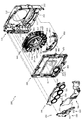
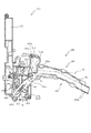
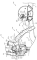
次いで、図5から図10を参照して、動作ユニット200の概略構成について説明する。図5は、動作ユニット200の分解正面斜視図であり、図6は、遊技盤13及び動作ユニット200の正面斜視図である。また、図7は、動作ユニット200の正面斜視図であり、図8から図10は、動作ユニット200の正面図である。   Next, a schematic configuration of the operation unit 200 will be described with reference to FIGS. FIG. 5 is an exploded front perspective view of the operation unit 200, and FIG. 6 is a front perspective view of the game board 13 and the operation unit 200. FIG. 7 is a front perspective view of the operation unit 200, and FIGS. 8 to 10 are front views of the operation unit 200.

なお、図6及び図7では、液晶昇降ユニット400が下降位置に配置された状態が、図9では、液晶昇降ユニット400の第2通路形成部材422と左揺動ユニット500の第1通路形成部材520とが連結された状態が、図10では、液晶昇降ユニット600が上昇位置に配置された状態が、それぞれ図示される。また、図6から図10では、上部昇降ユニット300が上昇位置に配置された状態が図示される。   6 and 7, the state where the liquid crystal lifting / lowering unit 400 is disposed at the lowered position is shown in FIG. 9. In FIG. 9, the second path forming member 422 of the liquid crystal lifting / lowering unit 400 and the first path forming member of the left swinging unit 500. FIG. 10 illustrates a state in which the liquid crystal lifting / lowering unit 600 is disposed at the raised position. 6 to 10 show a state in which the upper elevating unit 300 is disposed at the raised position.

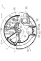
図5から図10に示すように、動作ユニット200は、箱状に形成される背面ケース210を備え、その背面ケース210の内部空間に、上部昇降ユニット300、液晶昇降ユニット400、左揺動ユニット500、回転ユニット600及び発光装飾部材700がそれぞれ収容される。   As shown in FIGS. 5 to 10, the operation unit 200 includes a rear case 210 formed in a box shape, and an upper elevating unit 300, a liquid crystal elevating unit 400, and a left swing unit are provided in the inner space of the rear case 210. 500, the rotation unit 600, and the light emitting decorative member 700 are accommodated.

背面ケース210は、正面視略矩形の底壁部211と、その底壁部211の4辺の外縁から正面へ向けて立設される外壁部212とを備え、これら各壁部211,212により一面側が開放された箱状に形成される。背面ケース210の底壁部211には、その中央に正面性略円形の凹部が凹設され、その凹部に回転ユニット600が収納される。液晶昇降ユニット400は、回転ユニット600の正面側に配設され、上部昇降ユニット300、左揺動ユニット500及び装飾発光部材700は、液晶昇降ユニット400の上側縁部、左側縁部および下側縁部にそれぞれ配設される。   The back case 210 includes a bottom wall portion 211 having a substantially rectangular shape when viewed from the front, and an outer wall portion 212 erected from the outer edges of the four sides of the bottom wall portion 211 toward the front. It is formed in a box shape with one side open. The bottom wall portion 211 of the back case 210 is provided with a concave portion having a frontal substantially circular shape at the center thereof, and the rotating unit 600 is accommodated in the concave portion. The liquid crystal lifting / lowering unit 400 is disposed on the front side of the rotating unit 600, and the upper lifting / lowering unit 300, the left swing unit 500 and the decorative light emitting member 700 are the upper edge, left side edge and lower side edge of the liquid crystal lifting / lowering unit 400. It is arranged in each part.

上部昇降ユニット300は、複数(本実施形態では4個)が幅方向(図8左右方向)に並設される昇降体330を備え、それら昇降体330がそれぞれ独立して高さ方向(図8上下方向)に昇降可能に形成される(図12及び図13参照)。液晶昇降ユニット400が下降位置に配置された状態では、昇降体330が上昇位置に配置されると、第3図柄表示装置81のほぼ全面が視認可能とされる一方(図8参照)、昇降体330が下降位置に配置されると(図12参照)、かかる昇降体330により第3図柄表示装置81の一部が視認不能とされる。   The upper lifting unit 300 includes a lifting body 330 in which a plurality (four in this embodiment) are juxtaposed in the width direction (left and right direction in FIG. 8), and these lifting bodies 330 are independently in the height direction (FIG. 8). It is formed to be movable up and down (refer to FIGS. 12 and 13). In the state where the liquid crystal lifting / lowering unit 400 is disposed at the lowered position, when the lifting / lowering body 330 is disposed at the raised position, almost the entire surface of the third symbol display device 81 can be visually recognized (see FIG. 8). When 330 is placed in the lowered position (see FIG. 12), a part of the third symbol display device 81 is made invisible by the elevating body 330.

液晶昇降ユニット400は、軸を上下方向に沿わせた縦姿勢で配設されると共に幅方向に所定間隔を隔てて配設される一対の案内棒451と、その案内棒451に幅方向両端がスライド変位可能に支持される駆動側スライド部材420及び従動側スライド部材430と、駆動側スライド部材420を昇降駆動する駆動モータ441とを備え、その駆動モータ441により駆動側スライド部材420が昇降駆動されることで、従動側スライド部材430が従動して昇降される。   The liquid crystal lifting / lowering unit 400 is arranged in a vertical posture with its axis along the vertical direction and a pair of guide rods 451 arranged at a predetermined interval in the width direction, and both ends in the width direction of the guide rod 451 are arranged. A drive side slide member 420 and a driven side slide member 430 supported so as to be slidable are provided, and a drive motor 441 that drives the drive side slide member 420 to move up and down. The drive motor 441 drives the drive side slide member 420 up and down. As a result, the driven-side slide member 430 is moved up and down.

即ち、駆動側スライド部材420が上昇される際には、かかる駆動側スライド部材420が従動側スライド部材430を重力の作用に抗しつつ上方へ押し上げる一方、駆動側スライド部材420が下降される際には、その駆動側スライド部材420の下降に伴い、従動側スライド部材430が自重により下降される。   That is, when the drive side slide member 420 is raised, the drive side slide member 420 pushes the driven side slide member 430 upward against the action of gravity, while the drive side slide member 420 is lowered. As the drive side slide member 420 is lowered, the driven side slide member 430 is lowered by its own weight.

なお、駆動側スライド部材420には、第2通路形成部材422が配設され、従動側スライド部材430には、第3図側表示装置81が配設される。駆動側スライド部材420が、上昇位置および下降位置の間の連結位置に配置されると、第2通路形成部材422が左揺動ユニット500の第1通路形成部材520と連結可能とされる(図9参照)。また、駆動側スライド部材420が、上昇位置に配置されると、第3図柄表示装置81の上方領域が上部昇降ユニット300の背面側に配置される(図10参照)。   The drive side slide member 420 is provided with a second passage forming member 422, and the driven side slide member 430 is provided with a FIG. 3 side display device 81. When the drive-side slide member 420 is disposed at the connecting position between the raised position and the lowered position, the second passage forming member 422 can be connected to the first passage forming member 520 of the left swing unit 500 (see FIG. 9). Further, when the drive side slide member 420 is disposed at the raised position, the upper region of the third symbol display device 81 is disposed on the back side of the upper lift unit 300 (see FIG. 10).

左揺動ユニット500は、基端側を中心として先端側を上下させる方向へ揺動される第1通路形成部材520を備える。第1通路形成部材520は、先端側を持ち上げる方向へ揺動されると、連結位置に配置され(図9参照)、先端側が液晶昇降ユニット400の第2通路形成部材422に連結される一方、先端側を振り下げる方向へ揺動されると、解除位置に配置され(図10参照)、液晶昇降ユニット400の第2通路形成部材422との連結が解除される。   The left swing unit 500 includes a first passage forming member 520 that is swung in a direction in which the distal end side is moved up and down around the base end side. When the first passage forming member 520 is swung in the direction of lifting the tip end side, the first passage forming member 520 is disposed at the connecting position (see FIG. 9), and the tip end side is connected to the second passage forming member 422 of the liquid crystal lifting / lowering unit 400, When it is swung in the direction in which the tip side is swung down, it is disposed at the release position (see FIG. 10), and the connection with the second passage forming member 422 of the liquid crystal lifting unit 400 is released.

遊技領域を流下する球は、左揺動ユニット500内へ流入可能とされ、左揺動ユニット500は、第1通路形成部材520が連結位置に配置された状態では(図9参照)、流入された球を、第1通路形成部材520を介して、液晶昇降ユニット400の第2通路形成部材422へ送球する一方、第1通路形成部材520が解除位置に配置された状態では(図10参照)、流入された球を、第1通路形成部材520とは別に設けられた後述する通路を介して、遊技領域へ送球する。   The sphere flowing down the game area can flow into the left swing unit 500, and the left swing unit 500 flows in when the first passage forming member 520 is disposed at the connection position (see FIG. 9). The ball is sent to the second passage forming member 422 of the liquid crystal lifting / lowering unit 400 via the first passage forming member 520, while the first passage forming member 520 is disposed at the release position (see FIG. 10). Then, the ball that has flowed in is sent to the game area through a passage, which will be described later, provided separately from the first passage formation member 520.

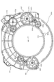
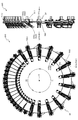
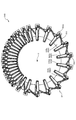
回転ユニット600は、ルーレットを模して構成される演出装置である。即ち、回転可能に形成されるホイール(回転盤)に相当する部材(回転部材640)と、そのホイールを周方向に区画して形成され赤または黒の色が付されると共にそれぞれ異なる数字が表示されるポケットに相当する部分(表示板646及び区画板647)とを備え、ホイールの内周側の装置(投球装置650)から投球された球Bが、複数のポケットに相当する部分のうちのいずれかに落下するように形成される。   The rotation unit 600 is an effect device configured to simulate a roulette. In other words, a member (rotating member 640) corresponding to a wheel (rotary disk) formed to be rotatable, and the wheel is formed by dividing the wheel in the circumferential direction, and a red or black color is given and a different number is displayed. A portion corresponding to the pocket (display plate 646 and partition plate 647), and the ball B thrown from the device (throwing device 650) on the inner peripheral side of the wheel is a portion of the portion corresponding to the plurality of pockets It is formed to fall on either.

液晶昇降ユニット400が下降位置に配置された状態では(図8参照)、回転ユニット600のほぼ全体が液晶昇降ユニット400によって遊技者から視認不能に遮蔽される一方、液晶昇降ユニット400が連結位置に配置された状態では(図9参照)、ホイールに相当する部材の一部(下方部分)が露出されると共に、液晶昇降ユニット400が上昇位置に配置された状態では(図10参照)、ホイールに相当する部材の一部(下方部分)に加え、ホイールに相当する部材の内周側に保持されている球B及びその球Bが投球されてからポケットに相当する部分に落下するまでの経路が露出され、これらが遊技者から視認可能とされる。   In a state where the liquid crystal lifting / lowering unit 400 is disposed at the lowered position (see FIG. 8), almost the entire rotating unit 600 is shielded from being visible to the player by the liquid crystal lifting / lowering unit 400, while the liquid crystal lifting / lowering unit 400 is at the connected position. In the disposed state (see FIG. 9), a part of the member corresponding to the wheel (lower part) is exposed, and in the state in which the liquid crystal lifting unit 400 is disposed in the raised position (see FIG. 10), In addition to a part (lower part) of the corresponding member, there is a path from the ball B held on the inner peripheral side of the member corresponding to the wheel to the part corresponding to the pocket after the ball B is thrown. These are exposed and are visible to the player.

発光装飾部材700は、光透過性の材料から形成されるケース体と、そのケース体の内部に配設される複数のLEDとを備え、LEDから発光する光の態様(例えば、発光するLEDの数や発光時間)を変更することで、発光による演出を行う。   The light emitting decoration member 700 includes a case body formed of a light-transmitting material and a plurality of LEDs disposed in the case body, and a mode of light emitted from the LEDs (for example, an LED of a light emitting LED). By changing the number and the light emission time, an effect by light emission is performed.

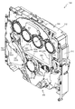
次いで、図11から図20を参照して、上部昇降ユニット300、液晶昇降ユニット400、左揺動ユニット500、回転ユニット600及び発光装飾部材700の詳細構成を説明する。まず、図11から図20を参照して、上部昇降ユニット300について説明する。   Next, with reference to FIGS. 11 to 20, detailed configurations of the upper elevating / lowering unit 300, the liquid crystal elevating / lowering unit 400, the left swing unit 500, the rotating unit 600 and the light emitting decorative member 700 will be described. First, the upper lift unit 300 will be described with reference to FIGS.

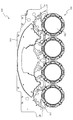
図11は、上部昇降ユニット300の正面斜視図であり、図12及び図13は、上部昇降ユニット300の正面図である。なお、図11及び図12では、幅方向(図12左右方向)に並設される全ての昇降体330が上昇位置に配置された状態が図示され、図13では、全ての昇降体330が下降位置に配置された状態が図示される。   FIG. 11 is a front perspective view of the upper lifting unit 300, and FIGS. 12 and 13 are front views of the upper lifting unit 300. 11 and 12 show a state in which all the lifting bodies 330 arranged in parallel in the width direction (left and right direction in FIG. 12) are arranged at the raised position, and in FIG. 13, all the lifting bodies 330 are lowered. The state of being placed in position is shown.

図11から図13に示すように、上部昇降ユニット300は、横長矩形板形状のベース部材310の幅方向に昇降体330が複数(本実施形態では4個)配設され、各昇降体330が上昇位置(図12参照)と下降位置(図13参照)との間を昇降移動可能に構成される。次いで、図14及び図15を参照して、各昇降体330の駆動機構の構成について説明する。   As shown in FIGS. 11 to 13, the upper elevating unit 300 includes a plurality of elevating bodies 330 (four in the present embodiment) arranged in the width direction of the horizontally long rectangular plate-shaped base member 310, and each elevating body 330 is configured as follows. It is configured to be movable up and down between an ascending position (see FIG. 12) and a descending position (see FIG. 13). Next, with reference to FIG. 14 and FIG. 15, the configuration of the drive mechanism of each lifting body 330 will be described.

図14は、上部昇降ユニット300の正面分解斜視図であり、図15は、上部昇降ユニット300の背面分解斜視図である。   FIG. 14 is a front exploded perspective view of the upper lift unit 300, and FIG. 15 is a rear exploded perspective view of the upper lift unit 300.

図14及び図15に図示されるように、上部昇降ユニット300は、横長矩形板形状のベース部材310と、そのベース部材310との間に伝達装置350を収容する空間を設けながらベース部材310の背面側に締結固定される背面カバー320と、ベース部材310及び背面カバー320の間にラック332が収容されると共に円形の演出部331がベース部材310の正面側に配置される昇降体330と、背面カバー部材320に締結固定され昇降体の昇降動作に必要な駆動力を発生させる駆動装置340と、その駆動装置340が発生する駆動力を昇降体330に伝達させる伝達装置350と、を主に備える。   As shown in FIGS. 14 and 15, the upper elevating unit 300 includes a base member 310 having a horizontally long rectangular plate shape and a space for housing the transmission device 350 between the base member 310 and the base member 310. A back cover 320 fastened and fixed to the back side, a lifting body 330 in which a rack 332 is accommodated between the base member 310 and the back cover 320 and a circular effect portion 331 is disposed on the front side of the base member 310; A driving device 340 that is fastened and fixed to the back cover member 320 and generates a driving force necessary for the lifting operation of the lifting body, and a transmission device 350 that transmits the driving force generated by the driving device 340 to the lifting body 330 are mainly used. Prepare.

カバー部材310は、下端に円の中心が配置される半円形状で正面側側面から背面側へ向けて凹設される半円凹設部311と、背面側側面から昇降体330のラック332の左右方向に若干隙間を空けた位置へ向かってリブ状に凸設される案内リブ312と、を備える。   The cover member 310 has a semicircular shape in which the center of a circle is disposed at the lower end and is recessed from the front side surface toward the back side. The cover member 310 includes a rack 332 of the elevator 330 from the back side surface. And a guide rib 312 protruding in a rib shape toward a position with a slight gap in the left-right direction.

半円凹設部311は、昇降体320の演出部331の外径よりも若干大きな半径で構成され、その半円凹設部311の円の中心と、演出部331の中心とが鉛直線状で一致する位置に配置される。これにより、演出部331が上昇移動する際に、ベース部材310の正面側において半円凹設部311と干渉する位置の手前まで移動することが可能となり、ベース部材310の上下幅は確保しつつ、演出部331の上昇移動幅も大きく確保することができる。   The semicircular recessed portion 311 is configured with a radius slightly larger than the outer diameter of the effect portion 331 of the elevating body 320, and the center of the circle of the semicircular recessed portion 311 and the center of the effect portion 331 are vertically linear. Are placed at the matching positions. Thereby, when the effect part 331 moves upward, it can be moved to a position just before the position where it interferes with the semicircular recessed part 311 on the front side of the base member 310, and the vertical width of the base member 310 is secured. In addition, the ascending movement width of the effect section 331 can be ensured to be large.

案内リブ部312は、鉛直方向に延びるリブ状の部分であって、組立状態(図11参照)において、昇降体330のラック332の左右側面と当接可能な位置まで凸設される。これにより、昇降体330が昇降移動中に左右方向に移動する(並行移動や傾斜動作する)ことを抑制することができる。   The guide rib portion 312 is a rib-like portion extending in the vertical direction, and protrudes to a position where it can come into contact with the left and right side surfaces of the rack 332 of the elevating body 330 in the assembled state (see FIG. 11). Thereby, it can suppress that the raising / lowering body 330 moves to the left-right direction during a raising / lowering movement (a parallel movement or inclination operation | movement).

また、半円凹設部311を正面側から背面側へ凹設される凹部として構成することで、前後方向に貫通する空間とする場合に比較して、背面側を視認不能とできる面積を広げることができる。従って、機構部分(ギアやモータ等の、遊技者に視認させることを目的としない部分)を配設する面積を大きく確保できる。   In addition, by configuring the semicircular recessed portion 311 as a recessed portion that is recessed from the front side to the back side, the area where the back side can be made invisible is widened as compared to a case where the space penetrates in the front-rear direction. be able to. Therefore, it is possible to secure a large area for disposing a mechanism portion (a portion such as a gear or a motor that is not intended to be visually recognized by the player).

背面カバー320は、正面側および下方が開放されたケース状に構成される本体部321と、その本体部321から正面側に凸設される円柱形状の軸支部322と、その軸支部322から正面視左右方向に位置ずれした位置において延設方向を鉛直方向と一致させた状態で穿設される長孔である案内孔323と、上側の軸支部322が凸設される周囲の底部から軸支部322の径方向に沿設されるリブ状に形成される係止部324と、を備える。   The back cover 320 includes a main body portion 321 configured in a case shape having an open front side and a lower side, a cylindrical shaft support portion 322 protruding from the main body portion 321 to the front side, and a front surface from the shaft support portion 322. A guide hole 323, which is a long hole drilled in a state in which the extending direction coincides with the vertical direction at a position displaced in the left-right direction, and a shaft support portion from the surrounding bottom portion where the upper shaft support portion 322 is projected. And a locking portion 324 formed in a rib shape along the radial direction of 322.

軸支部322は、伝達装置350の一対のギア部材351,352をそれぞれ軸支する部分であり、案内孔323は、昇降体330の昇降動作を案内する孔である。   The shaft support portion 322 is a portion that supports the pair of gear members 351 and 352 of the transmission device 350, and the guide hole 323 is a hole that guides the lifting operation of the lifting body 330.

係止部324は、上側の軸支部322の軸に対して、鉛直方向上側と鉛直方向下側とに配設され、それぞれ昇降体330が上昇位置または下降位置に配置された状態において、第1ギア351の係止円弧部351cの端部が回転方向で当接可能とされる部分である。   The locking portion 324 is disposed on the upper side in the vertical direction and the lower side in the vertical direction with respect to the axis of the upper shaft support portion 322, and in the state where the elevating body 330 is disposed at the raised position or the lowered position, respectively. The end of the locking arc portion 351c of the gear 351 is a portion that can be contacted in the rotation direction.

昇降体330は、円形板形状に構成される演出部331と、その演出部331の背面に固定され演出部331の背面側側面から隙間を空けた位置において鉛直方向に延設されるラック332と、を備える。   The elevating body 330 includes an effect portion 331 configured in a circular plate shape, and a rack 332 that is fixed to the back surface of the effect portion 331 and extends in the vertical direction at a position spaced from the rear side surface of the effect portion 331. .

演出部331は、円形の外枠の内側に円形の液晶パネルが配設され、液晶パネルに模様や図形を表示することにより演出を行う部分である。   The rendering unit 331 is a portion where a circular liquid crystal panel is disposed inside a circular outer frame, and a rendering is performed by displaying patterns and figures on the liquid crystal panel.

ラック332は、背面側に凸設されると共に背面カバー320の案内孔323に挿通される位置まで凸設されるスライド軸332aを備える。   The rack 332 includes a slide shaft 332 a that protrudes to the back side and protrudes to a position where the rack 332 is inserted into the guide hole 323 of the back cover 320.

スライド軸332aは、複数が凸設される態様ではなく、一つが凸設される態様とされる。そのため、案内孔323の配設個数を1つにでき(低減でき)るので、鉛直方向における案内孔323の配設スペースを抑制しながら、ラック332の移動距離を大きく確保することができる。一方で、本実施形態では、ラック332が左右方向で案内リブ部312と当接可能とされるので、ラック332の案内孔323との連結位置が一箇所であっても、ラック332が左右方向に傾くことを防止することができる。これにより、昇降体330が上下移動する際に演出部331が左右方向に振れることを防止できると共に、第2ギア352とラック332との間隔が変動して歯合関係が悪化することを防止することができる。   A plurality of slide shafts 332a are not provided in a projecting manner, but one is provided in a projecting manner. Therefore, since the number of guide holes 323 can be reduced to one (can be reduced), a large moving distance of the rack 332 can be secured while suppressing the space for arranging the guide holes 323 in the vertical direction. On the other hand, in the present embodiment, since the rack 332 can be brought into contact with the guide rib portion 312 in the left-right direction, the rack 332 can be moved in the left-right direction even if the rack 332 is connected to the guide hole 323 at one position. Can be prevented. Thereby, when the elevating body 330 moves up and down, the effect part 331 can be prevented from swinging in the left-right direction, and the gap between the second gear 352 and the rack 332 can be prevented from fluctuating and the meshing relationship can be prevented from deteriorating. be able to.

駆動装置340は、背面カバー320に締結固定される駆動源である駆動モータ341と、その駆動モータ341の駆動軸の回転により回転され伝達装置350に駆動力を伝達する駆動ギア342と、を備える。   The drive device 340 includes a drive motor 341 that is a drive source fastened and fixed to the back cover 320, and a drive gear 342 that is rotated by rotation of the drive shaft of the drive motor 341 and transmits a drive force to the transmission device 350. .

伝達装置350は、軸支部322に軸支されると共に駆動ギア342に歯合される第1ギア351と、その第1ギア351及びラック332に歯合されると共に軸支部322に軸支される第2ギア352と、を備える。   The transmission device 350 is supported by the shaft support 322 and meshed with the drive gear 342, and is meshed with the first gear 351 and the rack 332 and supported by the shaft support 322. A second gear 352.

このように、複数(本実施形態では4個)の昇降体330は、それぞれ独立の駆動モータ341を備えるので、全ての昇降体330が連動して昇降動作する動作に加え、各昇降体330を個別に昇降動作させることができる。なお、各昇降体330の技術的思想は共通するので、以下では、図11の左端に配設される昇降体330について説明し、その他の昇降体330についての説明を省略する。   As described above, the plurality (four in the present embodiment) of the lifting bodies 330 include the independent drive motors 341. Therefore, in addition to the operation in which all the lifting bodies 330 move up and down in conjunction, It can be moved up and down individually. In addition, since the technical idea of each raising / lowering body 330 is common, below, the raising / lowering body 330 arrange | positioned at the left end of FIG. 11 is demonstrated, and description about the other raising / lowering body 330 is abbreviate | omitted.

次いで、図16を参照して、第1ギア351及び第2ギア352について説明する。図16(a)は、第1ギア351の正面図であり、図16(b)は、第1ギア351の背面図であり、図16(c)は、第2ギア352の正面図であり、図16(d)は、第2ギア352の背面図である。   Next, the first gear 351 and the second gear 352 will be described with reference to FIG. 16 (a) is a front view of the first gear 351, FIG. 16 (b) is a rear view of the first gear 351, and FIG. 16 (c) is a front view of the second gear 352. FIG. 16D is a rear view of the second gear 352.

図16(a)及び図16(b)に示すように、第1ギア351は、軸支部322(図14参照)が挿通される貫通孔を備え外周面にギア歯が形成される本体部351aと、その本体部351aの外周面においてギア歯の形成が省略される部分にギア歯の歯丈の約半分の張出長さ(歯合する歯同士の接点を連結したピッチ円C1まで張り出す張出長さ)で径方向に張出形成される当接部351bと、本体部351aの背面側側面から軸と平行な方向に沿って軸を中心とした円弧形状で凸設される係止円弧部351cと、を備える。   As shown in FIGS. 16 (a) and 16 (b), the first gear 351 has a through hole through which the shaft support portion 322 (see FIG. 14) is inserted, and a main body portion 351a in which gear teeth are formed on the outer peripheral surface. And an extension length of about half of the tooth height of the gear teeth on the outer peripheral surface of the main body 351a (the pitch circle C1 connecting the contact points of the teeth to be engaged) Abutment portion 351b that is formed to project radially in the overhang length), and a latch that protrudes in an arc shape centering on the axis along the direction parallel to the axis from the back side surface of main body portion 351a Arc portion 351c.

当接部351bは、径方向の先端面が本体部351aの中心軸を中心として半径rの円弧形状とされ、およそ本体部351aに形成されるギア歯の2から3つ分の歯厚(円弧の中心の成す角度がおよそ45度から60度の範囲の歯厚)で構成される。即ち、ギア歯一つ分の歯厚よりも本体部351a周方向の形成長さが長くされるので、本体部351aのギア歯に比較して、周方向の強度を確保することができる。   The abutting portion 351b has an arc shape with a radius r centered on the central axis of the main body portion 351a, and a tooth thickness (arc) of about two to three gear teeth formed on the main body portion 351a. (The tooth thickness in the range of approximately 45 to 60 degrees). That is, since the formation length in the circumferential direction of the main body portion 351a is made longer than the tooth thickness of one gear tooth, the strength in the circumferential direction can be ensured as compared with the gear teeth of the main body portion 351a.

係止円弧部351cは、周方向の先端が背面カバー320の係止部324(図14参照)と周方向で当接可能とされる部分であって、第1ギア351の回転角度を規制する役割がある。   The locking arc portion 351c is a portion whose circumferential tip can be brought into contact with the locking portion 324 (see FIG. 14) of the back cover 320 in the circumferential direction, and regulates the rotation angle of the first gear 351. There is a role.

図16(c)及び図16(d)に示すように、第2ギア352は、正面側と背面側とで歯形の異なる2層のギアから構成され、ドーナツ板形状に構成される中間板353と、その中間板353の正面側に形成され歯形が一部異形とされる異形ギア部354と、中間板353の背面側に平歯車形状に形成されラック332(図15参照)と歯合される伝達ギア部355と、を備える。   As shown in FIG. 16C and FIG. 16D, the second gear 352 is composed of two layers of gears having different tooth shapes on the front side and the back side, and an intermediate plate 353 configured in a donut plate shape. And a deformed gear portion 354 formed on the front side of the intermediate plate 353 and having a partially deformed tooth shape, and a spur gear shape formed on the back side of the intermediate plate 353 and meshed with a rack 332 (see FIG. 15). Transmission gear portion 355.

中間板352は、異形ギア部354及び伝達ギア部355のギア歯の先端よりも径方向外側まで張り出して形成される。そのため、歯合される相手部材(第1ギア351又はラック332(図15参照))と歯面と平行な方向で重なることで当接可能とされ(図17参照)、その相手部材が昇降体330の昇降動作時に歯面と平行な方向へ移動することを抑制することができる。   The intermediate plate 352 is formed so as to protrude outward in the radial direction from the tips of the gear teeth of the deformed gear portion 354 and the transmission gear portion 355. Therefore, the mating member (the first gear 351 or the rack 332 (see FIG. 15)) can be brought into contact with each other by overlapping in the direction parallel to the tooth surface (see FIG. 17). It is possible to suppress movement in the direction parallel to the tooth surface during the elevating operation of 330.

異形ギア部354は、組立状態(図11参照)において第1ギア351と歯合される部分であって、軸支部322(図14参照)が挿通される貫通孔を備え外周面にギア歯が形成される本体部354aと、その本体部354aの外周面においてギア歯の形成が省略される部分に張出形成される受け部354bと、その受け部354bの一端(図16(c)右側の端部)に隣設される隣設ギア歯354cと、を備える。   The deformed gear portion 354 is a portion engaged with the first gear 351 in the assembled state (see FIG. 11), has a through hole through which the shaft support portion 322 (see FIG. 14) is inserted, and has gear teeth on the outer peripheral surface. A main body portion 354a to be formed, a receiving portion 354b that is formed to protrude from the outer peripheral surface of the main body portion 354a where gear teeth are not formed, and one end of the receiving portion 354b (on the right side of FIG. 16C) And adjacent gear teeth 354c provided adjacent to the end portion).

受け部354bは、本体部354aの外周面に沿って隣設ギア歯354cから正面視反時計回り側(昇降体330を上昇移動させる際に第1ギア351が隣設ギア部354cに噛み込む側)にギア歯2個分ほどの配設角度(約30度から50度)で形成される部分であって、伝達装置350が軸支部322に軸支された状態において当接部351bの先端面が形成する半径rの円弧形状に沿って湾曲形成される湾曲壁部354b1と、その湾曲壁部354b1と隣設ギア歯354cの周方向の歯面との間に隣設ギア歯354cの歯丈の約半分の歯丈(歯合する歯同士の接点を連結したピッチ円C2まで張り出される歯丈)で形成される連結壁部354b2と、を備える。従って、隣設ギア歯354cの連結壁部354b2側の側面は、隣設ギア歯354cの連結壁部354b2の反対側の側面の径方向の張出長さの約半分の張出長さで、連結壁部354b2と一体形成される状態で連結壁部354b2から径方向に張り出して構成される。   The receiving portion 354b is a counterclockwise front view from the adjacent gear teeth 354c along the outer peripheral surface of the main body portion 354a (the side on which the first gear 351 is engaged with the adjacent gear portion 354c when the elevating body 330 is moved upward) ) At a disposition angle of about two gear teeth (about 30 to 50 degrees), and the tip surface of the contact portion 351b in a state where the transmission device 350 is supported by the shaft support portion 322. Of the adjacent gear teeth 354c between the curved wall portion 354b1 and the circumferential tooth surface of the adjacent gear teeth 354c. , And a connecting wall portion 354b2 formed at a pitch circle extending to a pitch circle C2 in which the contacts of the teeth to be engaged are connected. Therefore, the side surface of the adjacent gear tooth 354c on the side of the connecting wall portion 354b2 is an overhang length that is about half the radial length of the side surface on the opposite side of the connecting wall portion 354b2 of the adjacent gear tooth 354c. In a state of being integrally formed with the connecting wall part 354b2, the connecting wall part 354b2 projects in the radial direction.

図16(c)に示すように、伝達装置350が軸支部322に軸支された状態において、第2ギア352が当接部351bの先端面が形成する半径rの円弧形状に沿って湾曲壁部354b1が配置される姿勢とされる場合に、隣設ギア歯354cは半径rの円弧の外側(第2ギア352側)に配置される態様とされる(隣設ギア歯354cが半径rの円と干渉しない位置での形成に留められる)。   As shown in FIG. 16C, in the state where the transmission device 350 is pivotally supported by the shaft support portion 322, the second gear 352 is curved along the arc shape with the radius r formed by the tip surface of the contact portion 351b. When the portion 354b1 is disposed, the adjacent gear tooth 354c is disposed outside the arc having the radius r (on the second gear 352 side) (the adjacent gear tooth 354c has the radius r). The formation is made at a position that does not interfere with the circle).

次いで、図17から図20を参照して、昇降体330の昇降動作について説明する。なお、上昇動作と下降動作との動作経路は共通であるので、ここでは上昇動作について説明し、下降動作の説明を省略する。   Next, the ascending / descending operation of the elevating body 330 will be described with reference to FIGS. 17 to 20. Since the ascending operation and the descending operation have the same operation path, the ascending operation will be described here, and the description of the descending operation will be omitted.

図17から図20は、昇降体330の上昇動作が時系列で図示される昇降体330及び伝達装置350の正面図である。なお、図17では、昇降体330が下降位置に配置された状態が図示され、図18では、図17に図示される状態から第2ギア352が正面視時計回りに回転され昇降体330が所定距離上昇動作し第1ギア351の当接部351bの周方向の端部が第2ギア352の隣設ギア歯354cに噛み合い始めた状態が図示され、図19では、図18に図示される状態から第1ギア351が正面視反時計回り及び第2ギア352が正面視時計回りに回転され当接部351bの周方向の端面と隣設ギア歯354cとの当接が外れた直後の状態が図示され、図20では、図19に図示される状態から第1ギア351のみが正面視時計回りに所定量回転された状態が図示される。   17 to 20 are front views of the lifting body 330 and the transmission device 350 in which the lifting operation of the lifting body 330 is illustrated in time series. 17 illustrates a state in which the lifting body 330 is disposed at the lowered position. In FIG. 18, the second gear 352 is rotated clockwise from the state illustrated in FIG. The state where the distance rising operation is started and the end portion in the circumferential direction of the contact portion 351b of the first gear 351 begins to engage with the adjacent gear teeth 354c of the second gear 352 is illustrated, and in FIG. 19, the state illustrated in FIG. The state immediately after the first gear 351 is rotated counterclockwise in the front view and the second gear 352 is rotated clockwise in the front view and the contact between the circumferential end surface of the contact portion 351b and the adjacent gear teeth 354c is released. FIG. 20 shows a state in which only the first gear 351 is rotated by a predetermined amount clockwise from the state shown in FIG.

図17から図20に図示されるように、昇降体330は、ラック332に駆動モータ341(図14参照)の駆動力が駆動ギア342及び伝達装置350を介して伝達されることにより昇降動作される。詳述すると、駆動ギア342の駆動力は、その駆動ギア342と歯合される第1ギア351から、その第1ギア351に歯合される第2ギア352の異形ギア部354に伝達され、第2ギア352の回転が、その第2ギア352の伝達ギア部355(図16(d)参照)と歯合されるラックに伝達されることにより、昇降体330が昇降動作する。   As shown in FIGS. 17 to 20, the elevating body 330 is moved up and down when the driving force of the drive motor 341 (see FIG. 14) is transmitted to the rack 332 via the drive gear 342 and the transmission device 350. The More specifically, the driving force of the drive gear 342 is transmitted from the first gear 351 meshed with the drive gear 342 to the deformed gear portion 354 of the second gear 352 meshed with the first gear 351, The rotation of the second gear 352 is transmitted to the rack meshed with the transmission gear portion 355 (see FIG. 16D) of the second gear 352, so that the lifting body 330 moves up and down.

図17に図示される下降位置では、ラック332のスライド軸322a(図15参照)が背面カバー320の案内孔323(図15参照)の下端に配置される。そのため、ラック332がそれ以上下方に移動することを機械的に防止できる。   In the lowered position shown in FIG. 17, the slide shaft 322 a (see FIG. 15) of the rack 332 is disposed at the lower end of the guide hole 323 (see FIG. 15) of the back cover 320. Therefore, it is possible to mechanically prevent the rack 332 from moving further downward.

また、図17に図示される状態において、第1ギア351の係止円弧部351cの周方向の端部と背面カバー320の下側の係止部324とが当接することで、第1ギア351の正面視時計回り方向(ラック332を下降動作させる方向)への回転が機械的に防止される。   In the state illustrated in FIG. 17, the first gear 351 is brought into contact with the circumferential end of the locking arc portion 351 c of the first gear 351 and the lower locking portion 324 of the back cover 320. Is rotated mechanically in the clockwise direction when viewed from the front (the direction in which the rack 332 is lowered).

これにより、駆動モータ341の制御不良などにより駆動ギア342が過回転して第1ギア351を図17に図示される状態から更に正面視時計間回りに回転させようとする負荷が生じたとしても、第1ギア351の回転が機械的に防止されることにより、その負荷が第2ギア352に伝達されることを防止でき、ラック332が下降動作する事態を回避できるので、スライド軸322a(図15参照)が案内孔323(図15参照)の下側面に押し当てられスライド軸322a又は案内孔323が破損することを防止することができる。   As a result, even if there is a load that causes the drive gear 342 to over-rotate due to poor control of the drive motor 341 and to rotate the first gear 351 further clockwise from the state shown in FIG. Since the rotation of the first gear 351 is mechanically prevented, the load can be prevented from being transmitted to the second gear 352, and the situation where the rack 332 is lowered can be avoided, so that the slide shaft 322a (see FIG. 15) is pressed against the lower surface of the guide hole 323 (see FIG. 15), and the slide shaft 322a or the guide hole 323 can be prevented from being damaged.

図18に図示されるように、昇降体330が上昇動作する過程において、周方向の歯厚が他のギア歯よりも大きくされる当接部351bの周方向端面が隣設ギア歯354cと噛み合うので、第2ギア352から第1ギア351へ逆方向に伝達される負荷(昇降体330の重さによる負荷)を他のギア歯に比較して強度の大きい当接部351bで受けることができ、第1ギア351の耐久性を向上させることができる。   As shown in FIG. 18, in the process in which the elevating body 330 moves upward, the circumferential end surface of the contact portion 351 b whose circumferential tooth thickness is larger than that of the other gear teeth meshes with the adjacent gear teeth 354 c. Therefore, a load transmitted in the reverse direction from the second gear 352 to the first gear 351 (a load due to the weight of the elevating body 330) can be received by the contact portion 351b having a higher strength than other gear teeth. The durability of the first gear 351 can be improved.

第1ギア351の当接部351bがピッチ円C1まで張り出されると共に、第2ギア352の連結壁部354b2がピッチ円C2まで張り出されるので、図18の状態において、当接部351bが連結壁部354b2と擦れる位置まで近接される。そのため、隣設ギア歯354cの歯元に近い部分で当接部351bと隣設ギア歯354cとを当接させることができ、隣設ギア歯354cの耐久性を向上させることができる。   Since the contact portion 351b of the first gear 351 extends to the pitch circle C1 and the connecting wall portion 354b2 of the second gear 352 extends to the pitch circle C2, the contact portion 351b is connected in the state of FIG. It approaches to the position which rubs with wall part 354b2. Therefore, the contact portion 351b and the adjacent gear tooth 354c can be brought into contact with each other at a portion close to the base of the adjacent gear tooth 354c, and the durability of the adjacent gear tooth 354c can be improved.

また、隣設ギア歯354cは、連結壁部354b2に周方向の一方の側面を連結されるので、他のギア歯に比較して、周方向から受ける負荷に対する強度が向上される。換言すれば、連結壁部354b2側の側面の径方向の張出長さが短くされるため、隣設ギア歯354cの歯丈方向と垂直な方向への変形に対する抵抗が増加すると共に、連結壁部354b2が隣設ギア歯354cと一体で形成されることで隣設ギア歯354cに負荷される力を受ける部分としての隣設ギア歯354c及び連結壁部354b2の合計の歯厚が大きくされるため、隣設ギア歯354cの周方向への変形に対する抵抗が増加する。これにより、隣設ギア歯354cが第1ギア351の当接部351bを受け止める際に破損することを抑制することができる。   Further, since the adjacent gear tooth 354c is connected to the connecting wall portion 354b2 on one side surface in the circumferential direction, the strength against the load received from the circumferential direction is improved as compared with the other gear teeth. In other words, since the overhang length in the radial direction of the side surface on the side of the connecting wall portion 354b2 is shortened, resistance to deformation of the adjacent gear teeth 354c in the direction perpendicular to the tooth height direction increases, and the connecting wall portion Since the 354b2 is formed integrally with the adjacent gear teeth 354c, the total tooth thickness of the adjacent gear teeth 354c and the connecting wall portion 354b2 as a portion receiving the force applied to the adjacent gear teeth 354c is increased. The resistance against the circumferential deformation of the adjacent gear teeth 354c increases. Thereby, it can suppress that the adjacent gear tooth 354c breaks when receiving the contact part 351b of the 1st gear 351.

図19に示すように、昇降体330が上昇位置に配置された直後の状態において、当接部351bの円弧状の先端部と隣設ギア歯354cとが当接する。この状態において、第1ギア351の周方向で第1ギア351と第2ギア352とが当接していないので、第1ギア351の回転方向の駆動力の第2ギア352への伝達が解除される。   As shown in FIG. 19, the arcuate tip of the abutting portion 351b and the adjacent gear teeth 354c abut in a state immediately after the elevating body 330 is disposed at the ascending position. In this state, since the first gear 351 and the second gear 352 are not in contact with each other in the circumferential direction of the first gear 351, transmission of the driving force in the rotational direction of the first gear 351 to the second gear 352 is released. The

そのため、第2ギア352に歯合される昇降体330の重さを支える力が第1ギア351から伝達されなくなり、昇降体330が落下する方向に移動しかけるので、第2ギア352がラック332を下降動作させる方向(図19反時計回り)に回転しかける。   Therefore, the force that supports the weight of the lifting body 330 meshed with the second gear 352 is not transmitted from the first gear 351, and the lifting body 330 starts to move in the falling direction, so that the second gear 352 moves the rack 332 down. Rotate in the direction to move downward (counterclockwise in FIG. 19).

一方で、図19に示すように、隣設ギア歯354cが回転する方向の範囲(隣設ギア歯354cの先端が形成する円の内側)に当接部351bが配置されるので、第2ギア352を回転させる際には、隣設ギア歯354cにより当接部351bを隣設ギア歯354cの移動軌跡の外側に押しやる必要がある。   On the other hand, as shown in FIG. 19, since the contact portion 351b is disposed in the range in the direction in which the adjacent gear teeth 354c rotate (inside the circle formed by the tip of the adjacent gear teeth 354c), the second gear When rotating 352, it is necessary to push the contact portion 351b to the outside of the movement locus of the adjacent gear teeth 354c by the adjacent gear teeth 354c.

当接部351bの外周形状が本体部351aの中心軸を中心とした円弧形状とされるので、当接部351bの外周面に与えられる荷重は、第1ギア351の軸側へ向かう軸方向成分Faと、第1ギア351の当接部351bの接線方向に沿う周方向成分Fbとに分解される。   Since the outer peripheral shape of the contact portion 351b is an arc shape centered on the central axis of the main body portion 351a, the load applied to the outer peripheral surface of the contact portion 351b is an axial component toward the axial side of the first gear 351. It is decomposed into Fa and a circumferential component Fb along the tangential direction of the contact portion 351b of the first gear 351.

軸方向成分Faは、第1ギア351を回転可能な方向では無く、また、第1ギア351の剛性が確保される状態では(径方向に伸縮しない構造では)、軸方向成分Faにより当接部351bを隣設ギア歯354cの移動軌跡の外側に押しやることは困難である。   The axial component Fa is not in a direction in which the first gear 351 can be rotated, and in a state where the rigidity of the first gear 351 is ensured (in a structure that does not expand and contract in the radial direction), the contact portion is caused by the axial component Fa. It is difficult to push 351b outside the movement locus of the adjacent gear teeth 354c.

周方向成分Fbは、第1ギア351の回転方向を向くが、隣設ギア歯354cと当接部351bとが点で接触するため、隣設ギア歯354cと当接部351bとの間で滑りが生じ、第1ギア351が回転されにくいため、周方向成分Fbにより当接部351bを隣設ギア歯354cの移動軌跡の外側に押しやることは困難である。   The circumferential component Fb is directed in the rotational direction of the first gear 351, but the adjacent gear teeth 354c and the contact portion 351b are in contact with each other at a point, and therefore slip between the adjacent gear teeth 354c and the contact portion 351b. Since the first gear 351 is difficult to rotate, it is difficult to push the contact portion 351b outside the movement locus of the adjacent gear teeth 354c by the circumferential component Fb.

従って、隣設ギア歯354cにより当接部351bを隣設ギア歯354cの移動軌跡の外側に押しやることが防止されることから、第2ギア352が回転することが防止され、第2ギア352及び昇降体330の状態が保持される。   Accordingly, the adjacent gear tooth 354c prevents the contact portion 351b from being pushed outside the movement locus of the adjacent gear tooth 354c, so that the second gear 352 is prevented from rotating, and the second gear 352 and The state of the elevating body 330 is maintained.

当接部351bと受け部354bの湾曲壁部354b1とが、共に第1ギア351を中心とした半径rの円弧形状から形成され、図19に図示されるように、第1回転ギア351の周方向に沿って面当たりで当接されるので、第1ギア351の回転を湾曲壁部354b1全体の面積を利用して強固に受け止めることができる。これにより、昇降体330が上昇位置に到達した後に駆動モータ341(図14参照)の停止が遅れたとしても、第1ギア351が過回転することを防止することができ、駆動モータ341の停止の遅れが昇降体330の動作態様に影響することを防止することができる。   The abutting portion 351b and the curved wall portion 354b1 of the receiving portion 354b are both formed in an arc shape with a radius r centering on the first gear 351, and as shown in FIG. 19, the circumference of the first rotating gear 351 is Since the contact is made per surface along the direction, the rotation of the first gear 351 can be firmly received using the entire area of the curved wall portion 354b1. Thereby, even if the stop of the drive motor 341 (see FIG. 14) is delayed after the elevating body 330 reaches the raised position, the first gear 351 can be prevented from over-rotating, and the drive motor 341 is stopped. Can be prevented from affecting the operation mode of the elevating body 330.

図20に示すように、第1ギア351は、係止円弧部351cが上側の係止部324に当接する状態まで回転し、停止する。図18から図20までの間、第1ギア351の当接部351bの周方向端面が隣設ギア歯354cの側面を押進することにより第2ギア352が回転されるので、隣設ギア歯354cが第2ギア352に対して位置合わせされ、図20に図示される状態において隣設ギア歯354cが当接部351bの歯先面に当接する状態を確実に形成することができる。   As shown in FIG. 20, the first gear 351 rotates and stops until the locking arc portion 351c comes into contact with the upper locking portion 324. 18 to 20, the circumferential end surface of the contact portion 351b of the first gear 351 pushes the side surface of the adjacent gear tooth 354c, so that the second gear 352 is rotated. 354c is aligned with the second gear 352, and in the state shown in FIG. 20, a state in which the adjacent gear tooth 354c abuts against the tooth tip surface of the abutting portion 351b can be reliably formed.

図19に示す状態から図20に示す状態までにおいて、昇降体330は上昇位置に配置されるので、第2ギア352がラック332を上昇移動させる方向(図20時計回り)に回転することが規制される。そのため、第1ギア351が第2ギア352に対して図19反時計回りに回転しても、第2ギア352が連れ回りすることが無い。従って、当接部351bの歯先面が隣設ギア歯354cに対面する状態を確実に形成することができる。   From the state shown in FIG. 19 to the state shown in FIG. 20, the elevating body 330 is disposed at the raised position, and therefore the second gear 352 is restricted from rotating in the direction in which the rack 332 is moved upward (clockwise in FIG. 20). Is done. Therefore, even if the first gear 351 rotates counterclockwise in FIG. 19 with respect to the second gear 352, the second gear 352 does not rotate. Therefore, it is possible to reliably form a state in which the tooth tip surface of the contact portion 351b faces the adjacent gear tooth 354c.

図20に図示されるように、昇降体330が上昇位置に配置された状態において、第2ギア352が当接部351bの先端面が形成する半径rの円弧形状に沿って湾曲壁部354b1が配置される姿勢とされ隣設ギア歯354cが半径rの円弧の外側(第2ギア352側)に配置されるので、図19に図示される状態から、第1ギア351のみを同一回転方向(図19反時計回り方向)に回転させることができる。   As shown in FIG. 20, the curved wall portion 354 b 1 has a curved wall portion 354 b 1 along the arc shape of the radius r formed by the tip surface of the contact portion 351 b in the state where the elevating body 330 is disposed at the raised position. Since the adjacent gear teeth 354c are arranged outside the circular arc having the radius r (on the second gear 352 side), only the first gear 351 is rotated in the same rotational direction (from the state shown in FIG. 19). It can be rotated in the counterclockwise direction of FIG.

このとき、当接部351bの歯厚が他のギア歯に比較して厚く(およそギア歯2個分から3個分の厚さ)されるので、第1ギア351の停止位置の精度を緩やかにすることができる。即ち、例えば、図19に示す状態から図20に示す状態の中間の位相に第1ギア351が停止したとしても、隣設ギア歯354cと当接部351bとの当接位置での関係は同様に確保され、第2ギア352の回転を規制することができる。   At this time, since the tooth thickness of the contact portion 351b is thicker than other gear teeth (approximately two to three gear teeth), the accuracy of the stop position of the first gear 351 is moderately increased. can do. That is, for example, even if the first gear 351 stops at an intermediate phase from the state shown in FIG. 19 to the state shown in FIG. 20, the relationship between the adjacent gear teeth 354c and the contact portion 351b is the same. The rotation of the second gear 352 can be restricted.

また、第1ギア351の停止位置の精度を緩やかにしたまま、第2ギア352の両方向への回転を規制することができる。即ち、第2ギア352が図20時計回りに回転しかけたとしても、受け部354bの湾曲壁部354b1が当接部351bの歯先面と当接することで、荷重の方向を詳細に上述した隣設ギア歯354cと当接部351bとの当接時と同様に第2ギア352の回転が規制される。従って、昇降体330が上昇位置に配置された状態においてラック332が上下両方向に移動する事が規制されるので、昇降体330にがたつきが発生することを抑制することができる。上下両方向の規制(特に、上昇方向の規制)は、従来のクランク機構で行うことは困難であり、本実施形態のように第1ギア351と第2ギア352のギア形状により、初めて達成されるものである。   Further, the rotation of the second gear 352 in both directions can be restricted while the accuracy of the stop position of the first gear 351 is moderated. That is, even if the second gear 352 rotates clockwise in FIG. 20, the curved wall portion 354b1 of the receiving portion 354b abuts against the tooth tip surface of the abutting portion 351b, so that the direction of the load is described in detail above. The rotation of the second gear 352 is restricted in the same manner as when the provided gear teeth 354c and the contact portion 351b are in contact. Therefore, since the rack 332 is restricted from moving in both the up and down directions in a state in which the elevating body 330 is disposed at the raised position, it is possible to suppress the occurrence of rattling in the elevating body 330. The restriction in both the upper and lower directions (particularly, the restriction in the upward direction) is difficult to be performed by the conventional crank mechanism, and is achieved for the first time by the gear shapes of the first gear 351 and the second gear 352 as in this embodiment. Is.

このように、第1ギア351及び第2ギア352の形状の関係により、昇降体330が上昇位置に配置された状態において第2ギア352が回転することを防止することができるので、昇降体330を上昇位置に維持するために駆動モータ341(図14参照)の駆動力を自重以上の大きさで付与し続けることを不要とでき、消費エネルギーを抑制することができる。   As described above, the shape of the first gear 351 and the second gear 352 can prevent the second gear 352 from rotating in a state in which the lifting body 330 is disposed at the raised position. Therefore, it is unnecessary to continuously apply the driving force of the drive motor 341 (see FIG. 14) with a magnitude greater than its own weight in order to maintain the lifted position in the raised position, and energy consumption can be suppressed.

また、クランク機構の死点を利用して昇降体330を上昇位置に維持することも可能ではあるが、その場合、昇降体330の移動距離に対応してクランク機構が大型化するという問題点があった。本実施形態では、クランク機構を不要とし、第1ギア351及び第2ギア352の形状の関係により第2ギア352の回転を規制できるので、伝達部分の小型化を図ることができる。   In addition, although it is possible to maintain the lifting body 330 at the raised position using the dead center of the crank mechanism, there is a problem that the crank mechanism increases in size in accordance with the moving distance of the lifting body 330. there were. In the present embodiment, a crank mechanism is not required, and the rotation of the second gear 352 can be restricted by the relationship between the shapes of the first gear 351 and the second gear 352, so the transmission portion can be reduced in size.

第2ギア352の回転の規制を解除する方法について説明する。図19及び図20に示す状態において、第1ギア351の当接部351bを逆方向へ回転させる場合の回転方向(図20時計回り方向)に当接部351bと干渉する別部材が配設されないので、第1ギア351の昇降体330を下降動作させる方向(図20時計回り方向)への回転動作が許容される。   A method for canceling the restriction on the rotation of the second gear 352 will be described. In the state shown in FIG. 19 and FIG. 20, another member that interferes with the contact portion 351b is not provided in the rotation direction (the clockwise direction in FIG. 20) when the contact portion 351b of the first gear 351 is rotated in the reverse direction. Therefore, the first gear 351 is allowed to rotate in the direction in which the elevating body 330 is lowered (the clockwise direction in FIG. 20).

第1ギア351を図20に図示される状態から図19に図示される状態まで回転させ、更に同一方向に回転させると第2ギア352の回転方向への規制が解除され(当接部351bの先端面が隣設ギア歯354cから離間して)、昇降体330が下降動作可能となる。即ち、第1ギア351の回転動作により、第2ギア352の回転規制の解除を行うことができ、第2ギア352の回転規制の解除のために第1ギア351に別動作を行わせることが不要であるので、第1ギア351の構造を簡素化することができる。   When the first gear 351 is rotated from the state shown in FIG. 20 to the state shown in FIG. 19 and further rotated in the same direction, the restriction in the rotational direction of the second gear 352 is released (the contact portion 351b When the distal end surface is separated from the adjacent gear teeth 354 c), the elevating body 330 can be lowered. That is, the rotation restriction of the second gear 352 can be released by the rotation operation of the first gear 351, and the first gear 351 can perform another operation to release the rotation restriction of the second gear 352. Since it is unnecessary, the structure of the first gear 351 can be simplified.

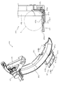
次いで、図21から図33を参照して、液晶昇降ユニット400について説明する。図21は、液晶昇降ユニット400の正面斜視図である。図21に示すように、液晶昇降ユニット400は、円形の液晶部分を有する演出部422aを有し昇降動作する駆動側スライド部材420と、その駆動側スライド部材420に従動して上昇動作する部材であって第3図柄表示装置81を備える従動側スライド部材430と、を備え、それら駆動側スライド部材420及び従動側スライド部材430が共通の案内棒451に連通され、同一方向に動作する態様で構成される。   Next, the liquid crystal lifting / lowering unit 400 will be described with reference to FIGS. FIG. 21 is a front perspective view of the liquid crystal lifting unit 400. As shown in FIG. 21, the liquid crystal lifting / lowering unit 400 includes a drive side slide member 420 that has a rendering portion 422 a having a circular liquid crystal portion and moves up and down, and a member that moves up and down following the drive side slide member 420. A driven-side slide member 430 having a third symbol display device 81, and the drive-side slide member 420 and the driven-side slide member 430 are connected to a common guide bar 451 and configured to operate in the same direction. Is done.

図22は、液晶昇降ユニット400の正面分解斜視図である。図22に図示されるように、液晶昇降ユニット400は、一対の長尺板状部材から構成されるベース部材410と、上下方向に昇降動作可能に構成される駆動側スライド部材420と、その駆動側スライド部材420の上方に配置され上下方向に動作可能に構成される従動側スライド部材430と、駆動側スライド部材420が昇降動作する駆動力を発生させる駆動装置440と、その駆動装置440から発生した駆動力を駆動側スライド部材420に伝達すると共に駆動側スライド部材420及び従動側スライド部材430の動作を案内する一対の案内棒451を有する伝達装置450と、一対のベース部材410の下端部同士を連結すると共に駆動側スライド部材420と連結される下側前板部材460と、液晶昇降ユニット400の左右および上部の正面側に配設されるカバー部材470と、を主に備えて構成される。   FIG. 22 is a front exploded perspective view of the liquid crystal lifting unit 400. As shown in FIG. 22, the liquid crystal lifting / lowering unit 400 includes a base member 410 composed of a pair of long plate-shaped members, a drive-side slide member 420 configured to be movable up and down in the vertical direction, and driving thereof. A driven slide member 430 that is arranged above the side slide member 420 and configured to be movable in the vertical direction, a drive device 440 that generates a drive force for the drive side slide member 420 to move up and down, and generated from the drive device 440 The transmission device 450 having a pair of guide rods 451 for transmitting the drive force to the drive side slide member 420 and guiding the operations of the drive side slide member 420 and the driven side slide member 430, and the lower ends of the pair of base members 410 And the lower front plate member 460 connected to the drive side slide member 420 and the left side of the liquid crystal lifting unit 400 And a cover member 470 which is disposed on the front side of the upper, and mainly includes a.

ベース部材410は、縦長の長尺板状部材として構成される本体部材411と、その本体部材411の上下両端部に互いに鉛直方向で一致する位置に配置され正面に開放するコ字形状の凹部として構成される案内棒支持部412と、その案内棒支持部412から引かれる鉛直線よりも内側(他方のベース部材410に近接する側)に配置され本体部材411の正面側に延設される係止部413と、案内棒支持部412から引かれる鉛直線を挟んで係止部413の反対側において本体部材411の正面側に円柱形状に凸設される第1軸支部414と、その第1軸支部414に軸支されると共に駆動側スライド部材420の下降動作を規制する下降規制部材415と、第1軸支部414の下方に配置され本体部材411の正面側に円柱形状に凸設される第2軸支部416と、その第2軸支部416に軸支されると共に従動側スライド部材430の上昇動作を規制する上昇規制部材417と、を主に備える。   The base member 410 is a main body member 411 configured as a vertically long plate-like member, and a U-shaped concave portion that is disposed at a position that coincides with the upper and lower ends of the main body member 411 in the vertical direction and opens to the front. A guide rod support portion 412 that is configured, and a member that is arranged on the inner side (side closer to the other base member 410) than the vertical line drawn from the guide rod support portion 412 and extends to the front side of the main body member 411. A first shaft support portion 414 that protrudes in a cylindrical shape on the front side of the main body member 411 on the opposite side of the locking portion 413 across the vertical line drawn from the stop portion 413, the guide rod support portion 412, and the first A downward regulating member 415 that is pivotally supported by the pivotal support portion 414 and restricts the downward movement of the drive side slide member 420, and is arranged below the first pivotal support portion 414 and protrudes in a cylindrical shape on the front side of the main body member 411. A second shaft support 416, the elevation regulating member 417 for regulating the upward movement of the driven sliding member 430 while being axially supported on the second shaft support portion 416 mainly comprises a.

案内棒支持部412は、伝達装置450の案内棒451の両端を支持する部分であって、案内棒451を収容可能な開口幅で形成される。本実施形態では、カバー部材470がベース部材410に締結固定されることにより、案内棒支持部412の正面側の開口が塞がれ、案内棒451が案内棒支持部412に固定される。   The guide rod support portion 412 is a portion that supports both ends of the guide rod 451 of the transmission device 450 and is formed with an opening width that can accommodate the guide rod 451. In this embodiment, when the cover member 470 is fastened and fixed to the base member 410, the opening on the front side of the guide rod support portion 412 is closed, and the guide rod 451 is fixed to the guide rod support portion 412.

係止部413は、従動側スライド部材430の落下防止部435の下側側面に上下方向で当接する部分であって、その当接状態から、それ以上、従動側スライド部材430が下降動作することを規制する。   The locking portion 413 is a portion that vertically contacts the lower side surface of the fall preventing portion 435 of the driven side slide member 430, and the driven side slide member 430 is further lowered from the contact state. To regulate.

下降規制部材415及び上昇規制部材417は、駆動側スライド部材420の昇降動作に伴って回転動作し、従動側スライド部材430の移動を規制する役割をもつ部材であるが、詳細は後述する。   The descending restricting member 415 and the ascending restricting member 417 are members that rotate as the drive-side slide member 420 moves up and down and have a role of restricting the movement of the driven-side slide member 430, and will be described in detail later.

駆動側スライド部材420は、左右両端部を伝達装置450のラック452に締結固定され、ラック452のスライド動作により昇降動作される部材である。   The drive-side slide member 420 is a member that is fastened and fixed to the rack 452 of the transmission device 450 at both left and right ends, and is moved up and down by a slide operation of the rack 452.

従動側スライド部材430は、独立の駆動装置を持たず、左右両端を案内棒451にスライド動作可能に支持されると共に、駆動側スライド部材420の昇降動作に従動して昇降動作する。従動側スライド部材430は、第3図柄表示装置81を有し左右方向に長尺に構成される本体部材431と、その本体部材431の左右方向両端に配置される機能部432と、その機能部432に鉛直方向に穿設される孔であって案内棒451が挿通される案内孔433と、機能部432の下端部において左右外側方向に上昇傾斜して延設される鉤状部434と、機能部432の上端部の案内孔433の内側(他方の案内孔433に近接する側)において背面側に延設される落下防止部435と、を主に備える。   The driven-side slide member 430 does not have an independent driving device, and is supported by the guide rods 451 so that the left and right ends can slide. In addition, the driven-side slide member 430 moves up and down following the up-and-down operation of the drive-side slide member 420. The driven-side slide member 430 includes a main body member 431 that has the third symbol display device 81 and is elongated in the left-right direction, a function unit 432 that is disposed at both ends of the main body member 431 in the left-right direction, and a function unit thereof A guide hole 433 which is a hole drilled in the vertical direction in 432 and through which the guide rod 451 is inserted, and a hook-like part 434 which is extended and inclined in the laterally outward direction at the lower end of the functional part 432, The fall prevention part 435 extended mainly in the back side inside the guide hole 433 of the upper end part of the function part 432 (side adjacent to the other guide hole 433) is mainly provided.

鉤状部434は、上昇規制部材417に引っ掛けられる部分である。従動側スライド部材430が下降位置に配置される状態において、上昇規制部材417が鉤状部434の上側面である係合面434aに回り込んで引っ掛けられることで(図29参照)、従動側スライド部材430が上昇方向に動作することを防止することができる(例えば、落下の反動で跳ねることを防止することができる)。また、鉤状部434が上昇傾斜し、その傾斜と平行に上昇規制部材417の係合爪部417eが構成されるので、鉤状部434と上昇規制部材417との係合により、左右方向のぐらつきも抑制することができる。   The hook-shaped portion 434 is a portion that is hooked by the rise restricting member 417. In the state where the driven side slide member 430 is disposed at the lowered position, the rise restricting member 417 wraps around and is hooked on the engagement surface 434a which is the upper side surface of the hook-shaped portion 434 (see FIG. 29), and the driven side slide. It is possible to prevent the member 430 from moving in the upward direction (for example, it is possible to prevent the member 430 from bouncing due to a drop reaction). Further, the hook-shaped portion 434 is inclined upward, and the engaging claw portion 417e of the upward restriction member 417 is formed in parallel with the inclination. Therefore, the engagement between the hook-shaped portion 434 and the upward restriction member 417 causes the left-right direction. Wobble can also be suppressed.

なお、鉤状部434の先端部(図29に図示される状態において係合爪部417eの先端部よりも外側(図29右側の部分))の形状は、係合爪部417eの移動軌跡よりも下方に収まる形状とされる。そのため、係合爪部417eと鉤状部434とが係合し、互いに負荷を掛け合う状態においても、上昇規制部材417の回転動作を行うことができる。   Note that the shape of the distal end portion of the hook-shaped portion 434 (the outer side of the distal end portion of the engaging claw portion 417e in the state shown in FIG. 29 (the portion on the right side in FIG. 29)) is based on the movement locus of the engaging claw portion 417e. Is also shaped to fit below. Therefore, even when the engaging claw portion 417e and the hook-like portion 434 are engaged and a load is applied to each other, the lifting restricting member 417 can be rotated.

駆動装置440は、ベース部材410の本体部材411に締結固定される駆動モータ441と、その駆動モータの駆動力で回転される駆動ギア442と、を備える。   The drive device 440 includes a drive motor 441 that is fastened and fixed to the main body member 411 of the base member 410, and a drive gear 442 that is rotated by the drive force of the drive motor.

伝達装置450は、ベース部材410の案内棒支持部412に固定される一対の案内棒451と、その案内棒451にスライド動作可能に支持され駆動側スライド部材420が締結固定されると共に駆動ギア442に内側(一対の駆動ギア442の内側)から歯合されるラック452とそのラック452の歯元付近から正面側に延設される縦長板状の当接壁453と、を主に備える。   The transmission device 450 includes a pair of guide rods 451 fixed to the guide rod support portion 412 of the base member 410, and is supported by the guide rods 451 so as to be slidable, and the drive side slide member 420 is fastened and fixed, and the drive gear 442. A rack 452 meshed from the inside (inside the pair of drive gears 442) and a vertically long plate-like contact wall 453 extending from the vicinity of the tooth base of the rack 452 to the front side are mainly provided.

当接壁453は、上昇規制部材417を解除側に回転させる役割と、上昇規制部材417の付勢力を受けてラック452を駆動ギア442から離反する方向に寄せる役割とを備えるが、詳細は後述する。   The abutting wall 453 has a role of rotating the ascending restriction member 417 to the release side and a role of moving the rack 452 away from the drive gear 442 by receiving the urging force of the ascending restriction member 417. The details will be described later. To do.

下側前板部材460は、左右端部はベース部材410の本体部材411の正面側に締結固定され中央部は左右端部に比較して背面側に所定量オフセットされる態様で折曲される形状の本体部材461と、その本体部材461の左半部において左右方向に沿って(外側に近接するほど上昇傾斜する態様で)穿設される案内孔462と、本体部材461の上方に延設される筒状部材であって上端部が正面側に開口される筒状通路部463と、を主に備える。   The lower front plate member 460 is bent in such a manner that the left and right end portions are fastened and fixed to the front side of the main body member 411 of the base member 410 and the center portion is offset by a predetermined amount on the back side compared to the left and right end portions. A main body member 461 having a shape, a guide hole 462 drilled along the left-right direction in the left half of the main body member 461 (in a manner of rising and tilting toward the outside), and extending above the main body member 461 And a cylindrical passage portion 463 whose upper end is opened to the front side.

案内孔462は、配線収納部材423のスライド軸423bがスライド可能に案内される長孔である。   The guide hole 462 is a long hole through which the slide shaft 423b of the wiring storage member 423 is slidably guided.

筒状通路部463は、球が通過可能な筒状の部材であって、駆動側スライド部材420が連結位置に配置される状態(図31参照)において、駆動側スライド部材420の第2通路形成部材422を通過して流下する球が通過する部材である。   The cylindrical passage portion 463 is a cylindrical member through which a sphere can pass, and the second passage formation of the drive side slide member 420 is performed in a state where the drive side slide member 420 is disposed at the coupling position (see FIG. 31). A sphere that passes through the member 422 and flows down passes therethrough.

図23から図25を参照して、駆動側スライド部材420の詳細構成について説明する。図23は、駆動側スライド部材420の分解正面斜視図であり、図24は、駆動側スライド部材420の分解背面斜視図であり、図25は、駆動側スライド部材420の背面図である。   With reference to FIGS. 23 to 25, a detailed configuration of the drive side slide member 420 will be described. 23 is an exploded front perspective view of the drive side slide member 420, FIG. 24 is an exploded rear perspective view of the drive side slide member 420, and FIG. 25 is a rear view of the drive side slide member 420.

図23から図25に図示されるように、駆動側スライド部材420は、左右方向に長尺な板状部材として構成される本体部材421と、円形の液晶から構成される演出部422aを有する円盤部分が本体部材421の中心部に正面側から締結固定されると共にその円盤部分から正面視左方に球が通過可能な溝が延設される第2通路形成部材422と、その第2流路形成部材422の正面視左下端部に一方の端部が軸支され他方の端部が下側前板部材460の案内孔462に支持される配線収納部材423と、第2流路形成部材422に軸支されると共に軸の周方向に沿って貫通する通路部を有し第2流路形成部材422の溝部422bへ球を導入する部分としてはたらく接続部材424と、を主に備える。   As shown in FIGS. 23 to 25, the drive-side slide member 420 is a disk having a main body member 421 configured as a plate-like member elongated in the left-right direction and an effect portion 422 a configured from a circular liquid crystal. A second passage forming member 422 whose portion is fastened and fixed to the central portion of the main body member 421 from the front side, and a groove through which a sphere can pass to the left in front view from the disk portion; A wiring housing member 423 whose one end is pivotally supported at the lower left end of the forming member 422 when viewed from the front and whose other end is supported by the guide hole 462 of the lower front plate member 460, and a second flow path forming member 422. And a connection member 424 that has a passage portion that is pivotally supported along the circumferential direction of the shaft and serves as a portion for introducing a sphere into the groove portion 422b of the second flow path forming member 422.

本体部材421は、案内棒451(図22参照)が挿通される筒状部の一部を構成する案内部421aと、中央部から正面視左方に延設される部分に正面側に開放する態様で左方に下降傾斜して配設される溝部421bと、その溝部421bの左下端部において球の直径以上の大きさで前後方向に貫通形成される排出開口部421cと、を主に備える。   The main body member 421 opens to the front side in a guide portion 421a that constitutes a part of a cylindrical portion through which the guide rod 451 (see FIG. 22) is inserted and a portion that extends from the center portion to the left in front view. And a discharge opening 421c formed to penetrate in the front-rear direction with a size equal to or larger than the diameter of the sphere at the lower left end of the groove 421b. .

案内部421aは、背面側に開放され鉛直方向に延設される断面円弧形状の溝部分であって、その開放部分を伝達装置450のラック452(図22参照)で閉鎖することにより、案内棒451(図22参照)が挿通される筒状部が構成される。   The guide portion 421a is a groove portion having an arc-shaped cross section that is open to the back side and extends in the vertical direction. The open portion is closed by a rack 452 (see FIG. 22) of the transmission device 450, thereby guiding the guide rod. A cylindrical portion into which 451 (see FIG. 22) is inserted is configured.

溝部421bは、第2通路形成部材422と共同で球の通路を形成する部材であって、溝部421bに沿って流下した球は、排出開口部421cを通って本体部材421の背面側へ排出される。   The groove portion 421b is a member that forms a spherical passage in cooperation with the second passage forming member 422, and the sphere flowing down along the groove portion 421b is discharged to the back side of the main body member 421 through the discharge opening 421c. The

第2通路形成部材422は、円形の液晶から構成される演出部422aと、その円形の液晶の背面側に配設される円盤部分から背面側へ円柱形状で凸設される軸支部422bと、その軸支部422bの下方に配設され球の通過を検出するセンサ部材422cと、そのセンサ部材422cを通過した球が流下可能な幅で背面側へ開放される溝であり溝部421bと前後方向で形状が一致する溝部422dと、案内棒451(図22参照)が挿通される筒状部を構成する案内部422eと、軸支部422bとセンサ部材422cとの間で接続部材424を収容可能な形状で凹設される収容凹部422fと、を主に備える。   The second passage forming member 422 includes an effect portion 422a composed of a circular liquid crystal, and a shaft support portion 422b that protrudes in a cylindrical shape from a disk portion disposed on the back side of the circular liquid crystal to the back side, A sensor member 422c that is disposed below the shaft support portion 422b and detects the passage of the sphere, and a groove that opens to the back side with a width that allows the sphere that has passed the sensor member 422c to flow down. A shape that can accommodate the connecting member 424 between the groove portion 422d having the same shape, the guide portion 422e constituting the cylindrical portion through which the guide rod 451 (see FIG. 22) is inserted, and the shaft support portion 422b and the sensor member 422c. And an accommodation recess 422f that is recessed.

軸支部422bは、接続部材424が軸支される部分である。連結位置に液晶昇降ユニット400が配置される状態において、左揺動ユニット500を流下した球が接続部材424を介してセンサ部材422cを通過したあと、溝部422d,421bの形成する通路を球が通過する。   The shaft support portion 422b is a portion on which the connection member 424 is supported. In a state where the liquid crystal lifting / lowering unit 400 is disposed at the coupling position, the sphere that has flowed down the left swing unit 500 passes through the sensor member 422c through the connection member 424, and then passes through the passage formed by the groove portions 422d and 421b. To do.

配線収納部材423は、下側前側部材460等から延長され演出部422a等に接続される配線を収容する部材であって、第2通路形成部材422の正面視左下端部に軸支される長尺断面コ字状の棒状部分である本体部423aと、その本体部423aの下端部から背面側に凸設される円柱形状のスライド軸423bと、を主に備える。   The wiring housing member 423 is a member that houses the wiring that is extended from the lower front member 460 and the like and connected to the effect portion 422a and the like, and is a length that is pivotally supported by the left lower end portion of the second passage forming member 422 when viewed from the front. A main body 423a that is a bar-shaped portion having a U-shaped cross section and a columnar slide shaft 423b that protrudes from the lower end of the main body 423a to the back side are mainly provided.

本体部423aは、断面コ字状に形成される内側部分に配線を収納する部材であって、長手方向に第2通路形成部材422から離反する方向に凸となる態様で湾曲した形状で構成される。これにより、第2通路形成部材422との軸支位置付近において、湾曲形状に沿って配線を弛ませることができ、配線が折れ曲げられて断線することを抑制することができる。   The main body portion 423a is a member that stores wiring in an inner portion formed in a U-shaped cross section, and is configured in a curved shape that is convex in a direction away from the second passage forming member 422 in the longitudinal direction. The Accordingly, the wiring can be loosened along the curved shape in the vicinity of the pivot support position with the second passage forming member 422, and the wiring can be prevented from being bent and disconnected.

スライド軸423bは、下側前板部材460の案内孔462に挿通される棒状部分である。   The slide shaft 423b is a bar-like portion that is inserted into the guide hole 462 of the lower front plate member 460.

次いで、図26を参照して、接続部材424の構成について説明する。図26(a)は、接続部材424の正面斜視図であり、図26(b)は、図26(a)の矢印XXVIb方向視における接続部材424の正面図であり、図26(c)は、図26(a)の矢印XXVIc方向視における接続部材424の背面図である。   Next, the configuration of the connection member 424 will be described with reference to FIG. 26A is a front perspective view of the connection member 424, FIG. 26B is a front view of the connection member 424 in the direction of arrow XXVIb in FIG. 26A, and FIG. FIG. 27 is a rear view of the connection member 424 when viewed in the direction of the arrow XXVIc in FIG.

図26(a)から図26(c)に示すように、接続部材424は、筒状に形成され軸支部422bに軸支される筒状部424aと、その筒状部424aの径方向に延設される板状の上側壁部424bと、その上側壁部424bの正面視下方に球の直径以上の長さを空けて上側壁部424bと対向配置される湾曲した板状の下側壁部424cと、それら上側壁部424b及び下側壁部424cの背面側端部を連結すると共に上側壁部424b及び下側壁部424cの間に覆設される連結カバー424dと、筒状部424aに巻き付けられ接続部材424に下向き(図25(b)反時計回り)の付勢力を与えるねじりバネ424eと、を主に備える。   As shown in FIGS. 26 (a) to 26 (c), the connecting member 424 is formed in a cylindrical shape and is supported in the radial direction of the cylindrical portion 424a. A plate-like upper side wall 424b provided, and a curved plate-like lower side wall 424c disposed opposite to the upper side wall 424b with a length equal to or larger than the diameter of the sphere below the upper side wall 424b when viewed from the front. Connecting the upper side wall 424b and the lower side wall 424c to the back side and connecting cover 424d, which is covered between the upper side wall 424b and the lower side wall 424c, and is wound around and connected to the cylindrical part 424a. And a torsion spring 424e that mainly applies a downward biasing force (counterclockwise in FIG. 25B) to the member 424.

上側壁部424bは、筒状部424aの径方向の端部から筒状部424aの軸へ近接する程幅が大きくなる態様で形成され側面が図25(b)において直線に沿って形成される板状部である。   The upper side wall portion 424b is formed in such a manner that the width increases as it approaches the axis of the tubular portion 424a from the radial end portion of the tubular portion 424a, and the side surface is formed along a straight line in FIG. It is a plate-like part.

下側壁部424cは、筒状部424aの軸を中心とした円弧に沿って湾曲形成される板状部であり、上側壁部424bとの間に球が通過可能な長さの空間を空けて配設される。   The lower wall portion 424c is a plate-like portion that is curved along an arc centering on the axis of the cylindrical portion 424a, and a space that allows a sphere to pass therethrough is provided between the lower wall portion 424c and the upper wall portion 424b. Arranged.

連結カバー424dは、接続部材424を通過する球が背面側にこぼれることを抑制する板部材である。なお、連結カバー424dの反対側(正面側)に構成される接続部材424の開放部は、第2通路形成部材422の収容凹部422fの底部が正面側から当接されることで塞がれる。これにより、球が接続部材424の開放部からこぼれることを抑制することができる。   The connection cover 424d is a plate member that suppresses spilling of a sphere passing through the connection member 424 to the back side. In addition, the open part of the connection member 424 configured on the opposite side (front side) of the connection cover 424d is closed by the bottom part of the housing recess 422f of the second passage forming member 422 coming into contact with the front side. Thereby, it can suppress that a ball | bowl spills from the open part of the connection member 424. FIG.

図27及び図28を参照して、第2通路形成部材422に対する接続部材424の動作について説明する。図27及び図28は、第2通路形成部材422及び接続部材424の背面図である。なお、図27では、接続部材424の上側壁部424b及び下側壁部424cにより構成される開放部が左右方向を向く下傾斜状態が図示され、図28では、図27の状態に比較して接続部材424の上側壁部424b及び下側壁部424cにより構成される開放部が斜め上方向を向く上傾斜状態が図示され、図27が後述する離間状態(図41参照)に対応し、図28が後述する連通状態(図42参照)に対応する。   With reference to FIGS. 27 and 28, the operation of the connecting member 424 with respect to the second passage forming member 422 will be described. 27 and 28 are rear views of the second passage forming member 422 and the connecting member 424. FIG. 27 shows a downwardly inclined state in which the open portion constituted by the upper wall portion 424b and the lower wall portion 424c of the connection member 424 faces the left-right direction, and in FIG. 28, the connection is made in comparison with the state of FIG. FIG. 27 corresponds to a separated state (see FIG. 41), which will be described later, and FIG. 28 corresponds to a separated state (see FIG. 41), in which an open portion constituted by the upper wall portion 424b and the lower wall portion 424c of the member 424 faces obliquely upward. This corresponds to a communication state (see FIG. 42) described later.

図27及び図28に示すように、接続部材424は、第2通路形成部材422の収容凹部422fに収容された状態で軸支部422bを中心に回転動作可能とされ、第2通路形成部材422の収容凹部422fの底部に上側壁部424b及び下側壁部424cの正面側端面が当接される。   As shown in FIGS. 27 and 28, the connection member 424 can rotate around the shaft support portion 422b while being accommodated in the accommodation recess 422f of the second passage formation member 422. The front side end surfaces of the upper side wall part 424b and the lower side wall part 424c are brought into contact with the bottom part of the housing recess 422f.

収容凹部422fは、図27に図示される状態で接続部材424の下側壁部424cと対向配置される部分に、下側壁部424cの外径に沿って軸支部422bを中心とした円弧形状に形成される湾曲壁部422f1と、その湾曲壁部422f1と対向配置される面が湾曲壁部422f1から遠ざかる方向に凹み上傾斜状態(図42参照)において接続部材424の上側壁部424bと滑らかに連結される湾曲面を有する対向壁部422f2と、を備える。   In the state shown in FIG. 27, the housing recess 422f is formed in an arc shape centered on the shaft support portion 422b along the outer diameter of the lower wall portion 424c in a portion opposed to the lower wall portion 424c of the connection member 424. The curved wall portion 422f1 and the surface opposed to the curved wall portion 422f1 are recessed in a direction away from the curved wall portion 422f1, and smoothly connected to the upper wall portion 424b of the connection member 424 in the inclined state (see FIG. 42). An opposing wall portion 422f2 having a curved surface.

湾曲壁部422f1は、接続部材424の下傾斜状態において下側壁部424cと径方向で面当たりされるので、接続部材424の軸径方向の位置ずれを抑制することができる。   Since the curved wall portion 422f1 is brought into contact with the lower wall portion 424c in the radial direction in the downwardly inclined state of the connecting member 424, the displacement of the connecting member 424 in the axial radial direction can be suppressed.

従って、軸支部422bと接続部材424の筒状部424aとの嵌合を緩め(隙間の大きい状態、例えば、寸法が0.5mmから1mmの間の隙間を有する状態)としたとしても、接続部材424が下傾斜状態とされる場合には下側壁部424cと湾曲壁部422f1との当接により、接続部材424の姿勢を高精度に維持することができる。   Therefore, even if the fitting between the shaft support portion 422b and the tubular portion 424a of the connection member 424 is loosened (a state where the gap is large, for example, a state where the dimension is between 0.5 mm and 1 mm), the connection member When 424 is in the downward inclined state, the posture of the connecting member 424 can be maintained with high accuracy by the contact between the lower wall portion 424c and the curved wall portion 422f1.

一方で、軸支部422bと接続部材424の筒状部424aとの嵌合を緩めとする場合、軸支部分に生じる動作抵抗が低減されるので、他の部材からの負荷が生じない限り、接続部材424を重力の作用およびねじりバネ424eの付勢力で確実に下傾斜状態に維持することができる。従って、他の部材からの負荷が生じていないのに、接続部材424が上傾斜状態に維持される事態を抑制する事ができる。   On the other hand, when loosening the fitting between the shaft support portion 422b and the cylindrical portion 424a of the connection member 424, since the operation resistance generated in the shaft support portion is reduced, the connection is made unless a load from other members occurs. The member 424 can be reliably maintained in the downward inclined state by the action of gravity and the biasing force of the torsion spring 424e. Accordingly, it is possible to suppress a situation in which the connection member 424 is maintained in the upwardly inclined state even when no load is generated from other members.

対向壁部422f2は、接続部材424からセンサ部材422cへ球を案内する部分である。本実施形態では、湾曲壁部422f1と対向配置する面が湾曲することにより、球を滑らかにセンサ部材422cへ案内することができる。   The opposing wall portion 422f2 is a portion that guides the sphere from the connection member 424 to the sensor member 422c. In the present embodiment, the surface facing the curved wall portion 422f1 is curved, so that the sphere can be smoothly guided to the sensor member 422c.

上傾斜状態は、左揺動ユニット500の第1通路形成部材520と接続部材424とが連通される連通状態において形成される。この状態では、下側壁部424cがセンサ部材422cの開口から離間されるので、接続部材424の下側壁部424cを転動して通過した球は湾曲壁部422f1を転動し、センサ部材422cの開口を通過して溝部422dを流下する。   The upward inclined state is formed in a communication state in which the first passage forming member 520 and the connection member 424 of the left swing unit 500 are communicated. In this state, since the lower wall portion 424c is separated from the opening of the sensor member 422c, the ball that rolls and passes through the lower wall portion 424c of the connection member 424 rolls on the curved wall portion 422f1, and the sensor member 422c Passing through the opening, it flows down the groove 422d.

一方、下傾斜状態は、左揺動ユニット500の第1通路形成部材520と接続部材424とが離間される離間状態において形成される。この状態では、下側壁部424cが、センサ部材422cの開口の内側まで張り出し、下側壁部422cの下側端部と、その下側端部と対向配置される収容凹部422fの壁面(センサ部材422cから鉛直上方に延びる壁面)との間の寸法が球の直径以下とされることで、球が接続部材424を通過する(球が下端部から排出される)ことが防止される。   On the other hand, the downward inclined state is formed in a separated state in which the first passage forming member 520 and the connecting member 424 of the left swing unit 500 are separated. In this state, the lower wall portion 424c extends to the inside of the opening of the sensor member 422c, and the lower end portion of the lower wall portion 422c and the wall surface (the sensor member 422c) of the housing recess 422f disposed to face the lower end portion. The dimension between the first wall and the wall surface extending vertically upward is equal to or less than the diameter of the sphere, so that the sphere is prevented from passing through the connecting member 424 (the sphere is discharged from the lower end).

そのため、後述するように、離間状態において球が接続部材424に到達したとしても、その球の流れを接続部材424で停滞させることができる。   Therefore, as described later, even when the sphere reaches the connection member 424 in the separated state, the flow of the sphere can be stopped by the connection member 424.

次いで、図29から図33を参照して、駆動側スライド部材420及び従動側スライド部材430の昇降動作について説明する。まず、図29及び図30を参照して駆動側スライド部材420、従動側スライド部材430及びベース部材410の位置関係を説明する。   Next, with reference to FIGS. 29 to 33, the raising and lowering operations of the drive side slide member 420 and the driven side slide member 430 will be described. First, the positional relationship among the drive side slide member 420, the driven side slide member 430, and the base member 410 will be described with reference to FIGS.

図29は、液晶昇降ユニット400の正面図であり、図30は、図29の矢印XXX方向視における液晶昇降ユニット400の側面図である。なお、図29及び図30では、駆動側スライド部材420及び従動側スライド部材430が下降位置に配置された状態が図示されると共に、カバー部材470の内で左右一対のカバー部材の図示が省略され伝達部材450が視認可能とされる。また、図29では、正面視右側の下降規制部材415及び上昇規制部材417が部分的に拡大視されると共に、当接壁453と上昇規制部材417の解除凸部417cとが当接する直前のラック452の外形が想像線で図示される。   FIG. 29 is a front view of the liquid crystal lifting / lowering unit 400, and FIG. 30 is a side view of the liquid crystal lifting / lowering unit 400 as viewed in the direction of arrow XXX in FIG. 29 and 30 show a state in which the drive side slide member 420 and the driven side slide member 430 are disposed at the lowered position, and the pair of left and right cover members in the cover member 470 are not shown. The transmission member 450 is visible. In FIG. 29, the lowering restricting member 415 and the raising restricting member 417 on the right side when viewed from the front are partially enlarged, and the rack immediately before the contact wall 453 and the release convex portion 417c of the raising restricting member 417 come into contact with each other. The outline of 452 is illustrated with imaginary lines.

図29及び図30に示すように、従動側スライド部材430は、下降位置において、落下防止部435がベース部材410の係止部413に下側から当接されると共に、鉤状部434が上昇規制部材417に上側から当接される。このように、従動側スライド部材430は上下両方向から移動を規制される態様とされるので、下降位置において従動側スライド部材430が上下方向にがたつくことを抑制することができる。   As shown in FIGS. 29 and 30, in the driven side slide member 430, in the lowered position, the fall prevention portion 435 is brought into contact with the locking portion 413 of the base member 410 from the lower side, and the hook-like portion 434 is raised. It abuts on the regulating member 417 from above. As described above, the driven-side slide member 430 is configured to be restricted from moving in both the upper and lower directions, so that the driven-side slide member 430 can be prevented from rattling in the vertical direction at the lowered position.

また、案内孔433に挿通される案内棒451を挟んで上昇規制部材417及び係止部413が配設され、それらが従動側スライド部材430の機能部432と当接可能とされるので、機能部432が案内棒451の軸直角方向(図29左右方向)にがたつくことを抑制できる。従って、下降位置に配置された瞬間や、パチンコ機10(図1参照)が遊技者から叩かれた場合等、従動側スライド部材430に外乱が生じたとしても、従動側スライド部材430ががたつくことを抑制でき、第3図柄表示装置81の演出効果を向上させることができる。   In addition, the rising restricting member 417 and the locking portion 413 are disposed across the guide rod 451 inserted through the guide hole 433, and these can be brought into contact with the functional portion 432 of the driven side slide member 430. It is possible to suppress the portion 432 from rattling in the direction perpendicular to the axis of the guide rod 451 (the left-right direction in FIG. 29). Therefore, even if a disturbance occurs in the driven slide member 430 at the moment when it is placed at the lowered position or when the pachinko machine 10 (see FIG. 1) is struck by a player, the driven slide member 430 will rattle. And the effect of the third symbol display device 81 can be improved.

更に、上昇規制部材417と、係止部413の上下方向の位置がずれて配設されるので、機能部432が斜め方向(例えば係止部413と上昇規制部材417とを結ぶ方向)にがたつくことを抑制することができる。そのため、下降位置に配置された瞬間や、パチンコ機10(図1参照)が遊技者から叩かれた場合等、従動側スライド部材430に外乱が生じたとしても、従動側スライド部材430ががたつくことを抑制でき、第3図柄表示装置81の演出効果を向上させることができる。   Further, since the vertical position of the ascending restriction member 417 and the locking portion 413 are shifted, the functional portion 432 is rattled in an oblique direction (for example, the direction connecting the locking portion 413 and the rising restriction member 417). This can be suppressed. Therefore, even if a disturbance occurs in the driven slide member 430, such as when the pachinko machine 10 (see FIG. 1) is struck by the player at the moment when it is placed at the lowered position, the driven slide member 430 may rattle. And the effect of the third symbol display device 81 can be improved.

なお、上昇規制部材417と比較して、係止部413が上方に位置ずれしているので、係止部413が駆動側スライド部材420から遠い位置に配置され、係止部413が駆動側スライド部材420の昇降動作を阻害しにくくできる。従って、駆動側スライド部材420の設計自由度を向上させることができる。   In addition, since the locking portion 413 is displaced upward as compared with the ascending restriction member 417, the locking portion 413 is disposed at a position far from the drive side slide member 420, and the lock portion 413 is driven side slide. It is possible to make it difficult to prevent the member 420 from moving up and down. Therefore, the design freedom of the drive side slide member 420 can be improved.

図30に示すように、下降規制部材415の方が上昇規制部材417の前方に配置され、伝達装置450の当接壁453の形成高さ(ラック452の歯元付近からの張出長さ)が下降規制部材415に到達する手前までの高さとされるので、下降規制部材415の回転方向において下降規制部材415と当接壁453とは当接しない。また、鉤状部434が上昇規制部材417と前後方向で同等の位置に配置されることから、鉤状部434と下降規制部材415とは上下方向で当接しない。   As shown in FIG. 30, the lowering restricting member 415 is disposed in front of the raising restricting member 417, and the height of formation of the contact wall 453 of the transmission device 450 (the protruding length from the vicinity of the tooth base of the rack 452). Therefore, the lowering restriction member 415 and the abutting wall 453 are not in contact with each other in the rotational direction of the lowering restriction member 415. Further, since the hook-shaped portion 434 is disposed at the same position in the front-rear direction as the ascent restriction member 417, the hook-like portion 434 and the lowering restriction member 415 do not contact in the up-down direction.

一方、ラック452は、当接壁453の上端部から正面側へ凸設される凸設板453aを備え、その凸設板453aが下降規制部材415と回転方向で当接可能とされる。   On the other hand, the rack 452 includes a protruding plate 453a that protrudes from the upper end portion of the abutting wall 453 to the front side, and the protruding plate 453a can be brought into contact with the lowering restriction member 415 in the rotation direction.

図31は、液晶昇降ユニット400の正面図である。なお、図31では、駆動側スライド部材420が下降位置から上昇移動され、連結位置に配置された状態が図示されると共に、カバー部材470の内で左右一対のカバー部材の図示が省略される。また、図31では、正面視右側の下降規制部材415及び上昇規制部材417が部分的に拡大視される。   FIG. 31 is a front view of the liquid crystal lifting / lowering unit 400. In FIG. 31, the drive-side slide member 420 is lifted from the lowered position and disposed at the connection position, and the pair of left and right cover members in the cover member 470 is omitted. In FIG. 31, the lowering restricting member 415 and the raising restricting member 417 on the right side when viewed from the front are partially enlarged.

駆動側スライド部材420が連結位置に配置される状態において、左揺動ユニット500(図42参照)を介して接続部材424に球を導入可能とされる。   In a state where the drive side slide member 420 is disposed at the coupling position, a sphere can be introduced into the connection member 424 via the left swing unit 500 (see FIG. 42).

図29及び図31に示すように、上昇規制部材417は、当接壁453の上端部が上昇規制部材417に当接される前の状態において鉤状部434に上側から被さる部材であって、図29に示す係合状態と、図31に示す解除状態との間を回転動作可能とされる。なお、解除状態とは、図31の状態に限定されず、鉤状部434の鉛直上方から上昇規制部材417が退避される姿勢まで上昇規制部材417が回転された状態を意味する。   As shown in FIGS. 29 and 31, the rise restricting member 417 is a member that covers the flange-like portion 434 from the upper side before the upper end portion of the abutting wall 453 is brought into contact with the rise restricting member 417. It is possible to rotate between the engaged state shown in FIG. 29 and the released state shown in FIG. The release state is not limited to the state of FIG. 31, and means a state in which the rise restricting member 417 is rotated from the vertically upper side of the bowl-shaped portion 434 to the posture in which the rise restricting member 417 is retracted.

上昇規制部材417は、第2軸支部416に軸支される円筒部417aと、その円筒部417aの接線方向に直線上に延設される延設板417bと、その延設板417bの一方の端部(下側の端部)から垂直に凸設される解除凸部417cと、延設板417bの他方の端部から垂直に凸設される係合凸部417dと、その係合凸部417dの凸設端部において係合状態で鉤状部434の延設方向と平行に延びると共に鉤状部434の先端部よりも上内方(図29拡大図左上方)に配設される係合爪部417eと、係合凸部417dの凸設端部の上側側面において下降傾斜される離間傾斜部417fと、円筒部417aに巻き付け形成され一方の端部がベース部材410の本体部材411に係止されることにより上昇規制部材417を内巻き方向(図29拡大図反時計回り方向)に付勢するねじりバネ417gと、を主に備える。   The rise restricting member 417 includes a cylindrical portion 417a that is pivotally supported by the second pivotal support portion 416, an extension plate 417b that extends linearly in the tangential direction of the cylindrical portion 417a, and one of the extension plates 417b. A release protrusion 417c that protrudes vertically from the end (lower end), an engagement protrusion 417d that protrudes vertically from the other end of the extension plate 417b, and the engagement protrusion In the engaged end portion of 417d, the engagement portion extends in parallel with the extending direction of the hook-like portion 434 and is disposed above and inward of the tip end portion of the hook-like portion 434 (upper left of the enlarged view of FIG. 29). A claw portion 417e, a separation inclined portion 417f that is inclined downward on the upper side surface of the protruding end portion of the engaging convex portion 417d, and one end portion of the cylindrical member 417a are wound around the main body member 411 of the base member 410. The rise restricting member 417 is wound inward by being locked. Mainly it includes a spring 417g torsion biasing (Figure 29 enlarged view counterclockwise direction), the.

延設板417bは、円筒部417aの軸よりも上方に延設される。これにより、解除凸部417cが押し上げられた際に、延設板417bの他方の端部を従動側スライド部材430から離反する方向に移動させることができ、解除動作を行うことができる。   The extending plate 417b extends upward from the axis of the cylindrical portion 417a. As a result, when the release convex portion 417c is pushed up, the other end of the extension plate 417b can be moved away from the driven slide member 430, and the release operation can be performed.

係合爪部417eは、係合状態において、従動側スライド部材430が上方に移動しかけても、鉤状部434と噛み合うことにより(鉤状部434と機能部432との間に係合爪部417eが入り込むことにより)、従動側スライド部材430の移動を強固に抑制する。   In the engaged state, the engaging claw portion 417e engages with the hook-shaped portion 434 even when the driven-side slide member 430 moves upward (the engaging claw portion between the hook-shaped portion 434 and the functional portion 432). 417e), the movement of the driven slide member 430 is strongly suppressed.

上昇規制部材417の解除動作について説明する。まず、図29に示す状態では、当接壁453の上端が解除凸部417cに当接される一方、上昇規制部材417は係合状態に維持される。この状態から、ラック452が図31の状態まで上昇動作されると、当接壁453の端部が解除凸部413cを押し上げることにより上昇規制部材417が外巻き方向(図31拡大図時計回り方向)に回転され、係合凸部417dが鉤状部434の上方から退避される(解除状態)。   The releasing operation of the rise restricting member 417 will be described. First, in the state shown in FIG. 29, the upper end of the abutting wall 453 is brought into contact with the release convex portion 417c, while the ascending restriction member 417 is maintained in the engaged state. From this state, when the rack 452 is moved up to the state shown in FIG. 31, the end of the abutting wall 453 pushes up the release convex portion 413c, so that the rising restricting member 417 is rotated outward (clockwise in FIG. 31). ), And the engaging convex portion 417d is retracted from above the hook-shaped portion 434 (released state).

即ち、上昇規制部材417の解除動作を、ラック452の上昇動作のみにより行うことができる。そのため、例えば、上昇規制部材417の解除動作を行うソレノイド部材を別で配設する場合に比較して、上昇規制部材417の解除動作を行う駆動装置を駆動モータ441(図22参照)で兼用することができ、駆動装置の配設個数を低減する事ができる(製品コストを低減することができる)。また、不用意に上昇規制部材417が動作されることを抑制することができる。   In other words, the release operation of the ascending restriction member 417 can be performed only by the ascending operation of the rack 452. Therefore, for example, as compared with the case where a separate solenoid member that performs the release operation of the rise restricting member 417 is provided separately, the drive motor 441 (see FIG. 22) also serves as the drive device that performs the release operation of the rise restricting member 417. And the number of drive devices can be reduced (product cost can be reduced). Moreover, it can suppress that the raise control member 417 is operated carelessly.

換言すれば、本実施形態によれば、ラック452の配置に応じて上昇規制部材417が動作されるので、上昇規制部材417を別の駆動源(ソレノイド等)で動作させる場合に比較して、ラック452と上昇規制部材417との動作タイミングが合わずに動作不良を起こすことを抑制することができ、従動側スライド部材430が上昇動作する場合には上昇規制部材417を確実に解除状態へ移行させることができる。例えば、上昇規制部材417が係合状態のままラック452が上昇動作され、鉤状部434及び上昇規制部材417の係合凸部417dに過度な負荷がかけられることを抑制することができる。   In other words, according to the present embodiment, since the rise restricting member 417 is operated according to the arrangement of the rack 452, compared to the case where the rise restricting member 417 is operated by another drive source (solenoid or the like), It is possible to prevent malfunction due to the timing of the operation of the rack 452 and the rise restricting member 417 not matching each other, and when the driven side slide member 430 moves upward, the rise restricting member 417 is surely shifted to the release state. Can be made. For example, it is possible to prevent the rack 452 from being lifted while the rise restricting member 417 is engaged, and an excessive load being applied to the hook-like portion 434 and the engagement convex portion 417d of the rise restricting member 417.

更に、ラック452が上昇動作され、ラック452の上端と従動側スライド部材430の下端とが当接される直前に上昇規制部材417が解除状態に移行されるので、ラック452が上昇動作を継続するだけで、従動側スライド部材430及び駆動側スライド部材420が離間している状態では係合状態(図29参照)を構成し従動側スライド部材430のがたつきを防止する一方で、従動側スライド部材430及び駆動側スライド部材420が当接している状態では解除状態(図31参照)を構成し従動側スライド部材430を上昇動作させる際に必要な駆動力を抑制することができる。   Further, since the rack 452 is moved upward and the lift restricting member 417 is shifted to the released state immediately before the upper end of the rack 452 and the lower end of the driven slide member 430 are brought into contact with each other, the rack 452 continues to move upward. Only when the driven-side slide member 430 and the drive-side slide member 420 are separated from each other, an engaged state (see FIG. 29) is configured to prevent rattling of the driven-side slide member 430, while the driven-side slide In a state where the member 430 and the driving side slide member 420 are in contact with each other, a release state (see FIG. 31) is formed, and a driving force necessary for raising the driven side sliding member 430 can be suppressed.

ここで、本実施形態のように、駆動側スライド部材420の上昇動作の途中で駆動側スライド部材420が従動側スライド部材430を押し上げる構成の場合、従動側スライド部材430と係合部との解除は、従動側スライド部材430を押し上げる動作により行うことも可能であるが、この場合、従動側スライド部材430の押し上げ力により解除できる程度の係合状態とする必要があり、強固な係合が困難となる。また、この場合、従動側スライド部材430と係合部との解除時に生じる反動により従動側スライド部材430が振動して姿勢が不安定となるという問題があった。   Here, as in the present embodiment, when the drive-side slide member 420 pushes up the driven-side slide member 430 during the ascending operation of the drive-side slide member 420, the driven-side slide member 430 and the engagement portion are released. Can be performed by pushing up the driven slide member 430, but in this case, it is necessary to establish an engagement state that can be released by the pushing force of the driven slide member 430, and it is difficult to perform strong engagement. It becomes. Also, in this case, there is a problem that the driven slide member 430 vibrates due to the reaction that occurs when the driven slide member 430 and the engaging portion are released, and the posture becomes unstable.

一方、本実施形態では、上昇規制部材417を回転動作させ、従動側スライド部材430の鉤状部434の上方から上昇規制部材417を退避させることにより係合の解除を行うので、係合状態において従動側スライド部材430に負荷可能な力と上昇規制部材417を回転動作させる力とを異ならせることができる。従って、解除に必要な力は抑制しながら、係合状態において従動側スライド部材430の上昇動作を抑制する力を増加させることができる。   On the other hand, in the present embodiment, the engagement is released by rotating the ascent restricting member 417 and retracting the ascent restricting member 417 from above the hook-like portion 434 of the driven slide member 430. The force that can be applied to the driven side slide member 430 and the force that rotates the ascending restriction member 417 can be made different. Therefore, it is possible to increase the force that suppresses the upward movement of the driven-side slide member 430 in the engaged state while suppressing the force necessary for release.

また、上昇規制部材417の解除動作を行う際に駆動側スライド部材420及び従動側スライド部材430が当接しないので、従動側スライド部材430に反動が生じにくくなり、解除時の従動側スライド部材430の姿勢を安定させることができる。   In addition, since the drive side slide member 420 and the driven side slide member 430 do not come into contact with each other when the lifting restricting member 417 is released, the driven side slide member 430 is less likely to react, and the driven side slide member 430 is released. Can stabilize the posture.

なお、図31に示す連結状態において、駆動側スライド部材420の排出開口部421cと、下側前板部材460の筒状通路部463とが連通される。これにより、第2通路形成部材422を流下した球を筒状通路部463に排出することが可能となる。   In the connected state shown in FIG. 31, the discharge opening 421c of the drive side slide member 420 and the cylindrical passage portion 463 of the lower front plate member 460 are communicated with each other. As a result, the sphere that has flowed down the second passage forming member 422 can be discharged to the cylindrical passage portion 463.

図32及び図33は、液晶昇降ユニット400の正面図である。なお、図32では、図31に図示される状態から駆動側スライド部材420が上昇動作し、伝達装置450の凸設板453aが下降規制部材415に当接しかけた状態が図示され、図33では、図32に図示される状態から駆動側スライド部材420が上昇動作し、凸設板453aが下降規制部材415の上側に乗り上げた上昇位置に配置された状態が図示される。また、図33では、下降規制部材415付近が部分的に拡大視される。   32 and 33 are front views of the liquid crystal lifting / lowering unit 400. FIG. 32 illustrates a state in which the drive-side slide member 420 is lifted from the state illustrated in FIG. 31 and the projecting plate 453a of the transmission device 450 is coming into contact with the descending restriction member 415. In FIG. 32, the drive side slide member 420 is lifted from the state shown in FIG. 32, and the state where the convex plate 453a is disposed at the lifted position on the upper side of the drop restricting member 415 is illustrated. In FIG. 33, the vicinity of the lowering restriction member 415 is partially enlarged.

図32に図示される状態において、上昇規制部材417の解除凸部417cが伝達装置450の当接壁453に当接される。本実施形態では、一対の伝達装置450が左右対称に配設され、解除凸部417cが当接壁453に当接する向きも左右対称とされる。そのため、解除凸部417cが駆動側スライド部材420を案内するガイドとして働き、駆動側スライド部材420が昇降動作中に左右方向にがたつくことを抑制することができる。   In the state illustrated in FIG. 32, the release convex portion 417 c of the rise restricting member 417 is brought into contact with the contact wall 453 of the transmission device 450. In the present embodiment, the pair of transmission devices 450 are arranged symmetrically in the left-right direction, and the direction in which the release convex portion 417c contacts the contact wall 453 is also left-right symmetrical. Therefore, the release convex portion 417c functions as a guide for guiding the drive side slide member 420, and it is possible to suppress the drive side slide member 420 from rattling in the left-right direction during the raising / lowering operation.

上昇規制部材417は、ねじりバネ417gにより液晶昇降ユニット400の左右内向き方向に付勢されるので、解除凸部417cから当接壁453に対して液晶昇降ユニット400の左右内向き方向の負荷がかけられる。これにより、駆動側スライド部材420が左右方向に沿って一定の方向に付勢されるので、駆動側スライド部材420の昇降動作中の姿勢を安定させることができる。   Since the rise restricting member 417 is urged in the left-right inward direction of the liquid crystal lifting / lowering unit 400 by the torsion spring 417g, a load in the left / right inward direction of the liquid crystal lifting / lowering unit 400 is applied to the contact wall 453 from the release convex portion 417c. It can be applied. As a result, the drive side slide member 420 is urged in a certain direction along the left-right direction, so that the posture of the drive side slide member 420 during the raising / lowering operation can be stabilized.

更に、左右方向に駆動側スライド部材420が位置ずれした場合に解除凸部417cから当接壁453にかけられる弾性的な力は、駆動側スライド部材420を中心位置に復帰させる態様で、左右一対の上昇規制部材417において左右非対称となる。   Further, when the driving-side slide member 420 is displaced in the left-right direction, the elastic force applied to the contact wall 453 from the release convex portion 417c is a mode in which the driving-side slide member 420 is returned to the center position, The rise restricting member 417 is asymmetric in the left-right direction.

即ち、当接壁453が解除凸部417cに近接する方向に移動する側では上昇規制部材417が解除側に更に回転されることにより、ねじりバネ417gの変形量が増加し付勢力が増大され当接壁453を押し戻す力が増大する一方、当接壁453が解除凸部417cから離反する方向に移動する側では上昇規制部材417が解除側とは逆方向に回転されることにより、ねじりバネ417gの変形量が減少し付勢力が低減され当接壁453を押しやる力が低減される。これにより、駆動側スライド部材420が昇降動作される際に左右方向にがたつくことを抑制することができる。   That is, on the side where the abutment wall 453 moves in the direction approaching the release convex portion 417c, the rise restricting member 417 is further rotated to the release side, whereby the deformation amount of the torsion spring 417g is increased and the biasing force is increased. While the force to push back the contact wall 453 increases, the rise restricting member 417 is rotated in the direction opposite to the release side on the side where the contact wall 453 moves away from the release convex portion 417c, whereby the torsion spring 417g. The amount of deformation is reduced, the urging force is reduced, and the force pushing the contact wall 453 is reduced. As a result, it is possible to suppress rattling in the left-right direction when the drive-side slide member 420 is moved up and down.

ラック452に対して駆動ギア442及び上昇規制部材417が同じ側に配設されるので、ねじりバネ417gの付勢力がラック452を駆動ギア442から離反させる方向に働くので、駆動側スライド部材420が左右方向にがたついてラック452と駆動ギア442とが近接し、駆動抵抗が上昇することを抑制することができる(ラック452及び駆動ギア442の歯面の間隔を安定化することができる)。   Since the drive gear 442 and the rise restricting member 417 are disposed on the same side with respect to the rack 452, the urging force of the torsion spring 417g acts in a direction to separate the rack 452 from the drive gear 442, so that the drive side slide member 420 is It is possible to prevent the rack 452 and the drive gear 442 from approaching each other in the left-right direction and increase the drive resistance (the interval between the tooth surfaces of the rack 452 and the drive gear 442 can be stabilized).

即ち、駆動側スライド部材420が左右方向にがたついてラック452が駆動ギア442に近接する向きに移動する場合、上昇規制部材417が外巻き(係合凸部417dが液晶昇降ユニット400の左右外側方向に移動する回転方向)に回転されることで、ねじりバネ417gの変形量が増大し、付勢力が増大することで駆動側スライド部材420を押し戻す付勢力が増大される一方、ラック452が駆動ギア442から離反する向きに移動する場合、案内棒451がラック452を支持する事により、案内棒451とラック452との間の支持構造に設けられる隙間以上にラック452が駆動ギア442から離反することが規制される。これにより、ラック452及び駆動ギア422の歯面の間隔が狭くなり、歯合抵抗が過大となることを抑制できると共に、ラック452及び駆動ギア422の歯面の間隔が広くなり、歯ずれが生じることを抑制することができる。   That is, when the drive-side slide member 420 rattles in the left-right direction and the rack 452 moves in the direction approaching the drive gear 442, the ascending restriction member 417 is wound outward (the engagement convex portion 417d is the left-right outer side of the liquid crystal lifting / lowering unit 400). , The amount of deformation of the torsion spring 417g is increased, and the biasing force is increased to increase the biasing force to push back the drive side slide member 420, while the rack 452 is driven. When moving in a direction away from the gear 442, the guide bar 451 supports the rack 452, so that the rack 452 is separated from the drive gear 442 more than the gap provided in the support structure between the guide bar 451 and the rack 452. Is regulated. As a result, the gap between the tooth surfaces of the rack 452 and the drive gear 422 is narrowed, and it is possible to prevent the meshing resistance from becoming excessive, and the gap between the tooth surfaces of the rack 452 and the drive gear 422 is widened, resulting in tooth misalignment. This can be suppressed.

図33に示すように、駆動側スライド部材420及び従動側スライド部材430が上昇位置に配置された状態において、伝達装置450の凸設板453aの下側面が下降規制部材415の解除凸部415cの上側面と当接する(係止状態)。   As shown in FIG. 33, in the state where the drive side slide member 420 and the driven side slide member 430 are arranged at the raised position, the lower side surface of the projection plate 453a of the transmission device 450 is the release projection 415c of the lowering restriction member 415. Abuts the upper side (locked state).

凸設板453aは、下側面に左右外側へ向かうほど上昇傾斜する態様の傾斜側面453a1を備える。   The projecting plate 453a includes an inclined side surface 453a1 that is inclined upward toward the left and right outer sides on the lower side surface.

下降傾斜部材415は、第1軸支部414に軸支される円筒部415aと、その円筒部415aの接線方向に直線上に延設される延設板415bと、その延設板415bの一方の端部(上側の端部)から垂直に凸設され先端が半円状に形成される解除凸部415cと、円筒部415aに巻き付け形成され一方の端部がベース部材410の本体部材411に係止されることにより下降規制部材415を内巻き方向(図33の拡大視において反時計回り方向)に付勢するねじりバネ415dと、を主に備える。   The descending inclined member 415 includes a cylindrical portion 415a that is pivotally supported by the first pivotal support portion 414, an extension plate 415b that extends linearly in the tangential direction of the cylindrical portion 415a, and one of the extension plates 415b. A release convex portion 415c that is vertically projected from the end portion (upper end portion) and has a tip formed in a semicircular shape, and one end portion is engaged with the main body member 411 of the base member 410 while being wound around the cylindrical portion 415a. A torsion spring 415d that mainly biases the lowering restricting member 415 in the inner winding direction (counterclockwise direction in the enlarged view of FIG. 33) when stopped.

図33に図示されるように、伝達装置450のラック452が下降規制部材415により係止される。そのため、ラック452を上昇位置に保持したまま、駆動モータ441(図22参照)の駆動力の供給を停止することができ、駆動モータ441の消費電力を低減することができる。   As illustrated in FIG. 33, the rack 452 of the transmission device 450 is locked by the lowering restriction member 415. Therefore, the supply of the driving force of the drive motor 441 (see FIG. 22) can be stopped while the rack 452 is held in the raised position, and the power consumption of the drive motor 441 can be reduced.

また、図33に図示される係止状態への下降規制部材415の回転動作は、ラック452が上昇動作され凸設板453aが下降規制部材415の解除凸部415cを乗り越えることにより行われる。そのため、ラック452を上昇動作させるための駆動力および下降規制部材415の係止状態を形成するための駆動力を共に駆動モータ441(図2参照)により発生させることができる。即ち、駆動モータ441を兼用することができ、その分だけ製品コストを低減することができる。   Also, the rotation operation of the lowering restricting member 415 to the locked state shown in FIG. 33 is performed when the rack 452 is raised and the protruding plate 453a gets over the release protruding portion 415c of the lowering restricting member 415. Therefore, both the driving force for raising the rack 452 and the driving force for forming the locked state of the lowering restricting member 415 can be generated by the driving motor 441 (see FIG. 2). That is, the drive motor 441 can also be used, and the product cost can be reduced accordingly.

図30に戻って下降規制部材415、上昇規制部材417及び当接壁453の前後方向に位置関係について説明する。図30に示すように、下降規制部材415は上昇規制部材417に比較して正面側(図30左側)に配置され、当接壁453が上昇規制部材417に図30紙面垂直方向で当接可能な位置に配置されると共に、下降規制部材415の背面側側面が当接壁453の正面側側面と面当たり可能な態様とされる。   Returning to FIG. 30, the positional relationship in the front-rear direction of the lowering restricting member 415, the raising restricting member 417, and the contact wall 453 will be described. As shown in FIG. 30, the lowering restricting member 415 is disposed on the front side (left side in FIG. 30) compared to the raising restricting member 417, and the abutting wall 453 can abut on the ascending restricting member 417 in the direction perpendicular to FIG. The lower side surface of the lowering restricting member 415 can come into contact with the front side surface of the contact wall 453.

図33に戻って説明する。下降規制部材415と当接壁453とが、前後方向で当接される。即ち、図33に示す状態において、当接壁453と上昇規制部材417とが左右方向(図33左右方向)で当接され、当接壁453と下降規制部材415とが前後方向(図33紙面垂直方向)で当接される。これにより、上昇規制部材417によって駆動側スライド部材420の左右方向のがたつきを抑制できると共に、下降規制部材415によって、前後方向(ラック452及び駆動ギア442の歯面に平行な方向)のがたつきを抑制することができる。   Returning to FIG. The lowering restriction member 415 and the contact wall 453 are contacted in the front-rear direction. That is, in the state shown in FIG. 33, the abutting wall 453 and the rise restricting member 417 are abutted in the left-right direction (left and right direction in FIG. 33), and the abutting wall 453 and the descending restricting member 415 are in the front-rear direction (FIG. 33 paper surface). In the vertical direction). As a result, rattling of the drive-side slide member 420 in the left-right direction can be suppressed by the rise restricting member 417, and the front-rear direction (direction parallel to the tooth surfaces of the rack 452 and the drive gear 442) can be prevented by the drop restricting member 415. Shaking can be suppressed.

従って、ラック452及び駆動ギア442が歯面と平行な方向に相対移動することにより歯合面の面積が低下することを抑制できると共に、ラック452が上昇位置に配置された状態において前倒れすることを防止することができる。   Therefore, the rack 452 and the drive gear 442 can be prevented from relatively reducing the area of the meshing surface due to the relative movement in the direction parallel to the tooth surface, and the rack 452 can be tilted forward in a state where the rack 452 is disposed at the raised position. Can be prevented.

図33に示す状態から、ラック452を下降させる方向に駆動ギア442を回転させることにより、ラック452が下降しかけると、凸設板453aが解除凸部415cに対し負荷を与えることで、下降規制部材415が外側(図33拡大視において時計回り方向)へ回転される。これにより、下降規制部材415による係止が解除され、駆動側スライド部材420を下降動作できるようになる。即ち、下降規制部材415による係止の解除を駆動モータ441の駆動力により行うことができる(駆動源を兼用できる)ので、製品コストを削減することができる。   When the rack 452 is lowered by rotating the drive gear 442 in the direction in which the rack 452 is lowered from the state shown in FIG. 33, the convex plate 453a applies a load to the release convex portion 415c, whereby the lowering restriction member 415 is rotated outward (clockwise in the enlarged view of FIG. 33). As a result, the locking by the lowering restriction member 415 is released, and the driving side slide member 420 can be lowered. That is, the release by the lowering restricting member 415 can be released by the driving force of the driving motor 441 (can also be used as a driving source), so that the product cost can be reduced.

また、駆動側スライド部材420の下降動作により下降規制部材415の係止の解除を行うので、別の駆動源により下降規制部材415の回転動作をさせるときのように、動作タイミングがずれて下降規制部材415の規制が解除される前に駆動側スライド部材420を下降させてしまい、駆動源や下降規制部材415に過負荷が生じることを防止することができる。   Further, since the lowering restricting member 415 is unlocked by the lowering operation of the driving side slide member 420, the operation timing is shifted and the lowering restriction is controlled as when the lowering restricting member 415 is rotated by another drive source. It is possible to prevent the drive-side slide member 420 from being lowered before the restriction of the member 415 is released, so that an overload is generated in the drive source and the lowering restriction member 415.

なお、本実施形態のように、上昇位置では駆動側スライド部材420及び従動側スライド部材430の両方が上昇位置に維持される構造では、各部材の上昇位置での係止を従動側スライド部材430の係止により行うことも可能であるが、その場合、従動側スライド部材430と駆動側スライド部材420との連結および分離を行う構造が複雑化し、コストが嵩む。   In the structure in which both the drive side slide member 420 and the driven side slide member 430 are maintained at the raised position in the raised position as in this embodiment, the driven side slide member 430 is locked at the raised position of each member. However, in this case, the structure for connecting and separating the driven-side slide member 430 and the drive-side slide member 420 becomes complicated and the cost increases.

一方、本実施形態では、駆動側スライド部材420を係止することで従動側スライド部材430の上昇位置での維持を行うので、従動側スライド部材430及び駆動側スライド部材420を上昇位置で維持するために必要な構成を減らすことができる(駆動装置450と駆動側スライド部材420だけにすることができる)。また、従動側スライド部材430の駆動側スライド部材420との連動は専ら重力の作用によるものとすることで、従動側スライド部材430と駆動側スライド部材420との間の構造を簡素化することができる。   On the other hand, in the present embodiment, the driven side slide member 430 is held in the raised position by locking the driven side slide member 420, and therefore the driven side slide member 430 and the driven side slide member 420 are maintained in the raised position. Therefore, it is possible to reduce the configuration required for this purpose (only the driving device 450 and the driving side slide member 420 can be provided). Further, the interlocking of the driven side slide member 430 with the drive side slide member 420 is based on the action of gravity, thereby simplifying the structure between the driven side slide member 430 and the drive side slide member 420. it can.

ラック452を図33に示す状態から下降させると、従動側スライド部材430はラック452に乗って下降するが、例えば、案内棒451が汚れる等して、案内棒451と案内孔433(図22参照)との間の抵抗が大きい場合、従動側スライド部材430の下降速度がラック452の下降速度に比較して小さくなる恐れがある。この場合でも、従動側スライド部材430が上昇規制部材417と当接する際に、鉤状部434が上昇規制部材417の離間傾斜部417fに作用して、上昇規制部材417を回転させる事ができるので、従動側スライド部材430の自重により、上昇規制部材417と鉤状部434とを係合させることができる。   When the rack 452 is lowered from the state shown in FIG. 33, the driven-side slide member 430 descends on the rack 452, but the guide rod 451 and the guide hole 433 (see FIG. 22) become dirty, for example, because the guide rod 451 becomes dirty. ) Is large, the descending speed of the driven slide member 430 may be smaller than the descending speed of the rack 452. Even in this case, when the driven-side slide member 430 comes into contact with the rise restricting member 417, the hook-like portion 434 acts on the separation inclined portion 417f of the rise restricting member 417, so that the rise restricting member 417 can be rotated. The rising restriction member 417 and the hook-shaped portion 434 can be engaged by the own weight of the driven side slide member 430.

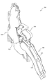
次いで、図34から図42を参照して、左揺動ユニット500について説明する。図34は、遊技盤13及び左揺動ユニット500の正面斜視図である。図34に示すように、左揺動ユニット500は、遊技盤13の第2可変入賞装置82a及び第2特定入賞口82の背面側に配設され、第2特定入賞口82に入賞した球を通過させる流路を内側に備える。本実施形態では、第2可変入賞装置82aと第2特定入賞口82との間に球が通過したことを検出するセンサ部材82bが配設される。なお、センサ部材82bは、各種スイッチ208(図4参照)の一部である。   Next, the left swing unit 500 will be described with reference to FIGS. 34 to 42. FIG. 34 is a front perspective view of the game board 13 and the left swing unit 500. As shown in FIG. 34, the left swing unit 500 is disposed on the back side of the second variable winning device 82a and the second specific winning port 82 of the game board 13, and the ball that won the second specific winning port 82 is displayed. A flow path is provided on the inside. In the present embodiment, a sensor member 82b that detects that a ball has passed is disposed between the second variable winning device 82a and the second specific winning port 82. The sensor member 82b is a part of various switches 208 (see FIG. 4).

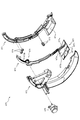
図35は、左揺動ユニット500の正面斜視図である。図35に示すように、左揺動ユニット500は、第1通路形成部材520を正面視右下方に垂らす態様で構成され、この第1通路形成部材520を揺動させることにより演出を行うユニットである。   FIG. 35 is a front perspective view of the left swing unit 500. As shown in FIG. 35, the left swing unit 500 is configured in such a manner that the first passage forming member 520 is hung downward and to the right when viewed from the front, and is a unit that produces effects by swinging the first passage forming member 520. is there.

図36は、左揺動ユニット500の分解正面斜視図であり、図37は、左揺動ユニット500の分解背面斜視図である。図36及び図37に図示されるように、左揺動ユニット500は、骨格を形成するベース部材510と、そのベース部材510に軸支され揺動動作される第1通路形成部材520と、ベース部材510に締結固定され第1通路形成部材520の駆動力を発生させる駆動装置530と、その駆動装置530の駆動力を第1通路形成部材520に伝達する伝達装置540と、正面側に覆設されベース部材510に締結固定されると共に遊技盤13の第2特定入賞口82に連結される導入円筒部552を有するカバー部材550と、を主に備える。   FIG. 36 is an exploded front perspective view of the left swing unit 500, and FIG. 37 is an exploded rear perspective view of the left swing unit 500. 36 and 37, the left swing unit 500 includes a base member 510 that forms a skeleton, a first passage forming member 520 that is pivotally supported by the base member 510, and a base. A driving device 530 that is fastened and fixed to the member 510 and generates a driving force of the first passage forming member 520; a transmission device 540 that transmits the driving force of the driving device 530 to the first passage forming member 520; And a cover member 550 having an introduction cylindrical portion 552 that is fastened and fixed to the base member 510 and connected to the second specific winning port 82 of the game board 13.

ベース部材510は、正面視L字の板状体から構成される本体部材511と、その本体部材の正面視右端部に前後方向に円形状で穿設される軸支孔512と、その軸支孔512の鉛直上方に配設され面を前後方向へ向ける平面板状に構成される第1壁部513と、その第1壁部513の左下端部から正面視左方に球一つ分以上の間隔を空けて配設され面を左右方向に向ける湾曲板状に構成される第2壁部514と、第2壁部514の背面側に配設され第2壁部514に到達した球が流下される流下通路515と、軸支孔512の正面視左下方に配設され正面側に円柱状に凸設される軸支部516と、その軸支部516の軸周りに配設される係止壁部517と、軸支部516の上方に配置され伝達装置の位相を検出する検出センサ518と、を主に備える。   The base member 510 includes a main body member 511 formed of a L-shaped plate body in front view, a shaft support hole 512 formed in a circular shape in the front-rear direction at the right end portion in front view of the main body member, and the shaft support. A first wall portion 513 that is disposed vertically above the hole 512 and has a planar plate shape with its surface facing in the front-rear direction, and one or more spheres leftward from the lower left end of the first wall portion 513 in front view. A second wall portion 514 configured in a curved plate shape that is disposed with a space therebetween and directs the surface in the left-right direction, and a sphere that is disposed on the back side of the second wall portion 514 and reaches the second wall portion 514 A downflow passage 515 that flows down, a shaft support portion 516 that is disposed in the lower left side of the shaft support hole 512 in front view and protrudes in a columnar shape on the front side, and a latch that is disposed around the shaft of the shaft support portion 516. A wall 517 and a detection sensor 518 disposed above the shaft support 516 to detect the phase of the transmission device; To prepare for.

軸支孔512は、第1通路形成部材520の軸支部521cが挿通される孔であり、第1通路形成部材520は軸支孔512を中心に揺動動作される。   The shaft support hole 512 is a hole through which the shaft support portion 521c of the first passage forming member 520 is inserted, and the first passage forming member 520 is swung around the shaft support hole 512.

第1壁部513は、左右方向両端部から正面側へ延設される一対の案内壁部513aを備える。   The 1st wall part 513 is provided with a pair of guide wall part 513a extended from the left-right direction both ends to the front side.

係止壁部517は、軸支部516の上方においてその軸支部516を中心とした円弧形状で構成される円弧壁部517aと、正面視右下方へ延設される傾斜壁部517bと、を備える。   The locking wall portion 517 includes an arc wall portion 517a having an arc shape centered on the shaft support portion 516 above the shaft support portion 516, and an inclined wall portion 517b extending to the lower right in front view. .

円弧壁部517aは、検出センサ518の端面であり軸支部516の周方向端面まで延設される。   The arc wall portion 517 a is an end surface of the detection sensor 518 and extends to a circumferential end surface of the shaft support portion 516.

第1通路形成部材520は、軸支孔512に軸支される部材である長尺棒状の振分ベース部材521と、その振分ベース部材521の正面側に配設され振分ベース部材521に締結固定されると共に振分ベース部材521との間に球が流下可能な通路を形成する通路カバー部材522と、を主に備える。   The first passage forming member 520 is a long rod-shaped distribution base member 521 that is a member supported by the shaft support hole 512, and is disposed on the front side of the distribution base member 521. And a passage cover member 522 that is fastened and fixed and forms a passage through which a sphere can flow down between the base member 521 and the sorting base member 521.

振分ベース部材521は、球の流下通路の一辺を構成する長尺板形状の垂下板部521aと、その垂下板部521aの上端部から垂下板部521aの延設方向に沿って球一つ分の隙間V1だけ離間した位置に配設される中間板部521bと、垂下板部521aの上端部付近において背面側に円柱状に凸設されると共に軸支孔512に挿通される軸支部521cと、その軸支部521cの径方向に延設される板状部にその延設方向に沿って穿設される長孔521dと、中間板部521bの垂下板部521a側の端部から背面側に凸設されると共に軸支部521cの径方向外側に向かうほど幅が短縮される態様で構成される振分凸部521eと、その振分凸部521eの背面視左側面に沿って隙間V1の正面側に延設され垂下板部521aの上端部に中心を有する円弧形状に沿って湾曲する湾曲壁部521fと、を主に備える。   The distribution base member 521 has a long plate-shaped hanging plate portion 521a that constitutes one side of the flow path of the sphere, and one sphere along the extending direction of the hanging plate portion 521a from the upper end portion of the hanging plate portion 521a. An intermediate plate portion 521b disposed at a position separated by a gap V1 and a shaft support portion 521c that protrudes in a columnar shape on the back side in the vicinity of the upper end portion of the hanging plate portion 521a and is inserted through the shaft support hole 512. A long hole 521d formed in a plate-like portion extending in the radial direction of the shaft support portion 521c along the extending direction, and a rear side from an end portion on the hanging plate portion 521a side of the intermediate plate portion 521b. And the gap V1 along the left side surface of the distribution convex portion 521e as viewed from the rear side, and a distribution convex portion 521e configured such that the width decreases toward the radially outer side of the shaft support portion 521c. The upper end of the hanging plate portion 521a that extends to the front side Mainly and a curved wall portion 521f which is curved along the arc shape having a center.

垂下板部521aは、中間部から下側が中間部から上側に比較して下方へ折れ曲げられる形状から構成され、その下端部に正面側の板厚部分が削られて薄板化される球送り部521a1を備える。   The drooping plate portion 521a has a shape in which the lower side from the middle portion is bent downward as compared with the upper side from the middle portion, and the front plate thickness portion is scraped and thinned at the lower end portion of the ball feeding portion. 521a1 is provided.

隙間V1は、振分凸部521eの正面視右側に到達した球を正面方向に通過させる空間である。   The gap V1 is a space through which a sphere that has reached the right side of the front surface of the distribution convex portion 521e passes in the front direction.

通路カバー部材522は、振分ベース部材521の正面側に覆設される板状の板状部522aと、その板状部522aの短手方向両端部から背面側に向けて板状に延設される上下壁部522bと、を主に備える。   The passage cover member 522 extends in the form of a plate from the plate-like plate-like portion 522a that covers the front side of the sorting base member 521, and from both ends in the short-side direction of the plate-like portion 522a toward the back side. The upper and lower wall portions 522b are mainly provided.

板状部522aは、光透過生の樹脂材料から形成され、その下端部の振分ベース部材521の球送り部521a1の正面側に配置される部分において背面側に屈曲される球受け部522a1を備える。   The plate-like portion 522a is formed of a light-transmitting resin material, and a ball receiving portion 522a1 bent at the back side in a portion disposed on the front side of the ball feeding portion 521a1 of the sorting base member 521 at the lower end thereof. Prepare.

上下壁部522bは、隙間V1を通過した球を転動させる部分であり、垂下板部521a同様に中間部を境に傾斜角度が変化するので、球の流下速度を中間部で変化させることができる。   The upper and lower wall portions 522b are portions for rolling the sphere that has passed through the gap V1, and the inclination angle changes at the intermediate portion as in the case of the hanging plate portion 521a. Therefore, the flow velocity of the sphere can be changed at the intermediate portion. it can.

上下壁部522bの内、下側の壁部には、先端部分の内側に段差が設けられる。その段差は、転動する球を上下壁部522bの対向方向(一方の壁部から他方の壁部へ向かう方向)に変位させ、球を減速させる役割を備える。   A step is provided on the lower wall portion of the upper and lower wall portions 522b inside the tip portion. The step has a role of decelerating the sphere by displacing the rolling sphere in a direction facing the upper and lower wall portions 522b (a direction from one wall portion to the other wall portion).

また、第1通路形成部材520の下端部まで到達した球は、球送り部521a1及び球受け部522a1により背面側に速度を向けられる。これにより、排出前の球の速度を減速させることができ、球の排出を安定させることができる。   Further, the sphere that has reached the lower end of the first passage forming member 520 is directed toward the back side by the ball feeding portion 521a1 and the ball receiving portion 522a1. Thereby, the speed of the sphere before discharge can be reduced, and the discharge of the sphere can be stabilized.

駆動装置530は、駆動モータ531と、その駆動モータ531の回転軸に軸支回転される駆動ギア532と、を備え、駆動ギア532が伝達装置540の本体ギア部541に歯合される。   The drive device 530 includes a drive motor 531 and a drive gear 532 that is pivotally supported on the rotation shaft of the drive motor 531, and the drive gear 532 is engaged with the main body gear portion 541 of the transmission device 540.

伝達装置540は、軸支部516に軸支され駆動ギア532に歯合される本体ギア部541と、その本体ギア部541の偏心した位置から正面側に円柱状に凸設され第1通路形成部材520の長孔521dに挿通される偏心凸部542と、本体ギア部541から径方向に延設され係止壁部517と当接可能に構成されると共に検出センサ518の隙間を通過可能とされる延設部543と、を主に備える。   The transmission device 540 includes a main body gear portion 541 that is pivotally supported by the shaft support portion 516 and meshed with the drive gear 532, and a first passage forming member that protrudes in a columnar shape from the eccentric position of the main body gear portion 541 to the front side. An eccentric convex portion 542 inserted into the long hole 521d of 520, a radial extension extending from the main body gear portion 541, and a contact with the locking wall portion 517 are possible, and the gap between the detection sensors 518 can be passed. Extending portion 543 mainly.

カバー部材550は、ベース部材510に覆設される板状の本体部材551と、その本体部材551の正面視右側端部において第2特定入賞口82に連結されると共に背面側端部が第1壁部513に当接される円筒形状の導入円筒部552と、本体部材551の背面側側面において導入円筒部552の左右方向端部から下方へ延設される一対の案内壁部553と、を主に備える。   The cover member 550 is connected to the plate-shaped main body member 551 that covers the base member 510, and the second specific prize opening 82 at the right end of the main body member 551 when viewed from the front, and the rear end is the first. A cylindrical introduction cylindrical portion 552 that comes into contact with the wall portion 513, and a pair of guide wall portions 553 that extend downward from the left and right end portions of the introduction cylindrical portion 552 on the back side surface of the main body member 551. Prepare mainly.

案内壁部553は、ベース部材510の案内壁部513aと前後方向で重なる部分である。導入円筒部552を通過した球は、案内壁部513a,553の間を通って下方へ流下される。   The guide wall portion 553 is a portion that overlaps with the guide wall portion 513a of the base member 510 in the front-rear direction. The sphere that has passed through the introduction cylindrical portion 552 flows down between the guide wall portions 513a and 553.

図38から図40を参照して、第1通路形成部材520の揺動動作について説明する。図38から図40は、揺動動作ユニット500の正面図である。なお、図38から図40では、カバー部材550の図示が省略されると共に第1通路形成部材520が垂下板部521aの前後方向中間位置で断面視された外形が図示されると共に通路カバー部材の外形形状が想像線で図示される。   With reference to FIGS. 38 to 40, the swinging operation of the first passage forming member 520 will be described. 38 to 40 are front views of the swing operation unit 500. FIG. 38 to 40, the illustration of the cover member 550 is omitted, the outer shape of the first passage forming member 520 viewed in cross-section at the middle position in the front-rear direction of the hanging plate portion 521a is shown, and the passage cover member The outer shape is illustrated with imaginary lines.

また、図38では、第1通路形成部材520が解除位置に配置された状態が、図39(a)では、第1通路形成部材520が図38に図示される状態から所定量揺動され振分凸部521eが一対の案内壁部513aの中間位置に配置された状態が、図39(b)では、第1通路形成部材520が図39(a)に図示される状態から所定量揺動され接続部材424に当接する直前の状態が、図40では、第1通路形成部材520が図39(b)に図示される状態から所定量揺動され連結位置に配置された状態がそれぞれ図示される。   38, the state where the first passage forming member 520 is disposed at the release position is shown in FIG. 39A. In FIG. 39A, the first passage forming member 520 is swung by a predetermined amount from the state shown in FIG. In the state where the minute convex portion 521e is disposed at the intermediate position between the pair of guide wall portions 513a, in FIG. 39 (b), the first passage forming member 520 swings a predetermined amount from the state shown in FIG. 39 (a). FIG. 40 shows a state immediately before contacting the connecting member 424, and FIG. 40 shows a state in which the first passage forming member 520 is swung by a predetermined amount from the state shown in FIG. The

図38から図40に示すように、第1通路形成部材520の揺動動作は、伝達装置540が回転され、偏心凸部542の移動に伴い長孔521dの位置が移動されることで生じる。   As shown in FIGS. 38 to 40, the swinging motion of the first passage forming member 520 occurs when the transmission device 540 is rotated and the position of the long hole 521d is moved along with the movement of the eccentric convex portion 542.

図38に示すように、解除位置では、軸支部516及び偏心凸部542を結ぶ方向X1と、長孔521dの延設方向(軸支部521cの径方向)と一致する方向X2とが垂直に交差する。そのため、第1通路形成部材520が回転動作しかけることにより偏心凸部542に与えられる負荷は軸支部516へ向けられるので、伝達装置540を回転させる負荷が生じることを抑制することができる。これにより、駆動ギア532に駆動力をかけ続けなくとも、伝達装置540の姿勢を維持する事ができ、駆動モータ531(図36参照)の消費電力を低減することができる。   As shown in FIG. 38, at the release position, the direction X1 connecting the shaft support portion 516 and the eccentric convex portion 542 and the direction X2 coinciding with the extending direction of the long hole 521d (the radial direction of the shaft support portion 521c) intersect perpendicularly. To do. Therefore, since the load given to the eccentric convex part 542 is directed to the shaft support part 516 when the first passage forming member 520 starts to rotate, it is possible to suppress the generation of a load that rotates the transmission device 540. Accordingly, the attitude of the transmission device 540 can be maintained without continuously applying a driving force to the drive gear 532, and the power consumption of the drive motor 531 (see FIG. 36) can be reduced.

また、解除位置において、伝達装置540の延設部543が、検出センサ518の隙間に配置されると共に円弧壁部517aの端部に当接される。即ち、延設部543は、伝達装置540の位相の検出に利用される部分としての役割と、回り止め部材としての役割とを共に有する。   Further, at the release position, the extending portion 543 of the transmission device 540 is disposed in the gap of the detection sensor 518 and is in contact with the end portion of the arc wall portion 517a. That is, the extending portion 543 has both a role as a portion used for detecting the phase of the transmission device 540 and a role as a rotation preventing member.

図38に示すように、解除位置において、振分凸部521eがベース部材510の正面視右側の案内壁部513aと対向配置される。そのため、第1壁部513に到達し案内壁部513a,553の間を通過した球は、振分凸部521eにより正面視左側の経路に振り分けられ、流下通路515を通って遊技領域外に排出される。   As shown in FIG. 38, at the release position, the distribution convex portion 521e is disposed to face the guide wall portion 513a on the right side of the base member 510 when viewed from the front. Therefore, the sphere that has reached the first wall portion 513 and passed between the guide wall portions 513a and 553 is distributed to the path on the left side of the front view by the distribution convex portion 521e, and is discharged out of the game area through the flow-down passage 515. Is done.

図39(a)に示すように、解除位置と連結位置との間の中間位置において、振分凸部521eがベース部材510の一対の案内壁部513aの中間位置に配置される。そのため、第1壁部513に到達し案内壁部513a,553の間を通過した球は、振分凸部521eにより流下を停止される(振分凸部521eの先端部に乗ったまま、留まる)。   As shown in FIG. 39A, the distribution convex portion 521e is disposed at an intermediate position between the pair of guide wall portions 513a of the base member 510 at an intermediate position between the release position and the connection position. Therefore, the sphere that has reached the first wall portion 513 and passed between the guide wall portions 513a and 553 is stopped by the distribution convex portion 521e (it remains on the tip of the distribution convex portion 521e). ).

図39(b)に示すように、第1通路形成部材520が接続部材424に当接する直前の状態において、振分凸部521eがベース部材510の一対の案内壁部513aの間に配置される、そのため、第1壁部513に到達し案内壁部513a,553の間を通過した球は、振分凸部521eにより流下を停止される(振分凸部521eの先端部に乗ったまま、留まる)。これにより、図39(b)の状態において球が第1通路形成部材520を通過し、接続部材424に送球され、対向壁部422f2に球が到達することが防止される。   As shown in FIG. 39B, the distribution convex portion 521 e is disposed between the pair of guide wall portions 513 a of the base member 510 in a state immediately before the first passage forming member 520 contacts the connection member 424. Therefore, the sphere that has reached the first wall portion 513 and has passed between the guide wall portions 513a and 553 is stopped by the distribution convex portion 521e (while remaining on the tip of the distribution convex portion 521e, stay). Thereby, in the state of FIG. 39B, the sphere passes through the first passage forming member 520, is sent to the connecting member 424, and the sphere is prevented from reaching the opposing wall portion 422f2.

ここで、対向壁部422f2は、上傾斜状態(図42参照)において接続部材424の上側壁部424bと滑らかに連結されるので、下傾斜状態(図41参照)では、上端部が接続部材424の上側壁部424bの下端部から正面視左方に張り出す態様とされる。そのため、下傾斜状態で接続部材424に球が送球され、対向壁部422f2の上端部に球が衝突すると、対向壁部422f2が破損する恐れがある。   Here, since the opposing wall portion 422f2 is smoothly connected to the upper wall portion 424b of the connection member 424 in the upward inclined state (see FIG. 42), the upper end portion is connected to the connecting member 424 in the downward inclined state (see FIG. 41). It is set as the aspect which protrudes from the lower end part of the upper side wall part 424b to front view left side. Therefore, when the sphere is sent to the connection member 424 in the downward inclined state and the sphere collides with the upper end portion of the opposing wall portion 422f2, the opposing wall portion 422f2 may be damaged.

これに対し、本実施形態では、図39(b)に示す状態において、第1通路形成部材520への球の導入が防止されるので、対向壁部422f2に球が衝突することを防止でき、対向壁部422f2が破損することを防止することができる。   On the other hand, in the present embodiment, in the state shown in FIG. 39 (b), since the introduction of the sphere into the first passage forming member 520 is prevented, it is possible to prevent the sphere from colliding with the opposing wall portion 422f2. It is possible to prevent the opposing wall portion 422f2 from being damaged.

図40に示すように、連結位置では、軸支部516及び偏心凸部542を結ぶ方向X1と、長孔521dの延設方向(軸支部521cの径方向)と一致する方向X2とが垂直に交差する。そのため、第1通路形成部材520が回転動作しかけることにより偏心凸部542に与えられる負荷は軸支部516へ向けられるので、伝達装置540を回転させる負荷が生じることを抑制することができる。これにより、駆動ギア532に駆動力をかけ続けなくとも、伝達装置540の姿勢を維持する事ができ、駆動モータ531(図36参照)の消費電力を低減することができる。   As shown in FIG. 40, at the connecting position, the direction X1 connecting the shaft support portion 516 and the eccentric convex portion 542 and the direction X2 coinciding with the extending direction of the long hole 521d (the radial direction of the shaft support portion 521c) intersect perpendicularly. To do. Therefore, since the load given to the eccentric convex part 542 is directed to the shaft support part 516 when the first passage forming member 520 starts to rotate, it is possible to suppress the generation of a load that rotates the transmission device 540. Accordingly, the attitude of the transmission device 540 can be maintained without continuously applying a driving force to the drive gear 532, and the power consumption of the drive motor 531 (see FIG. 36) can be reduced.

また、連結位置において、伝達装置540の延設部543が、傾斜壁部517bに面当たりされる。これにより、延設部543を傾斜壁部517bに突き当てることで伝達装置540を停止させる位相を安定させながら、延設部543に局部的に荷重が負荷される場合に比較して延設部543の耐久性を向上させることができる。   In addition, the extended portion 543 of the transmission device 540 comes into contact with the inclined wall portion 517b at the coupling position. Thus, the extension portion 543 is compared with a case where a load is locally applied to the extension portion 543 while stabilizing the phase of stopping the transmission device 540 by abutting the extension portion 543 against the inclined wall portion 517b. The durability of 543 can be improved.

図40に示すように、連結状態において、振分凸部521eがベース部材510の正面視左側の案内壁部513aと対向配置される。そのため、第1壁部513に到達し案内壁部513a,553の間を通過した球は、振分凸部521eにより正面視右側の経路に振り分けられ、隙間V1を通って正面側に移動してから通路カバー部材522の上下壁部522b(図37参照)の下側の壁部に沿って転動する。   As shown in FIG. 40, in the connected state, the distribution convex portion 521e is disposed to face the guide wall portion 513a on the left side of the base member 510 when viewed from the front. Therefore, the sphere that reaches the first wall portion 513 and passes between the guide wall portions 513a and 553 is distributed to the path on the right side of the front view by the distribution convex portion 521e, and moves to the front side through the gap V1. Rolling along the lower wall portion of the upper and lower wall portions 522b (see FIG. 37) of the passage cover member 522.

連結状態での球の流れについて説明する。まず、遊技領域から第2可変入賞装置82aを通って第2特定入賞口82に入賞した球は導入円筒部552(図36参照)を通って背面側へ向けて前後移動し、第1壁部513に当接されると案内壁部513a,553の形成する通路を流下し、第1通路形成部材520の隙間V1を通って正面側へ向けて前後移動し、通路カバー部材522の上下壁部522bの下側の壁部の上を転動する。   The flow of the sphere in the connected state will be described. First, the ball that has won the second specific prize opening 82 from the game area through the second variable prize-winning device 82a moves back and forth through the introduction cylindrical part 552 (see FIG. 36) toward the back side, and the first wall part When contacted with 513, it flows down the passage formed by the guide wall portions 513a and 553, moves back and forth toward the front side through the gap V1 of the first passage forming member 520, and the upper and lower wall portions of the passage cover member 522 Roll over the lower wall of 522b.

即ち、球が第1通路形成部材520の内部を流下する前に、球が前後方向に送られる。そのため、第2特定入賞口82に球が数珠つなぎで供給されても、球の跳ね等を抑制して、第1通路形成部材520にスムーズに球を流入させることができる。また、前後方向に送られた球を湾曲壁部521f(図37参照)に沿って流下させることにより、球の速度の向きを変えることができ、第1通路形成部材520に球をスムーズに流入させることができる。   That is, before the sphere flows down inside the first passage forming member 520, the sphere is sent in the front-rear direction. Therefore, even if the balls are supplied to the second specific winning opening 82 by connecting them in a rosary manner, the balls can be smoothly flowed into the first passage forming member 520 by preventing the balls from jumping. Further, the direction of the speed of the sphere can be changed by flowing down the sphere sent in the front-rear direction along the curved wall portion 521f (see FIG. 37), and the sphere smoothly flows into the first passage forming member 520. Can be made.

第1通路形成部材520は、振分ベース部材521及び通路カバー部材522が、中間部を境に延設方向が変化する。即ち、振分ベース部材521及び通路カバー部材522が、中間部から基端側(軸支部521c側)までは直線Y1に沿って延設され、中間部から先端側(基端側の逆側)までは直線Y1よりも下方へ傾斜される直線Y2に沿って延設される。   As for the 1st channel | path formation member 520, the extending direction changes the boundary base member 521 and the channel | path cover member 522 on the boundary of an intermediate part. That is, the distribution base member 521 and the passage cover member 522 extend along the straight line Y1 from the intermediate portion to the proximal end side (the shaft support portion 521c side), and from the intermediate portion to the distal end side (the opposite side of the proximal end side). Is extended along a straight line Y2 inclined downward from the straight line Y1.

そのため、第1通路形成部材520の内部を転動する球の速度が、基端側から中間部へ到達するまでの間の方が、中間部から先端部へ向かうまでの間に比較して遅くなる。そのため、第1通路形成部材520へ球が導入した直後に遊技者に球を視認させやすくすることができる。   Therefore, the speed of the sphere rolling inside the first passage forming member 520 is slower when it reaches the intermediate portion from the base end side than when it moves from the intermediate portion toward the distal end portion. Become. Therefore, it is possible to make it easier for the player to visually recognize the ball immediately after the ball is introduced into the first passage forming member 520.

また、直線Y1に沿った真っ直ぐな形状で第1通路形成部材520が構成される場合に比較して、連結位置(図42参照)において、第1通路形成部材520から球が送球される方向と、センサ部材422cに球が導入される方向(鉛直方向)との角度を小さくすることができる。これにより、第1通路形成部材520から第2通路形成部材422への球の送球を安定させることができる。   Further, as compared with the case where the first passage forming member 520 is configured in a straight shape along the straight line Y1, the direction in which the ball is sent from the first passage forming member 520 at the connection position (see FIG. 42) The angle with the direction (vertical direction) in which the sphere is introduced into the sensor member 422c can be reduced. Thereby, ball feeding from the first passage forming member 520 to the second passage forming member 422 can be stabilized.

図38から図40に図示されるように、伝達装置540の回転により第1通路形成部材520が揺動され、振分凸部521eの配置によって球が流下される経路が切り替えられる。   As shown in FIGS. 38 to 40, the first passage forming member 520 is swung by the rotation of the transmission device 540, and the path through which the sphere flows down is switched by the arrangement of the distribution convex portions 521e.

ここで、振分凸部521eの回転方向において振分凸部521eと対向配置される壁部材が配置される場合に、その壁部材に対して振分凸部521eが球の直径以下にまで近づける構成を採用すると、球が振分凸部521eの回転方向に滞留した場合に振分凸部521eと壁部材との間に球が噛み込まれ、動作不良を起こす恐れがある。   Here, when a wall member disposed opposite to the distribution convex portion 521e in the rotation direction of the distribution convex portion 521e is disposed, the distribution convex portion 521e approaches the wall member to be equal to or less than the diameter of the sphere. When the configuration is adopted, when the sphere stays in the rotation direction of the distribution convex portion 521e, the sphere is caught between the distribution convex portion 521e and the wall member, which may cause malfunction.

これに対し、本実施形態では、図40に図示される連結位置において、振分凸部521eと第2壁部514との間には、球の直径以上の間隔が空けられ、振分凸部521eを挟んで第2壁部514の反対側には壁部材は配置されず開放される。従って、振分凸部521eの回転方向で球を噛み込むという事態を生じることが無く、動作不良を防止することができる。   On the other hand, in the present embodiment, at the connection position illustrated in FIG. 40, an interval equal to or larger than the diameter of the sphere is provided between the distribution convex portion 521e and the second wall portion 514, and the distribution convex portion. A wall member is not disposed on the opposite side of the second wall portion 514 across the 521e and is opened. Therefore, a situation in which the ball is bitten in the rotation direction of the distribution convex portion 521e does not occur, and malfunction can be prevented.

図41及び図42を参照して、液晶昇降ユニット400と左揺動ユニット500との流路の接続について説明する。図41及び図42は、液晶昇降ユニット400及び左揺動ユニット500の部分正面図である。なお、図41及び図42では、第2通路形成部材422が断面視され接続部材424が視認可能とされると共に、第1通路形成部材520が垂下板部521aの前後方向中間位置における外形形状で図示され振分凸部521eが視認可能とされる。   With reference to FIG.41 and FIG.42, the connection of the flow path of the liquid crystal raising / lowering unit 400 and the left swing unit 500 is demonstrated. 41 and 42 are partial front views of the liquid crystal lifting unit 400 and the left swing unit 500. FIG. 41 and 42, the second passage forming member 422 is viewed in cross section so that the connection member 424 is visible, and the first passage forming member 520 has an outer shape at an intermediate position in the front-rear direction of the hanging plate portion 521a. The distribution convex part 521e shown in figure is visible.

また、図41及び図42では、液晶昇降ユニット400が連結位置(図31参照)に配置された状態が図示され、図41では、左揺動ユニット500が解除位置(図38参照)に配置された状態が図示され、図42では、左揺動ユニット500が連結位置(図40参照)に配置された状態が図示される。   41 and 42 show a state in which the liquid crystal lifting / lowering unit 400 is disposed at the connection position (see FIG. 31), and in FIG. 41, the left swing unit 500 is disposed at the release position (see FIG. 38). FIG. 42 shows a state in which the left swing unit 500 is disposed at the coupling position (see FIG. 40).

図41に示す状態から図42に示す状態に第1通路形成部材520が揺動動作されると、その先端部が接続部材424の上側壁部424bの下側側面に当接し、接続部材424を揺動させる。即ち、接続部材424が第1通路形成部材520の移動方向に連れ立って移動されるので、例えば、駆動側スライド部材420の停止位置が理想的な位置から若干ずれた場合であっても、第1通路形成部材520の先端と接続部材424との間に隙間が生じることを抑制することができる。これにより、球が第1通路形成部材520の先端と接続部材424との間に落下することを抑制し、第1通路形成部材520から第2通路形成部材422への球の送球を安定させることができる。   When the first passage forming member 520 is swung from the state shown in FIG. 41 to the state shown in FIG. 42, the distal end of the first passage forming member 520 comes into contact with the lower side surface of the upper wall portion 424b of the connecting member 424, Rock. That is, since the connecting member 424 is moved along with the moving direction of the first passage forming member 520, for example, even if the stop position of the driving side slide member 420 is slightly deviated from the ideal position, It is possible to suppress the generation of a gap between the tip of the passage forming member 520 and the connection member 424. Thereby, it is possible to suppress the sphere from falling between the tip of the first passage forming member 520 and the connection member 424, and to stabilize the ball feeding from the first passage forming member 520 to the second passage forming member 422. Can do.

接続部材424が揺動されることにより、第1通路形成部材520から流下された球が転動する下側壁部424cが第1通路形成部材520の先端へ近接する方向へ移動されるので、第1通路形成部材520と接続部材424との転動面間の隙間を狭めることができ、球が第1通路形成部材520と接続部材424との転動面間の隙間から落下することを抑制することができるので、球の送球を安定させることができる。   As the connecting member 424 is swung, the lower wall portion 424c on which the sphere flowing down from the first passage forming member 520 rolls is moved in a direction approaching the tip of the first passage forming member 520. The gap between the rolling surfaces of the first passage forming member 520 and the connecting member 424 can be narrowed, and the sphere is prevented from falling from the gap between the rolling surfaces of the first passage forming member 520 and the connecting member 424. This makes it possible to stabilize ball feeding.

また、図42に示す状態において、下側壁部424cが溝部422d(図27参照)に連通されるセンサ部材422cへ向けて下降傾斜される。これにより、球をその下降傾斜に沿って転動させることができ、第2通路形成部材422への球の送球を安定させることができる。   Further, in the state shown in FIG. 42, the lower side wall 424c is inclined downward toward the sensor member 422c communicated with the groove 422d (see FIG. 27). Thereby, the sphere can be rolled along its descending slope, and the sphere can be sent to the second passage forming member 422 in a stable manner.

なお、第1通路形成部材520の揺動動作は、センサ部材82b(図34参照)やセンサ部材422cの球の通過を検出して、行われる。例えば、図42に示す連結位置に第1通路形成部材520が配置された状態において、センサ部材82bとセンサ部材422cとの球の検出個数が合致する(第1通路形成部材520に球が残留していない)タイミングで第1通路形成部材520を解除位置(図41参照)へ向けて揺動開始させることで、第1通路形成部材520の先端から遊技領域外に球が排出されることを防止することができる。   The swinging motion of the first passage forming member 520 is performed by detecting the passage of the sphere of the sensor member 82b (see FIG. 34) or the sensor member 422c. For example, in the state where the first passage forming member 520 is disposed at the coupling position shown in FIG. 42, the number of detected balls of the sensor member 82b and the sensor member 422c matches (the sphere remains on the first passage forming member 520). The first passage forming member 520 starts swinging toward the release position (see FIG. 41) at the timing, thereby preventing the ball from being discharged out of the game area from the tip of the first passage forming member 520. can do.

図41及び図42に図示されるように、振分凸部521eの移動による球の振り分けと、第1通路形成部材520を揺動させることにより第1通路形成部材520と接続部材424とを当接させて球の流下経路を形成する動作とに必要な駆動力が兼用される(第1通路形成部材520を動作させる駆動モータ531(図36参照)の駆動力でまかなわれる)また、両者の状態が同期されるので、例えば、第1通路形成部材520が解除位置に配置される状態において球が第1通路形成部材520に導入される事態を回避することができる。その結果、第1通路形成部材520の先端から球が遊技領域外に排出されることを確実に防止することができる。   As shown in FIGS. 41 and 42, balls are distributed by the movement of the distribution convex portion 521e, and the first passage forming member 520 is swung so that the first passage forming member 520 and the connection member 424 are brought into contact with each other. The driving force necessary for the contact and the operation of forming the flow path of the sphere is also used (covered by the driving force of the drive motor 531 (see FIG. 36) that operates the first passage forming member 520). Since the states are synchronized, for example, it is possible to avoid a situation where a sphere is introduced into the first passage forming member 520 in a state where the first passage forming member 520 is disposed at the release position. As a result, it is possible to reliably prevent the ball from being discharged out of the game area from the tip of the first passage forming member 520.

また、振分凸部521eは振分ベース部材521の上端部に配設され、垂下板部521a(図36参照)の正面側を流下する球の通路を区画する(上端を形成する)壁部を兼ねる。これにより、他の部品で振分を行う場合に比較して部品コストの削減を図ることができると共に、第1通路形成部材520側に振り分けられた球を確実に垂下板部521aと通路カバー部材522との間の通路に導入させることができる。   The distribution convex portion 521e is disposed on the upper end portion of the distribution base member 521, and defines a wall path of a sphere that flows down the front side of the hanging plate portion 521a (see FIG. 36) (forms an upper end). Doubles as As a result, it is possible to reduce the cost of parts compared to the case where the other parts are distributed, and to ensure that the balls distributed to the first passage forming member 520 side are suspended from the hanging plate portion 521a and the passage cover member. 522 can be introduced into the passage between the two.

次いで、図43から図77を参照して、回転ユニット600について説明する。図43は、回転ユニット600の正面図であり、図44は、回転ユニット600の正面斜視図である。図45は、ガイド部材680が取り外された状態における回転ユニット600の正面図であり、図46は、ガイド部材680が取り外された状態における回転ユニット600の正面斜視図である。また、図47は、回転ユニット600の分解正面斜視図であり、図48は、回転ユニット600の分解背面斜視図である。   Next, the rotation unit 600 will be described with reference to FIGS. 43 to 77. 43 is a front view of the rotation unit 600, and FIG. 44 is a front perspective view of the rotation unit 600. 45 is a front view of the rotating unit 600 with the guide member 680 removed, and FIG. 46 is a front perspective view of the rotating unit 600 with the guide member 680 removed. 47 is an exploded front perspective view of the rotating unit 600, and FIG. 48 is an exploded rear perspective view of the rotating unit 600.

図43から図48に示すように、回転ユニット600は、一面側が開放された容器状に形成されるケース部材610と、そのケース部材610の一面側に覆設される案内部材620と、それらケース部材610及び案内部材620の対向間に配設される駆動機構630と、その駆動機構630の駆動力により回転駆動される回転部材640と、その回転部材640の内周側に配設される投球装置650と、回転部材640の外周側に配設されるガイド部材680と、を主に備える。   As shown in FIGS. 43 to 48, the rotation unit 600 includes a case member 610 formed in a container shape with one side opened, a guide member 620 covered on one side of the case member 610, and the cases. A driving mechanism 630 disposed between the member 610 and the guide member 620 facing each other, a rotating member 640 rotated by the driving force of the driving mechanism 630, and a pitching disposed on the inner peripheral side of the rotating member 640 The apparatus 650 mainly includes a guide member 680 disposed on the outer peripheral side of the rotating member 640.

ケース部材610は、正面視略円形の底壁部611と、その底壁部611から正面へ向けて立設される略円筒状の外壁部612とを備え、これら各壁部611,612により一面側が開放された容器状に形成される。案内部材620は、正面視円環の円板状に形成され、ケース部材610の外壁部612の立設先端に配設(固着)される。これにより、ケース部材610の底壁部611と案内部材620との間に内部空間が形成され、その内部空間に駆動機構630が配設される。   The case member 610 includes a bottom wall portion 611 having a substantially circular shape when viewed from the front, and a substantially cylindrical outer wall portion 612 erected from the bottom wall portion 611 toward the front surface. It is formed in a container shape whose side is open. The guide member 620 is formed in a disc shape with an annular shape when viewed from the front, and is disposed (adhered) to the standing tip of the outer wall portion 612 of the case member 610. Thus, an internal space is formed between the bottom wall portion 611 of the case member 610 and the guide member 620, and the drive mechanism 630 is disposed in the internal space.

案内部材620は、回転部材640を変位可能に保持するための部材であり、その正面に連結リンク作用溝621及び起伏リンク作用溝622が凹設される。これら連結リンク作用溝621及び起伏リンク作用溝622は、案内部材620の周方向に沿って延設される断面コ字状の凹溝であり、回転部材640の後述する連結リンク部材644及び起伏リンク部材648の挿通部644a,648aがそれぞれ挿通される。   The guide member 620 is a member for holding the rotating member 640 so as to be displaceable, and a connection link action groove 621 and an undulating link action groove 622 are recessed in the front surface thereof. The connection link action groove 621 and the undulation link action groove 622 are concave grooves having a U-shaped cross section extending along the circumferential direction of the guide member 620, and the connection link member 644 and the undulation link, which will be described later, of the rotation member 640. The insertion portions 644a and 648a of the member 648 are respectively inserted.

なお、連結リンク作用溝621及び起伏リンク作用溝622の溝幅は、連結リンク部材644及び起伏リンク部材648の挿通部644a,648aの直径と同等または若干大きな寸法に設定される。よって、連結リンク部材644及び起伏リンク部材648の挿通部644a,648aは、連結リンク作用溝621及び起伏リンク作用溝622の延設方向に沿って摺動(案内)可能とされる。   In addition, the groove widths of the connection link action groove 621 and the undulation link action groove 622 are set to dimensions that are equal to or slightly larger than the diameters of the insertion portions 644 a and 648 a of the connection link member 644 and the undulation link member 648. Therefore, the insertion portions 644a and 648a of the connecting link member 644 and the undulating link member 648 can slide (guide) along the extending direction of the connecting link operating groove 621 and the undulating link operating groove 622.

回転部材640が回転駆動される際に、連結リンク作用溝621は、連結リンク部材644に作用して、分割部材DVどうしの間隔を増減させる一方(図73参照)、起伏リンク作用溝622は、起伏リンク部材648に作用して、表示板646及び区画板647を起伏させる(図59及び図60参照)。ここで、図49及び図50を参照して、案内部材620の連結リンク作用溝621及び起伏リンク作用溝622について説明する。   When the rotation member 640 is driven to rotate, the connection link operation groove 621 acts on the connection link member 644 to increase or decrease the interval between the divided members DV (see FIG. 73), while the undulation link operation groove 622 It acts on the undulating link member 648 to undulate the display plate 646 and the partition plate 647 (see FIGS. 59 and 60). Here, with reference to FIG. 49 and FIG. 50, the connecting link working groove 621 and the undulating link working groove 622 of the guide member 620 will be described.

図49は、回転部材640、投球装置650の一部およびガイド部材680が取り外された状態における回転ユニット600の正面図であり、図50は、案内部材620の正面模式図である。なお、図50では、連結リンク作用溝621及び起伏リンク作用溝622の形状が二点鎖線を用いて模式的に図示される。かかる二点鎖線は、各作用溝621,622の溝幅の中央を通る線として図示される。   49 is a front view of the rotation unit 600 in a state where the rotation member 640, a part of the pitching device 650, and the guide member 680 are removed, and FIG. 50 is a schematic front view of the guide member 620. In FIG. 50, the shapes of the connecting link working groove 621 and the undulating link working groove 622 are schematically illustrated using a two-dot chain line. Such a two-dot chain line is illustrated as a line passing through the center of the groove width of each working groove 621, 622.

図49及び図50に示すように、連結リンク作用溝621は、軸心Oを中心として半径R1で円弧状に湾曲する大径部621aと、軸心Oを中心として半径R2で円弧状に湾曲する小径部621bと、それら大径部621a及び小径部621bの間を接続する一対の接続部621cとからなる。なお、大径部621aの半径R1は、小径部621bの半径R2よりも大きな寸法に設定される(R2<R1)。   As shown in FIGS. 49 and 50, the connecting link working groove 621 has a large-diameter portion 621a that curves in an arc shape with a radius R1 around the axis O, and an arc shape with a radius R2 around the axis O. And a pair of connecting portions 621c that connect the large diameter portion 621a and the small diameter portion 621b. The radius R1 of the large diameter portion 621a is set to be larger than the radius R2 of the small diameter portion 621b (R2 <R1).

起伏リンク作用溝622は、軸心Oを中心として半径R3で円弧状に湾曲する大径部622aと、軸心Oを中心として半径R4で円弧状に湾曲する小径部622bと、それら大径部622a及び小径部622bの間を接続する一対の接続部622cとからなる。なお、大径部622aの半径R3は、小径部622bの半径R4よりも大きな寸法に設定される(R4<R3)。   The undulating link working groove 622 includes a large-diameter portion 622a that is curved in an arc shape with a radius R3 around the axis O, a small-diameter portion 622b that is curved in an arc shape with a radius R4 around the axis O, and these large-diameter portions. It consists of a pair of connection part 622c which connects between 622a and the small diameter part 622b. The radius R3 of the large diameter portion 622a is set to be larger than the radius R4 of the small diameter portion 622b (R4 <R3).

本実施形態では、連結リンク作用溝621の大径部621a及び小径部621bと、起伏リンク作用溝622の大径部622a及び小径部622bとが、軸心Oを中心として同心に配置される。この場合、軸心Oは、回転部材640が回転される際の回転中心に一致される。よって、回転部材640が回転される際に、連結リンク作用溝621及び起伏リンク作用溝622の大径部621a,622a及び小径部622a,622bから連結リンク部材644及び起伏リンク部材648へそれぞれ作用する力を抑制して、駆動機構630の駆動モータ631に必要とされる出力を小さくできる。   In the present embodiment, the large-diameter portion 621a and the small-diameter portion 621b of the connecting link working groove 621 and the large-diameter portion 622a and the small-diameter portion 622b of the undulating link working groove 622 are arranged concentrically about the axis O. In this case, the axis O coincides with the rotation center when the rotating member 640 is rotated. Therefore, when the rotating member 640 is rotated, the large diameter portions 621a and 622a and the small diameter portions 622a and 622b of the connecting link working groove 621 and the undulating link working groove 622 act on the connecting link member 644 and the undulating link member 648, respectively. By suppressing the force, the output required for the drive motor 631 of the drive mechanism 630 can be reduced.

また、連結リンク作用溝621の一対の接続部621cは、180度位相を異ならせた位置に配置される。同様に、起伏リンク作用溝622の一対の接続部622cは、180度位相を異ならせた位置に配置される。よって、回転部材640が回転駆動される際に、連結リンク作用溝621の一方の接続部621cから連結リンク部材644へ作用される力と他方の接続部621cから連結リンク部材644へ作用される力とを相殺させることができる。同様に、起伏リンク作用溝622の一方の接続部622cから起伏リンク部材648へ作用される力と他方の接続部622cから起伏リンク部材648へ作用される力とを相殺させることができる。これにより、回転部材640に作用される力を全体として均一化できるので、その回転部材640の回転を安定化させることができると共に、駆動機構630の駆動モータ631に必要とされる出力を小さくできる。   Further, the pair of connection portions 621c of the connection link action groove 621 are arranged at positions that are different in phase by 180 degrees. Similarly, the pair of connecting portions 622c of the undulating link action groove 622 are arranged at positions that are different in phase by 180 degrees. Therefore, when the rotating member 640 is rotationally driven, a force that is applied to the connecting link member 644 from one connecting portion 621c of the connecting link operating groove 621 and a force that is applied to the connecting link member 644 from the other connecting portion 621c. Can be offset. Similarly, the force applied to the undulation link member 648 from one connection portion 622c of the undulation link operation groove 622 can be canceled out from the force applied to the undulation link member 648 from the other connection portion 622c. Thereby, since the force applied to the rotating member 640 can be made uniform as a whole, the rotation of the rotating member 640 can be stabilized and the output required for the drive motor 631 of the drive mechanism 630 can be reduced. .

なお、本実施形態では、連結リンク作用溝621の接続部621cと起伏リンク作用溝622の接続部622cとが異なる位相となるように形成される。即ち、連結リンク作用溝621の接続部621cに連結リンク部材644の挿通部644aが挿通されている状態では、起伏リンク部材648の挿通部648aは、起伏リンク作用溝622の大径部622a又は小径部622bのいずれか一方に挿通されると共に、起伏リンク作用溝622の接続部622cに起伏リンク部材648の挿通部648aが挿通されている状態では、連結リンク部材644の挿通部644aは、連結リンク作用溝621の大径部621a又は小径部621bのいずれか一方に挿通される。   In this embodiment, the connecting portion 621c of the connecting link working groove 621 and the connecting portion 622c of the undulating link working groove 622 are formed to have different phases. That is, in a state where the insertion portion 644a of the connection link member 644 is inserted into the connection portion 621c of the connection link operation groove 621, the insertion portion 648a of the undulation link member 648 is the large diameter portion 622a or the small diameter portion of the undulation link operation groove 622. When the insertion portion 648a of the undulation link member 648 is inserted into the connection portion 622c of the undulation link action groove 622, the insertion portion 644a of the connection link member 644 is inserted into one of the portions 622b. The working groove 621 is inserted into either the large diameter part 621a or the small diameter part 621b.

接続部621c,622cは分割部材DVの間隔を変更する又は表示板646及び区画板647を変位させるための部位であるため、かかる接続部621c,622cから比較的大きな反力を受けるところ、挿通部644a,648aが接続部621c,622cに同時に挿通されないようにすることで、必要な駆動力を分散させることができる。その結果、駆動機構630の駆動モータ631に必要とされる出力を小さくできる。   Since the connection portions 621c and 622c are portions for changing the interval of the divided member DV or displacing the display plate 646 and the partition plate 647, the insertion portion receives a relatively large reaction force from the connection portions 621c and 622c. By preventing the 644a and 648a from being inserted through the connecting portions 621c and 622c at the same time, the necessary driving force can be dispersed. As a result, the output required for the drive motor 631 of the drive mechanism 630 can be reduced.

図43から図48に戻って、駆動機構630について説明する。駆動機構630は、回転部材640を回転駆動するための機構であり、駆動モータ631と、その駆動モータ631の駆動軸に固着されるピニオンギヤ632と、そのピニオンギヤ632に先頭のギヤ(第1伝達ギヤ633a)が歯合される伝達ギヤ列と、その伝達ギヤ列の末尾のギヤ(第2伝達ギヤ633b)に歯合されるギヤ634aを有する中央伝達体634と、その中央伝達部材634のギヤ634aに先頭のギヤ(第1分配ギヤ635a,636a)が歯合される一側分配ギヤ列および他側分配ギヤ列と、それら一側分配ギヤ列および他側ギヤ列の末尾のギヤ(第3分配ギヤ635c,636c)に歯合されるギヤ637a,638aを有する一側回転駆動部材637及び他側回転駆動部材638と、を主に備える。なお、第1分配ギヤ635a,636aと第3分配ギヤ635c,636cの間には第2分配ギヤ635b,636bがそれぞれ介在される。   Returning from FIG. 43 to FIG. 48, the drive mechanism 630 will be described. The drive mechanism 630 is a mechanism for rotationally driving the rotation member 640, and includes a drive motor 631, a pinion gear 632 fixed to the drive shaft of the drive motor 631, and a leading gear (first transmission gear) to the pinion gear 632. 633a), a central transmission body 634 having a gear 634a meshed with the last gear (second transmission gear 633b) of the transmission gear train, and a gear 634a of the central transmission member 634 One side distribution gear train and the other side distribution gear train meshed with the leading gear (first distribution gears 635a, 636a) and the last gear (third distribution gear train) of the one side distribution gear train and the other side gear train 1 side rotation drive member 637 and other side rotation drive member 638 which have gears 637a and 638a meshed with gears 635c and 636c) are mainly provided. Note that second distribution gears 635b and 636b are interposed between the first distribution gears 635a and 636a and the third distribution gears 635c and 636c, respectively.

一側回転駆動部材637及び他側回転駆動部材638は、駆動モータ631から発生された回転駆動力を伝達する伝達経路の末尾(駆動機構630における出力端)となる部材であり、駆動モータ631の回転駆動力により自身が回転されると共に、その回転により回転部材640を回転させる。ここで、一側回転駆動部材637及び他側回転駆動部材638について、図51を参照して説明する。   The one side rotation drive member 637 and the other side rotation drive member 638 are members that become the end of the transmission path (the output end in the drive mechanism 630) that transmits the rotation drive force generated from the drive motor 631. While rotating itself by the rotational driving force, the rotating member 640 is rotated by the rotation. Here, the one side rotation driving member 637 and the other side rotation driving member 638 will be described with reference to FIG.

図51(a)は、一側回転駆動部材637及び他側回転部材638の正面図であり、図51(b)は、図51(a)のLIb−LIb線における一側回転部材637及び他側回転部材638の断面図である。   FIG. 51A is a front view of the one-side rotation driving member 637 and the other-side rotation member 638, and FIG. 51B is a one-side rotation member 637 and the others on the LIb-LIb line in FIG. 6 is a cross-sectional view of a side rotation member 638. FIG.

なお、一側回転駆動部材637及び他側回転駆動部材638は、互いに同一の形状に形成される部材であるので、一側回転駆動部材637のみについて説明し、他側回転駆動部材638については、図51の図中に符号のみを付し、その説明を省略する。   Since the one side rotation driving member 637 and the other side rotation driving member 638 are members formed in the same shape, only the one side rotation driving member 637 will be described, and the other side rotation driving member 638 will be described. Only the code | symbol is attached | subjected in the figure of FIG. 51, The description is abbreviate | omitted.

図47に示すように、一側回転駆動部材637は、円板状に形成され、その外縁部の周方向等間隔となる複数箇所(本実施形態では3カ所)に係合部637bが凹欠形成される。   As shown in FIG. 47, the one-side rotation drive member 637 is formed in a disc shape, and engagement portions 637b are recessed in a plurality of locations (three locations in the present embodiment) at equal intervals in the circumferential direction. It is formed.

係合部637bは、回転部材640の分割部材DVにおける被係合部641(図56参照)と係合する部位であり、その開放側から凹欠奥側へ向かうに従って幅(対向面どうしの間隔)が狭くされる正面視(軸方向視)略V字状に形成される。後述するように、一側回転駆動部材637を回転させることで、その回転を、係合部637b及び被係合部641の係合を介して、回転部材640へ伝達して、回転部材640を回転させることができる。   The engaging portion 637b is a portion that engages with the engaged portion 641 (see FIG. 56) in the divided member DV of the rotating member 640, and has a width (interval between opposing surfaces) from the open side toward the recessed back side. ) Is narrowed in a front view (a view in the axial direction). As will be described later, by rotating the one-side rotation drive member 637, the rotation is transmitted to the rotation member 640 via the engagement of the engagement portion 637b and the engaged portion 641, and the rotation member 640 is transmitted. Can be rotated.

一側回転駆動部材637には、係合部637bの対向する内面どうしを部分的に連結する連結壁637cが形成される。連結壁637cは、一側回転駆動部材637の軸心を中心として正面視(軸方向視)円弧状に湾曲する形状に形成されると共に、係合部637bの開放側(一側回転駆動部材637の外縁側)の内面どうしのみを連結し、係合部637bの凹欠奥側の内面どうしは非連結とする。   The one-side rotation drive member 637 is formed with a connecting wall 637c that partially connects the opposing inner surfaces of the engaging portion 637b. The connecting wall 637c is formed in a shape that curves in an arc shape when viewed from the front (axial view) around the axis of the one-side rotation drive member 637, and at the open side (one-side rotation drive member 637) of the engaging portion 637b. Only the inner surfaces on the outer edge side) are connected to each other, and the inner surfaces on the back side of the recessed portion of the engaging portion 637b are not connected.

ここで、一側回転駆動部材637による回転部材640の駆動時には、係合部637bと被係合部641との係合と解除とが断続的に繰り返される(図74参照)。そのため、係合部637bに被係合部641が係合し始める際に、衝撃荷重が入力され、一側回転駆動部材637が破損する恐れがある。一方で、一側回転駆動部材637の重量が嵩むと、駆動機構630の駆動モータ631に大きな出力が必要とされる。   Here, when the rotation member 640 is driven by the one-side rotation drive member 637, engagement and release of the engaging portion 637b and the engaged portion 641 are intermittently repeated (see FIG. 74). Therefore, when the engaged portion 641 starts to engage with the engaging portion 637b, an impact load is input, and the one-side rotation driving member 637 may be damaged. On the other hand, when the weight of the one side rotation drive member 637 increases, a large output is required for the drive motor 631 of the drive mechanism 630.

この場合、本実施形態によれば、連結壁637cが係合部637bの開放側のみに形成されるので、係合部637bと被係合部641とが係合し始める際の衝撃荷重に対する補強と軽量化とを効果的に両立させることができる。その結果、一側駆動部材637の耐久性の向上を図りつつ、駆動機構630の駆動モータ631に必要とされる出力を小さくできる。   In this case, according to the present embodiment, since the connecting wall 637c is formed only on the open side of the engaging portion 637b, the reinforcement against the impact load when the engaging portion 637b and the engaged portion 641 start to be engaged. And weight reduction can be achieved effectively. As a result, the output required for the drive motor 631 of the drive mechanism 630 can be reduced while improving the durability of the one-side drive member 637.

図43から図48に戻って説明する。駆動機構630の各構成部品は、中央伝達部材634を除き、ケース部材610に配設される(図53参照)。一方、中央伝達部材634は、案内部材620の背面側に回転可能に保持される。ここで、案内部材620への中央伝達部材634の保持構造について、図52を参照して説明する。   Returning to FIG. 43 from FIG. Each component of the drive mechanism 630 is disposed on the case member 610 except for the central transmission member 634 (see FIG. 53). On the other hand, the center transmission member 634 is rotatably held on the back side of the guide member 620. Here, a structure for holding the central transmission member 634 to the guide member 620 will be described with reference to FIG.

図52は、中央伝達部材634の回転軸を含む平面で切断した回転ユニット600の断面図である。図52に示すように、中央伝達体634は、正面視円形であって中央部分が窪んだハット状に形成され、中央の窪んだ部分の外周面にギヤ634aが刻設されると共に、最外縁部から張出部634bが径方向外方へ向けてフランジ状に張り出して形成される。   FIG. 52 is a cross-sectional view of the rotation unit 600 cut along a plane including the rotation axis of the central transmission member 634. As shown in FIG. 52, the center transmission body 634 is formed in a hat shape having a circular shape when viewed from the front and having a recessed central portion, and a gear 634a is engraved on the outer peripheral surface of the recessed portion at the center. A protruding portion 634b is formed to protrude in a flange shape outward in the radial direction from the portion.

案内部材620の背面側には、周方向等間隔となる3カ所(即ち、120度間隔となる位置)に一対の保持カラー623,624(図47及び図48参照)が重ね合わされた状態でそれぞれ配設され、かかる一対の保持カラー623,624の対向間に中央伝達部材634の張出部634bが摺動可能に挿通される。これにより、一対の保持カラー623,624を介して、中央伝達部材634を案内部材620に回転可能に保持できる。   On the back side of the guide member 620, a pair of holding collars 623 and 624 (see FIG. 47 and FIG. 48) are overlapped at three positions that are equally spaced in the circumferential direction (that is, at positions that are 120 degrees apart). The protruding portion 634b of the central transmission member 634 is slidably inserted between the pair of holding collars 623 and 624 facing each other. Thereby, the center transmission member 634 can be rotatably held by the guide member 620 via the pair of holding collars 623 and 624.

即ち、案内部材620に対する中央伝達部材634の径方向(図52上下方向)への変位は、中央伝達部材634の外周面に一対の保持カラー623,624の外周面を当接させることで規制でき、案内部材620に対する中央伝達部材634の軸方向(図52左右方向)への変位は、一対の保持カラー623,624の対向面に中央伝達部材634の張出部634bを当接させることで規制できる。   That is, the displacement of the central transmission member 634 in the radial direction (vertical direction in FIG. 52) relative to the guide member 620 can be restricted by bringing the outer peripheral surfaces of the pair of holding collars 623 and 624 into contact with the outer peripheral surface of the central transmission member 634. The displacement of the central transmission member 634 in the axial direction (left-right direction in FIG. 52) relative to the guide member 620 is restricted by bringing the protruding portion 634b of the central transmission member 634 into contact with the opposing surfaces of the pair of holding collars 623 and 624. it can.

この場合、一対の保持カラー623,624は、正面視(中央伝達部材634の回転軸方向視)形状が円形に形成される。よって、一対の保持カラー623,624の外周面と中央伝達部材634の外周面とを互いの円弧形状が外接する(即ち、点接触する)関係とすることができるので、それらの接触面積を小さくして、中央伝達部材634が回転する際の摩擦抵抗を低減できる。その結果、駆動機構630の駆動モータ631に必要とされる出力を小さくできる。   In this case, the pair of holding collars 623 and 624 are formed in a circular shape when viewed from the front (viewed in the direction of the rotation axis of the central transmission member 634). Therefore, the outer peripheral surfaces of the pair of holding collars 623 and 624 and the outer peripheral surface of the central transmission member 634 can be in a circumscribed relationship (that is, in point contact) with each other. Thus, the frictional resistance when the central transmission member 634 rotates can be reduced. As a result, the output required for the drive motor 631 of the drive mechanism 630 can be reduced.

更に、このように、中央伝達部材634の外縁側(張出部634b)を保持する構造とすることで、かかる中央伝達部材634の中央の窪んだ部分をケース部材610の底壁部611に軸支させる必要がなく、その軸支のための部品を配設するスペースが不要となるので、その分、後述する投球装置650の配設スペースを確保できる。   Further, the structure in which the outer edge side (the overhanging portion 634b) of the central transmission member 634 is held in this manner allows the recessed portion at the center of the central transmission member 634 to be pivoted to the bottom wall portion 611 of the case member 610. There is no need to support the space, and a space for disposing the components for the shaft support becomes unnecessary. Therefore, a space for disposing the pitching device 650 to be described later can be secured.

次いで、駆動機構630の動作について、図53を参照して、説明する。図53は、ケース部材610及び駆動機構630の正面図であり、中央伝達部材634が断面視された状態が図示される。   Next, the operation of the drive mechanism 630 will be described with reference to FIG. FIG. 53 is a front view of the case member 610 and the drive mechanism 630, and shows a state in which the central transmission member 634 is viewed in cross section.

図53に示すように、駆動機構630は、回転部材640の回転中心である軸心Oと同心となる位置に中央伝達部材634が配設され、その中央伝達部材634のギヤ634aに第2伝達ギヤ633bと第3分配ギヤ635c,636cとが歯合された状態で配設される。なお、第3分配ギヤ635c,636cは、180度位相を異ならせた位置(即ち、軸心Oを挟んで対向する位置)に配設される。   As shown in FIG. 53, in the drive mechanism 630, a central transmission member 634 is disposed at a position concentric with the axis O, which is the rotation center of the rotation member 640, and the second transmission is transmitted to the gear 634a of the central transmission member 634. The gear 633b and the third distribution gears 635c and 636c are arranged in a meshed state. The third distribution gears 635c and 636c are disposed at positions where the phases are different by 180 degrees (that is, positions facing each other with the axis O interposed therebetween).

よって、駆動モータ631が回転駆動されると、その回転が、ピニオンギヤ632及び第1伝達ギヤ633aを介して、第2伝達ギヤ633bに伝達され、その第2伝達ギヤ633bの回転に伴って、中央伝達部材634が回転される。   Therefore, when the drive motor 631 is driven to rotate, the rotation is transmitted to the second transmission gear 633b via the pinion gear 632 and the first transmission gear 633a, and the center is accompanied by the rotation of the second transmission gear 633b. The transmission member 634 is rotated.

中央伝達部材634が回転されると、その中央伝達部材634の回転に伴って、一対の第1分配ギヤ635a,636aがそれぞれ回転され、その回転が、第2分配ギヤ635b,636b及び第3分配ギヤ635c,636cを介して、一側回転駆動部材637及び他側回転駆動部材638のギヤ637a,638a(図48参照)に伝達され、一側回転駆動部材637及び他側回転駆動部材638が回転される。   When the central transmission member 634 is rotated, the pair of first distribution gears 635a and 636a are rotated in accordance with the rotation of the central transmission member 634, and the rotation is caused by the second distribution gears 635b and 636b and the third distribution gear. The gears 635c and 636c are transmitted to the gears 637a and 638a (see FIG. 48) of the one side rotation driving member 637 and the other side rotation driving member 638, and the one side rotation driving member 637 and the other side rotation driving member 638 rotate. Is done.

このように、第1分配ギヤ635a及び第2分配ギヤ636aに中央伝達ギヤ634が歯合されるので、駆動モータ631の回転駆動力で中央伝達ギヤ634を回転させることで、一側回転駆動部材637及び他側回転駆動部材638を同期された状態で回転させることができる。その結果、回転部材640の駆動を安定化させることができる。   Thus, since the central transmission gear 634 is engaged with the first distribution gear 635a and the second distribution gear 636a, the central transmission gear 634 is rotated by the rotational driving force of the drive motor 631, so that the one-side rotational drive member 637 and the other side rotation drive member 638 can be rotated in a synchronized state. As a result, the driving of the rotating member 640 can be stabilized.

この場合、中央伝達ギヤ634は、回転部材640の軸心Oと同心に配設されるので、かかる中央伝達ギヤ634と一側及び他側回転駆動部材637,638とを、軸心O方向視において、回転部材640の外縁部よりも内方(軸心O方向側)に配設できる。即ち、中央伝達ギヤ634と一側及び他側回転駆動部材637,638が回転部材640の外形よりも外方に突出されないため、その分、小型化を図ることができる。   In this case, since the central transmission gear 634 is disposed concentrically with the axis O of the rotation member 640, the central transmission gear 634 and the one side and other side rotation drive members 637, 638 are viewed in the direction of the axis O. 2, the rotating member 640 can be disposed on the inner side (axial center O direction side) than the outer edge portion. That is, the central transmission gear 634 and the one-side and other-side rotation drive members 637 and 638 are not protruded outward from the outer shape of the rotation member 640, so that the size can be reduced accordingly.

なお、ケース部材610に案内部材620が配設された状態では、その案内部材620の外縁部分よりも径方向外方に一側回転駆動部材637及び他側回転駆動部材638の係合部637b,638bが露出され(図49参照)、かかる係合部637b,638bに回転部材640の分割部材DVにおける被係合部641が係合可能とされる。よって、一側回転駆動部材637及び他側回転駆動部材638を回転させることで、その回転を、係合部637b,638b及び被係合部641の係合を介して、回転部材640に伝達して、回転部材640を回転させることができる。   In the state where the guide member 620 is disposed on the case member 610, the engagement portions 637b of the one side rotation drive member 637 and the other side rotation drive member 638 are arranged radially outward from the outer edge portion of the guide member 620. 638b is exposed (see FIG. 49), and the engaged portion 641 of the split member DV of the rotating member 640 can be engaged with the engaging portions 637b and 638b. Therefore, by rotating the one side rotation driving member 637 and the other side rotation driving member 638, the rotation is transmitted to the rotation member 640 via the engagement of the engaging portions 637b and 638b and the engaged portion 641. Thus, the rotating member 640 can be rotated.

この場合、一側回転駆動部材637及び他側回転駆動部材638は、180度位相を異ならせた位置(即ち、軸心Oを挟んで対向する位置)に配設される。よって、後述するように、回転部材640へ駆動力を付与する位置(係合する位置)を最大限に離間させて、その回転部材640の回転を安定化できる。   In this case, the one side rotational drive member 637 and the other side rotational drive member 638 are disposed at positions that are different in phase by 180 degrees (that is, positions that face each other with the axis O interposed therebetween). Therefore, as will be described later, the position where the driving force is applied to the rotating member 640 (the engaging position) can be separated as much as possible, and the rotation of the rotating member 640 can be stabilized.

また、一側回転駆動部材637及び他側回転駆動部材638は、それらの係合部637b及び係合部638bの位相が互いに異なる姿勢(回転位置)で配設される。即ち、係合部637b又は係合部638bの一方が被係合部641と非係合とされている状態では、係合部637b又は係合部638bの他方が被係合部641と係合される(一方と他方とが同時に非係合とされることが回避される)ように配設される。よって、後述するように、一側回転駆動部材637及び他側回転駆動部材638から回転部材640への駆動力の伝達が断続的となることを抑制でき、回転部材640の回転を安定化できる。   Further, the one side rotation driving member 637 and the other side rotation driving member 638 are arranged in postures (rotational positions) in which phases of the engaging portion 637b and the engaging portion 638b are different from each other. That is, when one of the engaging portion 637b or the engaging portion 638b is not engaged with the engaged portion 641, the other of the engaging portion 637b or the engaging portion 638b is engaged with the engaged portion 641. (One and the other are prevented from being disengaged at the same time). Therefore, as will be described later, the transmission of the driving force from the one side rotation driving member 637 and the other side rotation driving member 638 to the rotation member 640 can be suppressed, and the rotation of the rotation member 640 can be stabilized.

図43から図48に戻って説明する。回転部材640は、上述したように、回転機構630の駆動力を受けて回転される正面視円環形状の部材であり、中央伝達部材634及び案内部材620と同心となる姿勢で、案内部材620の正面側に配設される。なお、本実施形態では、回転部材640は、正面視反時計回り(左回り)に回転される。ここで、回転部材640について、図54から図60を参照して説明する。   Returning to FIG. 43 from FIG. As described above, the rotating member 640 is an annular member that is rotated by receiving the driving force of the rotating mechanism 630, and has a posture concentric with the central transmission member 634 and the guiding member 620. It is arrange | positioned at the front side. In the present embodiment, the rotating member 640 is rotated counterclockwise (counterclockwise) when viewed from the front. Here, the rotating member 640 will be described with reference to FIGS. 54 to 60.

図54(a)は、回転部材640の正面図であり、図54(b)は、図54(a)の矢印LIVb方向視における回転部材640の側面図である。また、図55は、図54(b)の矢印LV方向視における回転部材640の背面図である。   54 (a) is a front view of the rotating member 640, and FIG. 54 (b) is a side view of the rotating member 640 as seen in the direction of the arrow LIVb in FIG. 54 (a). FIG. 55 is a rear view of the rotating member 640 when viewed in the direction of the arrow LV in FIG.

図54及び図55に示すように、回転部材640は、複数(本実施形態では30個)の分割部材DVを備えると共に、それら複数の分割部材DVが周方向に沿って互いに無端状に連結されることで、正面視円環状に形成される。   As shown in FIGS. 54 and 55, the rotating member 640 includes a plurality (30 in this embodiment) of divided members DV, and the plurality of divided members DV are connected endlessly along the circumferential direction. By this, it is formed in an annular shape when viewed from the front.

この場合、複数の分割部材DVは、隣接する分割部材DVとの間の間隔を変更可能に形成される。即ち、回転部材640には、分割部材DVどうしが第1の間隔で周方向に連結される第1区間S1と、分割部材DVどうしが第1の間隔よりも狭い間隔とされる第2の間隔で周方向に連結される第2区間S2とが形成される。なお、第1区間S1及び第2区間S2の間には、それら第1区間S1における第1の間隔から第2区間S2における第2の間隔(又はその逆)へ分割部材DVどうしの間隔が遷移する区間が形成される。   In this case, the plurality of divided members DV are formed such that the distance between the adjacent divided members DV can be changed. That is, the rotating member 640 includes a first section S1 in which the divided members DV are connected in the circumferential direction at a first interval, and a second interval in which the divided members DV are narrower than the first interval. The second section S2 connected in the circumferential direction is formed. In addition, between the 1st area S1 and 2nd area S2, the space | interval of the division members DV changes from the 1st space | interval in these 1st areas S1 to the 2nd space | interval (or the reverse) in 2nd area S2. A section to be formed is formed.

図56(a)は、分割部材DVの正面斜視図であり、図56(b)は、分割部材DVの背面斜視図である。また、図57は、分割部材DVの分解正面斜視図であり、図58は、分割部材DVの分解背面斜視図である。なお、図56から図58では、分割部材DVどうしの連結構造の理解のために、隣接する分割部材DVの連結リンク部材644が二点鎖線を用いて模式的に図示される。   FIG. 56 (a) is a front perspective view of the divided member DV, and FIG. 56 (b) is a rear perspective view of the divided member DV. FIG. 57 is an exploded front perspective view of the divided member DV, and FIG. 58 is an exploded rear perspective view of the divided member DV. 56 to 58, the connecting link member 644 of the adjacent divided member DV is schematically illustrated using a two-dot chain line in order to understand the connecting structure of the divided members DV.

ここで、本実施形態では、複数の分割部材DVのうちの一部(本実施形態では15個)の分割部材DVには、被検出部641cが形成される一方、残りの分割部材DVでは、被検出部641cの形成が省略される。これら被検出部641cが形成される分割部材DVと、被検出部641cの形成が省略される分割部材DVとは、被検出部641cの有無を除き、他の構成は同一である。よって、以下においては、被検出部641cが形成される分割部材DVについて説明し、被検出部641cの形成が省略される分割部材DVについての説明は省略する。   Here, in this embodiment, a part to be detected 641c is formed on a part (15 in this embodiment) of the plurality of divided members DV, while the remaining divided members DV The formation of the detected part 641c is omitted. The other parts of the divided member DV in which the detected part 641c is formed and the divided member DV in which the formation of the detected part 641c is omitted are the same except for the presence or absence of the detected part 641c. Therefore, in the following, the divided member DV where the detected portion 641c is formed will be described, and the description of the divided member DV where the formation of the detected portion 641c will be omitted.

図56から図58に示すように、分割部材DVは、被係合部641と、その被係合部641が背面側に配設される背面側本体642と、その背面側本体642の正面側に配設される正面側本体643と、それら背面側本体642及び正面側本体643の間に基端側が回転可能に軸支される連結リンク部材644と、正面側本体643の正面側に配設される板保持部材645と、その板保持部材645に変位可能に保持される表示板646及び区画板647と、正面側本体643及び板保持部材645との間にスライド変位可能に配設される起伏リンク部材648と、を主に備えて構成される。   As shown in FIGS. 56 to 58, the divided member DV includes an engaged portion 641, a back side main body 642 in which the engaged portion 641 is disposed on the back side, and a front side of the back side main body 642. A front side main body 643 disposed on the front side, a connecting link member 644 whose base end is rotatably supported between the rear side main body 642 and the front side main body 643, and a front side of the front side main body 643. The plate holding member 645, the display plate 646 and the partition plate 647 that are displaceably held by the plate holding member 645, and the front side main body 643 and the plate holding member 645 are slidably disposed. An undulating link member 648 is mainly provided.

被係合部641は、上述したように、駆動機構630の各回転駆動部材637,638の係合部637b,638bに係合される部位であり、正面視略二等辺三角形状に形成され、背面側本体642の長手方向一側(図56(b)下側)の背面から突設される姿勢で配設される。   As described above, the engaged portion 641 is a portion that is engaged with the engaging portions 637b and 638b of the rotary drive members 637 and 638 of the drive mechanism 630, and is formed in a substantially isosceles triangle shape in front view. The rear side main body 642 is disposed in a posture protruding from the rear side on one side in the longitudinal direction (the lower side in FIG. 56B).

被係合部641の背面側本体642への取り付け面側には、背面側本体642の背面との間に所定間隔を隔てて対向する対向部641aが形成され、その対向部641aと背面側本体642との対向面間に、案内部材620の外縁部が摺動可能に挟み込まれる。これにより、案内部材620の正面からの分割部材DV(背面側本体642の長手方向一側)の浮き上がりを抑制できる。   On the attachment surface side of the engaged portion 641 to the back side main body 642, a facing portion 641a facing the back surface of the back side main body 642 with a predetermined interval is formed. The facing portion 641a and the back side body The outer edge portion of the guide member 620 is slidably sandwiched between the surfaces facing the 642. Accordingly, it is possible to suppress the floating of the divided member DV (one side in the longitudinal direction of the back side main body 642) from the front of the guide member 620.

また、被係合部641の背面側本体642への取り付け面側には、円柱状に形成される一対の摺動ローラ641bが回転可能に軸支される。摺動ローラ641bは、その回転軸を背面側本体642の背面(即ち、分割部材DVの移動平面)に対して直交させると共にその外周面を案内部材620の外縁部の外周面に当接可能な姿勢で配設される。これにより、案内部材620の周方向に沿って分割部材DVが変位される際の摺動抵抗を低減できる。   In addition, a pair of sliding rollers 641b formed in a columnar shape are rotatably supported on the attachment surface side of the engaged portion 641 to the back side main body 642. The sliding roller 641b has its rotational axis orthogonal to the back surface of the back side main body 642 (that is, the moving plane of the divided member DV) and its outer peripheral surface can contact the outer peripheral surface of the outer edge portion of the guide member 620. Arranged in posture. Thereby, the sliding resistance when the division member DV is displaced along the circumferential direction of the guide member 620 can be reduced.

一方、被係合部641の背面側本体642への取り付け面と反対側には、板状の被検出部641cが張り出し形成される。被検出部641cは、ガイド部材680に配設された検出センサ684により検出される板状の部位であり、背面側本体642の背面(即ち、分割部材DVの移動平面)に水平な姿勢とされる。   On the other hand, a plate-like detected portion 641c is formed on the opposite side of the surface of the engaged portion 641 that is attached to the back side main body 642. The detected portion 641c is a plate-like portion detected by the detection sensor 684 disposed on the guide member 680, and has a horizontal posture on the back surface of the back-side body 642 (that is, the moving plane of the divided member DV). The

背面側本体642は、その背面が案内部材620の正面に載置され、回転部材640の回転時に案内部材620の正面を摺動する部位であり、正面視長方形の板状に形成される。案内部材620に回転部材640が配設された状態では、背面側本体642は、その長手方向を案内部材620の径方向に沿わせた姿勢で配設される。即ち、各背面側本体部642が軸心Oを中心とする放射直線状に配設される(図54参照)。   The back side main body 642 is a part that is placed on the front surface of the guide member 620 and slides on the front surface of the guide member 620 when the rotating member 640 rotates, and is formed in a rectangular plate shape in front view. In a state where the rotation member 640 is disposed on the guide member 620, the back side main body 642 is disposed in a posture in which the longitudinal direction thereof is along the radial direction of the guide member 620. That is, each back side main body 642 is arranged in a radial straight line centered on the axis O (see FIG. 54).

背面側本体642は、長手方向に沿って直線状に延設される溝状の開口である連結リンク用開口642a及び起伏リンク用開口642bと、長手方向一側(図57下側)の正面に形成され正面側本体643(軸支部643b)との間で連結リンク部材644の基端側を軸支する軸支部642cと、長手方向他側(図58上側)の背面から突設される屈曲部642dと、を備える。   The back-side main body 642 has a connecting link opening 642a and a undulating link opening 642b, which are groove-like openings extending linearly along the longitudinal direction, on the front side on one side in the longitudinal direction (lower side in FIG. 57). A shaft support portion 642c that is formed and supports the base end side of the connecting link member 644 between the front side main body 643 (shaft support portion 643b) and a bent portion that protrudes from the back surface on the other side in the longitudinal direction (upper side in FIG. 58). 642d.

連結リンク用開口642aは、隣接する分割部材DVの連結リンク部材644における挿通部644aが摺動可能に挿通される開口であり、この連結リンク用開口642aへの挿通部644aの挿通により、分割部材DVを、連結リンク部材644を介して、隣接する分割部材DVと連結させることができる。また、連結リンク部材644は、連結リンク用開口642aに挿通された挿通部644aの先端を案内部材620の連結リンク作用溝621に挿通させる。   The connection link opening 642a is an opening through which the insertion portion 644a of the connection link member 644 of the adjacent division member DV is slidably inserted. By the insertion of the insertion portion 644a into the connection link opening 642a, the division member The DV can be connected to the adjacent divided member DV via the connecting link member 644. Further, the connecting link member 644 causes the tip of the insertion portion 644 a inserted through the connecting link opening 642 a to be inserted into the connecting link operation groove 621 of the guide member 620.

なお、連結リンク用開口642aの開口幅は、連結リンク部材644の挿通部644aの直径と同等または若干大きな寸法に設定される。よって、連結リンク644の挿通部644aは、連結リンク用開口642aの延設方向に沿って摺動(案内)可能とされる。   The opening width of the connecting link opening 642a is set to a size that is equal to or slightly larger than the diameter of the insertion portion 644a of the connecting link member 644. Therefore, the insertion portion 644a of the connection link 644 can slide (guide) along the extending direction of the connection link opening 642a.

分割部材DVが案内部材620の周方向へ変位される際に、連結リンク部材644の挿通部644aが案内部材620の連結リンク作用溝621から作用を受けると、挿通部644aが連結リンク用開口642aに沿って摺動することで、連結リンク作用溝621からの作用に伴って連結リンク部材644の姿勢が変化することを許容することができる。その結果、背面側本体642に対する連結リンク部材644の姿勢を生じさせ、分割部材DVどうしの間隔を増減させることができる。   When the dividing member DV is displaced in the circumferential direction of the guide member 620, when the insertion portion 644a of the connection link member 644 receives an action from the connection link operation groove 621 of the guide member 620, the insertion portion 644a is connected to the connection link opening 642a. , The posture of the connecting link member 644 can be allowed to change with the action from the connecting link action groove 621. As a result, the posture of the connecting link member 644 with respect to the back side main body 642 can be generated, and the interval between the divided members DV can be increased or decreased.

起伏リンク用開口642bは、起伏リンク部材648の挿通部648aが摺動可能に挿通される開口であり、起伏リンク部材648は、起伏リンク用開口642bに挿通された挿通部648aの先端を案内部材620の起伏リンク作用溝622に挿通させる。   The undulation link opening 642b is an opening through which the insertion portion 648a of the undulation link member 648 is slidably inserted. The undulation link member 648 guides the distal end of the insertion portion 648a inserted into the undulation link opening 642b as a guide member. The undulation link action groove 622 of 620 is inserted.

なお、起伏リンク用開口642bの開口幅は、起伏リンク部材648の挿通部648aの直径と同等または若干大きな寸法に設定される。よって、起伏リンク648の挿通部648aは、起伏リンク用開口642bの延設方向に沿って摺動(案内)可能とされる。   The opening width of the undulating link opening 642b is set to a size that is equal to or slightly larger than the diameter of the insertion portion 648a of the undulating link member 648. Therefore, the insertion portion 648a of the undulation link 648 can be slid (guided) along the extending direction of the undulation link opening 642b.

分割部材DVが案内部材620の周方向へ変位される際に、起伏リンク部材648の挿通部648aが案内部材620の起伏リンク作用溝622から作用を受けると、挿通部648aが起伏リンク用開口642bに沿って摺動されることで、表示板646及び区画板647を起伏させることができる。   When the dividing member DV is displaced in the circumferential direction of the guide member 620, when the insertion portion 648a of the undulation link member 648 is acted on by the undulation link action groove 622 of the guide member 620, the insertion portion 648a is moved to the undulation link opening 642b. The display board 646 and the partition board 647 can be undulated by being slid along.

軸支部642cは、上述したように、背面側本体642の長手方向一側(図57下側)に形成されるので、連結リンク部材644の基端側を、被係合部641と正面視において重なる位置で軸支することができる。よって、被係合部641が各回転駆動部材637,638の係合部637b,638bによって駆動され、分割部材DVが案内部材620の周方向に沿って変位される際には、その変位を隣接する分割部材DVへ連結リンク部材644を介して伝達しやすくできる。   As described above, the shaft support portion 642c is formed on one side in the longitudinal direction of the back side main body 642 (the lower side in FIG. 57), so that the base end side of the connecting link member 644 is viewed from the front side with the engaged portion 641. It can be pivotally supported at the overlapping position. Therefore, when the engaged portion 641 is driven by the engaging portions 637b and 638b of the rotation driving members 637 and 638, and the divided member DV is displaced along the circumferential direction of the guide member 620, the displacement is adjacent. It can be easily transmitted to the divided member DV to be transmitted through the connecting link member 644.

屈曲部642dは、背面側本体642の長手方向他側(図58上側)の背面から突設されると共にその突設先端が背面側本体642の背面との間に所定間隔を隔てて対向されるように屈曲される部位であり、その突設先端の屈曲される部分と背面側本体642との対向面間に、案内部材620の内縁部が摺動可能に挟み込まれる。これにより、案内部材620の正面からの分割部材DV(背面側本体642の長手方向他側)の浮き上がりを抑制できる。   The bent portion 642d protrudes from the back surface on the other side in the longitudinal direction of the back side main body 642 (upper side in FIG. 58), and the protruding tip is opposed to the back surface of the back side main body 642 with a predetermined interval. The inner edge portion of the guide member 620 is slidably sandwiched between the facing surface of the rear-side main body 642 and the bent portion of the projecting tip. Thereby, the floating of the division member DV (the other side in the longitudinal direction of the back side main body 642) from the front of the guide member 620 can be suppressed.

また、屈曲部642dは、その基部を案内部材620の内縁部の内周面に当接可能な姿勢で配設され、かかる屈曲部642dの基部と上述した摺動ローラ641bとの対向間隔が、案内部材620の径方向の幅と同等または若干大きな寸法に設定される。これにより、案内部材620の径方向への分割部材DVの変位を規制できるので、かかる本体部材DV(背面側本体642)を、その長手方向を案内部材620の径方向に沿わせた姿勢のままで、案内部材620の周方向へ変位させることができる。   Further, the bent portion 642d is disposed in such a posture that the base portion thereof can be brought into contact with the inner peripheral surface of the inner edge portion of the guide member 620, and the facing interval between the base portion of the bent portion 642d and the above-described sliding roller 641b is as follows. The guide member 620 is set to a size that is equal to or slightly larger than the radial width. Thereby, since the displacement of the dividing member DV in the radial direction of the guide member 620 can be regulated, the main body member DV (back side main body 642) is kept in a posture in which the longitudinal direction thereof is along the radial direction of the guide member 620. Thus, the guide member 620 can be displaced in the circumferential direction.

正面側本体643は、背面側本体642と略同一の大きさの正面視長方形の板状に形成される部材であり、長手方向に沿って直線状に延設される溝状の開口である起伏リンクスライド溝643aと、長手方向一側(図58下側)の背面に形成され背面側本体642(軸支部642c)との間で連結リンク部材644の基端側を軸支する軸支部643bと、正面から突設され区画板647を回転可能に支持する支持板643cと、を備える。   The front-side main body 643 is a member formed in a rectangular plate shape having a substantially the same size as the back-side main body 642, and is a undulation that is a groove-like opening extending linearly along the longitudinal direction. A link slide groove 643a, and a shaft support portion 643b that is formed on the back surface on one side in the longitudinal direction (lower side in FIG. 58) and supports the base end side of the connecting link member 644 between the back side main body 642 (the shaft support portion 642c). And a support plate 643c that protrudes from the front and supports the partition plate 647 in a rotatable manner.

起伏リンクスライド溝643aは、起伏リンク部材648がスライド可能に配設される直線上の溝であり、起伏リンク用開口642bと平行に延設される。即ち、起伏リンク部材648は、起伏リンクスライド溝643aに沿ってスライドされることで、その挿通部648aを起伏リンク用開口642bに沿って摺動させる。   The undulating link slide groove 643a is a linear groove in which the undulating link member 648 is slidably disposed, and extends in parallel with the undulating link opening 642b. That is, the undulating link member 648 is slid along the undulating link slide groove 643a, thereby sliding the insertion portion 648a along the undulating link opening 642b.

背面側本体642及び正面側本体643は、正面視において、長手方向他側の幅寸法が長手方向一側の幅寸法がよりも小さくされる。即ち、回転部材640の外周側に位置する部分の幅寸法よりも内周側に位置する部分の幅寸法の方が小さい正面視楔状に形成される。よって、第2区間S2における第2の間隔をより小さくして、分割部材DVどうしを近接させることができ、回転部材640の配設に要するスペースを抑制できる。なお、本実施形態では、第2区間S2において、背面側本体642及び正面側本体643が隣接する背面側本体642及び正面側本体643と周方向に当接される(図54及び図73参照)。   The back-side main body 642 and the front-side main body 643 have a width dimension on the other side in the longitudinal direction smaller than a width dimension on the one side in the longitudinal direction in a front view. In other words, the rotary member 640 is formed in a wedge shape in a front view in which the width dimension of the portion located on the inner circumference side is smaller than the width dimension of the portion located on the outer circumference side. Therefore, the 2nd space | interval in 2nd area S2 can be made smaller, the division member DV can be adjoined, and the space required for arrangement | positioning of the rotation member 640 can be suppressed. In the present embodiment, in the second section S2, the back side main body 642 and the front side main body 643 are in contact with the adjacent back side main body 642 and front side main body 643 in the circumferential direction (see FIGS. 54 and 73). .

連結リンク部材644は、長尺状の部材であり、基端側が背面側本体642及び正面側本体643の軸支部642c,643bによって回転可能に軸支されると共に、先端側に円柱状の挿通部644aが形成される。挿通部644aは、連結リンク部材644の回転軸と平行な姿勢で突出され、上述したように、隣接する分割部材DVにおける背面側本体642の連結リンク用開口642aを介して案内部材620の連結リンク用作用溝621に挿通される。   The connecting link member 644 is a long member, and the base end side thereof is rotatably supported by the shaft support portions 642c and 643b of the back side main body 642 and the front side main body 643, and a columnar insertion portion at the tip end side. 644a is formed. The insertion portion 644a protrudes in a posture parallel to the rotation axis of the connection link member 644, and, as described above, the connection link of the guide member 620 through the connection link opening 642a of the back side main body 642 in the adjacent divided member DV. The working groove 621 is inserted.

挿通部644aは、その直径が、連結リンク用開口642a及び連結リンク用作用溝621の溝幅と略同一または若干小さい寸法に設定される。よって、回転部材640の回転中において、連結リンク644の挿通部644aに対する分割部材DVの位置ずれを最小限に抑制でき、分割部材DVどうしの間隔を一定に維持しやすくできる。これにより、被検出部641cの位置ばらつきを抑制することができるので、検出センサ684(図71参照)による検出精度の向上を図ることができる。   The diameter of the insertion portion 644a is set to be approximately the same as or slightly smaller than the groove width of the connection link opening 642a and the connection link working groove 621. Therefore, during the rotation of the rotating member 640, the positional deviation of the divided member DV with respect to the insertion portion 644a of the connecting link 644 can be suppressed to the minimum, and the interval between the divided members DV can be easily maintained constant. Thereby, since the positional variation of the to-be-detected part 641c can be suppressed, the detection accuracy by the detection sensor 684 (see FIG. 71) can be improved.

なお、連結リンク部材644の背面側本体642及び正面側本体643に回転可能に軸支される基端側(即ち、各本体642,643の軸支部642c,643b)は、連結リンク用開口642aよりも被係合部641に近接する位置に配設される。本実施形態では、連結リンク部材644の基端側は、正面視(回転部材640の軸心O方向視)において、被係合部641に重なる位置に配設される。   The base end side (that is, the shaft support portions 642c and 643b of the main bodies 642 and 643) that is rotatably supported by the rear side main body 642 and the front side main body 643 of the connection link member 644 is from the connection link opening 642a. Is also disposed at a position close to the engaged portion 641. In the present embodiment, the proximal end side of the connecting link member 644 is disposed at a position overlapping the engaged portion 641 in a front view (viewed in the direction of the axis O of the rotating member 640).

これにより、分割部材DVの被係合部641に一側および他側回転駆動部材637,638の係合部637b,638bが係合され、一側および他側回転駆動部材637,638の回転によって、分割部材DVが案内部材620の周方向に沿って移動される際に、その分割部材DVの変位を連結リンク部材644を介して隣接する分割部材DVへ伝達しやすくできる。その結果、回転部材640の変位(回転)の安定化を図ることができる。   As a result, the engaging portions 637b and 638b of the one-side and other-side rotation driving members 637 and 638 are engaged with the engaged portion 641 of the divided member DV, and the one-side and other-side rotation driving members 637 and 638 are rotated. When the divided member DV is moved along the circumferential direction of the guide member 620, the displacement of the divided member DV can be easily transmitted to the adjacent divided member DV via the connecting link member 644. As a result, the displacement (rotation) of the rotating member 640 can be stabilized.

起伏リンク部材648は、正面側本体643の起伏リンクスライド溝643aにスライド変位可能に保持される部材であり、背面側に円柱状の挿通部648aが形成されると共に、正面側に作用溝648bが形成される。挿通部648aは、連結リンク部材644の挿通部644aと平行な姿勢で突出され、上述したように、背面側本体642の起伏リンク用開口642bを介して案内部材620の起伏リンク用作用溝622に挿通される。   The undulating link member 648 is a member that is slidably held in the undulating link slide groove 643a of the front side main body 643. A cylindrical insertion portion 648a is formed on the back side, and an action groove 648b is formed on the front side. It is formed. The insertion portion 648a protrudes in a posture parallel to the insertion portion 644a of the connection link member 644, and as described above, the insertion portion 648a is formed in the undulation link working groove 622 of the guide member 620 through the undulation link opening 642b of the back side body 642. It is inserted.

作用溝648bは、起伏リンク部材648がスライド変位されることで表示板646の被作用部646dに作用して、表示板646及び区画板647を起伏させるための部位であり、起伏リンク部材648のスライド方向に沿って直線状に延設される溝状に形成されると共に、その溝状部分の対向面間に表示板646の被作用部646dが摺動可能に挿通される。   The action groove 648 b is a portion for acting on the actuated portion 646 d of the display plate 646 by sliding the undulating link member 648, and causing the display plate 646 and the partition plate 647 to undulate. It is formed in a groove shape extending linearly along the sliding direction, and an actuated portion 646d of the display plate 646 is slidably inserted between the opposing surfaces of the groove portion.

表示板646は、正面視矩形の板状に形成される板部646aと、その板部646aの一辺側に形成される軸部646b及び連結軸646cと、起伏リンク部材648の作用溝648bの対向面間に挿通される板状の被作用部646dとを備える。被作用部646dは、正面視略S字状に屈曲して形成されるため、起伏リンク部材648がスライド変位されると、そのスライド変位の方向と直交する方向に被作用部646dを変位させ、軸部646bを回転中心として表示板646を回転させることができる。   The display plate 646 includes a plate portion 646a formed in a rectangular plate shape when viewed from the front, a shaft portion 646b and a connecting shaft 646c formed on one side of the plate portion 646a, and an opposition groove 648b of the undulating link member 648. And a plate-like part 646d inserted between the surfaces. Since the actuated portion 646d is formed by bending in a substantially S shape when viewed from the front, when the undulating link member 648 is slid, the actuated portion 646d is displaced in a direction orthogonal to the direction of the slide displacement, The display plate 646 can be rotated with the shaft portion 646b as a rotation center.

区画板647は、正面視台形状に形成される板状の板部647aと、その板部647aの一辺側に形成される一対の軸部647bと、それら一対の軸部647bと同じ一辺側に形成されると共に表示板646の連結軸646cを回転可能に軸支する軸支部647cとを備える。   The partition plate 647 includes a plate-shaped plate portion 647a formed in a trapezoidal shape in front view, a pair of shaft portions 647b formed on one side of the plate portion 647a, and the same side as the pair of shaft portions 647b. And a shaft support portion 647c that is formed and rotatably supports the connecting shaft 646c of the display plate 646.

ここで、上述したように、回転ユニット600は、複数のポケットが周方向に連設されたホイールを回転させると共に投球した球をいずれかのポケットに落下させるルーレットを模して構成される演出装置であり、1の分割部材DVの表示板646及び区画板647と隣接する分割部材DVの区画板647とで囲まれる空間がポケットとされると共に、表示板646(板部646a)には、赤または黒の色が付されると共にそれぞれに異なる数字(1〜29)が表示される。   Here, as described above, the rotation unit 600 is configured to simulate a roulette that rotates a wheel in which a plurality of pockets are continuously arranged in the circumferential direction and drops a pitched ball into one of the pockets. A space surrounded by the display plate 646 and the partition plate 647 of the one divided member DV and the partition plate 647 of the adjacent divided member DV is defined as a pocket, and the display plate 646 (plate portion 646a) has red Alternatively, a black color is added and different numbers (1 to 29) are displayed.

なお、本実施形態では、1の表示板646には、緑の色が付されると共に、所定のマーク(星形状)が表示される。また、回転部材640は、第1区間S1に位置する表示板646のみが遊技者から視認される。即ち、第2区間S2に位置する表示板646は、その正面側に配設された他の部材により遮蔽され、遊技者から視認不能とされる。   In this embodiment, one display board 646 is given a green color and a predetermined mark (star shape) is displayed. Moreover, only the display board 646 located in 1st area S1 is visually recognized by the rotation member 640 from a player. That is, the display board 646 positioned in the second section S2 is shielded by other members disposed on the front side thereof, and cannot be viewed by the player.

板保持部材645は、表示板646の軸部646bを回転可能に軸支する軸支部645aと、区画板647の軸部647bを回転可能に軸支する軸支部645bとを備え、これら各軸支部645a,645bによる軸支により、正面側本体643の上面側(正面側)において、表示板646及び区画板647をそれぞれ回転可能に支持する。   The plate holding member 645 includes a shaft support portion 645a that rotatably supports the shaft portion 646b of the display plate 646, and a shaft support portion 645b that rotatably supports the shaft portion 647b of the partition plate 647. The display plate 646 and the partition plate 647 are rotatably supported on the upper surface side (front side) of the front side main body 643 by the shaft support by 645a and 645b.

この場合、表示板646と区画板647とは、連結軸646c及び軸支部647cにより連結されるため、起伏リンク部材648のスライド変位に伴って表示板646が軸部646bを回転中心として回転されると、その回転が連結軸646c及び軸支部647cを介して、区画板647へ伝達され、かかる区画板647が軸部647bを回転中心として回転される。この表示板646及び区画板647の回転について、図59及び図60を参照して説明する。   In this case, since the display plate 646 and the partition plate 647 are connected by the connection shaft 646c and the shaft support portion 647c, the display plate 646 is rotated about the shaft portion 646b as the center of rotation as the undulating link member 648 slides. Then, the rotation is transmitted to the partition plate 647 via the connecting shaft 646c and the shaft support portion 647c, and the partition plate 647 is rotated about the shaft portion 647b as a rotation center. The rotation of the display plate 646 and the partition plate 647 will be described with reference to FIGS.

図59(a)及び図59(b)は、第1区間S1に配置された状態における分割部材DVの上面斜視図および下面斜視図であり、図60(a)及び図60(b)は、第2区間S2に配置された状態における分割部材DVの上面斜視図および下面斜視図である。なお、図59及び図60は、理解を容易とするために、一部の構成を透視した状態が図示されると共に、連結リンク部材644や被検出部641c、屈曲部642dの図示が省略される
図59に示すように、分割部材DVが第1区間S1に配置された状態では、起伏リンク部材648の挿通部648aが案内部材620の起伏リンク作用溝622における小径部622b(図50参照)に挿通される。そのため、起伏リンク部材648が背面側本体642及び正面側本体643の長手方向他側(即ち、案内部材620及び回転部材640の内周側、軸心O側)にスライド変位された状態とされ、これにより、表示板646の板部646aが水平姿勢に配置とされる一方、区画板647の板部647aが起立姿勢に配置される。
FIGS. 59 (a) and 59 (b) are a top perspective view and a bottom perspective view of the divided member DV in a state arranged in the first section S1, and FIGS. 60 (a) and 60 (b) It is the upper surface perspective view and lower surface perspective view of the division member DV in the state arrange | positioned in 2nd area S2. 59 and 60 show a state in which a part of the structure is seen through for easy understanding, and illustration of the connecting link member 644, the detected portion 641c, and the bent portion 642d is omitted. As shown in FIG. 59, in a state where the divided member DV is disposed in the first section S1, the insertion portion 648a of the undulation link member 648 is formed in the small diameter portion 622b (see FIG. 50) in the undulation link action groove 622 of the guide member 620. It is inserted. Therefore, the undulating link member 648 is slid and displaced to the other side in the longitudinal direction of the back side main body 642 and the front side main body 643 (that is, the inner peripheral side of the guide member 620 and the rotation member 640, the axis O side), Accordingly, the plate portion 646a of the display plate 646 is arranged in a horizontal posture, while the plate portion 647a of the partition plate 647 is arranged in an upright posture.

なお、水平姿勢とは、表示板646の板部646aが、背面側本体642の背面(即ち、分割部材DVの移動平面)に平行となる姿勢であり、起立姿勢とは、区画板647の板部647aが、背面側本体642の背面(即ち、分割部材DVの移動平面)に直交平行となる姿勢である。   The horizontal posture is a posture in which the plate portion 646a of the display plate 646 is parallel to the back surface of the back-side main body 642 (that is, the moving plane of the divided member DV), and the standing posture is the plate of the partition plate 647. The portion 647a is in a posture to be orthogonally parallel to the back surface of the back side main body 642 (that is, the moving plane of the divided member DV).

図60に示すように、分割部材DVが第2区間S2に配置された状態では、起伏リンク部材648の挿通部648aが案内部材620の起伏リンク作用溝622における大径部622a(図50参照)に挿通される。そのため、起伏リンク部材648が背面側本体642及び正面側本体643の長手方向一側(即ち、案内部材620及び回転部材640の外周側、軸心Oと反対側)にスライド変位された状態とされ、これにより、表示板646の板部646aが、水平姿勢から区画板647の板部647a側へ持ち上げられて、傾斜姿勢に配置とされると共に、区画板647の板部647aが、起立姿勢から表示板646の板部646a側へ傾倒されて、傾斜姿勢に配置される。   As shown in FIG. 60, in a state where the divided member DV is disposed in the second section S2, the insertion portion 648a of the undulating link member 648 is a large diameter portion 622a in the undulating link working groove 622 of the guide member 620 (see FIG. 50). Is inserted. Therefore, the undulating link member 648 is slid and displaced to one side in the longitudinal direction of the back side main body 642 and the front side main body 643 (that is, the outer peripheral side of the guide member 620 and the rotating member 640, opposite to the axis O). Thus, the plate portion 646a of the display plate 646 is lifted from the horizontal posture toward the plate portion 647a side of the partition plate 647 and placed in an inclined posture, and the plate portion 647a of the partition plate 647 is moved from the standing posture. The display plate 646 is tilted toward the plate portion 646a and is disposed in an inclined posture.

このように、本実施形態では、表示板646と区画板647とを、連結軸646c及び軸支部647cにより連結するので、起伏リンク部材648のスライド変位に伴い、表示板646を回転させることで、連結軸646c及び軸支部647cを介して、区画板647も回転させることができる。   Thus, in this embodiment, since the display board 646 and the partition board 647 are connected by the connection shaft 646c and the shaft support part 647c, the display board 646 is rotated by the slide displacement of the undulating link member 648. The partition plate 647 can also be rotated through the connecting shaft 646c and the shaft support 647c.

これにより、表示板646を回転させるための機構と、区画板647を回転させるための機構とのそれぞれに対して、起伏リンク作用溝および起伏リンク部材を別々に設ける必要がなく、両機構において起伏リンク作用溝および起伏リンク部材を共通化することができる。その結果、部品点数を削減できると共に、構造を簡素化でき、製品コストの削減を図ることができる。   Accordingly, it is not necessary to separately provide the undulation link action groove and the undulation link member for each of the mechanism for rotating the display plate 646 and the mechanism for rotating the partition plate 647. The link action groove and the undulating link member can be shared. As a result, the number of parts can be reduced, the structure can be simplified, and the product cost can be reduced.

ここで、本実施形態では、表示板646の板部646aは、区画板647の板部647aよりも重量が重くされる。そのため、図60に示す状態(即ち、表示板646の板部646aが上方へ持ち上げられると共に、区画板647の板部647aが下方へ傾倒された状態)から、図59に示す状態(即ち、表示板646の板部646aが水平姿勢とされると共に、区画板647の板部647aが起立姿勢とされた状態)とする場合には、表示板646(板部646a)の自重による回転作用を利用して、図59に示す状態を確実かつ速やかに形成することができる。   Here, in this embodiment, the plate portion 646a of the display plate 646 is heavier than the plate portion 647a of the partition plate 647. Therefore, from the state shown in FIG. 60 (that is, the state where the plate portion 646a of the display plate 646 is lifted upward and the plate portion 647a of the partition plate 647 is tilted downward), the state shown in FIG. When the plate portion 646a of the plate 646 is set in a horizontal posture and the plate portion 647a of the partition plate 647 is set in a standing posture), the rotation action due to the weight of the display plate 646 (plate portion 646a) is used. Thus, the state shown in FIG. 59 can be formed reliably and promptly.

即ち、表示板646の板部646aは、上方へ持ち上げられているので、下方へ傾倒される方向へ自重で回転されることで、水平姿勢を形成できると共に、その表示板646の回転(自重)が連結軸646c及び軸支部647cを介して区画板647へ伝達されることで、区画板647を持ち上げて起立姿勢を形成できる。よって、汚れや埃などの付着により回転が阻害されている場合であっても、図59に示す状態を確実かつ速やかに形成することができる。   That is, since the plate portion 646a of the display board 646 is lifted upward, it can be rotated by its own weight in a direction tilted downward, thereby forming a horizontal posture and rotating the display board 646 (self-weight). Is transmitted to the partition plate 647 via the connecting shaft 646c and the shaft support portion 647c, whereby the partition plate 647 can be lifted to form a standing posture. Therefore, even when rotation is hindered by adhesion of dirt or dust, the state shown in FIG. 59 can be formed reliably and promptly.

特に、本実施形態では、表示板646は、板部646aの軸部646bからの張り出し長さが、区画板647における板部647aの軸部647bからの張り出し長さよりも大きな寸法に設定される。そのため、表示板646の板部646aにおける重心を軸部646bから離間させると共に、区画板647の板部647aにおける重心を軸部647bに近接させることができ、その結果、図59に示す状態の形成を、表示板646の自重を利用して、より確実かつ速やかに行うことができる。   In particular, in this embodiment, the display plate 646 is set such that the protruding length of the plate portion 646a from the shaft portion 646b is larger than the protruding length of the partition plate 647 from the shaft portion 647b of the plate portion 647a. Therefore, the center of gravity of the plate portion 646a of the display plate 646 can be separated from the shaft portion 646b, and the center of gravity of the partition plate 647 can be brought close to the shaft portion 647b. As a result, the state shown in FIG. 59 is formed. Can be performed more reliably and promptly by utilizing the weight of the display board 646.

図43から図48に戻って説明する。投球装置650は、球Bを回転部材640へ投球するための装置であり、駆動機構630の中央伝達部材634における中央の窪みに収納され、回転部材640の内周側に配設される。ここで、投球装置650について、図61から図69を参照して説明する。   Returning to FIG. 43 from FIG. The pitching device 650 is a device for pitching the ball B onto the rotating member 640, and is housed in a central recess in the central transmission member 634 of the drive mechanism 630 and disposed on the inner peripheral side of the rotating member 640. Here, the pitching device 650 will be described with reference to FIGS. 61 to 69.

図61及び図62は、投球装置650の分解正面斜視図である。なお、図62では、保持片出没機構670がケース体651に取り付けられた状態が図示されると共に、通路部材655の図示が省略される。   61 and 62 are exploded front perspective views of the pitching device 650. FIG. In FIG. 62, a state in which the holding piece protruding / retracting mechanism 670 is attached to the case body 651 is illustrated, and the passage member 655 is not illustrated.

図61及び図62に示すように、投球装置650は、正面側が開放された容器状に形成されるケース体651と、そのケース体651の内部に配設されるアーム回転機構660及び保持片出没機構670と、ケース体651の正面側に配設される通路部材655と、透光性材料から球形に形成される球Bと、を主に備える。   As shown in FIGS. 61 and 62, the pitching device 650 includes a case body 651 formed in a container shape with the front side open, an arm rotation mechanism 660 and a holding piece protruding and retracting disposed inside the case body 651. It mainly includes a mechanism 670, a passage member 655 disposed on the front side of the case body 651, and a sphere B formed in a spherical shape from a translucent material.

ケース体651は、正面視略円形の底壁部651aと、その底壁部651aから正面へ向けて立設される略円筒状の外壁部651bと、その外壁部651bの外周面から径方向外方へフランジ状に張り出して形成される張出壁部651cとを備え、張出壁部651cが案内部材620の背面側に締結固定されることで、外壁部651bの立設先端(開口部分)を回転部材640(表示板646の板部646a)の正面に略一致させた位置に配設される。   The case body 651 includes a bottom wall portion 651a that is substantially circular in front view, a substantially cylindrical outer wall portion 651b that is erected from the bottom wall portion 651a toward the front, and a radially outer side from the outer peripheral surface of the outer wall portion 651b. A projecting wall portion 651c that projects in the form of a flange toward the end, and the projecting wall portion 651c is fastened and fixed to the back side of the guide member 620, whereby the standing end (opening portion) of the outer wall portion 651b. Is disposed at a position substantially matching the front surface of the rotating member 640 (the plate portion 646a of the display plate 646).

底壁部651aの正面には、球保持部652が配設される。球保持部652には、球Bの外径に対応した大きさの球面状の窪みが正面に形成され、その窪みが球Bの保持位置(初期位置)とされる。即ち、球保持部652に球Bが配置されると、その球Bは、外壁部651bの内周面とアーム回転機構660のアーム部材664との間に保持される(図44参照)。   A sphere holding portion 652 is disposed in front of the bottom wall portion 651a. In the sphere holding portion 652, a spherical recess having a size corresponding to the outer diameter of the sphere B is formed on the front surface, and the recess serves as a holding position (initial position) of the sphere B. That is, when the sphere B is disposed on the sphere holding portion 652, the sphere B is held between the inner peripheral surface of the outer wall portion 651b and the arm member 664 of the arm rotation mechanism 660 (see FIG. 44).

この場合、投球装置650は、保持片出没機構670の保持片677が最下方に位置する姿勢で配設されており、アーム回転機構660のアーム部材664が回転されると、球Bが外壁部651bの内周面(内周通路651c1)を転動して、保持片出没機構670の突出位置にある保持片677上に保持される(図68参照)。ここで、アーム回転機構660について、図63から図65を参照して説明する。   In this case, the pitching device 650 is arranged in a posture in which the holding piece 677 of the holding piece retracting mechanism 670 is positioned at the lowermost position, and when the arm member 664 of the arm rotating mechanism 660 is rotated, the ball B becomes the outer wall portion. The inner peripheral surface (inner peripheral passage 651c1) of 651b rolls and is held on the holding piece 677 at the protruding position of the holding piece protruding and retracting mechanism 670 (see FIG. 68). Here, the arm rotation mechanism 660 will be described with reference to FIGS. 63 to 65.

図63は、アーム回転機構660の分解正面斜視図である。また、図64は、アーム回転機構660のアーム部材664が保持位置に配置された状態における投球装置660の正面図であり、図65は、アーム回転機構660のアーム部材664が離間位置に配置された状態における投球装置660の正面図である。なお、図64及び図65では、理解を容易とするために、アーム回転機構660の正面ケース662が取り外された状態が図示される。   FIG. 63 is an exploded front perspective view of the arm rotation mechanism 660. FIG. 64 is a front view of the pitching device 660 in a state where the arm member 664 of the arm rotation mechanism 660 is disposed at the holding position, and FIG. 65 is a diagram illustrating the arm member 664 of the arm rotation mechanism 660 disposed at the separation position. It is a front view of the pitching device 660 in the state. 64 and 65 show a state where the front case 662 of the arm rotation mechanism 660 is removed for easy understanding.

図63から図65に示すように、アーム回転機構660は、ケース体651の底壁部651aに配設される背面ケース661と、その背面ケース661の正面に配設される正面ケース662と、それら背面ケース661及び正面ケース662の対向面間に回転可能に保持されるクランク部材663及びアーム部材664と、それらクランク部材663及びアーム部材664を駆動するための駆動モータ665及びピニオンギヤ666とを備える。   As shown in FIGS. 63 to 65, the arm rotation mechanism 660 includes a rear case 661 disposed on the bottom wall portion 651a of the case body 651, a front case 662 disposed on the front surface of the rear case 661, A crank member 663 and an arm member 664 that are rotatably held between opposing surfaces of the rear case 661 and the front case 662, and a drive motor 665 and a pinion gear 666 for driving the crank member 663 and the arm member 664 are provided. .

背面ケース661には、軸661a,661bが突設され、軸661aにクランク部材663が、軸661bにアーム部材664が、それぞれ回転可能に軸支される。クランク部材663には、ピニオンギヤ676が歯合されるギヤ663aが外周面に刻設されると共に、回転中心(軸661a)から偏心した位置にピン部663bが突設される。また、アーム部材664には、クランク部材663のピン部663bが摺動可能に挿通される摺動溝664aが直線状に延設されると共に、その摺動溝664aに対して回転中心(軸661b)を挟んで反対側となる位置には、円環形状を半分に分割した正面視形状の湾曲部664bが形成される。   The rear case 661 is provided with shafts 661a and 661b projecting thereon, and a crank member 663 is rotatably supported on the shaft 661a and an arm member 664 is rotatably supported on the shaft 661b. A gear 663a with which the pinion gear 676 is engaged is formed on the outer peripheral surface of the crank member 663, and a pin portion 663b is provided at a position eccentric from the center of rotation (the shaft 661a). The arm member 664 is linearly provided with a slide groove 664a through which the pin portion 663b of the crank member 663 is slidably inserted, and has a rotational center (shaft 661b) with respect to the slide groove 664a. ), A curved portion 664b having a shape in front view obtained by dividing the annular shape in half is formed.

よって、駆動モータ665を正方向または逆方向に回転駆動し、その駆動モータ655の駆動軸に固着されたピニオンギヤ666の回転を介してクランク部材663を回転させ、そのクランク部材663のピン部663bをアーム部材664の摺動溝664aへ作用させることで、アーム部材664を軸661bを回転中心として一方向または他方向へ回転させることができる。   Therefore, the drive motor 665 is rotationally driven in the forward direction or the reverse direction, the crank member 663 is rotated through the rotation of the pinion gear 666 fixed to the drive shaft of the drive motor 655, and the pin portion 663b of the crank member 663 is moved. By acting on the sliding groove 664a of the arm member 664, the arm member 664 can be rotated in one direction or the other direction around the shaft 661b.

即ち、アーム部材664は、湾曲部664bの湾曲形状を球保持部652の外周部分に沿わせて球Bを球保持部652に保持する保持位置(図64参照)と、湾曲部664bを球保持部652から離間させて球Bを球保持部652から内周通路651c1へ落下させる離間位置(図65参照)との間で回転(揺動)可能とされる。   That is, the arm member 664 has the holding position (see FIG. 64) for holding the sphere B on the sphere holding portion 652 with the bending shape of the bending portion 664b being aligned with the outer peripheral portion of the sphere holding portion 652, and holds the bending portion 664b on the sphere. It is possible to rotate (swing) between the separation position (see FIG. 65) where the sphere B is separated from the portion 652 and dropped from the sphere holding portion 652 to the inner peripheral passage 651c1.

本実施形態では、湾曲部664bの内周面の一部(軸661bから離間される側(下方側)の中心角略90度の範囲)が片持ち板664cにより形成される。片持ち板664cは、湾曲部664bの内周面に沿って湾曲する板状体であり、その基端側に設けられた軸664c1が湾曲部664bに回転可能に軸支されると共に、先端側の背面側(外周面側)に配設されたリミットスイッチ667の板ばね667aの弾性力により上方(径方向内方側)へ持ち上げられた姿勢に維持される。   In the present embodiment, a part of the inner peripheral surface of the curved portion 664b (a range of a central angle of about 90 degrees on the side (downward side) separated from the shaft 661b) is formed by the cantilever plate 664c. The cantilever plate 664c is a plate-like body that is curved along the inner peripheral surface of the bending portion 664b. A shaft 664c1 provided on the base end side of the cantilever plate 664c is rotatably supported by the bending portion 664b, and the distal end side. Is maintained in a posture lifted upward (inward in the radial direction) by the elastic force of the leaf spring 667a of the limit switch 667 disposed on the back side (outer peripheral surface side).

よって、アーム部材664が保持位置に配置された状態において、球保持部652に球Bが保持される場合には、その球Bの重量により片持ち板664cが軸664c1を回転中心として押し下げられ、リミットスイッチ667をオンさせる一方、球保持部652に球Bが保持されていない場合には、片持ち板664cが上述したように持ち上げられた姿勢とされ、リミットスイッチ667をオフさせる。その結果、球保持部652における球Bの有無を検出できる。   Therefore, in the state where the arm member 664 is disposed at the holding position, when the sphere B is held by the sphere holding portion 652, the cantilever plate 664c is pushed down around the shaft 664c1 by the weight of the sphere B, While the limit switch 667 is turned on, when the sphere B is not held by the sphere holding portion 652, the cantilever plate 664c is brought up as described above, and the limit switch 667 is turned off. As a result, the presence or absence of the sphere B in the sphere holder 652 can be detected.

この場合、アーム部材664の湾曲部664bおよび球保持部652の窪みは、アーム部材664が保持位置に配置された状態において、球Bが変位可能な大きさに形成される。即ち、湾曲部664bの内径および球保持部652の窪みの内径が、球の直径よりも大きくされる。よって、パチンコ機10が遊技者により叩かれたり揺らされたりして外力(振動)が入力された場合には、その振動の入力に伴って、球Bを変位させることができる。即ち、球Bが変位(振動)されることで、その振動に伴って、片持ち板664cを変位させることができ、リミットスイッチ667をオン・オフさせることができる。その結果、リミットスイッチ667の状態を監視することで、アーム回転機構660を利用して、パチンコ機10への外力の入力を検出することができる。   In this case, the curved portion 664b of the arm member 664 and the depression of the ball holding portion 652 are formed to have a size that allows the ball B to be displaced in a state where the arm member 664 is disposed at the holding position. That is, the inner diameter of the curved portion 664b and the inner diameter of the recess of the sphere holding portion 652 are made larger than the diameter of the sphere. Therefore, when an external force (vibration) is input as the pachinko machine 10 is hit or shaken by the player, the ball B can be displaced in accordance with the input of the vibration. That is, when the ball B is displaced (vibrated), the cantilever plate 664c can be displaced along with the vibration, and the limit switch 667 can be turned on / off. As a result, by monitoring the state of the limit switch 667, the input of the external force to the pachinko machine 10 can be detected using the arm rotation mechanism 660.

図61及び図62へ戻って説明する。上述したように、アーム回転機構660のアーム部材664が離間位置へ回転されると、球Bは、外壁部651bの内周面(内周通路651c1)を転動され、保持片出没機構670の突出位置にある保持片677上に保持される(図68参照)。保持片出没機構670は、保持片677が突出位置と没入位置との間で出没可能に形成されており、かかる保持片677が没入位置に没入されることで、球Bが回転部材640の複数の分割部材DVのうちのいずれかの分割部材DV(表示板646)上に投球される。ここで、保持片出没機構670について、図66から図69を参照して説明する。   Returning to FIG. 61 and FIG. As described above, when the arm member 664 of the arm rotation mechanism 660 is rotated to the separation position, the ball B is rolled on the inner peripheral surface (inner peripheral passage 651c1) of the outer wall portion 651b, and the holding piece protruding and retracting mechanism 670 is moved. It hold | maintains on the holding piece 677 in a protrusion position (refer FIG. 68). The holding piece retracting mechanism 670 is formed such that the holding piece 677 can be retracted between the protruding position and the retracted position. The retaining piece 677 is retracted into the retracted position, so that the ball B has a plurality of rotation members 640. Are thrown onto any one of the divided members DV (display plate 646). Here, the holding piece protruding and retracting mechanism 670 will be described with reference to FIGS. 66 to 69.

図66は、保持片677が突出位置に配置された状態における保持片出没機構670の分解正面斜視図であり、図67は、保持片677が没入位置に配置された状態における保持片出没機構670の分解正面斜視図である。   66 is an exploded front perspective view of the holding piece retracting mechanism 670 in a state where the holding piece 677 is disposed at the protruding position, and FIG. 67 is a holding piece retracting mechanism 670 in a state where the holding piece 677 is disposed at the retracted position. FIG.

図68(a)は、保持片677が突出位置に配置された状態における保持片出没機構670の正面斜視図であり、図68(b)は、図68(a)のLXVIIIb−LXVIIIb線における保持片出没機構670の部分拡大断面図である。また、図69(a)は、保持片677が没入位置に配置された状態における保持片出没機構670の正面斜視図であり、図69(b)は、図69(a)のLXIXb−LXIXb線における保持片出没機構670の部分拡大断面図である。   FIG. 68A is a front perspective view of the holding piece protruding and retracting mechanism 670 in a state where the holding piece 677 is disposed at the protruding position, and FIG. 68B is a view taken along the line LXVIIIb-LXVIIIb in FIG. FIG. 69 (a) is a front perspective view of the holding piece retracting mechanism 670 in a state where the holding piece 677 is disposed at the retracted position, and FIG. 69 (b) is an LXIXb-LXIXb line in FIG. 69 (a). It is a partial expanded sectional view of the holding | maintenance piece protrusion / extraction mechanism in 670.

図66から図69に示すように、保持片出没機構670は、ケース体651の外壁部651bの内周面に沿う円弧状に湾曲して形成されケース体651の底壁部651aに配設される背面ケース671と、その背面ケース671の正面に配設される正面ケース672と、それら背面ケース671及び正面ケース672の対向面間にスライド変位可能に保持されるスライド部材673と、そのスライド部材673を駆動するための駆動モータ675及びピニオンギヤ676と、スライド部材673のスライド変位に伴って出没される保持片677と、を備える。   As shown in FIGS. 66 to 69, the holding piece protruding / retracting mechanism 670 is formed to be curved in an arc shape along the inner peripheral surface of the outer wall portion 651b of the case body 651, and is disposed on the bottom wall portion 651a of the case body 651. A rear case 671, a front case 672 disposed in front of the rear case 671, a slide member 673 slidably held between opposing surfaces of the rear case 671 and the front case 672, and the slide member A driving motor 675 and a pinion gear 676 for driving 673, and a holding piece 677 which is projected and retracted with the sliding displacement of the sliding member 673.

背面ケース671は、所定間隔を隔てて対向配置一対一組のローラ部材674を二組備え、それら各組のローラ部材674の対向間にスライド部材673をスライド変位可能に保持する。また、背面ケース671は、その周方向一端側(下方部分)から正面側へ向けて張り出し形成される上面視矩形板状の摺動ベース671aを備え、その摺動ベース671aの上面と正面ベース672の下面(外周面)との間で保持片677のスライド変位(正面側への突出および背面側への没入)を案内する。   The back case 671 includes two sets of one pair of roller members 674 opposed to each other at a predetermined interval, and holds the slide member 673 so as to be slidable between the sets of roller members 674 facing each other. Further, the rear case 671 includes a sliding base 671a having a rectangular plate shape as viewed from above and extending from one end side (lower part) in the circumferential direction to the front side. The upper surface of the sliding base 671a and the front base 672 are provided. The slide displacement (protrusion to the front side and immersion to the back side) of the holding piece 677 is guided to the lower surface (outer peripheral surface) of the head.

スライド部材673には、その周方向一端側(下方部分)からピン部673aが突出されると共に、周方向他端側(情報部分)には、ピニオンギヤ676が歯合されるラックギヤ673bが内周面に沿って刻設される。また、保持片677には、スライド部材673のピン部673aが摺動可能に挿通される摺動溝677aが略Z字状に屈曲して延設される。即ち、摺動溝677aは、その一端側(図66右側)が他端側(図66左側)よりも正面側にオフセットされる。   A pin portion 673a protrudes from one end side (lower portion) in the circumferential direction of the slide member 673, and a rack gear 673b meshed with the pinion gear 676 is formed on the inner peripheral surface at the other end side in the circumferential direction (information portion). Engraved along. In addition, a sliding groove 677a into which the pin portion 673a of the slide member 673 is slidably inserted is bent and extended in a substantially Z shape. That is, one end side (the right side in FIG. 66) of the sliding groove 677a is offset to the front side from the other end side (the left side in FIG. 66).

よって、駆動モータ675を正方向または逆方向に回転駆動し、その駆動モータ675の駆動軸に固着されたピニオンギヤ676を回転させることで、ラックギヤ673bを介してスライド部材673をスライド変位させ、そのスライド部材673のピン部673aを保持片677の摺動溝677aへ作用させることで、保持片677を正面側へ突出または背面側へ没入させることができる。即ち、保持片677は、正面側へ突出される突出位置(図68参照)と、背面側へ没入される没入位置(図69参照)との間でスライド変位可能とされる。   Therefore, the drive motor 675 is rotationally driven in the forward direction or the reverse direction, and the pinion gear 676 fixed to the drive shaft of the drive motor 675 is rotated, whereby the slide member 673 is slid and displaced through the rack gear 673b. By causing the pin portion 673a of the member 673 to act on the sliding groove 677a of the holding piece 677, the holding piece 677 can be protruded toward the front side or can be immersed into the back side. That is, the holding piece 677 is slidably displaceable between a protruding position where the holding piece 677 protrudes to the front side (see FIG. 68) and an immersion position where the holding piece 677 is immersed to the back side (see FIG. 69).

ここで、保持片677の上面には、背面側(図68(b)及び図69(b)右側)に位置すると共にケース体651の外壁部651bの内周面(即ち、内周通路651c1)と同心状に湾曲し内周通路651c1と周方向に滑らかに連なる湾曲面677bと、その湾曲面677bの縁部に連なると共に正面側(図68(b)及び図69(b)左側)へ向かうに従って上昇傾斜される上昇傾斜面677cと、その上昇傾斜面677cの縁部に連なると共に正面側へ向かうに従って下降傾斜される下降傾斜面677dとが形成される。   Here, the upper surface of the holding piece 677 is located on the back side (the right side in FIGS. 68 (b) and 69 (b)) and the inner peripheral surface of the outer wall portion 651b of the case body 651 (that is, the inner peripheral passage 651c1). A curved surface 677b that is concentrically curved and continuously communicates with the inner circumferential passage 651c1 in the circumferential direction, and is continuous with the edge of the curved surface 677b and toward the front side (left side in FIGS. 68 (b) and 69 (b)). Ascending inclined surface 677c which is inclined upward in accordance with this, and a descending inclined surface 677d which is continuous with the edge of the ascending inclined surface 677c and is inclined downward toward the front side are formed.

よって、保持片677が突出位置に配置された状態では(図68(a)及び図68(b)参照)、球保持部652から落下され内周通路651c1を転動して保持片677の湾曲面677b上に達した球Bが正面側(図68(b)左側)へ転動することを上昇傾斜面677cの上昇傾斜によって規制して、保持片677(湾曲面677b)上に保持することができる。   Therefore, in a state where the holding piece 677 is disposed at the protruding position (see FIGS. 68A and 68B), the holding piece 677 is dropped from the ball holding portion 652 and rolls on the inner peripheral passage 651c1 to bend the holding piece 677. The ball B reaching the surface 677b is restricted from rolling to the front side (left side in FIG. 68 (b)) by the rising inclination of the rising inclined surface 677c and held on the holding piece 677 (curved surface 677b). Can do.

一方、この突出位置から保持片677が背面側へ没入され没入位置に配置されると(図69(a)及び図69(b)参照)、正面ケース672の正面によって背面側(図69(b)右側)への移動が規制されている球Bが、保持片677の没入方向(背面側)への変位に伴って、上昇傾斜面677cを乗り越えて、下降傾斜面677d上に位置される。これにより、かかる下降傾斜面677dの下降傾斜に沿って球Bを転動させ、かかる球Bを正面側(回転部材640の分割部材DV)へ投球することができる。   On the other hand, when the holding piece 677 is immersed from the protruding position to the back side and disposed at the immersed position (see FIGS. 69A and 69B), the front side of the front case 672 causes the back side (FIG. 69B). ) The ball B whose movement to the right side is regulated is moved over the rising inclined surface 677c and positioned on the falling inclined surface 677d as the holding piece 677 is displaced in the immersion direction (back side). Thereby, the sphere B can roll along the descending slope of the descending slope 677d, and the sphere B can be thrown onto the front side (the divided member DV of the rotating member 640).

なお、湾曲面677bは、その周方向両側が内周通路651c1に滑らかに連なるので、球保持部652から落下され、一方の内周通路651c1を転動してきた球Bを、保持片677の湾曲面677b上を通過させて、他方の内周通路651c1まで転動させることができる。即ち、湾曲面677bを介して、球Bを周方向一方側の内周通路651c1及び周方向他方側の内周通路651c1の間で往復させることができる。また、保持片677の湾曲面677bは、内周通路651c1よりも下方に位置するので、球Bの勢いが無くなりその転動が収束された際には、その球Bを湾曲面677b上に位置させることができる。   The curved surface 677b is smoothly connected to the inner peripheral passage 651c1 on both sides in the circumferential direction, so that the sphere B that has fallen from the ball holding portion 652 and rolled on the one inner peripheral passage 651c1 is bent by the holding piece 677. It can pass over the surface 677b and roll to the other inner peripheral passage 651c1. That is, the sphere B can be reciprocated between the inner circumferential passage 651c1 on the one circumferential side and the inner circumferential passage 651c1 on the other circumferential side via the curved surface 677b. Further, since the curved surface 677b of the holding piece 677 is located below the inner peripheral passage 651c1, when the ball B loses momentum and its rolling is converged, the ball B is positioned on the curved surface 677b. Can be made.

図61へ戻って説明する。上述したように、ケース体651の正面側には、通路部材655が配設される。通路部材655は、保持片出没機構670の保持片677の正面側に位置しその保持片677の没入動作(没入位置への没入)により投球された球Bを回転部材640の分割部材DV(表示板646)上へ送球する際の通路となる送球通路655aと、回転部材640の分割部材DVから送球された球Bを球保持部652へ返送する際の通路となる返送通路655bとを備える。   Returning to FIG. As described above, the passage member 655 is disposed on the front side of the case body 651. The passage member 655 is located on the front side of the holding piece 677 of the holding piece retracting mechanism 670, and the ball B thrown by the immersing operation (immersion to the immersing position) of the holding piece 677 is divided member DV (display) of the rotating member 640 And a return passage 655b serving as a passage for returning the ball B sent from the divided member DV of the rotating member 640 to the ball holding portion 652.

送球通路655aは、保持片出没機構670の保持片677における下降傾斜面677dと略同一の幅寸法を有し正面側へ延設される断面略コ字状の溝部655a1と、その溝部655a1から正面側縁部に連なると共に回転部材640の分割部材DVにおける表示板646と略面一に連なる正面部655a2と、その正面部655a2の幅方向両側から立設されると共に回転部材640の分割部材DVにおける区画板647の対向間隔と略同一の間隔で対向する一対の対向部655a3とを備える。   The ball feeding passage 655a has a groove portion 655a1 having substantially the same width as the descending inclined surface 677d of the holding piece 677 of the holding piece retracting mechanism 670 and extending to the front side, and a front surface from the groove portion 655a1. The front portion 655a2 that is continuous with the side edge portion and that is substantially flush with the display plate 646 of the divided member DV of the rotating member 640, and the front portion 655a2 are erected from both sides in the width direction and the divided member DV of the rotating member 640 A pair of facing portions 655a3 facing each other at substantially the same spacing as the spacing between the partition plates 647 is provided.

よって、保持片出没機構670の保持片677が没入位置へ没入されると、その保持片677の下降傾斜面677dを転動される球Bを、溝部655a1で受け取り、その溝部655a1の延設方向に沿って転動させることで、がたつきを抑制しつつ球Bを投球することができる。   Therefore, when the holding piece 677 of the holding piece retracting mechanism 670 is inserted into the immersion position, the ball B rolled on the descending inclined surface 677d of the holding piece 677 is received by the groove portion 655a1 and the extending direction of the groove portion 655a1 is received. , The ball B can be thrown while suppressing rattling.

また、正面部655a2が分割部材DVの表示板646と面一に連なると共に、一対の対向部655a3の対向間隔が分割部材DVの区画板647の対向間隔と略同一の間隔とされるので、投球された球Bを分割部材DVの表示板646上にスムーズに配置できる。なお、回転部材640は、球Bの投球時には、後述する検出センサ684による検出結果に基づいて、分割部材DVの区画板647が対向部655a3と一致する位相(回転位置)で停止される。   Further, the front portion 655a2 is flush with the display plate 646 of the dividing member DV, and the opposing interval of the pair of opposing portions 655a3 is substantially the same as the opposing interval of the partition plate 647 of the dividing member DV. The formed sphere B can be smoothly arranged on the display plate 646 of the divided member DV. When the ball B is thrown, the rotation member 640 is stopped at a phase (rotation position) where the partition plate 647 of the divided member DV coincides with the facing portion 655a3 based on a detection result by a detection sensor 684 described later.

返送通路655bは、回転部材640の分割部材DVから送球された球Bを上流側で受け止めると下流側へ転動させる転動面としての転動部655b1と、その転動部655b1の下流側に立設されると共に球Bの転動方向を背面側へ向かせるために湾曲して形成される立設部655b2とを備える。   The return passage 655b is provided on the downstream side of the rolling portion 655b1 as a rolling surface that rolls to the downstream side when the ball B sent from the divided member DV of the rotating member 640 is received on the upstream side, and on the downstream side of the rolling portion 655b1. And a standing portion 655b2 that is curved and formed so that the rolling direction of the sphere B is directed to the back side.

転動部655b1は、投球装置650の正面視において、上流側が回転部材640の内周側縁部に配置されると共に、下流側が球保持部652bの正面側に配置される。また、転動部6551b1は、上流側から下流側へ向けて下降傾斜されると共に、下流側が球保持部652へ向けて下降傾斜して形成される。   In the front view of the pitching device 650, the rolling portion 655b1 is arranged on the inner peripheral side edge of the rotating member 640, and on the downstream side is arranged on the front side of the ball holding portion 652b. Further, the rolling portion 6551b1 is formed so as to be inclined downward from the upstream side toward the downstream side, and the downstream side is inclined downward toward the ball holding portion 652.

回転部材640の分割部材DV上に載置され回転部材640の回転に伴って周方向に搬送された球Bが、区画板647と後述するガイド部材680の返送ガイド681bとの作用により径方向内方へ押し出され、返送通路655bの上流側へ送球されると、その球Bは、転動部655b1を下流側へ転動され、立設部655b2に案内されつつ、球保持部652へ落下される。   A ball B placed on the divided member DV of the rotating member 640 and conveyed in the circumferential direction along with the rotation of the rotating member 640 is radially inward by the action of the partition plate 647 and a return guide 681b of a guide member 680 described later. When the ball B is pushed out toward the upstream side of the return passage 655b, the ball B rolls down the rolling part 655b1 and is dropped to the ball holding part 652 while being guided by the standing part 655b2. The

図43から図48に戻って説明する。上述したように、回転部材640の外周側にはガイド部材680が配設される。ガイド部材680は、回転部材640の下方部分に沿って配設される部材であり、回転部材640の分割部材DV上の球Bを、その回転部材640の回転に伴う搬送時にガイドする(即ち、球Bを下方から支持する)と共に、回転部材640の位相(回転位置)を検出するための検出センサ684を保持する。ここで、ガイド部材680について、図70及び図71を参照して説明する。   Returning to FIG. 43 from FIG. As described above, the guide member 680 is disposed on the outer peripheral side of the rotating member 640. The guide member 680 is a member disposed along the lower portion of the rotating member 640, and guides the sphere B on the divided member DV of the rotating member 640 at the time of conveyance accompanying the rotation of the rotating member 640 (that is, And a detection sensor 684 for detecting the phase (rotation position) of the rotation member 640. Here, the guide member 680 will be described with reference to FIGS. 70 and 71.

図70は、ガイド部材680の正面斜視図であり、図71は、ガイド部材680の背面斜視図である。図70に示すように、ガイド部材680は、ケース部材610に配設される基部681と、その基部681の正面側に配設される板状の透過板682と、その透過板682の背面側に配設される片持ち板683と、基部681に配設される複数(本実施形態では6個)の検出センサ684とを主に備える。   70 is a front perspective view of the guide member 680, and FIG. 71 is a rear perspective view of the guide member 680. As shown in FIG. 70, the guide member 680 includes a base portion 681 disposed on the case member 610, a plate-shaped transmission plate 682 disposed on the front side of the base portion 681, and a rear side of the transmission plate 682. Are mainly provided with a cantilever plate 683 and a plurality (six in this embodiment) of detection sensors 684 disposed on the base portion 681.

基部681は、円環形状を中心角略120度で分断した形状(即ち、正面視円弧状に湾曲する形状)に形成される部材であり、その内周面側にガイド面681aが形成される。ガイド面681aは、回転部材640の外周面側に配置され、分割部材DV上(即ち、表示板646及び区画板647で囲まれる空間)に配置された球Bに対面される。即ち、回転部材640の分割部材DV上に配置され、回転部材640の回転に伴って搬送される球Bを下方から支持する。   The base portion 681 is a member formed in a shape obtained by dividing an annular shape at a central angle of about 120 degrees (that is, a shape that curves in an arc shape when viewed from the front), and a guide surface 681a is formed on the inner peripheral surface side thereof. . The guide surface 681a is disposed on the outer peripheral surface side of the rotating member 640 and faces the sphere B disposed on the divided member DV (that is, a space surrounded by the display plate 646 and the partition plate 647). That is, the ball B that is disposed on the divided member DV of the rotating member 640 and is conveyed along with the rotation of the rotating member 640 is supported from below.

また、基部681の内周面側には、ガイド面681aの下流側(図70右側)に連なる返送ガイド681bが形成される。返送ガイド681bは、回転部材640の回転に伴い搬送される球Bを通路部材655の返送通路655bへ送球させるための部位であり、ガイド面681aよりも幅寸法が小さく形成されると共に、径方向内方へ向けて突出された形状に形成されることで、回転部材640の分割部材DV(表示板646)に対面して配設される(図43及び図44参照)。   Further, on the inner peripheral surface side of the base portion 681, a return guide 681b connected to the downstream side (right side in FIG. 70) of the guide surface 681a is formed. The return guide 681b is a portion for sending the ball B conveyed along with the rotation of the rotation member 640 to the return passage 655b of the passage member 655, and is formed with a width dimension smaller than that of the guide surface 681a and in the radial direction. By being formed in a shape protruding inward, it is arranged to face the divided member DV (display plate 646) of the rotating member 640 (see FIGS. 43 and 44).

よって、回転部材640の分割部材DV上に載置され球Bが、回転部材640の回転に伴って周方向に搬送されると、その分割部材DVの区画板647(板部647a)によって返送ガイド681bの内周面に球Bが押し付けられる。よって、回転部材640が更に回転されると、球Bが、区画板647と返送ガイド681bとの作用により径方向内方へ押し出され、返送通路655bの上流側へ搬送される。   Therefore, when the ball B placed on the divided member DV of the rotating member 640 is conveyed in the circumferential direction along with the rotation of the rotating member 640, the return guide is provided by the partition plate 647 (plate portion 647a) of the divided member DV. The ball B is pressed against the inner peripheral surface of 681b. Accordingly, when the rotating member 640 is further rotated, the ball B is pushed inward in the radial direction by the action of the partition plate 647 and the return guide 681b, and is conveyed to the upstream side of the return passage 655b.

ここで、返送ガイド681bの形成を省略した場合であっても、返送通路655bへ向けて区画板647(板部647a)が下降傾斜される位置まで回転部材640が回転されれば、その区画板647の下降傾斜に沿って球Bを返送通路655bへ落下させることができる。しかしながら、この場合には、球Bが自重で転動を開始するまでにその球Bが上方へ搬送されてしまうため、球Bが落下される際の落下位置が高くなると共に、区画板647の下降傾斜に沿って球Bが転動された後に落下されるため、球Bの落下の際の勢いが大きい。そのため、返送通路655bの破損を招く恐れがある。   Here, even if the return guide 681b is omitted, if the rotating member 640 is rotated to the position where the partition plate 647 (plate portion 647a) is inclined downward toward the return passage 655b, the partition plate The sphere B can be dropped along the descending slope of 647 to the return passage 655b. However, in this case, since the sphere B is transported upward by the time the sphere B starts rolling by its own weight, the drop position when the sphere B is dropped becomes high, and the partition plate 647 Since the ball B is dropped after being rolled along the descending inclination, the momentum when the ball B is dropped is large. Therefore, there is a possibility that the return passage 655b is damaged.

これに対し、本実施形態では、上述の通り、返送ガイド681bが設けられることで、球Bが返送通路655bへ落下される際の落下位置を低くできると共に、球Bが返送ガイド681bで摺動されつつ返送通路655bへ送球されるので、その送球速度を弱めることができる。その結果、返送通路655bの破損を抑制できる。   On the other hand, in the present embodiment, as described above, the return guide 681b is provided, so that the drop position when the ball B is dropped into the return passage 655b can be lowered, and the ball B slides on the return guide 681b. Since the ball is sent to the return passage 655b, the pitching speed can be reduced. As a result, damage to the return passage 655b can be suppressed.

透過板682は、回転部材640の分割部材DV(表示板646)に所定間隔(球Bを保持可能な間隔)を隔てて対面される部位であり、幅方向中央の上縁側部分の一部が通路部材655の送球通路655a(正面部655a2)に対面する位置まで上方へ延設される。これにより、投球装置650からの回転部材640の分割部材DVへ投球された球Bが外部へ飛び出すことを抑制できる。   The transmission plate 682 is a part facing the divided member DV (display plate 646) of the rotating member 640 with a predetermined interval (interval capable of holding the sphere B), and a part of the upper edge side portion in the center in the width direction is a part. The passage member 655 extends upward to a position facing the ball-sending passage 655a (front portion 655a2). Thereby, it can suppress that the ball | bowl B pitched to the division member DV of the rotation member 640 from the pitching apparatus 650 jumps out outside.

また、透過板682は、球Bが投球される分割部材DV(即ち、送球通路655aの正面部655a2と同位相となる分割部材DV)だけでなく、その分割部材DVの下流側(球Bの搬送方向下流側)に隣接される分割部材DVにも部分的に対面可能な大きさ(幅寸法)で形成されるので、送球通路655aから投球された球Bの暴れを、透過板682との間で収束させやすくでき、かかる球Bを返送ガイド681bまで安定して搬送させることができる。   Further, the transmission plate 682 is not only the divided member DV on which the ball B is thrown (that is, the divided member DV having the same phase as the front surface portion 655a2 of the ball feeding passage 655a), but also the downstream side of the divided member DV (of the ball B). Since the split member DV adjacent to the downstream side in the transport direction is also formed with a size (width dimension) that can partially face each other, the violence of the ball B thrown from the pitching passage 655 a The sphere B can be easily transported to the return guide 681b.

一方、透過板682は、球Bが投球される分割部材DVおよびその分割部材DVの下流側に隣接する分割部材DVに対面可能な大きさ(幅寸法)とされ、それら投球される分割部材DV及び隣接する分割部材DVよりも下流側に位置する分割部材DVに対しては対面されない。即ち、透過板682における球Bの搬送方向下流側(図70右側)の縁部と返送ガイド681bとの間では、球Bを露出させることができ、かかる球Bの搬送を遊技者に視認させやすくできる。   On the other hand, the transmission plate 682 has a size (width dimension) that allows the divided member DV to which the ball B is thrown and the divided member DV adjacent to the downstream side of the divided member DV to face each other, and the divided member DV to be thrown. And it does not face with respect to the division member DV located in the downstream rather than the adjacent division member DV. That is, the ball B can be exposed between the edge of the transmission plate 682 on the downstream side in the conveyance direction of the ball B (right side in FIG. 70) and the return guide 681b, and the player can visually recognize the conveyance of the ball B. Easy to do.

なお、透過板682は、全体が光透過性材料から形成されるので、その背面側に位置する部材や球Bを遊技者に透視させることができる。よって、投球された球Bが、送球通路655aを通過して、分割部材DVの表示板647及び透過板682の対向間に落下されると共に、ガイド面681aに支持されつつ回転部材640の回転により搬送される一連の態様を、遊技者に視認させることができる。   Since the entire transmission plate 682 is made of a light-transmitting material, the player can see through the member and the ball B located on the back side. Therefore, the pitched ball B passes through the pitching passage 655a and falls between the display plate 647 and the transmission plate 682 of the divided member DV, and is supported by the guide surface 681a by the rotation of the rotating member 640. The player can visually recognize a series of modes to be conveyed.

片持ち板683は、ガイド面681aと共に基部681の内周面を形成する部材であり、ガイド面681a(即ち、基部681の内周面)に沿って湾曲する板状体として形成される。片持ち板683は、その周方向一端側が軸685により基部681に回転可能に軸支されると共に、基部681に配設された図示しないリミットスイッチの板ばねの弾性力により周方向他端側を上方(径方向内方側)へ持ち上げた姿勢に維持される。   The cantilever plate 683 is a member that forms the inner peripheral surface of the base portion 681 together with the guide surface 681a, and is formed as a plate-like body that curves along the guide surface 681a (that is, the inner peripheral surface of the base portion 681). The cantilever plate 683 has one end in the circumferential direction pivotally supported on the base 681 by a shaft 685, and the other end in the circumferential direction is supported by the elastic force of a leaf spring of a limit switch (not shown) disposed on the base 681. The posture is lifted upward (inward in the radial direction).

片持ち板683の周方向他端側が上方へ持ち上げられた姿勢では、リミットスイッチはオフされており、投球装置650から回転部材640の分割部材DVへ球Bが投球されると、その球Bの重量により片持ち板683が軸685を回転中心として押し下げられ、リミットスイッチをオンさせる。これにより、投球装置650から投球された球Bが適正な位置(回転部材640の分割部材DV)に配置されたことを検出できる。   In a posture in which the other circumferential end of the cantilever plate 683 is lifted upward, the limit switch is turned off. When the ball B is thrown from the pitching device 650 to the divided member DV of the rotating member 640, the ball B The cantilever plate 683 is pushed down with the shaft 685 as the center of rotation due to the weight, and the limit switch is turned on. Thereby, it can be detected that the ball B thrown from the pitching device 650 is arranged at an appropriate position (the divided member DV of the rotating member 640).

一方、回転部材640の回転に伴って球Bが搬送され、片持ち板683に作用する球Bの重量が所定の値以下とされると、片持ち板683が上述したように持ち上げられた姿勢に復帰され、リミットスイッチをオフさせる。   On the other hand, when the sphere B is conveyed with the rotation of the rotating member 640 and the weight of the sphere B acting on the cantilever plate 683 is less than or equal to a predetermined value, the cantilever plate 683 is lifted as described above. Return to, and turn off the limit switch.

検出センサ684は、回転部材640の位相(回転位置)を検出するためのセンサ装置であり、発光部および受光部が対向配置された非接触式センサとして形成され、その検出領域(発光部および受光部の対向空間)を、第1区間S1(図54参照)における分割部材DVの被検出部641cの移動軌跡上に位置させつつ、周方向等間隔に配設される。なお、検出センサ684どうしの間隔は、第1区間S1における分割部材DV(被検出部641c)どうしの間隔(第1の間隔)と同一に設定される。   The detection sensor 684 is a sensor device for detecting the phase (rotational position) of the rotating member 640, and is formed as a non-contact sensor in which a light emitting unit and a light receiving unit are arranged to face each other, and its detection region (light emitting unit and light receiving unit). Are disposed on the movement locus of the detected portion 641c of the divided member DV in the first section S1 (see FIG. 54), and are arranged at equal intervals in the circumferential direction. Note that the interval between the detection sensors 684 is set to be the same as the interval (first interval) between the divided members DV (detected portions 641c) in the first section S1.

よって、周方向に隣接する複数(本実施形態では6個)の分割部材DVをそれぞれ検出センサ684に対応する位置に配置できると共に、回転部材640を所定量(即ち、第1の間隔に対応する回転量)だけ回転させるごとに、各検出センサ684に検出される分割部材DVを周方向にずらしていくことができる。   Therefore, a plurality (six in this embodiment) of divided members DV adjacent in the circumferential direction can be arranged at positions corresponding to the detection sensors 684, respectively, and the rotating member 640 corresponds to a predetermined amount (that is, corresponding to the first interval). The divided member DV detected by each detection sensor 684 can be shifted in the circumferential direction each time it is rotated by the amount of rotation).

この場合、上述したように、複数の分割部材DVのうちの一部(本実施形態では15個)の分割部材DVには、被検出部641cが形成される一方、残りの分割部材DVでは、被検出部641cの形成が省略される。よって、被検出部641cが形成される分割部材DVが配置された検出センサ684は、発光部から照射された光の受光部による受光が被検出部641cに遮られ、検出信号がオフされる一方、被検出部641cが形成されていない分割部材DVが配置された検出センサ684は、発光部から照射された光の受光部による受光が可能となり、検出信号がオンされる(図76参照)。その結果、後述するように、各検出センサ684の検出結果の組み合わせに基づいて、回転部材640の位相(回転位置)を検出することができる。   In this case, as described above, the part to be detected 641c is formed on a part (15 in this embodiment) of the plurality of divided members DV, while the remaining divided members DV The formation of the detected part 641c is omitted. Therefore, in the detection sensor 684 in which the divided member DV in which the detected portion 641c is formed is disposed, the light received by the light receiving portion of the light emitted from the light emitting portion is blocked by the detected portion 641c, and the detection signal is turned off. The detection sensor 684 in which the divided member DV in which the detected portion 641c is not formed can receive light emitted from the light emitting portion by the light receiving portion, and the detection signal is turned on (see FIG. 76). As a result, as will be described later, the phase (rotational position) of the rotating member 640 can be detected based on the combination of detection results of the detection sensors 684.

なお、本実施形態では、分割部材DVの被検出部641cの有無に基づく2通り(オン・オフ)の検出結果が6個の検出センサ684でそれぞれ行われるので、64(=2の6乗)通りの組み合わせを形成することができる。この場合、分割部材DVの配設数は30個であるので、後述するように、これら複数の分割部材DVのうちのいずれの分割部材DVが基準位置に位置するかを、検出センサ684の検出結果に基づいて常に判別することができる。   In the present embodiment, two detection results (on / off) based on the presence / absence of the detected portion 641c of the divided member DV are respectively performed by the six detection sensors 684, so 64 (= 2 to the sixth power). Street combinations can be formed. In this case, since the number of divided members DV is 30, the detection sensor 684 detects which divided member DV of the plurality of divided members DV is located at the reference position, as will be described later. It can always be determined based on the result.

次いで、図72から図77を参照して、回転ユニット200の動作について説明する。まず、回転部材640が回転される際の分割部材DVどうしの間隔が変更される動作について、図72及び図73を参照して説明する。   Next, the operation of the rotation unit 200 will be described with reference to FIGS. 72 to 77. First, an operation of changing the interval between the divided members DV when the rotating member 640 is rotated will be described with reference to FIGS. 72 and 73.

図72は、案内部材620及び回転部材640の正面図である。また、図73(a)は、第1区間S1における案内部材620及び回転部材640の部分拡大正面図であり、図73(b)は、第2区間S2における案内部材620及び回転部材640の部分拡大正面図である。   FIG. 72 is a front view of the guide member 620 and the rotation member 640. 73A is a partially enlarged front view of the guide member 620 and the rotation member 640 in the first section S1, and FIG. 73B is a portion of the guide member 620 and the rotation member 640 in the second section S2. It is an enlarged front view.

なお、図面を簡素化して、理解を容易とするために、図72及び図73では、分割部材DVの構成要素のうちの背面側本体642、連結リンク部材644及び起伏リンク部材648のみが図示されると共に、図73では、連結リンク作用溝621及び起伏リンク作用溝622にハッチングが付された状態が図示される。   In order to simplify the drawing and facilitate understanding, FIGS. 72 and 73 show only the back-side main body 642, the connecting link member 644, and the undulating link member 648 among the components of the divided member DV. In addition, FIG. 73 illustrates a state where the connecting link working groove 621 and the undulating link working groove 622 are hatched.

図25及び図26に示すように、回転部材640は、軸心Oを回転中心として(即ち、案内部材620の周方向に沿って)回転可能に形成される部材であり、複数の分割部材DVを周方向に連結した無端状に形成される。即ち、各分割部材DVは、連結リンク部材644の基端側が背面側本体642に回転可能に軸支される一方、連結リンク部材644の先端側の挿通部644aが隣接する分割部材DVの背面側本体642における連結リンク用開口642aを介して連結リンク作用溝621に挿通される。   As shown in FIGS. 25 and 26, the rotation member 640 is a member formed to be rotatable about the axis O (that is, along the circumferential direction of the guide member 620), and includes a plurality of divided members DV. Are endlessly connected in the circumferential direction. That is, each divided member DV is rotatably supported at the base end side of the connecting link member 644 by the rear side main body 642, while the insertion portion 644a on the distal end side of the connecting link member 644 is adjacent to the rear side of the divided member DV. The connection link action groove 621 is inserted through the connection link opening 642 a in the main body 642.

上述したように、分割部材DVの背面側本体642は、長手方向一側の摺動ローラ641b及び長手方向他側の屈曲部642が案内部材620の外周面および内周面に当接されるため、案内部材620の周方向に移動される際には、案内部材620に対する姿勢が、背面側本体642の長手方向の延長線上に軸心Oが位置する姿勢(即ち、軸心Oを中心として放射直線状となる姿勢)に維持される。即ち、その姿勢を維持した状態での移動のみが許容される。   As described above, the back side main body 642 of the divided member DV has the sliding roller 641b on one side in the longitudinal direction and the bent portion 642 on the other side in the longitudinal direction abutting on the outer peripheral surface and the inner peripheral surface of the guide member 620. When the guide member 620 is moved in the circumferential direction, the attitude with respect to the guide member 620 is such that the axis O is positioned on the longitudinal extension of the back side main body 642 (that is, the axis O is radiated around the axis O). Maintained in a straight posture). That is, only movement while maintaining the posture is allowed.

この場合、連結リンク作用溝621の大径部621aは、小径部621bよりも連結リンク部材644の基端側(回転可能に軸支される側)に近い位置に形成されるため、かかる連結リンク作用溝621の大径部621aに連結リンク部材644の挿通部644aが挿通された状態では(図73(a)参照)、連結リンク部材644を背面側本体642の長手方向に対して傾倒した姿勢として、背面側本体642どうしを離間させることができる。即ち、第1区間S1における分割部材DV(背面側本体642)どうしの間隔を大きな間隔(第1の間隔)とできる。   In this case, since the large-diameter portion 621a of the connection link action groove 621 is formed at a position closer to the base end side (side rotatably supported) of the connection link member 644 than the small-diameter portion 621b, such a connection link. In a state where the insertion portion 644a of the connection link member 644 is inserted into the large diameter portion 621a of the action groove 621 (see FIG. 73A), the connection link member 644 is inclined with respect to the longitudinal direction of the back side main body 642. As a result, the back side main bodies 642 can be separated from each other. That is, the interval between the divided members DV (rear body 642) in the first section S1 can be a large interval (first interval).

一方、連結リンク作用溝621の小径部621bは、大径部621aよりも連結リンク部材644の基端側(回転可能に軸支される側)から遠い位置に形成されるため、かかる連結リンク作用溝621の小径部621bに連結リンク部材644の挿通部644aが挿通された状態では(図73(b)参照)、連結リンク部材644を背面側本体642の長手方向に沿わせた姿勢として、背面側本体642どうしを近接させることができる。即ち、第2区間S2における分割部材DV(背面側本体642)どうしの間隔を小さな間隔(第2の間隔)とできる。   On the other hand, the small-diameter portion 621b of the connection link operation groove 621 is formed at a position farther from the base end side (side rotatably supported) of the connection link member 644 than the large-diameter portion 621a. In a state where the insertion portion 644a of the connection link member 644 is inserted into the small diameter portion 621b of the groove 621 (see FIG. 73 (b)), the rear surface of the connection link member 644 is oriented along the longitudinal direction of the back side main body 642. The side main bodies 642 can be brought close to each other. That is, the interval between the divided members DV (rear body 642) in the second section S2 can be set to a small interval (second interval).

ここで、回転部材640、上述したように、ルーレットを模して形成される演出装置であり、表示板646(板部646a)に数字やマークなどの識別情報が表示される。即ち、表示板646に表示させる識別情報を遊技者に視認させることで、演出が行われる。よって、遊技者の視認性を考慮すると、表示板646(識別情報の表示)は大型であることが好ましく、また、演出効果のバリエーションを確保するためには、表示板646の枚数(識別情報の種類)は多いことが好ましい。   Here, as described above, the rotation member 640 is an effect device that is formed to simulate a roulette, and identification information such as numbers and marks is displayed on the display board 646 (plate part 646a). That is, the presentation is performed by making the player visually recognize the identification information displayed on the display board 646. Therefore, in consideration of the player's visibility, the display board 646 (display of identification information) is preferably large, and in order to secure variations in the effect, the number of display boards 646 (of the identification information) It is preferable that there are many types).

この場合、遊技者の視認性を考慮すると、識別情報の表示(即ち、表示板646の板部646a)は一定以上の大きさが確保されていることが必要となるところ、その大きさを維持しつつ、識別情報の表示数(表示板646の枚数)を多くすると、回転部材640が大径化して、所定の配設スペースに収まらなくなる一方、所定のスペースに収まるように、回転部材640を小径化すると、識別情報の表示数(表示板646の枚数)が減少して、演出効果のバリエーションを確保できなくなる。   In this case, in consideration of the player's visibility, the display of the identification information (that is, the plate portion 646a of the display board 646) needs to have a certain size or more, and the size is maintained. However, when the number of identification information displayed (the number of display plates 646) is increased, the diameter of the rotating member 640 increases, so that the rotating member 640 does not fit in a predetermined arrangement space, while the rotating member 640 is adjusted to fit in the predetermined space. When the diameter is reduced, the number of identification information displayed (the number of display plates 646) decreases, and it becomes impossible to ensure variations in effect.

これに対し、本実施形態によれば、分割部材DVが第1の間隔で周方向に連結される第1区間S1と、その第1区間S1における第1の間隔よりも狭い間隔とされる第2の間隔で分割部材DVが周方向に連結される第2区間S2とを回転部材640に形成可能としつつ、上述したように、第1区間S1に位置する表示板646(板部646a)を遊技者に視認させる(第2区間S2に位置する表示板646は他の部材により遮蔽する)。   On the other hand, according to the present embodiment, the first section S1 in which the dividing member DV is connected in the circumferential direction at the first interval, and the first interval S1 that is narrower than the first interval in the first interval S1. As described above, the display plate 646 (plate portion 646a) positioned in the first section S1 can be formed in the rotating member 640 while being able to form the second section S2 in which the divided members DV are connected in the circumferential direction at intervals of 2. The player visually recognizes the display board 646 located in the second section S2 by other members.

よって、複数の分割部材DVを全て第1の間隔で連結させる場合と比較して、回転部材640の周方向の長さを短くでき、その回転部材640の配設に必要なスペースを抑制することができると共に、識別情報の表示(即ち、表示板646)は一定以上の大きさを確保しつつ、その識別情報の表示数(表示板646の枚数)を多くすることができる。その結果、遊技者の視認性と演出効果のバリエーションとを確保できなくなる。   Therefore, compared with the case where the plurality of divided members DV are all connected at the first interval, the circumferential length of the rotating member 640 can be shortened, and the space necessary for disposing the rotating member 640 can be suppressed. In addition, it is possible to increase the number of identification information displayed (the number of display plates 646) while ensuring a certain size or more of display of identification information (that is, display plate 646). As a result, it becomes impossible to ensure the player's visibility and variation of the effect.

ここで、分割部材DVは、第1区間S1では、上述したように、表示板646の板部646aが水平姿勢(分割部材DVの移動平面に平行な姿勢)に配置されるので、かかる表示板646に表示される識別情報を遊技者から視認しやすくすることができる。   Here, as described above, in the first section S1, the divided member DV is arranged in a horizontal posture (a posture parallel to the moving plane of the divided member DV) in the display plate 646. The identification information displayed on 646 can be easily seen by the player.

一方、分割部材DVは、第2区間S2では、上述したように、表示板646の板部646aが第1区間S1における水平姿勢よりも先端側を持ち上げた姿勢とされるので、隣接する分割部材DVとの干渉を抑制でき、その分、分割部材DVどうしを近づけることができる。即ち、第2区間S2における分割部材DVどうしの間隔(第2の間隔)を狭くすることができる。その結果、回転部材640の周方向の長さを短くして、その配設に必要なスペースを抑制できる。   On the other hand, as described above, in the second section S2, the divided member DV is in a posture in which the plate portion 646a of the display board 646 is lifted up from the horizontal posture in the first section S1. Interference with DV can be suppressed, and the divided members DV can be brought closer to each other accordingly. That is, the interval (second interval) between the divided members DV in the second section S2 can be reduced. As a result, the circumferential length of the rotating member 640 can be shortened, and the space required for the arrangement can be suppressed.

特に、本実施形態によれば、表示板646は、正面側本体643の上面に変位(回転)可能に配設され、第2区間S2では、板部646aを、隣接する分割部材DV(板保持部材645)の上面よりも上方(即ち、干渉しない位置)へ持ち上げることができる(図54参照)。よって、分割部材DVを互いに背面側本体642及び正面側本体643どうしが当接する位置まで近づけることができる。即ち、第2区間S2における第2の間隔をより狭くすることができる。その結果、回転部材640の周方向の長さを短くして、回転部材の配設に必要なスペースを抑制できる。   In particular, according to the present embodiment, the display plate 646 is disposed on the upper surface of the front-side main body 643 so as to be able to be displaced (rotated), and in the second section S2, the plate portion 646a is disposed adjacent to the divided member DV (plate holding). The upper surface of the member 645) can be lifted upward (that is, a position where it does not interfere) (see FIG. 54). Therefore, the divided member DV can be brought close to a position where the back side main body 642 and the front side main body 643 are in contact with each other. That is, the 2nd space | interval in 2nd area S2 can be made narrower. As a result, the circumferential length of the rotating member 640 can be shortened, and the space necessary for arranging the rotating member can be suppressed.

次いで、駆動機構630による回転部材640の駆動動作について、図74及び図75を参照して説明する。図74(a)から図74(d)は、一側回転駆動部材637が30度回転される毎の状態遷移図であり、正面視した一側回転駆動部材637が図示される。   Next, the driving operation of the rotating member 640 by the driving mechanism 630 will be described with reference to FIGS. 74 (a) to 74 (d) are state transition diagrams each time the one-side rotation driving member 637 is rotated by 30 degrees, and the one-side rotation driving member 637 viewed from the front is illustrated.

なお、図74(b)、図74(c)及び図74(d)は、それぞれ図74(a)から30度、60度および90度回転された状態に対応する。また、図74(a)から図74(d)では、分割部材DVの被係合部641が断面視された状態で図示されると共に、その被係合部641の移動軌跡が二点鎖線を用いて図示される。   74 (b), 74 (c), and 74 (d) correspond to the states rotated 30 degrees, 60 degrees, and 90 degrees from FIG. 74 (a), respectively. 74 (a) to 74 (d), the engaged portion 641 of the divided member DV is illustrated in a cross-sectional view, and the movement locus of the engaged portion 641 indicates a two-dot chain line. Used to illustrate.

ここで、一側回転駆動部材637及び他側回転駆動部材638は、上述したように、互いに同一の形状に形成される。これらによる回転部材640の駆動動作において、同一の駆動動作は、一側回転駆動部材637による駆動動作のみを説明し、他側回転駆動部材638による駆動動作の説明は省略する。   Here, as described above, the one side rotation driving member 637 and the other side rotation driving member 638 are formed in the same shape. In the driving operation of the rotating member 640 by these, the same driving operation will be described only for the driving operation by the one side rotating driving member 637, and the description of the driving operation by the other side rotating driving member 638 will be omitted.

図74(a)から図74(d)に示すように、一側回転駆動部材637は、その係合部637bの移動軌跡が、分割部材DVの被係合部641の移動軌跡と部分的に重なる位置に配設され、その重なる部分において、係合部637bを被係合部641に係合させた状態で、回転可能とされる。なお、係合部637bの移動軌跡の円形は、被係合部641の移動軌跡の円形よりも小径の内接円となる。   As shown in FIGS. 74 (a) to 74 (d), the one-side rotational drive member 637 has a movement locus of the engaging portion 637b partially in relation to a movement locus of the engaged portion 641 of the divided member DV. It arrange | positions in the position which overlaps and it can be rotated in the state which made the engaging part 637b engage with the to-be-engaged part 641 in the overlapping part. Note that the circular movement locus of the engaging portion 637b is an inscribed circle having a smaller diameter than the circular movement locus of the engaged portion 641.

駆動モータ631(図53参照)の駆動力により一側回転駆動部材637が回転されると、その回転が、係合部637b及び被係合部641の係合を介して、分割部材DVへ伝達され、かかる分割部材DVが案内部材620の周方向に沿って移動され、その移動が、各連結リンク部材644を介して隣接する分割部材DVにそれぞれ伝達されていくことで、回転部材640が周方向に回転される。   When the one-side rotation driving member 637 is rotated by the driving force of the drive motor 631 (see FIG. 53), the rotation is transmitted to the divided member DV through the engagement of the engaging portion 637b and the engaged portion 641. Then, the divided member DV is moved along the circumferential direction of the guide member 620, and the movement is transmitted to the adjacent divided member DV via each connecting link member 644, whereby the rotating member 640 is rotated. Rotated in the direction.

この場合、上述したように、分割部材DVの被係合部641は、背面側本体642の長手方向一側に形成される(図57及び図58参照)。即ち、円環状に形成される回転部材640の外周側に被係合部641が配設される。よって、一側回転駆動部材637の単位回転量に対する回転部材640の回転量を小さくできる(回転部材640を単位回転量だけ回転させるのに必要となる一側回転駆動部材637の回転量を大きくできる)。従って、その分、見かけの減速比を小さくできる。言い換えると、回転部材640の軸心Oから遠い位置に駆動力を付与するので、その回転部材640に作用される回転トルクを大きくできる。その結果、回転部材640の回転駆動(特に、停止状態からの回転駆動)を安定化できると共に、駆動機構630の駆動モータ631に必要とされる出力を小さくできる。   In this case, as described above, the engaged portion 641 of the divided member DV is formed on one side in the longitudinal direction of the back side main body 642 (see FIGS. 57 and 58). That is, the engaged portion 641 is disposed on the outer peripheral side of the rotating member 640 formed in an annular shape. Therefore, the rotation amount of the rotation member 640 relative to the unit rotation amount of the one side rotation drive member 637 can be reduced (the rotation amount of the one side rotation drive member 637 required to rotate the rotation member 640 by the unit rotation amount can be increased). ). Accordingly, the apparent reduction ratio can be reduced accordingly. In other words, since the driving force is applied to a position far from the axis O of the rotating member 640, the rotational torque applied to the rotating member 640 can be increased. As a result, the rotational driving of the rotating member 640 (especially rotational driving from the stopped state) can be stabilized, and the output required for the driving motor 631 of the driving mechanism 630 can be reduced.

ここで、駆動機構630は、一側回転駆動部材637及び他側回転駆動部材638を備え、それらが回転部材640の周方向に沿って異なる位置に配設されるので(図53参照)、駆動機構630から回転部材640へ付与される駆動力をその回転部材640の周方向の異なる位置に分散させることができ、複数の分割部材DVの一部に駆動力の付与が偏ることを抑制できる。即ち、回転部材640が、上述したように、複数の分割部材DVを周方向に無端状に連結して形成される場合であっても、かかる回転部材640の変位(回転)を安定化できる。   Here, the drive mechanism 630 includes a one-side rotation drive member 637 and another-side rotation drive member 638, which are disposed at different positions along the circumferential direction of the rotation member 640 (see FIG. 53). The driving force applied from the mechanism 630 to the rotating member 640 can be dispersed at different positions in the circumferential direction of the rotating member 640, and application of the driving force to a part of the plurality of divided members DV can be suppressed. That is, even when the rotating member 640 is formed by connecting a plurality of divided members DV endlessly in the circumferential direction as described above, the displacement (rotation) of the rotating member 640 can be stabilized.

特に、本実施形態によれば、一側回転駆動部材637及び他側回転駆動部材638が回転部材640の周方向において位相を180度異ならせた位置に配設されるので(図53参照)、回転部材640(複数の分割部材DV)のうちの最も離間された2カ所へ各回転駆動部材637,638からの駆動力を付与することができ、その結果、回転部材640の変位(回転)を安定化できる。   In particular, according to the present embodiment, the one-side rotation drive member 637 and the other-side rotation drive member 638 are disposed at positions that are 180 degrees out of phase in the circumferential direction of the rotation member 640 (see FIG. 53). The driving force from each of the rotation driving members 637 and 638 can be applied to the two most spaced apart members of the rotating member 640 (the plurality of divided members DV), and as a result, the displacement (rotation) of the rotating member 640 is changed. Can be stabilized.

この場合、分割部材DVの状態には、その分割部材DVに軸支される連結リンク部材644の挿通部644aが、案内部材620の連結リンク作用溝621における大径部621aに挿通された第1の状態、小径部621bに挿通された第2の状態、及び、接続部621cに挿通された第3の状態の3種類が存在するところ、本実施形態では、一側回転駆動部材637及び他側回転駆動部材638が、第3の状態にある分割部材DVに駆動力を付与可能(即ち、第3の状態にある分割部材DVの被係合部641に係合部637b,638bを係合可能)な位置に配設される。   In this case, in the state of the divided member DV, the insertion portion 644a of the connecting link member 644 that is pivotally supported by the divided member DV is first inserted through the large diameter portion 621a in the connecting link working groove 621 of the guide member 620. , A second state inserted through the small-diameter portion 621b, and a third state inserted through the connection portion 621c, in the present embodiment, the one-side rotational drive member 637 and the other side The rotational driving member 638 can apply a driving force to the divided member DV in the third state (that is, the engaging portions 637b and 638b can be engaged with the engaged portion 641 of the divided member DV in the third state). ).

これにより、隣接する分割部材DVとの間隔を第1の間隔から第2の間隔(又はその逆)へ遷移させる状態にある分割部材DVに駆動力を付与できる。かかる分割部材DVは、接続部621cから比較的大きな反力を受けるため、複数の分割部材DVが無端状に連結された回転部材640全体の回転(各分割部材DVの周方向への移動)を阻害する部分となりやすいところ、接続部621cから比較的大きな反力を受ける分割部材DVを一側回転駆動部材637及び他側回転駆動部材638により直接駆動することで、複数の分割部材DVが無端状に連結された回転部材640全体を安定して変位(回転)させることができる。   Accordingly, it is possible to apply a driving force to the divided member DV that is in a state in which the interval between the adjacent divided members DV is changed from the first interval to the second interval (or vice versa). Since the divided member DV receives a relatively large reaction force from the connection portion 621c, the rotation of the entire rotating member 640 in which the plurality of divided members DV are connected endlessly (movement of each divided member DV in the circumferential direction) is performed. The divided member DV that receives a relatively large reaction force from the connection portion 621c is directly driven by the one side rotation driving member 637 and the other side rotation driving member 638, so that the plurality of divided members DV are endless. It is possible to stably displace (rotate) the entire rotating member 640 connected to the.

なお、一側回転駆動部材637及び他側回転駆動部材638から分割部材DVへ駆動力が伝達される期間は、かかる分割部材DVが上述した第3の状態にある期間と完全に一致している必要はなく、前者の駆動力が伝達される期間と後者の第3の状態にある期間とが少なくとも一部で重複されていれば足りる。   Note that the period during which the driving force is transmitted from the one side rotation driving member 637 and the other side rotation driving member 638 to the divided member DV completely coincides with the period in which the divided member DV is in the above-described third state. It is not necessary, and it is sufficient if the period during which the former driving force is transmitted and the period in the latter third state overlap at least partially.

本実施形態では、上述したように、連結リンク作用溝621の接続部621cと起伏リンク作用溝622の接続部622cとが異なる位相となる位置に形成される。即ち、分割部材DVが上述した第3の状態にある場合、その分割部材DVに配設される起伏リンク部材648の挿通部648aは、起伏リンク作用溝622の大径部622a又は小径部622bに挿通される。   In the present embodiment, as described above, the connecting portion 621c of the connecting link working groove 621 and the connecting portion 622c of the undulating link working groove 622 are formed at different phases. That is, when the divided member DV is in the third state described above, the insertion portion 648a of the undulating link member 648 disposed in the divided member DV is formed in the large diameter portion 622a or the small diameter portion 622b of the undulating link working groove 622. It is inserted.

よって、分割部材DVが案内部材620の周方向へ移動される際には、その分割部材DVに軸支される連結リンク部材644の挿通部644aが連結リンク作用溝621の接続部621cを通過した後、起伏リンク部材648の挿通部648aが起伏リンク作用溝622の接続部622cを通過する(又は、その逆となる)。   Therefore, when the dividing member DV is moved in the circumferential direction of the guide member 620, the insertion portion 644a of the connecting link member 644 supported by the dividing member DV passes through the connecting portion 621c of the connecting link working groove 621. Thereafter, the insertion portion 648a of the undulating link member 648 passes through the connecting portion 622c of the undulating link working groove 622 (or vice versa).

これにより、連結リンク作用溝621の接続部621cと起伏リンク作用溝622の接続部622cとの両者から同時期に反力を受けることがなく、その反力を受ける時期を異ならせることができる。その結果、必要な駆動力を分散させることができ、その分、駆動機構630の駆動モータ631に必要とされる出力を小さくできる。   Accordingly, the reaction force is not received from both the connection portion 621c of the connection link action groove 621 and the connection portion 622c of the undulation link action groove 622 at the same time, and the timing of receiving the reaction force can be varied. As a result, the required driving force can be dispersed, and the output required for the drive motor 631 of the drive mechanism 630 can be reduced accordingly.

ここで、一側回転駆動部材637及び他側回転駆動部材638は、その位相(係合部637b,638bの回転位置)を互いに異ならせて配設されるので、回転部材640の変位(回転)を安定化できる。ここで、かかる一側回転駆動部材637及び他側回転駆動部材638の位相関係について、図75を参照して説明する。   Here, since the one side rotation drive member 637 and the other side rotation drive member 638 are arranged with their phases (rotation positions of the engaging portions 637b and 638b) different from each other, the displacement (rotation) of the rotation member 640 is performed. Can be stabilized. Here, the phase relationship between the one side rotational drive member 637 and the other side rotational drive member 638 will be described with reference to FIG.

図75は、分割部材DVに対する一側回転駆動部材637及び他側回転駆動部材638の係合または解除の状態と位相との関係を示す状態関係図である。なお、図75では、上段の状態関係図が一側回転駆動部材637に、下段の状態関係図が他側回転駆動部材638に、それぞれ対応する。また、図75において、横軸が位相を、縦軸が係合または解除の状態を、それぞれ示す。   FIG. 75 is a state relationship diagram showing the relationship between the phase of engagement or release of the one side rotation drive member 637 and the other side rotation drive member 638 with respect to the divided member DV. In FIG. 75, the upper state diagram corresponds to the one side rotation drive member 637, and the lower state diagram corresponds to the other side rotation drive member 638. In FIG. 75, the horizontal axis indicates the phase, and the vertical axis indicates the engaged or released state.

図75の上段に示すように、一側回転駆動部材637の3カ所に形成される係合部637bのうちの第1の係合部637bが分割部材DVの被係合部641との係合を開始した時点の位相を0°(基準位置)と規定すると、一側回転駆動部材637は、その位相が略100°に達するまで(即ち、基準位置から100°回転するまで)の間、第1の係合部637bが分割部材DVの被係合部641に係合され、分割部材DVへ駆動力が伝達される一方、位相が略100°から120°までの間は、係合が解除された状態とされ、分割部材DVへの駆動力の伝達が解除される。   As shown in the upper part of FIG. 75, the first engaging portion 637b among the engaging portions 637b formed at the three positions of the one-side rotation driving member 637 is engaged with the engaged portion 641 of the divided member DV. If the phase at the time of starting the rotation is defined as 0 ° (reference position), the one-side rotary drive member 637 is in the first position until the phase reaches approximately 100 ° (that is, until it rotates 100 ° from the reference position). One engaging portion 637b is engaged with the engaged portion 641 of the divided member DV, and the driving force is transmitted to the divided member DV. On the other hand, when the phase is approximately 100 ° to 120 °, the engagement is released. Thus, the transmission of the driving force to the split member DV is released.

その後は、一側回転駆動部材637の3カ所に形成される係合部637bのうちの第2の係合部637b及び第3の係合部637bが、第1の係合部637bの場合と同一の係合および解除の状態(即ち、回転角度略100°の間の係合および回転角度略20°の間の解除)をそれぞれ繰り返す。   Thereafter, the second engaging portion 637b and the third engaging portion 637b among the engaging portions 637b formed at three positions of the one-side rotation driving member 637 are the first engaging portion 637b. The same engagement and disengagement state (that is, engagement at a rotation angle of approximately 100 ° and release at a rotation angle of approximately 20 °) is repeated.

図75の下段に示すように、他側回転駆動部材638についても、その3カ所に形成される係合部638bのそれぞれが、上述した一側回転駆動部材637の場合と同一の係合および解除の状態(即ち、回転角度略100°の間の係合および回転角度略20°の間の解除)を繰り返す。   As shown in the lower part of FIG. 75, with respect to the other-side rotation drive member 638, the engagement portions 638b formed at the three locations are respectively engaged and released in the same manner as in the case of the one-side rotation drive member 637 described above. (That is, the engagement between the rotation angles of about 100 ° and the release between the rotation angles of about 20 °) are repeated.

この場合、本実施形態では、上述したように、一側回転駆動部材637及び他側回転駆動部材638が互いの位相(互いの係合部637b,638bの回転位置)を異ならせて配設される。即ち、他側回転駆動部材638は、その3カ所に形成される係合部638bのうちの第1の係合部638bが分割部材DVの被係合部641と係合を開始する位相が、一側回転駆動部材637の第1の係合部637bが係合を開始する位相(基準位置)から略40°遅れた位相に設定される。   In this case, in the present embodiment, as described above, the one side rotational drive member 637 and the other side rotational drive member 638 are arranged with different phases (the rotational positions of the engaging portions 637b and 638b). The In other words, the other side rotational drive member 638 has a phase in which the first engagement portion 638b of the engagement portions 638b formed at the three positions starts to engage with the engaged portion 641 of the divided member DV. The phase is set approximately 40 ° behind the phase (reference position) at which the first engagement portion 637b of the one-side rotation drive member 637 starts engagement.

これにより、一側回転駆動部材637又は他側回転駆動部材638の一方において、分割部材DVとの係合が解除されている(即ち、駆動力の伝達が解除されている)間は、一側回転駆動部材637又は他側回転駆動部材638の他方が、分割部材DVと係合するように、互いの係合部637b,638bの位相(回転位置)が設定される。これにより、一側回転駆動部材637及び他側回転駆動部材638の両者において、同時に、分割部材DVとの係合が解除された状態が形成されることを回避できる。その結果、駆動機構630から回転部材640への駆動力の伝達が断続的となることを抑制して、回転部材640の変位を安定化できる。   As a result, one side of the one side rotation drive member 637 or the other side rotation drive member 638 is on the one side while the engagement with the divided member DV is released (that is, transmission of the driving force is released). The phases (rotational positions) of the engaging portions 637b and 638b are set such that the other of the rotation driving member 637 or the other side rotation driving member 638 is engaged with the divided member DV. Accordingly, it is possible to avoid the state in which the engagement with the divided member DV is released at the same time in both the one side rotation driving member 637 and the other side rotation driving member 638. As a result, the transmission of the driving force from the driving mechanism 630 to the rotating member 640 is suppressed from being intermittent, and the displacement of the rotating member 640 can be stabilized.

即ち、上述したように、複数の分割部材DVが無端状に連結されることで回転部材640が形成される構成では、駆動機構630から回転部材640への駆動力の伝達が断続的となると、その駆動力の伝達および解除に起因して、分割部材DVどうしの間隔が増減されやすくなる。そのため、回転部材640全体としての姿勢が不安定となり、その変位(回転)が不安定となる。   That is, as described above, in the configuration in which the rotating member 640 is formed by connecting the plurality of divided members DV endlessly, when transmission of the driving force from the driving mechanism 630 to the rotating member 640 becomes intermittent, Due to the transmission and release of the driving force, the interval between the divided members DV is easily increased or decreased. Therefore, the posture of the rotating member 640 as a whole becomes unstable, and its displacement (rotation) becomes unstable.

これに対し、本実施形態によれば、一側回転駆動部材637又は他側回転駆動部材638のいずれか一方が解除状態にあっても他方が係合した状態とされ、回転部材640へ駆動力が常に伝達されている状態を形成できるので、分割部材DVどうしの間隔を一定に保ちやすくできる。その結果、複数の分割部材DVが無端状に連結されて形成される回転部材640に対し、その姿勢を安定化でき、その変位(回転)を安定化できる。   On the other hand, according to the present embodiment, even if one of the one side rotation driving member 637 or the other side rotation driving member 638 is in the released state, the other is engaged, and the driving force is applied to the rotation member 640. Can be formed, so that the interval between the divided members DV can be easily maintained. As a result, the posture of the rotating member 640 formed by connecting the plurality of divided members DV endlessly can be stabilized, and the displacement (rotation) can be stabilized.

次いで、回転部材640の回転位置の検出動作について、図76及び図77を参照して説明する。図76は、回転部材640の単位回転量毎の状態遷移図であり、検出センサ684及び分割部材DVの配置が一直線上に展開された状態が図示される。   Next, the operation for detecting the rotational position of the rotating member 640 will be described with reference to FIGS. FIG. 76 is a state transition diagram for each rotation amount of the rotating member 640, and shows a state in which the arrangement of the detection sensor 684 and the divided member DV is developed on a straight line.

なお、図76では、説明の便宜上、検出センサ684には「A〜F」の符号が、分割部材DVには「1〜10、30」の符号が、それぞれ図示されると共に、検出センサ684の検出状態が「オン、オフ」の符号により図示される。また、図76では、理解の容易のために、被検出部641cにハッチングが付される。   In FIG. 76, for convenience of explanation, reference numerals “A to F” are shown for the detection sensor 684, and reference numerals “1 to 10, 30” are shown for the divided member DV. The detection state is illustrated by the sign “ON, OFF”. In FIG. 76, the detected portion 641c is hatched for easy understanding.

ここで、図76の説明においては、図中に付された符号「A〜F」「1〜10、30」を用いて、各検出センサ684を、検出センサA、検出センサB、・・・、検出センサFと称すると共に、各分割部材DVを、第1の分割部材DV、第2の分割部材DV、・・・、第30の分割部材DVと称し、それぞれを区別する。   Here, in the description of FIG. 76, each of the detection sensors 684 is replaced with a detection sensor A, a detection sensor B,... Using the reference numerals “A to F” “1 to 10, 30” attached in the drawing. The divided members DV are referred to as a first divided member DV, a second divided member DV,..., A 30th divided member DV, and are distinguished from each other.

図76(a)に示すように、回転部材640が回転され、第1の分割部材DVが検出センサAによって検出可能な位相(回転位置)に達すると、第2の分割部材DVから第6の分割部材DVが検出センサB〜Fによりそれぞれ検出可能な位相に配置される。   As shown in FIG. 76 (a), when the rotating member 640 is rotated and the first divided member DV reaches a phase (rotational position) that can be detected by the detection sensor A, the second divided member DV starts to the sixth divided member DV. The divided members DV are arranged in phases that can be detected by the detection sensors B to F, respectively.

よって、検出センサA,C〜Fでは、発光部から照射された光の受光部による受光が、第1の分割部材DV及び第3〜第6の分割部材DVの被検出部641cにより遮られることで、検出状態がオフとされる一方、検出センサBでは、発光部から照射された光の受光部による受光が可能となり、検出状態がオンとされる。   Therefore, in the detection sensors A and C to F, the light received by the light receiving part of the light emitted from the light emitting part is blocked by the detected parts 641c of the first divided member DV and the third to sixth divided members DV. Thus, while the detection state is turned off, in the detection sensor B, the light received from the light emitting unit can be received by the light receiving unit, and the detection state is turned on.

図76(b)に示すように、図76(a)に示す状態から回転部材640が単位回転量だけ回転されると、分割部材DVが周方向(図76(a)及び図76(b)の左方向)へ移動されることで、各検出センサA〜Fの検出対象となる分割部材DVが変更される(1個ずれる)。よって、検出センサB〜Eでは、第3〜第7の分割部材DV(被検出部641c)の遮光により、検出状態がオフとされる一方、検出センサA,Fでは、検出状態がオンとされる。   As shown in FIG. 76 (b), when the rotating member 640 is rotated by the unit rotation amount from the state shown in FIG. 76 (a), the divided member DV is moved in the circumferential direction (FIG. 76 (a) and FIG. 76 (b)). The divided member DV that is the detection target of each of the detection sensors A to F is changed (shifted by one). Therefore, in the detection sensors B to E, the detection state is turned off by the light shielding of the third to seventh divided members DV (detected portion 641c), while in the detection sensors A and F, the detection state is turned on. The

図76(c)に示すように、図76(b)に示す状態から回転部材640が単位回転量だけ回転されると、各検出センサA〜Fの検出対象となる分割部材DVが変更され(1個ずれる)、検出センサA〜D,Fでは、第3〜第6の分割部材DV及び第8の分割部材DV(被検出部641c)の遮光により、検出状態がオフとされる一方、検出センサEでは、検出状態がオンとされる。   As shown in FIG. 76 (c), when the rotating member 640 is rotated by the unit rotation amount from the state shown in FIG. 76 (b), the divided members DV to be detected by the detection sensors A to F are changed ( In the detection sensors A to D and F, the detection state is turned off by the light shielding of the third to sixth divided members DV and the eighth divided member DV (detected portion 641c). In the sensor E, the detection state is turned on.

その後も、回転部材640が単位回転量だけ回転される毎に、各検出センサA〜Fの検出対象となる分割部材DVが変更され(1個ずれる)、これを分割部材DVの数(本実施形態では30個)だけ繰り返す(即ち、回転部材640が1回転される)と、図76(a)に示す状態へ復帰される。   Thereafter, each time the rotating member 640 is rotated by the unit rotation amount, the divided member DV to be detected by each of the detection sensors A to F is changed (shifted by one), and this is changed to the number of divided members DV (this embodiment). If the number of repetitions is 30 (that is, 30 in the embodiment) (that is, the rotating member 640 is rotated once), the state shown in FIG.

この場合、回転部材640には、上述したように、被検出部641cが形成されるものと被検出部641cの形成が省略されるものとの2種類が存在する。これら2種類の分割部材DVが周方向に連結されることで、被検出部641cが周方向に不等間隔となる所定の配列される。所定の配列とは、周方向に連結された30個の分割部材DVのうちからいずれの隣接する6個の分割部材DVを取り出しても、被検出部641cの有無の組み合わせ(即ち、検出センサA〜Fの検出状態)がいずれも異なる組み合わせとなる配列を意味する。   In this case, as described above, there are two types of rotating member 640, one in which the detected portion 641c is formed and one in which the formation of the detected portion 641c is omitted. By connecting these two types of divided members DV in the circumferential direction, the detected portions 641c are arranged in a predetermined manner at unequal intervals in the circumferential direction. The predetermined arrangement means a combination of presence / absence of the detected portion 641c (that is, the detection sensor A) even if any six adjacent divided members DV are extracted from the 30 divided members DV connected in the circumferential direction. The detection state of -F) means the arrangement | sequence from which all differ.

よって、かかる組み合わせのテーブル(検出センサA〜Fの検出状態とその検出時の検出対象となる分割部材DVとを対応付けた表)を予め作成し、ROMに記憶させておくことで、検出センサA〜Fが検出を行う度に、テーブルを参照することで、回転部材640の位相(回転位置)を把握することができる。即ち、複数(本実施形態では30個)の分割部材DVのうちのいずれの分割部材DVが基準位置に位置するかを判別することができる。   Therefore, a table of such a combination (a table in which the detection states of the detection sensors A to F are associated with the divided member DV to be detected at the time of detection) is created in advance and stored in the ROM, thereby detecting the sensor. The phase (rotational position) of the rotating member 640 can be grasped by referring to the table every time A to F performs detection. That is, it is possible to determine which divided member DV of the plurality (30 in this embodiment) of divided members DV is located at the reference position.

ここで、回転部材640に周方向に連続するスリットを設けると共に、そのスリットを検出センサ684で検出し、パルス状の信号のパルス数を累積加算することで、その累積加算したパルス数に基づいて、基準位置からの回転部材640の回転量(位相)を検出することもできる。しかしながら、この場合には、検出センサ684の受光部の受光不良などによる検出不良が発生すると、回転部材640の回転量とパルス数の累積加算数とにずれが生じ、回転部材640の位相を正確に検出することができなくなる。即ち、一度でも検出不良が発生すると、その後の検出結果に影響を与えると共に、検出不良が発生する度に、検出結果への影響が累積される。   Here, the rotation member 640 is provided with a slit continuous in the circumferential direction, and the slit is detected by the detection sensor 684, and the number of pulses of the pulse-like signal is cumulatively added. The rotation amount (phase) of the rotating member 640 from the reference position can also be detected. However, in this case, if a detection failure such as a light reception failure of the light receiving unit of the detection sensor 684 occurs, a deviation occurs between the amount of rotation of the rotating member 640 and the cumulative number of pulses, and the phase of the rotating member 640 is accurately determined. Can no longer be detected. That is, when a detection failure occurs even once, it affects the subsequent detection results, and every time a detection failure occurs, the influence on the detection results is accumulated.

これに対し、本実施形態によれば、回転部材640の周方向に沿って不等間隔(所定の配列)で配設される複数の被検出部641cと、それら複数の被検出部641cの移動軌跡上に配設される複数の検出センサ684(検出センサA〜F)とを備えるので、検出センサA〜Fの検出結果の組み合わせに基づいて、回転部材640の位相(回転位置)を検出することができる。即ち、検出センサA〜Fが検出している現在の検出結果のみに基づいて、回転部材640の位相を検出することができ、かかる回転部材640の位相の検出に、検出センサA〜Fの過去の検出結果を必要としないので、過去に検出不良が発生したとしても、その検出不良の影響を受けることがなく、よって、回転部材640の位相を正確に検出することができる。   On the other hand, according to the present embodiment, the plurality of detected portions 641c arranged at unequal intervals (predetermined arrangement) along the circumferential direction of the rotating member 640 and the movement of the plurality of detected portions 641c. Since the plurality of detection sensors 684 (detection sensors A to F) arranged on the locus are provided, the phase (rotation position) of the rotation member 640 is detected based on the combination of detection results of the detection sensors A to F. be able to. That is, the phase of the rotating member 640 can be detected based only on the current detection result detected by the detection sensors A to F, and the past of the detection sensors A to F can be used to detect the phase of the rotating member 640. Therefore, even if a detection failure has occurred in the past, it is not affected by the detection failure, and the phase of the rotating member 640 can be detected accurately.

検出センサA〜Fの間隔は、上述したように、第1区間S1(図54参照)における分割部材DV(被検出部641c)どうしの間隔(第1の間隔)と同一に設定される。   As described above, the interval between the detection sensors A to F is set to be the same as the interval (first interval) between the divided members DV (detected portions 641c) in the first section S1 (see FIG. 54).

よって、分割部材DVどうしの間隔に相当する回転角度だけ回転部材640が回転される毎に、検出センサA〜Fの検出結果の組み合わせを異ならせることができる。即ち、第1区間S1における分割部材DVどうしの間隔に相当する回転角度を最少単位として、回転部材640の位相(回転位置)を検出することができる。その結果、周方向に連結される複数の分割部材DVのうちのいずれの分割部材DV(即ち、ルーレットを模した回転部材640のいずれのポケット)に対しても球Bを投球装置650から投球することができる。   Therefore, each time the rotation member 640 is rotated by a rotation angle corresponding to the interval between the divided members DV, the combinations of detection results of the detection sensors A to F can be made different. That is, the phase (rotational position) of the rotating member 640 can be detected with the rotation angle corresponding to the interval between the divided members DV in the first section S1 as the minimum unit. As a result, the ball B is thrown from the pitching device 650 to any divided member DV (that is, any pocket of the rotating member 640 simulating roulette) among the plurality of divided members DV coupled in the circumferential direction. be able to.

また、このように、検出センサA〜Fの配設間隔が、第1区間S1における分割部材DVの間隔を基準として設定される(即ち、検出センサA〜Fが第1区間S1における分割部材DVの被検出部641cを検出可能な位置に配置される)ことで、第2区間S2における分割部材DVの間隔を基準とする場合と比較して、検出センサA〜Fの配設に必要なスペースを確保しやすくでき、設計の自由度を高めることができる。   Further, in this way, the arrangement interval of the detection sensors A to F is set with reference to the interval of the divided members DV in the first section S1 (that is, the detection sensors A to F are divided members DV in the first section S1). The space required for the arrangement of the detection sensors A to F is compared with the case where the interval of the divided members DV in the second section S2 is used as a reference. Can be easily secured, and the degree of freedom in design can be increased.

言い換えると、第2区間S2における分割部材DVの被検出部641cを検出可能な位置に検出センサA〜Fを配設する場合には、これら検出センサA〜Fを配設するためのスペースを確保する必要があることから、分割部材DVどうしの間隔(第2の間隔)を狭くすることに制限が発生する。これに対し、検出センサA〜Fが第1区間S1側に配設されることで、第2区間S2における分割部材DVの間隔(第2の間隔)の設定に制限が発生せず、かかる第2の間隔をより狭い間隔とすることができる。その結果、回転部材640の配設に必要なスペースを抑制できる。   In other words, when the detection sensors A to F are arranged at positions where the detected part 641c of the divided member DV can be detected in the second section S2, a space for arranging these detection sensors A to F is secured. Therefore, there is a limit to narrowing the interval (second interval) between the divided members DV. On the other hand, since the detection sensors A to F are arranged on the first section S1 side, the setting of the interval (second interval) between the divided members DV in the second section S2 is not limited, and the first The interval of 2 can be made a narrower interval. As a result, the space required for the arrangement of the rotating member 640 can be suppressed.

なお、上述したように、本実施形態では、分割部材DVの被検出部641cの有無に基づく2通り(オン・オフ)の検出結果が6個の検出センサ684でそれぞれ行われるので、64(=2の6乗)通りの組み合わせを形成することができる。   As described above, in the present embodiment, two detection results (on / off) based on the presence / absence of the detected portion 641c of the divided member DV are respectively performed by the six detection sensors 684, so that 64 (= 2 6) combinations can be formed.

この場合、分割部材DVの配設数は30個であるので、5個の検出センサ684があれば足りる(即ち、32(=2の5乗)の組み合わせが形成できる)。しかしながら、この場合には、5個の検出センサ684の全ての検出結果がオフとなる(被検出部641cにより遮光されない)状態が発生するため、その状態に対応する所定の位相(回転位置)において、検出センサ684の検出結果を取得するタイミングが得られない。   In this case, since the number of the divided members DV is 30, the number of the five detection sensors 684 is sufficient (that is, 32 (= 2 to the 5th power) combinations can be formed). However, in this case, a state occurs in which all the detection results of the five detection sensors 684 are turned off (not shielded by the detected portion 641c), and therefore in a predetermined phase (rotational position) corresponding to the state. The timing for acquiring the detection result of the detection sensor 684 cannot be obtained.

これに対し、本実施形態のように6個の検出センサ684を用いることで、6個の検出センサ684の全て検出センサ684においてその検出結果がオフ(被検出部641cによる遮光がなされていない状態)となることを回避できる。即ち、6個の検出センサ684のうちの少なくとも1個の検出センサ684においては、その検出結果をオンとなる(被検出部641による遮光がなされている)状態とできるので、全ての位相(回転位置)において、検出センサ684の検出結果を取得するタイミングを得ることができる。   On the other hand, by using six detection sensors 684 as in the present embodiment, the detection results of all the six detection sensors 684 are off (the state in which the detection part 641c is not shielded from light). ) Can be avoided. That is, in at least one detection sensor 684 out of the six detection sensors 684, the detection result can be turned on (shielded by the detected portion 641), so that all phases (rotations) Position), the timing for obtaining the detection result of the detection sensor 684 can be obtained.

図77は、回転部材640の第1区間S1における部分を拡大した部分拡大側面図である。図77に示すように、第1区間S1では、分割部材DVの表示板646は、その板部646aが水平姿勢に配置とされると共に、その板部646aの軸部646b(図57及び図58参照)と反対側の側面(図77左側)が、隣接する分割部材DVの板保持部材645の側面に対面される。   FIG. 77 is a partially enlarged side view in which a portion in the first section S1 of the rotating member 640 is enlarged. As shown in FIG. 77, in the first section S1, the display plate 646 of the divided member DV has the plate portion 646a arranged in a horizontal posture and the shaft portion 646b of the plate portion 646a (FIGS. 57 and 58). The side surface (the left side in FIG. 77) opposite to the reference) faces the side surface of the plate holding member 645 of the adjacent divided member DV.

なお、本実施形態では、表示板646は、その板部646aの軸部646bと反対側の側面が円弧状に湾曲して形成される(図77中の拡大部分を参照)。よって、表示板646は、その板部646aが軸部646bを中心として回転され水平姿勢に配置される際に、板部646aの軸部646bと反対側が、隣接する分割部材DVの板保持部材645の側面に干渉することを抑制でき、その結果、板部646aの軸部646bと反対側(円弧状の側面)と板保持部材645の側面との間隔をより狭くすることができる。   In the present embodiment, the display plate 646 is formed such that the side surface of the plate portion 646a opposite to the shaft portion 646b is curved in an arc shape (see an enlarged portion in FIG. 77). Therefore, when the plate portion 646a is rotated about the shaft portion 646b and arranged in a horizontal posture, the display plate 646 has a plate holding member 645 of the adjacent divided member DV on the side opposite to the shaft portion 646b. Can be suppressed, and as a result, the distance between the opposite side (arc-shaped side surface) of the shaft portion 646b of the plate portion 646a and the side surface of the plate holding member 645 can be narrowed.

これにより、第1区間S1では、分割部材DVと隣接する分割部材DVとがそれらの間の間隔(第1の間隔)を狭くする方向へ相対変位しようとすると、表示板646の板部646aの側面が板保持部材645の側面に当接されることで、かかる相対変位を規制することができる。よって、これら分割部材DVの被検出部641cがそれらの間隔を狭くする方向へ位置ずれすることを抑制でき、その結果、検出センサ684による検出精度の向上を図ることができる。   As a result, in the first section S1, when the divided member DV and the adjacent divided member DV try to be relatively displaced in the direction of narrowing the interval (first interval) between them, the plate portion 646a of the display plate 646 Such a relative displacement can be regulated by the side surface being in contact with the side surface of the plate holding member 645. Therefore, it can suppress that the to-be-detected part 641c of these division member DV shifts in the direction which narrows those intervals, As a result, the improvement of the detection accuracy by the detection sensor 684 can be aimed at.

一方、第1区間S1では、連結リンク部材644の挿通部644aが、隣接する分割部材DVの背面側本体642における連結リンク用開口642aの終端(延設方向一側の端部、図73(a)下側)に位置されているので(図73(a)参照)、分割部材DVと隣接する分割部材DVとがそれらの間隔(第1の間隔)を広くする方向へ相対変位しようとすると、連結リンク部材644の挿通部644aが連結リンク用開口642aの終端に当接されることで、かかる相変位を規制することができる。よって、これら分割部材DVの被検出部641cがそれらの間隔を広くする方向へ位置ずれすることを抑制でき、その結果、検出センサ684による検出精度の向上を図ることができる。   On the other hand, in the first section S1, the insertion portion 644a of the connecting link member 644 is connected to the end of the connecting link opening 642a in the rear side main body 642 of the adjacent divided member DV (the end on one side in the extending direction, FIG. ) (Below) (see FIG. 73 (a)), when the divided member DV and the adjacent divided member DV try to be relatively displaced in the direction of widening their interval (first interval), The phase displacement can be regulated by the insertion portion 644a of the connection link member 644 being in contact with the terminal end of the connection link opening 642a. Therefore, it can suppress that the to-be-detected part 641c of these division member DV shifts in the direction which widens those intervals, As a result, the improvement of the detection accuracy by the detection sensor 684 can be aimed at.

次いで、図78から図83を参照して、第2実施形態について説明する。上述した各実施形態では、第1通路形成部材520の先端が常時開放される場合を説明したが、第2実施形態における左揺動ユニット2500は、第1通路形成部材2520の先端に配設され、通路を開閉する先端壁部材2560を備える。なお、上述した各実施形態と同一の部分には同一の符号を付して、その説明は省略する。   Next, a second embodiment will be described with reference to FIGS. 78 to 83. In each of the above-described embodiments, the case where the tip of the first passage forming member 520 is always opened has been described. However, the left swing unit 2500 in the second embodiment is disposed at the tip of the first passage forming member 2520. The tip wall member 2560 for opening and closing the passage is provided. In addition, the same code | symbol is attached | subjected to the part same as each embodiment mentioned above, and the description is abbreviate | omitted.

図78は、第2実施形態における左揺動ユニット2500の分解正面斜視図である。なお、図78では、第1通路形成部材2520が解除位置に配置された状態が図示される。   FIG. 78 is an exploded front perspective view of the left swing unit 2500 in the second embodiment. 78 shows a state where the first passage forming member 2520 is disposed at the release position.

図78に図示されるように、左揺動ユニット2500は、第1壁部513の正面視右側後方へ球を排出するベース部材2510と、振分ベース部材2521の延設方向と長孔2521dの延設方向とが略一直線に構成される第1通路形成部材2520と、第1通路形成部材2520の先端を開閉する先端壁部材2560と、を主に備えて構成される。   As shown in FIG. 78, the left swinging unit 2500 includes a base member 2510 that discharges the sphere to the right rear side of the first wall 513, the extending direction of the sorting base member 2521, and the long holes 2521d. A first passage forming member 2520 whose extending direction is substantially straight and a tip wall member 2560 for opening and closing the tip of the first passage forming member 2520 are mainly provided.

ベース部材2510は、案内壁部513aの右側方から後方へ延びる側方流下通路2515を備える。なお、導入円筒部552の外形が第1実施形態における導入円筒部552の外形と異なるが、その技術的思想は同一なので、本実施形態では説明を省略する。   The base member 2510 includes a side flow down passage 2515 that extends rearward from the right side of the guide wall portion 513a. In addition, although the external shape of the introduction cylinder part 552 differs from the external shape of the introduction cylinder part 552 in 1st Embodiment, since the technical idea is the same, description is abbreviate | omitted in this embodiment.

側方流下通路2515は、第1通路形成部材2520が解除位置に配置される状態において、第1壁部513に到達した球を排出する通路である。   The side flow down passage 2515 is a passage that discharges the sphere that has reached the first wall portion 513 in a state where the first passage forming member 2520 is disposed at the release position.

第1通路形成部材2520は、振分ベース部材2521と通路カバー部材2522とを備える。振分ベース部材2521は、球の流下通路の一辺を構成する長尺板形状の垂下板部2521aと、その垂下板部2521aの延設方向に沿って延設される長孔2521dと、隙間V1の正面視右方において振分凸部521eと対向配置される第2振分凸部2521gと、その第2振分凸部2521gの正面視右方において垂下板部の正面側へ向けて背面側側面から凹設される排出凹部2521hと、を備える。   The first passage forming member 2520 includes a sorting base member 2521 and a passage cover member 2522. The sorting base member 2521 has a long plate-shaped hanging plate portion 2521a that constitutes one side of the sphere flow-down passage, a long hole 2521d that extends along the extending direction of the hanging plate portion 2521a, and a gap V1. The second distribution convex portion 2521g disposed opposite to the distribution convex portion 521e on the right side of the front view of FIG. 5 and the rear side toward the front side of the hanging plate portion on the right side of the second distribution convex portion 2521g in the front view And a discharge recess 2521h that is recessed from the side surface.

垂下板部2521aは、その下端部において、下側壁面の通路カバー部材2522と面する側(図78左側)の部分が削られ凹設される凹設部2521a2と、下端部において、通路カバー部材2522とは反対側に通路カバー部材と対向する方向に円形に穿設される軸支孔2521a3と、を備える。   The hanging plate portion 2521a has a recessed portion 2521a2 in which a portion of the lower wall surface facing the passage cover member 2522 (left side in FIG. 78) is cut and recessed at the lower end portion, and a passage cover member at the lower end portion. A shaft support hole 2521a3 that is formed in a circular shape in a direction opposite to the passage cover member is provided on the opposite side to 2522.

凹設部2521a2は、通路カバー部材2522の凹設部2522b1と共同で第1通路形成部材2520の下側面に開口部を構成する凹設部である。凹設部2521aにより構成される開口部を先端壁部材2560が回転動作により通過する。   The recessed portion 2521a2 is a recessed portion that forms an opening on the lower surface of the first passage forming member 2520 in cooperation with the recessed portion 2522b1 of the passage cover member 2522. The distal end wall member 2560 passes through the opening formed by the recessed portion 2521a by a rotating operation.

軸支孔2521a3は、先端壁部材2560の本体部2561aが棒上のピン部材で軸支される孔であり、通路カバー部材2522の軸支孔2522a2と対応する位置(同軸の位置)に配置される。   The shaft support hole 2521a3 is a hole in which the main body portion 2561a of the tip wall member 2560 is supported by a pin member on a rod, and is disposed at a position (coaxial position) corresponding to the shaft support hole 2522a2 of the passage cover member 2522. The

第2振分凸部2521gは、振分凸部521eと略同形状で構成される部分であって、第1壁部513へ到達した球を左右に振り分ける部分である。排出凹部2521hが、第1壁部513との間に球の直径以上の空間を設けで配設されており、第1壁部513へ到達して第2振分凸部2521gの正面視右側へ振り分けられた球は排出凹部2521hから側方流下通路2515へ導入後、遊技領域外に排出される。   The 2nd distribution convex part 2521g is a part comprised by the substantially same shape as the distribution convex part 521e, Comprising: The part which distribute | arranged the ball | bowl which reached | attained the 1st wall part 513 to right and left. The discharge concave portion 2521h is disposed with a space larger than the diameter of the sphere between the first wall portion 513 and reaches the first wall portion 513 to the right side of the second distribution convex portion 2521g in front view. The distributed balls are introduced from the discharge recess 2521h into the side flow down passage 2515 and then discharged out of the game area.

通路カバー部材2522は、振分ベース部材2521の正面側に覆設される板状の板状部2522aと、その板状部2522aの短手方向両端部から背面側に向けて板状に延設される上下壁部2522bと、を主に備える。   The passage cover member 2522 has a plate-like plate-like portion 2522a that covers the front side of the distribution base member 2521, and extends in a plate-like shape from both ends in the short-side direction of the plate-like portion 2522a toward the back side. The upper and lower wall portions 2522b are mainly provided.

板状部2522aは、第1実施形態で上記した球受け部522a1と、下側先端部に振分ベース部材2521の軸支孔2521a3と同軸で円形に穿設される軸支孔2522a2と、を備える。軸支孔2521a3,2522a2は、先端壁部材2560を回転可能に軸支する孔である。   The plate-like portion 2522a includes the ball receiving portion 522a1 described above in the first embodiment, and a shaft support hole 2522a2 that is formed in a circular shape coaxially with the shaft support hole 2521a3 of the sorting base member 2521 at the lower end portion. Prepare. The shaft support holes 2521a3 and 2522a2 are holes that rotatably support the tip wall member 2560.

上下壁部2522bは、凹設部2521a2と対向する位置において凹設され、凹設部2521a2と共同で球が通過可能な開口を構成する凹設部2522b1を備える。   The upper and lower wall portions 2522b are provided with a recessed portion 2522b1 which is recessed at a position facing the recessed portion 2521a2 and forms an opening through which a sphere can pass in cooperation with the recessed portion 2521a2.

先端壁部材2560は、第1通路形成部材2520の先端部において、振分ベース部材2521及び通路カバー部材2522の間に配設されると共に軸支孔2521a3,2522a2と同軸で棒状のピン部材に回転可能に軸支される正面視略Z字形状の本体部材2561と、その本体部材2561を正面視時計回りに付勢するねじりバネ2562と、を主に備える。   The distal end wall member 2560 is disposed between the sorting base member 2521 and the passage cover member 2522 at the distal end portion of the first passage forming member 2520 and rotates into a rod-like pin member coaxially with the shaft support holes 2521a3 and 2522a2. A main body member 2561 having a substantially Z-shape in front view that is pivotally supported and a torsion spring 2562 that urges the main body member 2561 clockwise in front view is mainly provided.

ねじりバネ2562は、一方の腕が通路カバー部材2522の先端に固着され、他方の腕が、先端壁部材2560から背面側に凸設される係止ピン2561eに当接する態様で構成される。   The torsion spring 2562 is configured in such a manner that one arm is fixed to the distal end of the passage cover member 2522 and the other arm abuts on a locking pin 2561e protruding from the distal end wall member 2560 on the back side.

図79を参照して、先端壁部材2560の本体部材2561について説明する。図79(a)及び図79(d)は、先端壁部材2560の本体部材2561の正面図であり、図79(b)は、先端壁部材2560の本体部材2561の上面図であり、図79(c)は、図79(b)のLXXIXc−LXXIXc線における先端壁部材2560の本体部材2561の断面図である。なお、図79(a)及び図79(d)では、第1通路形成部材2520の先端部分の形状が想像線で図示され、図79(a)では、第1通路形成部材2520が解除位置(図80参照)に配置された状態が図示され、図79(d)では、第1通路形成部材2520が連結位置(図81参照)に配置された状態が図示される。   With reference to FIG. 79, the main body member 2561 of the tip wall member 2560 will be described. 79 (a) and 79 (d) are front views of the main body member 2561 of the tip wall member 2560, and FIG. 79 (b) is a top view of the main body member 2561 of the tip wall member 2560. FIG. 79C is a cross-sectional view of the main body member 2561 of the distal end wall member 2560 taken along the line LXXIXc-LXXIXc of FIG. 79 (a) and 79 (d), the shape of the tip portion of the first passage forming member 2520 is illustrated by an imaginary line, and in FIG. 79 (a), the first passage forming member 2520 is in the release position ( A state in which the first passage forming member 2520 is disposed at the coupling position (see FIG. 81) is illustrated in FIG. 79 (d).

図79に示すように、先端壁部材2560の本体部材2561は、軸支孔2521a3,2522a2(図78参照)と同軸で軸支される筒状の本体部2561aと、その本体部2561aから径方向に直線状に形成される板状の板部2561bと、その板部2561bの厚み方向に球の直径以上の径で穿設される流下孔2561cと、板部2561bの本体部2561aとは反対側の端部から本体部2561aを中心とした円弧に沿って延設される湾曲壁部2561dと、その湾曲壁部2561dの先端部において本体部2561aの軸方向と平行に凸設される係止ピン2561eと、本体部材2561aを境に湾曲壁部2561dの反対側に配設される部分であって第1通路形成部材2520の先端部の開口よりも小さな形状で構成される押し込み部2561fと、を主に備える。   As shown in FIG. 79, the main body member 2561 of the tip wall member 2560 includes a cylindrical main body 2561a that is coaxially supported by the shaft support holes 2521a3 and 2522a2 (see FIG. 78), and a radial direction from the main body 2561a. A plate-like plate portion 2561b formed in a straight line, a flow-down hole 2561c formed in the thickness direction of the plate portion 2561b with a diameter equal to or larger than the diameter of the sphere, and the main body portion 2561a of the plate portion 2561b on the opposite side A curved wall portion 2561d extending along an arc centered on the main body portion 2561a from the end of the main body portion, and a locking pin protruding in parallel with the axial direction of the main body portion 2561a at the distal end portion of the curved wall portion 2561d 2561e and a portion disposed on the opposite side of the curved wall portion 2561d with the main body member 2561a as a boundary, and are configured in a shape smaller than the opening at the tip portion of the first passage forming member 2520. A pushing portion 2561F, mainly comprises.

板部2561bは、本体部2561aの径方向の長さ(延設方向の長さ)が第1通路形成部材2520の先端の開口の短手方向(図80縦方向)の寸法よりも長く形成される。これにより、ねじりバネ2562(図78参照)の付勢方向の先端壁部材2560の回転停止位置を、板部2561bと上下壁部2522bの上側壁部とが当接する位置とすることができる(図79(d)参照)。   The plate portion 2561b is formed such that the length in the radial direction of the main body portion 2561a (length in the extending direction) is longer than the dimension in the short direction (vertical direction in FIG. 80) of the opening at the tip of the first passage forming member 2520. The Thereby, the rotation stop position of the tip wall member 2560 in the urging direction of the torsion spring 2562 (see FIG. 78) can be set to a position where the plate portion 2561b and the upper wall portion of the upper and lower wall portions 2522b abut (FIG. 79 (d)).

湾曲壁部2561dは、解除状態(図79(d)参照)では、第1通路形成部材2520を流下してきた球と対向配置される当接壁2561d1に球を衝突させることで、その流下を停止させる一方、連結状態では、第1通路形成部材2520の下方に移動することで球の通過を許容すると共に、流下孔2561cを通過した球を当接壁2561d1の裏側に配設される転動壁2561d2の上に転動させることで、その後の流下をスムーズにさせるという役割を備える。   In the released state (see FIG. 79D), the curved wall portion 2561d stops its flow by colliding with the abutting wall 2561d1 disposed opposite to the ball that has flowed down the first passage forming member 2520. On the other hand, in the connected state, the ball is allowed to pass by moving below the first passage forming member 2520, and the ball that has passed through the flow-down hole 2561c is disposed on the back side of the abutting wall 2561d1. By rolling on 2561d2, it has the role of smoothing the subsequent flow down.

次いで、図80から図82を参照して、左揺動ユニット2500の動作について説明する。図80から図82は、左揺動ユニット2500の正面図である。なお、図80から図82では、カバー部材550の図示が省略されると共に、図80では、第1通路形成部材2520が解除位置に配置された状態が図示され、図81では、図80から第1通路形成部材2520が正面視時計回りに所定量回転された状態が図示され、図82では、第1通路形成部材2520が連結位置に配置された状態が図示される。また、図80から図82では、第1通路形成部材2520が、垂下板部2521aの前後方向中間位置における外形線で図示されると共に、第2振分凸部2521gが図示される。   Next, the operation of the left swing unit 2500 will be described with reference to FIGS. 80 to 82 are front views of the left swing unit 2500. 80 to 82, the cover member 550 is not shown, and in FIG. 80, the state where the first passage forming member 2520 is disposed at the release position is shown. In FIG. A state in which the first passage forming member 2520 is rotated by a predetermined amount clockwise as viewed from the front is illustrated, and in FIG. 82, a state in which the first passage forming member 2520 is disposed at the coupling position is illustrated. Further, in FIGS. 80 to 82, the first passage forming member 2520 is illustrated by the outline at the intermediate position in the front-rear direction of the hanging plate portion 2521a, and the second distribution convex portion 2521g is illustrated.

図80に示すように、第1通路形成部材2520が解除位置とされる場合、遊技領域から流下され、第1壁部513に到達した球は、第2振分凸部2521gの正面視右方に振り分けられ、排出凹部2521hと第1壁部513との間に滞留し、第1通路形成部材2520が正面視時計回りに回転され排出凹部2521hが側方流下通路2515の正面側に配置されることにより、球が側方流下通路2515を流下可能となり、球が遊技領域外に排出される。これにより、第1通路形成部材2520が解除位置に配置された状態において、球が通路カバー部材2522の上下壁部2522b(図78参照)の間に供給されることを防止することができる。   As shown in FIG. 80, when the first passage forming member 2520 is in the release position, the sphere that has flowed down from the game area and has reached the first wall portion 513 is the right side of the second distribution convex portion 2521g in front view. And is retained between the discharge recess 2521h and the first wall 513, the first passage forming member 2520 is rotated clockwise as viewed from the front, and the discharge recess 2521h is disposed on the front side of the side flow down passage 2515. Thus, the ball can flow down the side flow down passage 2515, and the ball is discharged out of the game area. Thereby, it is possible to prevent the balls from being supplied between the upper and lower wall portions 2522b (see FIG. 78) of the passage cover member 2522 in a state where the first passage forming member 2520 is disposed at the release position.

また、図80に示す状態において、排出凹部2521hに導入された球は、第1通路形成部材2520が回転するまでは排出凹部2521hに滞留するので、次に来る球が排出凹部2521hに入ることを防止でき、次に来る球を第2振分凸部2521gの先端の回転軌跡の外側(図80上側)に留めることができる。   Further, in the state shown in FIG. 80, the sphere introduced into the discharge recess 2521h stays in the discharge recess 2521h until the first passage forming member 2520 rotates, so that the next sphere enters the discharge recess 2521h. Thus, the next sphere can be kept outside (upper side in FIG. 80) of the rotation trajectory at the tip of the second distribution convex portion 2521g.

第2振分凸部2521gの先端の回転軌跡の外側(図80上側)に留められた球は、第1通路形成部材2520が正面視時計回りに回転し、第2振分凸部2521gが案内壁部513aの右側の壁部に沿う位置に配置されることにより、第2振分凸部2521gの左側に導入され、通路カバー部材2522の上下壁部2522b(図78参照)の間に供給される。これにより、図80に示す状態において第1壁部513に複数の球が到達しても、排出凹部2521hに導入される球を一つに留めることができる。   In the sphere held on the outside (upper side in FIG. 80) of the rotation locus at the tip of the second distribution convex portion 2521g, the first passage forming member 2520 rotates clockwise as viewed from the front, and the second distribution convex portion 2521g guides. By being arranged at a position along the right wall portion of the wall portion 513a, it is introduced to the left side of the second distribution convex portion 2521g and supplied between the upper and lower wall portions 2522b (see FIG. 78) of the passage cover member 2522. The Thereby, even if a plurality of spheres reach the first wall portion 513 in the state shown in FIG. 80, it is possible to keep only one sphere introduced into the discharge recess 2521h.

図80に示すように、第1通路形成部材2520が解除位置に配置される状態では、基端部(図80左側端部)から先端部(図80右側端部)に向かうにつれて第1通路形成部材2520が上昇傾斜する態様で構成される。そのため、通路カバー部材2522の上下壁部2522b(図78参照)の間に供給された球が残留した状態で第1通路形成部材2520が回転され、図80に示す状態に至ったとしても、球は重力の作用で基端部へ向けて流れるので、球が先端部から落下することを防止することができる。   As shown in FIG. 80, in a state where the first passage forming member 2520 is disposed at the release position, the first passage is formed from the base end portion (left end portion in FIG. 80) toward the distal end portion (right end portion in FIG. 80). The member 2520 is configured so as to be inclined upward. Therefore, even if the first passage forming member 2520 is rotated with the sphere supplied between the upper and lower wall portions 2522b (see FIG. 78) of the passage cover member 2522 remaining, Flows toward the base end by the action of gravity, so that the sphere can be prevented from falling from the front end.

図81に示すように、第1通路形成部材2520が解除位置および連結位置の間の状態とされる場合、遊技領域から流下され、第1壁部513に到達した球は、第2振分凸部2521gの先端に乗り、流下を停止される。これにより、第1通路形成部材2520が解除位置および連結位置の間の状態に配置された場合において、球が通路カバー部材2522の上下壁部2522b(図78参照)の間に供給されることを防止することができる。   As shown in FIG. 81, when the first passage forming member 2520 is in the state between the release position and the connection position, the sphere that has flowed down from the game area and has reached the first wall portion 513 is It rides on the tip of the part 2521g and stops flowing down. Accordingly, when the first passage forming member 2520 is disposed between the release position and the coupling position, the balls are supplied between the upper and lower wall portions 2522b (see FIG. 78) of the passage cover member 2522. Can be prevented.

また、図81に示す状態では、第1通路形成部材2520の先端部へ向かうにつれて下降傾斜される。そのため、先端部の開口が常時開放されていると、球が通路カバー部材2522の上下壁部2522b(図78参照)の間に残留した状態で図81に図示される状態にされると、球が第1通路形成部材2520の先端部から落下する恐れが有り、その球が他のユニット(回転ユニット600等(図5参照))に噛み込まれ、動作不良を起こす恐れがある。   Also, in the state shown in FIG. 81, the first passage forming member 2520 is inclined downward toward the tip. Therefore, if the opening at the tip is always open, the ball remains between the upper and lower wall portions 2522b (see FIG. 78) of the passage cover member 2522 and the state shown in FIG. May fall from the tip end portion of the first passage forming member 2520, and the ball may be caught in another unit (the rotating unit 600 or the like (see FIG. 5)), causing a malfunction.

これに対し、本実施形態では、図81に示す状態において、第1通路形成部材2520の先端部の開口に先端壁部材2560が配置され、湾曲壁部2561dが開口の蓋として機能するので、球が第1通路形成部材2520の先端から落下することを確実に防止することができる。   On the other hand, in the present embodiment, in the state shown in FIG. 81, the distal end wall member 2560 is disposed at the opening of the distal end portion of the first passage forming member 2520, and the curved wall portion 2561d functions as an opening lid. Can be reliably prevented from dropping from the tip of the first passage forming member 2520.

図82に示すように、第1通路形成部材2520が連結位置に配置される場合、遊技領域から流下され、第1壁部513に到達した球は、第2振分凸部2521gの正面視左方に振り分けられ、隙間V1(図78参照)を通り正面側へ移動され、通路カバー部材2522の上下壁部2522b(図78参照)の間に供給され、第1通路形成部材2520の延設方向に沿って流下する。   As shown in FIG. 82, when the first passage forming member 2520 is disposed at the connection position, the sphere that has flowed down from the game area and has reached the first wall portion 513 is left in front view of the second distribution convex portion 2521g. And is moved to the front side through the gap V1 (see FIG. 78), supplied between the upper and lower wall portions 2522b (see FIG. 78) of the passage cover member 2522, and the extending direction of the first passage forming member 2520 It flows down along.

連結位置では、先端壁部材2560の押し込み部2561fと駆動側スライド部材420の収容凹部422fの壁面とが当接し(押し込み部2561fの変位軌跡上に収容凹部422fの壁面が配設される)、先端壁部材2560の湾曲壁部2561dが第1通路形成部材2520の外側に張り出される方向(図82反時計回り)に回転される。即ち、先端壁部材2560の回転は、第1通路形成部材2520の位置の変化により生じるので、先端壁部材2560の駆動力を第1通路形成部材2520の駆動力と兼用できる。これにより、製品コストの削減を図ることができる。   At the coupling position, the pushing portion 2561f of the tip wall member 2560 and the wall surface of the housing recess 422f of the driving side slide member 420 abut (the wall surface of the housing recess 422f is disposed on the displacement locus of the pushing portion 2561f). The curved wall portion 2561d of the wall member 2560 is rotated in the direction projecting outward from the first passage forming member 2520 (counterclockwise in FIG. 82). That is, the rotation of the tip wall member 2560 is caused by a change in the position of the first passage forming member 2520, so that the driving force of the tip wall member 2560 can also be used as the driving force of the first passage forming member 2520. Thereby, reduction of product cost can be aimed at.

このとき、連結位置において、板部2561bが上下壁部2522bに対して面位置となる姿勢まで先端壁部材2560が回転されることにより、第1通路形成部材2520の先端部まで到達した球をスムーズに(上下壁部2522bと板部2561bとの間に段差が生じる場合のように跳ねること無く)流下孔2561cに送球することができる。   At this time, the tip wall member 2560 is rotated to a position where the plate portion 2561b is in a surface position with respect to the upper and lower wall portions 2522b at the connection position, thereby smoothly smoothing the sphere that has reached the tip portion of the first passage forming member 2520. (Without jumping as in the case where a step is generated between the upper and lower wall portions 2522b and 2561b), the ball can be sent to the flow-down hole 2561c.

流下孔2561cを通過した球は湾曲壁部2561dの転動壁2561d2を転動することにより、駆動側スライド部材420のセンサ部材422cへ案内される。即ち、湾曲壁部2561dは、第1通路形成部材2520の先端部まで到達した球を停止させる役割と、流下孔2561cを通過して第1通路形成部材2520から送球された球を案内する役割と、に兼用される。   The sphere that has passed through the flow-down hole 2561c rolls on the rolling wall 2561d2 of the curved wall portion 2561d, thereby being guided to the sensor member 422c of the driving side slide member 420. That is, the curved wall portion 2561d plays a role of stopping the sphere that has reached the tip of the first passage forming member 2520, and a role of guiding the sphere sent from the first passage forming member 2520 through the flow down hole 2561c. It is used for both.

なお、連結位置(図82参照)において、板部2561bが通路カバー部材2522の上下壁部2522b(図78参照)の下側の壁部と面位置とされるので、連結位置に到達する手前では、板部2561bが上下壁部2522bの下側の壁部よりも内側(図82上側)に入り込んだ状態とされる。即ち、連結位置に到達して初めて球が流下孔2561cを通過可能となる(連結位置に到達するまでは球が湾曲壁部2561dに停止される状態が確保される)。   In addition, in the connection position (refer FIG. 82), since the board part 2561b is made into a surface position with the lower wall part 2522b (refer FIG. 78) of the channel | path cover member 2522, before reaching a connection position, it is. The plate portion 2561b enters the inner side (upper side in FIG. 82) than the lower wall portion of the upper and lower wall portions 2522b. That is, the sphere can only pass through the flow-down hole 2561c after reaching the connection position (a state where the sphere is stopped by the curved wall portion 2561d is ensured until the connection position is reached).

これにより、球が第1通路形成部材2520の内側に残留した状態において、第1通路形成部材2520が連結位置から解除位置へ向けて回転動作しかけても、球が第1通路形成部材2520の先端から落下することを確実に防止することができる。これは、球が複数個連なって送球される場合にも維持される。   Thereby, even when the first passage forming member 2520 is rotated from the coupling position toward the release position in a state where the sphere remains inside the first passage forming member 2520, the sphere is at the tip of the first passage forming member 2520. Can be reliably prevented from falling off. This is maintained even when a plurality of balls are sent in succession.

図83を参照して、第1通路形成部材2520に球が複数個連なって送球された場合について説明する。図83(a)から図83(c)は、左揺動ユニット2500及び液晶昇降ユニット400の部分正面図である。なお、図83(a)から図83(c)では、第1通路形成部材2520及び第2通路形成部材422の球の通路が部分的に断面視され、図83(a)では、第1通路形成部材2520が連結位置に配置された状態が図示され、図83(b)では、図83(a)に示す状態から第1通路形成部材2520が図83(b)反時計回りに所定量回転された状態が図示され、図83(c)では、図83(b)に示す状態から第1通路形成部材2520が図83(b)反時計回りに所定量回転され先端壁部材2560が回転仕切った状態が図示される。   Referring to FIG. 83, a description will be given of a case where a plurality of balls are continuously sent to first passage forming member 2520. 83 (a) to 83 (c) are partial front views of the left swing unit 2500 and the liquid crystal lifting / lowering unit 400. FIG. 83 (a) to 83 (c), the spherical passages of the first passage forming member 2520 and the second passage forming member 422 are partially viewed in cross section, and in FIG. 83 (a), the first passage A state in which the forming member 2520 is disposed at the coupling position is illustrated. In FIG. 83B, the first passage forming member 2520 rotates counterclockwise by a predetermined amount from the state shown in FIG. 83A. 83 (c), the first passage forming member 2520 is rotated by a predetermined amount counterclockwise in FIG. 83 (b) from the state shown in FIG. 83 (b), and the tip wall member 2560 is rotated. The state is shown.

また、図83(a)から図83(c)では、第1通路形成部材2520の先端に連なって流下する球が例示として図示される。   Further, in FIGS. 83A to 83C, a sphere that flows down continuously from the tip of the first passage forming member 2520 is illustrated as an example.

図83(a)に示すように、押し込み部2561fは、連結状態において収容凹部422fと当接され、その当接される位置を起点として図83(a)下側に凹設部2561f1を備える。その凹設部2561f1は、軸支部516(図37参照)を中心とする円弧C21よりも軸支部516側に凹設される。そのため、図83(a)から第1通路形成部材2520が回転することに伴い先端壁部材2560がねじりバネ2562の付勢力により回転し始める。図83(a)において、湾曲壁部2561dを挟んで右側に配置される球を送り球P21とし、左側に配置される球を残留球P22とする。   As shown in FIG. 83A, the push-in portion 2561f is in contact with the housing recess 422f in the connected state, and includes a recessed portion 2561f1 on the lower side of FIG. 83A starting from the contacted position. The recessed portion 2561f1 is recessed closer to the shaft support portion 516 than the arc C21 centering on the shaft support portion 516 (see FIG. 37). Therefore, the tip wall member 2560 starts to rotate due to the biasing force of the torsion spring 2562 as the first passage forming member 2520 rotates from FIG. In FIG. 83 (a), a sphere arranged on the right side across the curved wall portion 2561d is referred to as a feed sphere P21, and a sphere arranged on the left side is referred to as a residual sphere P22.

図83(b)に示すように、第1通路形成部材2520が回転しかけると、先端壁部材2560が回転することにより、湾曲壁部2561dが上下壁部2522bの内側に入り込む。これにより残留球P22は当接壁2561dに当接され、残留球P22の流下が停止する。   As shown in FIG. 83 (b), when the first passage forming member 2520 starts to rotate, the tip wall member 2560 rotates, so that the curved wall portion 2561d enters inside the upper and lower wall portions 2522b. As a result, the residual sphere P22 comes into contact with the contact wall 2561d, and the flow of the residual sphere P22 stops.

一方で、送り球P21は、湾曲壁部2561dの右側に配置されるので、当接壁2561dにより流下を停止されることはなく、流下孔2561cを通過して第1通路形成部材2520の外側へ送球可能とされる。   On the other hand, since the feed ball P21 is disposed on the right side of the curved wall portion 2561d, the flow-down is not stopped by the abutting wall 2561d, and passes through the flow-down hole 2561c to the outside of the first passage forming member 2520. The ball can be sent.

この場合に、湾曲壁部2561dの上端部に送り球P21が持ち上げられる場合があるが(図83(b)参照)湾曲壁部2561dの移動方向に上下壁部2522bの上側の壁部が対向配置されるので、送り球P21がその壁部で押し込まれることで、送り球P21が流下孔2561cを通過することを確実にすることができる。これにより、流下孔2561cの開口の直径を球の直径と同等程度に抑制することができ、流下孔2561cを流下する球の流下経路を安定させることができる。   In this case, the feeding ball P21 may be lifted to the upper end portion of the curved wall portion 2561d (see FIG. 83 (b)), and the upper wall portion of the upper and lower wall portions 2522b is opposed to the moving direction of the curved wall portion 2561d. Therefore, when the feed ball P21 is pushed by the wall portion, it can be ensured that the feed ball P21 passes through the flow-down hole 2561c. Thereby, the diameter of the opening of the flow down hole 2561c can be suppressed to the same extent as the diameter of the sphere, and the flow down path of the sphere flowing down the flow down hole 2561c can be stabilized.

図83(c)に示すように、図83(b)に示す状態から、第1通路形成部材2520が図83(c)反時計回りに回転され、湾曲壁部2561dが駆動側スライド部材420の湾曲壁部422f1の上方に移動された場合に送り球P21が湾曲壁部2561d側に残留していたとしても、転動壁2561d2が送り球P21の転動させる部分として機能し、その転動壁2561d2の下側端部と湾曲壁部422f1の上側端部との間の距離が球の直径以下である内に送り球P21を流下させる(送り球P21が流下仕切るまでの期間、第1通路形成部材2520を図83(c)の位置で停止させる又は図83(c)付近で速度を緩める)ことで、球が第1通路形成部材2520から第2通路形成部材422に流下することを確実とすることができる。   As shown in FIG. 83 (c), from the state shown in FIG. 83 (b), the first passage forming member 2520 is rotated counterclockwise in FIG. 83 (c), and the curved wall portion 2561d is connected to the drive side slide member 420. Even if the feed ball P21 remains on the curved wall portion 2561d side when moved above the curved wall portion 422f1, the rolling wall 2561d2 functions as a portion for rolling the feed ball P21, and the rolling wall thereof. The feed ball P21 is caused to flow down while the distance between the lower end portion of 2561d2 and the upper end portion of the curved wall portion 422f1 is equal to or less than the diameter of the sphere (the first passage is formed until the feed ball P21 divides and flows down). By stopping the member 2520 at the position shown in FIG. 83 (c) or slowing down the velocity near the position shown in FIG. 83 (c), it is ensured that the ball flows down from the first passage forming member 2520 to the second passage forming member 422. To do It can be.

次いで、図84から図88を参照して、第3実施形態について説明する。上述した各実施形態では、従動側スライド部材430の左右方向中心位置に第3図柄表示装置81が配設される場合を説明したが、第3実施形態における液晶昇降ユニット3400は、第3図柄表示装置81が従動側スライド部材3430の左右方向左寄りに配設される。なお、上述した各実施形態と同一の部分には同一の符号を付して、その説明は省略する。   Next, a third embodiment will be described with reference to FIGS. 84 to 88. In each of the above-described embodiments, the case where the third symbol display device 81 is disposed at the center position in the left-right direction of the driven-side slide member 430 has been described. The device 81 is disposed on the left side of the driven slide member 3430 in the left-right direction. In addition, the same code | symbol is attached | subjected to the part same as each embodiment mentioned above, and the description is abbreviate | omitted.

図84から図88は、駆動側スライド部材420及び従動側スライド部材3430の昇降動作を時系列に沿って図示する第3実施形態における液晶昇降ユニット3400の正面図である。なお、図84から図88では、カバー部材470の部材の内で左右の部材の図示が省略されると共に、下降規制部材415及び上昇規制部材417の付近が部分的に拡大視される。   84 to 88 are front views of the liquid crystal lifting / lowering unit 3400 in the third embodiment illustrating the lifting / lowering operations of the drive side slide member 420 and the driven side slide member 3430 in time series. 84 to 88, the left and right members of the cover member 470 are not shown, and the vicinity of the lowering restricting member 415 and the rising restricting member 417 is partially enlarged.

また、図84では、伝達装置450のラック452が従動側スライド部材3430に当接した直後が図示され、図85では、図84に図示される状態からラック452が上昇動作され駆動側スライド部材420及び従動側スライド部材3430が上昇位置に配置された状態が図示され、図86では、図85の状態から駆動側スライド部材420のみが下降動作され下降位置に配置された状態が図示され、図87では、図86に示す状態から従動側スライド部材3430が落下され鉤状部434の下側側面である離間作用面434bと上昇規制部材417の離間傾斜部417fとが当接されると共に上昇規制部材417が所定量回転された状態が図示され、図88では、図87に図示される状態から従動側スライド部材3430が更に落下され従動側スライド部材3430が下降位置に配置された状態が図示される。   84 shows the state immediately after the rack 452 of the transmission device 450 contacts the driven slide member 3430. In FIG. 85, the rack 452 is moved up from the state shown in FIG. FIG. 86 illustrates a state where the driven-side slide member 3430 is disposed at the raised position, and FIG. 86 illustrates a state where only the drive-side slide member 420 is lowered from the state illustrated in FIG. 85 and disposed at the lowered position. 86, the driven slide member 3430 is dropped from the state shown in FIG. 86, and the separation action surface 434b which is the lower side surface of the bowl-shaped portion 434 is brought into contact with the separation inclined portion 417f of the rise restriction member 417 and the rise restriction member. FIG. 88 shows a state where 417 is rotated by a predetermined amount. In FIG. 88, the driven side slide member 3430 is further dropped from the state shown in FIG. State dynamic side slide member 3430 is disposed at the lowered position is illustrated.

図84から図88に図示されるように、液晶昇降ユニット3400は、ベース部材410と、駆動側スライド部材420と、従動側スライド部材3430と、駆動装置440と、伝達装置450と、下側前板部剤460と、カバー部材470と、そのカバー部材470の正面側に配設され、従動側スライド部材3430の落下を防止する態様で動作するソレノイド3480と、を主に備える。   84 to 88, the liquid crystal lifting / lowering unit 3400 includes a base member 410, a drive side slide member 420, a driven side slide member 3430, a drive device 440, a transmission device 450, and a lower front. It mainly includes a plate member 460, a cover member 470, and a solenoid 3480 that is disposed on the front side of the cover member 470 and operates in a manner that prevents the driven-side slide member 3430 from dropping.

ベース部材410は、下降規制部材415及び上昇規制部材417が、正面視左側の部分にのみ配設され、正面視右側の部分の配設は省略される。   In the base member 410, the lowering restricting member 415 and the raising restricting member 417 are disposed only in the left part of the front view, and the right part of the front member is omitted.

従動側スライド部材3430は、第3図柄表示装置81を左右中心位置から正面視左方に偏心した位置に有し左右方向に長尺に構成される本体部材3431と、その本体部材3431の左右方向両端に配置される機能部432と、その機能部432に鉛直方向に穿設される孔であって案内棒451が挿通される案内孔433と、機能部432の下端部において左右外側方向に上昇傾斜して延設される鉤状部434と、機能部432の上端部の案内孔433の内側(他方の案内孔433に近接する側)において背面側に延設される落下防止部435と、を主に備える。   The driven-side slide member 3430 has a main body member 3431 configured to be elongated in the left-right direction with the third symbol display device 81 decentered from the left-right center position to the left in front view, and the left-right direction of the main body member 3431 A function part 432 arranged at both ends, a guide hole 433 which is a hole formed in the function part 432 in the vertical direction and through which the guide rod 451 is inserted, and the lower end part of the function part 432 rises leftward and rightward. A hook-shaped portion 434 extending in an inclined manner, a fall prevention portion 435 extending on the back side inside the guide hole 433 at the upper end portion of the functional portion 432 (the side close to the other guide hole 433), Is mainly provided.

本体部材3431は、その上端部において正面視左方に凸設される係止凸部3431aを備える。係止凸部3431aは、カバー部材470の正面側に配設されるソレノイド3480に係止され落下を防止される部分である。係止凸部3431aは、その上面が凸設方向先端へ向かうにつれて下降傾斜される。   The main body member 3431 includes a locking protrusion 3431a that protrudes leftward in a front view at the upper end thereof. The locking projection 3431a is a portion that is locked by a solenoid 3480 disposed on the front side of the cover member 470 and is prevented from dropping. The locking projection 3431a is inclined downward as its upper surface goes toward the tip in the protruding direction.

ソレノイド3480は、正面視右方に出没可能な棒部材3481を備え、その棒部材3481の下面が、張り出し方向先端へ向かうにつれて上昇傾斜される。なお、ソレノイド3480は、通電時に没入状態とされ、非通電時に張出状態とされ、その張出状態において、棒部材3481の先端が係止凸部3431aの先端よりも左右中央側へ張り出す態様で構成される。   The solenoid 3480 includes a bar member 3481 that can protrude and retract to the right in front view, and the lower surface of the bar member 3481 is inclined upward as it goes toward the tip in the overhang direction. The solenoid 3480 is in an immersive state when energized, and is in an overhanging state when not energized. In this overhanging state, the tip of the bar member 3481 protrudes to the left and right center sides from the tip of the locking projection 3431a. Consists of.

図84に示すように、第3図柄表示装置81が正面視左側に寄って配置される。これにより、第3図柄表示装置81の大きさは確保しながら、第3図柄表示装置81の左右に分かれていた領域を一箇所(図84において第3図柄表示装置81の右方)に集め、大きな領域として構成することで、その空いた領域に配設可能な可動部材の大きさの自由度を向上させることができる。   As shown in FIG. 84, the third symbol display device 81 is arranged close to the left side of the front view. As a result, while securing the size of the third symbol display device 81, the left and right regions of the third symbol display device 81 are collected in one place (on the right side of the third symbol display device 81 in FIG. 84), By configuring as a large region, the degree of freedom of the size of the movable member that can be disposed in the vacant region can be improved.

第3図柄表示装置81が正面視左側に寄って配置されるので、従動側スライド部材420からラック452に与えられる負荷が左右非対称となる(左側の方が大きくなる)。左右のラック452は駆動側スライド部材420により連結されているので、ラック452への負荷の非対称さが、駆動側スライド部材420及びラック452の姿勢を正面視反時計回りに傾斜させようとする。   Since the third symbol display device 81 is arranged close to the left side when viewed from the front, the load applied from the driven side slide member 420 to the rack 452 becomes asymmetrical (the left side becomes larger). Since the left and right racks 452 are connected by the drive side slide member 420, the asymmetry of the load on the rack 452 tends to tilt the postures of the drive side slide member 420 and the rack 452 counterclockwise when viewed from the front.

また、図84に示すように、第2通路形成部材422の正面視左側下端部に配線収納部材423が配設される。このとき、配線収納部材423の重心位置G31が、駆動側スライド部材420の中心位置から左寄りに配置されるので、配線収納部材423及びその配線収納部材423に収容される配線の重みにより、駆動側スライド部材420が負荷を受け、正面視反時計回りに傾斜する恐れがある。   Also, as shown in FIG. 84, the wiring housing member 423 is disposed at the lower left end of the second passage forming member 422 when viewed from the front. At this time, the center of gravity position G31 of the wiring storage member 423 is arranged on the left side from the center position of the driving side slide member 420, so that the driving side is driven by the wiring storage member 423 and the weight of the wiring stored in the wiring storage member 423. There is a possibility that the slide member 420 receives a load and tilts counterclockwise when viewed from the front.

このように、駆動側スライド部材420及びラック452が正面視反時計回りに傾斜し易くされるので、駆動側スライド部材420及びラック452の昇降動作中のがたつきを、駆動側スライド部材420及びラック452が水平姿勢(図87参照)を保つ状態と、駆動側スライド部材420及びラック452が正面視反時計回りに傾斜した状態との間でのがたつきに限定することができる(駆動側スライド部材420及びラック452が水平姿勢から正面視時計回りに傾斜することを抑制することができる。   As described above, since the driving side slide member 420 and the rack 452 are easily inclined counterclockwise when viewed from the front, rattling during the raising / lowering operation of the driving side slide member 420 and the rack 452 is prevented. It can be limited to the backlash between the state where 452 keeps the horizontal posture (see FIG. 87) and the state where the drive side slide member 420 and the rack 452 are inclined counterclockwise when viewed from the front (drive side slide). It is possible to suppress the member 420 and the rack 452 from tilting clockwise from the horizontal posture.

よって、正面視左側に配設された下降規制部材415及び上昇規制部材417が駆動側スライド部材420及びラック452の傾斜を有効に抑制しながら、駆動側スライド部材420及びラック452の昇降動作を案内する。一方で、正面視右側に駆動側スライド部材420及びラック452が傾斜されないことから、正面視右側の機能部432の外側に下降規制部材415及び上昇規制部材417の配設することが不要となり、製品コスト(材料費用や組立工数)を削減することができる。   Therefore, the lowering restricting member 415 and the raising restricting member 417 arranged on the left side of the front view guide the raising / lowering operations of the driving side slide member 420 and the rack 452 while effectively suppressing the inclination of the driving side slide member 420 and the rack 452. To do. On the other hand, since the drive-side slide member 420 and the rack 452 are not inclined on the right side when viewed from the front, it is not necessary to dispose the lowering restricting member 415 and the rising restricting member 417 outside the functional unit 432 on the right side when viewed from the front. Costs (material costs and assembly man-hours) can be reduced.

図85に示すように、駆動側スライド部材420が上昇位置に配置されると、図84に示す状態に比較して配線収納部材423が立ち上がり、その重心位置G31が図84に示す状態に比較して正面視左方に移動される。   As shown in FIG. 85, when the drive-side slide member 420 is placed in the raised position, the wiring housing member 423 rises compared to the state shown in FIG. 84, and the center of gravity position G31 is compared with the state shown in FIG. Moved to the left in front view.

そのため、駆動側スライド部材420及びラック452を正面視反時計回りに傾斜させる方向の負荷が大きくなり、ラック452及び駆動ギア442の間の歯合関係が悪化する恐れがある。   Therefore, the load in the direction in which the drive-side slide member 420 and the rack 452 are inclined counterclockwise when viewed from the front increases, and the meshing relationship between the rack 452 and the drive gear 442 may be deteriorated.

これに対し、駆動側スライド部材420が上昇位置に配置された状態において、凸設板453aが下降規制部材415に当接され支えられる。これにより、駆動側スライド部材420及びラック452の姿勢が正面視反時計回りに傾斜することを抑制することができる。   On the other hand, in the state where the drive side slide member 420 is disposed at the raised position, the protruding plate 453a is brought into contact with and supported by the lowering restriction member 415. Thereby, it can suppress that the attitude | position of the drive side slide member 420 and the rack 452 inclines counterclockwise in front view.

図85に示すように、従動側スライド部材3430が上昇位置に配置されると、係止凸部3431がソレノイド3480の棒部材3481を乗り越え、係止凸部3431が棒部材3481に載置される。   As shown in FIG. 85, when the driven-side slide member 3430 is arranged at the raised position, the locking projection 3431 gets over the rod member 3481 of the solenoid 3480, and the locking projection 3431 is placed on the rod member 3481. .

このとき、係止凸部3431の上面の傾斜に沿って棒部材3481が左右方向に押されることで、係止凸部3431が棒部材3481を乗り越えられる。これにより、ソレノイド3480に電気を通さないままで、係止凸部3431をソレノイド3480の棒部材3481に載置することができる。   At this time, when the bar member 3481 is pushed in the left-right direction along the inclination of the upper surface of the locking projection 3431, the locking projection 3431 can get over the bar member 3481. As a result, the locking projection 3431 can be placed on the rod member 3481 of the solenoid 3480 without conducting electricity to the solenoid 3480.

図86に示すように、従動側スライド部材3430が上昇位置に配置された状態で駆動側スライド部材420が下降しても、ソレノイド3480の棒部材3481が従動側スライド部材3430の係止凸部3431aを支えることにより、従動側スライド部材3430が駆動側スライド部材420に連動して下降動作することが防止され、従動側スライド部材3430が上昇位置に維持される。   As shown in FIG. 86, even if the drive-side slide member 420 is lowered while the driven-side slide member 3430 is disposed at the raised position, the rod member 3481 of the solenoid 3480 is engaged with the locking projection 3431a of the driven-side slide member 3430. , The driven slide member 3430 is prevented from moving downward in conjunction with the drive slide member 420, and the driven slide member 3430 is maintained in the raised position.

このとき、従動側スライド部材3430は、第3図柄表示装置81が中心位置から正面視左側に寄った位置に配置され、重心位置が左側に寄っているので、ソレノイド3480が左側にしか無い状態においても、従動側スライド部材3430が落下することを抑制することができる。   At this time, the driven-side slide member 3430 is disposed at a position where the third symbol display device 81 is shifted from the center position to the left side of the front view, and the center of gravity position is shifted to the left side, so that the solenoid 3480 is only on the left side. Moreover, it can suppress that the driven side slide member 3430 falls.

即ち、従動側スライド部材3430の重心位置が左右方向中央にある場合、振動等により、従動側スライド部材3430は正面視時計回りにも反時計回りにもぐらつく恐れがある。ソレノイド3480が左側にしか無い状態において、従動側スライド部材3430が正面視時計回りに傾斜すると、係止凸部3431aが棒部材3481からずれ落ちる恐れがある。   That is, when the center of gravity position of the driven side slide member 3430 is at the center in the left-right direction, the driven side slide member 3430 may wobble clockwise or counterclockwise due to vibration or the like. If the driven-side slide member 3430 is tilted clockwise when viewed from the front in a state where the solenoid 3480 is only on the left side, the locking convex portion 3431a may be displaced from the bar member 3481.

これに対し、本実施形態では、従動側スライド部材3430の重心位置が正面視左側に寄っているため、振動等により従動側スライド部材3430が水平姿勢(図87参照)から正面視時計回りに傾斜することが抑制される。   On the other hand, in this embodiment, since the gravity center position of the driven side slide member 3430 is shifted to the left side of the front view, the driven side slide member 3430 is inclined clockwise from the horizontal posture (see FIG. 87) due to vibration or the like. Is suppressed.

よって、係止凸部3431aがソレノイド3480の棒部材3481に近接する方向に傾斜し易く、係止凸部3431a及び棒部材3481の当接が維持されるので、係止凸部3431aが棒部材3481からずれ落ちることが抑制される。   Therefore, the latching convex portion 3431a easily tilts in the direction of approaching the rod member 3481 of the solenoid 3480, and the abutment of the latching convex portion 3431a and the rod member 3481 is maintained, so that the latching convex portion 3431a becomes the rod member 3481. It is suppressed that it slips off.

従って、従動側スライド部材3430の左右方向両側にソレノイド3480を配設すること無く、従動側スライド部材3430を上昇位置に安定して維持することができるので、ソレノイド3480の配設個数を低減しながら、従動側スライド部材3430の動作を良好とすることができる。   Accordingly, the driven-side slide member 3430 can be stably maintained at the raised position without disposing the solenoid 3480 on both sides of the driven-side slide member 3430 in the left-right direction, so that the number of disposed solenoids 3480 can be reduced. The operation of the driven side slide member 3430 can be made favorable.

図87に示すように、ソレノイド3480が通電され、棒部材3481が没入状態とされると、従動側スライド部材3430が落下する。従動側スライド部材3430が落下する過程において、鉤状部434と下降規制部材415との位置が前後方向でずれていることから、鉤状部434が下降規制部材415に引っ掛かり動作不良を起こすことを抑制することができる。   As shown in FIG. 87, when the solenoid 3480 is energized and the bar member 3481 is in an immersive state, the driven side slide member 3430 falls. In the process in which the driven-side slide member 3430 falls, the positions of the hook-shaped portion 434 and the lowering restriction member 415 are displaced in the front-rear direction, so that the hook-like portion 434 is caught by the lowering restriction member 415 and causes a malfunction. Can be suppressed.

図87に示すように、鉤状部434が上昇規制部材417の離間傾斜部417fと当接した状態で落下することにより、上昇規制部材417を外巻き(図87反時計回り)に回転させる(解除状態)。   As shown in FIG. 87, when the hook-shaped portion 434 falls in a state of being in contact with the separation inclined portion 417f of the rise restricting member 417, the rise restricting member 417 is rotated outwardly (counterclockwise in FIG. 87) ( Released state).

図88に示すように、従動側スライド部材3430が下降位置に配置されると、上昇規制部材417が内巻き(図88時計回り)に回転され、上昇規制部材417の係合爪部417eと、鉤状部434とが上下方向で対向配置される(係合状態)。   As shown in FIG. 88, when the driven slide member 3430 is disposed at the lowered position, the rise restricting member 417 is rotated inward (clockwise in FIG. 88), and the engaging claw portion 417e of the rise restricting member 417 is The hook-shaped portion 434 is disposed so as to face the vertical direction (engaged state).

図87及び図88に示すように、上昇規制部材417が従動側スライド部材3430の鉤状部434に対して回転されることで解除状態から係合状態へ状態が変化するので、姿勢の変化無しで係合させる場合(部材の弾性で解除状態と係合状態とを変化させる場合等)に比較して、解除状態と係合状態とを変化させるために必要な荷重や姿勢変化量を大きくすることができる。これにより、従動側スライド部材3430の鉤状部434と上昇規制部材417とが係合する係合状態を維持し易くすることができる。   As shown in FIGS. 87 and 88, the state is changed from the released state to the engaged state when the ascent restricting member 417 is rotated with respect to the bowl-shaped portion 434 of the driven side slide member 3430, so that there is no change in posture. Increase the load and posture change required to change the release state and engagement state compared to the case where the release state and engagement state are changed by the elasticity of the member be able to. Thereby, it is possible to easily maintain the engaged state in which the hook-shaped portion 434 of the driven-side slide member 3430 and the ascending restriction member 417 are engaged.

また、図87及び図88に示すように、従動側スライド部材3430の落下により上昇規制部材417が回転動作される。即ち、上昇規制部材417の係合状態を形成するために駆動装置を別途設ける必要が無い。よって、部品点数を削減して、製品コストを低減することができる。   Also, as shown in FIGS. 87 and 88, the rise restricting member 417 is rotated by the fall of the driven side slide member 3430. That is, it is not necessary to separately provide a drive device in order to form the engagement state of the ascending restriction member 417. Therefore, the number of parts can be reduced and the product cost can be reduced.

次いで、図89を参照して、第4実施形態について説明する。上述した各実施形態では、下傾斜位置において接続部材424の上側壁部424bの下端部から対向壁部422f2が張り出される場合を説明したが、第4実施形態における駆動側スライド部材4420は、湾曲壁部422f1に対向配置される対向壁部4422f2が、上下方向に延設される平面上の壁部として構成される。なお、上述した各実施形態と同一の部分には同一の符号を付して、その説明は省略する。   Next, a fourth embodiment will be described with reference to FIG. In each of the above-described embodiments, the case has been described in which the opposing wall portion 422f2 projects from the lower end portion of the upper wall portion 424b of the connection member 424 in the downward inclined position. An opposing wall portion 4422f2 disposed to face the wall portion 422f1 is configured as a planar wall portion extending in the vertical direction. In addition, the same code | symbol is attached | subjected to the part same as each embodiment mentioned above, and the description is abbreviate | omitted.

図89(a)は、第4実施形態における駆動側スライド部材4420の部分正面図であり、図89(b)は、図89(a)の矢印LXXXIXb方向視における駆動側スライド部材4420の側面図であり、図89(c)は、駆動側スライド部材4420の部分正面図である。なお、図89(a)及び図89(c)では、接続部材4424の前後方向(図89(a)紙面垂直方向)中心位置において、駆動側スライド部材4420が断面視される。また、図89(a)及び図89(b)では、接続部材4424の下傾斜状態が図示され、図89(c)では、接続部材4424の上傾斜状態が図示される。   FIG. 89 (a) is a partial front view of the drive side slide member 4420 in the fourth embodiment, and FIG. 89 (b) is a side view of the drive side slide member 4420 as seen in the direction of arrow LXXXIXb in FIG. 89 (a). FIG. 89 (c) is a partial front view of the drive side slide member 4420. 89 (a) and 89 (c), the drive-side slide member 4420 is viewed in cross-section at the center position of the connecting member 4424 in the front-rear direction (FIG. 89 (a) perpendicular to the paper surface). 89 (a) and 89 (b) illustrate the downwardly inclined state of the connecting member 4424, and FIG. 89 (c) illustrates the upwardly inclined state of the connecting member 4424.

接続部材4424は、上側壁部424bの下端部から正面視右方へ延設される延設爪部4424fを備える。   The connection member 4424 includes an extended claw portion 4424f that extends rightward from the lower end portion of the upper side wall portion 424b.

延設爪部4424fは、上傾斜状態において湾曲壁部422f1と対向配置され、湾曲壁部422f1から遠ざかる方向へ凹んで湾曲されると共に、図89(b)に示すように、前後方向(図89(b)左右方向)中間部分に一対の凹設部を備える。   The extended claw portion 4424f is disposed to face the curved wall portion 422f1 in the upwardly inclined state, is concavely curved in a direction away from the curved wall portion 422f1, and as shown in FIG. (B) Left and right direction) A pair of recessed portions are provided in the intermediate portion.

第2通路形成部材4422は、湾曲壁部422f1に対向配置される対向壁部4422f2を備える。対向壁部4422f2は、センサ部材422cの開口に沿って鉛直方向に延設される板部分であり、延設爪部4424fと干渉しない態様で凹設部が配置されると共に図89(a)の状態において延設爪部4424fと重なる位置まで延設される。   The 2nd channel | path formation member 4422 is provided with the opposing wall part 4422f2 arrange | positioned facing the curved wall part 422f1. The opposing wall portion 4422f2 is a plate portion extending in the vertical direction along the opening of the sensor member 422c, and the recessed portion is disposed in a manner that does not interfere with the extending claw portion 4424f and is shown in FIG. 89 (a). In the state, it extends to a position overlapping with the extended claw portion 4424f.

本実施形態によれば、図89(a)に示す下傾斜状態において、球の経路に球が衝突することで破損する部分(突起部分等)が配設されていないので、第1通路形成部材520から接続部材4424に球が送球された場合に球と衝突することにより部材が破損することを抑制することができる。   According to the present embodiment, in the downwardly inclined state shown in FIG. 89 (a), there are no portions (projections or the like) that are damaged when the sphere collides with the path of the sphere. When a ball is sent from 520 to the connecting member 4424, the member can be prevented from being damaged by colliding with the ball.

図89(b)に示す上傾斜状態において、延設爪部4424fと対向壁部4422f2とが球を案内するので、球がセンサ部材422c付近で詰まることを抑制することができる。   In the upward inclined state shown in FIG. 89 (b), the extended claw portion 4424f and the opposing wall portion 4422f2 guide the sphere, so that the sphere can be prevented from being clogged in the vicinity of the sensor member 422c.

以上、上記実施形態に基づき本発明を説明したが、本発明は上記形態に何ら限定されるものではなく、本発明の趣旨を逸脱しない範囲内で種々の変形改良が可能であることは容易に推察できるものである。   Although the present invention has been described based on the above embodiment, the present invention is not limited to the above embodiment, and various modifications can be easily made without departing from the spirit of the present invention. It can be guessed.

上記各実施形態において、1の実施形態の一部または全部を他の1又は複数の実施形態の一部または全部と入れ替えて又は組み合わせて、遊技機を構成しても良い。   In each of the above embodiments, a gaming machine may be configured by replacing or combining part or all of one embodiment with part or all of another one or more embodiments.

上記各実施形態では、左揺動ユニット500の第1通路形成部材520の上端部(振分凸部521eの径方向外側部分)が開放される場合を説明したが、必ずしもこれに限られるものではない。例えば、第1通路形成部材520の上端部の開放部分に蓋をするカバー部材が、振分凸部521eの左右の領域において、球が供給される側は開放し、球が供給される側の反対側は蓋をする態様で動作しても良い。この場合、振分凸部521eの左右の領域に球以外の異物が混入することを防止することができる。   In each of the above embodiments, the case has been described in which the upper end portion (the radially outer portion of the distribution convex portion 521e) of the first passage forming member 520 of the left swing unit 500 is opened, but the present invention is not necessarily limited thereto. Absent. For example, the cover member that covers the open portion of the upper end portion of the first passage forming member 520 opens the sphere supply side in the left and right regions of the distribution convex portion 521e, and the sphere supply side The opposite side may operate in a manner that covers it. In this case, it is possible to prevent foreign matters other than spheres from entering the left and right regions of the distribution convex portion 521e.

上記各実施形態では、接続部材424が第1通路形成部材520と当接し回転される場合を説明したが、必ずしもこれに限られるものではない。例えば、接続部材424の配設を省略してもいい。この場合、第1通路形成部材520と第2通路形成部材422との連結に必要な部材の部品点数を減らすことで、製品コストを低減することができる。また、接続部材424の代わりに、内部通路を有するゴム状弾性体を配設しても良い。この場合、第1通路形成部材520がゴム状弾性体に当接することによるゴム状弾性体の形状の変形により第1通路形成部材520と第2通路形成部材422との間の位置ずれを吸収することができる。   In each of the above-described embodiments, the case where the connection member 424 is rotated in contact with the first passage forming member 520 has been described. However, the present invention is not necessarily limited thereto. For example, the arrangement of the connection member 424 may be omitted. In this case, the product cost can be reduced by reducing the number of parts required for the connection between the first passage forming member 520 and the second passage forming member 422. Further, instead of the connecting member 424, a rubber-like elastic body having an internal passage may be provided. In this case, the displacement of the first passage forming member 520 and the second passage forming member 422 is absorbed by the deformation of the shape of the rubber elastic body caused by the first passage forming member 520 coming into contact with the rubber elastic body. be able to.

上記各実施形態では、駆動側スライド部材420が一層のラック452で駆動される場合を説明したが、必ずしもこれに限られるものではない。例えば、駆動側スライド部材420を駆動するラックが前後2層で構成され、前側のラックで駆動側スライド部材420を上下動作させる場合と、後側のラックで駆動側スライド部材420を上下動作させる場合とを構成可能としても良い。この場合、2層のラックのいずれかのみが従動側スライド部材430と上下で当接する態様とすることで、駆動側スライド部材420と従動側スライド部材430とが連動して上下動作する場合と、駆動側スライド部材420が従動側スライド部材430を通過して、単独で上下動作する場合とを切り替えることができる。   In each of the above embodiments, the case where the driving side slide member 420 is driven by one rack 452 has been described, but the present invention is not necessarily limited thereto. For example, the rack for driving the drive-side slide member 420 is composed of two layers of front and rear, and the drive-side slide member 420 is moved up and down with the front rack and the drive-side slide member 420 is moved up and down with the rear rack. And may be configured. In this case, when only one of the two-layer racks is in contact with the driven-side slide member 430 in the vertical direction, the drive-side slide member 420 and the driven-side slide member 430 move up and down in conjunction with each other, It is possible to switch between the case where the drive side slide member 420 passes the driven side slide member 430 and moves up and down independently.

上記各実施形態では、当接部351bと受け部354bとが他のギア歯の歯元が形成する円よりも外側に張り出される場合を説明したが、必ずしもこれに限られるものではない。例えば、当接部351b又は受け部354bの一方が他のギア歯の歯元が形成する円よりも中心側へ凹み、他方がその分長く張り出される態様で構成されても良い。   In each of the above-described embodiments, the case where the contact portion 351b and the receiving portion 354b protrude outward from the circle formed by the tooth bases of the other gear teeth is described, but the present invention is not necessarily limited thereto. For example, one of the contact part 351b and the receiving part 354b may be configured to be recessed toward the center side from the circle formed by the tooth base of the other gear tooth, and the other may be extended longer.

上記各実施形態では、当接部351bと当接する部分が、ギア歯形状の隣設ギア歯354cとされたが、必ずしもこれに限られるものではない。例えば、ギア歯形状とは異なる形状の部分が形成され、その部分と当接部351bとが当接する態様で構成されても良い。   In each of the embodiments described above, the portion that contacts the contact portion 351b is the adjacent gear tooth 354c having a gear tooth shape, but is not necessarily limited thereto. For example, a portion having a shape different from the gear tooth shape may be formed, and the portion and the contact portion 351b may be in contact with each other.

上記各実施形態では、当接部351bと面当たりする部分が、歯形状が形成されない受け部354bとされたが、必ずしもこれに限られるものではない。例えば、歯形状で構成される部分のギア歯が部分的に削られることで、当接部351bと面当たりする面を形成しても良い。   In each of the embodiments described above, the portion that comes into contact with the contact portion 351b is the receiving portion 354b in which the tooth shape is not formed, but is not necessarily limited thereto. For example, a portion of the gear tooth that is formed in a tooth shape may be partially cut to form a surface that contacts the contact portion 351b.

上記各実施形態では、当接部351b及び受け部354bの重なっている部分の全体が面当たりする場合を説明したが、必ずしもこれに限られるものではない。例えば、当接部351b又は受け部354bの中間位置に回転軸へ向けて凹設される凹設部を備えることで、面当たりする面積が低減されても良い。   In each of the above embodiments, the case has been described in which the entire overlapping portion of the contact portion 351b and the receiving portion 354b comes into contact with each other, but the present invention is not necessarily limited thereto. For example, the surface contact area may be reduced by providing a recessed portion that is recessed toward the rotating shaft at an intermediate position between the contact portion 351b or the receiving portion 354b.

上記第1実施形態では、左右の上昇規制部材417が駆動側スライド部材420と同じタイミングで当接する場合を説明したが、必ずしもこれに限られるものではない。例えば、左右の一方の上昇規制部材417を駆動側スライド部材420と当接させても良い。この場合、駆動側スライド部材420に左右非対称の負荷を与えることができ、駆動側スライド部材420の重心が左右どちらか(左右の一方)に寄っている場合でも駆動側スライド部材420が傾くことを抑制することができる。   In the first embodiment, the case where the left and right ascending restriction members 417 contact with the drive side slide member 420 at the same timing has been described, but the present invention is not necessarily limited thereto. For example, one of the left and right ascending restriction members 417 may be brought into contact with the drive side slide member 420. In this case, a left-right asymmetric load can be applied to the drive-side slide member 420, and the drive-side slide member 420 can be inclined even when the center of gravity of the drive-side slide member 420 is shifted to the left or right (one of the left and right). Can be suppressed.

上記第2実施形態では、第1通路形成部材2520の先端に先端壁部材2560が配設される場合を説明したが、必ずしもこれに限られるものではない。例えば、第1通路形成部材2520の先端から基端側へ向けて風を送る送風装置を配設する態様や、第1通路形成部材2520の先端に磁力発生装置を設け磁力で球を吸着する態様や、第1通路形成部材2520の先端を回転方向に振動させる態様でも良い。この場合、球が第1通路形成部材2520の先端から落下することを抑制することができる。   In the second embodiment, the case where the tip wall member 2560 is disposed at the tip of the first passage forming member 2520 has been described, but the present invention is not necessarily limited thereto. For example, an aspect in which a blower that sends air from the distal end of the first passage forming member 2520 toward the proximal end side is disposed, or an aspect in which a magnetic force generating device is provided at the distal end of the first passage forming member 2520 to adsorb a sphere by magnetic force Or the aspect which vibrates the front-end | tip of the 1st channel | path formation member 2520 to a rotation direction may be sufficient. In this case, the sphere can be prevented from falling from the tip of the first passage forming member 2520.

上記第2実施形態では、解除状態において、第1通路形成部材2520が先端側へ向かうほど上昇傾斜する場合を説明したが、必ずしもこれに限られるものではない。例えば、第1通路形成部材2520の基端部と先端部との間に沈み込む中間部分を備えても良い(U字形状に構成されても良い)。この場合、解除状態において第1通路形成部材2520の内部に球が残留している場合、中間部分(基端部よりも先端部側の位置)に球を留めることができるので、連通状態に変化した際に、第1通路形成部材2520の先端から球が送球されるまでの期間を短縮することができる。   In the second embodiment, a case has been described in which the first passage forming member 2520 is inclined upward toward the distal end side in the released state, but the present invention is not necessarily limited thereto. For example, you may provide the intermediate part which sinks between the base end part of the 1st channel | path formation member 2520, and a front-end | tip part (it may be comprised in a U shape). In this case, when the sphere remains in the first passage forming member 2520 in the released state, the sphere can be retained at the intermediate portion (position on the distal end side with respect to the base end portion), so that the communication state is changed. When this is done, it is possible to shorten the period until the ball is sent from the tip of the first passage forming member 2520.

上記第3実施形態では、下降規制部材415及び上昇規制部材417が片側に配設される場合を説明したが、必ずしもこれに限られるものではない。例えば、下降規制部材415及び上昇規制部材417をベース部材410の左右にそれぞれ一対で配設し、下降規制部材415及び上昇規制部材417を付勢するねじりバネ415d,417gの弾性係数を、左側に配設されるねじりバネ415d,417gと右側に配設されるねじりバネ415d,417gとで差を持たせても良い。このとき、正面視左側(従動側スライド部材3430の重心が寄っている側)に配設されるねじりバネ415d,417gに比較して、正面視右側に配設されるねじりバネ415d,417gの弾性係数を小さくすることが好ましい。この場合、右側に配設される下降規制部材415及び上昇規制部材417により従動側スライド部材3430を正面視反時計回り(重心の偏りにより従動側スライド部材3430が傾く方向)に姿勢変化させる負荷は抑制しながら、従動側スライド部材3430の急激な上下動作により従動側スライド部材3430が正面視時計回りに姿勢変化した場合に、その姿勢変化を抑制することができる。   In the third embodiment, the case where the lowering restricting member 415 and the raising restricting member 417 are disposed on one side has been described. However, the present invention is not necessarily limited thereto. For example, the lowering restricting member 415 and the rising restricting member 417 are arranged in pairs on the left and right sides of the base member 410, and the elastic coefficients of the torsion springs 415d and 417g for biasing the lowering restricting member 415 and the rising restricting member 417 are set to the left side. There may be a difference between the torsion springs 415d and 417g provided and the torsion springs 415d and 417g provided on the right side. At this time, the elasticity of the torsion springs 415d and 417g provided on the right side of the front view is larger than that of the torsion springs 415d and 417g provided on the left side of the front view (the side on which the center of gravity of the driven side slide member 3430 is offset). It is preferable to reduce the coefficient. In this case, a load that changes the posture of the driven slide member 3430 counterclockwise when viewed from the front by the lowering restricting member 415 and the rising restricting member 417 (the direction in which the driven slide member 3430 tilts due to the deviation of the center of gravity) is In the case where the driven side slide member 3430 changes its posture clockwise when viewed from the front due to the sudden vertical movement of the driven side slide member 3430, the change in the posture can be suppressed.

上記第3実施形態では、駆動側スライド部材420が下降位置に配置されてから従動側スライド部材430が落下する場合を説明したが、必ずしもこれに限られるものではない。例えば、駆動側スライド部材420が中間位置に配置される状態で従動側スライド部材430を落下させても良い。この状態において、駆動側スライド部材420を従動側スライド部材430の動作方向と逆方向に動作させる態様で制御(上昇動作と下降動作とを繰り返し切り替える制御)をしても良い。この場合、駆動側スライド部材420で従動側スライド部材430を跳ね返らせる(繰り返し跳ね返らせる等)演出を行うことができる。   In the third embodiment, the case where the driven-side slide member 430 falls after the drive-side slide member 420 is disposed at the lowered position has been described, but the present invention is not necessarily limited thereto. For example, the driven side slide member 430 may be dropped in a state where the drive side slide member 420 is disposed at the intermediate position. In this state, control (control to repeatedly switch between the rising operation and the lowering operation) may be performed in a mode in which the driving side slide member 420 is operated in the direction opposite to the operation direction of the driven side slide member 430. In this case, it is possible to produce an effect in which the driven-side slide member 430 is rebounded by the drive-side slide member 420 (such as being repeatedly rebounded).

上記各実施形態では、連結リンク部材644の挿通部644aが連結リンク作用溝621の接続部621cに挿通された状態にある分割部材DVを、一側回転駆動部材637及び他側回転駆動部材638により駆動する場合を説明したが、必ずしもこれに限られるものではなく、連結リンク部材644の挿通部644aが連結リンク作用溝621の大径部621aに挿通された状態にある分割部材DVを、一側回転駆動部材637及び他側回転駆動部材638により駆動しても良い。この場合には、駆動力を付与する分割部材DV及び隣接する分割部材DVとの間の間隔が広くされるので、隣接する分割部材DVと一側回転駆動部材637及び他側回転駆動部材638との干渉を抑制でき、その分、これら一側回転駆動部材および他側回転駆動部材の直径を大きくすることができる。その結果、一側回転駆動部材および他側回転駆動部材から分割部材DV(回転部材640)へ付与される駆動トルクを大きくできる。   In each of the above embodiments, the divided member DV in a state where the insertion portion 644a of the connection link member 644 is inserted into the connection portion 621c of the connection link operation groove 621 is separated by the one side rotation drive member 637 and the other side rotation drive member 638. Although the case where it drives is demonstrated, it is not necessarily restricted to this, The division member DV in the state by which the insertion part 644a of the connection link member 644 was inserted in the large diameter part 621a of the connection link effect | action groove | channel 621 is used as one side. You may drive by the rotational drive member 637 and the other side rotational drive member 638. FIG. In this case, since the interval between the divided member DV that applies the driving force and the adjacent divided member DV is widened, the adjacent divided member DV, the one side rotational drive member 637, and the other side rotational drive member 638 Thus, the diameters of the one-side rotation driving member and the other-side rotation driving member can be increased accordingly. As a result, it is possible to increase the driving torque applied to the divided member DV (rotating member 640) from the one side rotation driving member and the other side rotation driving member.

上記各実施形態では、一側回転駆動部材637の係合部637bが分割部材DVの被係合部641に係合されている期間と、他側回転駆動部材638の係合部638bが分割部材DVの被駆動部641に係合されている期間とが重複する場合を説明したが(図75参照)、必ずしもこれに限られるものではなく、一側回転駆動部材637の係合部637b又は他側回転駆動部材638の係合部638bの一方が分割部材DVの被係合部641に係合されている期間は他方が非係合とされると共に、一側回転駆動部材637の係合部637b又は他側回転駆動部材638の係合部638bの他方が分割部材DVの被係合部641に係合されている期間は一方が非係合とされるようにしても良い。   In each of the embodiments described above, the period during which the engaging portion 637b of the one side rotation driving member 637 is engaged with the engaged portion 641 of the divided member DV and the engaging portion 638b of the other side rotation driving member 638 are divided members. Although the case where the period engaged with the driven part 641 of DV overlaps was demonstrated (refer FIG. 75), it is not necessarily restricted to this, The engaging part 637b of the one side rotational drive member 637 or others While one of the engaging portions 638b of the side rotation drive member 638 is engaged with the engaged portion 641 of the divided member DV, the other is disengaged and the engagement portion of the one side rotation drive member 637 is engaged. 637b or one of the engaging portions 638b of the other side rotational drive member 638 may be disengaged during the period in which the other is engaged with the engaged portion 641 of the divided member DV.

この場合には、一側回転駆動部材637の係合部637bと他側回転駆動部材638の係合部638bとが同時にそれぞれ分割部材DVの被係合部641に係合されることを回避できる。即ち、一側回転駆動部材637の係合部637b又は他側回転駆動部材638の係合部638bを被係合部641に交互に係合させることができる。これにより、回転部材640の変位を安定化できる。   In this case, it is possible to avoid the engagement portion 637b of the one side rotation drive member 637 and the engagement portion 638b of the other side rotation drive member 638 from being simultaneously engaged with the engaged portion 641 of the divided member DV. . That is, the engaging portion 637b of the one side rotation driving member 637 or the engaging portion 638b of the other side rotation driving member 638 can be alternately engaged with the engaged portion 641. Thereby, the displacement of the rotating member 640 can be stabilized.

即ち、一側回転駆動部材637と他側回転駆動部材638との間には、寸法公差や組立公差、駆動モータ631の駆動公差などに起因して、位相ずれが発生するところ、複数の分割部材DVが無端状に連結されて形成される回転部材640では、一側回転駆動部材637の係合部637bと他側回転駆動部材638の係合部638bとが同時にそれぞれ分割部材DVの被係合部641に係合された状態で位相ずれが発生すると、回転部材640の周方向における一方の区間が圧縮状態になると共に他方の区間が引っ張り状態となるため、かかる回転部材640の変位が不安定となる。   That is, between the one side rotational drive member 637 and the other side rotational drive member 638, a phase shift occurs due to dimensional tolerance, assembly tolerance, drive tolerance of the drive motor 631, and the like. In the rotating member 640 formed by connecting the DVs in an endless manner, the engaging portion 637b of the one-side rotation driving member 637 and the engaging portion 638b of the other-side rotation driving member 638 are simultaneously engaged with the divided member DV. When a phase shift occurs while engaged with the portion 641, one section in the circumferential direction of the rotating member 640 is compressed and the other section is pulled, so that the displacement of the rotating member 640 is unstable. It becomes.

これに対し、上述のように一側回転駆動部材637の係合部637bと他側回転駆動部材638の係合部638bとが交互に分割部材DVの被係合部641に係合される構成とすることで、位相ずれが発生したとしても、その影響を回転部材640が受けることを回避できる。その結果、複数の分割部材DVが無端状に連結されて形成される回転部材640であっても、その変位を安定化できる。   On the other hand, as described above, the engaging portion 637b of the one side rotation driving member 637 and the engaging portion 638b of the other side rotation driving member 638 are alternately engaged with the engaged portion 641 of the divided member DV. Thus, even if a phase shift occurs, it can be avoided that the rotating member 640 is affected by the influence. As a result, even if the rotating member 640 is formed by connecting a plurality of divided members DV endlessly, the displacement can be stabilized.

上記各実施形態では、回転ユニット600において、分割部材DVを無端状に連結する場合を説明したが、必ずしもこれに限られるものではなく、分割部材DVを有端状に連結する(一端から他端までの間で分割部材DVを連結し、一端および他端を非連結とする)ことは当然可能である。この場合、例えば、上記各実施形態における無端状の軌道に沿って、有端状に連結された分割部材DVを変位(移動)させても良く、或いは、有端状の軌道に沿って、有端状に連結された分割部材DVを往復変位(往復移動)させても良い。   In each of the above embodiments, the case where the divided member DV is connected endlessly in the rotary unit 600 has been described. However, the present invention is not necessarily limited thereto, and the divided member DV is connected endlessly (from one end to the other end). Of course, it is possible to connect the dividing member DV between the first and second ends and to disconnect one end and the other end). In this case, for example, the segmented member DV connected endlessly may be displaced (moved) along the endless track in each of the above-described embodiments, or may be positioned along the endless track. The divided members DV connected in the end shape may be reciprocated (reciprocated).

本発明を上記各実施形態とは異なるタイプのパチンコ機等に実施してもよい。例えば、一度大当たりすると、それを含めて複数回(例えば2回、3回)大当たり状態が発生するまで、大当たり期待値が高められるようなパチンコ機(通称、2回権利物、3回権利物と称される)として実施してもよい。また、大当たり図柄が表示された後に、所定の領域に球を入賞させることを必要条件として遊技者に所定の遊技価値を付与する特別遊技を発生させるパチンコ機として実施してもよい。また、Vゾーン等の特別領域を有する入賞装置を有し、その特別領域に球を入賞させることを必要条件として特別遊技状態となるパチンコ機に実施してもよい。更に、パチンコ機以外にも、アレパチ、雀球、スロットマシン、いわゆるパチンコ機とスロットマシンとが融合した遊技機などの各種遊技機として実施するようにしても良い。   You may implement this invention in the pachinko machine etc. of a different type from said each embodiment. For example, once a big hit, a pachinko machine that raises the expected value of the big hit until a big hit state occurs (for example, two times or three times) including that (for example, a two-time right item, a three-time right item) May also be implemented. Further, after the jackpot symbol is displayed, it may be implemented as a pachinko machine that generates a special game that gives a player a predetermined game value on the condition that a ball is won in a predetermined area. Further, the present invention may be implemented in a pachinko machine that has a special area such as a V-zone and has a special gaming state as a necessary condition for winning a ball in the special area. Further, in addition to the pachinko machine, the game machine may be implemented as various game machines such as an alepatchi, a sparrow ball, a slot machine, a game machine in which a so-called pachinko machine and a slot machine are integrated.

なお、スロットマシンは、例えばコインを投入して図柄有効ラインを決定させた状態で操作レバーを操作することにより図柄が変動され、ストップボタンを操作することにより図柄が停止されて確定される周知のものである。従って、スロットマシンの基本概念としては、「複数の識別情報からなる識別情報列を変動表示した後に識別情報を確定表示する表示装置を備え、始動用操作手段(例えば操作レバー)の操作に起因して識別情報の変動表示が開始され、停止用操作手段(例えばストップボタン)の操作に起因して、或いは、所定時間経過することにより、識別情報の変動表示が停止して確定表示され、その停止時の識別情報の組合せが特定のものであることを必要条件として、遊技者に所定の遊技価値を付与する特別遊技を発生させるスロットマシン」となり、この場合、遊技媒体はコイン、メダル等が代表例として挙げられる。   In the slot machine, for example, a symbol is changed by operating a control lever in a state where a symbol effective line is determined by inserting coins, and a symbol is stopped and confirmed by operating a stop button. Is. Accordingly, the basic concept of the slot machine is that it is provided with a display device for confirming and displaying the identification information after variably displaying the identification information string composed of a plurality of identification information, and resulting from the operation of the starting operation means (for example, the operation lever). The variation display of the identification information is started, and the variation display of the identification information is stopped and fixedly displayed due to the operation of the operation means for stop (for example, the stop button) or when a predetermined time elapses. It is a slot machine that generates a special game that gives a player a predetermined game value on the condition that the combination of identification information at the time is a specific condition. In this case, the game medium is typically a coin, medal, etc. Take as an example.

また、パチンコ機とスロットマシンとが融合した遊技機の具体例としては、複数の図柄からなる図柄列を変動表示した後に図柄を確定表示する表示装置を備えており、球打出用のハンドルを備えていないものが挙げられる。この場合、所定の操作(ボタン操作)に基づく所定量の球の投入の後、例えば操作レバーの操作に起因して図柄の変動が開始され、例えばストップボタンの操作に起因して、或いは、所定時間経過することにより、図柄の変動が停止され、その停止時の確定図柄がいわゆる大当たり図柄であることを必要条件として遊技者に所定の遊技価値を付与する特別遊技が発生させられ、遊技者には、下部の受皿に多量の球が払い出されるものである。かかる遊技機をスロットマシンに代えて使用すれば、遊技ホールでは球のみを遊技価値として取り扱うことができるため、パチンコ機とスロットマシンとが混在している現在の遊技ホールにおいてみられる、遊技価値たるメダルと球との別個の取扱による設備上の負担や遊技機設置個所の制約といった問題を解消し得る。   In addition, as a specific example of a gaming machine in which a pachinko machine and a slot machine are fused, a display device is provided that displays a symbol after a symbol string composed of a plurality of symbols is variably displayed, and has a handle for launching a ball. What is not. In this case, after throwing a predetermined amount of spheres based on a predetermined operation (button operation), for example, the change of the symbol is started due to the operation of the operation lever, for example, due to the operation of the stop button, or With the passage of time, the variation of the symbol is stopped, and a special game that gives a predetermined game value to the player is generated on the condition that the determined symbol at the time of stoppage is a so-called jackpot symbol. In this case, a large amount of balls are paid out to the lower tray. If such a gaming machine is used in place of a slot machine, only a ball can be handled as a gaming value in the gaming hall. Problems such as the burden on equipment due to the separate handling of medals and balls and restrictions on the location of the gaming machine can be solved.

以下に、本発明の遊技機に加えて上述した実施形態に含まれる各種発明の概念を示す。   The concept of various inventions included in the above-described embodiment in addition to the gaming machine of the present invention is shown below.

<係止円弧部351cで第2ギア352の回転を規制する構造を一例とする発明の概念について>
駆動手段と、その駆動手段の駆動力を伝達する伝達部材と、その伝達部材により伝達された駆動力により上昇位置および下降位置の間で変位される変位部材とを備えた遊技機において、前記伝達部材は、第1歯車と、その第1歯車に歯合されると共に前記第1歯車よりも前記駆動力の伝達経路における前記変位部材側に配設される第2歯車とを備え、前記第1歯車は、その歯形の一部に形成される当接部を備え、前記変位部材が上昇位置に配設された状態では、前記第1歯車の当接部に前記第2歯車の所定の歯が当接されることで、前記変位部材が下降する方向への前記第2歯車の回転が規制されることを特徴とする遊技機A1。
<About the concept of the invention taking as an example the structure that restricts the rotation of the second gear 352 by the locking arc portion 351c>
A game machine comprising: a driving means; a transmission member that transmits a driving force of the driving means; and a displacement member that is displaced between a rising position and a lowering position by the driving force transmitted by the transmission member. The member includes a first gear and a second gear that is meshed with the first gear and disposed closer to the displacement member in the transmission path of the driving force than the first gear. The gear includes a contact portion formed on a part of its tooth profile, and in a state where the displacement member is disposed at the raised position, a predetermined tooth of the second gear is placed on the contact portion of the first gear. The gaming machine A1 is characterized in that the rotation of the second gear in the direction in which the displacement member descends is restricted by the contact.

ここで、駆動手段と、その駆動手段の駆動力を伝達する伝達部材と、その伝達部材により伝達された駆動力により上昇位置および下降位置の間で変位される変位部材とを備えた遊技機が知られている。例えば、伝達部材をラックアンドピニオン機構で形成し、駆動手段により駆動されるピニオンの回転をラックの直線運動に変換し、そのラックの直線運動より変位部材を下降位置および上昇位置の間で昇降させるものがある(特許文献1:例えば、特開2012−80941号公報)。この場合、変位部材が上昇位置に配置された状態で、駆動手段の駆動力が解除されると、変位部材が自重で下降される。そのため、駆動手段の駆動力を付与し続ける必要があり、変位部材を上昇位置に保持する際の消費エネルギーが嵩むという問題点があった。一方、駆動手段の一部にクランク機構を介設し、かかるクランク機構の死点を利用することで、駆動手段の駆動力が解除されても、変位部材が自重で上昇位置から下降されないようにする構造も知られているが(特開2014−140602号公報)、この場合には、クランク機構を介設する分、伝達部材全体が大型化するという問題点があった。   Here, there is a gaming machine comprising a driving means, a transmission member that transmits the driving force of the driving means, and a displacement member that is displaced between the raised position and the lowered position by the driving force transmitted by the transmission member. Are known. For example, the transmission member is formed by a rack and pinion mechanism, the rotation of the pinion driven by the driving means is converted into the linear movement of the rack, and the displacement member is moved up and down between the lowered position and the raised position by the linear movement of the rack. There are some (Patent Document 1: JP 2012-80941 A, for example). In this case, when the driving force of the driving unit is released in a state where the displacement member is disposed at the raised position, the displacement member is lowered by its own weight. For this reason, it is necessary to continuously apply the driving force of the driving means, and there is a problem that energy consumption increases when the displacement member is held at the raised position. On the other hand, a crank mechanism is interposed in a part of the driving means, and the displacement member is not lowered from its raised position by its own weight even when the driving force of the driving means is released by utilizing the dead point of the crank mechanism. There is also a known structure (Japanese Patent Application Laid-Open No. 2014-140602). However, in this case, there is a problem that the entire transmission member is increased by the amount of the crank mechanism.

これに対し、遊技機A1によれば、第1歯車は、その歯形の一部に形成される当接部を備え、変位部材が上昇位置に配設された状態では、第1歯車の当接部に第2歯車の所定の歯が当接されることで、変位部材が下降する方向への第2歯車の回転が規制されるので、駆動手段の駆動力を解除しても、変位部材が自重で下降されることを抑制できる。よって、変位部材を上昇位置に保持する際の消費エネルギーを抑制できる。また、変位部材を上昇位置に保持するための構造を、第1歯車および第2歯車により形成することができ、クランク機構を別途介設する必要がないので、伝達部材の小型化を図ることができる。   On the other hand, according to the gaming machine A1, the first gear includes a contact portion formed at a part of its tooth profile, and the first gear abuts when the displacement member is disposed at the raised position. Since the rotation of the second gear in the direction in which the displacement member descends is restricted by the predetermined teeth of the second gear coming into contact with the portion, the displacement member does not move even if the driving force of the driving means is released. It is possible to suppress descending by its own weight. Therefore, energy consumption when holding the displacement member at the raised position can be suppressed. Further, the structure for holding the displacement member in the raised position can be formed by the first gear and the second gear, and it is not necessary to separately provide a crank mechanism, so that the transmission member can be reduced in size. it can.

遊技機A1において、前記第2歯車は、その歯形の一部に形成される受け部を備え、前記変位部材が上昇位置に配設された状態では、前記第1歯車の当接部に前記第2歯車の受け部が当接されることで、前記変位部材が上昇する方向への前記第2歯車の回転が規制されることを特徴とする遊技機A2。   In the gaming machine A1, the second gear includes a receiving portion formed on a part of its tooth profile, and the first gear is brought into contact with the first gear in a state where the displacement member is disposed at the raised position. The gaming machine A2 is characterized in that rotation of the second gear in a direction in which the displacement member ascends is restricted by contacting the receiving portions of the two gears.

遊技機A2によれば、遊技機A1の奏する効果に加え、第1歯車の当接部に第2歯車の受け部が当接されると、変位部材が上昇する方向への第2歯車の回転が規制される、即ち、変位部材が上昇位置に配設された状態では、第2歯車の回転が正逆の両方向で規制されるので、上昇位置に保持された変位部材にがたつきが発生することを抑制できる。   According to the gaming machine A2, in addition to the effects produced by the gaming machine A1, when the receiving portion of the second gear comes into contact with the contact portion of the first gear, the second gear rotates in the direction in which the displacement member rises. In other words, in a state where the displacement member is disposed at the raised position, the rotation of the second gear is restricted in both the forward and reverse directions, and rattling occurs in the displacement member held at the raised position. Can be suppressed.

遊技機A1又はA2において、前記変位部材が上昇位置に配設された状態では、前記変位部材を下降させる方向への前記第1歯車の回転が許容されることを特徴とする遊技機A3。   In the gaming machine A1 or A2, the gaming machine A3 is characterized in that the first gear is allowed to rotate in the direction in which the displacement member is lowered in a state where the displacement member is disposed at the raised position.

遊技機A3によれば、遊技機A1又はA2の奏する効果に加え、変位部材が上昇位置に配設された状態では、変位部材を下降させる方向への第1歯車の回転が許容されるので、第1歯車の当接部と第2歯車の所定の歯との当接を解除するための動作を別途行う必要がなく、駆動手段の駆動力で第1歯車を回転させることで、上昇位置に保持された変位部材を下降させることができる。即ち、変位部材を下降させる方向への第2歯車の回転は規制される一方、変位部材を下降させる方向への第1歯車の回転は許容される。よって、変位部材が上昇位置から自重で下降しようとすると、第1歯車の当接部に第2歯車の所定の歯が当接されることで、第2歯車の回転を規制して、変位部材を上昇位置に保持できる。一方、第1歯車が回転される場合には、その回転に伴い、第2歯車が回転され、変位部材を下降させることができる。   According to the gaming machine A3, in addition to the effects produced by the gaming machine A1 or A2, in the state where the displacement member is disposed at the raised position, the first gear is allowed to rotate in the direction in which the displacement member is lowered. There is no need to separately perform an operation for releasing the contact between the contact portion of the first gear and the predetermined tooth of the second gear, and the first gear is rotated by the driving force of the driving means, so that the lift position is reached. The held displacement member can be lowered. That is, the rotation of the second gear in the direction in which the displacement member is lowered is restricted, while the rotation of the first gear in the direction in which the displacement member is lowered is allowed. Therefore, when the displacement member tries to descend from its raised position by its own weight, the predetermined tooth of the second gear is brought into contact with the contact portion of the first gear, thereby restricting the rotation of the second gear and the displacement member. Can be held in the raised position. On the other hand, when the first gear is rotated, the second gear is rotated along with the rotation, and the displacement member can be lowered.

遊技機A1からA3のいずれかにおいて、前記第1歯車の当接部は、前記変位部材を上昇させる方向への回転時に前記第2歯車の所定の歯と歯合可能に形成されると共に、前記第1歯車の歯よりも歯たけが低くされその歯先面に前記第2歯車の所定の歯が当接可能とされることを特徴とする遊技機A4。   In any one of the gaming machines A1 to A3, the contact portion of the first gear is formed so as to be able to mesh with a predetermined tooth of the second gear when rotating in a direction in which the displacement member is raised. The gaming machine A4 is characterized in that the tooth depth of the first gear is lower than that of the first gear, and the predetermined tooth of the second gear can be brought into contact with the tip surface of the tooth.

遊技機A4によれば、遊技機A1からA3のいずれかの奏する効果に加え、第1歯車の当接部は、変位部材を上昇させる方向への回転時に第2歯車の所定の歯と歯合可能に形成されると共に、第1歯車の歯よりも歯たけが低くされその歯先面に第2歯車の所定の歯が当接可能とされるので、変位部材を上昇させる方向へ第1歯車が回転され、変位部材が上昇位置に配設される際には、当接部および所定の歯の歯合を介して、変位部材を上昇させる方向へ第2歯車を回転させることができ、その結果、第2歯車の所定の歯が第1歯車の当接部に当接可能な状態(第1歯車の当接部(歯先面)が第2歯車の所定の歯に対面する状態)を確実に形成できる。   According to the gaming machine A4, in addition to the effects of any of the gaming machines A1 to A3, the contact portion of the first gear meshes with a predetermined tooth of the second gear when rotating in the direction of raising the displacement member. Since the tooth depth is lower than the teeth of the first gear and the predetermined teeth of the second gear can come into contact with the tooth tip surface, the first gear is moved in the direction of raising the displacement member. When the displacement member is disposed at the raised position, the second gear can be rotated in the direction of raising the displacement member via the contact portion and the engagement of the predetermined teeth. As a result, a state in which the predetermined tooth of the second gear can come into contact with the contact portion of the first gear (the state where the contact portion (tooth tip surface) of the first gear faces the predetermined tooth of the second gear). Can be reliably formed.

遊技機A4において、前記第1歯車の当接部は、前記第1歯車の歯よりも歯厚が大きくされることを特徴とする遊技機A5。   In the gaming machine A4, the abutment portion of the first gear has a tooth thickness larger than that of the teeth of the first gear.

遊技機A5によれば、遊技機A4の奏する効果に加え、第1歯車の当接部は、第1歯車の歯よりも歯厚が大きくされるので、第2歯車の所定の歯が当接可能な領域を確保することができる。よって、変位部材が上昇位置に配設された状態における第1歯車の停止位置の精度を緩やかとする(許容量を大きくする)ことができる。その結果、第2歯車の所定の歯が第1歯車の当接部に当接可能な状態を確実に形成できる。   According to the gaming machine A5, in addition to the effects produced by the gaming machine A4, the contact portion of the first gear has a tooth thickness larger than that of the teeth of the first gear. Possible areas can be secured. Therefore, the accuracy of the stop position of the first gear in the state where the displacement member is disposed at the raised position can be made gentle (the allowable amount is increased). As a result, it is possible to reliably form a state in which the predetermined teeth of the second gear can come into contact with the contact portion of the first gear.

また、第1歯車の当接部は、第2歯車の所定の歯を受け止めて、その第2歯車の回転を規制する(即ち、変位部材の重量を支える)部位であるところ、その歯厚が大きくされるので、強度を確保できる。   The contact portion of the first gear is a part that receives predetermined teeth of the second gear and restricts the rotation of the second gear (that is, supports the weight of the displacement member). Since it is enlarged, the strength can be secured.

遊技機A4又はA5において、前記第1歯車の当接部は、前記歯先面が前記第1歯車の回転軸を中心とする円弧状に湾曲して形成されることを特徴とする遊技機A6。   In the gaming machine A4 or A5, the abutment portion of the first gear is formed such that the tooth tip surface is curved in an arc shape centering on the rotation axis of the first gear. .

遊技機A6によれば、遊技機A4又はA5の奏する効果に加え、第1歯車の当接部は、その歯先面が第1歯車の回転中心を中心とする円弧状に湾曲して形成されるので、第2歯車の所定の歯が第1歯車の当接部(歯先面)に当接可能な状態となるまで第1歯車を回転可能としつつ、かかる第1歯車の強度の向上を図ることができる。   According to the gaming machine A6, in addition to the effects produced by the gaming machine A4 or A5, the contact portion of the first gear is formed such that its tooth tip surface is curved in an arc shape centering on the rotation center of the first gear. Therefore, the strength of the first gear can be improved while allowing the first gear to rotate until the predetermined tooth of the second gear is in contact with the contact portion (tooth surface) of the first gear. Can be planned.

また、変位部材を下降させる方向へ第2歯車が回転されその第2歯車の所定の歯が第1歯車の当接部(歯先面)に当接された際には、第2歯車の所定の歯から第1歯車の当接部へ作用する力の方向を第1歯車の回転軸へ向かう方向として、第1歯車が回転されることを抑制しやすくできる。その結果、変位部材が下降する方向への第2歯車の回転を規制しやすくでき、駆動手段の駆動力を解除しても、変位部材が自重で下降されることを確実に抑制できる。   Further, when the second gear is rotated in the direction in which the displacement member is lowered and the predetermined tooth of the second gear comes into contact with the contact portion (tooth surface) of the first gear, the predetermined value of the second gear is determined. The direction of the force acting from the first tooth to the contact portion of the first gear is set to the direction toward the rotation axis of the first gear, so that it is possible to easily suppress the rotation of the first gear. As a result, the rotation of the second gear in the direction in which the displacement member descends can be easily controlled, and even when the driving force of the drive means is released, the displacement member can be reliably prevented from being lowered by its own weight.

遊技機A6において、前記第2歯車は、その歯形の一部に形成される受け部を備え、
前記変位部材が上昇位置に配設された状態では、前記第2歯車の受け部に前記第1歯車の当接部が当接されることで、前記変位部材が上昇する方向への前記第1歯車の回転が規制されることを特徴とする遊技機A7。
In the gaming machine A6, the second gear includes a receiving portion formed on a part of its tooth profile,
In a state where the displacement member is disposed at the ascending position, the contact portion of the first gear is brought into contact with the receiving portion of the second gear, whereby the first member in the direction in which the displacement member is raised. A gaming machine A7 characterized in that the rotation of the gears is restricted.

遊技機A7によれば、遊技機A6の奏する効果に加え、第2歯車が、その歯形の一部に形成される受け部を備え、変位部材が上昇位置に配設された状態では、第1歯車の当接部が第2歯車の受け部に当接されることで、変位部材が上昇する方向への第1歯車の回転が規制されるので、第2歯車の受け部を、変位部材を上昇位置に配置させた後の第1歯車の回転を停止させるストッパとして機能させることができる。   According to the gaming machine A7, in addition to the effect produced by the gaming machine A6, the second gear includes the receiving portion formed on a part of its tooth profile, and the first member is disposed in the raised position. The rotation of the first gear in the direction in which the displacement member ascends is restricted by the contact portion of the gear being brought into contact with the receiving portion of the second gear. It can function as a stopper that stops the rotation of the first gear after being placed in the raised position.

遊技機A7において、前記第2歯車の受け部は、前記第1歯車の当接部に対面する側が前記第2歯車の回転軸へ向けて凹となると共に前記第1歯車の当接部の円弧形状と略同等の径の円弧状に湾曲して形成されることを特徴とする遊技機A8。   In the gaming machine A7, the receiving portion of the second gear is concave on the side facing the contact portion of the first gear toward the rotation shaft of the second gear, and the arc of the contact portion of the first gear A gaming machine A8 that is curved into an arc shape having a diameter substantially equal to the shape.

遊技機A8によれば、遊技機A7の奏する効果に加え、第2歯車の受け部は、第1歯車の当接部に対面する側が第2歯車の回転軸へ向けて凹となると共に第1歯車の当接部の円弧形状と略同等の径の円弧状に湾曲して形成されるので、第1歯車の当接部が第2歯車の受け部に当接される際に、両者を面当たりで当接させ、第1歯車の当接部を第2歯車の受け部で強固に受け止めることができる。その結果、変位部材を上昇位置に配置させた後の第1歯車の回転を停止させるストッパとして機能を第2歯車の受け部に確実に発揮させることができる。   According to the gaming machine A8, in addition to the effect produced by the gaming machine A7, the receiving portion of the second gear has a concave side on the side facing the contact portion of the first gear toward the rotation axis of the second gear and the first gear. Since it is curved and formed into an arc shape having a diameter substantially equal to the arc shape of the contact portion of the gear, when the contact portion of the first gear contacts the receiving portion of the second gear, both faces The contact portion of the first gear can be firmly received by the receiving portion of the second gear. As a result, the receiving portion of the second gear can reliably exert its function as a stopper for stopping the rotation of the first gear after the displacement member is disposed at the raised position.

また、第2歯車の受け部は、その第2歯車の回転軸へ向けて凹となる円弧状に湾曲されるので、歯厚方向両側における歯丈を高くすることができ、かかる受け部の強度を高めることができる。これにより、第1歯車の当接部を受け止める際の第2歯車の受け部の破損を抑制できる。   Further, since the receiving portion of the second gear is curved in a concave arc shape toward the rotation shaft of the second gear, the tooth height on both sides in the tooth thickness direction can be increased, and the strength of the receiving portion is increased. Can be increased. Thereby, damage to the receiving part of the second gear when receiving the contact part of the first gear can be suppressed.

遊技機A4〜A8のいずれかにおいて、前記変位部材が上昇位置に配設された状態では、前記第1歯車の当接部と前記第2歯車の所定の歯との歯合が解除され、かつ、前記変位部材が上昇方向への可動範囲の終端に位置されることを特徴とする遊技機A9。   In any of the gaming machines A4 to A8, in a state where the displacement member is disposed at the raised position, the engagement between the contact portion of the first gear and the predetermined tooth of the second gear is released, and The gaming machine A9 is characterized in that the displacement member is positioned at the end of the movable range in the upward direction.

遊技機A9によれば、遊技機A4からA8のいずれかの奏する効果に加え、変位部材が上昇位置に配設された状態では、第1歯車の当接部と第2歯車の所定の歯との歯合が解除され、かつ、変位部材が上昇方向への可動範囲の終端に位置されるので、変位部材を上昇させる方向への第1歯車の回転により変位部材が上昇位置に配設された後に、第2歯車を停止させつつ、第1歯車のみを、変位部材が上昇する方向へ回転させることができる。これにより、第2歯車の所定の歯が第1歯車の当接部に当接可能な状態(第1歯車の当接部(歯先面)が第2歯車の所定の歯に対面する状態)を確実に形成できる。   According to the gaming machine A9, in addition to the effects of any of the gaming machines A4 to A8, in the state where the displacement member is disposed at the raised position, the contact portion of the first gear and the predetermined teeth of the second gear And the displacement member is positioned at the end of the movable range in the ascending direction, so that the displacement member is disposed at the ascending position by the rotation of the first gear in the direction of ascending the displacement member. Later, only the first gear can be rotated in the direction in which the displacement member rises while the second gear is stopped. Thereby, the state in which the predetermined tooth of the second gear can come into contact with the contact portion of the first gear (the state in which the contact portion (tooth tip surface) of the first gear faces the predetermined tooth of the second gear) Can be reliably formed.

<第1通路形成部材520と第2通路形成部材422とを連結する構造を一例とする発明の概念について>
球が通過可能に形成される第1通路部材および第2通路部材を備え、少なくとも前記第1通路部材が変位されることで、前記第1通路部材および第2通路部材の一端どうしが連通され前記第1通路部材から第2通路部材への球の送球が可能とされる連通状態と、前記第1通路部材の一端が前記第2通路部材の一端から離間され第1通路部材および第2通路部材が非連通とされる離間状態とが形成可能とされる遊技機において、前記第1通路部材または第2通路部材の一方の一端に変位可能に配設されると共に、前記第1通路部材または第2通路部材の他方に当接して変位された状態では前記第1通路部材および第2通路部材の一端どうしの間を連通させる接続部材を備えることを特徴とする遊技機B1。
<About the concept of the invention taking as an example a structure that connects the first passage forming member 520 and the second passage forming member 422>
A first passage member and a second passage member formed so that a ball can pass therethrough, and at least the first passage member is displaced so that one ends of the first passage member and the second passage member communicate with each other. A communication state in which a ball can be sent from the first passage member to the second passage member, and one end of the first passage member is separated from one end of the second passage member, and the first passage member and the second passage member In a gaming machine that can be formed in a separated state in which the first passage member or the second passage member is disengaged, the first passage member or the second passage member is displaceably disposed at one end of the first passage member or the second passage member. A gaming machine B1 comprising a connecting member that communicates between one end of each of the first passage member and the second passage member in a state of being displaced in contact with the other of the two passage members.

ここで、球が通過可能に形成される第1通路部材および第2通路部材を備え、少なくとも第1通路部材が変位されることで、第1通路部材および第2通路部材の一端どうしが連通され第1通路部材から第2通路部材への球の送球が可能とされる連通状態と、第1通路部材の一端が第2通路部材の一端から離間され第1通路部材および第2通路部材が非連通とされる離間状態とが形成可能とされる遊技機が知られている(特開2014−171636号公報)。この場合、各部品の寸法公差や組み付け公差に起因して、第1通路部材が変位される際の停止位置や第2通路部材の配設位置にばらつきが生じることが避けられない。そのため、連通状態では、第1通路部材および第2通路部材の一端どうしの位置に位置ずれが生じるため、第1通路部材から第2通路部材への安定した球の送球が困難であるという問題点があった。   Here, the first passage member and the second passage member are formed so that the sphere can pass therethrough, and at least the first passage member is displaced so that one ends of the first passage member and the second passage member are communicated with each other. A communication state in which a ball can be sent from the first passage member to the second passage member, and one end of the first passage member is separated from one end of the second passage member, and the first passage member and the second passage member are not There is known a gaming machine in which a separated state can be formed (Japanese Patent Laid-Open No. 2014-171636). In this case, due to dimensional tolerances and assembly tolerances of each part, it is inevitable that variations occur in the stop position when the first passage member is displaced and the arrangement position of the second passage member. Therefore, in the communication state, the first passage member and the second passage member are displaced from each other at the positions of the one end, so that it is difficult to stably feed the ball from the first passage member to the second passage member. was there.

これに対し、遊技機B1によれば、第1通路部材または第2通路部材の一方の一端に配設されると共に、第1通路部材または第2通路部材の他方に当接して変位された状態では第1通路部材および第2通路部材の一端どうしの間を連通させる接続部材を備えるので、第1通路部材および第2通路部材の一端どうしの位置が位置ずれしている場合でも、それらの一端どうしの間に介在する接続部分の変位により、位置ずれを吸収することができる。これにより、第1通路部材から第2通路部材への球の送球を安定化させることができる。また、第1通路部材の変位に伴い、その第1通路部材が接続部材に当接して接続部材を変位させるので、第1通路部材を変位させる駆動力を兼用することができ、接続部材を変位させる駆動力を別途設けることを不要とできる。   On the other hand, according to the gaming machine B1, the state is disposed at one end of the first passage member or the second passage member and is displaced in contact with the other of the first passage member or the second passage member. Then, since the connection member which connects between the one ends of the 1st passage member and the 2nd passage member is provided, even when the position of the ends of the 1st passage member and the 2nd passage member has shifted, those one ends The displacement can be absorbed by the displacement of the connecting portion interposed between the two. As a result, ball feeding from the first passage member to the second passage member can be stabilized. Further, as the first passage member is displaced, the first passage member abuts on the connection member to displace the connection member, so that the driving force for displacing the first passage member can also be used, and the connection member is displaced. It is not necessary to provide a separate driving force.

遊技機B1において、前記接続部材は、前記第1通路部材または第2通路部材の一方の一端の開口を挟んで対向配置される一側壁部および他側壁部を備えると共に、前記一側壁部が、前記第1通路部材の変位軌跡上に位置し、前記第1通路部材が変位され、前記第1通路部材または第2通路部材の他方の一端が前記接続部材の一側壁部に当接されると、前記接続部材が変位されて、前記接続部材の他側壁部が前記第1通路部材または第2通路部材の他方の一端に近接されることを特徴とする遊技機B2。   In the gaming machine B1, the connection member includes one side wall portion and another side wall portion that are opposed to each other with an opening at one end of the first passage member or the second passage member, and the one side wall portion is When the first passage member is located on the displacement locus of the first passage member and the other end of the first passage member or the second passage member is brought into contact with one side wall portion of the connection member. The gaming machine B2 is characterized in that the connecting member is displaced and the other side wall portion of the connecting member is brought close to the other end of the first passage member or the second passage member.

遊技機B2によれば、遊技機B1の奏する効果に加え、第1通路部材が変位され、第1通路部材または第2通路部材の他方の一端が接続部材の一側壁部に当接されると、接続部材が変位されて、その接続部材の他側壁部が第1通路部材または第2通路部材の他方の一端に近接されるので、連通状態において、接続部材の一側壁部および他側壁部を、第1通路部材および第2通路部材の一端へより近接させることができ、これら第1通路部材および第2通路部材の一端どうしの位置ずれを吸収しやすくできる。その結果、第1通路部材から第2通路部材への球の送球を安定化させることができる。   According to the gaming machine B2, in addition to the effect produced by the gaming machine B1, the first passage member is displaced, and the other end of the first passage member or the second passage member is brought into contact with one side wall portion of the connection member. Since the connecting member is displaced and the other side wall portion of the connecting member is brought close to the other end of the first passage member or the second passage member, the one side wall portion and the other side wall portion of the connecting member are connected in the communication state. The first passage member and the second passage member can be brought closer to each other, and the positional deviation between the first passage member and the one end of the second passage member can be easily absorbed. As a result, ball feeding from the first passage member to the second passage member can be stabilized.

遊技機B1又はB2において、前記第1通路部材がその一端を回転先端側として回転されることで前記連通状態が形成され、前記接続部材は、前記第1通路部材の回転軸と平行な回転軸を備え、前記第1通路部材が回転され、前記第1通路部材または第2通路部材の他方の一端が前記接続部材の一側壁部に当接されると、前記接続部材が回転されて、前記接続部材の他側壁部が前記第1通路部材または第2通路部材の他方の一端に近接されることを特徴とする遊技機B3。   In the gaming machine B1 or B2, the communication state is formed by rotating the first passage member with one end thereof as a rotation tip side, and the connection member has a rotation axis parallel to the rotation axis of the first passage member. When the first passage member is rotated and the other end of the first passage member or the second passage member is brought into contact with one side wall portion of the connection member, the connection member is rotated, The gaming machine B3, wherein the other side wall portion of the connecting member is adjacent to the other end of the first passage member or the second passage member.

遊技機B3によれば、遊技機B1又はB2の奏する効果に加え、第1通路部材がその一端を回転先端側として回転されることで連通状態が形成されると共に、接続部材は、第1通路部材の回転軸と平行な回転軸を備えるので、第1通路部材の変位(回転)に伴う接続部材の変位(回転)をスムーズに行わせることができる。また、両者の回転動作を利用することで、第1通路部材または第2通路部材の他方の一端へ接続部材の他側壁部をより近接させることができる。   According to the gaming machine B3, in addition to the effects produced by the gaming machine B1 or B2, a communication state is formed by rotating the first passage member with one end thereof as a rotation tip side, and the connection member is connected to the first passage. Since the rotation axis parallel to the rotation axis of the member is provided, the displacement (rotation) of the connection member accompanying the displacement (rotation) of the first passage member can be smoothly performed. Moreover, the other side wall part of a connection member can be brought closer to the other end of a 1st channel | path member or a 2nd channel | path member by utilizing both rotation operation | movement.

遊技機B2又はB3において、前記接続部材は、前記連通状態において、前記一側壁部および他側壁部の対向面のうちの一方の対向面が、前記第1通路部材から第2通路部材へ球が送球される際の転動面とされ、前記連通状態では、前記一方の対向面が前記第1通路部材から第2通路部材へ向けて下降傾斜されることを特徴とする遊技機B4。   In the gaming machine B2 or B3, in the communication state, the connection member is configured such that one of the opposing surfaces of the one side wall portion and the other side wall portion has a ball from the first passage member to the second passage member. A gaming machine B4, wherein the gaming machine B4 is a rolling surface when the ball is sent, and in the communication state, the one opposing surface is inclined downward from the first passage member toward the second passage member.

遊技機B4によれば、遊技機B2又はB3の奏する効果に加え、第1通路部材および第2通路部材の一端どうしの連通部分における球の送球を安定化させることができる。即ち、第1通路部材および第2通路部材の一端どうしの連通部分は位置ずれが大きくなる部分であるため、球の送球が不安定となるところ、かかる連通部分における球の転動面を形成する一方の対向面は、第1通路部材から第2通路部材へ向けて下降傾斜されるので、球を転動させて、その送球を安定化させることができる。

遊技機B1からB4のいずれかにおいて、前記連通状態では前記第1通路部材内の球が前記第1通路部材の一端から送球されることを許容すると共に前記解除状態では前記第1通路部材内の球が前記第1通路部材の一端から送球されることを規制する送球規制手段を備えることを特徴とする遊技機B5。
According to the gaming machine B4, in addition to the effects produced by the gaming machine B2 or B3, it is possible to stabilize the ball feeding in the communication portion between the first passage member and one end of the second passage member. That is, since the communication portion between the one ends of the first passage member and the second passage member is a portion where the positional deviation becomes large, the ball feeding surface becomes unstable, so that the ball rolling surface is formed in the communication portion. One opposing surface is inclined downward from the first passage member toward the second passage member, so that the ball can be rolled to stabilize the ball feeding.

In any of the gaming machines B1 to B4, in the communication state, the ball in the first passage member is allowed to be sent from one end of the first passage member, and in the release state, the ball in the first passage member A gaming machine B5, comprising a ball sending restricting means for restricting a ball from being sent from one end of the first passage member.

ここで、解除状態では、第1通路部材の一端が第2通路部材の一端から離間され第1通路部材および第2通路部材が非連通とされるので、かかる状態において、何らかの理由により、第1通路部材に球が供給されると、第1通路部材を通過した球が遊技領域外へ落下する恐れがある。また、連通状態において、第1通路部材に供給された球であっても、その球が何らかの理由により第1通路部材に留まり、その状態のまま解除状態に移行した場合には、第1通路部材に留まっていた球が、遊技領域へ落下する恐れがある。遊技領域外へ球が落下すると、歯車やクランク機構などの可動部材の動きを妨げる恐れや、球が挟み込まれることで、可動部材の破損を招く恐れがある。   Here, in the released state, one end of the first passage member is separated from one end of the second passage member, and the first passage member and the second passage member are not communicated. When a ball is supplied to the passage member, the ball that has passed through the first passage member may fall out of the game area. Further, in the communication state, even when the sphere is supplied to the first passage member, if the sphere stays in the first passage member for some reason and shifts to the release state in that state, the first passage member There is a risk that the ball staying in the ball will fall into the game area. If the sphere falls outside the game area, the movement of the movable member such as a gear or a crank mechanism may be hindered, or the sphere may be sandwiched to cause damage to the movable member.

これに対し、遊技機B5によれば、遊技機B1からB4のいずれかの奏する効果に加え、連通状態では第1通路部材内の球が第1通路部材の一端から送球されることを許容すると共に解除状態では第1通路部材内の球が第1通路部材の一端から送球されることを規制する送球規制手段を備えるので、例えば、解除状態において第1通路部材に球が供給された場合や、第1通路部材に球が留まったまま連通状態から解除状態へ移行した場合でも、第1通路部材の一端から球が遊技領域外へ落下することを抑制できる。   On the other hand, according to the gaming machine B5, in addition to the effect exerted by any of the gaming machines B1 to B4, the ball in the first passage member is allowed to be sent from one end of the first passage member in the communication state. At the same time, since it is provided with a ball feeding restricting means for restricting the ball in the first passage member from being fed from one end of the first passage member in the released state, for example, when the ball is supplied to the first passage member in the released state, Even when the sphere stays on the first passage member and shifts from the communication state to the release state, the sphere can be prevented from falling out of the game area from one end of the first passage member.

遊技機B5において、前記第1通路部材の一端に配設され、前記連通状態では球の通過を許容すると共に前記解除状態では球の通過を規制するカバー体を備え、前記カバー体が前記送球規制手段を形成することを特徴とする遊技機B6。   In the gaming machine B5, the gaming machine B5 includes a cover body that is disposed at one end of the first passage member and that allows the passage of the sphere in the communication state and restricts the passage of the sphere in the release state. A gaming machine B6 characterized by forming means.

遊技機B6によれば、遊技機B5の奏する効果に加え、第1通路部材の一端には、連通状態では球の通過を許容すると共に解除状態では球の通過を規制する送球規制手段としてのカバー体が配設されるので、例えば、解除状態において第1通路部材に球が供給された場合や、第1通路部材に球が留まったまま連通状態から解除状態へ移行した場合でも、第1通路部材の一端から球が遊技領域外へ落下することを抑制できる。   According to the gaming machine B6, in addition to the effects produced by the gaming machine B5, a cover serving as a ball-feeding restricting means that allows passage of the ball in the communication state and restricts the passage of the ball in the released state is provided at one end of the first passage member. Since the body is disposed, for example, even when the sphere is supplied to the first passage member in the release state, or even when the sphere remains in the first passage member and the transition is made from the communication state to the release state, It can suppress that a ball | bowl falls out of a game area | region from the end of a member.

遊技機B5において、前記カバー体に付勢力を付与して前記カバー体を前記球の通過を規制する位置に維持する付勢部材と、前記第1通路部材の変位に伴い前記カバー体に作用して少なくとも前記連通状態が形成される際に前記球の通過を許容する方向へ前記カバー体を変位させる作用部材と、を備えることを特徴とする遊技機B7。   In the gaming machine B5, an urging member that applies an urging force to the cover body to maintain the cover body at a position that restricts the passage of the ball, and acts on the cover body in accordance with the displacement of the first passage member. And an action member that displaces the cover body in a direction that allows passage of the ball when at least the communication state is formed.

遊技機B7によれば、遊技機B5の奏する効果に加え、カバー体に付勢力を付与してそのカバー体を球の通過を規制する位置に維持する付勢部材を備えるので、解除状態においてカバー体が不用意に変位することを抑制でき、その結果、第1通路部材の一端から球が遊技領域外へ落下することをより確実に抑制できる。一方、連通状態が形成されると、カバー体が球の通過を許容する方向へ変位されるので、第1通路部材から第2通路部材への球の送球を行うことができる。   According to the gaming machine B7, in addition to the effect produced by the gaming machine B5, the gaming machine B7 includes a biasing member that applies a biasing force to the cover body and maintains the cover body in a position that restricts the passage of the ball. The body can be prevented from being inadvertently displaced, and as a result, the ball can be more reliably prevented from dropping from the one end of the first passage member to the outside of the game area. On the other hand, when the communication state is formed, the cover body is displaced in a direction allowing passage of the sphere, so that the sphere can be sent from the first passage member to the second passage member.

この場合、カバー体の球の通過を許容する方向への変位は、作用部材の作用により第1通路部材の変位に伴い行われるので、第1通路部材を変位させる駆動手段を、カバー体を変位させるための駆動手段として兼用させることができ、その分、製品コストの削減を図ることができる。   In this case, since the displacement of the cover body in the direction allowing the passage of the sphere is performed along with the displacement of the first passage member by the action of the action member, the driving means for displacing the first passage member is displaced by the cover body. It can be used also as a drive means for making it possible to reduce the product cost accordingly.

なお、作用部材としては、第1通路部材の変位に伴うカバー体の変位軌跡上に位置し、その変位軌跡に沿って変位されるカバー体に当接することで、付勢部材の付勢力に抗してカバー体を球の通過を許容する方向へ変位させるもの(例えば、第2通路部材、接続部材、遊技盤に固定される部材など)や、第1通路部材を変位させる駆動手段の駆動力をカバー体へ伝達して、第1通路部材の変位と共にカバー体も変位させるもの(例えば、駆動手段と駆動力を回転運動または直線運動に変換してカバー体へ伝達する歯車やラック・ピニオンなど)が例示される。   The acting member is positioned on the displacement locus of the cover body accompanying the displacement of the first passage member, and abuts against the cover body displaced along the displacement locus, thereby resisting the urging force of the urging member. Then, the driving force of the driving means for displacing the cover body (for example, the second passage member, the connection member, the member fixed to the game board, etc.) or the driving means for displacing the first passage member. Is transmitted to the cover body, and the cover body is displaced together with the displacement of the first passage member (for example, a gear or a rack and pinion that converts the driving means and the driving force into a rotational motion or a linear motion and transmits it to the cover body. ) Is exemplified.

遊技機B5において、前記送球規制手段は、前記解除状態において前記第1通路部材をその第1通路部材の一端が最上方となる姿勢に配設するものであることを特徴とする遊技機B8。   In the gaming machine B5, the pitching restricting means arranges the first passage member in a posture in which one end of the first passage member is at the uppermost position in the released state.

遊技機B8によれば、遊技機B5の奏する効果に加え、送球規制手段は、解除状態において第1通路部材をその第1通路部材の一端が最上方となる姿勢に配設するので、例えば、解除状態において第1通路部材に球が供給された場合や、第1通路部材に球が留まったまま連通状態から解除状態へ移行した場合でも、第1通路部材の一端から球が遊技領域外へ落下することを抑制できる。   According to the gaming machine B8, in addition to the effects produced by the gaming machine B5, the ball-throwing restricting means arranges the first passage member in the released state in a posture in which one end of the first passage member is at the uppermost position. Even when the ball is supplied to the first passage member in the released state, or even when the ball remains in the first passage member and the transition is made from the communication state to the released state, the ball goes out of the game area from one end of the first passage member. It can suppress falling.

なお、解除状態において第1通路部材の一端が最上方となる姿勢に配設された第1通路部材は、その第1通路部材の全体が上昇傾斜している必要はなく、第1通路部材の一部に水平または下降傾斜となる領域が存在しても良い。   Note that the first passage member disposed in a posture in which one end of the first passage member is in the uppermost position in the released state does not require the whole first passage member to be inclined upward. There may be a region that is horizontal or inclined downward.

遊技機B5において、前記送球規制手段は、前記解除状態において前記第1通路部材をその第1通路部材の他端から一端へ向けて上昇傾斜する姿勢に配設するものであることを特徴とする遊技機B9。   In the gaming machine B5, the ball-throwing restricting means is characterized in that in the released state, the first passage member is disposed in a posture in which the first passage member is inclined upward from the other end of the first passage member to one end. Game machine B9.

遊技機B9によれば、遊技機B5の奏する効果に加え、送球規制手段は、解除状態において前記第1通路部材をその第1通路部材の他端から一端へ向けて上昇傾斜する姿勢に配設するので、例えば、解除状態において第1通路部材に球が供給された場合や、第1通路部材に球が留まったまま連通状態から解除状態へ移行した場合でも、第1通路部材の一端から球が遊技領域外へ落下することを抑制しやすくできる。   According to the gaming machine B9, in addition to the effects achieved by the gaming machine B5, the pitching restricting means is disposed in a posture in which the first passage member is inclined upward from the other end of the first passage member to one end in the released state. Therefore, for example, even when the sphere is supplied to the first passage member in the released state, or when the sphere remains in the first passage member and the transition is made from the communication state to the released state, the sphere starts from one end of the first passage member. Can be easily prevented from falling outside the gaming area.

また、連通状態を形成する場合には、第1通路部材の全体を他端から一端へ向けて下降傾斜した状態を形成できるので、第1通路部材から第2通路部材へ球を送球しやすくでき、途中に球が留まることを抑制できる。よって、解除状態に移行した場合には、第1通路部材に留まっていた球が遊技領域へ落下することを抑制できる。   Further, when the communication state is formed, a state in which the entire first passage member is inclined downward from the other end to the one end can be formed, so that it is easy to send a ball from the first passage member to the second passage member. , It is possible to suppress the ball from staying on the way. Therefore, when it transfers to a cancellation | release state, it can suppress that the ball | bowl which remained on the 1st channel | path member falls to a game area | region.

遊技機B1からB9のいずれかにおいて、球が通過可能に形成される上流通路および下流通路を有するケース体と、前記上流通路から流下される球を前記第1通路へ振り分ける一側位置および前記上流通路から流下される球を前記下流通路へ振り分ける他側位置の間で変位する振分部材とを備え、前記ケース体は、前記振分部材の変位方向の両側が開放して形成されることを特徴とする遊技機B10。   In any of the gaming machines B1 to B9, a case body having an upstream passage and a downstream passage formed so that a ball can pass therethrough, a one-side position for distributing the ball flowing down from the upstream passage to the first passage, and A displacing member that displaces a ball that flows down from the upstream passage to the downstream passage, and the case body is formed by opening both sides of the displacing direction of the allocating member. A gaming machine B10.

遊技機B10によれば、遊技機B1からB9のいずれかの奏する効果に加え、ケース体は、振分部材の変位方向の両側が開放して形成されるので、一側位置または他側位置へ向けて変位される振分部材とケース体との間へ球が流下した場合でも、その流下した球が振分部材とケース体との間に挟み込まれることを抑制できる。   According to the gaming machine B10, in addition to the effects produced by any of the gaming machines B1 to B9, the case body is formed with both sides of the displacing direction of the distributing member open, so that the case body can be moved to one side position or the other side position. Even when a sphere flows down between the sorting member and the case body that are displaced toward each other, the sphere that has flowed down can be prevented from being sandwiched between the sorting member and the case body.

遊技機B10において、前記振分部材は、前記第1通路部材に形成され、前記第1通路部材の変位により前記連通状態が形成されると前記振分部材が前記一側位置に配設され、前記第1通路部材の変位により前記解除状態が形成されると前記振分部材が前記他側位置に配設されることを特徴とする遊技機B11。   In the gaming machine B10, the distribution member is formed in the first passage member, and when the communication state is formed by the displacement of the first passage member, the distribution member is disposed at the one side position, When the release state is formed by the displacement of the first passage member, the sorting member is disposed at the other side position.

遊技機B11によれば、遊技機B10の奏する効果に加え、振分部材が第1通路部材に形成され、第1通路部材の変位に伴って変位部材を一側位置および他側位置に配設することができるので、第1通路部材を変位させる駆動手段を、振分部材を変位させるための駆動手段として兼用させることができ、その分、製品コストの削減を図ることができる。   According to the gaming machine B11, in addition to the effects produced by the gaming machine B10, the sorting member is formed in the first passage member, and the displacement member is disposed at one side position and the other side position in accordance with the displacement of the first passage member. Therefore, the driving means for displacing the first passage member can also be used as the driving means for displacing the distribution member, and the product cost can be reduced accordingly.

ここで、振分部材が第1通路部材とは独立して変位される構造では、例えば、制御不良の発生により、振分部材と第1通路部材との変位状態にずれが生じると、解除状態にある第1通路部材に対して球が振り分けられ(即ち、振分部材が一側位置に配設され)、第1通路部材の一端から遊技領域外へ球が落下する恐れがある。これに対し、遊技機B10では、振分部材が第1通路部材に形成されるので、振分部材と第1通路部材との変位状態を常に同期させることができる。よって、制御不良が発生したとしても、解除状態にある第1通路部材に対して球が振り分けられることを回避でき(即ち、解除状態が形成されている場合には振分部材は常に他側位置に配設される)、その結果、第1通路部材の一端から遊技領域外へ球が落下することを確実に抑制できる。   Here, in the structure in which the distribution member is displaced independently of the first passage member, for example, when a displacement occurs between the distribution member and the first passage member due to the occurrence of control failure, The balls are distributed to the first passage member at the position (that is, the distribution member is disposed at one side position), and the balls may fall from one end of the first passage member to the outside of the game area. On the other hand, in the gaming machine B10, since the distribution member is formed in the first passage member, the displacement states of the distribution member and the first passage member can always be synchronized. Therefore, even if a control failure occurs, it is possible to avoid the balls from being distributed to the first passage member in the released state (that is, when the released state is formed, the sorting member is always positioned at the other side). As a result, it is possible to reliably prevent the ball from dropping from one end of the first passage member to the outside of the game area.

遊技機B11において、前記第1通路部材は、球が通過する通路を区画する壁部を備え、前記第1通路部材の壁部が前記振分部材とされることを特徴とする遊技機B12。   In the gaming machine B11, the first passage member includes a wall portion defining a passage through which a ball passes, and the wall portion of the first passage member serves as the distribution member.

遊技機B12によれば、遊技機B11の奏する効果に加え、第1通路部材は、球が通過する通路を区画する壁部を備え、第1通路部材の壁部が振分部材とされるので、部品を共通化して、部品コストの削減を図ることができる。また、球が通過する通路を区画する壁部を振分部材とすることで、振り分けられた球を確実に通路へ流下させることができる。   According to the gaming machine B12, in addition to the effects produced by the gaming machine B11, the first passage member includes a wall portion that defines a passage through which a ball passes, and the wall portion of the first passage member is a distribution member. By sharing parts, it is possible to reduce the cost of parts. Moreover, the distributed sphere can be surely flowed down to the passage by using the wall portion defining the passage through which the sphere passes as a sorting member.

<従動側スライド部材430の跳ね返りを規制する構造を一例とする発明の概念について>
上下方向に延設される案内部材と、その案内部材に案内され上昇位置および下降位置の間を前記案内部材に沿って変位可能とされる変位部材と、その変位部材を前記下降位置に支持する支持部材と、前記案内部材に沿って昇降可能に形成される昇降部材とを備え、前記昇降部材の上昇に伴いその昇降部材に押し上げられることで前記変位部材が前記下降位置から上昇位置まで上昇されると共に、前記昇降部材の下降に伴い前記変位部材が自重により前記上昇位置から下降位置まで下降される遊技機において、前記変位部材が前記下降位置まで下降されると前記変位部材の上昇方向への変位を規制する上昇規制部材を備えることを特徴とする遊技機C1。
<About the concept of the invention taking as an example a structure that regulates the rebound of the driven-side slide member 430>
A guide member extending in the vertical direction, a displacement member guided by the guide member and displaceable along the guide member between the raised position and the lowered position, and the displacement member supported at the lowered position A support member and an elevating member formed so as to be movable up and down along the guide member, and the displacement member is raised from the lowered position to the raised position by being pushed up by the elevating member as the elevating member is raised. In the gaming machine in which the displacement member is lowered from the raised position to the lowered position by its own weight as the elevating member is lowered, when the displacement member is lowered to the lowered position, A gaming machine C1 including a rise restricting member that restricts displacement.

ここで、上下方向に延設される案内部材と、その案内部材に案内され上昇位置および下降位置の間を案内部材に沿って変位可能とされる変位部材と、その変位部材を下降位置に支持する支持部材と、案内部材に沿って昇降可能に形成される昇降部材とを備え、昇降部材の上昇に伴いその昇降部材に押し上げられることで変位部材が下降位置から上昇位置まで上昇されると共に、昇降部材の下降に伴い変位部材が自重により上昇位置から下降位置まで下降される遊技機が知られている(特開2014−233494号公報)。この場合、案内部材に沿って自重で下降された変位部材は、支持部材上に載置されその支持部材に支持されることで、下降位置に維持される。しかしながら、変位部材は、支持部材に載置された状態であり、案内部材に沿って上昇方向へ変位可能であるため、外乱に起因してがたつきが生じやすく、下降位置における変位部材の姿勢が不安定であるという問題点があった。   Here, a guide member extending in the vertical direction, a displacement member guided by the guide member and displaceable along the guide member between the raised position and the lowered position, and the displaced member supported at the lowered position And a lifting member formed so as to be movable up and down along the guide member, the displacement member is raised from the lowered position to the raised position by being pushed up by the raising and lowering member as the lifting member rises, A gaming machine in which a displacement member is lowered from a raised position to a lowered position by its own weight as the elevating member descends is known (Japanese Patent Laid-Open No. 2014-233494). In this case, the displacement member lowered by its own weight along the guide member is placed on the support member and supported by the support member, thereby maintaining the lowered position. However, since the displacement member is mounted on the support member and can be displaced in the upward direction along the guide member, rattling is likely to occur due to disturbance, and the posture of the displacement member in the lowered position There is a problem that is unstable.

これに対し、遊技機C1によれば、変位部材が下降位置まで下降されると変位部材の上昇方向への変位を規制する上昇規制部材を備えるので、下降位置において変位部材が案内部材に沿って上昇方向へ変位することを規制でき、外乱に起因するがたつきを抑制できる。その結果、下降位置における変位部材の姿勢を安定化できる。   On the other hand, according to the gaming machine C1, the displacement member is provided along the guide member at the lowered position because the elevation member is provided to regulate the displacement of the displacement member in the upward direction when the displacement member is lowered to the lowered position. Displacement in the upward direction can be restricted, and rattling caused by disturbance can be suppressed. As a result, the posture of the displacement member at the lowered position can be stabilized.

遊技機C1において、前記上昇規制部材を前記変位部材へ近接する方向へ付勢する付勢手段を備え、前記変位部材は、その変位部材が自重で下降される際に前記上昇規制部材に当接してその上昇規制部材を前記変位部材から離間する方向へ変位させる離間作用部と、前記下降位置において前記上昇規制部材が前記変位部材へ近接する方向へ変位することを許容し且つ前記上昇規制部材に係合する係合部とを備えることを特徴とする遊技機C2。   The gaming machine C1 includes an urging unit that urges the rise restricting member in a direction approaching the displacement member, and the displacement member contacts the rise restricting member when the displacement member is lowered by its own weight. A separating action part for displacing the ascent restricting member in a direction away from the displacement member, and allowing the ascent restricting member to displace in the direction approaching the displaceable member at the lowered position and A gaming machine C2 comprising an engaging portion to be engaged.

遊技機C2によれば、遊技機C1の奏する効果に加え、変位部材は、変位部材が自重で下降される際に上昇規制部材を変位部材から離間する方向へ変位させる離間作用部と、下降位置において上昇規制部材と係合する係合部とを備えるので、変位部材を下降位置まで自重で下降させる動作のみで上昇規制部材による規制状態を形成することができ、上昇規制部材による規制状態を形成するための駆動源を別途設ける必要がない。よって、部品点数を削減して、製品コストの削減を図ることができる。   According to the gaming machine C2, in addition to the effect produced by the gaming machine C1, the displacement member includes a separation action unit that displaces the rising restricting member in a direction away from the displacement member when the displacement member is lowered by its own weight, and a lowered position. Since the engagement portion that engages with the rise restricting member is provided, the restricted state by the rise restricting member can be formed only by the operation of lowering the displacement member by its own weight to the lowered position, and the restricted state by the rise restricting member is formed. There is no need to provide a separate drive source for this. Therefore, the number of parts can be reduced, and the product cost can be reduced.

また、上昇規制部材と係合部との係合は、上昇規制部材が変位部材へ近接する方向へ変位することを許容した上で行われるので、その分、上昇規制部材と係合部との係合を解除するために必要な力および上昇規制部材の変位を大きくできる。その結果、外乱が入力された場合でも、上昇規制部材と係合部との係合を維持しやすくできる。   Further, the engagement between the rise restricting member and the engaging portion is performed after allowing the rise restricting member to be displaced in the direction approaching the displacement member. The force necessary for releasing the engagement and the displacement of the ascending restriction member can be increased. As a result, even when a disturbance is input, it is possible to easily maintain the engagement between the rise restricting member and the engaging portion.

遊技機C2において、前記上昇規制部材と前記変位部材の係合部との係合の解除は、前記昇降部材が上昇されることで行われることを特徴とする遊技機C3。   In the gaming machine C2, the gaming machine C3 is characterized in that the disengagement between the rising restricting member and the engaging portion of the displacement member is performed by raising the lifting member.

遊技機C3によれば、遊技機C2の奏する効果に加え、上昇規制部材と変位部材の係合部との係合の解除は、昇降部材が上昇されることで行われるので、変位部材に外乱が入力されてがたつこうとした場合であっても、上昇規制部材と変位部材の係合部との係合が不用意に解除されることを抑制できる。   According to the gaming machine C3, in addition to the effect produced by the gaming machine C2, the disengagement between the rising restricting member and the engaging portion of the displacing member is performed by raising the elevating member. Even if it is a case where it is going to crawl after being inputted, it can suppress that engagement with the engaging part of a raise control member and a displacement member being released carelessly.

また、上昇規制部材と変位部材の係合部との係合の解除が、昇降部材が上昇されることで行われるので、かかる係合を解除するための駆動源を別途設ける必要がなく、昇降部材を昇降させるための駆動源を、上昇規制部材と変位部材の係合部との係合を解除するための駆動源として兼用させることができ、その分、製品コストの削減を図ることができる。   Further, since the engagement between the ascending restriction member and the engaging portion of the displacement member is released by raising the elevating member, there is no need to separately provide a drive source for releasing such engagement, and elevating The drive source for raising and lowering the member can be used as the drive source for releasing the engagement between the ascending restriction member and the engaging portion of the displacement member, and the product cost can be reduced accordingly. .

更に、上昇規制部材と変位部材の係合部との係合の解除を行うための駆動源を別途設ける場合には、例えば、制御不良の発生により、上昇規制部材と変位部材の係合部との係合が解除されていない状態で、昇降部材が上昇して変位部材を押し上げる恐れがあるところ、遊技機C3によれば、上昇規制部材と変位部材の係合部との係合の解除を、昇降部材の上昇に伴いその昇降部材で変位部材を押し上げる動作に合せて行うことができるので、昇降部材により変位部材を押し上げる際には、上昇規制部材と変位部材の係合部との係合が確実に解除された状態を形成できる。   Further, when a separate drive source for releasing the engagement between the ascending restriction member and the engaging portion of the displacement member is provided, for example, due to the occurrence of control failure, In the state where the engagement is not released, there is a possibility that the elevating member rises and pushes up the displacement member. According to the gaming machine C3, the engagement between the ascending restriction member and the engaging portion of the displacement member is released. When the displacement member is pushed up by the elevating member, the elevating member is engaged with the engaging portion of the displacement member. Can be surely released.

遊技機C3において、前記昇降部材は、その昇降部材が上昇される際に前記上昇規制部材に当接して前記上昇規制部材を変位させることで前記上昇規制部材と前記変位部材の係合部との係合を解除させる解除作用部を備えることを特徴とする遊技機C4。   In the gaming machine C3, the elevating member contacts the elevating restriction member when the elevating member is raised, and displaces the elevating restriction member, whereby the elevating restriction member and the engaging portion of the displacement member A gaming machine C4 comprising a release action portion for releasing the engagement.

ここで、上昇規制部材と変位部材の係合部との係合の解除は、昇降部材の昇降に伴い変位部材を押し上げる際の押し上げ力により行うこともできるが、この場合には、その押し上げ力により解除できる程度の係合状態とする必要があり、強固な係合が困難となる。また、この場合には、係合が解除される際にその反動で振動が発生して、変位部材の姿勢が不安定となる。   Here, the disengagement between the ascending restriction member and the engaging portion of the displacement member can be performed by a push-up force when pushing up the displacement member as the elevating member moves up and down. Therefore, it is necessary to establish an engagement state that can be released by this, and it becomes difficult to perform strong engagement. Further, in this case, when the engagement is released, vibration is generated by the reaction, and the posture of the displacement member becomes unstable.

これに対し、遊技機C4によれば、遊技機C3の奏する効果に加え、昇降部材は、その昇降部材が上昇される際に上昇規制部材に当接して上昇規制部材を変位させることで上昇規制部材と変位部材の係合部との係合を解除させる解除作用部を備えるので、上昇規制部材と変位部材の係合部とが強固に係合されている場合でも、その解除を確実に行うことができる。言い換えれば、強固な係合状態を形成しておけるので、外乱に起因する変位部材のがたつきを抑制して、下降位置における変位部材の姿勢を安定化できる。また、係合が解除される際の反動による振動を抑制して、変位部材の姿勢を安定化できる。   On the other hand, according to the gaming machine C4, in addition to the effect produced by the gaming machine C3, the lifting member is brought into contact with the lifting restricting member when the lifting member is lifted to displace the lifting restricting member. Since the release action part for releasing the engagement between the member and the engagement part of the displacement member is provided, even when the ascending restriction member and the engagement part of the displacement member are firmly engaged, the release is surely performed. be able to. In other words, since a strong engagement state can be formed, rattling of the displacement member due to disturbance can be suppressed and the posture of the displacement member at the lowered position can be stabilized. In addition, vibration due to reaction when the engagement is released can be suppressed, and the posture of the displacement member can be stabilized.

遊技機C3又はC4において、前記上昇規制部材は、前記変位部材の係合部との係合が解除された状態では、前記下降位置および上昇位置の間で前記変位部材を昇降させる前記昇降部材に当接されることを特徴とする遊技機C5。   In the gaming machine C3 or C4, when the engagement with the engaging portion of the displacement member is released, the ascent restricting member is the ascending / descending member that moves the displaceable member between the descending position and the ascending position. A gaming machine C5 that is abutted.

遊技機C5によれば、遊技機C3又はC4の効果に加え、上昇規制部材は、変位部材の係合部との係合が解除された状態では、下降位置および上昇位置の間で変位部材を昇降させる昇降部材に当接されるので、案内ガイドとして機能して、昇降部材が昇降される際のがたつきを抑制することができる。その結果、その昇降部材に伴って昇降する変位部材の姿勢を安定化できる。   According to the gaming machine C5, in addition to the effects of the gaming machine C3 or C4, when the engagement with the engaging portion of the displacement member is released, the ascending restriction member moves the displacement member between the lowered position and the raised position. Since it abuts on the elevating member that moves up and down, it functions as a guide guide and can suppress rattling when the elevating member is raised and lowered. As a result, the posture of the displacement member that moves up and down with the lifting member can be stabilized.

遊技機C5において、前記昇降部材に当接される上昇規制部材は、前記昇降部材へ近接する方向へ前記付勢手段により付勢されることを特徴とする遊技機C6。   In the gaming machine C5, a gaming machine C6 is characterized in that the ascending restriction member that is in contact with the elevating member is urged by the urging means in a direction close to the elevating member.

遊技機C6によれば、遊技機C5の奏する効果に加え、昇降部材に当接される上昇規制部材は、昇降部材へ近接する方向へ付勢手段により付勢されるので、昇降部材を一定方向へ付勢して、その姿勢を安定化させることができる。また、昇降部材ががたつくことを、付勢手段の弾性的な緩衝作用により抑制することができる。   According to the gaming machine C6, in addition to the effect produced by the gaming machine C5, the lifting restricting member that is in contact with the lifting member is biased by the biasing means in the direction approaching the lifting member, so that the lifting member is moved in a certain direction. The posture can be stabilized. Further, rattling of the elevating member can be suppressed by the elastic buffering action of the urging means.

遊技機C6において、駆動手段と、その駆動手段により回転駆動されるピニオンと、そのピニオンが歯合されるラックとを備えると共に、前記ラックが前記昇降部材に配設され、前記昇降部材は、前記上昇規制部材を介して、前記ラックが前記ピニオンから離間される方向へ前記付勢手段により付勢されることを特徴とする遊技機C7。   The gaming machine C6 includes a driving unit, a pinion that is rotationally driven by the driving unit, and a rack that meshes with the pinion. The rack is disposed on the lifting member, and the lifting member A gaming machine C7, wherein the biasing means is biased by the biasing means in a direction away from the pinion via a rise restricting member.

遊技機C7によれば、遊技機C6の奏する効果に加え、駆動手段により回転駆動されたピニオンの回転運動がラックの直線運動に変換され、その直線運動により昇降部材が案内部材に沿って昇降される。この場合、昇降部材は、上昇規制部材を介して、ラックがピニオンから離間される方向へ付勢されるので、ラックおよびピニオンの歯面の間隔を安定化させることができる。即ち、ラックおよびピニオンの歯面の間隔が狭まる方向へ昇降部材ががたつく場合には、その間隔を広げる方向へ付勢手段の付勢力が作用する一方、ラックおよびピニオンの歯面の間隔が広がる方向へ昇降部材ががたつく場合には、その間隔が一定以上に広がることを案内部材による案内構造により規制できる。よって、ラックおよびピニオンの歯面の間隔が狭くなり、歯合抵抗が過大となることを抑制できる。   According to the gaming machine C7, in addition to the effects produced by the gaming machine C6, the rotational motion of the pinion that is rotationally driven by the driving means is converted into the linear motion of the rack, and the lifting member is raised and lowered along the guide member by the linear motion. The In this case, since the elevating member is biased in the direction in which the rack is separated from the pinion via the ascending restriction member, the interval between the tooth surfaces of the rack and the pinion can be stabilized. That is, when the elevating member rattles in the direction in which the distance between the tooth surfaces of the rack and the pinion is narrowed, the biasing force of the biasing means acts in the direction to increase the distance, while the direction in which the distance between the tooth surfaces of the rack and the pinion widens In the case where the elevating and lowering member rattles, it can be regulated by the guide structure by the guide member that the interval is widened beyond a certain level. Therefore, it is possible to suppress the interval between the tooth surfaces of the rack and the pinion from being narrowed and the meshing resistance from becoming excessive.

遊技機C1からC7のいずれかにおいて、前記昇降部材が前記変位部材を前記上昇位置まで押し上げると前記昇降部材の下降方向への変位を規制する下降規制部材を備えることを特徴とする遊技機C8。   In any of the gaming machines C1 to C7, the gaming machine C8 is provided with a lowering restricting member that restricts a displacement of the elevating member in a descending direction when the elevating member pushes up the displacement member to the raised position.

遊技機C8によれば、遊技機C1からC7のいずれかにおいて、昇降部材が変位部材を上昇位置まで押し上げると昇降部材の下降方向への変位を規制する下降規制部材を備えるので、上昇位置に配設された変位部材および昇降部材を下降規制部材により支持することができる。その結果、変位部材を上昇位置に保持するための駆動力を不要とできるので、昇降部材を駆動する駆動手段の消費エネルギーを抑制できる。   According to the gaming machine C8, in any of the gaming machines C1 to C7, when the elevating member pushes the displacement member to the ascending position, the gaming machine C8 includes the descending regulating member that regulates the displacement of the elevating member in the descending direction. The provided displacement member and elevating member can be supported by the lowering restricting member. As a result, the driving force for holding the displacement member in the raised position can be made unnecessary, so that the energy consumption of the driving means for driving the elevating member can be suppressed.

また、下降規制部材による規制が、昇降部材が上昇されることで行われるので、かかる下降規制部材による規制を形成するための駆動源を別途設ける必要がなく、昇降部材を昇降させるための駆動源を、下降規制部材による規制を形成するための駆動源として兼用させることができ、その分、製品コストの削減を図ることができる。   Further, since the restriction by the lowering restriction member is performed by raising the lifting member, there is no need to separately provide a driving source for forming the restriction by the lowering restriction member, and the driving source for raising and lowering the lifting member. Can also be used as a drive source for forming a restriction by the lowering restriction member, and the product cost can be reduced accordingly.

遊技機C8において、前記下降規制部材による規制の解除は、前記昇降部材が下降されることで行われることを特徴とする遊技機C9。   In the gaming machine C8, the release of the restriction by the lowering restriction member is performed by lowering the lifting member.

遊技機C9によれば、遊技機C8の奏する効果に加え、下降規制部材による規制の解除は、昇降部材が下降されることで行われるので、かかる規制を解除するための駆動源を別途設ける必要がなく、昇降部材を昇降させるための駆動源を、下降規制部材の規制を解除するための駆動源として兼用させることができ、その分、製品コストの削減を図ることができる。   According to the gaming machine C9, in addition to the effect produced by the gaming machine C8, since the release of the restriction by the lowering restriction member is performed by lowering the lifting member, it is necessary to separately provide a drive source for releasing such restriction Therefore, the drive source for raising and lowering the elevating member can also be used as the drive source for releasing the restriction of the lowering restricting member, and the product cost can be reduced accordingly.

また、下降規制部材による規制の解除を行うための駆動源を別途設ける場合には、例えば、制御不良の発生により、下降規制部材による規制が解除されていない状態で、昇降部材が下降して駆動源に過負荷が作用する或いは下降規制部材などが破損するおそれがあるところ、遊技機C9によれば、下降規制部材による規制の解除を、昇降部材の下降動作に合せて行うことができるので、昇降部材を下降させる際には、下降規制部材による規制が確実に解除された状態を形成できる。   Further, when a separate drive source for releasing the restriction by the lowering restriction member is provided, for example, the raising and lowering member is lowered and driven in a state where the restriction by the lowering restriction member is not released due to the occurrence of control failure. Where there is a risk of overload acting on the source or damage to the lowering restricting member, etc., according to the gaming machine C9, it is possible to release the restriction by the lowering restricting member in accordance with the lowering operation of the lifting member. When the elevating member is lowered, it is possible to form a state where the restriction by the lowering restricting member is reliably released.

なお、下降規制部材が、昇降部材ではなく、変位部材の下降方向への変位を規制する構造の場合には、かかる下降規制部材による規制の解除を、昇降部材の下降に伴って行う構造が複雑化するところ、遊技機C8及びC9によれば、下降規制部材が、昇降部材の下降方向への変位を規制する構造であるため、かかる下降規制部材による規制の解除を昇降部材の下降に伴って行う構造を簡素化できる。   If the lowering restricting member is not an elevating member but a structure that restricts displacement of the displacing member in the lowering direction, the structure for releasing the restriction by the lowering restricting member as the elevating member descends is complicated. However, according to the gaming machines C8 and C9, since the lowering restricting member has a structure that restricts the displacement of the elevating member in the lowering direction, the release of the restriction by the lowering restricting member is accompanied with the lowering of the elevating member. The structure to be performed can be simplified.

遊技機C8又はC9において、前記下降規制部材により前記昇降部材の下降方向への変位が規制される状態では、前記上昇規制部材が前記昇降部材に当接され、前記下降規制部材が前記昇降部材に当接される方向と前記上昇規制部材が前記昇降部材に当接される方向とが異なる方向とされることを特徴とする遊技機C10。   In the gaming machine C8 or C9, in a state where the lowering restriction member restricts the displacement of the elevating member in the lowering direction, the elevating restriction member is brought into contact with the elevating member, and the lowering restriction member acts as the elevating member. A gaming machine C10, wherein the abutting direction is different from the abutting direction of the ascending restriction member against the elevating member.

遊技機C10によれば、遊技機C8又はC9において、下降規制部材が昇降部材に当接される方向と上昇規制部材が昇降部材に当接される方向とが異なる方向とされるので、これら下降規制部材および上昇規制部材により昇降部材の異なる方向へのがたつきをそれぞれ抑制させることができる。その結果、昇降部材の姿勢を効果的に安定させることができる。   According to the gaming machine C10, in the gaming machine C8 or C9, the direction in which the lowering restricting member comes into contact with the elevating member is different from the direction in which the raising restricting member comes into contact with the elevating member. The regulating member and the raising regulating member can each suppress the rattling of the lifting member in different directions. As a result, the posture of the elevating member can be effectively stabilized.

遊技機C10において、駆動手段と、その駆動手段により回転駆動されるピニオンと、そのピニオンが歯合されるラックとを備えると共に、前記ラックが前記昇降部材に配設され、前記下降規制部材は、前記ラックの歯面に平行な方向から前記昇降部材に当接されることを特徴とする遊技機C11。   The gaming machine C10 includes a driving unit, a pinion that is rotationally driven by the driving unit, and a rack that meshes with the pinion, the rack is disposed on the elevating member, and the lowering restricting member includes: A gaming machine C11 which is brought into contact with the elevating member from a direction parallel to the tooth surface of the rack.

遊技機C11によれば、駆動手段により回転駆動されたピニオンの回転運動がラックの直線運動に変換され、その直線運動により昇降部材が案内部材に沿って昇降される。この場合、ラック(昇降部材)はピニオンに対して歯面に平行な方向への変位が可能とされるところ、下降規制部材は、ラックの歯面に平行な方向から昇降部材に当接されるので、ラック(昇降部材)がピニオンに対してラックの歯面に平行な方向へ変位されることを規制できる。   According to the gaming machine C11, the rotational motion of the pinion that is rotationally driven by the driving means is converted into the linear motion of the rack, and the lifting member is lifted and lowered along the guide member by the linear motion. In this case, the rack (elevating member) can be displaced in a direction parallel to the tooth surface with respect to the pinion, and the lowering restricting member is brought into contact with the elevating member from a direction parallel to the tooth surface of the rack. Therefore, it is possible to restrict the rack (elevating member) from being displaced in a direction parallel to the tooth surface of the rack with respect to the pinion.

遊技機C1からC11のいずれかにおいて、前記変位部材が下降位置に配置された状態では、前記上昇規制部材および支持部材が前記案内部材を挟んだ一側および他側から前記変位部材に当接可能にそれぞれ配設されることを特徴とする遊技機C12。   In any of the gaming machines C1 to C11, in the state where the displacement member is disposed at the lowered position, the ascent regulating member and the support member can contact the displacement member from one side and the other side across the guide member A gaming machine C12, which is disposed respectively.

遊技機C12によれば、遊技機C1からC11のいずれかの奏する効果に加え、変位部材が下降位置に配置された状態では、上昇規制部材および支持部材が案内部材を挟んだ一側および他側から変位部材に当接可能にそれぞれ配設されるので、案内部材に対する変位部材の一側または他側へのいずれの方向へのがたつきも上昇規制部材または支持部材が当接することでそれぞれ規制できる。よって、下降位置に配設された変位部材が外乱に起因してがたつくことを効果的に抑制できる。   According to the gaming machine C12, in addition to the effects exerted by any of the gaming machines C1 to C11, in a state where the displacement member is disposed at the lowered position, the one side and the other side where the rising restricting member and the supporting member sandwich the guide member Since the guide member is disposed so as to be able to come into contact with the displacement member, rattling in either direction of the displacement member toward the one side or the other side with respect to the guide member is regulated by the rise restricting member or the support member contacting each other. it can. Therefore, it can suppress effectively that the displacement member arrange | positioned by the descent | fall position originates in a disturbance.

遊技機C1からC12のいずれかにおいて、前記変位部材が下降位置に配置された状態では、前記支持部材および上昇規制部材が案内部材の延設方向に沿って位置を違えつつ前記変位部材に当接可能に配設されると共に、前記支持部材が前記上昇規制部材よりも上方に配設されることを特徴とする遊技機C13。   In any one of the gaming machines C1 to C12, in a state where the displacement member is disposed at the lowered position, the support member and the rise restricting member are in contact with the displacement member while being different in position along the extending direction of the guide member. A gaming machine C13, wherein the gaming machine C13 is disposed so as to be possible and the support member is disposed above the rise restricting member.

遊技機C13によれば、遊技機C1からC11のいずれかの奏する効果に加え、変位部材が下降位置に配置された状態では、支持部材および上昇規制部材が案内部材の延設方向に沿って位置を違えつつ変位部材に当接可能に配設されるので、変位部材の斜め方向へのがたつきを上昇規制部材および支持部材との当接により規制できる。よって、下降位置に配設された変位部材が外乱に起因してがたつくことを効果的に抑制できる。   According to the gaming machine C13, in addition to the effects exerted by any of the gaming machines C1 to C11, the support member and the rising regulating member are positioned along the extending direction of the guide member in a state where the displacement member is disposed at the lowered position. Since the displacement member is arranged so as to be able to come into contact with the displacement member, the rattling of the displacement member in the oblique direction can be restricted by contact with the ascending restriction member and the support member. Therefore, it can suppress effectively that the displacement member arrange | positioned by the descent | fall position originates in a disturbance.

また、支持部材が上昇規制部材よりも上方に配設されるので、支持部材が昇降部材の昇降を阻害せず、昇降部材が昇降するためのスペースを確保することができる。よって、設計の自由度を確保できる。   In addition, since the support member is disposed above the ascending restriction member, the support member does not hinder the elevation member, and a space for the elevation member to ascend and descend can be secured. Therefore, the degree of freedom in design can be ensured.

<回転部材640の被検出部641を検出センサ684により検出する構造を一例とする発明の概念について>
移動可能に形成される移動部材と、その移動部材の移動位置を検出する検出手段とを備えた遊技機において、前記検出手段は、前記移動部材にその移動の方向に沿って不等間隔で配設される複数の被検出部と、その被検出部の移動軌跡上に配設される複数の検出センサとを備えることを特徴とする遊技機D1。
<About the concept of the invention taking as an example a structure in which the detection part 641 of the rotating member 640 is detected by the detection sensor 684>
In a gaming machine comprising a movable member formed to be movable and a detection means for detecting the movement position of the movable member, the detection means is arranged at unequal intervals along the direction of movement of the movable member. A gaming machine D1 comprising a plurality of detected parts provided, and a plurality of detection sensors arranged on a movement locus of the detected parts.

ここで、回転可能に形成される移動部材と、その移動部材の回転位置を検出する検出手段とを備えた遊技機が知られている(特開2005−46467号公報)。この遊技機によれば、検出手段が、移動部材の外周に等間隔に形成される複数のスリットと、そのスリットを挟んで対向配置される発光部および受光部とを備え、受光部が受光するパルス状の信号のパルス数を累積加算し、その累積加算したパルス数に基づいて、基準位置からの移動部材の回転量(即ち、回転位置)を検出する。しかしながら、この場合には、受光部の受光不良などによる検出不良が発生すると、移動部材の回転位置と累積加算数とにずれが生じ、移動部材の回転位置を正確に検出することができなくなるという問題点があった。即ち、検出不良が発生すると、その後の検出結果に影響を与えると共に、検出不良が発生する度に、検出結果への影響が累積される。   Here, there is known a gaming machine including a movable member formed to be rotatable and a detecting means for detecting a rotational position of the movable member (Japanese Patent Laid-Open No. 2005-46467). According to this gaming machine, the detection means includes a plurality of slits formed at equal intervals on the outer periphery of the moving member, and a light emitting unit and a light receiving unit that are arranged to face each other with the slits interposed therebetween, and the light receiving unit receives light. The number of pulses of the pulse-like signal is cumulatively added, and the amount of rotation of the moving member from the reference position (that is, the rotational position) is detected based on the cumulatively added number of pulses. However, in this case, if a detection failure such as a light reception failure of the light receiving unit occurs, a deviation occurs between the rotational position of the moving member and the cumulative addition number, and the rotational position of the moving member cannot be accurately detected. There was a problem. That is, when a detection failure occurs, it affects the subsequent detection results, and every time a detection failure occurs, the influence on the detection results is accumulated.

これに対し、遊技機D1によれば、検出手段は、移動部材にその移動の方向に沿って不等間隔で配設される複数の被検出部と、その被検出部の移動軌跡上に配設される複数の検出センサとを備えるので、複数の検出センサの検出結果の組み合わせに基づいて、移動部材の移動位置を検出することができる。即ち、複数の検出センサが検出している現在の検出結果のみに基づいて、移動部材の移動位置を検出することができ、かかる移動部材の移動位置の検出に検出センサの過去の検出結果を必要としないので、移動部材の移動位置を正確に検出することができる。   On the other hand, according to the gaming machine D1, the detection means is arranged on the moving member on the moving locus of the detected parts arranged at unequal intervals along the direction of movement of the moving member. Since a plurality of detection sensors are provided, the movement position of the moving member can be detected based on a combination of detection results of the plurality of detection sensors. In other words, the moving position of the moving member can be detected based only on the current detection result detected by the plurality of detection sensors, and the past detection result of the detection sensor is required to detect the moving position of the moving member. Therefore, the moving position of the moving member can be accurately detected.

遊技機D1において、前記移動部材は、複数の分割部材を備えると共に、それら複数の分割部材が移動方向に沿って連結されることで形成され、前記被検出部は、前記複数の分割部材のうちの一部の分割部材に配設されると共に残りの分割部材には配設されず、前記複数の検出センサは、前記分割部材の配設間隔を基準とする間隔で配設されることを特徴とする遊技機D2。   In the gaming machine D1, the moving member includes a plurality of divided members, and is formed by connecting the plurality of divided members along a moving direction. The plurality of detection sensors are arranged at intervals based on the arrangement interval of the division members. A gaming machine D2.

遊技機D2によれば、遊技機D1の奏する効果に加え、移動部材は、複数の分割部材を備えると共に、それら複数の分割部材が移動方向に沿って連結されることで形成され、被検出部は、複数の分割部材のうちの一部の分割部材に配設されると共に残りの分割部材には配設されず、複数の検出センサは、分割部材の配設間隔を基準として配設されるので、分割部材の配設間隔に相当する分だけ移動部材が変位される毎に、複数の検出センサの検出結果の組み合わせを異ならせることができる。即ち、分割部材の配設間隔に相当する移動量を最少単位として、移動部材の移動位置を検出することができる。   According to the gaming machine D2, in addition to the effects produced by the gaming machine D1, the moving member includes a plurality of divided members, and is formed by connecting the plurality of divided members along the moving direction. Are disposed on some of the plurality of divided members and not disposed on the remaining divided members, and the plurality of detection sensors are disposed on the basis of the distance between the divided members. Therefore, each time the moving member is displaced by an amount corresponding to the arrangement interval of the divided members, the combination of detection results of the plurality of detection sensors can be varied. That is, the moving position of the moving member can be detected with the moving amount corresponding to the arrangement interval of the divided members as the minimum unit.

なお、分割部材の配設間隔を基準とする間隔で複数の検出センサが配設されるとは、複数の検出センサがそれぞれ複数の分割部材のうちのいずれかに対応する位置に配設されることを意味する。即ち、複数の検出センサのそれぞれが対応する分割部材の被検出部の有無を検出可能となる位置に配設されることを意味する。   Note that the plurality of detection sensors are arranged at intervals based on the arrangement interval of the divided members means that the plurality of detection sensors are respectively arranged at positions corresponding to any of the plurality of divided members. Means that. That is, it means that each of the plurality of detection sensors is disposed at a position where the presence or absence of the detected portion of the corresponding divided member can be detected.

遊技機D2において、前記移動部材には、前記複数の分割部材が第1の間隔で連結される第1区間と、前記複数の分割部材が前記第1の間隔よりも狭い間隔とされる第2の間隔で連結される第2区間とが形成され、前記複数の検出センサは、前記第1区間における分割部材の配設間隔を基準とする間隔で、前記第1区間における被検出部の移動軌跡上に配設されることを特徴とする遊技機D3。   In the gaming machine D2, the moving member includes a first section in which the plurality of divided members are connected at a first interval, and a second interval in which the plurality of divided members are narrower than the first interval. And a plurality of detection sensors are arranged at intervals based on the arrangement interval of the dividing members in the first interval, and the movement locus of the detected part in the first interval A gaming machine D3, which is arranged above.

遊技機D3によれば、遊技機D2の奏する効果に加え、移動部材には、複数の分割部材が第1の間隔で連結される第1区間と、複数の分割部材が第1の間隔よりも狭い間隔とされる第2の間隔で連結される第2区間とが形成されるので、全体を第1の間隔で連結させる場合と比較して、移動部材の長さを短くできる。その結果、移動部材の配設に必要なスペースを抑制できる。   According to the gaming machine D3, in addition to the effects produced by the gaming machine D2, the moving member includes a first section in which a plurality of divided members are connected at a first interval, and a plurality of divided members are more than the first interval. Since the second section connected at the second interval which is a narrow interval is formed, the length of the moving member can be shortened as compared with the case where the whole is connected at the first interval. As a result, a space required for disposing the moving member can be suppressed.

この場合、複数の検出センサは、第1区間における分割部材の配設間隔(第1の間隔)を基準とする間隔で、第1区間における被検出部の移動軌跡上に配設されるので、検出センサの配設に必要なスペースを確保しやすくできる。言い換えると、第2区間における分割部材の配設間隔(第2の間隔)を設定する際には、検出センサの配設のためのスペースを考慮する必要がなく、よって、第2の間隔をより狭い間隔に設定できる。その結果、この点からも移動部材の配設に必要なスペースを抑制できる。   In this case, the plurality of detection sensors are arranged on the movement locus of the detected part in the first section at intervals based on the arrangement interval (first interval) of the divided members in the first section. It is possible to easily secure a space necessary for arranging the detection sensors. In other words, when setting the arrangement interval (second interval) of the divided members in the second section, it is not necessary to consider the space for the arrangement of the detection sensor. A narrow interval can be set. As a result, the space required for disposing the moving member can be suppressed from this point.

遊技機D3において、前記分割部材は、前記被検出部材が配設される本体部材と、その本体部材および隣接する分割部材の本体部のそれぞれに両端が変位可能に連結されるリンク部材とを備え、前記リンク部材が前記本体部材および隣接する分割部材の本体部に対して変位されることで、前記分割部材および隣接する分割部材の間隔が増減され、前記第1区間では、前記リンク部材が変位終端に達し、前記分割部材が隣接する分割部材との間隔を広くする方向へ変位することが規制されることを特徴とする遊技機D4。   In the gaming machine D3, the split member includes a main body member on which the detected member is disposed, and a link member that is connected to the main body member and the main body portion of the adjacent split member so that both ends are displaceable. The link member is displaced with respect to the main body member and the main body portion of the adjacent divided member, whereby the interval between the divided member and the adjacent divided member is increased or decreased, and the link member is displaced in the first section. The gaming machine D4 is characterized in that it reaches the end, and the division member is restricted from being displaced in the direction of widening the interval between the adjacent division members.

遊技機D4によれば、遊技機D3の奏する効果に加え、分割部材は、被検出部材が配設される本体部材と、その本体部材および隣接する分割部材の本体部のそれぞれに両端が変位可能に連結されるリンク部材とを備え、リンク部材が本体部材および隣接する分割部材の本体部に対して変位されることで、分割部材および隣接する分割部材の間隔が増減されるので、第1区間および第2区間を形成するための構造を簡素化できる。   According to the gaming machine D4, in addition to the effects produced by the gaming machine D3, the split member can be displaced at both ends of the main body member on which the detected member is disposed and the main body member and the main body portion of the adjacent split member. Since the link member is displaced relative to the main body member and the main body portion of the adjacent divided member, the interval between the divided member and the adjacent divided member is increased or decreased. And the structure for forming a 2nd area can be simplified.

この場合、第1区間では、リンク部材が変位終端に達し、分割部材が隣接する分割部材との間隔を広くする方向へ変位することが規制されるので、かかる間隔を広くする方向への被検出部の位置ばらつきを抑制することができる。その結果、検出センサによる検出精度の向上を図ることができる。   In this case, in the first section, the link member reaches the end of displacement, and the divided member is restricted from being displaced in the direction of increasing the interval between the adjacent divided members, so that the detected object in the direction of increasing the interval is detected. It is possible to suppress the position variation of the part. As a result, the detection accuracy by the detection sensor can be improved.

遊技機D4において、前記分割部材が変位可能に配設されるベース部材を備え、前記ベース部材は、前記分割部材が変位される際に前記本体部材を案内する本体案内部と前記リンク部材を案内するリンク案内部とを備え、前記リンク案内部は、前記本体部材が前記ベース部材の本体案内部に案内されて変位される際に、前記リンク部材に作用して、前記本体部材および前記隣接する分割部材の本体部材に対する前記リンク部材の姿勢を変化させることを特徴とする遊技機D5。   In the gaming machine D4, the split member includes a base member disposed so as to be displaceable, and the base member guides the main body guide portion and the link member that guide the main body member when the split member is displaced. A link guide portion that acts on the link member when the main body member is guided and displaced by the main body guide portion of the base member, so that the main body member and the adjacent member are adjacent to each other. A gaming machine D5, wherein a posture of the link member with respect to a main body member of the divided member is changed.

遊技機D5によれば、遊技機D4の奏する効果に加え、ベース部材は、分割部材が変位される際に本体部材を案内する本体案内部とリンク部材を案内するリンク案内部とを備え、リンク案内部は、本体部材がベース部材の本体案内部に案内されて変位される際に、リンク部材に作用して、本体部材および隣接する分割部材の本体部材に対するリンク部材の姿勢を変化させるので、かかるリンク部材の姿勢の変化に伴って、分割部材どうしの間隔を増減させることができる。即ち、移動部材を移動させつつ、分割部材どうしの間隔を増減させ、第1区間および第2区間を形成することができる。   According to the gaming machine D5, in addition to the effects produced by the gaming machine D4, the base member includes a main body guide portion that guides the main body member and a link guide portion that guides the link member when the divided member is displaced, When the main body member is guided and displaced by the main body guide portion of the base member, the guide portion acts on the link member and changes the posture of the link member with respect to the main body member and the main body member of the adjacent divided member. As the posture of the link member changes, the interval between the divided members can be increased or decreased. That is, the first section and the second section can be formed by increasing or decreasing the interval between the divided members while moving the moving member.

遊技機D5において、前記リンク部材は、前記ベース部材のリンク案内部に案内される被案内部を備え、前記ベース部材のリンク案内部は、前記リンク部材の被案内部が摺動可能に挿通される溝状に形成されると共に、その溝幅が前記リンク部材の外形に対応する寸法に設定されることを特徴とする遊技機D6。   In the gaming machine D5, the link member includes a guided portion guided by the link guide portion of the base member, and the guided portion of the link member is slidably inserted into the link guide portion of the base member. The gaming machine D6 is characterized in that the groove width is set to a dimension corresponding to the outer shape of the link member.

遊技機D6によれば、遊技機D5の奏する効果に加え、リンク部材は、ベース部材のリンク案内部に案内される被案内部を備えると共に、ベース部材のリンク案内部は、リンク部材の被案内部が摺動可能に挿通される溝状に形成されると共に、その溝幅がリンク部材の外形に対応する寸法に設定されるので、第1区間においてリンク部材を変位終端に維持しやすくできる。これにより、分割部材が隣接する分割部材との間隔を広くする方向へ変位することを確実に規制して、かかる間隔を広くする方向への被検出部の位置ばらつきを抑制することができるので、検出センサによる検出精度の向上を図ることができる。   According to the gaming machine D6, in addition to the effects produced by the gaming machine D5, the link member includes a guided portion guided by the link guide portion of the base member, and the link guide portion of the base member is guided by the link member. Since the portion is formed in a groove shape that is slidably inserted, and the groove width is set to a dimension corresponding to the outer shape of the link member, the link member can be easily maintained at the displacement end in the first section. Thereby, it is possible to reliably regulate the displacement of the divided member in the direction of increasing the interval between the adjacent divided members, and to suppress the position variation of the detected portion in the direction of increasing the interval. The detection accuracy by the detection sensor can be improved.

遊技機D4からD6のいずれかにおいて、前記分割部材は、前記本体部材に変位可能に配設される変位部材を備え、前記第1区間では、前記隣接する分割部材の本体部材に当接される位置に前記変位部材が変位され、前記分割部材が隣接する分割部材との間隔を狭くする方向へ変位することが規制されることを特徴とする遊技機D7。   In any of the gaming machines D4 to D6, the split member includes a displacement member that is displaceably disposed on the main body member, and abuts against the main body member of the adjacent split member in the first section. The gaming machine D7 is characterized in that the displacement member is displaced to a position, and the division member is restricted from being displaced in a direction of narrowing an interval between adjacent division members.

遊技機D7によれば、遊技機D4からD6のいずれかの奏する効果に加え、分割部材は、本体部材に変位可能に配設される変位部材を備え、第1区間では、隣接する分割部材の本体部材に当接される位置に変位部材が変位され、分割部材が隣接する分割部材との間隔を狭くする方向へ変位することが規制されるので、かかる間隔を狭くする方向への被検出部の位置ばらつきを抑制することができる。その結果、検出センサによる検出精度の向上を図ることができる。   According to the gaming machine D7, in addition to the effects exerted by any of the gaming machines D4 to D6, the split member includes a displacement member that is displaceably disposed on the main body member. Since the displacement member is displaced to a position where it comes into contact with the main body member and the division member is restricted from being displaced in the direction of narrowing the interval between the adjacent division members, the detected portion in the direction of narrowing the interval is restricted. Can be suppressed. As a result, the detection accuracy by the detection sensor can be improved.

<移動部材640における分割部材DVどうしの間隔を調整する構造を一例とする発明の概念について>
移動可能に形成される移動部材を備えた遊技機において、前記移動部材は、複数の分割部材を備える共に、それら複数の分割部材が移動方向に沿って連結されることで形成され、その移動部材には、前記複数の分割部材が第1の間隔で連結される第1区間と、前記複数の分割部材が前記第1の間隔よりも狭い間隔とされる第2の間隔で連結される第2区間とが形成されることを特徴とする遊技機E1。
<About the concept of the invention taking as an example a structure for adjusting the interval between the divided members DV in the moving member 640>
In a gaming machine including a movable member formed to be movable, the movable member includes a plurality of divided members and is formed by connecting the plurality of divided members along a moving direction. A second section in which the plurality of divided members are connected at a first interval and a second section in which the plurality of divided members are connected at a second interval that is narrower than the first interval. The gaming machine E1 is characterized in that a section is formed.

ここで、回転可能に形成される移動部材を備えた遊技機が知られている(特開2010−115426号公報)。この場合、例えば、移動部材の正面に複数の識別情報を周方向に沿って表示し、所定位置に配設された識別情報を遊技者に視認させることで、演出を行うことができる。しかしながら、遊技者の視認性を考慮して、識別情報は一定以上の大きさを確保する必要があるため、識別情報の表示数を多くすると、移動部材が大径化して、配設に必要なスペースが嵩む一方、移動部材を小径化すると、識別情報の表示数が減少する。   Here, a gaming machine including a moving member formed to be rotatable is known (Japanese Patent Laid-Open No. 2010-115426). In this case, for example, a plurality of pieces of identification information can be displayed along the circumferential direction on the front surface of the moving member, and the player can visually recognize the identification information arranged at a predetermined position. However, in consideration of the player's visibility, the identification information needs to have a certain size or more. Therefore, if the number of identification information displayed is increased, the moving member becomes larger in diameter and necessary for the arrangement. While the space increases, when the diameter of the moving member is reduced, the number of identification information displayed is reduced.

これに対し、遊技機E1によれば、移動部材には、複数の分割部材が第1の間隔で連結される第1区間と、複数の分割部材が第1の間隔よりも狭い間隔とされる第2の間隔で連結される第2区間とが形成されるので、全体を第1の間隔で連結させる場合と比較して、移動部材の長さを短くできる。その結果、移動部材の配設に必要なスペースを抑制できる。即ち、分割部材の数は確保しつつ、それら複数の分割部材の配設に必要なスペースは抑制できる。よって、例えば、各分割部材に識別情報を表示する場合には、識別情報の表示数を確保しつつ、移動部材の配設に必要なスペースを抑制できる。   On the other hand, according to the gaming machine E1, the moving member includes a first section in which a plurality of divided members are connected at a first interval, and a plurality of divided members that are narrower than the first interval. Since the 2nd section connected with the 2nd interval is formed, compared with the case where the whole is connected with the 1st interval, the length of a moving member can be shortened. As a result, a space required for disposing the moving member can be suppressed. That is, the space required for the arrangement of the plurality of divided members can be suppressed while securing the number of divided members. Therefore, for example, when displaying the identification information on each divided member, it is possible to suppress the space necessary for disposing the moving member while securing the number of identification information displayed.

遊技機E1において、前記分割部材は、本体部材と、その本体部材および隣接する分割部材の本体部のそれぞれに両端が変位可能に連結されるリンク部材とを備え、前記リンク部材が前記本体部材および隣接する分割部材の本体部に対して変位されることで、前記分割部材および隣接する分割部材の間隔が増減されることを特徴とする遊技機E2。   In the gaming machine E1, the split member includes a main body member, and a link member connected to each of the main body portion and the main body portion of the adjacent split member so that both ends are displaceable. The gaming machine E2 is characterized in that the distance between the divided member and the adjacent divided member is increased or decreased by being displaced with respect to the main body portion of the adjacent divided member.

遊技機E2によれば、遊技機E1の奏する効果に加え、分割部材は、本体部材と、その本体部材および隣接する分割部材の本体部のそれぞれに両端が変位可能に連結されるリンク部材とを備え、リンク部材が本体部材および隣接する分割部材の本体部に対して変位されることで、分割部材および隣接する分割部材の間隔が増減されるので、第1区間および第2区間を形成するための構造を簡素化できる。   According to the gaming machine E2, in addition to the effects produced by the gaming machine E1, the split member includes a main body member and a link member that is connected to each of the main body member and the main body portion of the adjacent split member so as to be displaceable. In order to form the first section and the second section, the link member is displaced with respect to the main body member and the main body portion of the adjacent divided member so that the interval between the divided member and the adjacent divided member is increased or decreased. Can be simplified.

遊技機E2において、前記分割部材が変位可能に配設されるベース部材を備え、前記ベース部材は、前記分割部材が変位される際に前記本体部材を案内する本体案内部と前記リンク部材を案内するリンク案内部とを備え、前記リンク案内部は、前記本体部材が前記ベース部材の本体案内部に案内されて変位される際に、前記リンク部材に作用して、前記本体部材および前記隣接する分割部材の本体部材に対する前記リンク部材の姿勢を変化させることを特徴とする遊技機E3。   In the gaming machine E2, the split member includes a base member disposed so as to be displaceable, and the base member guides the main body guide portion and the link member that guide the main body member when the split member is displaced. A link guide portion that acts on the link member when the main body member is guided and displaced by the main body guide portion of the base member, so that the main body member and the adjacent member are adjacent to each other. A gaming machine E3, wherein a posture of the link member with respect to a main body member of the split member is changed.

遊技機E3によれば、遊技機E2の奏する効果に加え、ベース部材は、分割部材が変位される際に本体部材を案内する本体案内部とリンク部材を案内するリンク案内部とを備え、リンク案内部は、本体部材がベース部材の本体案内部に案内されて変位される際に、リンク部材に作用して、本体部材および隣接する分割部材の本体部材に対するリンク部材の姿勢を変化させるので、かかるリンク部材の姿勢の変化に伴って、分割部材どうしの間隔を増減させることができる。即ち、移動部材を移動させつつ、分割部材どうしの間隔を増減させ、第1区間および第2区間を形成することができる。   According to the gaming machine E3, in addition to the effects produced by the gaming machine E2, the base member includes a main body guide portion that guides the main body member and a link guide portion that guides the link member when the divided member is displaced, When the main body member is guided and displaced by the main body guide portion of the base member, the guide portion acts on the link member and changes the posture of the link member with respect to the main body member and the main body member of the adjacent divided member. As the posture of the link member changes, the interval between the divided members can be increased or decreased. That is, the first section and the second section can be formed by increasing or decreasing the interval between the divided members while moving the moving member.

遊技機E2又はE3において、前記分割部材は、前記本体部材に変位可能に配設される変位部材を備え、前記変位部材は、前記第1区間では、隣接する分割部材の側へ傾倒した姿勢とされると共に、前記第2区間では、第1区間における姿勢よりも起立された姿勢とされることを特徴とする遊技機E4。   In the gaming machine E2 or E3, the dividing member includes a displacing member disposed on the main body member so as to be displaceable, and the displacing member is inclined toward the adjacent dividing member in the first section. In addition, the gaming machine E4 is characterized in that in the second section, the posture is raised more than the posture in the first section.

遊技機E4によれば、遊技機E2又はE3の奏する効果に加え、変位部材は、第1区間では、隣接する分割部材の側へ傾倒した姿勢とされるので、変位部材を遊技者から視認しやすくすることができる。よって、例えば、変位部材に識別情報を表示する場合には、その識別情報の遊技者への視認性を高めることができる。また、第1区間では、分割部材どうしの間隔が広くされるので、変位部材が傾倒するためのスペースを確保でき、その分、変位部材を大型化できる。よって、この点からも、変位部材の視認性、即ち、識別情報の視認性の向上を図ることができる。   According to the gaming machine E4, in addition to the effects produced by the gaming machine E2 or E3, the displacement member is inclined to the side of the adjacent divided member in the first section. It can be made easier. Therefore, for example, when the identification information is displayed on the displacement member, the visibility of the identification information to the player can be improved. Moreover, since the space | interval between division members is widened in a 1st area, the space for a displacement member to incline can be ensured, and the displacement member can be enlarged correspondingly. Therefore, also from this point, the visibility of the displacement member, that is, the visibility of the identification information can be improved.

一方、変位部材は、第2区間では、第1区間における姿勢よりも起立された姿勢とされるので、変位部材を隣接する分割部材の本体部材から離間させることができ、その分、本体部材どうしを近づけて、それらの間隔を狭くすることができる。即ち、第2区間における第2の間隔を狭くすることができる。その結果、移動部材の長さを短くして、移動部材の配設に必要なスペースを抑制できる。   On the other hand, in the second section, the displacing member is in a standing posture rather than the posture in the first section, so that the displacing member can be separated from the main body member of the adjacent divided member, and the main body members are correspondingly separated. The distance between them can be reduced. That is, the 2nd space | interval in a 2nd area can be narrowed. As a result, the length of the moving member can be shortened, and the space necessary for disposing the moving member can be suppressed.

遊技機E4において、前記変位部材は、前記本体部材の上面に変位可能に配設され、前記第2区間では、前記隣接する分割部材の本体部材の上面よりも上方に配設されることを特徴とする遊技機E5。   In the gaming machine E4, the displacement member is displaceably disposed on an upper surface of the main body member, and is disposed above the upper surface of the main body member of the adjacent divided member in the second section. A gaming machine E5.

遊技機E5によれば、遊技機E4の奏する効果に加え、変位部材は、本体部材の上面に変位可能に配設され、第2区間では、隣接する分割部材の本体部材の上面よりも上方に配設されるので、変位部材との干渉を抑制できる。よって、例えば、本体部材どうしを当接するまで近づけることができ、それらの間隔をより狭くすることができる。即ち、第2区間における第2の間隔をより狭くすることができる。その結果、移動部材の長さを短くして、移動部材の配設に必要なスペースを抑制できる。   According to the gaming machine E5, in addition to the effects produced by the gaming machine E4, the displacement member is disposed on the upper surface of the main body member so as to be displaceable, and in the second section, the upper surface of the adjacent divided member is higher than the upper surface of the main body member. Since it is disposed, interference with the displacement member can be suppressed. Therefore, for example, the main body members can be brought close to each other until they come into contact with each other, and the interval between them can be made narrower. That is, the second interval in the second section can be made narrower. As a result, the length of the moving member can be shortened, and the space necessary for disposing the moving member can be suppressed.

遊技機E3において、前記ベース部材の本体案内部は、その軌道が円形に形成されることを特徴とする遊技機E6。   In the gaming machine E3, the main body guide portion of the base member has a circular track formed in the gaming machine E6.

遊技機E6によれば、遊技機E3の奏する効果に加え、ベース部材の本体案内部の軌道が円形に形成されるので、ベース部材の本体案内部に案内されて本体部材が変位するための構造を簡素化できる。   According to the gaming machine E6, in addition to the effects produced by the gaming machine E3, the track of the main body guide portion of the base member is formed in a circular shape, so that the main body member is displaced by being guided by the main body guide portion of the base member. Can be simplified.

遊技機E3において、前記第1区間における前記分割部材の軌道が円弧形状に形成されると共に、その円弧形状の半径が、前記複数の分割部材を全て前記第1の間隔で周方向に連結して円形に配設する場合の半径と同等とされることを特徴とする遊技機E7。   In the gaming machine E3, the track of the divided member in the first section is formed in an arc shape, and the radius of the arc shape connects all of the plurality of divided members in the circumferential direction at the first interval. A gaming machine E7 characterized by having a radius equivalent to that of a circular arrangement.

ここで、複数の分割部材が第1の間隔で周方向に連結される第1区間と、複数の分割部材が第1の間隔よりも狭い間隔とされる第2の間隔で周方向に連結される第2区間とが移動部材に形成される場合(以下「前者の場合」と称す)は、全体を第1の間隔で連結させる場合(以下「後者」と称す)と比較して、移動部材の周方向の長さを短くできるので、分割部材の数は確保しつつ、それら複数の分割部材の配設に必要なスペースは抑制できる。しかしながら、複数の分割部材の軌道を円形に形成する場合、前者の場合の半径は、後者の場合の半径よりも小さくされる。そのため、前者の場合における第1区間の分割部材を視認する遊技者に対して、その第1区間における分割部材の数と半径とに基づいて、移動部材を形成する分割部材の全数として実際の数よりも少ない数を想起させる。   Here, a first section in which the plurality of divided members are connected in the circumferential direction at a first interval, and a plurality of divided members are connected in the circumferential direction at a second interval that is narrower than the first interval. When the second section is formed on the moving member (hereinafter referred to as “the former case”), the moving member is compared with the case where the whole is connected at the first interval (hereinafter referred to as “the latter”). Since the length in the circumferential direction can be shortened, the space necessary for disposing the plurality of divided members can be suppressed while securing the number of divided members. However, when the tracks of the plurality of divided members are formed in a circular shape, the radius in the former case is made smaller than the radius in the latter case. Therefore, for the player who visually recognizes the divided member in the first section in the former case, the actual number as the total number of divided members forming the moving member based on the number and radius of the divided members in the first section. Recall fewer numbers.

これに対し、遊技機E7によれば、遊技機E3の奏する効果に加え、第1区間における分割部材の軌道が円弧形状に形成されると共に、その円弧形状の半径が、複数の分割部材を全て第1の間隔で周方向に連結して円形に配設する場合の半径と同等とされるので、複数の分割部材の数を確保すると共にそれら複数の分割部材の配設に必要なスペースを抑制しつつ、移動部材を形成する分割部材の全数として実際の数に相当する数を遊技者に想起させることができる。   On the other hand, according to the gaming machine E7, in addition to the effect produced by the gaming machine E3, the track of the divided member in the first section is formed in an arc shape, and the radius of the arc shape is such that all of the divided members are all Since the radius is equal to that of the circular connection by connecting in the circumferential direction at the first interval, the number of divided members is ensured and the space necessary for arranging the divided members is suppressed. However, the player can be reminded of the number corresponding to the actual number as the total number of divided members forming the moving member.

<駆動機構630を一例とする発明の概念について>
案内部が延設されるベース部材と、そのベース部材の案内部に沿って変位される複数の分割部材がそれぞれ連結されることで形成される移動部材と、その移動部材に駆動力を付与する駆動手段とを備え、前記ベース部材の案内部は、前記分割部材に作用することで、前記分割部材どうしの間隔を第1の間隔に設定する第1案内部と、前記第1の間隔よりも狭い第2の間隔に前記分割部材どうしの間隔を設定する第2案内部とを備え、前記駆動手段は、前記分割部材に係合可能な係合部を有する回転駆動部材を備え、その回転駆動部材が前記係合部を前記分割部材に係合させつつ回転されることで、前記複数の分割部材が前記ベース部材の案内部に沿って変位されることを特徴とする遊技機F1。
<Concept of Invention with Drive Mechanism 630 as an Example>
A base member in which the guide portion is extended, a moving member formed by connecting a plurality of divided members displaced along the guide portion of the base member, and a driving force is applied to the moving member. Drive means, and the guide portion of the base member acts on the divided member, whereby a first guide portion that sets the interval between the divided members to a first interval, and more than the first interval A second guide portion that sets the interval between the divided members at a narrow second interval, and the driving means includes a rotary drive member having an engaging portion that can be engaged with the divided member, and the rotational drive thereof. The gaming machine F1, wherein the plurality of divided members are displaced along the guide portions of the base member by rotating the members while engaging the engaging portions with the divided members.

ここで、回転可能に形成される移動部材を備えた遊技機が知られている(特開2010−115426号公報)。この場合、例えば、移動部材の正面に複数の識別情報を周方向に沿って表示し、所定位置に配設された識別情報を遊技者に視認させることで、演出を行うことができる。しかしながら、遊技者の視認性を考慮して、識別情報は一定以上の大きさを確保する必要があるため、識別情報の表示数を多くすると、移動部材が大径化して、配設に必要なスペースが嵩む一方、移動部材を小径化すると、識別情報の表示数が減少する。   Here, a gaming machine including a moving member formed to be rotatable is known (Japanese Patent Laid-Open No. 2010-115426). In this case, for example, a plurality of pieces of identification information can be displayed along the circumferential direction on the front surface of the moving member, and the player can visually recognize the identification information arranged at a predetermined position. However, in consideration of the player's visibility, the identification information needs to have a certain size or more. Therefore, if the number of identification information displayed is increased, the moving member becomes larger in diameter and necessary for the arrangement. While the space increases, when the diameter of the moving member is reduced, the number of identification information displayed is reduced.

そこで、本願出願人は、複数の分割部材を連結することで移動部材を形成し、その移動部材に、複数の分割部材が第1の間隔で連結される区間と、第1の間隔よりも狭い間隔の第2の間隔で複数の分割部材が連結される区間とを形成することで、全体を第1の間隔で連結させる場合と比較して、分割部材の数は確保しつつ、それら複数の分割部材の配設に必要なスペースは抑制できる、即ち、各分割部材に識別情報を表示する場合には、識別情報の表示数を確保しつつ、移動部材の配設に必要なスペースを抑制できることに想到した。   Therefore, the applicant of the present application forms a moving member by connecting a plurality of divided members, and a section where the divided members are connected to the moving member at a first interval, and is narrower than the first interval. By forming a section in which a plurality of divided members are connected at a second interval, the number of divided members is ensured as compared with the case where the whole is connected at a first interval, while the plurality of divided members are secured. Space required for disposing the divided members can be suppressed, that is, when displaying the identification information on each divided member, the space necessary for disposing the moving member can be suppressed while ensuring the number of identification information displayed. I came up with it.

しかしながら、複数の分割部材が連結された移動部材に、複数の分割部材が第1の間隔で連結される区間と、第1の間隔よりも狭い間隔の第2の間隔で複数の分割部材が連結される区間とを形成しつつ、かかる移動部材をベース部材に対して変位させることが困難であるという問題点があった。   However, a plurality of divided members are connected to a moving member to which a plurality of divided members are connected, at a section where the plurality of divided members are connected at a first interval, and at a second interval that is narrower than the first interval. There is a problem that it is difficult to displace the moving member with respect to the base member while forming the section to be formed.

これに対し、遊技機F1では、ベース部材の案内部は、分割部材に作用することで、分割部材どうしの間隔を第1の間隔に設定する第1案内部と、第1の間隔よりも狭い第2の間隔に分割部材どうしの間隔を設定する第2案内部とを備え、駆動手段は、分割部材に係合可能な係合部を有する回転駆動部材を備え、その回転駆動部材が係合部を分割部材に係合させつつ回転されることで、複数の分割部材がベース部材の案内部に沿って変位されるので、分割部材どうしの間隔が広い区間および狭い区間(第1の間隔の区間および第2の間隔の区間)を移動部材に形成しつつ、かかる移動部材をベース部材に対して変位させることができる。   On the other hand, in the gaming machine F1, the guide portion of the base member acts on the divided member, and thereby the first guide portion that sets the interval between the divided members to the first interval is narrower than the first interval. A second guide portion that sets the interval between the divided members at the second interval, and the drive means includes a rotation drive member having an engagement portion that can be engaged with the division member, and the rotation drive member is engaged. Since the plurality of divided members are displaced along the guide portion of the base member by rotating while engaging the portion with the divided member, the interval between the divided members is wide and the narrow interval (the first interval) The moving member can be displaced with respect to the base member while forming the section and the second interval section on the moving member.

遊技機F1において、前記回転駆動部材には、前記係合部が複数形成されることを特徴とする遊技機F2。   In the gaming machine F1, the gaming machine F2, wherein the rotation drive member is formed with a plurality of the engaging portions.

遊技機F2によれば、遊技機F1の奏する効果に加え、回転駆動部材には、係合部が複数形成されるので、回転駆動部材から移動部材への駆動力の伝達効率の向上を図ることができる。   According to the gaming machine F2, in addition to the effects achieved by the gaming machine F1, a plurality of engaging portions are formed on the rotation driving member, so that the transmission efficiency of the driving force from the rotation driving member to the moving member is improved. Can do.

遊技機F1又はF2において、前記複数の分割体部材が周方向に無端状に連結されることで前記移動部材が形成され、前記駆動手段は、2の前記回転駆動部材を備え、それら2の回転駆動部材が前記移動部材の周方向に沿って異なる位置に配設されることを特徴とする遊技機F3。   In the gaming machine F1 or F2, the plurality of divided members are connected endlessly in the circumferential direction to form the moving member, and the driving means includes two rotation driving members, and the two rotations The gaming machine F3, wherein the driving member is disposed at different positions along the circumferential direction of the moving member.

遊技機F3によれば、遊技機F1又はF2の奏する効果に加え、2の回転駆動部材が移動部材の周方向に沿って異なる位置に配設されるので、回転駆動部材から移動部材へ付与される駆動力をその移動部材の周方向の異なる位置に分散させることができる。これにより、複数の分割部材の一部に駆動力の付与が偏ることを抑制して、移動部材の変位を安定化できる。   According to the gaming machine F3, in addition to the effects produced by the gaming machine F1 or F2, the two rotation driving members are disposed at different positions along the circumferential direction of the moving member, so that the rotation driving member is applied to the moving member. Can be distributed at different positions in the circumferential direction of the moving member. Thereby, it is possible to suppress the displacement of the moving member by suppressing the application of the driving force to a part of the plurality of divided members.

遊技機F3において、前記ベース部材の案内部に沿って変位される前記複数の分割部材の軌道が円形とされると共に、前記2の回転駆動部材が、前記円形の軌道において位相を180度異ならせた位置に配設されることを特徴とする遊技機F4。   In the gaming machine F3, the tracks of the plurality of divided members displaced along the guide portion of the base member have a circular shape, and the second rotary drive member has a phase difference of 180 degrees in the circular track. A gaming machine F4, which is arranged at a different position.

遊技機F4によれば、遊技機F3の奏する効果に加え、ベース部材の案内部に沿って変位される複数の分割部材の軌道が円形とされると共に、2の回転駆動部材が、円形の軌道において位相を180度異ならせた位置に配設されるので、移動部材(複数の分割部材)のうちの最も離間された2カ所へ回転駆動部材からの駆動力を付与することができ、その結果、移動部材の変位を安定化できる。   According to the gaming machine F4, in addition to the effects produced by the gaming machine F3, the trajectories of the plurality of divided members displaced along the guide portion of the base member are circular, and the two rotary drive members are circular trajectories. , The driving force from the rotation driving member can be applied to the two most distant positions of the moving member (plurality of divided members). The displacement of the moving member can be stabilized.

遊技機F3又はF4において、前記2の回転駆動部材は、一方の回転駆動部材の前記係合部が前記分割部材に非係合とされている間は、他方の回転駆動部材の前記係合部が前記分割部材に係合されるように、前記係合部の位相を互いに異ならせて配設されることを特徴とする遊技機F5。   In the gaming machine F3 or F4, the second rotation drive member is configured such that the engagement portion of the other rotation drive member is disengaged from the engagement member of the one rotation drive member. The gaming machine F5 is characterized in that the engaging portions are arranged so that the phases thereof are different from each other so that the engaging members are engaged with the divided members.

遊技機F5によれば、遊技機F3又はF4の奏する効果に加え、2の回転駆動部材は、一方の回転駆動部材の係合部が分割部材に非係合とされている間は、他方の回転駆動部材の係合部が分割部材に係合されるように、係合部の位相を互いに異ならせて配設されるので、一方の回転駆動部材の係合部と他方の回転駆動部材の係合部とが同時にそれぞれ分割部材に非係合されることを回避でき、回転駆動部材から移動部材への駆動力の伝達が断続的となることを抑制できる。これにより、移動部材の変位を安定化できる。   According to the gaming machine F5, in addition to the effects produced by the gaming machine F3 or F4, the two rotary drive members are in contact with the other while the engaging portion of one rotary drive member is not engaged with the split member. Since the engaging portions of the rotation driving member are arranged to be different from each other so that the engaging portion of the rotation driving member is engaged with the split member, the engagement portion of one rotation driving member and the rotation driving member of the other rotation driving member are arranged. It can be avoided that the engaging portions are simultaneously disengaged from the divided members, and the transmission of the driving force from the rotary drive member to the moving member can be suppressed from being intermittent. Thereby, the displacement of the moving member can be stabilized.

即ち、本発明のように複数の分割部材が無端状に連結される構成では、回転駆動部材から移動部材への駆動力の伝達が断続的となると、駆動力の伝達および解除に伴って、分割部材どうしの間隔が増減されるため、移動部材全体としての姿勢が不安定となる。   That is, in the configuration in which a plurality of divided members are connected endlessly as in the present invention, if the transmission of the driving force from the rotational driving member to the moving member becomes intermittent, the dividing is accompanied by the transmission and release of the driving force. Since the interval between the members is increased or decreased, the posture of the moving member as a whole becomes unstable.

これに対し、遊技機F5によれば、一方の回転駆動部材の係合部と他方の回転駆動部材の係合部とのいずれか一方が常に分割部材に係合され、移動部材に常に駆動力が伝達された状態を形成できるので、分割部材どうしの間の間隔を一定に保ちやすくできる。その結果、複数の分割部材が無端状に連結されて形成される移動部材であっても、その姿勢を安定化できる。即ち、その変位を安定化できる。   On the other hand, according to the gaming machine F5, either one of the engaging portion of the one rotational driving member and the engaging portion of the other rotational driving member is always engaged with the divided member, and the driving force is always applied to the moving member. Can be formed, so that the interval between the divided members can be easily kept constant. As a result, even if the moving member is formed by connecting a plurality of divided members in an endless manner, the posture can be stabilized. That is, the displacement can be stabilized.

遊技機F1からF5のいずれかにおいて、前記複数の分割部材は、前記回転駆動手段の係合部が係合される被係合部を備え、その被係合部が前記複数の分割部材の軌道における外周側に配設されることを特徴とする遊技機F6。   In any one of the gaming machines F1 to F5, the plurality of divided members include engaged portions with which the engaging portions of the rotation driving unit are engaged, and the engaged portions are tracks of the plurality of divided members. A gaming machine F6, which is disposed on the outer peripheral side.

遊技機F6によれば、遊技機F1からF5のいずれかの奏する効果に加え、複数の分割部材は、回転駆動手段の係合部が係合される被係合部を備え、その被係合部が複数の分割部材の軌道における外周側に配設されるので、回転駆動部材の回転量に対する移動部材(複数の分割部材)の回転量を小さくできる。即ち、減速比を小さくできるので、その分、回転駆動部材から移動部材へ付与される駆動トルクを大きくできる。   According to the gaming machine F6, in addition to the effects produced by any of the gaming machines F1 to F5, the plurality of divided members include an engaged portion to which the engaging portion of the rotation driving means is engaged, Since the portion is disposed on the outer peripheral side of the track of the plurality of divided members, the amount of rotation of the moving member (the plurality of divided members) relative to the amount of rotation of the rotation drive member can be reduced. That is, since the reduction ratio can be reduced, the drive torque applied from the rotary drive member to the moving member can be increased accordingly.

遊技機F1からF6のいずれかにおいて、前記回転駆動部材は、前記案内部のうちの第1案内部に沿って案内される前記分割部材に前記係合部を係合可能な位置に配設されることを特徴とする遊技機F7。   In any one of the gaming machines F1 to F6, the rotation driving member is disposed at a position where the engagement portion can be engaged with the divided member guided along the first guide portion of the guide portions. A gaming machine F7 characterized by that.

遊技機F7によれば、遊技機F3からF6のいずれかの奏する効果に加え、回転駆動部材は、案内部のうちの第1案内部に沿って案内される分割部材、即ち、分割部材どうしの間隔が広くされた状態で案内される分割部材に係合部を係合可能な位置に配設されるので、隣接する分割部材と回転駆動部材との干渉を抑制でき、その分、回転駆動部材の直径を大きくすることができる。その結果、回転駆動部材から移動部材へ付与される駆動トルクを大きくできる。   According to the gaming machine F7, in addition to the effects of any of the gaming machines F3 to F6, the rotation drive member is a divided member guided along the first guide portion of the guide portions, that is, between the divided members. Since the engaging portion is disposed at a position where the engaging portion can be engaged with the divided member guided in a state where the interval is widened, interference between the adjacent divided member and the rotation driving member can be suppressed, and accordingly, the rotation driving member. The diameter of can be increased. As a result, the driving torque applied from the rotary drive member to the moving member can be increased.

遊技機F3からF7のいずれかにおいて、前記ベース部材の案内部は、その案内部に沿って変位される分割部材に作用することで、前記分割部材どうしの間隔を前記第1の間隔または第2の間隔から前記第2の間隔または第1の間隔へ遷移させる第3案内部を備え、前記回転駆動部材は、前記案内部のうちの第3案内部に沿って案内される前記分割部材に前記係合部を係合可能な位置に配設されることを特徴とする遊技機F8。   In any one of the gaming machines F3 to F7, the guide portion of the base member acts on the split member displaced along the guide portion, thereby changing the interval between the split members to the first interval or the second interval. A third guide portion that transitions from the interval to the second interval or the first interval, and the rotation driving member is guided to the divided member guided along the third guide portion of the guide portions. A gaming machine F8, wherein the engaging portion is disposed at a position where the engaging portion can be engaged.

遊技機F8によれば、遊技機F1からF7のいずれかに記載の遊技機において、回転駆動部材は、案内部のうちの第3案内部に沿って案内される分割部材、即ち、隣接する分割部材との間隔が第1の間隔または第2の間隔から第2の間隔または第1の間隔へ遷移されている分割部材に係合部を係合可能な位置に配設されるので、案内部(第3案内部)から比較的大きな反力を受ける分割部材を回転駆動部材により直接駆動することができる。その結果、複数の分割部材が連結されることで形成される移動部材が途中で屈曲することを抑制して、その移動部材の変位の安定化を図ることができる。   According to the gaming machine F8, in the gaming machine according to any of the gaming machines F1 to F7, the rotation driving member is a divided member guided along the third guide portion of the guide portions, that is, adjacent divided portions. Since the engagement portion is disposed at a position where the engagement portion can be engaged with the divided member whose interval with the member is changed from the first interval or the second interval to the second interval or the first interval, the guide portion The split member that receives a relatively large reaction force from the (third guide portion) can be directly driven by the rotary drive member. As a result, it is possible to suppress the bending of the moving member formed by connecting the plurality of divided members in the middle, and to stabilize the displacement of the moving member.

遊技機F1からF8のいずれかにおいて、前記分割部材は、前記案内部に沿って変位される本体部材と、その本体部材に一端が回転可能に連結されると共に隣接する分割部材の本体部材に他端がスライド可能に連結されるリンク部材とを備え、前記リンク部材の一端および他端が前記本体部材および隣接する分割部材の本体部材に対してそれぞれ回転およびスライドされることで、前記分割部材および隣接する分割部材の間隔が増減され、前記回転駆動部材の係合部は、前記分割部材の本体部材であって、前記隣接する分割部材のリンク部材の他端がスライド可能に連結される部位よりも前記リンク部材の一端が回転可能に連結される部位に近い位置に係合されることを特徴とする遊技機F9。   In any one of the gaming machines F1 to F8, the split member includes a main body member that is displaced along the guide portion, one end of the main body member that is rotatably connected to the main body member, and another main body member of the adjacent split member. A link member whose ends are slidably coupled, and one end and the other end of the link member are respectively rotated and slid with respect to the main body member and the main body member of the adjacent divided member, The interval between the adjacent divided members is increased or decreased, and the engaging portion of the rotation driving member is a main body member of the divided member, and the other end of the link member of the adjacent divided member is slidably connected to the part. The game machine F9 is characterized in that one end of the link member is engaged at a position close to a portion where the one end of the link member is rotatably connected.

遊技機F9によれば、遊技機F1からF8のいずれかの奏する効果に加え、分割部材が、案内部に沿って変位される本体部材と、その本体部材に一端が回転可能に連結されると共に隣接する分割部材の本体部材に他端がスライド可能に連結されるリンク部材とを備え、リンク部材の一端および他端が本体部材および隣接する分割部材の本体部材に対してそれぞれ回転およびスライドされることで、分割部材および隣接する分割部材の間隔が増減され、回転駆動部材の係合部は、分割部材の本体部材であって、隣接する分割部材のリンク部材の他端がスライド可能に連結される部位よりもリンク部材の一端が回転可能に連結される部位に近い位置に係合されるので、分割部材の本体部材が回転駆動部材によって駆動され、案内部に沿って変位される際に、その本体部材の変位を隣接する分割部材の本体部材へリンク部材を介して伝達しやすくすることができる。その結果、移動部材の変位の安定化を図ることができる。   According to the gaming machine F9, in addition to the effect of any of the gaming machines F1 to F8, the split member is connected to the main body member displaced along the guide portion, and one end of the main body member is rotatably connected to the main body member. A link member whose other end is slidably connected to the main body member of the adjacent divided member, and one end and the other end of the link member are rotated and slid with respect to the main body member and the main body member of the adjacent divided member, respectively. Thus, the interval between the divided member and the adjacent divided member is increased or decreased, and the engaging portion of the rotation drive member is the main body member of the divided member, and the other end of the link member of the adjacent divided member is slidably connected. Since the one end of the link member is engaged at a position closer to the portion where the link member is rotatably connected than the portion to be rotated, the main body member of the split member is driven by the rotation drive member and displaced along the guide portion When that can be easily transmitted through the body member to the link member of divided member adjacent the displacement of the body member. As a result, it is possible to stabilize the displacement of the moving member.

遊技機F4又はF5において、前記複数の分割部材の軌道である円形と同心に配設されると共に前記2の回転駆動部材にそれぞれ歯合される駆動歯車を備えることを特徴とする遊技機F10。   In the gaming machine F4 or F5, the gaming machine F10 is provided with driving gears arranged concentrically with a circle that is a track of the plurality of divided members and respectively meshed with the two rotary driving members.

遊技機F10によれば、遊技機F4又はF5の奏する効果に加え、2の回転駆動部材にそれぞれ歯合される駆動歯車を備えるので、駆動歯車を回転させることで、2の回転駆動部材を同期された状態で回転させることができる。その結果、移動部材の回転を安定化させることができる。この場合、駆動歯車は、複数の分割部材の軌道である円形と同心に配設されるので、駆動歯車および2の回転駆動部材を、ベース部材の正面視において、移動部材(複数の分割部材)の移動軌跡の外周よりも内方に配設できる。即ち、駆動歯車および2の回転駆動部材が移動部材の外形よりも外方に突出されないので、その分、小型化を図ることができる。   According to the gaming machine F10, in addition to the effects produced by the gaming machine F4 or F5, since the driving gears meshed with the two rotational driving members are provided, the two rotational driving members are synchronized by rotating the driving gears. It can be rotated in the state where it is done. As a result, the rotation of the moving member can be stabilized. In this case, since the drive gear is disposed concentrically with the circular shape that is the track of the plurality of divided members, the drive gear and the two rotational drive members are movable members (a plurality of divided members) in the front view of the base member. It can arrange | position inward rather than the outer periphery of this movement locus | trajectory. That is, the drive gear and the rotary drive member 2 are not protruded outward from the outer shape of the moving member, so that the size can be reduced accordingly.

遊技機A1からA9,B1からB11,C1からC13、D1からD7、E1からE7及びF1からF10のいずれかにおいて、前記遊技機はスロットマシンであることを特徴とする遊技機K1。中でも、スロットマシンの基本構成としては、「複数の識別情報からなる識別情報列を動的表示した後に識別情報を確定表示する可変表示手段を備え、始動用操作手段(例えば操作レバー)の操作に起因して識別情報の動的表示が開始され、停止用操作手段(ストップボタン)の操作に起因して、或いは、所定時間経過することにより、識別情報の動的表示が停止され、その停止時の確定識別情報が特定識別情報であることを必要条件として、遊技者に有利な特別遊技状態を発生させる特別遊技状態発生手段とを備えた遊技機」となる。この場合、遊技媒体はコイン、メダル等が代表例として挙げられる。   One of the gaming machines A1 to A9, B1 to B11, C1 to C13, D1 to D7, E1 to E7, and F1 to F10, the gaming machine is a slot machine. Above all, the basic configuration of the slot machine is “equipped with variable display means for confirming and displaying the identification information after dynamically displaying an identification information string composed of a plurality of identification information, and for operating the starting operation means (for example, an operation lever). As a result, the dynamic display of the identification information is started, and the dynamic display of the identification information is stopped due to the operation of the stop operation means (stop button) or after a predetermined time has elapsed. The game machine is provided with special game state generating means for generating a special game state advantageous to the player on the condition that the confirmed identification information is specific identification information. In this case, examples of the game media include coins and medals.

遊技機A1からA9,B1からB11,C1からC13、D1からD7、E1からE7及びF1からF10のいずれかにおいて、前記遊技機はパチンコ遊技機であることを特徴とする遊技機K2。中でも、パチンコ遊技機の基本構成としては操作ハンドルを備え、その操作ハンドルの操作に応じて球を所定の遊技領域へ発射し、球が遊技領域内の所定の位置に配設された作動口に入賞(又は作動口を通過)することを必要条件として、表示手段において動的表示されている識別情報が所定時間後に確定停止されるものが挙げられる。また、特別遊技状態の発生時には、遊技領域内の所定の位置に配設された可変入賞装置(特定入賞口)が所定の態様で開放されて球を入賞可能とし、その入賞個数に応じた有価価値(景品球のみならず、磁気カードへ書き込まれるデータ等も含む)が付与されるものが挙げられる。   One of the gaming machines A1 to A9, B1 to B11, C1 to C13, D1 to D7, E1 to E7, and F1 to F10, wherein the gaming machine is a pachinko gaming machine. Above all, the basic configuration of a pachinko gaming machine is provided with an operation handle, and a ball is launched into a predetermined game area according to the operation of the operation handle, and the ball is placed in an operation port disposed at a predetermined position in the game area. As a necessary condition for winning (or passing through the operating port), the identification information dynamically displayed on the display means is determined and stopped after a predetermined time. In addition, when a special gaming state occurs, a variable winning device (specific winning opening) disposed at a predetermined position in the gaming area is opened in a predetermined manner so that a ball can be won, and a value corresponding to the number of winnings is obtained. Examples include those to which values (including data written on magnetic cards as well as premium balls) are given.

遊技機A1からA9,B1からB11,C1からC13、D1からD7、E1からE7及びF1からF10のいずれかにおいて、前記遊技機はパチンコ遊技機とスロットマシンとを融合させたものであることを特徴とする遊技機K3。中でも、融合させた遊技機の基本構成としては、「複数の識別情報からなる識別情報列を動的表示した後に識別情報を確定表示する可変表示手段を備え、始動用操作手段(例えば操作レバー)の操作に起因して識別情報の変動が開始され、停止用操作手段(例えばストップボタン)の操作に起因して、或いは、所定時間経過することにより、識別情報の動的表示が停止され、その停止時の確定識別情報が特定識別情報であることを必要条件として、遊技者に有利な特別遊技状態を発生させる特別遊技状態発生手段とを備え、遊技媒体として球を使用すると共に、前記識別情報の動的表示の開始に際しては所定数の球を必要とし、特別遊技状態の発生に際しては多くの球が払い出されるように構成されている遊技機」となる。   In any of the gaming machines A1 to A9, B1 to B11, C1 to C13, D1 to D7, E1 to E7, and F1 to F10, the gaming machine is a combination of a pachinko gaming machine and a slot machine. Characteristic gaming machine K3. Among them, the basic configuration of the merged gaming machine includes “a variable display means for confirming and displaying the identification information after dynamically displaying an identification information string composed of a plurality of identification information, and a starting operation means (for example, an operation lever). Due to the operation of the identification information, the change of the identification information is started, and the dynamic display of the identification information is stopped due to the operation of the operation means for stop (for example, the stop button) or when a predetermined time elapses. Special game state generating means for generating a special game state advantageous to the player on the condition that the fixed identification information at the time of stoppage is specific identification information, and using a ball as a game medium, and the identification information The game machine is configured such that a predetermined number of balls are required at the start of the dynamic display, and a large number of balls are paid out when the special gaming state occurs.

10 パチンコ機(遊技機)
13 遊技盤
330 昇降体(変位部材)
341 駆動モータ(駆動手段)
351 第1ギア(第1歯車,伝達部材の一部)
351b 当接部
352 第2ギア(第2歯車,伝達部材の一部)
354b 受け部
354c 隣設ギア歯(所定の歯)
413 係止部(支持部材)
415 下降規制部材
417 上昇規制部材
417c 解除凸部(解除作用部)
417g ねじりバネ(付勢手段)
420 駆動側スライド部材(昇降部材の一部)
422 第2通路形成部材(第2通路部材,作用部材)
422b 軸支部(回転軸)
422f 収容凹部(作用部材の一部)
424 接続部材
424a 筒状部(回転軸)
424b 上側壁部(一側壁部)
424c 下側壁部(他側壁部)
430,3430 従動側スライド部材(変位部材)
434a 係合面(係合部)
434b 離間作用面(離間作用部)
441 駆動モータ(駆動手段)
442 駆動ギア(ピニオン)
451 案内棒(案内部材)
452 ラック(昇降部材の一部)
453 当接壁(昇降部材の一部)
510,2510 ベース部材(ケース体の一部)
512 軸支孔(回転軸)
515,2515 流下通路(下流通路)
520,2520 第1通路形成部材(第1通路部材)
521,2521 振分ベース部材(振分部材)
521c 軸支部(回転軸)
521e 振分凸部(壁部)
550 カバー部材(ケース体の一部)
552 導入円筒部(上流通路)
2560 先端壁部材(送球規制手段,カバー体)
2562 ねじりバネ(付勢部材)
620 案内部材(ベース部材、本体案内部)
621 連結リンク作用溝(リンク案内部、案内部)
621a 大径部(第1案内部)
621b 小径部(第2案内部)
621c 接続部(第3案内部)
630 駆動機構(駆動手段)
634 中央伝達部材(駆動歯車)
637 一側回転駆動部材(回転駆動部材)
637b 係合部
638 他側回転駆動部材(回転駆動部材)
638b 係合部
640 回転部材(移動部材)
DV 分割部材
641 被係合部
641c 被検出部(検出手段)
642 背面側本体(本体部材)
643 正面側本体(本体部材)
644 連結リンク部材(リンク部材)
644a 挿通部(被案内部)
646 表示板(変位部材)
684 検出センサ(検出手段)
S1 第1区間
S2 第2区間
10 Pachinko machines (game machines)
13 Game board 330 Elevator (displacement member)
341 Drive motor (drive means)
351 1st gear (1st gear, part of transmission member)
351b Contact portion 352 Second gear (second gear, part of transmission member)
354b Receiving portion 354c Adjacent gear teeth (predetermined teeth)
413 Locking part (supporting member)
415 Lowering restriction member 417 Lifting restriction member 417c Release convex part (release action part)
417g Torsion spring (biasing means)
420 Drive side slide member (part of lifting member)
422 Second passage forming member (second passage member, action member)
422b Shaft support (rotating shaft)
422f accommodation recess (part of the working member)
424 Connection member 424a Tubular part (rotating shaft)
424b Upper side wall (one side wall)
424c Lower side wall (other side wall)
430, 3430 Drive side slide member (displacement member)
434a Engagement surface (engagement part)
434b Separation action surface (separation action part)
441 Drive motor (drive means)
442 Drive gear (pinion)
451 Guide rod (guide member)
452 Rack (part of lifting member)
453 Contact wall (part of the lifting member)
510, 2510 Base member (part of case body)
512 shaft support hole (rotating shaft)
515, 2515 Downflow passage (downstream passage)
520, 2520 First passage forming member (first passage member)
521, 521 Sorting base member (sorting member)
521c Shaft support (rotating shaft)
521e Distributing convex part (wall part)
550 Cover member (part of case body)
552 Introduction cylinder (upstream passage)
2560 Tip wall member (ball feeding regulating means, cover body)
2562 Torsion spring (biasing member)
620 Guide member (base member, main body guide part)
621 Connection link working groove (link guide, guide)
621a Large diameter part (first guide part)
621b Small diameter part (second guide part)
621c Connection part (third guide part)
630 Drive mechanism (drive means)
634 Central transmission member (drive gear)
637 One side rotation drive member (rotation drive member)
637b Engagement part 638 Other side rotation drive member (rotation drive member)
638b engaging portion 640 rotating member (moving member)
DV split member 641 engaged portion 641c detected portion (detecting means)
642 Rear side main body (main body member)
643 Front side main body (main body member)
644 Linking link member (link member)
644a insertion part (guided part)
646 Display board (displacement member)
684 Detection sensor (detection means)
S1 1st section S2 2nd section

Claims (3)

駆動手段と、その駆動手段の駆動力を伝達する伝達部材と、その伝達部材により伝達された駆動力により上昇位置および下降位置の間で変位される変位部材とを備えた遊技機において、
前記伝達部材は、第1歯車と、その第1歯車に歯合されると共に前記第1歯車よりも前記駆動力の伝達経路における前記変位部材側に配設される第2歯車とを備え、
前記第1歯車は、その歯形の一部に形成される当接部を備え、
前記変位部材が上昇位置に配設された状態では、前記第1歯車の当接部に前記第2歯車の所定の歯が当接されることで、前記変位部材が下降する方向への前記第2歯車の回転が規制されることを特徴とする遊技機。
In a gaming machine comprising a driving means, a transmission member that transmits a driving force of the driving means, and a displacement member that is displaced between a raised position and a lowered position by the driving force transmitted by the transmission member.
The transmission member includes a first gear and a second gear that is meshed with the first gear and disposed closer to the displacement member in the transmission path of the driving force than the first gear.
The first gear includes a contact portion formed on a part of its tooth profile,
In a state in which the displacement member is disposed at the raised position, the predetermined tooth of the second gear is brought into contact with the contact portion of the first gear, whereby the displacement member is moved downward. A gaming machine characterized in that rotation of two gears is restricted.
前記第2歯車は、その歯形の一部に形成される受け部を備え、
前記変位部材が上昇位置に配設された状態では、前記第1歯車の当接部に前記第2歯車の受け部が当接されることで、前記変位部材が上昇する方向への前記第2歯車の回転が規制されることを特徴とする請求項1記載の遊技機。
The second gear includes a receiving portion formed on a part of its tooth profile,
In a state where the displacement member is disposed at the ascending position, the second gear in the direction in which the displacement member ascends by the contact portion of the second gear contacting the contact portion of the first gear. The gaming machine according to claim 1, wherein rotation of the gear is restricted.
前記変位部材が上昇位置に配設された状態では、前記変位部材を下降させる方向への前記第1歯車の回転が許容されることを特徴とする請求項1又は2に記載の遊技機。   3. The gaming machine according to claim 1, wherein in a state in which the displacement member is disposed at the raised position, rotation of the first gear in a direction in which the displacement member is lowered is allowed.
JP2016256660A 2016-12-28 2016-12-28 Game machine Pending JP2017056317A (en)

Priority Applications (1)

Application Number Priority Date Filing Date Title
JP2016256660A JP2017056317A (en) 2016-12-28 2016-12-28 Game machine

Applications Claiming Priority (1)

Application Number Priority Date Filing Date Title
JP2016256660A JP2017056317A (en) 2016-12-28 2016-12-28 Game machine

Related Parent Applications (1)

Application Number Title Priority Date Filing Date
JP2014266845A Division JP6183353B2 (en) 2014-12-27 2014-12-27 Game machine

Related Child Applications (1)

Application Number Title Priority Date Filing Date
JP2019087908A Division JP6747548B2 (en) 2019-05-07 2019-05-07 Amusement machine

Publications (2)

Publication Number Publication Date
JP2017056317A true JP2017056317A (en) 2017-03-23
JP2017056317A5 JP2017056317A5 (en) 2018-02-15

Family

ID=58388705

Family Applications (1)

Application Number Title Priority Date Filing Date
JP2016256660A Pending JP2017056317A (en) 2016-12-28 2016-12-28 Game machine

Country Status (1)

Country Link
JP (1) JP2017056317A (en)

Cited By (1)

* Cited by examiner, † Cited by third party
Publication number Priority date Publication date Assignee Title
JP2017056316A (en) * 2016-12-28 2017-03-23 株式会社三洋物産 Game machine

Citations (4)

* Cited by examiner, † Cited by third party
Publication number Priority date Publication date Assignee Title
JP2011177230A (en) * 2010-02-26 2011-09-15 Taiyo Elec Co Ltd Game machine
JP2012061273A (en) * 2010-09-17 2012-03-29 Okumura Yu-Ki Co Ltd Game machine
JP2014233448A (en) * 2013-05-31 2014-12-15 株式会社三洋物産 Game machine
JP2017056316A (en) * 2016-12-28 2017-03-23 株式会社三洋物産 Game machine

Patent Citations (4)

* Cited by examiner, † Cited by third party
Publication number Priority date Publication date Assignee Title
JP2011177230A (en) * 2010-02-26 2011-09-15 Taiyo Elec Co Ltd Game machine
JP2012061273A (en) * 2010-09-17 2012-03-29 Okumura Yu-Ki Co Ltd Game machine
JP2014233448A (en) * 2013-05-31 2014-12-15 株式会社三洋物産 Game machine
JP2017056316A (en) * 2016-12-28 2017-03-23 株式会社三洋物産 Game machine

Cited By (1)

* Cited by examiner, † Cited by third party
Publication number Priority date Publication date Assignee Title
JP2017056316A (en) * 2016-12-28 2017-03-23 株式会社三洋物産 Game machine

Similar Documents

Publication Publication Date Title
JP6064985B2 (en) Game machine
JP2016123660A (en) Game machine
JP6183353B2 (en) Game machine
JP6579096B2 (en) Game machine
JP2017056323A5 (en)
JP2017056320A (en) Game machine
JP2017056320A5 (en)
JP6485444B2 (en) Game machine
JP6172138B2 (en) Game machine
JP2017119021A (en) Game machine
JP2017119022A (en) Game machine
JP2017056316A (en) Game machine
JP2017056317A (en) Game machine
JP2017056326A (en) Game machine
JP2017056316A5 (en)
JP2017056317A5 (en)
JP2017056326A5 (en)
JP2017056321A5 (en)
JP6493383B2 (en) Game machine
JP6485445B2 (en) Game machine
JP2016123663A (en) Game machine
JP2019198734A (en) Game machine
JP6631504B2 (en) Gaming machine
JP2019130420A (en) Game machine
JP6550751B2 (en) Game machine

Legal Events

Date Code Title Description
A521 Request for written amendment filed

Free format text: JAPANESE INTERMEDIATE CODE: A523

Effective date: 20171227

A621 Written request for application examination

Free format text: JAPANESE INTERMEDIATE CODE: A621

Effective date: 20171227

A131 Notification of reasons for refusal

Free format text: JAPANESE INTERMEDIATE CODE: A131

Effective date: 20180717

A02 Decision of refusal

Free format text: JAPANESE INTERMEDIATE CODE: A02

Effective date: 20190129

A521 Request for written amendment filed

Free format text: JAPANESE INTERMEDIATE CODE: A523

Effective date: 20191111