左脚本体(6)は、アルミニウム等の形材よりなり、垂直な左側壁(61)と、左側壁(61)の前後縁から右方にのびた前後壁(62)とを備えている横断面略コ字形のものである(図5等参照)。
左側壁(61)の外面には、左方に向かって突出した2つのガイド壁(63)が、前後に間隔をおいて形成されている。前後2つのガイド壁(63)の先端部には、互いに反対向きとなるように前後方向外方に折れ曲がった嵌合凸部(64)が設けられている。
左側壁(61)のうち両ガイド壁(63)間の部分は、その両側部分と比べて、右方にやや凹んでいる。両ガイド壁(63)の左右幅中間に、互いに向かい合うように短く突出した垂直凸条が設けられ、これらの垂直凸条と左側壁(61)の両ガイド壁(63)間部分との間に、内部拡大溝(65)が形成されている。
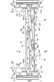
図7等に示すように、左脚本体(6)は、その上端部が、横断面コ字型のブラケット(66)を介して、左支柱(3)の左側壁(31)外面に取り付けられている。より詳細に言うと、まず、ブラケット(66)のベース壁(661)が、左支柱(3)の左側壁(31)外面に、複数組のボルト・ナット等によって接合固定され、次いで、ブラケット(66)のベース壁(661)の前後縁から左方にのびる前後壁(662)どうしの間に、左脚本体(6)の上端部が挿入されて、ブラケット(66)の前後壁(662)および左脚本体(6)の前後壁(62)を緩く貫通させられた回動ボルト(67)の先端にナット(68)がねじ嵌められることにより、左脚本体(6)が、左支柱(3)に開閉自在に取り付けられている(図7参照)。
図4に示すように、左脚本体(6)は、左支柱(3)と重なる閉じた状態において、その下端が左支柱(3)の下端とほぼ同一レベルに位置するように、左支柱(3)に取り付けられている。
左脚本体(6)の上端部には、その上端面を覆うように、キャップ(69)が装着されている。キャップ(69)は、例えば合成樹脂製であって、障害物との接触時にその力を逃がすように、片流れ屋根形の形状を有するものとなされている。
The left leg body (6) is made of a material such as aluminum, and has a vertical left side wall (61) and a front and rear wall (62) extending rightward from the front and rear edges of the left side wall (61). It is a substantially U-shaped one (see FIG. 5 etc.).
On the outer surface of the left side wall (61), two guide walls (63) projecting leftward are formed at an interval in the front-rear direction. At the front end portions of the two front and rear guide walls (63), there are provided fitting convex portions (64) bent outward in the front-rear direction so as to be opposite to each other.
A portion between the guide walls (63) of the left side wall (61) is slightly recessed to the right as compared with the both side portions. In the middle of the left and right widths of both guide walls (63), there are provided vertical ridges that project short so as to face each other, and between these vertical ridges and the portion between the guide walls (63) of the left side wall (61). An internal enlarged groove (65) is formed.
As shown in FIG. 7 and the like, the left leg body (6) has an upper end attached to the outer surface of the left wall (31) of the left column (3) via a bracket (66) having a U-shaped cross section. ing. More specifically, first, the base wall (661) of the bracket (66) is joined and fixed to the outer surface of the left wall (31) of the left column (3) by a plurality of bolts and nuts, etc. The upper end of the left leg body (6) is inserted between the front and rear walls (662) extending leftward from the front and rear edges of the base wall (661) of 66), and the front and rear walls (662) of the bracket (66) The nut (68) is screwed onto the tip of the rotating bolt (67) loosely passed through the front and rear walls (62) of the left leg body (6), so that the left leg body (6) It is attached to 3) so that it can be opened and closed (see FIG. 7).
As shown in FIG. 4, the left leg body (6) has a left strut (6) in a closed state where it overlaps with the left strut (3) so that its lower end is positioned at substantially the same level as the lower end of the left strut (3). It is attached to 3).
A cap (69) is attached to the upper end of the left leg body (6) so as to cover the upper end surface. The cap (69) is made of, for example, a synthetic resin, and has a single-flow roof shape so that the force is released when it comes into contact with an obstacle.
左開閉ロック装置(12)は、左支持バー(11)に長さ方向に間隔をおいて形成されている複数の係合部(13)と、スリーブ(9)内に前後方向にのびる揺動軸を中心として揺動自在に組み込まれかつ先端部に左支持バー(11)の係合部(13)に下方から係り止められる係合部(141a)を有しているロック爪(141)と、ロック爪(141)をその係合部(141a)が左支持バー(11)の係合部(13)に係り止められる方向に向かって付勢する弾性部材(15)と、ロック爪(141)の基端部に連なってロック爪(141)と反対方向にのびるとともにスリーブ(9)の底壁(92)に形成された連通窓(921)を通じて下方に突出させられており、上方に押圧することにより弾性部材(15)の弾性力に抗してロック爪(141)をその係合部(141a)が左支持バー(11)の係合部(13)から外れる方向に揺動させる操作レバー(142)とを備えている。
左支持バー(11)の係合部は、左支持バー(11)の底壁に長さ方向に間隔をおいて形成されている左右2つの係合孔(13)よりなる。なお、係合孔の数は3つ以上としてもよく、それによって脚本体の開度をより多段階に調整することが可能となる。
図8や図9等に示すように、ロック爪(141)、弾性部材(15)および操作レバー(142)は、ブラケット(16)内に組み込まれて、1つのユニットを構成している。
ブラケット(16)は、上方に開口した略U形の垂直横断面を有する折り曲げ金属片よりなり、スリーブ(9)の底壁(92)上面に重ねられる底壁(161)と、底壁(161)の前後縁から上方にのびかつスリーブ(9)の前後側壁(93)内面の下部に重ねられる前後立上り壁(162)とを備えている。ブラケット(16)の底壁(161)は、スリーブ(9)における底壁(92)上面の左端寄り部分に重ねられて、リベット等により同部分に接合固定されている。ブラケット(16)の前後各立上り壁(162)には、その中央部に挿通孔(162a)があけられている(図8参照)。また、これらの挿通孔(162a)に合致するように、スリーブ(9)の前後側壁(93)に挿通孔(図示略)があけられている。
ロック爪(141)および操作レバー(142)は、1つの揺動片(140)によって構成されている。揺動片(140)は、その長さの中間部に前後貫通状の挿通孔(140a)を有している。そして、揺動片(140)がブラケット(16)内に挿入されて、揺動片(140)の挿通孔(140a)、ブラケット(16)の前後立上り壁(162)の挿通孔(162a)、およびスリーブ(9)の前後側壁(93)の挿通孔にまたがって回動ボルト(21)が挿通され、その先端部にナット(22)がねじ嵌められることにより、揺動片(140)が回動ボルト(21)を中心としてブラケット(16)、ひいてはスリーブ(9)に揺動自在に取り付けられている。ロック爪(141)は、揺動片(140)の左右方向外側部分によって構成され、操作レバー(142)は、揺動片(140)の左右方向内側部分によって構成されている。
ロック爪(141)の係合部は、ロック爪(141)の先端部から上向きに折れ曲がった係合凸部(141a)よりなり、左支持バー(11)の各係合孔(13)に嵌め入れられて、同孔(13)の縁に係り止められるようになっている。
操作レバー(142)は、揺動片(140)の揺動軸(回動ボルト(21))からやや偏心した位置から、ロック爪(141)と反対向きにのびており、ロック爪(141)よりやや短いものとなされている。この操作レバー(142)は、ブラケット(16)の底壁(161)に形成された連通孔(161a)、およびこの連通孔(161a)と合致するようにスリーブ(9)の底壁(92)に形成された連通窓(921)を通じて、スリーブ(9)の下方に突出させられている。操作レバー(142)の下側面は、ロック解除時に手指で押される押圧部(142a)を構成している。押圧部(142a)には、手指の滑りを防止するために、横断面凹弧状をした複数本の水平溝(142b)が、左右方向に等間隔おきに形成されている(図8等参照)。
また、揺動片(140)には、操作レバー(142)の長さ中間部から操作レバー(142)の長さ方向と交差するように斜め下方に向かってのびる分岐片(143)が、操作レバー(142)と一体に設けられている。この分岐片(143)は、ロック爪(141)の係合凸部(141a)が支持バー(11)の係合孔(13)の縁に係り止められたロック状態において、分岐片(143)の先端が操作レバー(142)の先端とほぼ同一のレベルに並ぶとともに、分岐片(143)の先端と操作レバー(142)の先端との間にロック爪(141)の揺動軸(回動ボルト(21))が位置するように形成されている。
弾性部材(15)は、ねじりコイルばね(より詳細には、ダブルトーションばね)よりなり、そのコイル部が回動ボルト(21)の外側に嵌められた状態で、その両端部がブラケット(16)の底壁(161)とロック爪(141)との間に介在されている。このねじりコイルばね(15)によって、揺動片(140)を、その左右方向外側部分のロック爪(141)の係合凸部(141a)が支持バー(11)の係合孔(13)に嵌め込まれて同孔(13)の縁に係り止められるロック方向に付勢している。
The left open / close lock device (12) includes a plurality of engaging portions (13) formed in the left support bar (11) at intervals in the length direction, and a swing extending in the front-rear direction in the sleeve (9). A lock claw (141) which is incorporated so as to be swingable around an axis and has an engaging portion (141a) which is locked to the engaging portion (13) of the left support bar (11) from below at the distal end portion; An elastic member (15) for urging the lock claw (141) in a direction in which the engagement portion (141a) is locked to the engagement portion (13) of the left support bar (11); and the lock claw (141 ) Extends in the opposite direction to the lock claw (141) and protrudes downward through a communication window (921) formed in the bottom wall (92) of the sleeve (9), and presses upward. The operation of swinging the lock claw (141) against the elastic force of the elastic member (15) in a direction in which the engaging portion (141a) is disengaged from the engaging portion (13) of the left support bar (11) Lever (142).
The engagement portion of the left support bar (11) is composed of two left and right engagement holes (13) formed in the bottom wall of the left support bar (11) at intervals in the length direction. It should be noted that the number of engagement holes may be three or more, whereby the opening degree of the leg body can be adjusted in multiple stages.
As shown in FIGS. 8 and 9, etc., the lock claw (141), the elastic member (15), and the operation lever (142) are incorporated in the bracket (16) to constitute one unit.
The bracket (16) is formed of a bent metal piece having a substantially U-shaped vertical cross section opened upward, and includes a bottom wall (161) superimposed on an upper surface of the bottom wall (92) of the sleeve (9), and a bottom wall (161 ) And a front and rear rising wall (162) that extends upward from the front and rear edges of the sleeve (9) and overlaps the lower part of the inner surface of the front and rear side walls (93) of the sleeve (9). The bottom wall (161 ) of the bracket (16) is overlapped with a portion near the left end of the upper surface of the bottom wall (92) in the sleeve (9), and is joined and fixed to the same portion by a rivet or the like. An insertion hole (162a) is formed at the center of each of the front and rear rising walls (162) of the bracket (16) (see FIG. 8). Further, through holes (not shown) are formed in the front and rear side walls (93) of the sleeve (9) so as to match these through holes (162a).
The lock claw (141) and the operation lever (142) are constituted by one swing piece (140). The swing piece (140) has an insertion hole (140a) penetrating in the front-rear direction at an intermediate portion of the length. Then, the swing piece (140) is inserted into the bracket (16), the insertion hole (140a) of the swing piece (140), the insertion hole (162a) of the front and rear rising wall (162) of the bracket (16), The rotating bolt (21) is inserted across the insertion hole of the front and rear side walls (93) of the sleeve (9), and the nut (22) is screwed to the tip thereof, so that the swing piece (140) rotates. The moving bolt (21) is pivotally attached to the bracket (16) and eventually to the sleeve (9). The lock claw (141) is configured by a laterally outer portion of the swing piece (140), and the operation lever (142) is configured by a laterally inner portion of the swing piece (140).
The engaging portion of the lock claw (141) is composed of an engaging convex portion (141a) bent upward from the tip end portion of the lock claw (141), and is fitted in each engaging hole (13) of the left support bar (11). It is inserted and locked to the edge of the hole (13).
The operation lever (142) extends from the rocking shaft (rotating bolt (21)) of the rocking piece (140) slightly in the opposite direction to the lock claw (141). Somewhat short. The operation lever (142) includes a communication hole (161a) formed in the bottom wall (161) of the bracket (16), and a bottom wall (92) of the sleeve (9) so as to match the communication hole (161a). Through the communication window (921) formed on the sleeve, the sleeve (9) is projected downward. The lower surface of the operation lever (142) constitutes a pressing portion (142a) that is pressed with a finger when unlocking. In the pressing portion (142a), a plurality of horizontal grooves (142b) having a concave arc shape in cross section are formed at equal intervals in the left-right direction in order to prevent a finger from slipping (see FIG. 8 and the like). .
The swing piece (140) has a branch piece (143) extending obliquely downward from the middle part of the length of the operation lever (142) so as to intersect the length direction of the operation lever (142). It is provided integrally with the lever (142). This branch piece (143) is in a locked state in which the engaging projection (141a) of the lock claw (141) is locked to the edge of the engagement hole (13) of the support bar (11). The front end of the locking claw (141) is pivoted between the front end of the branch piece (143) and the front end of the operating lever (142). The bolt (21) is formed to be positioned.
The elastic member (15) is composed of a torsion coil spring (more specifically, a double torsion spring). The coil portion is fitted on the outer side of the rotating bolt (21), and both end portions of the elastic member (15) are brackets (16). Between the bottom wall (161) and the locking claw (141). By this torsion coil spring (15), the swinging piece (140) is engaged with the engaging projection (141a) of the locking claw (141) on the outer side in the left-right direction to the engaging hole (13) of the support bar (11). It is urged in the locking direction to be fitted and locked to the edge of the hole (13).