JP2017020249A - Underground structure receiving frame height adjustment device - Google Patents
Underground structure receiving frame height adjustment device Download PDFInfo
- Publication number
- JP2017020249A JP2017020249A JP2015138854A JP2015138854A JP2017020249A JP 2017020249 A JP2017020249 A JP 2017020249A JP 2015138854 A JP2015138854 A JP 2015138854A JP 2015138854 A JP2015138854 A JP 2015138854A JP 2017020249 A JP2017020249 A JP 2017020249A
- Authority
- JP
- Japan
- Prior art keywords
- receiving frame
- height
- piece
- underground structure
- main body
- Prior art date
- Legal status (The legal status is an assumption and is not a legal conclusion. Google has not performed a legal analysis and makes no representation as to the accuracy of the status listed.)
- Granted
Links
Images

Landscapes
- Underground Structures, Protecting, Testing And Restoring Foundations (AREA)
Abstract
【課題】地下構造物用受枠高さ調整における、施工現場における思い込みや勘違いによる施工ミスを防止する。【解決手段】地下構造物の開口部を塞ぐ蓋体を受け支える受枠15と地下構造物との間に介在し、受枠上端の高さを路面の高さに合わせて調整するための装置として、地下構造物に植設された複数個のアンカーボルト18に夫々取り付ける高さ調整駒を具え、高さ調整駒は受枠15を支える駒本体32と、駒本体32をアンカーボルト18の任意の高さに配置するために駒本体32と一体に設けられた、アンカーボルトに螺合するメネジ部を有して構成され、駒本体32は受枠の下面に接する曲面から成る支持面21を上部に有している。【選択図】図3An object of the present invention is to prevent construction mistakes due to assumptions or misunderstandings at the construction site in adjusting the height of a receiving frame for underground structures. As an apparatus for interposing between a receiving frame 15 that supports a lid that closes an opening of an underground structure and an underground structure, and adjusting the height of the upper end of the receiving frame in accordance with the height of a road surface, A height adjusting piece to be attached to each of the plurality of anchor bolts 18 installed in the underground structure is provided. The height adjusting piece has a piece main body 32 for supporting the receiving frame 15 and the piece main body 32 at an arbitrary height of the anchor bolt 18. The main body 32 has a support surface 21 formed of a curved surface that is in contact with the lower surface of the receiving frame. ing. [Selection] Figure 3
Description
本発明は、地下構造物の開口部を塞ぐ蓋体を受け支える受枠と地下構造物との間に介在し、受枠上端の高さを路面の高さに合わせて調整するための装置に関するものである。 The present invention relates to an apparatus that is interposed between a receiving frame that supports a lid that closes an opening of an underground structure and the underground structure, and adjusts the height of the upper end of the receiving frame according to the height of the road surface. is there.
受枠高さの調整は、地下構造物に植設された複数個のアンカーボルトに取り付ける高さ調整駒の高さを夫々変え、受枠上端の高さを路面の高さに合わせることを目的として行なわれる。受枠は高さ調整された後、アンカーボルトに螺合するナットを用いてフランジ部分にて最終的に緊締される。受枠を複数個のナットで締めすぎるなど適切に緊締できていない場合、受枠に変形を生じることがあり、変形を生じているテーパー嵌合蓋では、鉄蓋でマンホール開口を閉じたときに鉄蓋が受枠に食い込むことができず、がたつきを生じることとなる。 The height of the receiving frame is adjusted for the purpose of changing the height of the height adjusting pieces attached to the plurality of anchor bolts planted in the underground structure to match the height of the upper end of the receiving frame with the height of the road surface. . After the height of the receiving frame is adjusted, the receiving frame is finally tightened at the flange portion using a nut screwed to the anchor bolt. If the receiving frame is not properly tightened with multiple nuts, for example, the receiving frame may be deformed. For tapered fitting lids that are deformed, when the manhole opening is closed with the iron lid, the iron lid Can not bite into the receiving frame, causing rattling.
このため、受枠のフランジを曲面で支持する発明、考案が提案された。例えば、実開平3−108038号、実開平3−108039号、特開2001−182727号などはそれに該当する。上記実開平3−108039号にはレベル調整ブロックの上端を突曲面としたことで、受枠が傾くときには突曲面状で支持点が移動するので、傾斜に倣うように突曲面部分が受枠のフランジ下面を支持する、と記載されている(第3頁右欄)。しかながら取扱説明書を良く読まず、施工現場の勝手な判断で施工された結果、調整部材を用いているにも拘らず受枠が変形しガタツキを生じているものが散見されるようになった。 For this reason, an invention and a device for supporting the flange of the receiving frame with a curved surface have been proposed. For example, Japanese Utility Model Laid-Open Nos. 3-108038, 3-108039, and Japanese Patent Application Laid-Open No. 2001-182727 correspond to them. In the above Japanese Utility Model Laid-Open No. 3-108039, the upper end of the level adjustment block is formed as a projecting curved surface, so that when the receiving frame tilts, the support point moves in a projecting curved shape, so that the projecting curved surface portion follows the inclination of the flange lower surface of the receiving frame (Right column on page 3). However, without reading the instruction manual carefully, as a result of construction at the discretion of the construction site, there were some cases where the receiving frame was deformed and rattled despite the use of adjustment members. .
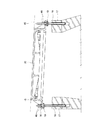
図6は上記従来技術を説明するもので、図中aは受枠、bは地下構造物、cはアンカーボルト、dは調整部材を示しており、その片側は曲面e、他の片側は平面fによってそれぞれ形成されている。図6Aは曲面eにてフランジgの下面を支持しており、正しい使用法である。ところが、図6Bに示すように調整部材dを上下逆に配置した誤った使用法で施工されることがある。それも或る程度の頻度で見出されることが、地下構造物の補修によって次第に明らかになって来た。 FIG. 6 illustrates the above-described prior art, in which a is a receiving frame, b is an underground structure, c is an anchor bolt, d is an adjustment member, one side thereof is a curved surface e, and the other side is a plane f. Are formed respectively. In FIG. 6A, the lower surface of the flange g is supported by the curved surface e, which is a correct usage. However, as shown in FIG. 6B, it may be constructed by an incorrect usage method in which the adjustment member d is disposed upside down. It has gradually become clear by the repair of underground structures that it is found at a certain frequency.
調整部材dの上下を間違えた施工ミスの場合、調整部材dの平面fが受枠下面の平面と接触し、その状態では変形防止機能が全く機能しないばかりか、鉄蓋をガタつかせる原因となる。また、調整部材dの平面fと受枠下面の平面との接触部iは点接触となるか又はスパナ掛けの直線部で接触したときは線接触となる。その状態でナットhを締め付け過ぎると、ボルト中心軸線から離れた上記接触部iでフランジgを支持しているので、ナットhを締め付けるに伴って受枠aに大きな曲げモーメントが作用し、図6Bに鎖線で示したように変形が発生する。この変形は微小なものであるが、機械加工された鉄蓋と受枠のテーパー嵌合を妨げ、その結果、鉄蓋のガタツキを招く原因となる。 In the case of a construction mistake in which the adjustment member d is upside down, the flat surface f of the adjustment member d comes into contact with the flat surface of the lower surface of the receiving frame. . Further, the contact portion i between the flat surface f of the adjusting member d and the flat surface of the lower surface of the receiving frame is a point contact, or a line contact when contacting with a straight portion with a spanner. If the nut h is tightened too much in this state, the flange g is supported by the contact portion i away from the center axis of the bolt, so that a large bending moment acts on the receiving frame a as the nut h is tightened. Deformation occurs as indicated by the chain line. Although this deformation is minute, it prevents the machined iron lid and the receiving frame from being taper-fitted, resulting in looseness of the iron lid.
本発明は前記の点に鑑みなされたもので、その課題は、地下構造物用受枠高さ調整において、施工現場における思い込みや勘違いによる施工ミスを防止することである。また、本発明の他の課題は、経験年数の多寡に関わらず、更にはテーパー嵌合蓋の変形防止機能そのものを知らない作業者が施工しても、変形防止機能を確実に発揮させることができるようにすることである。また、本発明の他の課題は、傾斜の大小に対応した高さ調整が可能な地下構造物用受枠高さ調整装置を提供することである。 This invention is made | formed in view of the said point, The subject is preventing the construction mistake by the assumption in a construction site, or the misunderstanding in the receiving frame height adjustment for underground structures. Another object of the present invention is to ensure that the anti-deformation function can be exerted reliably even if an operator who does not know the anti-deformation function of the taper fitting lid itself is constructed regardless of the number of years of experience. Is to be able to do it. Moreover, the other subject of this invention is providing the receiving frame height adjustment apparatus for underground structures in which the height adjustment corresponding to the magnitude of inclination is possible.
前記の課題を解決するため、本発明は、地下構造物の開口部を塞ぐ蓋体を受け支える受枠と地下構造物との間に介在し、受枠上端の高さを路面の高さに合わせて調整するための装置について、地下構造物に植設された複数個のアンカーボルトに夫々取り付ける高さ調整駒を具え、高さ調整駒は受枠を支える駒本体と、駒本体をアンカーボルトの任意の高さに配置するために駒本体と一体に設けられた、アンカーボルトに螺合するメネジ部を有して構成され、駒本体は受枠の下面に接する曲面から成る支持面を駒本体自体の上部と下部に有するものとするという手段を講じたものである。 In order to solve the above problems, the present invention is interposed between a receiving frame that supports a lid that closes an opening of an underground structure and the underground structure, and adjusts the height of the upper end of the receiving frame to the height of the road surface. A device for adjusting includes a height adjusting piece to be attached to each of a plurality of anchor bolts installed in the underground structure. The height adjusting piece includes a frame body that supports the receiving frame, and the frame body is an arbitrary anchor bolt. It is provided with a female threaded part that is screwed into an anchor bolt, which is provided integrally with the frame body for placement at a height, and the frame body has a support surface consisting of a curved surface in contact with the lower surface of the receiving frame. And the means to have at the bottom.
本発明に係る地下構造物用受枠高さ調整装置も高さ調整駒という部材を使用し、受枠上端の高さを路面の高さに合わせるものであるから、調整方法に付いては従来の場合と共通である。その構成において、本発明に係る調整装置は、駒本体が受枠の下面に接する曲面から成る支持面を駒本体自体の上部と下部に有することを特徴とする。換言すれば、駒本体から平面を除去し、支持面を曲面からのみ構成することによって、作業者に思い込みや勘違いがあっても施工ミスにつながらないように改良を施したものである。 The receiving frame height adjusting device for underground structures according to the present invention also uses a member called a height adjusting piece, and adjusts the height of the upper end of the receiving frame to the height of the road surface. And in common. In this configuration, the adjusting device according to the present invention is characterized in that the piece body has support surfaces formed of curved surfaces in contact with the lower surface of the receiving frame at the upper and lower portions of the piece body itself. In other words, the plane is removed from the main body of the piece, and the support surface is configured only from the curved surface, so that an improvement is made so as not to lead to a construction error even if the operator thinks or misunderstands.
本発明に係る調整装置では、上部と下部の支持面を構成する曲面が球面によって構成され、駒本体上部の支持面を構成する球面の半径と、駒本体下部の支持面を構成する球面の半径とは同一寸法であるか又は異なる寸法であるという構成を取ることができる。これにより、曲面を球面に形成することができるので、球面以外の曲面その他の形状よりも容易に形成される。 In the adjusting device according to the present invention, the curved surfaces constituting the upper and lower support surfaces are constituted by spherical surfaces, the radius of the spherical surface constituting the support surface of the upper part of the piece body, and the radius of the spherical surface constituting the support surface of the lower part of the piece body Can be configured to have the same dimensions or different dimensions. Thereby, since a curved surface can be formed in a spherical surface, it is formed more easily than a curved surface other than a spherical surface or other shapes.
上部と下部の支持面のどちらで受枠の下面に接しても、それぞれの球面の中心で受枠を支持するので、ナットによる締め付け力が大きくなっても受枠に作用する変形力はほとんど変わらない。しかし、受枠の傾斜がきつい場合、受枠下面と球面との接触部が外周側にずれ、受枠に作用する変形力の増す場合がある。このとき、球面の小さい方を用いると球面の接触部が外方へずれる量が小さくなり、受枠に作用する変形力の発生を防止又は最小に抑制することができる。 Regardless of which of the upper and lower support surfaces is in contact with the lower surface of the receiving frame, the receiving frame is supported at the center of each spherical surface. Therefore, even if the tightening force by the nut increases, the deformation force acting on the receiving frame hardly changes. However, when the inclination of the receiving frame is tight, the contact portion between the lower surface of the receiving frame and the spherical surface may shift to the outer peripheral side, and the deformation force acting on the receiving frame may increase. At this time, when the smaller spherical surface is used, the amount by which the spherical contact portion is displaced outward is reduced, and the generation of the deformation force acting on the receiving frame can be prevented or suppressed to a minimum.
駒本体として、エンジニアリングプラスチックスを含む樹脂の成形品より成り、メネジ部は上記成形品の成形時に同時に成形されているか又は別部材のナットを駒本体成形時にインサート成形することによって一体化されているものは好ましい構成である。メネジ部が上記成形品と時に同時に成形されている構成であれば、別部材のナットは不要である。別にナットを用いてインサート成形することは容易であり、それぞれに適した材質から成るものを使用することができる。 The piece body is made of a resin molded product containing engineering plastics, and the female screw part is formed at the same time when the molded product is formed, or is integrated by insert molding a nut of another member at the time of forming the piece body. The one is a preferred configuration. If the female thread portion is formed at the same time as the molded product, a separate nut is not necessary. Separately, it is easy to insert-mold using a nut, and it is possible to use one made of a material suitable for each.
また、駒本体上部の支持面と下部の支持面との間が最大径の中間部分になっており、駒本体を回転させる際の手掛かりとなる係止部が上記中間部分に形成されている構成は、本発明にとって好ましいものである。いわゆるスパナ掛けに相当する構成であるけれども、それらの工具類を用いることなく、手で操作して高さ調整駒を任意の高さ位置に移動させることができる。 In addition, the intermediate portion having the maximum diameter is formed between the upper support surface and the lower support surface of the piece main body, and a locking portion serving as a clue when the piece main body is rotated is formed in the intermediate portion. Is preferred for the present invention. Although it is a structure corresponding to a so-called spanner hook, the height adjusting piece can be moved to an arbitrary height position by operating by hand without using these tools.
本発明は以上のように構成され、かつ、作用するものであるから、地下構造物用受枠高さ調整において、高さ調整駒を取り付ける向きに拘らず本来の機能を発揮し得るので、施工現場における思い込みや勘違いがあっても、施工ミスを防止することができるという効果を奏する。また、本発明によれば、経験年数の多寡に関わらず、更にはテーパー嵌合蓋の変形防止機能そのものを知らない作業者が施工しても、変形防止機能を確実に発揮させることができる。また、本発明によれば、傾斜の大小に対応した高さ調整が可能な地下構造物用受枠高さ調整装置を提供することができる。 Since the present invention is configured and operates as described above, in the adjustment of the receiving frame height for the underground structure, the original function can be exhibited regardless of the direction in which the height adjusting piece is attached. Even if there are misunderstandings and misunderstandings, there is an effect that construction errors can be prevented. Further, according to the present invention, regardless of the number of years of experience, even when an operator who does not know the function of preventing deformation of the taper fitting lid itself performs construction, the function of preventing deformation can be reliably exhibited. Moreover, according to this invention, the receiving frame height adjustment apparatus for underground structures which can adjust the height corresponding to the magnitude of inclination can be provided.
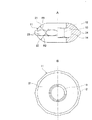
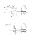
以下、図示の実施形態について本発明をより詳細に説明する。図1は本発明に係る地下構造物用受枠高さ調整装置10の例1に関するもので、高さ調整駒11は駒本体12と、駒本体12と一体に設けられたメネジ部13とを有して構成されている。例1の場合、駒本体12は比較的扁平な形態を有し、その内部にナット14が一体に設けられており、ナットのメネジをメネジ部13として使用している。
Hereinafter, the present invention will be described in more detail with reference to illustrated embodiments. FIG. 1 relates to Example 1 of a receiving frame
図3以下に示したように、駒本体12は受枠15をフランジ部16にて支えるもので、駒本体12をアンカーボルト18の任意の高さに配置するためメネジ部13が設けられている。アンカーボルト18は受枠15の下部に位置する地下構造物17に植設されており、受枠15には、アンカーボルト18を通すために、ボルト孔19が形成されている。アンカーボルト18とボルト孔19は、円形マンホールの場合数個程度設けられるが、周方向に均等な間隔で三箇所に設けるのが一般的である。
As shown in FIG. 3 and the subsequent figures, the piece
上記駒本体12はエンジニアリングプラスチックス又はその他の樹脂を素材として、射出成形によって成形形成されている。従って、ナット14はインサート成形法によって、射出成形時に駒本体12と一体に形成されている。エンジニアリングプラスチックスを用いて駒本体12を型成形するときに同時にメネジ部13を型成形することで、ナット14を使用しない選択も可能であるが、どちらを採用するかについては設計上の要求やコスト等の条件によって選択することができる。
The
本発明において、駒本体12は受枠15の下面に接する曲面から成る支持面21、22を駒本体自体の上部と下部に有している。駒本体12は比較的扁平な形態を有するので、面と呼べる部分を上下それぞれに有するが、どちらを上部或いは下部というかを強いて決める必要性はないので、説明の便宜上の区別であると考えて良い。
In the present invention, the piece
例1において、支持面21、22は、それぞれを構成する曲面が球面によって構成されている。そして、上部の支持面21を構成する球面の半径R1と、下部の支持面22を構成する球面の半径R2は同一寸法R1=R2に設定されている。従って、図1に示した例1の場合、上下支持面21、22の差は全くないことになるので、高さ調整駒11の向きを間違えて取り付けるということがそもそも起こらない。
In Example 1, the support surfaces 21 and 22 are each configured by a spherical surface. The radius R1 of the spherical surface constituting the
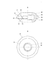
これに対し、図2に示した例2では、上部の支持面21を構成する球面の半径R1と、下部の支持面23を構成する球面の半径R3は異なる寸法R1≠R3に設定されている。また、例2において、高さ調整駒31は駒本体32と、駒本体32と一体に設けられたメネジ部33が設けられているナット34を有して構成されており、その基本的構成は例1の場合と同じである。
On the other hand, in Example 2 shown in FIG. 2, the radius R1 of the spherical surface constituting the
例1及び例2において、駒本体上部の支持面21と下部の支持面22との間が最大径の中間部分24になっており、この中間部分24に駒本体12、32を回転させる際の手掛かりとなる係止部25が形成されている。係止部25は実施例1、2とも12角形の平面形状を有している。係止部25は手で掴んで回す作業を容易にする形態であれば、ローレット状の形態でも良い。
In Example 1 and Example 2, the
何れの形状を選択するにしても、施工時に片手で受枠15を持ち上げて高さ調整駒11から離し、指で回すことで、作業者は工具類を使わずに容易かつスピーディに高さを調整することができる。なお、ネジ精度等によってはスムーズに回らないこともあり、その場合はレンチ等の工具を使用して回すことになるので、係止部25は多角形状である方が良い。
Regardless of which shape is selected, the operator can easily and quickly adjust the height without using tools by lifting the receiving
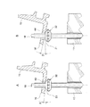
次に、本発明に係る地下構造物用受枠高さ調整装置を用いる高さ調整について、図3ないし図5を参照して説明する。以下、例2の大きい半径R1を有する支持面21を大きい球面と呼び、小さい半径R3を有する支持面23を小さい球面と呼ぶことがある。なお、図3、図4には示していないが、図5のようにフランジ16は止めナット46によって締め付けられる。
Next, height adjustment using the receiving frame height adjusting device for an underground structure according to the present invention will be described with reference to FIGS. 3 to 5. Hereinafter, the
上記図3Aは、その大きい半径R1を有する支持面21が上部に位置する施工であり、受枠15の傾斜角θが相対的に小さい場合に適している。この場合、フランジ16の下面に対する駒本体32の支持部41はボルト中心軸線に対して至近の位置にあるので、ナット14を締め付けても受枠16に大きな曲げモーメントが作用することはない。
FIG. 3A is a construction in which the
他方、図3Bは小さい半径R3を有する支持面23が上部に位置する施工であり、受枠15の傾斜角θが相対的に大きい場合に適している。この場合も、フランジ16の下面に対する駒本体32の支持部42はボルト中心軸線に対して、なお至近の位置にあるので、ナット14を締め付けても受枠16に大きな曲げモーメントが作用することはない。上記の高さ調整駒31の使用方法は、本発明において想定している一般的な(正しい)使用方法である。
On the other hand, FIG. 3B is a construction in which the
これに対して、図4は高さ調整駒31を図3と逆向きにした使用方法を示している。図4Aは受枠15の傾斜角θが相対的に小さいにも拘らず、小さい半径R3を有する支持面23が上部に位置する施工である。この場合、フランジ16の下面に対する駒本体32の支持部43は、ボルト中心軸線から図3Aにおける支持部41よりも僅かに離れるが小さい球面上にあるため、過剰な曲げモーメントを生ずるには至らない。
On the other hand, FIG. 4 shows a usage method in which the
また、図4Bは、受枠15の傾斜角θが相対的に大きい場合に、大きい半径R1を有する支持面21が上部に位置する施工である。この場合、フランジ16の下面に対する駒本体32の支持部44は、ボルト中心軸線から図3Bにおける支持部42よりも僅かに離れるが大きい球面上にあるため、過剰な曲げモーメントを生ずるには至らない。図4の例は想定した使用法と相違しておりいわば誤組み付けになるが、本発明によれば、想定通りとはいえない使用法で施工しても鉄蓋と受枠のテーパー嵌合を妨げるような問題を引き起こすことがない。
FIG. 4B shows a construction in which the
本発明の受枠高さ調整装置10はこのような構成を有するので、図5に示すように、地下構造物用蓋体20を受け支える受枠15の下部に位置する地下構造物17との間に介在することで、受枠上端の高さを路面45の高さに合わせて調整する作業がより容易にできるとともに、施工現場における思い込みや勘違いによる施工ミスを回避して、不具合の発生を未然に防止することができる。
Since the receiving frame
なお、上部と下部の支持面21、22、23は球面で構成されるもののみを示したが、非球面で構成される支持面であっても本発明に適用し得ることは明らかである。また、球面で構成された本発明の実施形態では、球面の中心をアンカーボルト18の中心軸線から離した例を説明した。しかし、球面の中心がボルト中心軸線と一致する支持面によって本発明に係る高さ調整装置を構成することも当然可能である。
Although the upper and lower support surfaces 21, 22, and 23 are only spherical surfaces, it is apparent that the present invention can also be applied to support surfaces that are aspherical. Further, in the embodiment of the present invention configured with a spherical surface, the example in which the center of the spherical surface is separated from the central axis of the
10 地下構造物用受枠高さ調整装置
11、31 高さ調整駒
12、32 駒本体
13、33 メネジ部
14、34 ナット
15 受枠
16 フランジ部
17 地下構造物
18 アンカーボルト
19 ボルト孔
20 蓋体
21 上部支持面
22、23 下部支持面
24 中間部分
25 係止部
41、42、43、44 支持部
45 路面
DESCRIPTION OF
24
このため、受枠のフランジを曲面で支持する発明、考案が提案された。例えば、実開平3−108038号、実開平3−108039号、特開2001−182727号などはそれに該当する。上記実開平3−108039号にはレベル調整ブロックの上端を突曲面としたことで、受枠が傾くときには突曲面状で支持点が移動するので、傾斜に倣うように突曲面部分が受枠のフランジ下面を支持する、と記載されている(第10頁第9〜12行)。しかながら取扱説明書を良く読まず、施工現場の勝手な判断で施工された結果、調整部材を用いているにも拘らず受枠が変形しガタツキを生じているものが散見されるようになった。
For this reason, an invention and a device for supporting the flange of the receiving frame with a curved surface have been proposed. For example, Japanese Utility Model Laid-Open Nos. 3-108038, 3-108039, and Japanese Patent Application Laid-Open No. 2001-182727 correspond to them. In the above Japanese Utility Model Laid-Open No. 3-108039, the upper end of the level adjustment block is formed as a projecting curved surface, so that when the receiving frame tilts, the support point moves in a projecting curved shape, so that the projecting curved surface portion follows the inclination of the flange lower surface of the receiving frame (
前記の課題を解決するため、本発明は、地下構造物の開口部を塞ぐ蓋体を受け支える受枠と地下構造物との間に介在し、受枠上端の高さを路面の高さに合わせて調整するための装置について、地下構造物に植設された複数個のアンカーボルトに夫々取り付ける高さ調整駒を具え、高さ調整駒は受枠を支える駒本体と、駒本体をアンカーボルトの任意の高さに配置するために駒本体と一体に設けられた、アンカーボルトに螺合するメネジ部を有して構成され、駒本体は受枠の下面に接する曲面から成る支持面を駒本体自体の上部と下部に有し、駒本体上部の支持面と下部の支持面との間が、上記曲面より外方へ突出する最大径の中間部分になっており、駒本体を回転させる際の手掛かりとなる係止部が上記中間部分に形成するという手段を講じたものである。
In order to solve the above problems, the present invention is interposed between a receiving frame that supports a lid that closes an opening of an underground structure and the underground structure, and adjusts the height of the upper end of the receiving frame to the height of the road surface. A device for adjusting includes a height adjusting piece to be attached to each of a plurality of anchor bolts installed in the underground structure. The height adjusting piece includes a frame body that supports the receiving frame, and the frame body is an arbitrary anchor bolt. It is provided with a female threaded part that is screwed into an anchor bolt, which is provided integrally with the frame body for placement at a height, and the frame body has a support surface consisting of a curved surface in contact with the lower surface of the receiving frame. Between the support surface of the upper part of the piece body and the support surface of the lower part is the middle part of the maximum diameter that protrudes outward from the curved surface, which is a clue when rotating the piece body take measures that the locking portion is formed in the intermediate portion It is intended.
Claims (4)
地下構造物に植設された複数個のアンカーボルトに夫々取り付ける高さ調整駒を具え、
高さ調整駒は受枠を支える駒本体と、駒本体をアンカーボルトの任意の高さに配置するために駒本体と一体に設けられた、アンカーボルトに螺合するメネジ部を有して構成され、
駒本体は受枠の下面に接する曲面から成る支持面を駒本体自体の上部と下部に有している
地下構造物用受枠高さ調整装置。 A device for interposing between the receiving frame that supports the lid that closes the opening of the underground structure and the underground structure, and adjusting the height of the upper end of the receiving frame according to the height of the road surface,
Height adjustment pieces to be attached to each of the plurality of anchor bolts planted in the underground structure,
The height adjustment piece has a piece main body that supports the receiving frame, and a female screw portion that is provided integrally with the piece main body and is screwed to the anchor bolt so as to arrange the piece main body at an arbitrary height of the anchor bolt. ,
The frame main body is a receiving frame height adjusting device for an underground structure having a support surface made of a curved surface in contact with the lower surface of the frame at the upper and lower portions of the frame main body itself.
請求項1記載の地下構造物用受枠高さ調整装置。 The curved surfaces constituting the upper and lower support surfaces are constituted by spherical surfaces, and the radius of the spherical surface constituting the upper support surface and the radius of the spherical surface constituting the lower support surface are the same or different dimensions. The receiving frame height adjusting device for an underground structure according to claim 1.
請求項1記載の地下構造物用受枠高さ調整装置。 The piece body is formed of a resin molded product containing engineering plastics, and the female screw portion is formed at the same time when the molded product is formed, or is integrated by insert molding a nut of a separate member at the time of forming the piece body. Item 1. A receiving frame height adjusting device for an underground structure according to Item 1.
請求項1記載の地下構造物用受枠高さ調整装置。 2. An intermediate portion having a maximum diameter is formed between the upper support surface and the lower support surface of the piece body, and a locking portion serving as a clue when the piece body is rotated is formed in the intermediate portion. The receiving frame height adjustment apparatus for underground structures as described.
Priority Applications (1)
| Application Number | Priority Date | Filing Date | Title |
|---|---|---|---|
| JP2015138854A JP5847981B1 (en) | 2015-07-10 | 2015-07-10 | Underground structure receiving frame height adjustment device |
Applications Claiming Priority (1)
| Application Number | Priority Date | Filing Date | Title |
|---|---|---|---|
| JP2015138854A JP5847981B1 (en) | 2015-07-10 | 2015-07-10 | Underground structure receiving frame height adjustment device |
Publications (2)
| Publication Number | Publication Date |
|---|---|
| JP5847981B1 JP5847981B1 (en) | 2016-01-27 |
| JP2017020249A true JP2017020249A (en) | 2017-01-26 |
Family
ID=55176116
Family Applications (1)
| Application Number | Title | Priority Date | Filing Date |
|---|---|---|---|
| JP2015138854A Active JP5847981B1 (en) | 2015-07-10 | 2015-07-10 | Underground structure receiving frame height adjustment device |
Country Status (1)
| Country | Link |
|---|---|
| JP (1) | JP5847981B1 (en) |
Cited By (1)
| Publication number | Priority date | Publication date | Assignee | Title |
|---|---|---|---|---|
| JP7652017B2 (en) | 2021-08-30 | 2025-03-27 | 沖電気工業株式会社 | Chassis |
Families Citing this family (1)
| Publication number | Priority date | Publication date | Assignee | Title |
|---|---|---|---|---|
| JP3286738B2 (en) | 1994-04-13 | 2002-05-27 | 荘八 小杉 | Method for producing unevenly patterned article and unevenly patterned article |
Family Cites Families (7)
| Publication number | Priority date | Publication date | Assignee | Title |
|---|---|---|---|---|
| JPH0354186Y2 (en) * | 1986-01-18 | 1991-11-28 | ||
| JP2502400Y2 (en) * | 1990-02-16 | 1996-06-19 | 日之出水道機器株式会社 | Level adjustment device for receiving frames for underground structures |
| JPH03244809A (en) * | 1990-02-22 | 1991-10-31 | Nippon Avionics Co Ltd | Bolts, nuts and fastening structures |
| JPH042702U (en) * | 1990-04-24 | 1992-01-10 | ||
| JP3660594B2 (en) * | 2001-01-12 | 2005-06-15 | 長島鋳物株式会社 | Bolt end protection device for underground structures |
| JP4004869B2 (en) * | 2002-06-24 | 2007-11-07 | Ntn株式会社 | Injection mold of resin nut for feed screw device and manufacturing method |
| JP5007142B2 (en) * | 2007-04-03 | 2012-08-22 | Ntn株式会社 | Resin nut and sliding screw device |
-
2015
- 2015-07-10 JP JP2015138854A patent/JP5847981B1/en active Active
Cited By (1)
| Publication number | Priority date | Publication date | Assignee | Title |
|---|---|---|---|---|
| JP7652017B2 (en) | 2021-08-30 | 2025-03-27 | 沖電気工業株式会社 | Chassis |
Also Published As
| Publication number | Publication date |
|---|---|
| JP5847981B1 (en) | 2016-01-27 |
Similar Documents
| Publication | Publication Date | Title |
|---|---|---|
| US4384812A (en) | Screw and screw forming tool | |
| CN106211789A (en) | Screw member, fastening structure and the attachment structure of solar panel buoyancy aid | |
| KR20130041755A (en) | Work pallet positioning and affixing device | |
| JP3187298U (en) | Double lock nut | |
| JP5847981B1 (en) | Underground structure receiving frame height adjustment device | |
| JP6329772B2 (en) | Lower member fixing device and fluid control device including the same | |
| US6805488B2 (en) | Linear guide rail holding device | |
| JP2013087947A (en) | Crossbolt locking combination nut | |
| JP2018521281A (en) | Fasteners and fastener systems for soft materials | |
| JP2018514401A (en) | Dynamic clamping mechanism | |
| JP7125165B2 (en) | floor support | |
| US20170016219A1 (en) | Sink Drain Stopper Assembly | |
| JP4401162B2 (en) | Screw member tightening confirmation tool | |
| JP6186271B2 (en) | Lower member fixing device and fluid control device including the same | |
| JP6372016B2 (en) | Locking nut | |
| KR101750004B1 (en) | Tapping bolt with vertical support surface and manufacturing method for the same | |
| JP2018150976A (en) | Fastener and fastened state monitoring method | |
| CN206445575U (en) | Object Locator | |
| JP2015166274A (en) | screw jack | |
| JP5788581B1 (en) | A centering method in which the spherical shape is held at the opposite center of the conical groove at the tip. | |
| JP3223994U (en) | Laboratory stand | |
| US11536021B2 (en) | Adjustable plate support for a precast concrete panel | |
| US3161084A (en) | Machine tool turret | |
| JP3136345U (en) | Drum can lid clamp | |
| JP3792692B2 (en) | Bundle |
Legal Events
| Date | Code | Title | Description |
|---|---|---|---|
| TRDD | Decision of grant or rejection written | ||
| A01 | Written decision to grant a patent or to grant a registration (utility model) |
Free format text: JAPANESE INTERMEDIATE CODE: A01 Effective date: 20151110 |
|
| A61 | First payment of annual fees (during grant procedure) |
Free format text: JAPANESE INTERMEDIATE CODE: A61 Effective date: 20151125 |
|
| R150 | Certificate of patent or registration of utility model |
Ref document number: 5847981 Country of ref document: JP Free format text: JAPANESE INTERMEDIATE CODE: R150 |
|
| R250 | Receipt of annual fees |
Free format text: JAPANESE INTERMEDIATE CODE: R250 |
|
| R250 | Receipt of annual fees |
Free format text: JAPANESE INTERMEDIATE CODE: R250 |
|
| R250 | Receipt of annual fees |
Free format text: JAPANESE INTERMEDIATE CODE: R250 |
|
| R250 | Receipt of annual fees |
Free format text: JAPANESE INTERMEDIATE CODE: R250 |
|
| R250 | Receipt of annual fees |
Free format text: JAPANESE INTERMEDIATE CODE: R250 |
|
| R250 | Receipt of annual fees |
Free format text: JAPANESE INTERMEDIATE CODE: R250 |
|
| R250 | Receipt of annual fees |
Free format text: JAPANESE INTERMEDIATE CODE: R250 |
|
| R250 | Receipt of annual fees |
Free format text: JAPANESE INTERMEDIATE CODE: R250 |