JP2017018519A - Display device and computer program - Google Patents
Display device and computer program Download PDFInfo
- Publication number
- JP2017018519A JP2017018519A JP2015141083A JP2015141083A JP2017018519A JP 2017018519 A JP2017018519 A JP 2017018519A JP 2015141083 A JP2015141083 A JP 2015141083A JP 2015141083 A JP2015141083 A JP 2015141083A JP 2017018519 A JP2017018519 A JP 2017018519A
- Authority
- JP
- Japan
- Prior art keywords
- hand
- display
- image
- display device
- marker
- Prior art date
- Legal status (The legal status is an assumption and is not a legal conclusion. Google has not performed a legal analysis and makes no representation as to the accuracy of the status listed.)
- Pending
Links
- 238000004590 computer program Methods 0.000 title claims description 13
- 239000003550 marker Substances 0.000 claims abstract description 60
- 238000003384 imaging method Methods 0.000 claims abstract description 5
- 230000033001 locomotion Effects 0.000 claims description 50
- 238000000034 method Methods 0.000 description 21
- 230000008569 process Effects 0.000 description 19
- 238000012986 modification Methods 0.000 description 17
- 230000004048 modification Effects 0.000 description 15
- 238000010586 diagram Methods 0.000 description 10
- 230000006870 function Effects 0.000 description 10
- 230000003287 optical effect Effects 0.000 description 9
- 238000003860 storage Methods 0.000 description 9
- 238000000605 extraction Methods 0.000 description 8
- 210000003128 head Anatomy 0.000 description 8
- 210000003811 finger Anatomy 0.000 description 7
- 210000003813 thumb Anatomy 0.000 description 7
- 206010033799 Paralysis Diseases 0.000 description 6
- 230000000694 effects Effects 0.000 description 6
- 238000001514 detection method Methods 0.000 description 4
- 210000004932 little finger Anatomy 0.000 description 4
- 238000002360 preparation method Methods 0.000 description 4
- 208000037265 diseases, disorders, signs and symptoms Diseases 0.000 description 3
- 210000002683 foot Anatomy 0.000 description 3
- 210000004247 hand Anatomy 0.000 description 3
- 125000002066 L-histidyl group Chemical group [H]N1C([H])=NC(C([H])([H])[C@](C(=O)[*])([H])N([H])[H])=C1[H] 0.000 description 2
- 210000003423 ankle Anatomy 0.000 description 2
- 230000003190 augmentative effect Effects 0.000 description 2
- 230000014509 gene expression Effects 0.000 description 2
- 239000011521 glass Substances 0.000 description 2
- 210000000707 wrist Anatomy 0.000 description 2
- YMHOBZXQZVXHBM-UHFFFAOYSA-N 2,5-dimethoxy-4-bromophenethylamine Chemical compound COC1=CC(CCN)=C(OC)C=C1Br YMHOBZXQZVXHBM-UHFFFAOYSA-N 0.000 description 1
- 241000545067 Venus Species 0.000 description 1
- 230000008901 benefit Effects 0.000 description 1
- 230000005540 biological transmission Effects 0.000 description 1
- 239000011248 coating agent Substances 0.000 description 1
- 238000000576 coating method Methods 0.000 description 1
- 239000012141 concentrate Substances 0.000 description 1
- 210000004709 eyebrow Anatomy 0.000 description 1
- 210000001145 finger joint Anatomy 0.000 description 1
- 230000004907 flux Effects 0.000 description 1
- 230000006872 improvement Effects 0.000 description 1
- 239000004973 liquid crystal related substance Substances 0.000 description 1
- 238000004519 manufacturing process Methods 0.000 description 1
- 210000004197 pelvis Anatomy 0.000 description 1
- 238000011084 recovery Methods 0.000 description 1
- 230000009467 reduction Effects 0.000 description 1
- 230000008929 regeneration Effects 0.000 description 1
- 238000011069 regeneration method Methods 0.000 description 1
- 210000001525 retina Anatomy 0.000 description 1
- 238000004088 simulation Methods 0.000 description 1
Images


Classifications
-
- A—HUMAN NECESSITIES
- A61—MEDICAL OR VETERINARY SCIENCE; HYGIENE
- A61H—PHYSICAL THERAPY APPARATUS, e.g. DEVICES FOR LOCATING OR STIMULATING REFLEX POINTS IN THE BODY; ARTIFICIAL RESPIRATION; MASSAGE; BATHING DEVICES FOR SPECIAL THERAPEUTIC OR HYGIENIC PURPOSES OR SPECIFIC PARTS OF THE BODY
- A61H1/00—Apparatus for passive exercising; Vibrating apparatus ; Chiropractic devices, e.g. body impacting devices, external devices for briefly extending or aligning unbroken bones
-
- A—HUMAN NECESSITIES
- A61—MEDICAL OR VETERINARY SCIENCE; HYGIENE
- A61B—DIAGNOSIS; SURGERY; IDENTIFICATION
- A61B5/00—Measuring for diagnostic purposes; Identification of persons
- A61B5/103—Detecting, measuring or recording devices for testing the shape, pattern, colour, size or movement of the body or parts thereof, for diagnostic purposes
- A61B5/11—Measuring movement of the entire body or parts thereof, e.g. head or hand tremor, mobility of a limb
- A61B5/1124—Determining motor skills
- A61B5/1125—Grasping motions of hands
-
- G—PHYSICS
- G02—OPTICS
- G02B—OPTICAL ELEMENTS, SYSTEMS OR APPARATUS
- G02B27/00—Optical systems or apparatus not provided for by any of the groups G02B1/00 - G02B26/00, G02B30/00
- G02B27/01—Head-up displays
- G02B27/017—Head mounted
-
- G—PHYSICS
- G06—COMPUTING; CALCULATING OR COUNTING
- G06F—ELECTRIC DIGITAL DATA PROCESSING
- G06F3/00—Input arrangements for transferring data to be processed into a form capable of being handled by the computer; Output arrangements for transferring data from processing unit to output unit, e.g. interface arrangements
- G06F3/01—Input arrangements or combined input and output arrangements for interaction between user and computer
- G06F3/011—Arrangements for interaction with the human body, e.g. for user immersion in virtual reality
-
- G—PHYSICS
- G06—COMPUTING; CALCULATING OR COUNTING
- G06F—ELECTRIC DIGITAL DATA PROCESSING
- G06F3/00—Input arrangements for transferring data to be processed into a form capable of being handled by the computer; Output arrangements for transferring data from processing unit to output unit, e.g. interface arrangements
- G06F3/01—Input arrangements or combined input and output arrangements for interaction between user and computer
- G06F3/017—Gesture based interaction, e.g. based on a set of recognized hand gestures
-
- G—PHYSICS
- G06—COMPUTING; CALCULATING OR COUNTING
- G06T—IMAGE DATA PROCESSING OR GENERATION, IN GENERAL
- G06T19/00—Manipulating 3D models or images for computer graphics
- G06T19/006—Mixed reality
-
- G—PHYSICS
- G16—INFORMATION AND COMMUNICATION TECHNOLOGY [ICT] SPECIALLY ADAPTED FOR SPECIFIC APPLICATION FIELDS
- G16H—HEALTHCARE INFORMATICS, i.e. INFORMATION AND COMMUNICATION TECHNOLOGY [ICT] SPECIALLY ADAPTED FOR THE HANDLING OR PROCESSING OF MEDICAL OR HEALTHCARE DATA
- G16H20/00—ICT specially adapted for therapies or health-improving plans, e.g. for handling prescriptions, for steering therapy or for monitoring patient compliance
- G16H20/30—ICT specially adapted for therapies or health-improving plans, e.g. for handling prescriptions, for steering therapy or for monitoring patient compliance relating to physical therapies or activities, e.g. physiotherapy, acupressure or exercising
-
- A—HUMAN NECESSITIES
- A63—SPORTS; GAMES; AMUSEMENTS
- A63B—APPARATUS FOR PHYSICAL TRAINING, GYMNASTICS, SWIMMING, CLIMBING, OR FENCING; BALL GAMES; TRAINING EQUIPMENT
- A63B2214/00—Training methods
-
- G—PHYSICS
- G02—OPTICS
- G02B—OPTICAL ELEMENTS, SYSTEMS OR APPARATUS
- G02B27/00—Optical systems or apparatus not provided for by any of the groups G02B1/00 - G02B26/00, G02B30/00
- G02B27/01—Head-up displays
- G02B27/0101—Head-up displays characterised by optical features
- G02B2027/0138—Head-up displays characterised by optical features comprising image capture systems, e.g. camera
-
- G—PHYSICS
- G02—OPTICS
- G02B—OPTICAL ELEMENTS, SYSTEMS OR APPARATUS
- G02B27/00—Optical systems or apparatus not provided for by any of the groups G02B1/00 - G02B26/00, G02B30/00
- G02B27/01—Head-up displays
- G02B27/017—Head mounted
- G02B2027/0178—Eyeglass type
-
- G—PHYSICS
- G02—OPTICS
- G02B—OPTICAL ELEMENTS, SYSTEMS OR APPARATUS
- G02B27/00—Optical systems or apparatus not provided for by any of the groups G02B1/00 - G02B26/00, G02B30/00
- G02B27/01—Head-up displays
- G02B27/0179—Display position adjusting means not related to the information to be displayed
- G02B2027/0187—Display position adjusting means not related to the information to be displayed slaved to motion of at least a part of the body of the user, e.g. head, eye
Abstract
Description
本発明は、表示装置と、コンピュータープログラムとに関する。 The present invention relates to a display device and a computer program.
従来、リハビリ装置として、患者に麻痺した身体部分が動いているように見せる装置が知られている。例えば、特許文献1に記載されたリハビリ装置では、麻痺した手にマーカーを貼り付け、頭部装着型表示装置を用いることによって、マーカーによって認識された手の表示位置に、動作の手本となる動画を表示する。 2. Description of the Related Art Conventionally, as a rehabilitation device, a device that makes a patient feel as if a paralyzed body part is moving is known. For example, in the rehabilitation device described in Patent Document 1, a marker is attached to a paralyzed hand, and a head-mounted display device is used to provide an example of operation at the display position of the hand recognized by the marker. Display a video.
特許文献1に記載されたリハビリ装置では、麻痺した手にマーカーを貼り付ける必要があるが、麻痺した手は不自由な部分であり、マーカーの取り付けが容易でないという問題が発生した。また、マーカーが手の動きの妨げになって、リハビリ運動をスムーズに行うことができない虞があった。この他、装置の小型化や、低コスト化、省資源化、製造の容易化、使い勝手の向上等が望まれていた。 In the rehabilitation device described in Patent Document 1, it is necessary to attach a marker to a paralyzed hand, but the paralyzed hand is an inconvenient part, and there is a problem that it is not easy to attach the marker. In addition, there is a possibility that the rehabilitation movement cannot be performed smoothly because the marker hinders the movement of the hand. In addition, downsizing of the apparatus, cost reduction, resource saving, ease of manufacture, improvement in usability, and the like have been desired.
本発明は、上述の課題の少なくとも一部を解決するためになされたものであり、以下の形態として実現することが可能である。 SUMMARY An advantage of some aspects of the invention is to solve at least a part of the problems described above, and the invention can be implemented as the following forms.
(1)本発明の一形態は、表示装置である。この表示装置は、協調運動を行う一対の身体部分を視認可能な表示部と、前記一対の身体部分のうちの健常である身体部分に取り付けられたマーカーを撮影し得る撮影部と、前記一対の身体部分のうちの障害のある身体部分の正常動作を表す画像を、前記表示部に表示させる表示制御部と、を備える。前記表示制御部は、前記撮影されたマーカーの位置に基づいて、前記障害のある身体部分についての、前記協調運動の際に前記表示部において視認される位置を推定し、前記推定された位置に、前記画像を表示させる。この形態の表示装置によれば、障害のある身体部分の正常動作を表す画像の表示位置が、健常である身体部分に取り付けられたマーカーの位置から決定されることから、障害のある身体部分にマーカーを取り付ける必要がない。このために、マーカーの取り付けに困ることを解消できると共に、マーカーによってリハビリ運動がスムーズに行われなくなることを防止できる。 (1) One embodiment of the present invention is a display device. The display device includes a display unit capable of visually recognizing a pair of body parts performing coordinated movement, a photographing unit capable of photographing a marker attached to a healthy body part of the pair of body parts, and the pair of A display control unit that causes the display unit to display an image representing a normal operation of a body part having a disability among the body parts. The display control unit estimates, based on the position of the photographed marker, a position that is visually recognized on the display unit during the coordinated movement with respect to the obstacle body part, and sets the estimated position to the estimated position. The image is displayed. According to the display device of this form, the display position of the image representing the normal operation of the body part with a failure is determined from the position of the marker attached to the body part that is healthy. There is no need to attach a marker. For this reason, it is possible to eliminate the difficulty in attaching the marker, and it is possible to prevent the rehabilitation exercise from being performed smoothly by the marker.
(2)前記形態の表示装置において、前記表示制御部は、前記協調運動の際の前記健常である身体部分に対する前記障害のある身体部分の相対位置を特定しうる参照情報を予め記憶し、前記視認される位置の推定を、前記撮影されたマーカーの位置と前記参照情報とに基づいて行ってもよい。この構成によれば、障害のある身体部分についての、協調運動の際に表示部において視認される位置を高精度に推定することができる。このために、画像が自分の手であると錯覚する錯覚効果を、より高めることができる。 (2) In the display device according to the aspect described above, the display control unit stores in advance reference information that can specify a relative position of the disabled body part with respect to the healthy body part during the cooperative movement, The position to be visually recognized may be estimated based on the position of the photographed marker and the reference information. According to this structure, the position visually recognized in a display part in the case of a coordinated exercise | movement about a handicapped body part can be estimated with high precision. For this reason, it is possible to further enhance the illusion effect that the image is an own hand.
(3)前記形態の表示装置において、前記一対の身体部分は、両手であり、前記協調運動は、把持物体を前記両手で把持する運動であり、前記参照情報は、前記把持物体の大きさとしてもよい。この形態の表示装置によれば、画像を障害のある身体部分により高精度に重畳させることができる。 (3) In the display device according to the aspect described above, the pair of body parts are both hands, the cooperative motion is a motion of gripping a gripped object with both hands, and the reference information is a size of the gripped object. Also good. According to this form of the display device, the image can be superimposed with high accuracy on the body part with the obstacle.
(4)前記形態の表示装置において、前記表示部は、頭部装着型の表示部であってもよい。この形態の表示装置によれば、頭部に装着することで、拡張現実感をより向上させることができる。 (4) In the display device according to the aspect described above, the display unit may be a head-mounted display unit. According to this type of display device, augmented reality can be further improved by wearing the display device on the head.
(5)本発明の他の形態は、コンピュータープログラムである。このコンピュータープログラムは、協調運動を行う一対の身体部分を視認可能な表示部と、前記一対の身体部分のうちの健常である身体部分に取り付けられたマーカーを撮影し得る撮影部と、を備える表示装置を制御するためのコンピュータープログラムである。このコンピュータープログラムは、前記一対の身体部分のうちの障害のある身体部分の正常動作を表す画像を、前記表示部に表示させる機能を、コンピューターに実現させる。前記機能は、前記撮影部によって撮影されたマーカーの位置に基づいて、前記障害のある身体部分についての、前記協調運動の際に前記表示部において視認される位置を推定し、前記推定された位置に、前記画像を表示させる。この形態のコンピュータープログラムは、前記形態の表示装置と同様に、マーカーの取り付けに困ることを解消できると共に、マーカーによってリハビリ運動がスムーズに行われなくなることを防止できる。 (5) Another aspect of the present invention is a computer program. The computer program includes a display unit capable of visually recognizing a pair of body parts performing coordinated movement, and a photographing unit capable of photographing a marker attached to a healthy body part of the pair of body parts. A computer program for controlling the apparatus. The computer program causes a computer to realize a function of displaying an image representing a normal operation of a disabled body part of the pair of body parts on the display unit. The function is based on the position of a marker photographed by the photographing unit, and the position that is visually recognized on the display unit during the cooperative movement of the disabled body part is estimated, and the estimated position Then, the image is displayed. Similar to the display device of the above form, the computer program of this form can eliminate the trouble of attaching the marker and can prevent the rehabilitation movement from being performed smoothly by the marker.
次に、本発明の実施形態を説明する。
A.HMDの基本構成:
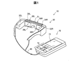
図1は、本発明の一実施形態としての頭部装着型表示装置10の構成を示す説明図である。頭部装着型表示装置10は、頭部に装着する表示装置であり、ヘッドマウントディスプレイ(Head Mounted Display、HMD)とも呼ばれる。このHMD10は、片側の手の機能回復訓練(リハビリ)を行うためのものである。HMD10は、本実施形態では、使用者が、虚像を視認すると同時に現実空間も視認可能な光学透過型(シースルー型)である。
Next, an embodiment of the present invention will be described.
A. Basic configuration of HMD:
FIG. 1 is an explanatory diagram showing a configuration of a head-mounted
HMD10は、眼鏡のような形状を有する表示装置20と、制御装置(コントローラー)70とを備える。表示装置20と制御装置70との間は、有線または無線で、通信可能に接続される。本実施形態では、表示装置20と制御装置70とが、有線のケーブル90で接続されている。制御装置70は、表示装置20との間で、ケーブル90を介して、画像の信号(画像信号)や制御の信号(制御信号)を通信する。
The HMD 10 includes a
表示装置20は、左眼用の表示部(左眼用表示部)30Lと、右眼用の表示部(右眼用表示部)30Rとを備える。
The
左眼用表示部30Lは、左眼用の画像形成部(左眼用画像形成部)32Lと、左眼用の導光部(図2に示される左眼用導光部34L)と、左眼用の反射部(左眼用反射部)36Lと、左眼用シェード38Lとを備える。右眼用表示部30Rは、右眼用の画像形成部(右眼用画像形成部)32Rと、右眼用の導光部(図2に示される左眼用導光部34Lと同様なもの)と、右眼用の反射部(右眼用反射部)36Rと、右眼用シェード38Rとを備える。
The left-
図2は、左眼用表示部30Lの構成を詳細に示す説明図である。図2は、左眼用表示部30Lを真上から見た図である。左眼用表示部30Lに備えられる左眼用画像形成部32Lは、メガネのテンプル(つる)の根元部分に配置され、左眼用の画像生成部(左眼用画像生成部)321Lと、左眼用の投射光学系(左眼用投射光学系)322Lとを備える。
FIG. 2 is an explanatory diagram showing the configuration of the left-
左眼用画像生成部321Lは、左眼用のバックライトの光源(左眼用バックライト光源)BLと、左眼用の光変調素子(左眼用光変調素子)LMとを備える。バックライト光源BLは、本実施形態では、赤色、緑色および青色といった発光色ごとの光源の集合から構成されている。各光源としては、例えば、発光ダイオード(LED)などを用いることができる。光変調素子LMは、本実施形態では、表示素子である液晶表示デバイスによって構成されている。
The left-eye
左眼用表示部30Lは、次のように作用する。左眼用画像生成部321Lに、制御装置70(図1)から左眼用の画像信号が入力されると、左眼用バックライト光源BLの各光源が、赤色光、緑色光および青色光を射出する。各光源から射出された赤色光、緑色光および青色光は拡散して、左眼用光変調素子LMに投射される。左眼用光変調素子LMは、制御装置70から左眼用画像生成部321Lに入力された画像信号に応じて、投射された赤色光、緑色光および青色光を空間変調することにより、画像信号に応じた画像光を射出する。
The left-
左眼用投射光学系322Lは、例えば、投射レンズ群から構成され、左眼用画像生成部321Lの左眼用光変調素子LMから射出された画像光を投射して、平行な状態の光束にする。左眼用投射光学系322Lにより平行な状態の光束にされた画像光は、左眼用導光部34Lに投射される。
The left-eye projection
左眼用導光部34Lは、左眼用投射光学系322Lからの画像光を、左眼用反射部36Lが有する三角プリズムの予め定められた面(半透過反射面)に導く。左眼用反射部36Lに形成されている半透過反射面の表裏のうち、装着時に使用者の左眼EYに向く側には、ミラー層などの反射コーティングが施されている。左眼用反射部36Lに形成されている半透過反射面に導かれた画像光は、この反射コーティングされた面により、使用者の左眼EYに向けて全反射される。これにより、左眼用反射部36Lの予め定められた位置のエリア(画像取り出しエリア)から、前記導かれた画像光に応じた画像光が出力される。出力された画像光は使用者の左眼EYに入って、その左眼EYの網膜上に画像(虚像)を形成する。
The left-eye
左眼用反射部36Lに現実空間から入射する光の少なくとも一部は、左眼用反射部36Lに形成されている前述した半透過反射面を透過し、使用者の左眼EYに導かれる。これにより、使用者には、左眼用画像形成部32Lにより形成された画像と、現実空間からの光学像とが重畳されて見える。
At least a part of the light incident on the left-
左眼用シェード38Lは、左眼用導光部34Lの使用者の左眼EYとは反対の側に配置され、本実施形態では、取り外し可能である。左眼用シェード38Lは、明るい場所や画面に集中したい時に取り付けられることで、左眼用画像形成部32Lにより形成された画像を、使用者は明瞭に見ることができる。
The left-
図1に示すように、右眼用表示部30Rは、上記構成の左眼用表示部30Lと左右対称の同様な構成を有しており、左眼用表示部30Lと同様に作用する。この結果、使用者は、表示装置20を頭部に装着することにより、表示装置20の画像取り出しエリア(左眼用反射部36Lの画像取り出しエリア、右眼用反射部36Rの画像取り出しエリア)から出力される画像光に応じた画像が表示されているように見えることで、その画像を認識することができる。また、使用者は、表示装置20の画像取り出しエリア(左眼用反射部36Lの画像取り出しエリア、右眼用反射部36Rの画像取り出しエリア)に現実空間からの光の少なくとも一部が透過させられることにより、表示装置20を頭部に装着したまま、現実空間を見ることができる。
As shown in FIG. 1, the right-
このように、使用者は、表示装置20の画像取り出しエリアに表示された画像(以下、単に「表示画像」と呼ぶ)と、透過してきた現実空間とを同時に見る(視認する)ことができる。表示画像が、使用者に拡張現実感(AR:Augmented Reality)を与えるAR画像となる。 As described above, the user can simultaneously view (view) the image displayed in the image extraction area of the display device 20 (hereinafter simply referred to as “display image”) and the transmitted real space. The displayed image is an AR image that gives the user augmented reality (AR).
表示装置20において、使用者が表示装置20を装着した際の使用者の眉間に対応する位置には、カメラ51が設けられている。そのため、使用者が表示装置20を頭部に装着した状態において、カメラ51は、使用者が向いている方向の現実空間を撮像する。カメラ51は、単眼カメラであるが、ステレオカメラであってもよい。
In the
制御装置70は、表示装置20を制御するための装置である。制御装置70は、タッチパッド72と、操作ボタン部74とを備える。タッチパッド72は、タッチパッド72の操作面上での接触操作を検出して、検出内容に応じた信号を出力する。タッチパッド72としては、静電式や圧力検出式、光学式といった種々のタッチパッドを採用することができる。操作ボタン部74は、種々の操作ボタンを有し、各操作ボタンの操作を検出して、検出内容に応じた信号を出力する。タッチパッド72および操作ボタン部74は、使用者によって操作される。
The
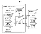
図3は、HMD10の構成を機能的に示すブロック図である。制御装置70は、CPU80と、記憶部82と、運動モデルデータベース84と、入力情報取得部86と、電源部88とを備え、各部はバス等により相互に接続されている。
FIG. 3 is a block diagram functionally showing the configuration of the
記憶部82は、ROM、RAM、DRAM、ハードディスク等によって構成される。記憶部82には、オペレーティングシステム(ОS)をはじめとする種々のコンピュータープログラムが格納されている。本実施形態では、格納されているコンピュータープログラムの一つとしてリハビリ用プログラムがある。
The
運動モデルデータベース84は、運動モデルを蓄積したデータベースである。運動モデルは、リハビリの際に目標とされる運動をモデル化した動画データであり、本実施形態では、左手の運動モデルと、右手の運動モデルが予め蓄積されている。なお、運動モデルは、動画データに換えて、いくつかの静止画データの集まりとしてもよい。さらには、運動モデルは、手の特徴点位置の集合から構成されるデータであってもよく、動画を構築し得るデータであればいずれのデータに換えることもできる。さらに、運動モデルは、運動の回数や速度などのパラメータを含むようにしてもよい。
The
入力情報取得部86は、前述したタッチパッド72および操作ボタン部74を含む。入力情報取得部86は、タッチパッド72や操作ボタン部74からの検出内容に応じた信号を入力する。
The input
電源部88は、制御装置70および表示装置20に備えられた電源を必要とする各構成部に、電源を供給する。
The
CPU80は、記憶部82に格納されているコンピュータープログラムを読み出して実行することにより、各種の機能を奏する。具体的には、CPU80は、入力情報取得部86から操作の検出内容の入力があった場合に当該検出結果に応じた処理を実行する機能、記憶部82に対してデータの読み書きを行う機能、および電源部88から各構成部への電源の供給を制御する機能を奏する。
The
また、CPU80は、記憶部82に格納されているリハビリ用プログラムを読み出して実行することにより、リハビリ処理を実行するリハビリ処理部82aとしても機能する。リハビリ処理は、障害のある身体部分(ここでは、片側の手)の正常動作を表すAR画像を表示することによって、HMD10の使用者に協調運動訓練を行わせためものである。CPU80と、CPU80によって実行される機能としてのリハビリ処理部82aとが、「表示制御部」の下位概念に相当する。
The
B.準備作業について:
本実施形態では、リハビリの対象者、すなわち、HMD10の使用者として、片手に障害が残り、片手は健常である患者を想定している。障害としては、例えば、脳卒中による麻痺がある。以下、障害のある手を「障害手」、障害のない手を「健常手」と呼ぶ。なお、「健常である」とは、一切、障害がない状態に限る必要はなく、機能的に多少の障害がある場合であってもよい。
B. About preparatory work:
In this embodiment, as a rehabilitation subject, that is, a user of the
使用者は、HMD10を使用して協調運動訓練を行うに際し、2つの準備作業を行う必要がある。第1番目の準備作業は、マーカーを貼り付ける作業である。マーカーは、HMD10においてAR画像を表示する位置を指定するための標識である。
The user needs to perform two preparatory tasks when performing the coordinated exercise training using the
図4は、マーカーの貼り付け位置を示す説明図である。図4(a)は健常手の手のひらの側を示し、図4(b)は健常手の甲の側を示す。ここでは、右手が健常手であるものとする。マーカーは4つ用意されている。図4(a)に示すように、健常手NHの手のひらの側に、3つのマーカーM1,M2,M3が貼り付けられる。詳しくは、第1のマーカーM1は手のひらの親指の付け根(いわゆる金星丘)に、第2のマーカーM2は手のひらの中指の先端に、第3のマーカーM3は手のひらの小指の下の手首よりのふくらみ(いわゆる火星丘)に、それぞれ貼り付けられる。 FIG. 4 is an explanatory diagram showing a marker attachment position. 4 (a) shows the palm side of a healthy hand, and FIG. 4 (b) shows the back side of a healthy hand. Here, it is assumed that the right hand is a healthy hand. Four markers are prepared. As shown in FIG. 4A, three markers M1, M2, and M3 are attached to the palm side of the healthy hand NH. Specifically, the first marker M1 is at the base of the thumb of the palm (so-called Venus Hill), the second marker M2 is at the tip of the middle finger of the palm, and the third marker M3 is a bulge from the wrist under the little finger of the palm. (So-called Martian hill) is affixed to each.
なお、これらマーカーMK1〜MK3の貼付位置は、健常手NHの外縁を規定するに適した位置であり、上記の例に限る必要はない。例えば、第1のマーカーM1は手のひらの親指の先端位置に、第3のマーカーM3は手のひらの小指の先端位置に換えることもできる。また、マーカーの数も、3つに限る必要はなく、例えば、第1〜第3のマーカーM1〜M3に親指の先端位置、人差し指の先端位置、薬指の先端位置を加えた合計7つとした構成、親指の先端位置と手のひらの小指の先端位置とに貼り付ける合計2つとした構成等、種々の数とすることができる。 In addition, the sticking positions of these markers MK1 to MK3 are positions suitable for defining the outer edge of the healthy hand NH, and need not be limited to the above example. For example, the first marker M1 can be replaced with the tip position of the palm thumb, and the third marker M3 can be replaced with the tip position of the little finger of the palm. Also, the number of markers need not be limited to three. For example, a total of seven markers is provided by adding the tip position of the thumb, the tip position of the index finger, and the tip position of the ring finger to the first to third markers M1 to M3. Various configurations such as a total of two configurations that are attached to the tip position of the thumb and the tip position of the little finger of the palm can be used.
図4(b)に示すように、健常手NHの手の甲の側の親指と人差し指の間に、第4のマーカーM4が貼り付けられる。第4のマーカーMK4の貼付位置は、これに限る必要はなく、後述する協調運動訓練の初期構えにおいて健常手を認識可能な位置であれば、いずれの位置とすることもできる。また、健常手NHの手の甲の側のマーカーは、1つに限る必要もなく、複数とすることもできる。 As shown in FIG. 4B, a fourth marker M4 is pasted between the thumb and the index finger on the back side of the hand of the healthy hand NH. The attachment position of the fourth marker MK4 is not limited to this, and any position can be used as long as it can recognize a healthy hand in the initial posture of the cooperative exercise training described later. Further, the number of markers on the back side of the hand of the healthy hand NH is not limited to one, and may be plural.
各マーカーM1〜M4の貼り付けは、リハビリの補助者によって行われる。なお、使用者が、障害のある側である左手でマーカーM1〜M4の貼り付けを行うことができれば、使用者自身で貼り付けるようにしてもよい。 The markers M1 to M4 are attached by a rehabilitation assistant. Note that if the user can paste the markers M1 to M4 with the left hand on the handicapped side, the user may paste the markers themselves.
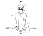
図5は、第2番目の準備作業の様子を示す説明図である。第1番目の準備作業が済むと、使用者は、第2番目の準備作業として、HMD10の表示装置20を頭部に装着した状態で、机やテーブル等のリハビリ台TBの前に位置する。そして、使用者HUは、障害手FHである左手と、健常手NHである右手とをリハビリ台TBの上に差し出す。健常手NHは、手のひらを上側に向け、手を広げた状態とする。「手を広げた状態」とは、各指の関節は伸ばされ、各指の間は広げられた状態であり、いわゆるパーの状態である。健常手NHには、第1番目の準備作業によって、マーカーM1〜M4が貼り付けられている。障害手FHは、手のひらを上側に向け、自然な状態、すなわち、各指の関節が若干、曲げられた状態とする。本実施形態では、リハビリ台TBの上には、リハビリ用の小道具として、把持物体、例えば名刺BCが置かれている。
FIG. 5 is an explanatory diagram showing the state of the second preparatory work. When the first preparation work is completed, the user is positioned in front of the rehabilitation table TB such as a desk or table with the
図5の状態で、HMD10の制御装置70のタッチパッド72や操作ボタン部74(図1)が操作されることで、HMD10に対してリハビリ処理の実行が指示される。この操作は、例えば、リハビリの補助者によってなされる。なお、使用者が健常手を用いて上記の操作を行い、その後、直ちに健常手を図5の状態としてもよい。
In the state of FIG. 5, when the
C.リハビリ処理:
図6および図7は、制御装置70によって実行されるリハビリ処理を示すフローチャートである。このリハビリ処理は、リハビリ処理部82a(図3)の処理であり、入力情報取得部86(図3)によってリハビリ処理の実行の指示を受け付けたときに、CPU80によって、実行開始される。
C. Rehabilitation processing:
6 and 7 are flowcharts showing the rehabilitation process executed by the
図6に示すように、処理が開始されると、CPU80は、まず、カメラ51によって撮影を行い(ステップS110)、その撮影によって得られた撮影画像の中に、手のひらの側に貼り付けたマーカーM1〜M3が含まれるか否かを判定する(ステップS120)。ここでは、マーカーM1〜M3が含まれるとは、3つのマーカーM1〜M3の全てが含まれることをいい、マーカーM1〜M3のうちの一つでも含まれない場合には、マーカーM1〜M3が含まれないと判定される。
As shown in FIG. 6, when the processing is started, the
使用者は、図5の状態において、リハビリを行うに際し、手のあるリハビリ台TBに視線を移す。カメラ51は、使用者の向いている方向の現実空間を撮像することになることから、リハビリ台TBに視線を移したときに、カメラ51による撮影画像の中にマーカーM1〜M3が含まれることになり、ステップS120において肯定判定される。肯定判定された場合には、CPU80は、ステップS130に処理を進める。一方、ステップS120でマーカーM1〜M3が含まれないと判定された場合には、CPU80は、ステップS110に処理を戻して、ステップS110からステップS120までの処理を繰り返し実行する。
In performing the rehabilitation in the state of FIG. 5, the user moves his / her line of sight to the rehabilitation table TB with a hand. Since the
ステップS130では、CPU80は、ステップS110によって得られた撮影画像の中から各マーカーM1〜M3を検出し、各マーカーM1〜M3の二次元位置座標を求める。二次元位置座標を示す座標系は、表示装置20による表示画面に対応したものである。3つのマーカーM1〜M3は、健常手NHの外縁を規定していることから、これらのマーカーM1〜M3の二次元位置座標の広がりは、使用者の手の(実際の)大きさと、マーカーからカメラ51までの距離とによって定まる。マーカーからカメラ51までの距離は、三つのマーカーM1〜M3のうちのいずれか一つのマーカーの撮影画像における大きさに基づいて求めることができる。このため、続くステップS140では、CPU80は、ステップS130で求めた各マーカーM1〜M3の二次元位置座標と、一つのマーカーの撮影画像における大きさとに基づいて、使用者の手の(実際の)大きさを認定する。
In step S130, the
次いで、CPU80は、ステップS130で求めた各マーカーM1〜M3の二次元位置座標から、マーカーM1〜M3が貼り付けられた健常手NHが右手か左手かを判定する(ステップS150)。各マーカーM1〜M4は個別に識別可能であることから、手のひらの親指の付け根に設けられた第1のマーカーM1が、手のひらの小指の下の手首よりに設けられた第3のマーカーM3に対して右側に位置するか左側に位置するかによって、健常手NHが右手か左手かを判定することができる。なお、この判定の方法は、一例であり、各マーカーM1〜M3の配置されている位置関係から判定する方法であれば、いずれの方法によってもよい。
Next, the
続いて、CPU80は、ステップS150で判定された手の側と反対の側を障害手と認識し、その障害手の側に対応した運動モデルを、運動モデルデータベース84から読み出す(ステップS160)。すなわち、ステップS150で健常手が右手と判定されたときには、障害手は左手であるから左手の運動モデルを読み出し、一方、ステップS150で健常手が左手と判定されたときには、障害手は右手であるから右手の運動モデルを読み出す。運動モデルの詳細については、後述する。
Subsequently, the
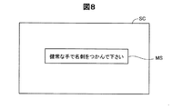
図6のステップS160の実行後、CPU80は、図7のステップS170に処理を進める。ステップS170では、CPU80は、使用者にリハビリの初期構えを取ることを促すためのメッセージを、HMD10の表示装置10に表示させる。ここでは、「初期構え」は、健常手NHで名刺BCを把持する格好である。
After execution of step S160 in FIG. 6, the
図8は、ステップS170で表示されるメッセージの一例を示す説明図である。図中のSCは、表示装置10による表示画面である。ステップS110では、具体的には、例えば「健常な側の手で名刺をつかんで下さい」とのメッセージMSが表示画面SCに表示される。このメッセージMSを表示画面SCから視認した使用者は、健常手NHで名刺BC(図5)をつかむ(把持する)動作を行う。
FIG. 8 is an explanatory diagram illustrating an example of the message displayed in step S170. SC in the figure is a display screen by the
図9は、健常手NHで名刺BCをつかんだ状態で使用者によって視認される表示画面SCを示す説明図である。図示するように、使用者は、表示画面SC内に、透過してきた現実空間の実像として、名刺BCを掴んだ状態の健常手NHと、障害手FHとを視認する。 FIG. 9 is an explanatory diagram showing a display screen SC that is visually recognized by the user while holding the business card BC with the healthy hand NH. As shown in the drawing, the user visually recognizes the healthy hand NH holding the business card BC and the hand FH as a real image of the transmitted real space in the display screen SC.
ステップS170(図7)の実行後、CPU80は、カメラ51によって撮影を行い(ステップS180)、その撮影によって得られた撮影画像の中に、手の甲の側に貼り付けた第4のマーカーM4が含まれるか否かを判定する(ステップS190)。第4のマーカーM4は、健常手NHにおける手の甲の側の親指と人差し指の間に貼り付けられていることから、健常手NHで名刺BCをつかんだときに、カメラ51による撮影画像の中に第4のマーカーM4が含まれることになり、ステップS190において肯定判定される。肯定判定された場合には、CPU80は、ステップS200に処理を進める。一方、ステップS190で第4のマーカーM4が含まれないと判定された場合には、CPU80は、ステップS180に処理を戻して、ステップS180からステップS190までの処理を繰り返し実行する。
After execution of step S170 (FIG. 7), the
ステップS200では、CPU80は、ステップS180によって得られた撮影画像の中から第4のマーカーM4を検出し、第4のマーカーM4の二次元位置座標を求める。二次元位置座標を示す座標系は、表示装置20による表示画面に対応したものである。
In step S200, the
続いて、CPU80は、ステップS200で求めた第4のマーカーM4の二次元位置座標と、第4のマーカーM4の撮影画像における大きさと、把持物体である名刺の(実際の)大きさとに基づいて、障害手の位置を推定する(ステップS210)。「障害手の位置」とは、本実施形態では、右手と左手を使って名刺BCを把持するという協調運動を行う際に障害手(例えば左手)がとり得る位置である。第4のマーカーM4の二次元位置座標は健常手NH(例えば右手)の位置を定めることから、この第4のマーカーM4の二次元位置座標から名刺の撮影画像における大きさ分だけ離れた位置に、障害手があることが判る。名刺の撮影画像における大きさは、名刺の(実際の)大きさと、マーカーからカメラ51までの距離とに基づいて求めることができる。このため、第4のマーカーM4の二次元位置座標と、第4のマーカーM4の撮影画像における大きさと、名刺の(実際の)大きさとに対して、協調運動の際に視認される障害手の位置が一義的に定まる。
Subsequently, the
本実施形態では、第4のマーカーM4の二次元位置座標を変数Xとし、第4のマーカーM4の撮影画像における大きさを変数Yとし、名刺の(実際の)大きさを定数Cとし、協調運動の際に視認される障害手の位置を変数Zとし、変数X、Yおよび定数Cに対する変数Zを表す数式を、実験的にあるいはシミュレーションによって求め、記憶部に82に予め記憶しておく。ステップS210では、この数式を用いることで、協調運動の際に表示装置20において視認される障害手の位置を求める。名刺の(実際の)大きさが、「参照情報」の下位概念に相当する。
In this embodiment, the two-dimensional position coordinate of the fourth marker M4 is a variable X, the size of the fourth marker M4 in the captured image is a variable Y, and the (actual) size of the business card is a constant C. The position of the hand that is visually recognized during the exercise is defined as a variable Z, and mathematical expressions representing the variable Z with respect to the variables X and Y and the constant C are obtained experimentally or by simulation, and stored in the
ステップS210(図7)の実行後、CPU80は、ステップS140によって認識された使用者の手の大きさに基づいて、ステップS160によって読み出された運動モデルの大きさを調整する(ステップS220)。
After execution of step S210 (FIG. 7), the
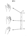
図10は、ステップS160によって読み出された運動モデルの一例を示す説明図である。図示した運動モデルMDは、左手の運動モデルである。運動モデルMDは、複数のフレーム(静止画)FR1,…,FR2,…,FR3によって構成される動画データである。FR1〜FR3のそれぞれの間にも、1または複数のフレームが含まれる。 FIG. 10 is an explanatory diagram illustrating an example of the exercise model read out in step S160. The illustrated motion model MD is a left hand motion model. The motion model MD is moving image data composed of a plurality of frames (still images) FR1, ..., FR2, ..., FR3. One or more frames are also included between each of FR1 to FR3.
最初のフレームFR1は、手のひらを上側に向け、自然な状態を表す。この状態は、図5の障害手FHの状態とほぼ一致している。最後のフレームFR3は、把持物体である名刺BC(図5)をつかんだときの手の状態を表す。最初のフレームFR1と最後のフレームFR3との中間のフレームFR2は、上記の手のひらを上側に向けた自然な状態から名刺をつかんだときの状態までの中間の状態を表す。 The first frame FR1 represents a natural state with the palm facing upward. This state substantially coincides with the state of the hand FH in FIG. The last frame FR3 represents the state of the hand when holding the business card BC (FIG. 5), which is a gripping object. An intermediate frame FR2 between the first frame FR1 and the last frame FR3 represents an intermediate state from the natural state in which the palm is directed upward to the state when the business card is grasped.
上述したように構成された運動モデルMDによれば、手のひらを上側に向けた自然な状態から名刺をつかんだときの状態までの連続した運動、すなわち、名刺を把持する際の運動が示されることになる。ステップS220では、この運動モデルMDの大きさを、ステップS140によって認識された使用者の手の大きさに基づいて調整する。すなわち、運動モデルデータベース84(図3)に記憶されている運動モデルは、成人の一般的な大きさであることから、ステップS220では、その運動モデルを、使用者の手の大きさに合致するように、拡大または縮小するサイズ調整を行う。 According to the motion model MD configured as described above, continuous motion from the natural state with the palm facing upward to the state when the business card is grasped, that is, motion when gripping the business card is shown. become. In step S220, the size of the motion model MD is adjusted based on the size of the user's hand recognized in step S140. That is, since the exercise model stored in the exercise model database 84 (FIG. 3) is a general size of an adult, in step S220, the exercise model matches the size of the user's hand. In this way, the size is adjusted to be enlarged or reduced.
その後、CPU80は、ステップS210によって推定された障害手の位置で、ステップS220によってサイズ調整された運動モデルを再生(表示)する(ステップS230)。この表示は、先に説明した左眼用表示部30Lおよび右眼用表示部30Rを動作させることによって行われる。
Thereafter, the
図11は、再生時において使用者によって視認される画像の一例を示す説明図である。図中の実線で示した左手の画像が、再生した運動モデルの画像(AR画像)Gaである。図中の破線で示した右手、左手の画像が、透過して見える現実空間に実在する使用者の健常手NHと障害手FHである。図示するように、使用者にとって、障害手FHに対して運動モデルの画像Gaが重畳されて視認される。図示の例では、運動モデルの画像Gaは、名刺BCをつかんだ状態であり、図10の最後のフレームFR3の画像である。使用者は、手を広げた状態から、運動モデルの画像Gaの動きに追従して手を開閉することで、協調運動訓練を行う。 FIG. 11 is an explanatory diagram illustrating an example of an image visually recognized by the user during reproduction. The left-hand image shown by the solid line in the figure is the reproduced motion model image (AR image) Ga. The right hand and left hand images shown by broken lines in the figure are the user's healthy hand NH and handicapped hand FH that are actually present in the real space. As shown in the figure, the image Ga of the motion model is superimposed on the hand FH and visually recognized by the user. In the illustrated example, the image Ga of the motion model is a state in which the business card BC is grasped, and is the image of the last frame FR3 in FIG. The user performs cooperative exercise training by opening and closing the hand following the movement of the image Ga of the exercise model from the state where the hand is spread out.
図7のステップS230の実行後、CPU80は、リハビリを継続するか否かを判定する(ステップS240)。制御装置70のタッチパッド72や操作ボタン部74(図1)が操作されることで、HMD10に対してリハビリを継続する旨が指示される。CPU80は、入力情報取得部86(図2)によって、リハビリを継続する旨の指示を受け付けたときに、リハビリを継続すると判定する。上記のタッチパッド72や操作ボタン部74の操作は、例えば、リハビリの補助者によってなされる。なお、使用者が健常手を用いて上記の操作を行い、その後、直ちに健常手を図5の状態に戻すようにしてもよい。
After execution of step S230 in FIG. 7, the
ステップS240で、リハビリを継続すると判定された場合には、CPU80は、ステップS170に処理を戻して、ステップS170からステップS240までの処理を繰り返し実行する。一方、ステップS240で、リハビリを継続しないと判定された場合に、このリハビリ処理のルーチンを終了する。
When it is determined in step S240 that the rehabilitation is continued, the
D.実施形態の効果:
以上のように構成された実施形態のHMD10によれば、障害手FHの正常動作を表すAR画像の表示位置が、健常手NHに取り付けられたマーカーM1〜M4の位置から決定される。このために、本実施形態では、障害のある身体部分にマーカーを取り付ける必要がない。したがって、マーカーM1〜M4の取り付けに困ることを解消できると共に、マーカーM1〜M4によってリハビリ運動がスムーズに行われなくなることを防止できる。
D. Effects of the embodiment:
According to the
また、使用者は、先に説明したように(図11参照)、障害手FHに運動モデルの画像Gaを重ね合わせて視認することができることから、運動モデルの画像Gaが自分の手であると錯覚して協調運動訓練を行うことができる。したがって、本実施形態のリハビリ装置100によれば、錯覚効果によって、手の麻痺を改善させる効果を高めることができる。 In addition, as described above (see FIG. 11), the user can visually recognize the exercise model image Ga by superimposing the exercise model image Ga on the hand FH, so that the exercise model image Ga is his / her hand. The illusion can be used for coordinated exercise training. Therefore, according to the rehabilitation device 100 of the present embodiment, the effect of improving hand paralysis can be enhanced by the illusion effect.
E.変形例:
この発明は前記実施形態やその変形例に限られるものではなく、その要旨を逸脱しない範囲において種々の態様において実施することが可能であり、例えば、次のような変形も可能である。
E. Variations:
The present invention is not limited to the above-described embodiment and its modifications, and can be carried out in various modes without departing from the gist thereof. For example, the following modifications are possible.
・変形例1:
前記実施形態では、協調運動は、右手と左手を使って把持物体を把持する動作であった。これに対して、変形例として、協調運動は、右手と左手を使って太鼓を叩く動作、右手と左手を組む動作、右手と左手を使ってキーボードを打つ動作等としてもよい。また、協調運動は、右手と左手を使う動作に限る必要はなく、右腕と左腕、右足と左足(足首からつま先まで)、右脚と左脚(足首から骨盤まで)等としてもよい。また、一対の身体部分は、左右対称となっている同じ機能を有する身体部分としたが、これに限る必要もなく、右手と左腕、右手と左足、右手の左脚等としてもよい。これら協調運動では、一対の身体部分のうちの一方の身体部分の位置が決まれば、他方の身体部分の位置が推定できることから、前記実施形態と同様な作用効果を奏することができる。
・ Modification 1:
In the embodiment, the cooperative motion is an operation of gripping the gripped object using the right hand and the left hand. On the other hand, as a modification, the cooperative movement may be an operation of hitting the drum using the right hand and the left hand, an operation of combining the right hand and the left hand, an operation of hitting the keyboard using the right hand and the left hand, and the like. Further, the coordinated movement is not limited to the operation using the right hand and the left hand, and may be a right arm and a left arm, a right foot and a left foot (from an ankle to a toe), a right leg and a left leg (from an ankle to a pelvis), and the like. Moreover, although a pair of body part was made into the body part which has the same function which is left-right symmetric, it is not necessary to restrict to this, It is good also as a right hand and a left arm, a right hand and a left foot, a right leg, etc. In these coordinated movements, if the position of one body part of a pair of body parts is determined, the position of the other body part can be estimated, and therefore the same effects as those of the above embodiment can be achieved.
・変形例2:
前記実施形態では、協調運動に用いる把持物体は、名刺としたが、これに換えて、物差し、トレイ等の他の形状の物体としてもよい。また、用いる道具は、把持物体に限る必要もなく、つかんだ状態で保持するもの等、種々の状態で保持するものに換えることもできる。また、協調運動は、道具を用いないものとしてもよい。なお、協調運動が道具を用いたものである場合には、この道具の大きさが参照情報として記憶される。
Modification 2
In the above embodiment, the gripping object used for the cooperative movement is a business card, but instead, it may be an object of another shape such as a ruler or a tray. Further, the tool to be used is not limited to the gripping object, and can be changed to ones that are held in various states, such as those that are held in a gripped state. Further, the coordinated movement may not use a tool. Note that when the coordinated movement uses a tool, the size of the tool is stored as reference information.
・変形例3:
前記実施形態では、手のひらの側に3つのマーカーを貼り付けて、これらマーカーから使用者の手の大きさを認識し、この手の大きさに基づいて運動モデルの大きさを調整するようにしていた。これに対して、変形例として、手のひらの側にマーカーを貼り付けることをやめて、運動モデルの大きさの調整を行わない構成としてもよい。すなわち、手の甲の側につけた第4のマーカーM4だけを用いて、AR画像の表示位置を決めるようにしてもよい。
・ Modification 3:
In the above embodiment, three markers are attached to the palm side, the size of the user's hand is recognized from these markers, and the size of the motion model is adjusted based on the size of the hand. It was. On the other hand, as a modification, it may be configured such that the marker is not pasted on the palm side and the size of the motion model is not adjusted. That is, the display position of the AR image may be determined using only the fourth marker M4 attached to the back of the hand.
・変形例4:
前記実施形態では、HMDは、装着した状態で使用者の視界が遮断されない透過型の表示装置とした。これに対して、変形例として、HMDは、使用者の視界が遮断される非透過型の表示装置としてもよい。非透過型のHMDは、現実空間の画像をカメラによって撮影し、この撮影された画像にAR画像を重畳させるものである。また、HMDは、左眼用表示部と右眼用表示部とを備える構成としたが、これに換えて、片眼用の表示部だけを備える構成としてもよい。
-Modification 4:
In the above embodiment, the HMD is a transmissive display device that does not block the user's view when worn. On the other hand, as a modification, the HMD may be a non-transmissive display device that blocks the user's field of view. The non-transmissive HMD captures a real space image with a camera and superimposes an AR image on the captured image. Moreover, although HMD was set as the structure provided with the display part for left eyes, and the display part for right eyes, it is good also as a structure provided only with the display part for one eye instead.
・変形例5:
前記各実施形態および変形例では、AR画像を表示し得る表示装置として、使用者の頭部に装着される頭部装着型表示装置を用いたが、表示装置はこれに限られず、種々変形可能である。例えば、使用者の肩や首に装着したアームによって支持される表示装置のように、頭部や肩、首等の使用者の身体に装着される身体装着型表示装置を用いてもよい。また、使用者に装着されるのではなく、テーブル等に載置される載置型の表示装置であってもよい。
-Modification 5:
In each of the above-described embodiments and modifications, a head-mounted display device mounted on the user's head is used as a display device that can display an AR image. However, the display device is not limited to this and can be variously modified. It is. For example, a body-mounted display device attached to the user's body such as the head, shoulder, or neck may be used like a display device supported by an arm attached to the user's shoulder or neck. Further, the display device may be a mounting type display device that is not mounted on the user but mounted on a table or the like.
・変形例6:
前記各実施形態および変形例では、リハビリ処理部82a(図3)は、CPU80が記憶部82に格納されているコンピュータープログラムを実行することにより実現されるものとして記載した。しかし、これらリハビリ処理部は、当該機能を実現するために設計されたASIC(Application Specific Integrated Circuit:特定用途向け集積回路)を用いて構成されてもよい。
Modification 6:
In each of the above-described embodiments and modifications, the
・変形例7:
前記各実施形態および変形例では、表示装置20にカメラ51が一体的に取り付けられている構成として記載したが、表示装置20とカメラ51とが別体として設けられる構成としてもよい。
Modification 7:
In each of the embodiments and the modifications described above, the
本発明は、上述の実施形態や実施例、変形例に限られるものではなく、その趣旨を逸脱しない範囲において種々の構成で実現できる。例えば、発明の概要の欄に記載した各形態中の技術的特徴に対応する実施形態、実施例、変形例中の技術的特徴は、上述の課題の一部または全部を解決するために、あるいは、上述の効果の一部または全部を達成するために、適宜、差し替えや組み合わせを行うことが可能である。また、その技術的特徴が本明細書中に必須なものとして説明されていなければ、適宜、削除することが可能である。 The present invention is not limited to the above-described embodiments, examples, and modifications, and can be realized with various configurations without departing from the spirit of the present invention. For example, the technical features in the embodiments, examples, and modifications corresponding to the technical features in each embodiment described in the summary section of the invention are to solve some or all of the above-described problems, or In order to achieve part or all of the above-described effects, replacement or combination can be performed as appropriate. Further, if the technical feature is not described as essential in the present specification, it can be deleted as appropriate.
10…頭部装着型表示装置(HMD)
20…表示装置
30L…左眼用表示部
30R…右眼用表示部
32L…左眼用画像形成部
32R…右眼用画像形成部)
34L…左眼用導光部
36L…左眼用反射部
36R…右眼用反射部
38L…左眼用シェード
38R…右眼用シェード
51…カメラ
70…制御装置
72…タッチパッド
74…操作ボタン部
80…CPU
82…記憶部
82a…リハビリ処理部
84…運動モデルデータベース
86…入力情報取得部
88…電源部
90…ケーブル
321L…左眼用画像生成部
322L…左眼用投射光学系
BL…左眼用バックライト光源
LM…左眼用光変調素子
BC…名刺
HU…使用者
NH…健常手
FH…障害手
SC…表示画面
TB…リハビリ台
M1〜M4…マーカー
MD…運動モデル
Ga…AR画像
10 ... Head-mounted display device (HMD)
20 ...
34L: Light guide for
DESCRIPTION OF
Claims (5)
前記一対の身体部分のうちの健常である身体部分に取り付けられたマーカーを撮影し得る撮影部と、
前記一対の身体部分のうちの障害のある身体部分の正常動作を表す画像を、前記表示部に表示させる表示制御部と、
を備え、
前記表示制御部は、
前記撮影されたマーカーの位置に基づいて、前記障害のある身体部分についての、前記協調運動の際に前記表示部において視認される位置を推定し、
前記推定された位置に、前記画像を表示させる、
表示装置。 A display unit capable of visually recognizing a pair of body parts performing coordinated movement;
An imaging unit capable of imaging a marker attached to a healthy body part of the pair of body parts;
A display control unit that causes the display unit to display an image representing a normal operation of a disabled body part of the pair of body parts;
With
The display control unit
Based on the position of the photographed marker, the position that is visually recognized on the display unit during the coordinated movement of the body part with the obstacle is estimated,
Displaying the image at the estimated position;
Display device.
前記表示制御部は、
前記協調運動の際の前記健常である身体部分に対する前記障害のある身体部分の相対位置を特定しうる参照情報を予め記憶し、
前記視認される位置の推定を、前記撮影されたマーカーの位置と前記参照情報とに基づいて行う、表示装置。 The display device according to claim 1,
The display control unit
Pre-stores reference information that can identify the relative position of the disabled body part with respect to the healthy body part during the coordinated movement;
A display device that estimates the visually recognized position based on the position of the photographed marker and the reference information.
前記一対の身体部分は、両手であり、
前記協調運動は、把持物体を前記両手で把持する運動であり、
前記参照情報は、前記把持物体の大きさである、表示装置。 The display device according to claim 2,
The pair of body parts is both hands,
The coordinated motion is a motion of gripping a gripped object with both hands,
The display device, wherein the reference information is a size of the gripped object.
前記表示部は、頭部装着型の表示部である、表示装置。 A display device according to any one of claims 1 to 3,
The display unit is a display device that is a head-mounted display unit.
前記一対の身体部分のうちの障害のある身体部分の正常動作を表す画像を、前記表示部に表示させる機能を、コンピューターに実現させ、
前記機能は、
前記撮影部によって撮影されたマーカーの位置に基づいて、前記障害のある身体部分についての、前記協調運動の際に前記表示部において視認される位置を推定し、
前記推定された位置に、前記画像を表示させる、
コンピュータープログラム。 To control a display device comprising: a display unit capable of visually recognizing a pair of body parts performing coordinated movement; and a photographing unit capable of photographing a marker attached to a healthy body part of the pair of body parts. Computer program
The computer realizes a function of causing the display unit to display an image representing a normal operation of a disabled body part of the pair of body parts,
The function is
Based on the position of the marker imaged by the imaging unit, the position that is visually recognized on the display unit during the cooperative movement for the disabled body part is estimated,
Displaying the image at the estimated position;
Computer program.
Priority Applications (3)
| Application Number | Priority Date | Filing Date | Title |
|---|---|---|---|
| JP2015141083A JP2017018519A (en) | 2015-07-15 | 2015-07-15 | Display device and computer program |
| US15/196,452 US20170014683A1 (en) | 2015-07-15 | 2016-06-29 | Display device and computer program |
| CN201610550815.6A CN106344333A (en) | 2015-07-15 | 2016-07-13 | Display device |
Applications Claiming Priority (1)
| Application Number | Priority Date | Filing Date | Title |
|---|---|---|---|
| JP2015141083A JP2017018519A (en) | 2015-07-15 | 2015-07-15 | Display device and computer program |
Publications (1)
| Publication Number | Publication Date |
|---|---|
| JP2017018519A true JP2017018519A (en) | 2017-01-26 |
Family
ID=57775589
Family Applications (1)
| Application Number | Title | Priority Date | Filing Date |
|---|---|---|---|
| JP2015141083A Pending JP2017018519A (en) | 2015-07-15 | 2015-07-15 | Display device and computer program |
Country Status (3)
| Country | Link |
|---|---|
| US (1) | US20170014683A1 (en) |
| JP (1) | JP2017018519A (en) |
| CN (1) | CN106344333A (en) |
Cited By (2)
| Publication number | Priority date | Publication date | Assignee | Title |
|---|---|---|---|---|
| JP2019054988A (en) * | 2017-09-21 | 2019-04-11 | 恭太 青木 | Motor coordination evaluation method and program |
| JP2021003379A (en) * | 2019-06-26 | 2021-01-14 | 学校法人北里研究所 | Rehabilitation support device and program |
Families Citing this family (9)
| Publication number | Priority date | Publication date | Assignee | Title |
|---|---|---|---|---|
| JP6897177B2 (en) * | 2017-03-10 | 2021-06-30 | セイコーエプソン株式会社 | Computer programs for training equipment that can be used for rehabilitation and training equipment that can be used for rehabilitation |
| US11275453B1 (en) | 2019-09-30 | 2022-03-15 | Snap Inc. | Smart ring for manipulating virtual objects displayed by a wearable device |
| US11798429B1 (en) | 2020-05-04 | 2023-10-24 | Snap Inc. | Virtual tutorials for musical instruments with finger tracking in augmented reality |
| US11520399B2 (en) | 2020-05-26 | 2022-12-06 | Snap Inc. | Interactive augmented reality experiences using positional tracking |
| US11925863B2 (en) * | 2020-09-18 | 2024-03-12 | Snap Inc. | Tracking hand gestures for interactive game control in augmented reality |
| US11546505B2 (en) | 2020-09-28 | 2023-01-03 | Snap Inc. | Touchless photo capture in response to detected hand gestures |
| US11740313B2 (en) | 2020-12-30 | 2023-08-29 | Snap Inc. | Augmented reality precision tracking and display |
| US11531402B1 (en) | 2021-02-25 | 2022-12-20 | Snap Inc. | Bimanual gestures for controlling virtual and graphical elements |
| EP4327185A1 (en) | 2021-04-19 | 2024-02-28 | Snap, Inc. | Hand gestures for animating and controlling virtual and graphical elements |
Family Cites Families (3)
| Publication number | Priority date | Publication date | Assignee | Title |
|---|---|---|---|---|
| WO2006086504A2 (en) * | 2005-02-09 | 2006-08-17 | Alfred E. Mann Institute For Biomedical Engineering At The University Of Southern California | Method and system for training adaptive control of limb movement |
| JP2012501020A (en) * | 2008-08-25 | 2012-01-12 | ウニヴェルジテート チューリッヒ プロレクトラート エムエヌヴェー | Adjustable virtual reality system |
| CA2933053A1 (en) * | 2013-12-20 | 2015-06-25 | Integrum Ab | System for neuromuscular rehabilitation |
-
2015
- 2015-07-15 JP JP2015141083A patent/JP2017018519A/en active Pending
-
2016
- 2016-06-29 US US15/196,452 patent/US20170014683A1/en not_active Abandoned
- 2016-07-13 CN CN201610550815.6A patent/CN106344333A/en active Pending
Cited By (3)
| Publication number | Priority date | Publication date | Assignee | Title |
|---|---|---|---|---|
| JP2019054988A (en) * | 2017-09-21 | 2019-04-11 | 恭太 青木 | Motor coordination evaluation method and program |
| JP2021003379A (en) * | 2019-06-26 | 2021-01-14 | 学校法人北里研究所 | Rehabilitation support device and program |
| JP7262763B2 (en) | 2019-06-26 | 2023-04-24 | 学校法人北里研究所 | Rehabilitation support device and program |
Also Published As
| Publication number | Publication date |
|---|---|
| CN106344333A (en) | 2017-01-25 |
| US20170014683A1 (en) | 2017-01-19 |
Similar Documents
| Publication | Publication Date | Title |
|---|---|---|
| JP2017018519A (en) | Display device and computer program | |
| US10712901B2 (en) | Gesture-based content sharing in artificial reality environments | |
| JP6393367B2 (en) | Tracking display system, tracking display program, tracking display method, wearable device using them, tracking display program for wearable device, and operation method of wearable device | |
| JP6870264B2 (en) | Exercise training equipment and programs | |
| CN112567287A (en) | Augmented reality display with frame modulation | |
| JP2017012264A (en) | Rehabilitation assist implement and rehabilitation apparatus | |
| WO2014128747A1 (en) | I/o device, i/o program, and i/o method | |
| JP6250024B2 (en) | Calibration apparatus, calibration program, and calibration method | |
| JP2010102215A (en) | Display device, image processing method and computer program | |
| CN108428375A (en) | A kind of teaching auxiliary and equipment based on augmented reality | |
| JP2017067876A (en) | Head-mounted display, method for controlling head-mounted display, and computer program | |
| US20240077937A1 (en) | Devices, methods, and graphical user interfaces for controlling avatars within three-dimensional environments | |
| CN113138664A (en) | Eyeball tracking system and method based on light field perception | |
| JP2018183272A (en) | Training device, training system, program, and control device | |
| JP6394108B2 (en) | Head-mounted display device, control method therefor, and computer program | |
| US20240103616A1 (en) | User interfaces for gaze tracking enrollment | |
| US20240118746A1 (en) | User interfaces for gaze tracking enrollment | |
| US20230384860A1 (en) | Devices, methods, and graphical user interfaces for generating and displaying a representation of a user | |
| US20240103678A1 (en) | Devices, methods, and graphical user interfaces for interacting with extended reality experiences | |
| US20240029377A1 (en) | Devices, Methods, and Graphical User Interfaces for Providing Inputs in Three-Dimensional Environments | |
| US20240103636A1 (en) | Methods for manipulating a virtual object | |
| JP2019005243A (en) | Training device, training system, program, and control device | |
| WO2024036364A1 (en) | Augmented reality systems, devices and methods | |
| KR20230157156A (en) | Method and apparatus for estimating the distance to the hand of ar glasses device | |
| WO2023195995A1 (en) | Systems and methods for performing a motor skills neurological test using augmented or virtual reality |