JP2017017993A - Vehicle and control method - Google Patents
Vehicle and control method Download PDFInfo
- Publication number
- JP2017017993A JP2017017993A JP2016189617A JP2016189617A JP2017017993A JP 2017017993 A JP2017017993 A JP 2017017993A JP 2016189617 A JP2016189617 A JP 2016189617A JP 2016189617 A JP2016189617 A JP 2016189617A JP 2017017993 A JP2017017993 A JP 2017017993A
- Authority
- JP
- Japan
- Prior art keywords
- power
- vehicle
- discharge
- secondary battery
- amount
- Prior art date
- Legal status (The legal status is an assumption and is not a legal conclusion. Google has not performed a legal analysis and makes no representation as to the accuracy of the status listed.)
- Pending
Links
Images
Classifications
-
- Y—GENERAL TAGGING OF NEW TECHNOLOGICAL DEVELOPMENTS; GENERAL TAGGING OF CROSS-SECTIONAL TECHNOLOGIES SPANNING OVER SEVERAL SECTIONS OF THE IPC; TECHNICAL SUBJECTS COVERED BY FORMER USPC CROSS-REFERENCE ART COLLECTIONS [XRACs] AND DIGESTS
- Y02—TECHNOLOGIES OR APPLICATIONS FOR MITIGATION OR ADAPTATION AGAINST CLIMATE CHANGE
- Y02E—REDUCTION OF GREENHOUSE GAS [GHG] EMISSIONS, RELATED TO ENERGY GENERATION, TRANSMISSION OR DISTRIBUTION
- Y02E60/00—Enabling technologies; Technologies with a potential or indirect contribution to GHG emissions mitigation
- Y02E60/10—Energy storage using batteries
-
- Y—GENERAL TAGGING OF NEW TECHNOLOGICAL DEVELOPMENTS; GENERAL TAGGING OF CROSS-SECTIONAL TECHNOLOGIES SPANNING OVER SEVERAL SECTIONS OF THE IPC; TECHNICAL SUBJECTS COVERED BY FORMER USPC CROSS-REFERENCE ART COLLECTIONS [XRACs] AND DIGESTS
- Y02—TECHNOLOGIES OR APPLICATIONS FOR MITIGATION OR ADAPTATION AGAINST CLIMATE CHANGE
- Y02T—CLIMATE CHANGE MITIGATION TECHNOLOGIES RELATED TO TRANSPORTATION
- Y02T10/00—Road transport of goods or passengers
- Y02T10/60—Other road transportation technologies with climate change mitigation effect
- Y02T10/70—Energy storage systems for electromobility, e.g. batteries
-
- Y—GENERAL TAGGING OF NEW TECHNOLOGICAL DEVELOPMENTS; GENERAL TAGGING OF CROSS-SECTIONAL TECHNOLOGIES SPANNING OVER SEVERAL SECTIONS OF THE IPC; TECHNICAL SUBJECTS COVERED BY FORMER USPC CROSS-REFERENCE ART COLLECTIONS [XRACs] AND DIGESTS
- Y02—TECHNOLOGIES OR APPLICATIONS FOR MITIGATION OR ADAPTATION AGAINST CLIMATE CHANGE
- Y02T—CLIMATE CHANGE MITIGATION TECHNOLOGIES RELATED TO TRANSPORTATION
- Y02T10/00—Road transport of goods or passengers
- Y02T10/60—Other road transportation technologies with climate change mitigation effect
- Y02T10/72—Electric energy management in electromobility
-
- Y—GENERAL TAGGING OF NEW TECHNOLOGICAL DEVELOPMENTS; GENERAL TAGGING OF CROSS-SECTIONAL TECHNOLOGIES SPANNING OVER SEVERAL SECTIONS OF THE IPC; TECHNICAL SUBJECTS COVERED BY FORMER USPC CROSS-REFERENCE ART COLLECTIONS [XRACs] AND DIGESTS
- Y02—TECHNOLOGIES OR APPLICATIONS FOR MITIGATION OR ADAPTATION AGAINST CLIMATE CHANGE
- Y02T—CLIMATE CHANGE MITIGATION TECHNOLOGIES RELATED TO TRANSPORTATION
- Y02T90/00—Enabling technologies or technologies with a potential or indirect contribution to GHG emissions mitigation
- Y02T90/10—Technologies relating to charging of electric vehicles
- Y02T90/16—Information or communication technologies improving the operation of electric vehicles
- Y02T90/167—Systems integrating technologies related to power network operation and communication or information technologies for supporting the interoperability of electric or hybrid vehicles, i.e. smartgrids as interface for battery charging of electric vehicles [EV] or hybrid vehicles [HEV]
-
- Y—GENERAL TAGGING OF NEW TECHNOLOGICAL DEVELOPMENTS; GENERAL TAGGING OF CROSS-SECTIONAL TECHNOLOGIES SPANNING OVER SEVERAL SECTIONS OF THE IPC; TECHNICAL SUBJECTS COVERED BY FORMER USPC CROSS-REFERENCE ART COLLECTIONS [XRACs] AND DIGESTS
- Y04—INFORMATION OR COMMUNICATION TECHNOLOGIES HAVING AN IMPACT ON OTHER TECHNOLOGY AREAS
- Y04S—SYSTEMS INTEGRATING TECHNOLOGIES RELATED TO POWER NETWORK OPERATION, COMMUNICATION OR INFORMATION TECHNOLOGIES FOR IMPROVING THE ELECTRICAL POWER GENERATION, TRANSMISSION, DISTRIBUTION, MANAGEMENT OR USAGE, i.e. SMART GRIDS
- Y04S10/00—Systems supporting electrical power generation, transmission or distribution
- Y04S10/12—Monitoring or controlling equipment for energy generation units, e.g. distributed energy generation [DER] or load-side generation
- Y04S10/126—Monitoring or controlling equipment for energy generation units, e.g. distributed energy generation [DER] or load-side generation the energy generation units being or involving electric vehicles [EV] or hybrid vehicles [HEV], i.e. power aggregation of EV or HEV, vehicle to grid arrangements [V2G]
-
- Y—GENERAL TAGGING OF NEW TECHNOLOGICAL DEVELOPMENTS; GENERAL TAGGING OF CROSS-SECTIONAL TECHNOLOGIES SPANNING OVER SEVERAL SECTIONS OF THE IPC; TECHNICAL SUBJECTS COVERED BY FORMER USPC CROSS-REFERENCE ART COLLECTIONS [XRACs] AND DIGESTS
- Y04—INFORMATION OR COMMUNICATION TECHNOLOGIES HAVING AN IMPACT ON OTHER TECHNOLOGY AREAS
- Y04S—SYSTEMS INTEGRATING TECHNOLOGIES RELATED TO POWER NETWORK OPERATION, COMMUNICATION OR INFORMATION TECHNOLOGIES FOR IMPROVING THE ELECTRICAL POWER GENERATION, TRANSMISSION, DISTRIBUTION, MANAGEMENT OR USAGE, i.e. SMART GRIDS
- Y04S30/00—Systems supporting specific end-user applications in the sector of transportation
- Y04S30/10—Systems supporting the interoperability of electric or hybrid vehicles
- Y04S30/14—Details associated with the interoperability, e.g. vehicle recognition, authentication, identification or billing
-
- Y—GENERAL TAGGING OF NEW TECHNOLOGICAL DEVELOPMENTS; GENERAL TAGGING OF CROSS-SECTIONAL TECHNOLOGIES SPANNING OVER SEVERAL SECTIONS OF THE IPC; TECHNICAL SUBJECTS COVERED BY FORMER USPC CROSS-REFERENCE ART COLLECTIONS [XRACs] AND DIGESTS
- Y04—INFORMATION OR COMMUNICATION TECHNOLOGIES HAVING AN IMPACT ON OTHER TECHNOLOGY AREAS
- Y04S—SYSTEMS INTEGRATING TECHNOLOGIES RELATED TO POWER NETWORK OPERATION, COMMUNICATION OR INFORMATION TECHNOLOGIES FOR IMPROVING THE ELECTRICAL POWER GENERATION, TRANSMISSION, DISTRIBUTION, MANAGEMENT OR USAGE, i.e. SMART GRIDS
- Y04S50/00—Market activities related to the operation of systems integrating technologies related to power network operation or related to communication or information technologies
- Y04S50/12—Billing, invoicing, buying or selling transactions or other related activities, e.g. cost or usage evaluation
Landscapes
- Charge And Discharge Circuits For Batteries Or The Like (AREA)
- Electric Propulsion And Braking For Vehicles (AREA)
- Secondary Cells (AREA)
- Supply And Distribution Of Alternating Current (AREA)
- Current-Collector Devices For Electrically Propelled Vehicles (AREA)
- Management, Administration, Business Operations System, And Electronic Commerce (AREA)
- Remote Monitoring And Control Of Power-Distribution Networks (AREA)
- Financial Or Insurance-Related Operations Such As Payment And Settlement (AREA)
Abstract
Description
本発明は、二次電池に充電されている電力を利用する車両、制御方法に関する。 The present invention relates to a vehicle that uses power charged in a secondary battery, and a control method.
近年、二次電池に充電された電力を用いて走行する車両が増えている。そして特許文献1には、電気自動車のバッテリ(二次電池)を充電する際やバッテリを放電させて宅内に給電する際に電力を効率的に利用できるシステムが開示されている。 In recent years, an increasing number of vehicles travel using electric power charged in secondary batteries. Patent Document 1 discloses a system that can efficiently use electric power when charging a battery (secondary battery) of an electric vehicle or discharging the battery to supply power to the house.
ここで、上述のような車両に備わる二次電池に充電された電力は主に車両の走行用に利用されるが、電力を対価として支払う取引が新たに求められてきつつある社会情勢の中で、当該二次電池に充電された電力を利用した店舗における売買の決済をすることのできる技術が求められている。 Here, the electric power charged in the secondary battery provided in the vehicle as described above is mainly used for driving the vehicle, but in a social situation where a transaction for paying electric power as a consideration is newly demanded. Therefore, there is a demand for a technology that can make a settlement of purchases and purchases in a store using the power charged in the secondary battery.
そこでこの発明は、車両に備わる二次電池に充電された電力により店舗における売買の決済をすることのできる車両、制御方法を提供することを目的としている。 In view of this, an object of the present invention is to provide a vehicle and a control method capable of making a settlement of purchases and purchases in a store using electric power charged in a secondary battery provided in the vehicle.
発明の第1の態様によれば、車両は、車両の駐車時に、地上側の電力の充放電機構と相対する位置に具備され、搭載している二次電池に充電されている電力を、無線エネルギーにより非接触で地上側へ出力するとともに、地上側から電力が無線エネルギーにより非接触で入力される充放電機構と、前記二次電池から地上側へ出力される電力を制御する電力放出制御装置と、前記電力放出制御装置と電力を金額情報へ変換する外部システムと通信を行う車載器と、を備え、前記電力放出制御装置は、前記車載器からの指示に基づいて前記充放電機構を制御し、前記車両に搭載された二次電池に充電されている電力であって、無線エネルギーにより非接触で、購入対象の対価として用いる電力を、地上側の前記外部システム側へ供給する。 According to the first aspect of the invention, when the vehicle is parked, the vehicle is wirelessly supplied with the electric power charged in the mounted secondary battery that is provided at a position opposite to the charge / discharge mechanism of electric power on the ground side. A charging / discharging mechanism that outputs power to the ground side in a non-contact manner by energy, and power that is input from the ground side in a contactless manner by wireless energy, and a power discharge control device that controls power output from the secondary battery to the ground side And an on-vehicle device that communicates with the power emission control device and an external system that converts power into monetary information, and the power emission control device controls the charge / discharge mechanism based on an instruction from the on-vehicle device. Then, the electric power charged in the secondary battery mounted on the vehicle is supplied to the external system side on the ground side in a non-contact manner by wireless energy and used as the consideration for the purchase target.
上述の車両において、前記車載器は、電力放出の開始の指示と、充電量下限制限値との入力を受け付けて、それら電力放出の開始の指示と前記充電量下限制限値とを前記電力放出制御装置へ出力する電力放出処理部を備え、前記電力放出制御装置は、前記電力放出の開始の指示を受け付けた場合、前記充電量下限制限値と現在の充電量とを比較して、現在の充電量が前記充電量下限制限値の示す値より大きい場合に前記充放電機構を制御して前記車両に搭載された二次電池に充電されている電力を前記外部システム側へ供給する。 In the vehicle described above, the vehicle-mounted device receives an instruction to start power discharge and a charge amount lower limit value and inputs the power discharge start instruction and the charge amount lower limit value to the power discharge control. A power discharge processing unit that outputs to the device, and the power discharge control device compares the charge amount lower limit value with the current charge amount when receiving an instruction to start the power discharge, When the amount is larger than the value indicated by the charge amount lower limit value, the charge / discharge mechanism is controlled to supply the power charged in the secondary battery mounted on the vehicle to the external system side.
上述の車両において、前記電力放出制御装置は、前記充放電機構を制御して前記車両に搭載された二次電池に充電されている電力を放電している際に、当該二次電池の充電量が前記充電量下限制限値に所定の充電量を加えた値に達した場合に放電停止と判定する。 In the vehicle described above, when the power discharge control device controls the charge / discharge mechanism to discharge the power charged in the secondary battery mounted on the vehicle, the charge amount of the secondary battery Is determined to stop discharging when the value reaches a value obtained by adding a predetermined charge amount to the charge amount lower limit value.
上述の車両において、前記電力放出処理部は、車両のユーザの識別情報に対応付けて前記外部システムが記憶している情報であって、過去に前記車両に搭載された前記二次電池から放電され前記外部システムの二次電池に充電された電力量のうち商品の決済に利用しなかった未使用電力の電力量を示す情報を、前記外部システムが金額情報に変換した後に取得し、前記金額情報をディスプレイに表示する。 In the vehicle described above, the power release processing unit is information stored in the external system in association with identification information of a user of the vehicle, and is discharged from the secondary battery previously mounted on the vehicle. Obtaining information indicating the amount of unused electric power that was not used for product payment out of the amount of power charged in the secondary battery of the external system after the external system converted into amount information, the amount information Appears on the display.
上述の車両において、前記電力放出処理部は、前記車両に搭載された二次電池に充電されている電力の放電を停止した後、放電電力量を前記外部システムへ送信する。 In the vehicle described above, the power release processing unit stops discharging the power charged in the secondary battery mounted on the vehicle, and then transmits the amount of discharged power to the external system.
上述の車両において、前記電力放出処理部は、入力を受け付けた車両の識別情報であって前記充放電機構の位置の特定に用いる識別情報を含む放電準備開始信号を前記外部システムへ出力することを特徴とする。 In the vehicle described above, the power release processing unit outputs a discharge preparation start signal including identification information used to identify the position of the charge / discharge mechanism, which is identification information of the vehicle that has received an input, to the external system. Features.
発明の第2の態様によれば、制御方法は、車両の駐車時に、地上側の電力の充放電機構と相対する位置に具備され、搭載している二次電池に充電されている電力を、無線エネルギーにより非接触で地上側へ出力するとともに、地上側から電力が無線エネルギーにより非接触で入力される充放電機構と、前記二次電池から地上側へ出力される電力を制御する電力放出制御装置と、を備えた車両の制御方法であって、前記車両の車載器が、電力放出操作の入力に基づいて前記電力放出制御装置と電力を金額情報へ変換する外部システムと通信を行い、前記車両の電力放出制御装置が、前記車載器からの指示に基づいて前記充放電機構を制御し、前記車両に搭載された二次電池に充電されている電力であって、無線エネルギーにより非接触で、購入対象の対価として用いる電力を、地上側の前記外部システム側へ供給する。 According to the second aspect of the invention, when the vehicle is parked, the control method includes the power charged in the mounted secondary battery, which is provided at a position opposite to the ground-side power charging / discharging mechanism. A charge / discharge mechanism that outputs power to the ground without contact by wireless energy, and power that is input from the ground without contact by wireless energy, and power discharge control that controls power output from the secondary battery to the ground An on-vehicle device of the vehicle communicates with the power release control device and an external system that converts power into money amount information based on an input of a power release operation, A vehicle power release control device controls the charge / discharge mechanism based on an instruction from the vehicle-mounted device, is a power charged in a secondary battery mounted on the vehicle, and is contactless by wireless energy. , Purchase The power used in exchange for elephants, and supplies the ground side to the external system side.
本発明によれば、車両に備わる二次電池に充電された電力を金額情報へと換算して、店舗における決済処理において有効に利用することができる。 ADVANTAGE OF THE INVENTION According to this invention, the electric power charged in the secondary battery with which a vehicle is provided can be converted into money amount information, and can be used effectively in the payment process in a store.
以下、図面に基づいて本発明の実施形態につき説明する。
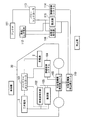
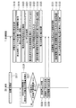
図1は、本発明にかかる充放電可能な車両の構成を示す機能ブロック図である。
通常のバッテリ車の場合は、パワーコントローラ113の制御信号に基づき、系統(または二次電池)112から、高周波発生器116を経由して地上側コイル110に電力が供給される。そして、電磁誘導作用により、車両側コイル105に誘導電力が発生し、整流器103を経て整流された電力が二次電池3に充電される。なお、無線制御システム104、無線制御システム114は、パワーコントローラ113からの指令に基づき、二次電池3への充電作業時に必要となる制御信号を、車両側と地上側との間で送受信する車両側の無線制御システム、および地上側の無線制御システムである。
Hereinafter, an embodiment of the present invention will be described with reference to the drawings.
FIG. 1 is a functional block diagram showing a configuration of a chargeable / dischargeable vehicle according to the present invention.
In the case of a normal battery car, electric power is supplied from the system (or secondary battery) 112 to the
本発明にかかる充放電可能な車両20には、車両20側からの放電に必要となる高周波発生器102が車両20内に装備されている。そして、地上側には充電に必要となる整流器115が備えられている。
すなわち、車両20側からの放電時には、バッテリコントローラ101の制御信号に基づき、二次電池3から、高周波発生器102を経由して車両側コイル105に電力が供給される。そして、電磁誘導作用により、地上側コイル110に誘導電力が発生し、整流器115を経て整流された電力が地上側の内部二次電池202(例えば図1の二次電池112に相当)に充電される(あるいは直接交流系統へ接続されてもよい)。
The chargeable /
That is, when discharging from the
図1では、車両側コイル105は、路面に配置された地上側コイル110と対面できるよう、車両20下部の路面と対向する位置に設置されているが、これに限定されるものではなく、車両20が駐停車されるエリア(例えば、駐車場)において、当該エリアに配置されている地上側コイル(充放電機構)110と相対する位置となるよう、車両20側に設置されるものであればよい。
なお、車載器106は地上側のアンテナ111とDSRC等による通信を行う機器である。
In FIG. 1, the vehicle-
The vehicle-mounted device 106 is a device that communicates with the ground-
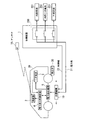
図2は、充放電可能な車両20を用いた電力利用システムの構成を示す機能ブロック図であり、車両20側から店舗側に電力を放電する場合における車両側と店舗側の機能を示したものである。
この図において、店舗装置(外部システム)1は、車両20に備わる電力放出機構5(図1の充放電機構105に相当)から非接触で無線エネルギーを入力して電力に変換し二次電池3に充電する装置である。また店舗装置1は、内部系統201(店舗内で使用している電力系統)、内部二次電池202(店舗が所有する二次電池)または外部系統203(店舗が電力の売買契約を行っている電力会社など)と電力線31とを切替て接続及び開閉する切替スイッチ200を備えている。充電機構10は、車両20の電力放出機構5から非接触で無線エネルギーを入力して電力に変換する装置である。なお、ここで店舗とは、コンビニやスーパー等を始めとする、消費者に対し物やサービスを提供するところを意味するものである。
FIG. 2 is a functional block diagram showing the configuration of a power usage system using the chargeable /
In this figure, a store apparatus (external system) 1 receives wireless energy from a power discharge mechanism 5 (corresponding to the charge /
また車両20は、車載器2、二次電池3、電力放出制御装置4、電力放出機構5を備えている。
車載器2は電力放出制御開始要求とユーザからの入力情報とに基づいて、電力放出制御の開始を電力放出制御装置4へ指示する装置であり、例えば、DSRC(Dedicated Short Range Communications)通信などの技術を用いて店舗装置1の備えるアンテナ18との間で情報を送受信する。
また二次電池3は車両20の電力源であり、車両20に備わる走行用モータやその他の各種装置に電力を供給するとともに、決済を行うために電力放出する電力を蓄積する。
また電力放出制御装置4は、二次電池3に蓄積されている電力を放出する電力放出機構5を制御する装置である。
また電力放出機構5は、二次電池3に蓄積されている電力を入力して無線エネルギーに変換し、充電機構10へ出力する装置である。
The
The vehicle-mounted
The
The power release control device 4 is a device that controls the
The
ここで車両20の電力放出機構5が、充電機構10に出力する無線エネルギーは、磁界、マイクロ波等である。例えば、電力放出機構5が二次電池3から得た電力を用いて磁界を発生し、充電機構10がその磁界を電磁誘導の技術により電力に変換する。
また充電機構10は、店舗などの駐車スペース等に設置されているが、当該駐車スペースには、車両20の電力放出機構5の位置が充電機構10の位置に対向するように車両20が停車できるようにするための車止め30が設けられている。充電機構10は駐車スペースの地上に、また、店舗装置1から制御によって車止め30に基づいて停車した車両20の前後方向の所定範囲内を移動可能に設置されている。なお充電機構10は、車止め30に基づいて停車した車両20の左右方向等の他の方向の所定範囲内にも移動可能に設置されてよい。
Here, the wireless energy output from the
The
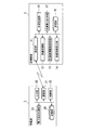
図3は電力利用システムにおける車載器と店舗装置の構成を示す機能ブロック図である。
この図が示すように、店舗装置1は、通信部11、準備処理部12、充電機構駆動制御部13、金額情報算出部14、決済処理部15、充電電力計測部17、の各処理部と、記憶部16とを備えている。
ここで通信部11は、アンテナ18を介して車載器2と通信する処理部である。
また準備処理部12は、車両20から電力放出を行うための準備処理等を行う処理部である。
また充電機構駆動制御部13は、無線エネルギーに基づく電力を所定の充電効率閾値以上で(無線エネルギーの所定の入力効率以上で)車両20から充電できる位置に充電機構10を移動させる処理部である。
また金額情報算出部14は、電力放出機構5から非接触で無線エネルギーを入力した電力の電力量に基づいて金額情報を算出する処理部である。
また決済処理部15は、金額情報算出部14の算出した金額情報を用いて決済処理を行う処理部である。
また充電電力計測部17は、充電機構10が無線エネルギーを入力して変換し二次電池202に蓄積した電力量を計測する処理部である。
また記憶部16は、処理に利用する各種情報を記憶する。
FIG. 3 is a functional block diagram illustrating configurations of the vehicle-mounted device and the store apparatus in the power usage system.
As shown in this figure, the store apparatus 1 includes a
Here, the
In addition, the
In addition, the charging mechanism drive control unit 13 is a processing unit that moves the
The monetary
The
The charging power measuring unit 17 is a processing unit that measures the amount of power that the
The
また車載器2は、入力部26、通信部21、制御部22、電力放出処理部23の各処理部と、記憶部24を備えている。
入力部26は、タッチパネルに表示される操作画面などのユーザインタフェースによるユーザ操作の情報を入力する処理部である。
また通信部21は、車載器2のアンテナを介して店舗装置1と情報を送受信する処理部である。
また制御部22は各種処理の制御を行なう処理部である。
また電力放出処理部23は、電力放出のための各種処理を行う処理部である。
また記憶部24は、処理に利用する各種情報を記憶する。
なお、車載器2は車両20に搭載されるカーナビゲーション装置やオーディオ装置等の装置に内蔵されてよい。
The vehicle-mounted
The
The communication unit 21 is a processing unit that transmits / receives information to / from the store apparatus 1 via the antenna of the vehicle-mounted
The control unit 22 is a processing unit that controls various processes.
The power
The
The vehicle-mounted
上述した各処理部や記憶部の構成により、車両の二次電池3に充電された電力を店舗装置1において有効利用することのできる電力利用システムを提供する。
With the configuration of each processing unit and storage unit described above, a power usage system is provided that can effectively use the power charged in the
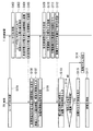
図4は図1の電力利用システムの処理フローを示す第1の図である。
図5は図1の電力利用システムの処理フローを示す第2の図である。
次に、電力利用システムの処理フローについて順を追って説明する。
まず、車両20を運転するユーザ(消費者)は、店舗装置1を備えた店舗でサービスを受けるために、当該店舗の停車スペースまで車両20を運転し、車両20を所定の位置に停車させる。この時、車止め30に車両20のタイヤを合わせることにより、充電機構10の近傍に、車両20に備わる電力放出機構5が対向して位置することができるように充電機構10の位置や、電力放出機構5の車両20における取り付け位置が予め設定されているものとする。なお店舗の停車スペースとは、具体的にはドライブスルーで商品を販売できる店舗の車両20の走行帯の一角でもよいし、店舗の前に設けられている駐車場のスペースであってもよい。
FIG. 4 is a first diagram showing a processing flow of the power usage system of FIG.
FIG. 5 is a second diagram showing a processing flow of the power usage system of FIG.
Next, the processing flow of the power usage system will be described in order.
First, the user (consumer) who drives the
ここでユーザは、店舗における商品の購入金額の一部または全部の決済を、車両20の二次電池3に既に充電されている電力を用いて行うことができる。ユーザは購入金額の一部または全部の決済を、車両20の二次電池3に既に充電されている電力等を用いて行う場合、車載器2を操作して、電力放出のための操作を行う。この時ユーザは車載器2へユーザIDを入力する。ユーザIDは、入力部26が入力して電力放出処理部23へ出力する。電力放出処理部23はユーザIDを入力すると、当該ユーザIDを、通信部21を介して店舗装置1へ送信する(ステップS101)。ユーザIDの信号は、車載器2のアンテナから店舗装置1のアンテナ18へDSRC通信により送信される。
Here, the user can make a part or all of the purchase price of the product at the store using the power already charged in the
次に店舗装置1においては、通信部11がユーザIDを受信し(ステップS102)、当該信号に含まれるユーザIDを準備処理部12が取得する。準備処理部12は取得したユーザIDを現在処理中の車両20のユーザについての識別情報として記憶部16に記録する。ここで記憶部16は、過去に車両20の二次電池3から放電され、店舗装置1側に充電された電力量のうち、ユーザが商品の決済に利用しなかった未使用電力の電力量をユーザIDに対応付けて記憶部16に記録しており、準備処理部12は、記憶部16にユーザIDに対応付けられて記録されている電力量を抽出する(ステップS103)。また準備処理部12は、未使用電力の電力量を記憶部16が保持している所定の換算式(単位電力あたりの単価)を用いて金額情報に変換する(ステップS104)。そして、準備処理部12は、未使用電力の電力量と、その電力量を金額に換算した金額情報とを、通信部11を介して車載器2へ送信する(ステップS105)。
Next, in the store apparatus 1, the
車載器2の通信部21は、未使用電力の電力量と金額情報とを受信すると、電力放出処理部23へ出力する。すると電力放出処理部23は、図示されていないディスプレイ等(車両に装備されているカーナビ画面等)に未使用電力の電力量と金額情報とを表示する(ステップS106)。ユーザがディスプレイ等に表示された未使用電力の電力量と金額情報とを確認し、電力による決済あるいは店舗側への預電力を選択した場合には、入力部26は、ユーザの操作により停車スペース識別情報(停車スペース番号など)、車両20の車種を入力する(ステップS107)。そして電力放出処理部23は、停車スペース識別情報と、車種とを含む放電準備開始信号を、通信部21を介して店舗装置1へ送信する(ステップS108)。そして、店舗装置1の通信部11は放電準備開始信号を受信する(ステップS109)。
When the communication unit 21 of the vehicle-mounted
次に、店舗装置1の準備処理部12が、放電準備開始信号に含まれる停車スペース識別情報と、車種とを取得する。すると準備処理部12は、二次電池202と、充電機構10とを電力線31で接続する切替スイッチ200を閉に制御して、充電機構10と二次電池202とを接続する(ステップS110)。また準備処理部12は、充電機構駆動制御部13へ、停車スペース識別情報と車種とを出力する。充電機構駆動制御部13は、停車スペース識別情報と車種とを用いて、車両20が停車している停車スペースを特定するとともに、その車種で特定できる位置であって、二次電池3に充電されている電力を車両20から充電できる位置に、充電機構10を相対的に移動させる位置調整の制御を行う(ステップS111)。
Next, the
当該位置調整の制御の具体例としては、例えば、車両20側に電力放出機構5の設置位置を示すマーキング等を設けておき、充電機構10側に当該マーキング等の位置を検知するセンサ等を設けておく。そして、充電機構駆動制御部13の制御に基づいて、充電機構10が、当該マーキング等の位置情報を、制御線32を介して充電機構駆動制御部13へ送信する。そして、充電機構駆動制御部13は、受信したマーキング等の位置情報と、センサの等の位置との相対距離が近接する方向に充電機構10を移動させる制御を行う。
As a specific example of the position adjustment control, for example, a marking or the like indicating the installation position of the
または、他の位置調整の制御としては、予め車両20に備わる充電機構10の位置情報を、車両20の車種ごとに対応付けて記憶部16に記憶しておく。そして、充電機構駆動制御部13は、入力した車種に対応する充電機構10の位置情報を記憶部16から読み取り、その位置情報と、現在の充電機構10の位置情報とに基づいて、二次電池3に充電されている電力を車両20から充電できる位置に充電機構10を移動させる。
Alternatively, as another position adjustment control, the position information of the
そして充電機構駆動制御部13は位置調整が完了したと判定すると準備処理部12に位置調整完了を示す情報を出力する。すると準備処理部12は、準備完了を示す準備完了信号を、通信部11を介して車載器2へ送信する(ステップS112)。
When the charging mechanism drive control unit 13 determines that the position adjustment has been completed, the charging mechanism drive control unit 13 outputs information indicating the completion of the position adjustment to the
車載器2の電力放出処理部23は、通信部21を介して準備完了信号を入力する。すると電力放出処理部23は、ディスプレイ等へ準備完了を示す情報を表示する。ユーザはディスプレイ等に表示された準備完了を示す情報を確認すると、電力放出開始の指示(電力放出制御開始要求)と、充電量下降制限値を入力する(ステップS113)。充電量下降制限値は、例えば、これ以上の二次電池3の充電量の下降を禁止する二次電池3の充電量の下限値を示す。車両20の二次電池3に蓄電された電力は走行のためにも利用されるため、走行用に利用される電力量以上に放電されることを防ぐ必要がある。このため、ユーザは充電量下降制限値を入力する。電力放出処理部23は、電力放出開始の指示と、充電量下降制限値とを入力すると、電力放出制御装置4へ電力放出開始指示と充電量下降制限値とを出力する。なお、充電量下降制限値は予め定められた値であってもよい。
The power
次に電力放出制御装置4は、電力放出開始指示を入力すると、二次電池3から現在の充電力量を検出し、記憶部24に一時的に記録しておく。そして、電力放出制御装置4は、現在の充電量が、充電量下降制限値の示す充電量より大きいかを判定する(ステップS114)。電力放出制御装置4は、現在の充電量が、充電量下降制限値の示す充電量より大きい場合には、放電可能と判定し、電力放出機構5へ放電開始を指示するとともに、車載器2へ放電開始を通知する。車載器2は放電開始の通知を入力すると、ディスプレイ等に“放電中”を示す情報を表示するとともに(ステップS115)、車両20の電源やエンジンが始動できないよう当該車両20のシステム側に始動不可信号を出力する。他方、電力放出制御装置4は、現在の充電量が、充電量下降制限値の示す充電量より大きくない場合には、放電不可と判定し(ステップS116)、放電不可を示す情報を車載器2へ通知する。車載器2は放電不可を示す情報を入力した場合には、その情報をディスプレイ等に表示して処理を終了する。
Next, when the power discharge control device 4 inputs a power discharge start instruction, the power discharge control device 4 detects the current amount of charging power from the
電力放出機構5は、放電開始の指示を入力すると放電を開始する(ステップS117)。この時、電力放出機構5は二次電池3に蓄積された電力を入力し、当該電力を無線エネルギーに変換して充電機構10へ出力する。電力放出機構5は、電力放出制御装置4より放出停止の指示を入力するまで、電力を無線エネルギーに変換して充電機構10へ出力する。なお、電力放出機構5は、所定の電圧値、電流値で二次電池3より得た電力を無線エネルギーに変換して出力する。
The
充電機構10は、電力放出機構5が無線エネルギーにより電力を放出している間、その無線エネルギーを得て電力へ変換し、電力線31を介して二次電池202を充電する。この時、店舗装置1の充電電力計測部17は、二次電池202に充電された電力の電力量を計測する(ステップS118)。充電電力計測部17は、例えば、単位時間ごとに、当該単位時間あたりの充電電力量を計測して今回充電した総充電電力量を算出し、ユーザIDと対応付けて、都度、記憶部16に記録・更新する(ステップS119)。
The
以上のように、電力放出機構5からの電力放出は継続しているが、この電力放出の間に店舗装置1において車両20のユーザについての決済処理が発生する場合について以下に説明する。トリガーとして、店舗装置1と接続している当該店舗のレジシステム(図示せず)からの電力決済依頼(ユーザが店舗のレジで電力決済を選択した場合、レジ係の者がレジシステムに入力)に基づき、決済処理部15が電力決済処理の発生を検知する(ステップS120)。そして決済処理部15は、レジシステムに対しユーザIDの入力を要求し、レジでユーザにより入力されたユーザIDを取得する(ステップS121)。そして決済処理部15はユーザIDを金額情報算出部14に通知する。次に金額情報算出部14は、取得したユーザIDに対応付けられて記憶部16に記録されている最新の総充電電力量と過去の未使用電力の電力量とを読み取る。そして金額情報算出部14は、読み取った電力量の総和と所定の換算式とに基づき、電力決済が可能な金額情報を算出し、レジシステムに出力する(ステップS122)。レジシステムでユーザにより電力決済(通常のマネーによる決済を含む)が最終的に選択された場合は、決済処理部15は、当該レジシステムより、課金金額の情報を含む電力決済開始の指示を入力する(ステップS123)。すると決済処理部15は入力した課金金額の情報を所定の換算式に基づき電力量に変換する(ステップS124)。そして決済処理部15は課金金額の情報から換算された電力量を電力決済電力量として、記憶部16に出力して記録する(ステップS125)。
As described above, although the power release from the
電力放出制御装置4は、放電開始の指示を電力放出機構5へ出力した後は、所定の時間間隔で現在の二次電池3の充電量を検出する(ステップS126)。そして、電力放出制御装置4は、検出した二次電池3の充電量が、充電量下降制限値の示す充電量に、所定の僅かな充電量αを加算した充電量に達したかを判定する(ステップS127)。つまり、充電量下降制限値に近づいたかを判定している。そして、検出した二次電池3の充電量が、充電量下降制限値の示す充電量に、所定の僅かな充電量を加算した充電量に達した場合には、電力放出制御装置4は放電停止と判定し(ステップS128)、電力放出機構5による二次電池3に充電されている電力の出力を停止させる。電力放出制御装置4は、検出した二次電池3の充電量が、充電量下降制限値の示す充電量に、所定の僅かな充電量を加算した充電量に達していない場合には、放電制御を継続し、二次電池3の充電量の検出を繰り返す。そして、電力放出制御装置4は、放電停止と判定した場合、車載器2へ放電停止の情報を出力する。車載器2においては入力部26を介して電力放出処理部23が放電停止の情報を入力する。または、入力部26へユーザによる放電強制終了信号が入力される。放電停止または放電強制終了信号が入力されると、電力放出処理部23は、通信部21を介して放電終了を示す放電終了信号を送信する(ステップS129)。
After outputting the discharge start instruction to the
また電力放出制御装置4は、電力放出開始指示を入力した際に一時的に記憶部24に記録した二次電池3の充電量を読み取り、放電停止の情報または放電強制終了信号を車載器2から入力した際の二次電池3の充電量を読み取り、それら読み取った充電量の差を総放電電力量として算出する。そして、電力放出制御装置4は、総放電電力量を車載器2へ出力する。すると、車載器2の電力放出処理部23は、総放電電力量を通信部21を介して店舗装置1へ送信する(ステップS130)。
In addition, the power release control device 4 reads the charge amount of the
次に、店舗装置1においては、準備処理部12が放電終了信号を入力し、また充電電力計測部17が総放電電力量を入力する。準備処理部12は、放電終了信号を入力した場合、充電機構10とを電力線31で接続する切替スイッチ200を開に制御して、充電機構10と二次電池202との接続を遮断する(ステップS131)。また準備処理部12は充電機構10に放電終了を通知する。
Next, in the store apparatus 1, the
一方、充電電力計測部17は、総放電電力量を入力すると、既に充電電力計測部17が計測して都度、記憶部16に記録・更新した最新の総充電電力量を読み取る。そして、充電電力計測部17は、総放電電力量と総充電電力量とを比較して、大きい値を、今回の電力放出処理において放出された電力量であると判定し、その大きい電力量の値を、今回新たに充電された電力量として、ユーザIDに対応付けて記憶部16に記録する(ステップS132)。これにより、放電処理が完了する。また、決済処理部15が放電終了信号を入力し、記憶部16に記録されている、ユーザIDに対応した(A)未使用電力の電力量、(B)今回新たに充電された電力量、(C)電力決済電力量、に基づき、新たな未使用電力の電力量(=A+B−C)を算出し(ステップS133)、記憶部16に出力し記録する。なお、総放電電力量と総充電電力量のうちの大きい値を今回新たに充電された電力量としたが、小さい値、平均値、などを今回新たに充電された電力量としてもよい。
On the other hand, when the total discharge power amount is input, the charge power measurement unit 17 reads the latest total charge power amount that has already been measured by the charge power measurement unit 17 and recorded / updated in the
放電処理の終了後、店舗装置1において決済処理が発生する場合の決済処理は、レジシステムに出力される、電力決済が可能な金額情報が、「上記未使用電力の電力量A+最新の総充電電力量」に基づく金額ではなく、「上記未使用電力の電力量A+上記今回新たに充電完了となった電力量B」に基づく金額となる点を除き、電力放出の間に決済処理される場合と同様である。 After the end of the discharge process, the payment process in the case where the payment process occurs in the store apparatus 1 is the amount information that is output to the cash register system and that can be used for the power payment. When payment processing is performed during the release of power, except that the amount is based on “the amount of unused electric power A + the amount of electric power B that is newly charged this time” instead of the amount based on “the amount of power” It is the same.
なお本実施形態による店舗装置1は1つの店舗内に設置される装置として記載しているが、各処理部のうちのいずれか1つまたは複数の処理部が、異なる他の装置に含まれて構成され、それら複数の装置が通信ネットワークを介して接続されることにより連携して店舗装置1を構成してもよい。すなわち、店舗が全国に展開しているコンビニのような場合には、記憶部16をネットワークで共有しておくことで(ユーザIDに紐つく情報を共有しておくことで)、ユーザはどこのコンビニであっても、同じように電力による決済を行うことができることとなる。
In addition, although the store apparatus 1 by this embodiment is described as an apparatus installed in one store, any one or several process part of each process part is contained in another different apparatus. The store apparatus 1 may be configured in cooperation by connecting the plurality of apparatuses via a communication network. In other words, in the case of a convenience store that has stores nationwide, by sharing the
また、二次電池3の電力を店舗で使用・充電される電力として供給しているが、当該店舗が電力会社等との間で電力の売買契約を交わしているような場合には、契約先の電力会社へ供給するようにしてもよい。
In addition, when the power of the
また、駐車料金が課せられる駐車場の場合には、入力部26から駐車料金提示を要求し、通信部21,11を介して店舗側の駐車料金システム(図示せず)から駐車料金を出力させ、車両20内のディスプレイ等に表示させ、当該駐車料金の電力による決済処理を、入力部26から指示できるようにしてもよい。すなわち、ユーザが入力部26に駐車料金提示要求をユーザIDとともに入力すると、これを受けた制御部22は、通信部21、11を介して、店舗装置1側に当該要求とユーザIDを出力する。すると、決済処理部15が、店舗側の駐車料金システム150に当該ユーザIDに紐付く駐車料金を要求して取得するとともに、記憶部16に記録されている、当該ユーザIDに紐付く新たな未使用電力の電力量と換算式に基づき電力決済可能な金額情報を算出し、当該駐車料金と電力決済可能な金額情報を一時的に保管する一方、駐車料金と電力決済可能な金額情報を通信部11、21を介して車載器2側へ出力する。駐車料金と新たな未使用電力の電力量に基づく金額情報の入力を受けた車載器2は、当該駐車料金および金額情報をディスプレイ等に表示させる。そして、ユーザが駐車料金を電力で決済することを選択した場合には、入力部26に駐車料金の電力決済指示を入力する。当該指示は通信部21、11を介して決済処理部15に入力され、当該指示を受けた決済処理部15は、一時的に保管した駐車料金と電力決済可能な金額情報に基づき、電力決済可能な金額情報から駐車料金を差引き、換算式に基づき電力量に変換し、新たな未使用電力の電力量として記憶部16に記録させ、決済処理を終了する。
In the case of a parking lot where a parking fee is imposed, a request for parking fee is requested from the
以上、本発明の実施形態について説明したが、上述の処理によれば、車両20に備わる二次電池3に充電された電力を金額情報へと換算して、店舗における決済処理において有効に利用することができる。
また、二次電池3の充電には料金の安い夜間電力を利用し、昼間の電力決済に使用することで、ユーザにとってコストメリットが発生することにも繋がることになる。
As mentioned above, although embodiment of this invention was described, according to the above-mentioned process, the electric power charged in the
In addition, by using night power with a low charge for charging the
なお上述の各装置は内部に、コンピュータシステムを有している。そして、上述した各処理の過程は、プログラムの形式でコンピュータ読み取り可能な記録媒体に記憶されており、このプログラムをコンピュータが読み出して実行することによって、上記処理が行われる。ここでコンピュータ読み取り可能な記録媒体とは、磁気ディスク、光磁気ディスク、CD−ROM、DVD−ROM、半導体メモリ等をいう。また、このコンピュータプログラムを通信回線によってコンピュータに配信し、この配信を受けたコンピュータが当該プログラムを実行するようにしても良い。 Each of the above devices has a computer system inside. Each process described above is stored in a computer-readable recording medium in the form of a program, and the above process is performed by the computer reading and executing the program. Here, the computer-readable recording medium means a magnetic disk, a magneto-optical disk, a CD-ROM, a DVD-ROM, a semiconductor memory, or the like. Alternatively, the computer program may be distributed to the computer via a communication line, and the computer that has received the distribution may execute the program.
また、上記プログラムは、前述した機能の一部を実現するためのものであっても良い。さらに、前述した機能をコンピュータシステムにすでに記録されているプログラムとの組み合わせで実現できるもの、いわゆる差分ファイル(差分プログラム)であっても良い。 The program may be for realizing a part of the functions described above. Furthermore, what can implement | achieve the function mentioned above in combination with the program already recorded on the computer system, and what is called a difference file (difference program) may be sufficient.
1・・・店舗装置
2・・・車載器
3・・・二次電池
4・・・電力放出制御装置
5・・・電力放出機構
10・・・充電機構
11・・・通信部
12・・・準備処理部
13・・・充電機構駆動制御部
14・・・金額情報算出部
15・・・決済処理部
16・・・記憶部
17・・・充電電力計測部
20・・・車両
21・・・通信部
22・・・制御部
23・・・電力放出処理部
24・・・記憶部
26・・・入力部
30・・・車止め
31・・・電力線
32・・・制御線
101・・・バッテリコントローラ
102、116・・・高周波発生器
103、115・・・整流器
104、114・・・無線制御システム
105・・・充放電機構(車両側コイル)
110・・・充放電機構(地上側コイル)
111・・・アンテナ
112・・・系統/二次電池
113・・・パワーコントローラ
200・・・切替スイッチ
201・・・内部系統
202・・・内部二次電池
203・・・外部系統
DESCRIPTION OF SYMBOLS 1 ...
110 ... Charge / discharge mechanism (ground coil)
111 ...
Claims (7)
前記二次電池から地上側へ出力される電力を制御する電力放出制御装置と、
前記電力放出制御装置と電力を金額情報へ変換する外部システムと通信を行う車載器と、
を備え、
前記電力放出制御装置は、前記車載器からの指示に基づいて前記充放電機構を制御し、前記車両に搭載された二次電池に充電されている電力であって、無線エネルギーにより非接触で、購入対象の対価として用いる電力を、地上側の前記外部システム側へ供給する
ことを特徴とする車両。 When the vehicle is parked, it is provided at a position opposite to the power charging / discharging mechanism on the ground side, and the power charged in the mounted secondary battery is output to the ground side by wireless energy in a non-contact manner. A charging / discharging mechanism in which electric power is input in a non-contact manner by wireless energy
A power release control device for controlling power output from the secondary battery to the ground side;
An in-vehicle device that communicates with the power release control device and an external system that converts power into monetary information;
With
The power release control device controls the charge / discharge mechanism based on an instruction from the vehicle-mounted device, is a power charged in a secondary battery mounted on the vehicle, and is contactless by wireless energy, A vehicle that supplies electric power used as consideration for a purchase target to the external system side on the ground side.
電力放出の開始の指示と、充電量下限制限値との入力を受け付けて、それら電力放出の開始の指示と前記充電量下限制限値とを前記電力放出制御装置へ出力する電力放出処理部を備え、
前記電力放出制御装置は、前記電力放出の開始の指示を受け付けた場合、前記充電量下限制限値と現在の充電量とを比較して、現在の充電量が前記充電量下限制限値の示す値より大きい場合に前記充放電機構を制御して前記車両に搭載された二次電池に充電されている電力を前記外部システム側へ供給する
ことを特徴とする請求項1に記載の車両。 The in-vehicle device is
A power release processing unit that receives an instruction to start power discharge and a charge amount lower limit value and outputs the power discharge start instruction and the charge amount lower limit value to the power discharge control device; ,
When the power discharge control device receives an instruction to start the power discharge, the power discharge control device compares the charge amount lower limit value with the current charge amount, and the current charge amount is a value indicated by the charge amount lower limit value. 2. The vehicle according to claim 1, wherein when larger, the charging / discharging mechanism is controlled to supply electric power charged in a secondary battery mounted on the vehicle to the external system side.
ことを特徴とする請求項2に記載の車両。 When the power discharge control device controls the charge / discharge mechanism to discharge the power charged in the secondary battery mounted on the vehicle, the charge amount of the secondary battery is the charge amount lower limit. The vehicle according to claim 2, wherein the vehicle is determined to stop discharging when a value obtained by adding a predetermined charge amount to the limit value is reached.
ことを特徴とする請求項3に記載の車両。 The power release processing unit is information stored in the external system in association with identification information of a vehicle user, and is discharged from the secondary battery mounted in the vehicle in the past. Information indicating the amount of unused power that was not used for product payment among the amount of power charged in the secondary battery is acquired after the external system converts it into amount information, and the amount information is displayed on the display. The vehicle according to claim 3.
ことを特徴とする請求項2から請求項4の何れか一項に記載の車両。 The said electric power discharge | release process part transmits discharge electric energy to the said external system, after stopping discharge of the electric power currently charged by the secondary battery mounted in the said vehicle. 5. The vehicle according to any one of 4.
請求項2から請求項5の何れか一項に記載の車両。 The power discharge processing unit outputs a discharge preparation start signal to the external system including identification information of a vehicle that has received an input and identification information used for specifying a position of the charge / discharge mechanism. The vehicle according to any one of claims 2 to 5.
前記二次電池から地上側へ出力される電力を制御する電力放出制御装置と、を備えた車両の制御方法であって、
前記車両の車載器が、電力放出操作の入力に基づいて前記電力放出制御装置と電力を金額情報へ変換する外部システムと通信を行い、
前記車両の電力放出制御装置が、前記車載器からの指示に基づいて前記充放電機構を制御し、前記車両に搭載された二次電池に充電されている電力であって、無線エネルギーにより非接触で、購入対象の対価として用いる電力を、地上側の前記外部システム側へ供給する
ことを特徴とする制御方法。 When the vehicle is parked, it is provided at a position opposite to the power charging / discharging mechanism on the ground side, and the power charged in the mounted secondary battery is output to the ground side by wireless energy in a non-contact manner. A charging / discharging mechanism in which electric power is input in a non-contact manner by wireless energy
A method of controlling a vehicle, comprising: a power release control device that controls power output from the secondary battery to the ground side,
The on-vehicle device of the vehicle communicates with the power discharge control device and an external system that converts power into money amount information based on an input of a power discharge operation,
The vehicle power release control device controls the charge / discharge mechanism based on an instruction from the vehicle-mounted device, and is a power charged in a secondary battery mounted on the vehicle, and is contactless by wireless energy. And supplying power used as consideration for purchase to the external system side on the ground side.
Priority Applications (1)
| Application Number | Priority Date | Filing Date | Title |
|---|---|---|---|
| JP2016189617A JP2017017993A (en) | 2012-03-22 | 2016-09-28 | Vehicle and control method |
Applications Claiming Priority (2)
| Application Number | Priority Date | Filing Date | Title |
|---|---|---|---|
| JP2012065476A JP6376525B2 (en) | 2012-03-22 | 2012-03-22 | Vehicle, control method |
| JP2016189617A JP2017017993A (en) | 2012-03-22 | 2016-09-28 | Vehicle and control method |
Related Parent Applications (1)
| Application Number | Title | Priority Date | Filing Date |
|---|---|---|---|
| JP2012065476A Division JP6376525B2 (en) | 2012-03-22 | 2012-03-22 | Vehicle, control method |
Publications (1)
| Publication Number | Publication Date |
|---|---|
| JP2017017993A true JP2017017993A (en) | 2017-01-19 |
Family
ID=49396658
Family Applications (3)
| Application Number | Title | Priority Date | Filing Date |
|---|---|---|---|
| JP2012065476A Active JP6376525B2 (en) | 2012-03-22 | 2012-03-22 | Vehicle, control method |
| JP2016021346A Active JP6424395B2 (en) | 2012-03-22 | 2016-02-05 | Power utilization system, on-board unit, external system |
| JP2016189617A Pending JP2017017993A (en) | 2012-03-22 | 2016-09-28 | Vehicle and control method |
Family Applications Before (2)
| Application Number | Title | Priority Date | Filing Date |
|---|---|---|---|
| JP2012065476A Active JP6376525B2 (en) | 2012-03-22 | 2012-03-22 | Vehicle, control method |
| JP2016021346A Active JP6424395B2 (en) | 2012-03-22 | 2016-02-05 | Power utilization system, on-board unit, external system |
Country Status (1)
| Country | Link |
|---|---|
| JP (3) | JP6376525B2 (en) |
Cited By (2)
| Publication number | Priority date | Publication date | Assignee | Title |
|---|---|---|---|---|
| CN110901421A (en) * | 2019-12-13 | 2020-03-24 | 武汉理工大学 | Intelligent bidirectional dynamic wireless charging system and method |
| US11820250B2 (en) | 2019-01-17 | 2023-11-21 | Honda Motor Co., Ltd. | System and method for dynamically offering different discounts on parking fee and notifying users |
Families Citing this family (3)
| Publication number | Priority date | Publication date | Assignee | Title |
|---|---|---|---|---|
| WO2018016148A1 (en) * | 2016-07-19 | 2018-01-25 | 日本電気株式会社 | Information processing device, information processing system, control method, and program |
| JP6516789B2 (en) * | 2017-05-23 | 2019-05-22 | 京セラ株式会社 | POWER SUPPLY SYSTEM, POWER SUPPLY SYSTEM CONTROL METHOD, MANAGEMENT DEVICE, AND POWER TRANSFER DEVICE |
| WO2025046882A1 (en) * | 2023-08-31 | 2025-03-06 | 日産自動車株式会社 | Fee management device and fee management method |
Citations (2)
| Publication number | Priority date | Publication date | Assignee | Title |
|---|---|---|---|---|
| JP2009303483A (en) * | 2007-05-17 | 2009-12-24 | Toyota Motor Corp | vehicle |
| JP2011164700A (en) * | 2010-02-04 | 2011-08-25 | Omron Corp | Power demand/supply system, power supply control device, power receipt control device, green power supply control device, green power receipt control device, green power demand/supply certification device, power blending control device, green power demand/supply fare adjustment device, moving body, building, green power demand/supply system, green power transmission/reception method, green power demand/supply certification method, power blending method, fare adjustment method, and power blending program |
Family Cites Families (5)
| Publication number | Priority date | Publication date | Assignee | Title |
|---|---|---|---|---|
| JP2011010435A (en) * | 2009-06-25 | 2011-01-13 | Fujitsu Ten Ltd | Contactless power supply system and contactless power supply unit |
| JP2011106216A (en) * | 2009-11-20 | 2011-06-02 | Autonetworks Technologies Ltd | Wireless power feeder for vehicle |
| JP2011167009A (en) * | 2010-02-12 | 2011-08-25 | Nippon Tekumo:Kk | Noncontact power supply |
| US9561730B2 (en) * | 2010-04-08 | 2017-02-07 | Qualcomm Incorporated | Wireless power transmission in electric vehicles |
| EP2579417B1 (en) * | 2010-05-25 | 2021-04-28 | Mitsubishi Electric Corporation | Electric power information management system, and electric power information management method |
-
2012
- 2012-03-22 JP JP2012065476A patent/JP6376525B2/en active Active
-
2016
- 2016-02-05 JP JP2016021346A patent/JP6424395B2/en active Active
- 2016-09-28 JP JP2016189617A patent/JP2017017993A/en active Pending
Patent Citations (2)
| Publication number | Priority date | Publication date | Assignee | Title |
|---|---|---|---|---|
| JP2009303483A (en) * | 2007-05-17 | 2009-12-24 | Toyota Motor Corp | vehicle |
| JP2011164700A (en) * | 2010-02-04 | 2011-08-25 | Omron Corp | Power demand/supply system, power supply control device, power receipt control device, green power supply control device, green power receipt control device, green power demand/supply certification device, power blending control device, green power demand/supply fare adjustment device, moving body, building, green power demand/supply system, green power transmission/reception method, green power demand/supply certification method, power blending method, fare adjustment method, and power blending program |
Cited By (2)
| Publication number | Priority date | Publication date | Assignee | Title |
|---|---|---|---|---|
| US11820250B2 (en) | 2019-01-17 | 2023-11-21 | Honda Motor Co., Ltd. | System and method for dynamically offering different discounts on parking fee and notifying users |
| CN110901421A (en) * | 2019-12-13 | 2020-03-24 | 武汉理工大学 | Intelligent bidirectional dynamic wireless charging system and method |
Also Published As
| Publication number | Publication date |
|---|---|
| JP6424395B2 (en) | 2018-11-21 |
| JP2016131487A (en) | 2016-07-21 |
| JP2013198364A (en) | 2013-09-30 |
| JP6376525B2 (en) | 2018-08-22 |
Similar Documents
| Publication | Publication Date | Title |
|---|---|---|
| US10850625B2 (en) | Transferring charge between a local power grid and electric vehicles | |
| JP6424395B2 (en) | Power utilization system, on-board unit, external system | |
| JP6144728B2 (en) | Wireless power antenna alignment system for cars | |
| US8432131B2 (en) | Network-controlled charging system for electric vehicles | |
| JP2020167933A (en) | Network-controlled charging system for electric vehicles | |
| US20200016985A1 (en) | Electric vehicle charging parking structure | |
| US20160023557A1 (en) | Devices, systems, and method for dynamic electric vehicle charging with position detection | |
| US20140067660A1 (en) | Method and process for an electric vehicle charging system to automatically engage the charging apparatus of an electric vehicle | |
| CN103890804B (en) | Power supply device and power supply method | |
| JP2016533151A (en) | Wireless power transmission equipment for electric vehicles | |
| JP2020054203A (en) | Charge management system | |
| JP5724658B2 (en) | Contactless power supply system | |
| US20220410732A1 (en) | Vehicle, method of control of power reception of vehicle, and nontransitory computer recording medium | |
| KR20120109023A (en) | Automatic recharging and fee levy system for electric car | |
| KR20200120251A (en) | Method and apparatus for inducing payment of parking and charging of electric vehicle | |
| JP2013187934A (en) | Charging system, on-vehicle device, and charger | |
| JP7628995B2 (en) | Server, power supply system and power price setting method | |
| JP7636360B2 (en) | Wireless power supply system, server and method for calculating usage fee for wireless power supply system | |
| CN110723188A (en) | Automatic recovery intelligent vehicle and management method thereof | |
| CN118900788A (en) | Ground power supply device, contactless power supply system, control method of ground power supply device, and computer program | |
| CN120584052A (en) | Dynamic wireless power transfer for vehicles |
Legal Events
| Date | Code | Title | Description |
|---|---|---|---|
| A131 | Notification of reasons for refusal |
Free format text: JAPANESE INTERMEDIATE CODE: A131 Effective date: 20170620 |
|
| A02 | Decision of refusal |
Free format text: JAPANESE INTERMEDIATE CODE: A02 Effective date: 20180227 |