JP2017016807A - Microswitch - Google Patents
Microswitch Download PDFInfo
- Publication number
- JP2017016807A JP2017016807A JP2015130532A JP2015130532A JP2017016807A JP 2017016807 A JP2017016807 A JP 2017016807A JP 2015130532 A JP2015130532 A JP 2015130532A JP 2015130532 A JP2015130532 A JP 2015130532A JP 2017016807 A JP2017016807 A JP 2017016807A
- Authority
- JP
- Japan
- Prior art keywords
- contact terminal
- base
- terminal
- common
- common contact
- Prior art date
- Legal status (The legal status is an assumption and is not a legal conclusion. Google has not performed a legal analysis and makes no representation as to the accuracy of the status listed.)
- Granted
Links
- 238000005452 bending Methods 0.000 claims description 22
- 238000004080 punching Methods 0.000 description 4
- 239000004020 conductor Substances 0.000 description 3
- 238000000034 method Methods 0.000 description 3
- 238000010586 diagram Methods 0.000 description 2
- 239000000463 material Substances 0.000 description 1
- 238000000465 moulding Methods 0.000 description 1
- 239000011347 resin Substances 0.000 description 1
- 229920005989 resin Polymers 0.000 description 1
Images


Classifications
-
- H—ELECTRICITY
- H01—ELECTRIC ELEMENTS
- H01H—ELECTRIC SWITCHES; RELAYS; SELECTORS; EMERGENCY PROTECTIVE DEVICES
- H01H13/00—Switches having rectilinearly-movable operating part or parts adapted for pushing or pulling in one direction only, e.g. push-button switch
- H01H13/02—Details
- H01H13/10—Bases; Stationary contacts mounted thereon
-
- H—ELECTRICITY
- H01—ELECTRIC ELEMENTS
- H01H—ELECTRIC SWITCHES; RELAYS; SELECTORS; EMERGENCY PROTECTIVE DEVICES
- H01H13/00—Switches having rectilinearly-movable operating part or parts adapted for pushing or pulling in one direction only, e.g. push-button switch
- H01H13/02—Details
- H01H13/12—Movable parts; Contacts mounted thereon
Abstract
Description
この発明は、電子機器等に用いられるマイクロスイッチに関する。 The present invention relates to a microswitch used for an electronic device or the like.
従来、共通接点端子、常開接点端子、および常閉接点端子をこの順に並べてベースに取り付け、可動接触片が押しボタンの押圧操作により回動し、共通接点端子が常開接点端子、または常閉接点端子の一方と導通するマイクロスイッチが様々な種類の電子機器で使用されている。可動接触片は、共通接点端子、常開接点端子、および常閉接点端子の並び方向に延びる板状の部材であり、押しボタンの押圧により作用する押圧力に対して反力を生じさせるバネ部を有している(特許文献1等参照)。 Conventionally, common contact terminals, normally-open contact terminals, and normally-closed contact terminals are arranged in this order and attached to the base, the movable contact piece is rotated by pressing the push button, and the common contact terminal is normally-open contact terminal or normally-closed Microswitches that conduct with one of the contact terminals are used in various types of electronic devices. The movable contact piece is a plate-like member extending in the direction in which the common contact terminal, the normally-open contact terminal, and the normally-closed contact terminal are arranged, and a spring portion that generates a reaction force against the pressing force applied by pressing the push button (See Patent Document 1).
特許文献1のマイクロスイッチは、共通接点端子、常開接点端子、および常閉接点端子の並び方向における、共通接点端子の両側の2箇所で可動接触片を係止している。可動接触片は、共通接点端子における、常開接点端子、および常閉接点端子の反対側に位置する係止位置を支点にして回動する。また、可動接触片は、共通接点端子における、常開接点端子、および常閉接点端子側にバネ部を係止し、押しボタンの押圧により作用する押圧力に対する反力を生じさせている。 The microswitch of Patent Document 1 locks the movable contact pieces at two locations on both sides of the common contact terminal in the arrangement direction of the common contact terminal, the normally open contact terminal, and the normally closed contact terminal. The movable contact piece rotates around the common contact terminal that is located on the opposite side of the normally open contact terminal and the normally closed contact terminal. Further, the movable contact piece locks the spring portion to the normally open contact terminal and normally closed contact terminal side of the common contact terminal, and generates a reaction force against the pressing force acting by pressing the push button.
しかしながら、特許文献1に記載されたマイクロスイッチは、共通接点端子の両端部を共通接点端子、常開接点端子、および常閉接点端子の並び方向に対して直交する幅方向に折り曲げ(共通接点端子は、押しボタンの押圧方向に見た平面視においてコの字型である。)、この幅方向に延びる面(係止部)において、可動接触片を係止している。折り曲げ加工では、折り曲げた箇所が円弧状になる。すなわち、共通接点端子の両端部は、折り曲げた箇所が円弧状になっているので、可動接触片は、この円弧状の部分に接触していない状態で係止されている。すなわち、共通接点端子と、可動接触片との接触領域が、共通接点端子の折り曲げにより円弧状になることで小さくなる。 However, in the microswitch described in Patent Document 1, both ends of the common contact terminal are bent in the width direction perpendicular to the arrangement direction of the common contact terminal, the normally open contact terminal, and the normally closed contact terminal (common contact terminal). Is a U-shape in a plan view as viewed in the pressing direction of the push button.) The movable contact piece is locked on the surface (locking portion) extending in the width direction. In the bending process, the bent portion becomes an arc shape. That is, since both ends of the common contact terminal are arcuate at the bent portions, the movable contact piece is locked without being in contact with the arcuate portion. In other words, the contact area between the common contact terminal and the movable contact piece is reduced by forming an arc shape by bending the common contact terminal.
マイクロスイッチは、押しボタンの操作によって、可動接触片が回動する構成であるので、共通接点端子と可動接触片との接触領域が小さくなるにつれて、回動による共通接点端子および可動接触片の磨耗(共通接点端子と接触している部分の磨耗)の進行が速くなり、その寿命が短くなる。 The micro switch has a configuration in which the movable contact piece is rotated by the operation of the push button. Therefore, as the contact area between the common contact terminal and the movable contact piece becomes smaller, the common contact terminal and the movable contact piece are worn by the rotation. The progress of (the wear of the portion in contact with the common contact terminal) is accelerated and the service life is shortened.
この発明の目的は、外形サイズを大型化させることなく、寿命を延ばしたマイクロスイッチを提供することにある。 An object of the present invention is to provide a microswitch having an extended life without increasing the external size.
この発明のマイクロスイッチは、上記目的を達するために、以下のように構成している。 In order to achieve the above object, the microswitch of the present invention is configured as follows.
ベースには、共通接点端子、および固定接点端子が並べて取り付けられている。押しボタンは、ベースにおける共通接点端子、および固定接点端子の取付面に対向する側に配置され、共通接点端子、および固定接点端子側に押圧される。可動接触片は、共通接点端子と固定接点端子との並び方向における、共通接点端子の両側において係止され、押しボタンの押圧によって作用する押圧力によって回動して共通接点端子と固定接点端子とを導通開閉する。 A common contact terminal and a fixed contact terminal are mounted side by side on the base. The push button is disposed on the side of the base facing the mounting surface of the common contact terminal and the fixed contact terminal, and is pressed toward the common contact terminal and the fixed contact terminal side. The movable contact piece is locked on both sides of the common contact terminal in the arrangement direction of the common contact terminal and the fixed contact terminal, and is rotated by the pressing force acting by pressing of the push button, and the common contact terminal and the fixed contact terminal Open and close.
また、可動接触片は、押しボタンの押圧によって作用する押圧力に対する反力を生じさせるバネ部を有する。また、固定接点端子との並び方向における共通接点端子の両端部は、押しボタンの押圧方向を軸にして折り曲げられ、折曲位置を挟んで、ベースにおける固定接点端子との並び方向に対して直交する幅方向に延びる係止部を有する。固定接点端子の反対側に位置する係止部は、可動接触片が回動するときの支点になり、固定接点端子側に位置する係止部は、可動接触片のバネ部を係止する。 Further, the movable contact piece has a spring portion that generates a reaction force against the pressing force acting by pressing the push button. In addition, both ends of the common contact terminal in the direction of alignment with the fixed contact terminal are bent with the pressing direction of the push button as an axis, and perpendicular to the alignment direction with the fixed contact terminal of the base with the bending position interposed therebetween And a locking portion extending in the width direction. The locking portion located on the opposite side of the fixed contact terminal serves as a fulcrum when the movable contact piece rotates, and the locking portion located on the fixed contact terminal side locks the spring portion of the movable contact piece.
この構成によれば、可動接触片を係止する共通接点端子の係止部には、折り曲げによって円弧状になった部分が存在しない。これにより、係止部を大きくすることなく、すなわち、共通接点端子を大きくすることなく、共通接点端子と可動接触片との接触領域の大きさを十分に確保し、回動による共通接点端子および可動接触片の磨耗を抑えることができる。 According to this configuration, the portion of the common contact terminal that locks the movable contact piece does not have an arc-shaped portion by bending. This ensures a sufficient contact area between the common contact terminal and the movable contact piece without enlarging the locking portion, i.e., without increasing the common contact terminal. Wear of the movable contact piece can be suppressed.
また、共通接点端子の両端部の係止部は、折曲位置を基準にして、折り曲げた側の端部までの長さを、反対側の端部までの長さよりも長くするのがよい。このように構成すれば、
共通接点端子の両端の係止部の根元の幅(係止部が共通接点端子につながっている部分の幅)の長さを十分に確保することができるので、係止部が根元で折れて破損するのを抑えられる。
In addition, it is preferable that the engaging portions at both ends of the common contact terminal have a length to the end portion on the bent side with respect to the bending position longer than a length to the end portion on the opposite side. If configured in this way,
Since the length of the base of the engaging part at both ends of the common contact terminal (the width of the part where the engaging part is connected to the common contact terminal) can be secured sufficiently, the engaging part is broken at the base It is possible to suppress damage.
したがって、外形サイズを大型化させることなく、寿命を延ばすことができる。 Therefore, the lifetime can be extended without increasing the outer size.
また、共通接点端子は、ベースを貫通させ、押しボタンを配置していない側に突出させた接続端子部と、ベースにおける幅方向の中心と、係止部の幅方向の中心とを一致させたときに、ベースにおける幅方向の中心において、接続端子部が突出するように屈曲させた胴部と、を設けてもよい。 In addition, the common contact terminal has a connection terminal portion that penetrates the base and protrudes to the side where the push button is not disposed, and a center in the width direction of the base is aligned with a center in the width direction of the locking portion. Sometimes, at the center in the width direction of the base, a body part bent so that the connection terminal part protrudes may be provided.
また、共通接点端子の両端部は、折曲位置において折り曲げたときに、幅方向に延びる切り欠きを設けて、折り曲げ加工にかかる加工精度を確保してもよい。 Further, both ends of the common contact terminal may be provided with a notch extending in the width direction when bent at the bending position to ensure the processing accuracy required for the bending process.
さらに、固定接点端子は、押しボタンが押圧されていないときに、共通接点端子と導通する第1の固定接点端子と、押しボタンが押圧されたときに、共通接点端子と導通する第2の固定接点端子と、を有する構成であってもよい。 Further, the fixed contact terminal includes a first fixed contact terminal that conducts with the common contact terminal when the push button is not pressed, and a second fixed that conducts with the common contact terminal when the push button is pressed. And a contact terminal.
この発明によれば、外形サイズを大型化させることなく、寿命を延ばすことができる。 According to the present invention, the lifetime can be extended without increasing the outer size.
以下、この発明の実施形態であるマイクロスイッチについて説明する。 Hereinafter, a microswitch according to an embodiment of the present invention will be described.
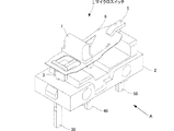
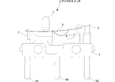
図1は、この例にかかるマイクロスイッチの外観を示す概略図である。図2は、この例にかかるマイクロスイッチのカバーを外した状態の概略図である。図3は、図2に示すA方向の平面図である。この例にかかるマイクロスイッチ1は、ベース2、共通接点端子3、常開接点端子4、常閉接点端子5、可動接触片6、押しボタン7、およびカバー8を備えている。常閉接点端子5が、この発明で言う第1の固定接点端子に相当し、常開接点端子4が、この発明で言う第2の固定接点端子に相当する。
FIG. 1 is a schematic view showing the appearance of a microswitch according to this example. FIG. 2 is a schematic view of the microswitch according to this example with the cover removed. FIG. 3 is a plan view in the A direction shown in FIG. A microswitch 1 according to this example includes a
ベース2は、樹脂を成型した絶縁性の部材である。ベース2の一方の面(ここでは、上面と言う。)には、共通接点端子3、常開接点端子4、および常閉接点端子5がこの順に並べて取り付けられている。この上面が、ベース2における共通接点端子3、常開接点端子4、および常閉接点端子5の取付面である。共通接点端子3、常開接点端子4、および常閉接点端子5は、接続端子部30、40、50がベース2を貫通し、ベース2の下面側に突出している。共通接点端子3、常開接点端子4、および常閉接点端子5は、導電性の部材である。
The
共通接点端子3、常開接点端子4、および常閉接点端子5の並び方向(図3における左右方向)を、ここではベース2の長手方向と言う。また、ベース2の長手方向に直交する方向(図3における紙面に垂直な方向)を、ベース2の幅方向と言う。ベース2は、長手方向の長さが8〜15mm程度であり、幅方向の長さが5〜8mm程度である。
The arrangement direction of the
ベース2には、共通接点端子3、常開接点端子4、および常閉接点端子5の接続端子部30、40、50を嵌挿する貫通孔が、ベース2の幅方向のほぼ中心に形成されている。したがって、共通接点端子3、常開接点端子4、および常閉接点端子5の接続端子部30、40、50は、ベース2の幅方向のほぼ中心において、ベース2の下面側に突出している。
In the
可動接触片6は、ベース2の長手方向に延びる板状の導電性の部材である。可動接触片6は、ベース2の上面側に位置し、ベース2の長手方向における一方の側を共通接点端子3に係止している。可動接触片6は、共通接点端子3に係止されていない側の端部がベース2に対して接離する方向に回動する。可動接触片6は、回動することによって、共通接点端子3に係止されていない側の端部が、常開接点端子4、または常閉接点端子5の一方から離れ、他方に接する。可動接触片6が接している常開接点端子4、または常閉接点端子5と、共通接点端子3とが導通する(共通接点端子3と、可動接触片6とは常に接触している。)。
The
押しボタン7は、可動接触片6の上に配置されている。押しボタン7がベース2の上面側に押圧されると、可動接触片6がベース2の上面側に押し下げられる。カバー8は、ベース2の上面側に位置する、共通接点端子3、常開接点端子4、常閉接点端子5、および可動接触片6を覆う形状である。押しボタン7は、カバー8の外側に突出しており、カバー8を装着した状態でベース2の上面側に押圧できるように構成している。
The
次に、共通接点端子3、常開接点端子4、および常閉接点端子5について説明する。図4は、共通接点端子、常開接点端子、および常閉接点端子をベースに取り付けた状態を示す図であり、図5は、図4においてベースの図示を省略した図である。図4、および図5は、共通接点端子3、常開接点端子4、および常閉接点端子5の間において重なりが生じない方向から見た図であり、図1、および図2とは見ている方向が異なる。
Next, the
共通接点端子3は、肉厚が0.3〜0.5mm程度の短冊状導電材にプレス加工を施して、規定の形状に打ち抜き、折り曲げることによって図示する形状に形成したものである。また、常開接点端子4、および常閉接点端子5も同様に、肉厚が0.3〜0.5mm程度の短冊状導電材にプレス加工を施して、規定の形状に打ち抜き、折り曲げることによって図示する形状に形成したものである。
The
なお、短冊状導電材にプレス加工を施して打ち抜く形状は、共通接点端子3、常開接点端子4、および常閉接点端子5で異なる。
Note that the shape of stamping and punching the strip-shaped conductive material differs between the
共通接点端子3は、図5に示すように、胴部33の一方の側に第1の係止部31、および第2の係止部32を有する接点端子部と、胴部33の他方の側にベース2の下面側に突出させる接続端子部30を形成している。第1の係止部31、および第2の係止部32は、図5から明らかなように、ベース2の長手方向における両端部を押しボタン7の押圧方向を軸にして折り曲げて形成したものである。第1の係止部31、および第2の係止部32は、ベース2の長手方向に並んでいる。第1の係止部31が、常開接点端子4、および常閉接点端子5の反対側に位置し、第2の係止部32が、常開接点端子4、および常閉接点端子5側に位置している。
As shown in FIG. 5, the
第1の係止部31、および第2の係止部32は、ベース2の幅方向において、折曲位置を挟んで両側に延びる面を有する。また、第1の係止部31、および第2の係止部32は、押しボタン7の押圧方向を軸にした折り曲げ位置を、ベース2の幅方向の中心からずらすことによって、折曲位置から折り曲げた側の端部までの長さが、折曲位置から折り曲げた側の反対側の端部までの長さよりも長くなるようにしている。共通接点端子3は、押しボタン7側から見た平面視において、ほぼH字の形状(H字の幅方向が、ベース2の長手方向である。)である。
The
図6(A)は、共通接点端子の第1の係止部を示す平面図であり、図6(B)は、共通接点端子の第2の係止部を示す平面図である。図6(A)は、図5に示すA方向から見た平面図であり、図6(B)は、図5に示すB方向から見た平面図である。第1の係止部31は、常開接点端子4、および常閉接点端子5の反対側の面に、ベース2の幅方向において、折曲位置を挟んで両側に延びる係止溝31aを形成している。この係止溝31aが形成されている面は、ほぼ平面である。第2の係止部32は、常開接点端子4、および常閉接点端子5側の面に、ベース2の幅方向において、折曲位置を挟んで両側に延びる係止溝32aを形成している。この係止溝32aが形成されている面も、ほぼ平面である。
FIG. 6A is a plan view showing a first locking portion of the common contact terminal, and FIG. 6B is a plan view showing a second locking portion of the common contact terminal. 6A is a plan view seen from the direction A shown in FIG. 5, and FIG. 6B is a plan view seen from the direction B shown in FIG. The
切り欠き部31b、32bは、押しボタン7の押圧方向を軸にした折り曲げにかかる加工精度を確保するために設けている。ベース2の幅方向における切り欠き部31b、32bの長さ(折曲位置から切り欠き部31b、32bの端部までの長さ)は、0.5mm程度である。切り欠き部31b、32bは、ベース2の幅方向における長さを抑えることによって、この切り欠き部31b、32bを挟んだ上側と、下側とがつながっている部分(以下、係止部の根元と言う。)の幅Wを長くすることができる。
The
係止部の根元の幅Wが長くなるにつれて、係止部の根元が折れるのを抑えられる。 As the width W of the base of the locking part becomes longer, the base of the locking part can be prevented from breaking.
また、共通接点端子3は、胴部33を屈曲させることにより、接続端子部30をベース2の幅方向における第1の係止部31、および第2の係止部32のほぼ中心に合わせている。
Further, the
また、常開接点端子4は、図5に示すように、胴部42の一方の側に当接部41を有する接点端子部と、胴部42の他方の側にベース2の下面側に突出させる接続端子部40を形成している。当接部41は、ベース2の上面に対向する面を有する。また、常閉接点端子5は、図5に示すように、胴部52の一方の側に当接部51を有する接点端子部と、胴部52の他方の側にベース2の下面側に突出させる接続端子部50を形成している。当接部51は、ベース2の上面に対向する面を有する。当接部41と、当接部51とは、ベース2の長手方向における位置がほぼ同じである。当接部51は、当接部41よりも上方に位置し、当接部41と対向している。
As shown in FIG. 5, the normally open contact terminal 4 protrudes to the lower surface side of the
常開接点端子4は、胴部42を屈曲させることにより、接続端子部40をベース2の幅方向における当接部41の中心に合わせている。また、常閉接点端子5は、胴部52を屈曲させることにより、接続端子部50をベース2の幅方向における当接部51の中心に合わせている。
The normally open contact terminal 4 bends the
図7は、可動接触片を示す概略図である。可動接触片6は、導電性薄板バネ材にプレス加工を施し、打ち抜いて曲げ起こすにより、ベース2の長手方向の一端側に、共通接点端子3の第1の係止部31の係止溝31aに係止する係合孔61を形成している。また、可動接触片6は、ベース2の長手方向の他端側に、ほぼ半円状の復帰バネ部62を切り起こしている。復帰バネ部62の自由端部は、共通接点端子3の第2の係止部32の係止溝32aに係止される。また、可動接触片6は、復帰バネ部62よりも他端側の端部(以下、後端部と言う。)が、常開接点端子4の当接部41、および常閉接点端子5の当接部51に当接する長さである。
FIG. 7 is a schematic view showing a movable contact piece. The
このマイクロスイッチ1の組み立てについて簡単に説明する。まず、ベース2に対して共通接点端子3、常開接点端子4、および常閉接点端子5を取り付ける。このとき、共通接点端子3、常開接点端子4、および常閉接点端子5は、ベース2の幅方向の略中心において、接続端子部30、40、50がベース2を貫通し突出する位置に取り付ける(図4に示す状態)。
The assembly of the microswitch 1 will be briefly described. First, the
可動接触片6の係合孔61に第1の係止部31を嵌挿し、係合孔61の先端側の縁部を第1の係止部31の係止溝31aに係止させる。このとき、可動接触片6の後端部は、常開接点端子4の当接部41と、常閉接点端子5の当接部51との間に位置させる。また、復帰バネ部62の自由端を第2の係止部32の係止溝32aに係止させる。そして、可動接触片6の上に押しボタン7を配置する(図2、図3に示す状態)。
The
さらに、ベース2の上面側に位置する、共通接点端子3、常開接点端子4、常閉接点端子5、および可動接触片6を覆うようにカバー8を取り付ける(図1に示す状態)。このとき、押しボタン7は、カバー8の外側に突出させる。
Further, a cover 8 is attached so as to cover the
なお、上記マイクロスイッチ1の組み立て工程においては、必要に応じて冶具を用いる。 In the assembly process of the microswitch 1, a jig is used as necessary.
次に、このマイクロスイッチ1の動作について説明する。押しボタン7が、ベース2の上面側に押圧されていない状態であるとき、復帰バネ部62のバネ力によって、可動接触片6が上方(ベース2と反対側)に付勢されている。このため、可動接触片6の後端部は、常閉接点端子5の当接部51に当接し、常開接点端子4の当接部41から離間している。したがって、共通接点端子3と常閉接点端子5とが、可動接触片6により導通している(共通接点端子3と常開接点端子4とは導通していない。)。
Next, the operation of the microswitch 1 will be described. When the
押しボタン7が押圧されると、この押しボタン7が可動接触片6をベース2側に押し下げ、可動接触片6が第1の係止部31の係止溝31aに係止されている係合孔61の縁部を支点として、後端部がベース2に近づく方向に回動する。そして、可動接触片6が復帰バネ部62の動作位置を越えると、可動接触片6が瞬時に回動し、可動接触片6の後端部が常閉接点端子5の当接部51から離間し、常開接点端子4の当接部41に当接する。すなわち、押しボタン7をベース2側に押圧したことにより、共通接点端子3と常開接点端子4とが、可動接触片6により導通する(共通接点端子3と常閉接点端子5とは導通していない。)。
When the
さらに、押しボタン7の押圧を停止すると、可動接触片6は、復帰バネ部62の付勢力により、第1の係止部31の係止溝31aに係止されている係合孔61の縁部を支点として、後端部がベース2から離れる方向に回動する。これにより、可動接触片6の後端部は、常開接点端子4の当接部41から離間し、常閉接点端子5の当接部51に当接する。すなわち、押しボタン7の押圧を停止したことにより、共通接点端子3と常閉接点端子5とが、可動接触片6により導通する(共通接点端子3と常開接点端子4とは導通していない。)。
Further, when the pressing of the
このように、マイクロスイッチ1は、押しボタン7の押圧により、可動接触片6が第1の係止部31の係止溝31aに係止されている係合孔61の縁部を支点として回動する。また、可動接触片6が第1の係止部31の係止溝31aに係止されている係合孔61の縁部を支点として回動するとき、可動接触片6が第2の係止部32の係止溝32aに係止されている復帰バネ部62の自由端が応力の作用によって動く。可動接触片6は、常開接点端子4、の当接部41および常閉接点端子5の当接部51によって、回動可能な範囲が制限されている。
As described above, the microswitch 1 is rotated around the edge of the
上述したように、可動接触片6の係合孔61の縁部を係止する第1の係止部31および、可動接触片6の復帰バネ部62の自由端を係止する第2の係止部32は、折り曲げによって円弧状になった部分が存在しない。したがって、共通接点端子3を大きくすることなく、第1の係止部31、および第2の係止部32における可動接触片6との接触領域の大きさを十分に確保することができる。したがって、マイクロスイッチ1本体を大型化することなく、回動による可動接触片6や第1の係止部31、および第2の係止部32の磨耗が抑えられる。
As described above, the
また、第1の係止部31、および第2の係止部32は、押しボタン7の押圧方向を軸にした折り曲げ位置を、ベース2の幅方向の中心からずらし、折曲位置から折り曲げた側の端部までの長さが、折曲位置から折り曲げた側の反対側の端部までの長さよりも長くしている。これにより、第1の係止部31、および第2の係止部32の根元の幅Wが短くなるのを抑え、その長さを十分に確保することができる。したがって、第1の係止部31や第2の係止部32が根元で折れて破損するのを抑えられる。
In addition, the
なお、上記の例にかかるマイクロスイッチ1は、常開接点端子4、および常閉接点端子5を備える構成としたが、常開接点端子4、または常閉接点端子5の一方を備えていない構成であってもよい。この場合、可動接触片6の回動範囲を制限するため、ストッパを設ければよい。
The microswitch 1 according to the above example is configured to include the normally open contact terminal 4 and the normally closed
また、上記の例では、可動接触片6は、復帰バネ部62が一体的に形成されているとしたが、復帰バネ部62を一体形成していない構成であってもよい。
In the above example, the
また、共通接点端子3、常開接点端子4、および常閉接点端子5の胴部33、42、52を屈曲させていない構成であってもよい。この場合には、共通接点端子3、常開接点端子4、および常閉接点端子5の接続端子部30、40、50をベース2の下面側に突出させる位置を、ベース2の幅方向の中心からずらした位置にすればよい。
Moreover, the structure which is not bending the trunk | drum 33,42,52 of the
1…マイクロスイッチ
2…ベース
3…共通接点端子
4…常開接点端子
5…常閉接点端子
6…可動接触片
7…押しボタン
8…カバー
30…接続端子部
31…第1の係止部
31a…係止溝
32…第2の係止部
32a…係止溝
33…胴部
40…接続端子部
41…当接部
42…胴部
50…接続端子部
51…当接部
52…胴部
61…係合孔
62…復帰バネ部
DESCRIPTION OF SYMBOLS 1 ...
Claims (5)
前記ベースにおける前記共通接点端子、および前記固定接点端子の取付面に対向する側に配置され、前記共通接点端子、および前記固定接点端子側に押圧される押しボタンと、
前記共通接点端子と前記固定接点端子との並び方向における、前記共通接点端子の両側において係止され、前記押しボタンの押圧によって作用する押圧力によって回動して前記共通接点端子と前記固定接点端子とを導通開閉する可動接触片と、を備え、
前記可動接触片は、前記押しボタンの押圧によって作用する押圧力に対する反力を生じさせる復帰バネ部を有し、
前記固定接点端子との並び方向における前記共通接点端子の両端部は、前記押しボタンの押圧方向を軸にして折り曲げられ、折曲位置を挟んで、前記ベースにおける前記固定接点端子との並び方向に対して直交する幅方向に延びる係止部を有し、
前記固定接点端子の反対側に位置する前記係止部は、前記可動接触片が回動するときの支点になり、
前記固定接点端子側に位置する前記係止部は、前記可動接触片の前記復帰バネ部を係止する、マイクロスイッチ。 A base with a common contact terminal and a fixed contact terminal mounted side by side;
A push button disposed on a side of the base facing the mounting surface of the common contact terminal and the fixed contact terminal, and pressed to the common contact terminal and the fixed contact terminal side;
The common contact terminal and the fixed contact terminal are locked by both sides of the common contact terminal in the arrangement direction of the common contact terminal and the fixed contact terminal, and are rotated by a pressing force acting by pressing of the push button. A movable contact piece that electrically opens and closes,
The movable contact piece has a return spring portion that generates a reaction force against a pressing force acting by pressing the push button,
Both ends of the common contact terminal in the alignment direction with the fixed contact terminal are bent with the pressing direction of the push button as an axis, and the bending position is sandwiched in the alignment direction with the fixed contact terminal in the base. A locking portion extending in the width direction orthogonal to the
The locking portion located on the opposite side of the fixed contact terminal serves as a fulcrum when the movable contact piece rotates,
The microswitch, wherein the locking portion located on the fixed contact terminal side locks the return spring portion of the movable contact piece.
前記ベースを貫通させ、前記押しボタンを配置していない側に突出させた接続端子部と、
前記ベースにおける前記幅方向の中心と、前記係止部の前記幅方向の中心とを一致させたときに、前記ベースにおける前記幅方向の中心において、前記接続端子部が突出するように屈曲させた胴部と、を設けている、請求項1、または2に記載のマイクロスイッチ。 The common contact terminal is
A connection terminal portion that penetrates the base and protrudes to the side where the push button is not disposed,
When the center in the width direction of the base matches the center in the width direction of the locking portion, the connection terminal portion is bent so as to protrude at the center in the width direction of the base. The microswitch according to claim 1, further comprising a trunk portion.
Priority Applications (2)
| Application Number | Priority Date | Filing Date | Title |
|---|---|---|---|
| JP2015130532A JP6536221B2 (en) | 2015-06-30 | 2015-06-30 | Microswitch |
| CN201610428830.3A CN106328409A (en) | 2015-06-30 | 2016-06-16 | Microswitch |
Applications Claiming Priority (1)
| Application Number | Priority Date | Filing Date | Title |
|---|---|---|---|
| JP2015130532A JP6536221B2 (en) | 2015-06-30 | 2015-06-30 | Microswitch |
Publications (2)
| Publication Number | Publication Date |
|---|---|
| JP2017016807A true JP2017016807A (en) | 2017-01-19 |
| JP6536221B2 JP6536221B2 (en) | 2019-07-03 |
Family
ID=57725191
Family Applications (1)
| Application Number | Title | Priority Date | Filing Date |
|---|---|---|---|
| JP2015130532A Active JP6536221B2 (en) | 2015-06-30 | 2015-06-30 | Microswitch |
Country Status (2)
| Country | Link |
|---|---|
| JP (1) | JP6536221B2 (en) |
| CN (1) | CN106328409A (en) |
Cited By (2)
| Publication number | Priority date | Publication date | Assignee | Title |
|---|---|---|---|---|
| WO2019051853A1 (en) * | 2017-09-14 | 2019-03-21 | 惠州市正牌科电有限公司 | High-reliability micro switch |
| US11515104B2 (en) | 2018-03-15 | 2022-11-29 | Omron Corporation | Microswitch and operating device |
Families Citing this family (4)
| Publication number | Priority date | Publication date | Assignee | Title |
|---|---|---|---|---|
| JP6881078B2 (en) * | 2017-06-22 | 2021-06-02 | オムロン株式会社 | switch |
| CN107093532B (en) * | 2017-06-26 | 2019-08-30 | 东莞市高特电子有限公司 | A kind of mouse microswitch |
| CN107342180A (en) * | 2017-08-10 | 2017-11-10 | 东莞市金倍利电器科技有限公司 | A kind of new-type microswitch structure |
| CN109119272A (en) * | 2018-09-25 | 2019-01-01 | 深圳马太亚科技有限公司 | Mute microswitch and mouse |
Citations (2)
| Publication number | Priority date | Publication date | Assignee | Title |
|---|---|---|---|---|
| JPH05342935A (en) * | 1992-06-05 | 1993-12-24 | Omron Corp | Terminal metal plate of switch |
| JPH06111677A (en) * | 1992-08-14 | 1994-04-22 | Omron Corp | Switch |
Family Cites Families (3)
| Publication number | Priority date | Publication date | Assignee | Title |
|---|---|---|---|---|
| US5875887A (en) * | 1997-05-15 | 1999-03-02 | Shin Jiuh Corp. | Contact switch assembly having a conductor that holds a movable contact plate |
| JP4760998B1 (en) * | 2010-10-12 | 2011-08-31 | オムロン株式会社 | switch |
| JP5898564B2 (en) * | 2012-05-16 | 2016-04-06 | アルプス電気株式会社 | Press switch device |
-
2015
- 2015-06-30 JP JP2015130532A patent/JP6536221B2/en active Active
-
2016
- 2016-06-16 CN CN201610428830.3A patent/CN106328409A/en active Pending
Patent Citations (2)
| Publication number | Priority date | Publication date | Assignee | Title |
|---|---|---|---|---|
| JPH05342935A (en) * | 1992-06-05 | 1993-12-24 | Omron Corp | Terminal metal plate of switch |
| JPH06111677A (en) * | 1992-08-14 | 1994-04-22 | Omron Corp | Switch |
Cited By (2)
| Publication number | Priority date | Publication date | Assignee | Title |
|---|---|---|---|---|
| WO2019051853A1 (en) * | 2017-09-14 | 2019-03-21 | 惠州市正牌科电有限公司 | High-reliability micro switch |
| US11515104B2 (en) | 2018-03-15 | 2022-11-29 | Omron Corporation | Microswitch and operating device |
Also Published As
| Publication number | Publication date |
|---|---|
| CN106328409A (en) | 2017-01-11 |
| JP6536221B2 (en) | 2019-07-03 |
Similar Documents
| Publication | Publication Date | Title |
|---|---|---|
| JP2017016807A (en) | Microswitch | |
| JP6416389B2 (en) | Conductor connection terminal and assembly method thereof | |
| CN110663139B (en) | Connecting device | |
| JP5924038B2 (en) | Terminal connection structure | |
| JP6016244B2 (en) | connector | |
| JP2020187972A (en) | Connection method, connection structure and connection terminal assembly | |
| WO2020071226A1 (en) | Female terminal | |
| US20180019079A1 (en) | Push switch | |
| TWI654636B (en) | Switching device | |
| EP1223593A2 (en) | Switch device | |
| JP2015153756A (en) | Electrical switch with actuator | |
| TWI665696B (en) | Switch | |
| JP2018022617A (en) | Card edge connector | |
| JP2007157644A (en) | Switching device | |
| CN110235216B (en) | Trigger switch | |
| JP4692404B2 (en) | Microswitch | |
| KR102224396B1 (en) | Switch | |
| JP5717307B1 (en) | Lever switch | |
| JP6212867B2 (en) | Push-button switch | |
| JP6727083B2 (en) | Switch device | |
| EP2922074B1 (en) | Reed with hinge for reed switch | |
| JP5178792B2 (en) | connector | |
| JP2007227308A (en) | Switching device | |
| JP6100421B2 (en) | Board connection structure | |
| KR20150106743A (en) | switch unit for vehicle |
Legal Events
| Date | Code | Title | Description |
|---|---|---|---|
| A621 | Written request for application examination |
Free format text: JAPANESE INTERMEDIATE CODE: A621 Effective date: 20180412 |
|
| A977 | Report on retrieval |
Free format text: JAPANESE INTERMEDIATE CODE: A971007 Effective date: 20190111 |
|
| A131 | Notification of reasons for refusal |
Free format text: JAPANESE INTERMEDIATE CODE: A131 Effective date: 20190122 |
|
| A521 | Request for written amendment filed |
Free format text: JAPANESE INTERMEDIATE CODE: A523 Effective date: 20190320 |
|
| TRDD | Decision of grant or rejection written | ||
| A01 | Written decision to grant a patent or to grant a registration (utility model) |
Free format text: JAPANESE INTERMEDIATE CODE: A01 Effective date: 20190507 |
|
| A61 | First payment of annual fees (during grant procedure) |
Free format text: JAPANESE INTERMEDIATE CODE: A61 Effective date: 20190520 |
|
| R150 | Certificate of patent or registration of utility model |
Ref document number: 6536221 Country of ref document: JP Free format text: JAPANESE INTERMEDIATE CODE: R150 |
|
| R250 | Receipt of annual fees |
Free format text: JAPANESE INTERMEDIATE CODE: R250 |