JP2017016592A - Main subject detection device, main subject detection method and program - Google Patents
Main subject detection device, main subject detection method and program Download PDFInfo
- Publication number
- JP2017016592A JP2017016592A JP2015135679A JP2015135679A JP2017016592A JP 2017016592 A JP2017016592 A JP 2017016592A JP 2015135679 A JP2015135679 A JP 2015135679A JP 2015135679 A JP2015135679 A JP 2015135679A JP 2017016592 A JP2017016592 A JP 2017016592A
- Authority
- JP
- Japan
- Prior art keywords
- main subject
- image
- area
- detection
- region
- Prior art date
- Legal status (The legal status is an assumption and is not a legal conclusion. Google has not performed a legal analysis and makes no representation as to the accuracy of the status listed.)
- Pending
Links
Images


Abstract
Description
本発明は、入力画像において主被写体の領域を検出する技術に関する。 The present invention relates to a technique for detecting a region of a main subject in an input image.
従来から、入力画像中の主被写体の領域を検出する方法が知られている。特許文献1には、過去の複数フレームの画像内で存在している累積時間が長い等、安定的に出現している被写体を主被写体として検出する技術が開示されている。 Conventionally, a method for detecting a region of a main subject in an input image is known. Patent Document 1 discloses a technique for detecting a stably appearing subject as a main subject such as a long accumulated time existing in images of a plurality of past frames.
そして、このような主被写体領域検出の処理が例えばデジタルカメラなどの撮像装置内で行われることにより、主被写体にオートフォーカス(AF)を調節したり、主被写体に対して自動追尾を行うことができるようになる。 Such main subject area detection processing is performed in an imaging device such as a digital camera, so that autofocus (AF) can be adjusted for the main subject or automatic tracking can be performed for the main subject. become able to.
しかしながら、特許文献1に開示される技術のように、複数フレームの画像にわたって長く安定的に写っているものを主被写体とするだけでは、撮影者の意図を誤って主被写体を検出してしまう可能性がある。 However, as in the technique disclosed in Patent Document 1, it is possible to detect the main subject by mistake of the photographer's intention only by using the main subject as a long and stable image over a plurality of frames. There is sex.
例えば、動かない物体(例えば道路標識等)を撮影しているときに、動きのある物体が画像内に入り込んできた場合(例えば車が入り込んできた場合)、従来の特許文献1の方法では道路標識を主被写体として検出することになる。しかしながら、撮影者は、道路標識が写るような構図で車を撮影しようとして、車が画角に入ってくるのを待っていたということもある。この場合には、車が主被写体と検出されることが好ましく、画像に長く安定的に写っていたものを主被写体と検出するだけでは、撮影者の意図に反した主被写体検出をしてしまうことがあった。本発明は、撮影者の意図に反した主被写体検出を抑制することを目的とする。 For example, when a moving object has entered the image (for example, a car has entered) while shooting a non-moving object (for example, a road sign), the conventional patent document 1 uses a road. The sign is detected as the main subject. However, the photographer may have waited for the car to come into the angle of view, trying to photograph the car in a composition in which the road sign is reflected. In this case, it is preferable that the car is detected as the main subject, and the main subject that is contrary to the photographer's intention is detected only by detecting the main subject as a long and stable image. There was a thing. An object of the present invention is to suppress detection of a main subject against the photographer's intention.
以上の課題を解決するために、本発明は、特定時点における画像の主被写体の領域を検出する主被写体検出装置であって、前記特定時点より前の、時系列に連続する複数の画像を取得する画像取得手段と、前記取得手段により取得された複数の画像において存在する頻度が所定の回数以上の物体を検出する物体検出手段と、前記物体検出手段により検出された物体の情報に基づいて、前記特定時点における画像において主被写体の第1候補領域を検出する第1検出手段と、前記特定時点における画像において主被写体の領域が検出された場合に、当該検出された主被写体の領域の情報が供される機能を取得する機能取得手段と、前記機能取得手段により取得された機能に応じて、前記特定時点における画像の特徴量を算出する特徴量算出手段と、前記特徴量算出手段により算出された特徴量に基づいて、前記特定時点における画像において主被写体の第2候補領域を検出する第2検出手段と、前記第1検出手段により検出された第1候補領域と、前記第2検出手段により検出された第2候補領域とに基づき、前記特定時点における画像の主被写体の領域を検出する最終検出手段と、を有することを特徴とする。 In order to solve the above problems, the present invention is a main subject detection device that detects a region of a main subject of an image at a specific time point, and acquires a plurality of continuous images in time series before the specific time point. On the basis of the information on the object detected by the object detecting means, the object detecting means for detecting an object having a predetermined frequency or more in the plurality of images acquired by the acquiring means, First detection means for detecting a first candidate region of the main subject in the image at the specific time point, and when the main subject region is detected in the image at the specific time point, information on the detected main subject region is obtained. A function acquisition unit that acquires a function to be provided; and a feature amount calculation unit that calculates a feature amount of the image at the specific time according to the function acquired by the function acquisition unit. , Second detection means for detecting a second candidate area of the main subject in the image at the specific time point based on the feature quantity calculated by the feature quantity calculation means, and a first candidate detected by the first detection means And final detection means for detecting a main subject area of the image at the specific time point based on the area and the second candidate area detected by the second detection means.
以上の構成によれば、本発明は、撮影者の意図に反した主被写体の検出を抑制することが可能になる。 According to the above configuration, the present invention can suppress the detection of the main subject against the photographer's intention.
[第1の実施形態]
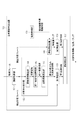
以下、図面を参照して本発明の実施形態を詳細に説明する。図1は、本実施形態に係る主被写体検出装置100の構成を示す概略ブロック図である。主被写体検出装置100は、画像取得部101、対象物体検出部102、第1検出部103、機能取得部104、特徴量算出部105、第2検出部106、最終検出部107、顕著領域検出部108、同一物体領域特定部109、および出現頻度算出部110を備える。本実施形態に係る主被写体検出装置100は、半導体集積回路(LSI)を用いて実現される。例えば、デジタルカメラのような撮像装置に備えられた半導体集積回路が前述の主被写体検出装置としての機能を実現するようにしてもよく、この場合、撮像装置自体が本実施形態の主被写体検出装置100に相当する。
[First Embodiment]
Hereinafter, embodiments of the present invention will be described in detail with reference to the drawings. FIG. 1 is a schematic block diagram illustrating a configuration of a main
主被写体検出装置100は、単体の装置として構成されていてもよい。つまり、主被写体検出装置100は、CPU(CentralProcessingUnit)、ROM(ReadOnlyMemory)、RAM(RandomAccessMemory)、HDD(HardDiskDrive)等のハードウェア構成を備える。そして、CPUがROMやHDD等に格納されたプログラムを実行することにより、例えば、後述する各機能構成やフローチャートの処理が実現される。RAMは、CPUがプログラムを展開して実行するワークエリアとして機能する記憶領域を有する。ROMは、CPUが実行するプログラム等を格納する記憶領域を有する。HDDは、CPUが処理を実行する際に要する各種のプログラム、閾値に関するデータ等を含む各種のデータを格納する記憶領域を有する。
The main
以下、本実施形態の説明では、主被写体検出装置100がデジタルカメラとして構成されている場合を例に説明する。まず、画像取得部101は、撮像部(イメージセンサ等)から逐次入力される入力画像(動画フレーム)を取得し、取得した入力画像(動画フレーム)を対象物体検出部102、第1検出部103、特徴量算出部105へと出力する。なお、このような逐次入力される画像は、デジタルカメラのスルー表示の機能等にも供される。
Hereinafter, in the description of the present embodiment, a case where the main
対象物体検出部102は、複数フレームで高頻度に存在している物体(以下、取込み対象物体と称す)を検出する。対象物体検出部102の処理の概要について簡単に説明する。まず、対象物体検出部102は、取込み対象物体の候補を探索し、その候補が複数フレームにわたって長く映っているかどうかを判断する。その際、対象物体検出部102は、異なるフレームで探索された候補が同一のものであるか否かの判定を行い、同一と判定された候補が複数フレームにわたって存在すれば、長く映っていると判断する。そして、対象物体検出部102は、複数フレームにわたって長く映っていると判断した取込み対象物体に関する情報(位置やサイズ、色等)を出力する。
The target
次に、対象物体検出部102の詳細を説明するために、対象物体検出部102を構成するサブブロックごとの処理について説明する。顕著領域検出部108は、動画フレームの一枚一枚を入力画像として逐次取得し、各入力画像から顕著な領域を探索する。顕著領域の探索手法としては、種々の公知手法を用いることができる。例えば、非特許文献1に記載されている中心−周囲(center−surround)差分法等を用いればよく、画像の各画素に小領域を設定し、その小領域と周囲の領域との特徴量の差分を顕著度として算出する等により顕著領域が検出される。
Next, in order to explain the details of the target
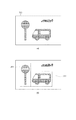
図2は、入力画像、及び顕著領域検出部108により探索された顕著領域の例を示す。図2(a)は、画像取得部101により取得され、顕著領域検出部108へと入力された入力画像201を示している。入力画像201には、標識202と車203が写っている。
FIG. 2 shows an example of the saliency area searched by the input image and the saliency
顕著領域検出部108は、この入力画像201に対して上記非特許文献1に記載されるような手法を用いて顕著度の算出を行い、顕著度を画素値とする顕著度マップを得る。この顕著度マップを所定の閾値で二値化し、所定の閾値以上の顕著度を有する高顕著領域だけを抽出する。
The
図2(b)は、検出した高顕著度領域の外接矩形を入力画像201に重ねて表示している。矩形205及び206が、標識202及び車203に対して設定された高顕著度領域の外接矩形の領域である。顕著領域検出部108は、検出した高顕著領域を取込み対象物体の候補として、その情報を同一物体領域特定部109に出力する。ここで出力する情報は、例えば、外接矩形205、206で切り取られた画像及び、外接矩形205、206の入力画像201内での位置である。
FIG. 2B displays the circumscribed rectangle of the detected high saliency area superimposed on the
同一物体領域特定部109は、異なるフレーム(入力画像)で検出された取込み対象物体の候補が、同一の物体を撮影したものであるか否かの判定を行う。同一物体か否かの判定は、異なるフレームに対して顕著領域検出部108から出力された候補領域同士の相関を算出することにより判定される。
The same object
図2に戻り、同一物体領域特定部109における同一物体領域の判定処理について説明する。図2(c)には、入力画像201に続く(時間的に連続する)入力画像207が図示されている。入力画像207において、標識208及び車209は、図2(a)の標識202及び車203に対応しており、車209は入力画像201の時点から少し動いている。また、入力画像207には、新たにフレーム中に入ってきた飛行機210が存在している。
Returning to FIG. 2, the same object region determination process in the same object
図2(d)は、検出した高顕著度領域の外接矩形を入力画像207に重ねて表示すものであり。矩形212、213、及び214が、標識208、車209及び飛行機210に対して設定された高顕著度領域の外接矩形の領域である。
FIG. 2D shows the circumscribed rectangle of the detected high saliency area superimposed on the
このように、ある時点の入力画像201には、取込み対象物体の候補領域として矩形205、206の二つが存在し、異なる時点の入力画像207には、取込み対象物体の候補領域として矩形212、213、214の三つが存在している。そして、同一物体領域特定部109は、異なる時点のフレーム(入力画像)の候補領域同士の相関をとる。上述した図2の場合には、「205と212」、「205と213」、「205と214」、「206と212」、「206と213」、「206と214」の6通りの組み合わせに対して相関係数を算出する。なお、相関係数を算出する手法にあたっては、種々の公知技術を用いることができ、例えば正規化相関を算出すればよい。正規化相関を算出する場合、相関をとる対象の候補領域のサイズをアフィン変換等で揃える必要がある。
As described above, the
このように、同一物体領域特定部109は、異なるフレーム(入力画像)の候補領域同士の相関をとり、得られた相関係数に対して所定の閾値により閾値処理を行う。そして、閾値を超えた相関係数をもつ候補領域同士は、同一物体として判定される。図2の例では、「205と212」、「206と213」が同一物体領域として判定される。どの候補領域同士が同一物体領域と判定されたのかという判定結果は、出現頻度算出部110に出力される。
In this way, the same object
出現頻度算出部110は、同一物体領域特定部109から出力される判定結果に基づき、各取込み対象物体の候補が動画フレーム中に何度出現したかをカウントする。図2に示した2フレームの例では、候補205(212)の出現頻度は2回、候補206(213)の出現頻度は2回、候補214の出現頻度は1回となる。同一物体領域特定部109からは同一と判定された候補(対)が出力されるので、これを辿ることで3フレーム以上にわたっても同一物体に対する出現頻度をカウントしていくことができる。
Based on the determination result output from the same object
出現頻度算出部110は、予め決められたフレーム枚数中に、所定の回数以上、出現している取込み対象物体の候補が現れると、その候補を取込み対象物体とする。例えば、2フレーム中で2回以上の出現回数であれば、その候補を取込み対象物体とする、というように予め決められているとすると、図2の場合、候補206(213)及び候補205(212)が取込み対象物体となる。
When the appearance
出現頻度算出部110は、以上の処理の結果、取込み対象物体を示す情報(以下、取込み対象物体情報と称す)を第1検出部103に出力する。例えば、出力結果の取込み対象物体情報として、取込み対象物体212、213の切取り画像及び、それらの入力画像207内での位置に関する情報が出力される。なお、取込み対象物体情報としては、取込み対象物体212と205であれば、どちらの切取り画像を出力してもよいが、本実施形態では時間的に新しい取込み対象物体212を出力とする。これは、主被写体を検出しようとしている画像と時間的に近いフレームから切り取った方が、後に説明する第1候補領域の探索がより精度よく探索できるからである。
As a result of the above processing, the appearance
以上の説明のようにして、対象物体検出部102は取込み対象物体を検出する。これにより、動画フレーム中で出現回数の高い物体が取込み対象物体として特定されることになる。動画フレーム中で出現回数の高い物体は、撮影者が撮影画像に取り込みたい物体である可能性が高いので、このような物体を特定することは、撮影者の意図を反映した主被写体検出を実現する上で必要な処理であるといえる。
As described above, the target
なお、このような、撮影者はどのような物体を撮影しようとしているのかを知るための処理は、実際に主被写体検出を行う時点のフレームよりも以前の動画フレームに対して行っておく必要がある。従って、対象物体検出部102における処理は、動画フレームを構成する静止画像が入力される度に行われることになる。すなわち、本実施形態の主被写体検出装置100(デジタルカメラ)でも、対象物体検出部102は、シャッターを押して記録するか否かに関係なく、画像が入力される度に、言わばバックグラウンドの処理として上述の処理が実行される。
It should be noted that such processing for knowing what kind of object the photographer is going to shoot needs to be performed on a moving image frame before the frame at the time of actual main subject detection. is there. Therefore, the processing in the target
図1の説明に戻ると、第1検出部103は、対象物体検出部102より取得した取込み対象物体情報を用いて、画像取得部101から入力された主被写体検出を行うフレーム(以下、検出対象フレームと称す)のどこに取込み対象物体があるのかを探索する。本実施形態において、その探索方法は特に限定されるものではない。例えば、対象物体検出部102から取込み対象物体情報として出力される取込み対象物体の切り出し画像をテンプレートとして、テンプレートマッチングにより取込み対象物体を探索することができる。
Returning to the description of FIG. 1, the
図3は、本実施形態における第1検出部103の処理を説明する図である。図3(a)は、検出対象フレーム301を示している。この検出対象フレーム301に対して、取込み対象物体212、213をテンプレートとして、テンプレートマッチングすることで、検出対象フレーム301中のどこに取込み対象物体212、213が存在するかを特定する。図3(b)は、テンプレートマッチングによる取込み対象物体特定の処理の結果を示している。同図では、矩形領域303、304が取込み対象物体212、213の存在する場所として特定されている。第1検出部103で特定、検出された領域は、以下、第1候補領域と称す。本実施形態では、矩形領域303、304の領域が第1候補領域となる。
FIG. 3 is a diagram for explaining the processing of the
または、対象物体検出部102と同様の処理により取込み対象物体を検出してもよい。この場合、顕著領域検出部108と同様の処理により高顕著領域を抽出し、続いて、同一物体領域特定部109で行ったような相関演算を抽出した高顕著領域と取込み対象物体の切り出し画像との間で行えばよい。第1検出部103で特定、検出された領域(第1候補領域)に関する情報は、第1検出部103から最終検出部107へ出力される。
Alternatively, the capture target object may be detected by a process similar to that of the target
機能取得部104は、ユーザにより指定された、装置(デジタルカメラ)で実行可能な機能に関する情報を取得する。ここで言う機能とは、主被写体検出結果を用いて実現することができるアプリケーションのことを指し、例えば、背景技術の段で例を挙げたような、オートフォーカス(AF)機能や自動追尾機能等である。機能取得部104は、これから撮影しようとする画像に対して、これらの機能のうちどれを適用させようとするのかに関する情報を取得する。例えば、主被写体に対して自動追尾機能を利用して撮影を行いたいと撮影者が考え、装置(デジタルカメラ)に対してそのように設定をしていれば、機能取得部104は、その設定された情報(自動追尾機能)を取得する。
The
一般に、主被写体検出結果を利用する機能(以下、検出結果利用機能)として、どの機能が選択されているのかという点においても、撮影者の意図を推定するヒントがある。つまり、自動追尾機能を選択したということは、撮影者は主被写体として動きを持つ物体を撮影したいのではないかという推察ができる。また、AF機能を選択したのであれば、撮影者は画像中の前景にある物体を主被写体として撮影したいのではないかと考えられる。 In general, there is a hint for estimating a photographer's intention in terms of which function is selected as a function that uses a main subject detection result (hereinafter referred to as a detection result use function). In other words, the fact that the automatic tracking function has been selected can be inferred that the photographer wants to photograph an object having a motion as the main subject. If the AF function is selected, the photographer may want to photograph the object in the foreground in the image as the main subject.
機能取得部104は、撮影しようとしている撮影対象画像に対して設定された機能の情報を取得し、取得した機能を示す情報(利用機能情報)を特徴量算出部105に出力する。本実施形態では、以下説明するように、検出結果利用機能として何が選択されているのかということに基づいて主被写体の第2候補領域を検出することも行う。
The
特徴量算出部105は、検出結果利用機能ごとに算出すべき特徴量(以下、算出特徴量)が予め対応付けて設定されており、入力される利用機能情報に対応した特徴量の算出を、画像取得部101から入力された検出対象フレームに対して行う。ここで、算出特徴量の種類は、検出結果利用機能に有用な特徴量が対応付けられている。例えば、検出結果利用機能が自動追尾機能であれば、物体の動きを検出するような特徴量が算出特徴量として対応付けられ、またAF機能であれば、前景と背景を分離できるような特徴量が算出特徴量として対応付けられる。
The feature
物体の動きを検出するために適した特徴量としては、例えば非特許文献2に開示されているオプティカルフロー等の各画素における速度ベクトルが挙げられる。動きの検出の場合は、一枚の検出対象フレームだけから検出することは困難であるので、検出対象フレームの前のフレームも合わせて特徴量算出部105に入力する必要がある。あるいは、カメラが動いてない場合には、フレーム間差分によっても動きの特徴量を算出できる。前景と背景とを分離できるような特徴量も、種々の公知技術を用いることができ、例えば特許文献2に開示される手法により算出される色特徴量などでよい。
As a feature quantity suitable for detecting the motion of an object, for example, a velocity vector in each pixel such as an optical flow disclosed in Non-Patent Document 2 can be cited. In the case of motion detection, since it is difficult to detect from only one detection target frame, it is necessary to input the frame preceding the detection target frame together to the feature
以上のように、特徴量算出部105は、検出結果利用機能ごとに定められた種類の特徴量を算出し、その算出した特徴量を各画素の画素値とする特徴量マップを作成する。そして、作成した特徴量マップは第2検出部106に出力する。機能取得部104によって取得された機能に対応する特徴量が複数ある場合は、複数の特徴量マップを作成し、出力する。
As described above, the feature
第2検出部106は、入力された特徴量マップを用いて、検出結果利用機能にとって有用な領域を検出する。入力される特徴量マップは、検出結果利用機能にとって有用な特徴量を算出した結果であるので、特徴量マップを所定の閾値で閾値処理し、閾値を超えるような領域を主被写体の第2候補領域として検出する。 The second detection unit 106 detects a region useful for the detection result utilization function using the input feature amount map. Since the input feature quantity map is a result of calculating a feature quantity useful for the detection result utilization function, the feature quantity map is subjected to threshold processing with a predetermined threshold, and an area exceeding the threshold is set as the second candidate for the main subject. Detect as a region.
図4は、第2検出部106の処理の詳細を説明するための図である。ここでは、検出結果利用機能として自動追尾機能が設定されている場合について説明する。その場合、特徴量算出部105では、動きのある領域に対して高い値を持つ特徴量マップが作成され、出力される。図4(a)のように示される検出対象フレーム401に対して、物体の動きを検出するのに適した特徴量の算出を行い、閾値処理することで、検出対象フレーム401内のどこに動きの大きい領域が存在するかを特定することができる。なお、一枚のフレームだけでは動きに関する特徴量の算出はできないので、検出対象フレーム401だけでなく、その前のフレーム(不図示)も用いて動きの特徴量を算出する。具体的には、例えば、検出対象フレーム401とその前のフレームとで差分を算出し、閾値処理をする。図4(b)は、検出対象フレーム401において、動きの大きな領域として特定された領域403、404を示している。第2検出部106は、このような動きの大きい領域を探索し、これら領域(403、404)を第2候補領域として特定する。
FIG. 4 is a diagram for explaining details of the processing of the second detection unit 106. Here, a case where the automatic tracking function is set as the detection result utilization function will be described. In this case, the feature
最終検出部107は、第1検出部103から入力される第1候補領域と、第2検出部106から入力される第2候補領域とに基づき、主被写体検出結果として、最終的な主被写体の領域を検出する。本実施形態では、第1候補領域および第2候補領域に共通して存在する領域を最終的な主被写体領域として検出する。最終検出部107は、主被写体情報として、検出した主被写体領域の位置やサイズ、さらには、検出領域のスコア(主被写体らしさ)を出力する。主被写体検出スコアの算出は、検出領域の位置やサイズ、第1候補領域を検出するときに得られる相関値、第2候補領域を検出するときに得られる特徴量値等の各情報を重み付き加算する等の演算を行い、算出すればよい。重み付き加算の重み値は、多数の画像(サンプル)から公知の学習手法により学習して決定することができる。
The
ここで、最終検出部107の処理の詳細について、図3および図4を用いて説明する。図3の検出対象フレーム301、及び図4の検出対象フレーム401は同じフレーム(入力画像)であり、このとき、第1候補領域として領域303、304が特定され、第2候補領域として領域403、404が特定される。本実施形態の例では、両候補領域に共通して存在する領域を最終的な主被写体検出領域として検出するので、最終的な主被写体検出領域は領域304(あるいは領域403)となる。
Here, details of the processing of the
なお、本実施形態において、第1候補領域と第2候補領域とに共通して存在する領域がなければ、最終検出部107は主被写体なしと判断する。両候補領域の共通領域がないということは、主被写体として確実な領域が存在しないことを意味するので、その場合は主被写体なしと出力することで、後に利用する機能において主被写体の誤検出を抑制することができる。主被写体領域を誤検出すると、撮影者に不快感や違和感を与えてしまう可能性があるので、共通の領域がない場合には、主被写体なしとすることで、その可能性を低減している。
In the present embodiment, if there is no common area between the first candidate area and the second candidate area, the
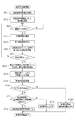
次に、主被写体検出装置100による主被写体検出処理の詳細について説明する。図5は、本実施形態に係る主被写体検出処理の処理手順を示すフローチャートである。ここでは、あるタイミング(特定時点)で入力された検出対象フレーム(入力画像)について、主被写体領域の検出をする処理を説明するものである。
Next, details of main subject detection processing by the main
図5に示すフローチャートにおいて、まずステップS501では、機能取得部104が設定された検出結果利用機能に関する情報を取得する。そして、ステップS502において、特徴量算出部105は、機能取得部104によって取得された検出結果利用機能に応じて、算出すべき特徴量を決定する。以上のステップS501、S502の処理は、検出対象フレームが取得されるタイミング(特定時点)よりも前に行われていれば、任意のタイミングに行うことができる。
In the flowchart shown in FIG. 5, first, in step S501, the
ステップS503において、画像取得部101は、動画フレーム(入力画像)の入力を判断し、画像が入力されれば、入力画像は対象物体検出部102へと渡され、処理はステップS504に進む。ステップS504では、対象物体検出部102の顕著領域検出部108が取込み対象物体の候補として高顕著領域を検出する。そして、続くステップS505において、同一物体領域特定部109が、異なるフレーム(入力画像)において検出された取込み対象物体の候補が同一の物体であるか否かの判定を行い、同一物体領域を特定する。そして、処理はステップS506に進み、出現頻度算出部110は、同一物体領域特定部109の判定結果に基づき、各取込み対象物体の候補の出現回数をカウントする。ステップS504〜S506の処理により、取込み対象物体の特定が行われる。この取込み対象物体の特定は、あるタイミング(特定時点)で入力される検出対象フレームよりも時間的に前のタイミングで逐次的に取得される複数フレームを用いて、予め行われているものである。
In step S503, the
そして、あるタイミング(特定時点)で検出対象フレームが入力され、ステップS507において、主被写体検出装置100は、処理対象となる入力画像に対して主被写体検出処理を行うか否か判断する。入力画像に対して、主被写体検出処理を行うと判断した場合、処理はステップS508以降に進む。まず、ステップS508で、第1検出部103は、テンプレートマッチング等の手法により、画像取得部101から入力された検出対象フレームから取込み対象物体を探索し、第1候補領域を検出する。
Then, a detection target frame is input at a certain timing (a specific time), and in step S507, the main
次に、ステップS509では、特徴量算出部105が、ステップS502で決定した種類の特徴量を、検出対象フレーム、及び必要に応じてそれ以前のフレームとから算出し、特徴量マップを作成する。そして、ステップS510では、第2検出部106が、特徴量算出部が算出した特徴量マップに基づいて、第2候補領域を検出する。なお、図5に示すフローチャートでは、ステップS504〜S506の処理の後に、ステップS508〜S510の処理を行うようにしている。しかし、同一の画像に対してステップS504〜S506の処理とステップS508〜S510の処理の両方を行う場合には、どちらを先に行っても構わないし、並列して同時に処理してもよい。
Next, in step S509, the feature
続いて、ステップS511において、最終検出部107は、第1候補領域と第2候補領域の共通領域の有無を判定する。そして、ステップS511の判定の結果、共通領域があれば、処理はステップS512に進み、最終検出部107は、その共通領域の情報を主被写体検出の最終候補領域として出力する。一方、共通領域がなければ、処理はステップS513に進み、最終検出部107は、検出対象フレームには主被写体がないと判定し、その結果を出力する。
Subsequently, in step S511, the
以上のように、本実施形態の主被写体検出装置100は、ある特定時点より前のフレーム群(複数の画像)から、撮影者が撮影する画像に取り込もうとしている取込み対象物体を検出する(第1候補領域の検出)。また、これと同時に、主被写体検出の結果が供されるアプリケーションにとって意味のある物体領域の検出を行う(第2候補領域の検出)。撮像装置(カメラ)の画角を決定するのは撮影者であるので、画角中に何が高頻度で存在しているかを調べることは、ある特定時点で撮影しようとする画像における撮影者の意図を推定することにつながる。また、主被写体検出の結果をどのような機能(アプリケーション)に利用するのかを設定するのも撮影者であるので、何のために主被写体を推定するのかを知ることも、ある特定時点で撮影しようとする画像における撮影者の意図を推定することにつながるといえる。
As described above, the main
本実施形態では、このように異なる二つの観点で撮影者の意図を推定して候補領域を検出し、両候補領域から最終的な主被写体候補領域として特定するものである。このように多層的に撮影者の意図を推定することで、本実施形態では、撮影者の意図に反した主被写体の検出を抑制することが可能になる。そのため、この主被写体検出結果を利用したアプリケーションを操作する撮影者に対し、主被写体検出結果の誤検出に伴う不快感や違和感を低減させることができる。 In this embodiment, the photographer's intention is estimated from two different viewpoints as described above to detect a candidate area, and specify the final main subject candidate area from both candidate areas. As described above, by estimating the photographer's intention in multiple layers, in this embodiment, it is possible to suppress detection of the main subject against the photographer's intention. Therefore, it is possible to reduce discomfort and discomfort associated with erroneous detection of the main subject detection result for the photographer who operates the application using the main subject detection result.
例えば、特許文献1の技術のように、画角中に何が高頻度で存在するかを調べること(第1候補領域の探索)のみで主被写体を推定すると、図3の例では、領域303或いは304が主被写体候補領域として特定されることになる。具体的には、領域303、及び304の両方が主被写体領域として判定されるか、より安定している(動いていない)被写体である領域303を主被写体領域と判定される。これに対して、本実施形態の主被写体検出方法では、主被写体検出結果を何のために利用するのか(例えば自動追尾機能のため)という情報も手掛かりとして使用する。これにより、本実施形態は、動きのある物体を主被写体として撮影したいのではないか、という撮影者の意図を反映して、領域304(あるいは領域403)を主被写体領域として検出することが可能となる。これにより、本実施形態は、撮影者の意図に反した主被写体の検出を抑制することが可能になる。
For example, as in the technique of Patent Document 1, when the main subject is estimated only by examining what is frequently present in the angle of view (searching for the first candidate area), in the example of FIG. Alternatively, 304 is specified as the main subject candidate area. Specifically, both the
[第1の実施形態の変形例]
上述の第1の実施形態では、第1候補領域と第2候補領域の共通領域がなければ、最終検出部107は、主被写体なしと判定するようにしていた。そこで、第1の実施形態の変形例として、最終検出部107が主被写体なしと判定した場合、そのタイミングで第2候補領域として特定した領域の情報を、続くフレーム(時間的にその後のフレーム)における処理に利用する形態について説明する。なお、第1の実施形態で既に説明をした構成については、同一の符号を付し、その説明は省略する。
[Modification of First Embodiment]
In the first embodiment described above, if there is no common area between the first candidate area and the second candidate area, the
まず、図6を用いて、本変形例の主被写体検出方法の概要を説明する。図6(a)は、画像取得部101が逐次的に取得する入力画像を時系列に並べたものである。図6(b)、(c)には、図6(a)の各入力画像に対して検出される第1候補領域、第2候補領域を示している。ここでは、上述の第1の実施形態と同様に、検出結果利用機能として自動追尾機能が設定されており、また、フレーム601(及びそれ以前のフレーム)には、フレーム内に「標識」が存在している場合を示している。
First, the outline of the main subject detection method of this modification will be described with reference to FIG. FIG. 6A shows the input images sequentially acquired by the
このような場合に、フレーム602が検出対象フレームとして入力されると、第1の実施形態では、第1候補領域として「標識」、第2候補領域として「飛行機」が検出される。そして、最終的な主被写体検出結果は、第1候補領域と第2候補領域の共通領域がないために、主被写体なしと判断される。本変形例では、このような場合に、第2候補領域として検出された領域に含まれる物体を、次のタイミングの検出対象フレームでの主被写体検出処理では、取込み対象物体に追加するものである。 In such a case, when the frame 602 is input as a detection target frame, in the first embodiment, “signpost” is detected as the first candidate region and “airplane” is detected as the second candidate region. The final main subject detection result is determined to have no main subject because there is no common area between the first candidate area and the second candidate area. In this modification, in such a case, the object included in the region detected as the second candidate region is added to the capture target object in the main subject detection process in the detection target frame at the next timing. .
図6に示す本変形例の場合、フレーム602のタイミングで第2候補領域として検出した領域は、次の検出対象フレーム603に対して実行される主被写体検出処理では、取込み対象物体に追加され、処理される。そのため、検出対象フレーム603に対して検出される第1候補領域は「標識」と「飛行機」、第2候補領域は「飛行機」となり、最終的な主被写体検出領域として「飛行機」が出力されることになる。また、その次の検出対象フレーム604でも同様の出力結果となる。 In the case of this modification shown in FIG. 6, the region detected as the second candidate region at the timing of the frame 602 is added to the capture target object in the main subject detection process executed for the next detection target frame 603, It is processed. Therefore, the first candidate area detected for the detection target frame 603 is “signpost” and “airplane”, the second candidate area is “airplane”, and “airplane” is output as the final main subject detection area. It will be. The same output result is obtained for the next detection target frame 604.
本変形例がこのように処理を行う理由は、撮影者が検出結果利用機能として自動追尾機能を選択したということは、動いている物体を主被写体として撮影したいのであろうと推測しているからである。つまり、画角内で高頻度に存在している物体(取込み対象物体)が動かない物体であるなら、これは主被写体でないと判断し、そういう構図(「標識がある構図」)において、動く物体(「飛行機」)が画角中に入ってくるのを待っていると推測しているからである。これは、本変形例が、主被写体検出結果をどの機能(アプリケーション)を利用しようとしているのかという推測を、特に重視しているということである。このような推測に基づく主被写体検出を実現するために、本変形例では上述のような処理を行っている。 The reason why this modification performs the processing in this way is that the photographer has selected the automatic tracking function as the detection result utilization function, because it is assumed that he / she wants to photograph a moving object as the main subject. is there. In other words, if an object that frequently exists in the angle of view (capture target object) is an object that does not move, it is determined that this is not the main subject, and in such a composition ("composition with a sign"), a moving object This is because it is assumed that it is waiting for ("Airplane") to enter the angle of view. This means that the present modification particularly emphasizes the estimation of which function (application) the main subject detection result is to be used. In order to realize main subject detection based on such estimation, the above-described process is performed in the present modification.
図7は、本変形例における主被写体検出処理の処理手順を示すフローチャートである。第1の実施形態と異なる点は、ステップS511において、第1候補領域と第2候補領域とに共通領域がないと判断され、主被写体なしと判断した場合に、処理をステップS701に進めることである。このステップS701では、最終検出部107が、検出対象フレームにおいて第2候補領域として検出された領域を、次のタイミングの検出対象フレームの処理において取込み対象物体の領域に追加する。追加された取込み対象物体領域は、次の検出対象フレームに対する第1候補領域の検出において使用されることになる。
FIG. 7 is a flowchart showing a processing procedure of main subject detection processing in the present modification. The difference from the first embodiment is that in step S511, if it is determined that there is no common area in the first candidate area and the second candidate area, and if it is determined that there is no main subject, the process proceeds to step S701. is there. In step S701, the
なお、動画フレームによっては、ステップS701において、わざわざ取込み対象物体として追加しなくても、いずれ時間がたてば、第1候補領域として検出されなかった領域も(例えば図6の602の飛行機)、取込み対象物体として検出されることもある。しかしながら、ステップS701のように明に取込み対象物体として追加した方が、早期に追従できる効果が期待できる。 Note that, depending on the moving image frame, an area that is not detected as the first candidate area after some time (eg, the airplane 602 in FIG. 6) without being added as an object to be captured in step S701 after some time. It may be detected as an object to be captured. However, the effect of being able to follow early can be expected when the object is clearly added as a capture target object as in step S701.
[第2の実施形態]
次に、本発明の第2の実施形態として、第1候補領域と第2候補領域に共通領域がない場合を3通りに場合分けし、それぞれで異なる検出結果を出力する形態について説明する。なお、第1の実施形態で既に説明をした構成については、同一の符号を付し、その説明は省略する。
[Second Embodiment]
Next, as a second embodiment of the present invention, a mode in which the first candidate region and the second candidate region do not have a common region is classified into three cases and different detection results are output for each case will be described. In addition, about the structure already demonstrated by 1st Embodiment, the same code | symbol is attached | subjected and the description is abbreviate | omitted.
第1候補領域と第2候補領域に共通領域がない場合には、以下の3通りがある。すなわち、「1.第1候補領域も第2候補領域も存在するが、共通領域がない場合」、「2.第1候補領域は存在するが、第2候補領域がない場合」、「3.第1候補領域はないが、第2候補領域は存在する場合」である。 When there is no common area between the first candidate area and the second candidate area, there are the following three types. That is, “1. When there is a first candidate area and a second candidate area but no common area”, “2. When there is a first candidate area but no second candidate area”, “3. This is a case where there is no first candidate area but a second candidate area exists ”.
まず、「1.第1候補領域も第2候補領域も存在するが、共通領域がない場合」は、次のようなケースである。すなわち、取込み対象物体を手がかりとして検出した結果(第1候補領域)と、検出結果利用機能を手がかりとして検出した結果(第2候補領域)とで、両方を満足するような領域が存在しなかったということである。従って、この場合は、本実施形態でも、その検出対象フレームに対しては主被写体なしと判定する。 First, “1. When both the first candidate area and the second candidate area exist but there is no common area” is as follows. That is, there is no region that satisfies both the result (first candidate region) detected using the capture target object as a clue and the result detected using the detection result utilization function (second candidate region). That's what it means. Therefore, in this case, in this embodiment, it is determined that there is no main subject for the detection target frame.
次に「2.第1候補領域は存在するが、第2候補領域がない場合」は、検出結果利用機能情報を手がかりとした領域が検出されなかった場合である。このようなケースは、例えば、検出結果利用機能として自動追尾が設定されている場合、じっとしている物体(動物等)が動くのを待ち構えているような場面が想定される。物体がじっとしている間は動きがないので、第2候補領域は検出されない。しかしながら、このような場合には、じっとしている動物を主被写体としても問題はなく、その後に動き始めれば、それを自動追尾すればよい。従って、この2番目の場合には、第1候補領域の結果を主被写体検出結果として出力する。 Next, “2. The first candidate area exists but the second candidate area does not exist” is a case where an area based on the detection result use function information is not detected. In such a case, for example, when automatic tracking is set as the detection result utilization function, a scene in which a stationary object (animal or the like) is waiting to move is assumed. Since there is no movement while the object is still, the second candidate area is not detected. However, in such a case, there is no problem even if the still animal is used as the main subject, and if it starts to move after that, it may be automatically tracked. Therefore, in the second case, the result of the first candidate area is output as the main subject detection result.
次に「3.第1候補領域はないが、第2候補領域は存在する場合」は、取込み対象物体に相当する領域が検出されなかった場合である。このようなケースは、例えば、検出結果利用機能として自動追尾が設定されている場合、晴天時の青空を撮影しているときに、飛行機が画面に入ってきたような場面が想定される。晴天時の青空には、特に顕著領域は存在しないので、画像内取り込み対象物体は検出されない。しかしながら、このような場合には、フレームに入ってきた飛行機を自動追尾しても問題はない。従って、この3番目の場合には、第2候補領域の結果を主被写体検出結果として出力する。 Next, “3. When there is no first candidate area but there is a second candidate area” is a case where an area corresponding to the capture target object is not detected. In such a case, for example, when automatic tracking is set as a detection result utilization function, a scene in which an airplane enters the screen when shooting a blue sky in fine weather is assumed. Since there is no significant area in the blue sky in fine weather, the object to be captured in the image is not detected. However, in such a case, there is no problem even if the airplane that has entered the frame is automatically tracked. Therefore, in the third case, the result of the second candidate area is output as the main subject detection result.
図8は、本実施形態における主被写体検出処理の処理手順を示すフローチャートである。第1の実施形態と異なる点は、ステップS513の処理に代えて、ステップS801〜S806の処理が追加されていることである。まず、ステップS801で、最終検出部107は、第1候補領域の有無を判定し、第1候補領域がある場合には処理はステップS802に進み、第1候補領域がない場合には処理はステップS803へと進む。ステップS802、S803では、最終検出部107は、第2候補領域の有無を判定する。この3ステップの判定処理により、第1候補領域と第2候補領域に共通領域がない場合は、3通りに場合分けされて、ステップS804〜S806のそれぞれで、上述の場合分けに応じた出力結果がなされる。
FIG. 8 is a flowchart showing a processing procedure of main subject detection processing in the present embodiment. The difference from the first embodiment is that the processes in steps S801 to S806 are added instead of the process in step S513. First, in step S801, the
以上、本実施形態によれば、第1候補領域と第2候補領域に共通領域がない場合、さらに3通りに場合分けし、それぞれで異なる検出結果を出力することで、より詳細な主被写体領域検出処理を実現することができる。 As described above, according to the present embodiment, when there is no common area in the first candidate area and the second candidate area, the case is further divided into three cases, and different detection results are output for each, thereby providing a more detailed main subject area. Detection processing can be realized.
[第3の実施形態]
次に、本発明の第3の実施形態として、パンチルト動作や撮影者による画角の変化等、撮像装置(カメラ)の姿勢の変化も利用して主被写体領域を検出する形態について説明する。なお、第1、第2の実施形態で既に説明をした構成については、同一の符号を付し、その説明は省略する。
[Third Embodiment]
Next, as a third embodiment of the present invention, a mode in which a main subject region is detected using a change in posture of an imaging device (camera) such as a pan / tilt operation or a change in angle of view by a photographer will be described. In addition, about the structure already demonstrated by 1st, 2nd embodiment, the same code | symbol is attached | subjected and the description is abbreviate | omitted.
一般に、撮像装置(カメラ)がパンチルト動作をしているのか否かは、カメラ自体がパンチルト動作を制御しているため、カメラはその状態変化を容易に検出ことができる。また、撮影者による画角変化に関しては、カメラに装備されたジャイロセンサー等の動きセンサーの出力を基にカメラが動いているのか否かを検出することができる。このようにして、主被写体検出装置100は装置自体(カメラ)の動きに関する情報を取得することができる。
In general, whether or not the imaging device (camera) is performing the pan / tilt operation is controlled by the camera itself, so that the camera can easily detect the state change. Further, regarding the change in the angle of view by the photographer, it is possible to detect whether or not the camera is moving based on the output of a motion sensor such as a gyro sensor mounted on the camera. In this way, the main
次に、カメラの姿勢変化とその際に推定される主被写体領域との関係について説明する。
まず、カメラに動きがないとき、対象物体検出部102により取込み対象物体が検出されるという場合は、上述の各実施形態で想定しているようなケースである。この場合、「その取込み対象物体を撮影したいから」なのか、「たまたま画角中に入ってきたものが取込み対象物体になったから」なのか、明確に区別できない可能性がある。そのために、上述の各実施形態のように、検出結果利用機能情報を用いて第2候補領域を検出することを行い、両者の区別に利用することが好適である。
Next, the relationship between the camera posture change and the main subject area estimated at that time will be described.
First, when the target
これに対し、カメラに動きがあるときに、対象物体検出部102により取込み対象物体が検出されるような場合は、カメラを動かす(画角を変更する)ことによって、撮影者が取込み対象物体を何とか画角に入れようという意図が働いていると判断することができる。このような場合には、カメラを動かしてでも画角内に入れようとしている取込み対象物体は、主被写体領域の可能性が高いと推測される。本実施形態では、このような場合、第1候補領域を優先して最終候補領域(主被写体領域)として出力することを行う。
On the other hand, when the capture target object is detected by the target
図9は、本実施形態における主被写体検出装置100の概略ブロック図を示している。図9(a)において、動き検出部901は主被写体検出装置100の外部に設けられたジャイロセンサー等の動きセンサーにより構成され、カメラ(主被写体検出装置100自身)の動きを検出し、その情報を出力する。そして、最終検出部107は、カメラ動き情報を取得し、その情報も利用して最終候補領域(最終的な主被写体領域)の特定を行う。具体的には、最終検出部107は、カメラ動き情報からカメラに動きがあると検知された場合には、第1候補領域を優先して最終候補領域(主被写体領域)を特定する。例えば、第1候補領域も第2候補領域も存在するが、共通領域がない場合、本実施形態では、主被写体検出結果として第1候補領域を出力する。
FIG. 9 shows a schematic block diagram of the main
なお、ここでの処理は、カメラの動きの有無ではなく、カメラの動きの大きさが所定の閾値を超えたか否かをトリガーとして行うようにしてもよい。また、カメラの姿勢変化の計測手法としては、カメラ自体の動きをセンサー等により直接計測することで可能であるが、カメラの撮像部から撮り込まれる複数の画像の変化からカメラの動きを間接的に推定することでも可能である。カメラの撮像部から撮り込まれる複数の画像の変化からカメラの動きを推定する手法としては、Structure from Motionと呼ばれる公知技術が知られている。Structure from Motionでは、画像中の多数の特徴点の3次元的移り変わりを用いることで、カメラの姿勢変化と、そのカメラが撮影している物体の幾何学構造を計算する。この手法により、外部のセンサー等を使用せず、撮り込まれる画像のみからカメラの姿勢変化を推定することができる。図9(b)は、このような撮影した画像の変化に基づいてカメラの動きを推定する主被写体検出装置100の概略ブロック図を示している。動き検出部902は、撮影された動画フレームを用いて、カメラ(主被写体検出装置100)の動き情報を検出し、出力する。動き検出部902が、動画フレームからカメラの動きを推定する際には、上述したStructure from Motionを用いる。
Note that the process here may be performed not based on the presence or absence of camera movement but as a trigger whether or not the magnitude of camera movement exceeds a predetermined threshold. In addition, as a method for measuring the camera posture change, it is possible to directly measure the movement of the camera itself with a sensor or the like, but indirectly the movement of the camera from changes in multiple images taken from the camera imaging unit. It is also possible to estimate it. A known technique called Structure from Motion is known as a method for estimating the movement of a camera from changes in a plurality of images taken from an imaging unit of the camera. In Structure from Motion, the posture change of the camera and the geometric structure of the object photographed by the camera are calculated by using the three-dimensional transition of many feature points in the image. With this method, it is possible to estimate the change in the posture of the camera from only the captured image without using an external sensor or the like. FIG. 9B shows a schematic block diagram of the main
図10は、本実施形態における主被写体検出処理の処理手順を示すフローチャートである。第1の実施形態と異なる点は、ステップS511の前に、ステップS1001として、最終検出部107が動き検出部901または動き検出部902の検出結果からカメラ(主被写体検出装置100)に動きがあるかを判定するステップがあることである。このステップで、動きがないと判定された場合は、処理はステップS511へと進み、第1の実施形態と同様の処理が行われる。一方、ステップS1001において、カメラに動きがあると判定されて場合には、処理はステップS1002へと進み、最終検出部107は、主被写体検出結果として第1候補領域を出力する。
FIG. 10 is a flowchart showing a processing procedure of main subject detection processing in the present embodiment. The difference from the first embodiment is that in step S1001 before step S511, the
以上、本実施形態によれば、撮像装置(カメラ)の動きの変化も利用して主被写体領域を検出することにより、精度良く主被写体領域を検出できるようになり、撮影者の意図に反した主被写体の検出をより抑制することが可能になる。 As described above, according to the present embodiment, the main subject region can be detected with high accuracy by detecting the main subject region using the change in the movement of the imaging device (camera), which is contrary to the intention of the photographer. The detection of the main subject can be further suppressed.
[その他の実施形態]
上述の説明では、同一物体領域特定部109での同一物体の特定手法として、相関演算による手法を例に挙げたが、色ヒストグラム同士を比較する等、他の手法であってもよい。
[Other Embodiments]
In the above description, as a method for specifying the same object in the same object
また、対象物体検出部102による取込み対象物体の探索に係る処理は、複数フレームにわたって高頻度に存在する物体を探索することとしていた。しかし、撮影者が画像内に取り込みたいと思う物体を推定する方法であれば、他の手法により取込み対象物体を探索するようにしてもよい。例えば、対象物体検出部102は、単純に顕著な物体を取込み対象物体として特定するようにしてもよい。さらには、複数フレームにわたって長く映っているだけでなく、その物体がどの程度顕著な物体なのか、或いは、その物体が存在する画像中の位置等も考慮して、取込み対象物体を探索するような手法でもよい。
Further, the process related to the search for the target object to be captured by the target
また、本発明は、上記実施形態の機能を実現するソフトウェア(プログラム)を、ネットワーク又は各種記憶媒体を介してシステム或いは装置に供給し、そのシステム或いは装置のコンピュータ(又はCPUやMPU等)がプログラムを読み出して実行する処理である。また、本発明は、複数の機器から構成されるシステムに適用しても、1つの機器からなる装置に適用してもよい。本発明は上記実施例に限定されるものではなく、本発明の趣旨に基づき種々の変形(各実施例の有機的な組合せを含む)が可能であり、それらを本発明の範囲から除外するものではない。即ち、上述した各実施例及びその変形例を組み合わせた構成も全て本発明に含まれるものである。 In addition, the present invention supplies software (program) for realizing the functions of the above-described embodiments to a system or apparatus via a network or various storage media, and the computer of the system or apparatus (or CPU, MPU, etc.) programs Is read and executed. Further, the present invention may be applied to a system composed of a plurality of devices or an apparatus composed of a single device. The present invention is not limited to the above embodiments, and various modifications (including organic combinations of the embodiments) are possible based on the spirit of the present invention, and these are excluded from the scope of the present invention. is not. That is, the present invention includes all the combinations of the above-described embodiments and modifications thereof.
100 主被写体検出装置
101 画像取得部
102 対象物体検出部
103 第1検出部
104 機能取得部
105 特徴量算出部
106 第2検出部
107 最終検出部
108 顕著領域検出部
109 同一物体領域特定部
110 出現頻度算出部
DESCRIPTION OF
Claims (17)
前記特定時点より前の、時系列に連続する複数の画像を取得する画像取得手段と、
前記取得手段により取得された複数の画像において存在する頻度が所定の回数以上の物体を検出する物体検出手段と、
前記物体検出手段により検出された物体の情報に基づいて、前記特定時点における画像において主被写体の第1候補領域を検出する第1検出手段と、
前記特定時点における画像において主被写体の領域が検出された場合に、当該検出された主被写体の領域の情報が供される機能を取得する機能取得手段と、
前記機能取得手段により取得された機能に応じて、前記特定時点における画像の特徴量を算出する特徴量算出手段と、
前記特徴量算出手段により算出された特徴量に基づいて、前記特定時点における画像において主被写体の第2候補領域を検出する第2検出手段と、
前記第1検出手段により検出された第1候補領域と、前記第2検出手段により検出された第2候補領域とに基づき、前記特定時点における画像の主被写体の領域を検出する最終検出手段と、
を有することを特徴とする主被写体検出装置。 A main subject detection device for detecting a region of a main subject of an image at a specific time,
Image acquisition means for acquiring a plurality of images in chronological order before the specific time point;
Object detection means for detecting an object having a predetermined frequency or more in a plurality of images acquired by the acquisition means;
First detection means for detecting a first candidate region of a main subject in the image at the specific time point based on information on the object detected by the object detection means;
Function acquisition means for acquiring a function provided with information of the detected main subject area when the main subject area is detected in the image at the specific time;
A feature amount calculating unit that calculates a feature amount of the image at the specific time point according to the function acquired by the function acquiring unit;
Second detection means for detecting a second candidate area of the main subject in the image at the specific time point based on the feature quantity calculated by the feature quantity calculation means;
Final detection means for detecting a main subject area of the image at the specific time point based on the first candidate area detected by the first detection means and the second candidate area detected by the second detection means;
A main subject detection apparatus comprising:
前記撮像部により撮像された画像を取得することを特徴とする請求項1から12のいずれか1項に記載の主被写体検出装置。 An image capturing unit for capturing an image;
The main subject detection device according to claim 1, wherein an image captured by the imaging unit is acquired.
前記最終検出手段は、前記動き検出手段により検出された前記動きの変化に基づいて、前記特定時点における画像の主被写体の領域を検出することを特徴とする請求項13に記載の主被写体検出装置。 Motion detection means for detecting a change in motion of the main subject detection device;
14. The main subject detection apparatus according to claim 13, wherein the final detection unit detects a main subject region of the image at the specific time point based on the change in the motion detected by the motion detection unit. .
前記特定時点より前の、時系列に連続する複数の画像を取得するステップと、
前記取得された複数の画像において存在する頻度が所定の回数以上の物体を検出するステップと、
前記検出された物体の情報に基づいて、前記特定時点における画像において主被写体の第1候補領域を検出するステップと、
前記特定時点における画像において主被写体の領域が検出された場合に、当該検出された主被写体の領域の情報が供される機能を取得するステップと、
前記取得された機能に応じて、前記特定時点における画像の特徴量を算出するステップと、
前記算出された特徴量に基づいて、前記特定時点における画像において主被写体の第2候補領域を検出するステップと、
前記第1候補領域と、前記第2候補領域とに基づき、前記特定時点における画像の主被写体の領域を検出するステップと、
を有することを特徴とする主被写体検出方法。 A main subject detection method for detecting a region of a main subject of an image at a specific time,
Acquiring a plurality of continuous images in time series before the specific time point;
Detecting an object having a predetermined number of times or more in the plurality of acquired images;
Detecting a first candidate area of a main subject in the image at the specific time point based on the detected object information;
Obtaining a function provided with information of the detected main subject area when the main subject area is detected in the image at the specific time;
Calculating a feature amount of the image at the specific time according to the acquired function;
Detecting a second candidate region of the main subject in the image at the specific time point based on the calculated feature amount;
Detecting a region of a main subject of the image at the specific time point based on the first candidate region and the second candidate region;
A main subject detection method characterized by comprising:
Priority Applications (1)
| Application Number | Priority Date | Filing Date | Title |
|---|---|---|---|
| JP2015135679A JP2017016592A (en) | 2015-07-06 | 2015-07-06 | Main subject detection device, main subject detection method and program |
Applications Claiming Priority (1)
| Application Number | Priority Date | Filing Date | Title |
|---|---|---|---|
| JP2015135679A JP2017016592A (en) | 2015-07-06 | 2015-07-06 | Main subject detection device, main subject detection method and program |
Publications (1)
| Publication Number | Publication Date |
|---|---|
| JP2017016592A true JP2017016592A (en) | 2017-01-19 |
Family
ID=57830799
Family Applications (1)
| Application Number | Title | Priority Date | Filing Date |
|---|---|---|---|
| JP2015135679A Pending JP2017016592A (en) | 2015-07-06 | 2015-07-06 | Main subject detection device, main subject detection method and program |
Country Status (1)
| Country | Link |
|---|---|
| JP (1) | JP2017016592A (en) |
Cited By (2)
| Publication number | Priority date | Publication date | Assignee | Title |
|---|---|---|---|---|
| JP2020003740A (en) * | 2018-06-29 | 2020-01-09 | キヤノン株式会社 | Image capturing device and control method therefor |
| JP2020514891A (en) * | 2017-04-11 | 2020-05-21 | ソニー株式会社 | Optical flow and sensor input based background subtraction in video content |
-
2015
- 2015-07-06 JP JP2015135679A patent/JP2017016592A/en active Pending
Cited By (3)
| Publication number | Priority date | Publication date | Assignee | Title |
|---|---|---|---|---|
| JP2020514891A (en) * | 2017-04-11 | 2020-05-21 | ソニー株式会社 | Optical flow and sensor input based background subtraction in video content |
| JP2021082316A (en) * | 2017-04-11 | 2021-05-27 | ソニーグループ株式会社 | Optical flow and sensor input based background subtraction in video content |
| JP2020003740A (en) * | 2018-06-29 | 2020-01-09 | キヤノン株式会社 | Image capturing device and control method therefor |
Similar Documents
| Publication | Publication Date | Title |
|---|---|---|
| US10417773B2 (en) | Method and apparatus for detecting object in moving image and storage medium storing program thereof | |
| KR100860988B1 (en) | Method and apparatus for object detection in sequences | |
| EP3008696B1 (en) | Tracker assisted image capture | |
| WO2017096949A1 (en) | Method, control device, and system for tracking and photographing target | |
| KR20180084085A (en) | METHOD, APPARATUS AND ELECTRONIC DEVICE | |
| TWI701609B (en) | Method, system, and computer-readable recording medium for image object tracking | |
| US9542735B2 (en) | Method and device to compose an image by eliminating one or more moving objects | |
| JP4682820B2 (en) | Object tracking device, object tracking method, and program | |
| JP5300585B2 (en) | Information processing apparatus and information processing method | |
| CN106469455B (en) | Image processing method, image processing apparatus, and recording medium | |
| WO2017000576A1 (en) | Non-contact automatic focus method and device | |
| US20090034953A1 (en) | Object-oriented photographing control method, medium, and apparatus | |
| US10122912B2 (en) | Device and method for detecting regions in an image | |
| US10540546B2 (en) | Image processing apparatus, control method, and storage medium | |
| JP2007052609A (en) | Hand area detection device, hand area detection method and program | |
| JP2016123044A (en) | Subject tracking device, and control method and program therefor | |
| CN108369739B (en) | Object detection device and object detection method | |
| JP2011040993A (en) | Subject homing program and camera | |
| US10705408B2 (en) | Electronic device to autofocus on objects of interest within field-of-view of electronic device | |
| JP2017016592A (en) | Main subject detection device, main subject detection method and program | |
| CN116051736A (en) | Three-dimensional reconstruction method, device, edge equipment and storage medium | |
| US10140503B2 (en) | Subject tracking apparatus, control method, image processing apparatus, and image pickup apparatus | |
| JP7034781B2 (en) | Image processing equipment, image processing methods, and programs | |
| US20200128183A1 (en) | Prominent region detection in scenes from sequence of image frames | |
| JP2017512398A (en) | Method and apparatus for presenting video |