JP2017016584A - Object detection device, object detection method, and program - Google Patents
Object detection device, object detection method, and program Download PDFInfo
- Publication number
- JP2017016584A JP2017016584A JP2015135574A JP2015135574A JP2017016584A JP 2017016584 A JP2017016584 A JP 2017016584A JP 2015135574 A JP2015135574 A JP 2015135574A JP 2015135574 A JP2015135574 A JP 2015135574A JP 2017016584 A JP2017016584 A JP 2017016584A
- Authority
- JP
- Japan
- Prior art keywords
- parallax
- unit
- pixel
- image
- map
- Prior art date
- Legal status (The legal status is an assumption and is not a legal conclusion. Google has not performed a legal analysis and makes no representation as to the accuracy of the status listed.)
- Granted
Links
Images


Classifications
-
- G—PHYSICS
- G06—COMPUTING; CALCULATING OR COUNTING
- G06T—IMAGE DATA PROCESSING OR GENERATION, IN GENERAL
- G06T7/00—Image analysis
- G06T7/10—Segmentation; Edge detection
- G06T7/11—Region-based segmentation
-
- G—PHYSICS
- G06—COMPUTING; CALCULATING OR COUNTING
- G06V—IMAGE OR VIDEO RECOGNITION OR UNDERSTANDING
- G06V10/00—Arrangements for image or video recognition or understanding
- G06V10/40—Extraction of image or video features
-
- G—PHYSICS
- G06—COMPUTING; CALCULATING OR COUNTING
- G06V—IMAGE OR VIDEO RECOGNITION OR UNDERSTANDING
- G06V20/00—Scenes; Scene-specific elements
- G06V20/50—Context or environment of the image
- G06V20/56—Context or environment of the image exterior to a vehicle by using sensors mounted on the vehicle
- G06V20/58—Recognition of moving objects or obstacles, e.g. vehicles or pedestrians; Recognition of traffic objects, e.g. traffic signs, traffic lights or roads
-
- G—PHYSICS
- G06—COMPUTING; CALCULATING OR COUNTING
- G06T—IMAGE DATA PROCESSING OR GENERATION, IN GENERAL
- G06T2207/00—Indexing scheme for image analysis or image enhancement
- G06T2207/10—Image acquisition modality
- G06T2207/10028—Range image; Depth image; 3D point clouds
-
- G—PHYSICS
- G06—COMPUTING; CALCULATING OR COUNTING
- G06T—IMAGE DATA PROCESSING OR GENERATION, IN GENERAL
- G06T2207/00—Indexing scheme for image analysis or image enhancement
- G06T2207/20—Special algorithmic details
- G06T2207/20068—Projection on vertical or horizontal image axis
-
- G—PHYSICS
- G06—COMPUTING; CALCULATING OR COUNTING
- G06T—IMAGE DATA PROCESSING OR GENERATION, IN GENERAL
- G06T2207/00—Indexing scheme for image analysis or image enhancement
- G06T2207/30—Subject of image; Context of image processing
- G06T2207/30248—Vehicle exterior or interior
- G06T2207/30252—Vehicle exterior; Vicinity of vehicle
- G06T2207/30261—Obstacle
Landscapes
- Engineering & Computer Science (AREA)
- Physics & Mathematics (AREA)
- General Physics & Mathematics (AREA)
- Theoretical Computer Science (AREA)
- Multimedia (AREA)
- Computer Vision & Pattern Recognition (AREA)
- Image Processing (AREA)
- Image Analysis (AREA)
- Measurement Of Optical Distance (AREA)
- Traffic Control Systems (AREA)
- Length Measuring Devices By Optical Means (AREA)
Abstract
Description
本発明は、物体検出装置、物体検出方法及びプログラムに関する。 The present invention relates to an object detection device, an object detection method, and a program.
近年、情報処理技術や画像処理技術の発達により、人や自動車等の物体を高速に検出する技術が開発されている。また、この物体検出に係る技術を自動車の走行支援に適用することで、人や車両等への接近や衝突が予測される場合に、運転者への報知や自動ブレーキ等の衝突防止制御が行われている。例えば、特許文献1には、ステレオカメラで撮像された一対の濃淡画像から距離画像を生成し、当該距離画像に基づいて物体を検出する技術が開示されている。
In recent years, with the development of information processing technology and image processing technology, technology for detecting an object such as a person or a car at high speed has been developed. In addition, by applying this object detection technology to driving support for automobiles, when an approach or collision with a person or vehicle is predicted, collision prevention control such as notification to the driver or automatic braking is performed. It has been broken. For example,
しかしながら、従来の技術では、複数の物体が密接して存在するような場合、それら複数の物体を一つの物体として検出してしまう可能性があった。 However, according to the conventional technique, when a plurality of objects exist closely, there is a possibility that the plurality of objects are detected as one object.
本発明は、上記に鑑みてなされたものであって、物体の検出精度を向上させることが可能な物体検出装置、物体検出方法及びプログラムを提供することを目的とする。 The present invention has been made in view of the above, and an object thereof is to provide an object detection apparatus, an object detection method, and a program capable of improving the object detection accuracy.
上述した課題を解決し、目的を達成するために、本発明は、画素毎に視差情報又は距離情報を含んだ画像を入力する画像入力手段と、前記画像の一軸方向での画素位置と、当該画素位置での視差値と、当該視差値が出現する視差頻度とを対応付けた第1マップを生成する第1生成手段と、前記第1マップでの画素位置の単位を、実距離の単位に変換した第2マップを生成する第2生成手段と、前記第2マップにおいて、所定値以上の視差頻度を有する連結した画素群の領域を、物体が存在する孤立領域として検出する検出手段と、前記孤立領域を構成する各画素の視差頻度に基づいて、前記孤立領域を分割する分割手段と、を備える。 In order to solve the above-described problems and achieve the object, the present invention provides an image input unit that inputs an image including parallax information or distance information for each pixel, a pixel position in the uniaxial direction of the image, First generation means for generating a first map that associates the parallax value at the pixel position with the parallax frequency at which the parallax value appears, and the unit of the pixel position in the first map as the unit of the actual distance Second generating means for generating a converted second map; detecting means for detecting a region of connected pixel groups having a parallax frequency equal to or higher than a predetermined value in the second map as an isolated region in which an object exists; Dividing means for dividing the isolated area based on the parallax frequency of each pixel constituting the isolated area.
本発明によれば、物体の検出精度を向上させることができるという効果を奏する。 According to the present invention, it is possible to improve the detection accuracy of an object.
以下に添付図面を参照して、この発明に係る実施形態を詳細に説明する。なお、本実施形態では、本発明に係る物体検出装置、物体検出方法及びプログラムを、自動車の衝突防止機能の一部に適用した例について説明するが、適用先の装置や対象はこれに限定されないものとする。 Embodiments according to the present invention will be described below in detail with reference to the accompanying drawings. In the present embodiment, an example in which the object detection apparatus, the object detection method, and the program according to the present invention are applied to a part of the collision prevention function of an automobile will be described, but the application apparatus and target are not limited thereto. Shall.
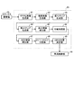
図1は、本実施形態に係る車両制御システムの概略構成を示す模式図である。車両制御システム1は、移動体である自動車等の自車両Mに搭載され、撮像部10と、画像解析部20と、車両制御部30とを備える。
FIG. 1 is a schematic diagram illustrating a schematic configuration of a vehicle control system according to the present embodiment. The
撮像部10は、自車両Mの前方領域を撮像領域として撮像する。撮像部10は、例えば、自車両MのフロントガラスFGのルームミラー(図示せず)付近に設置される。撮像部10の撮像によって得られる画像データは、画像解析部20に入力される。画像解析部20は、撮像部10から送信される画像データを解析して、自車両Mの前方に存在する人や他車両等の物体を検出する。画像解析部20の検出結果は、車両制御部30に出力される。
The
車両制御部30は、自車両Mに設けられた各種のセンサ(図示せず)から得られる車両情報に基づき、自車両Mの走行を支援するための制御を行う。車両情報は、例えば、車速や加速度、舵角、ヨーレート等を含む。また、車両制御部30は、画像解析部20から送信される検出結果に基づき、衝突を回避するための制御を行う。係る制御としては、例えば、自車両Mの運転者に物体の接近を報知する警告報知や、自動ブレーキ制御等が挙げられる。
The
図2は、撮像部10及び画像解析部20の概略構成を示す模式図である。撮像部10は、ステレオカメラであり、水平方向(左右方向)に設置された2台のカメラ11を有する。各カメラ11は、レンズ12、画像センサ13及び画像センサ制御部14を備える。
FIG. 2 is a schematic diagram illustrating a schematic configuration of the
画像センサ13は、CCDやCMOS等のイメージセンサである。画像センサ13は、レンズ12により結像される画像を画像データとして順次取得する。画像センサ制御部14は、画像解析部20(CPU21、FPGA22)からシリアルバスL1を介して入力される露光制御値等の各種指示データに基づき、画像センサ13の動作を制御する。また、画像センサ制御部14は、画像センサ13で取得された画像データを、データバスL2を介して、画像解析部20のRAM24に転送する。これにより、画像解析部20のRAM24には、視差情報を含む左右一対の画像データが順次記憶されることになる。
The
なお、後段の画像解析部20では、画像データに含まれる輝度信号に基づき画像の解析を行う。そこで、カメラ11の各々は、画像データとして輝度信号を画像解析部20に出力する構成としてもよい。また、画像センサ13がカラーイメージセンサの場合、例えば、画像センサ制御部14が、下記変換式(1)に基づいてRGB信号から輝度信号(Y)を取得することで、当該輝度信号を画像解析部20に出力する構成としてもよい。以下、輝度信号で構成される画像データを輝度画像という。
Y=0.3R+0.59G+0.11B … (1)
The subsequent
Y = 0.3R + 0.59G + 0.11B (1)
画像解析部20は、CPU21、FPGA22、ROM23、RAM24、シリアルIF25及びデータIF26等を備える。CPU21は、画像解析部20の動作を統括的に制御する。FPGA22は、RAM24に保存された画像データに対し所定の処理を施す。例えば、FPGA22は、ガンマ補正やゆがみ補正(左右画像の平行化)、後述する視差画像の生成等、リアルタイム性が要求される画像処理を実行する。また、カラーの画像データが撮像部10から入力される場合、FPGA22が、上記変換式(1)に基づいてRGB信号から輝度信号(輝度画像)を取得する構成としてもよい。
The
ROM23は、CPU21が実行可能な各種のプログラムや設定データを記憶する。例えば、ROM23は、後述するオブジェクトタイプテーブル等を記憶する。RAM24は、ワークエリアとして機能する。例えば、RAM24は、各種の画像データ(輝度画像、視差画像等)や、後述する第1Uマップ(第1マップに対応)、第2Uマップ(第2マップに対応)等を一時記憶する。
The
シリアルIF25及びデータIF26は、車両制御部30(図1参照)とCPU21との間のデータ授受を制御する。CPU21は、自車両Mの車両情報を、データIF26を介して車両制御部30から取得する。また、CPU21は、画像データから得られる各種の検出データを、シリアルIF25やデータIF26を介して、車両制御部30に出力する。
The serial IF 25 and the data IF 26 control data exchange between the vehicle control unit 30 (see FIG. 1) and the
次に、画像解析部20が備える機能構成について説明する。本実施形態において、画像解析部20は、物体検出装置として機能する。
Next, a functional configuration provided in the
図3は、画像解析部20の機能構成の一例を示す図である。図3に示すように、画像解析部20は、平行化画像生成部41、視差画像生成部42、第1Uマップ生成部43、第2Uマップ生成部44、孤立領域検出部45、分離処理部46、対応領域検出部47、オブジェクトタイプ分類部48及び3次元位置決定部49等を備える。なお、画像解析部20の各機能部は、CPU21とROM23に記憶されたプログラムとの協働により実現されるソフトウェア構成としてもよい。また、画像解析部20の各機能部は、FPGA22や専用のハードウェア等により実現されるハードウェア構成としてもよい。
FIG. 3 is a diagram illustrating an example of a functional configuration of the
平行化画像生成部41は、撮像部10から入力される左右一対の画像データ(輝度画像)毎に、平行化処理を実行する。平行化処理では、左右のカメラ11における光学系の歪みや相対的な位置関係に基づいて、各カメラ11から出力される左右一対の輝度画像を、平行化ステレオ画像となるように変換する。ここで、平行化ステレオ画像は、2つのピンホールカメラが平行に取り付けられたときに得られる理想的なステレオ画像を意味する。
The parallelized
なお、平行化処理の方法は特に問わず、公知の技術を用いることができる。例えば、平行化画像生成部41は、Δx=f(x、y)、Δy=g(x、y)という多項式を用いて各画素での歪み量を計算する。そして、平行化画像生成部41は、その計算結果を用いて、各カメラ11から出力される輝度画像の各画素を変換することで、平行化ステレオ画像を生成する。多項式は、例えば、x(画像の横方向位置)、y(画像の縦方向位置)に関する5次多項式に基づく。
Note that the parallelization method is not particularly limited, and a known technique can be used. For example, the parallelized
視差画像生成部42は、平行化理後の一対の輝度画像から左右の視差値を検出する。ここで視差値とは、輝度画像の一方を基準画像、他方を比較画像とし、撮像領域内の同一地点に対応した基準画像上の画像部分に対する比較画像上の画像部分の位置ズレ量を表すものである。
The parallax
例えば、視差画像生成部42は、基準画像の或る行について、一の注目画素を中心とした複数画素(例えば16画素×1画素)からなるブロックを定義する。一方、視差画像生成部42は、比較画像における同じ行において、定義した基準画像のブロックと同じサイズのブロックを1画素ずつ横ライン方向へずらす。また、視差画像生成部42は、基準画像で定義したブロックの画素値の特徴を示す特徴量と、比較画像における各ブロックの画素値の特徴を示す特徴量との相関を示す相関値を、それぞれ算出する。そして、視差画像生成部42は、算出した相関値に基づき、比較画像における各ブロックの中で最も基準画像のブロックと相関があった比較画像のブロックを選定するマッチング処理を行う。その後、視差画像生成部42は、基準画像のブロックの注目画素と、マッチング処理で選定された比較画像のブロックの対応画素との位置ズレ量を視差値dとして算出する。視差画像生成部42は、このような視差値dを算出する処理を基準画像の全域又は特定の一領域について行う。
For example, the parallax
マッチング処理に用いるブロックの特徴量としては、例えば、ブロック内の各画素の値(輝度値)を用いることができる。また、相関値としては、例えば、基準画像のブロック内の各画素の値(輝度値)と、これらの画素にそれぞれ対応する比較画像のブロック内の各画素の値(輝度値)との差分の絶対値の総和を用いることができる。この場合、総和値が最小となるブロックが、最も相関を有するものとなる。 As the feature amount of the block used for the matching process, for example, the value (luminance value) of each pixel in the block can be used. In addition, as the correlation value, for example, the difference between the value (luminance value) of each pixel in the block of the reference image and the value (luminance value) of each pixel in the block of the comparison image corresponding to each of these pixels. The sum of absolute values can be used. In this case, the block having the smallest sum value has the most correlation.
マッチング処理の方法は特に問わないものとする。例えばSSD(Sum of Squared Difference)、ZSSD(Zero-mean Sum of Squared Difference)、SAD(Sum of Absolute Difference)、ZSAD(Zero-mean Sum of Absolute Difference)等の方法を用いることができる。なお、マッチング処理では画素単位での視差値しか算出できないので、1画素未満のサブピクセルレベルの視差値が必要な場合には推定値を用いる必要がある。サブピクセルレベルの視差値を推定する推定方法としては、例えば、等角直線方式、二次曲線方式等を利用することができる。また、このサブピクセルレベルの推定視差値には誤差が発生するので、この推定誤差を減少させるEEC(推定誤差補正)等を用いてもよい。 The matching processing method is not particularly limited. For example, methods such as SSD (Sum of Squared Difference), ZSSD (Zero-mean Sum of Squared Difference), SAD (Sum of Absolute Difference), and ZSAD (Zero-mean Sum of Absolute Difference) can be used. In the matching process, only a parallax value in units of pixels can be calculated. Therefore, when a sub-pixel level parallax value less than one pixel is required, an estimated value needs to be used. As an estimation method for estimating a sub-pixel level parallax value, for example, an equiangular straight line method, a quadratic curve method, or the like can be used. In addition, since an error occurs in the estimated parallax value at the sub-pixel level, EEC (estimated error correction) or the like for reducing the estimated error may be used.
また、視差画像生成部42は、基準画像上の各画像部分(画素)について検出される視差値を、それぞれの画像部分の画素値として表した視差画像を生成する。ここで、視差画像を構成する各画素の画素位置は、点(u、v)で表される。なお、uは横座標、vは縦座標である。また、点(u、v)における画素の画素値は、d(u、v)で表され、該点(u、v)における視差値(視差情報)を表す。なお、視差画像の生成方法については、公知の技術を用いることが可能である。
Further, the parallax
第1Uマップ生成部43は、視差画像生成部42が生成した視差画像に基づき、視差画像の一軸方向での画素位置と、当該画素位置での視差値と、当該視差値が出現する視差頻度とを対応付けた第1Uマップを生成する。具体的に、第1Uマップ生成部43は、視差画像におけるu方向位置と、視差値dと、視差頻度とを、3次元の各軸方向に設定することで、2次元ヒストグラムを生成する。この2次元ヒストグラムを、第1Uマップと呼ぶ。なお、第1Uマップは、一般的にU−Disparityマップと呼ばれるデータに対応する。
The first U
第2Uマップ生成部44は、第1Uマップのu軸を、視差画像の画素単位から実際の距離の単位に変換した第2Uマップを生成する。画素単位から実距離の単位への変換方法は、特に問わないものとする。
The second U
ここで、図4〜図7を参照して、視差画像、第1Uマップ及び第2Uマップについて説明する。図4は、基準画像(輝度画像)の一例を模式的に示す図である。図5は、図4の基準画像に対応する視差画像を模式的に示す図である。この視差画像では、基準画像の横軸がu方向位置に対応し、基準画像の縦軸がv方向位置に対応する。図6は、図5の視差画像に対応する第1Uマップを模式的に示す図である。この第1Uマップでは、横軸が視差画像におけるu方向位置に対応し、縦軸が視差値dに対応する。また、図7は、図6の第1Uマップに対応する第2Uマップを模式的に示す図である。この第2Uマップでは、横軸が視差画像におけるu方向位置を実距離に変換した位置ruに対応し、縦軸が視差値dに対応する。なお、図6、図7の縦軸では、下方に向かうほど視差値dが大きくなる。 Here, the parallax image, the first U map, and the second U map will be described with reference to FIGS. FIG. 4 is a diagram schematically illustrating an example of a reference image (luminance image). FIG. 5 is a diagram schematically illustrating a parallax image corresponding to the reference image in FIG. 4. In this parallax image, the horizontal axis of the reference image corresponds to the u-direction position, and the vertical axis of the reference image corresponds to the v-direction position. FIG. 6 is a diagram schematically illustrating a first U map corresponding to the parallax image in FIG. 5. In the first U map, the horizontal axis corresponds to the u-direction position in the parallax image, and the vertical axis corresponds to the parallax value d. FIG. 7 is a diagram schematically showing a second U map corresponding to the first U map of FIG. In the second U map, the horizontal axis corresponds to the position ru obtained by converting the u-direction position in the parallax image into the actual distance, and the vertical axis corresponds to the parallax value d. 6 and 7, the parallax value d increases as it goes downward.
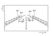
図4に示す画像例では、路面の左右両側にガードレールA11、A12が存在する。また、ガードレールA11、A12の間に、他車両として、先行車両A13と対向車両A14とがそれぞれ1台ずつ存在する。また、図4の基準画像と図示しない比較画像との関係から、図5に示す視差画像が得られる。この視差画像では、画素群B11、画素群B12が、基準画像でのガードレールA11、A12に対応する。また、画素群B13が、基準画像での先行車両A13に対応し、画素群B14が、基準画像での対向車両A14に対応する。なお、視差画像では、視差値dは画素値として表される。 In the image example shown in FIG. 4, guard rails A11 and A12 exist on both the left and right sides of the road surface. In addition, there is one preceding vehicle A13 and one oncoming vehicle A14 as other vehicles between the guard rails A11 and A12. Moreover, the parallax image shown in FIG. 5 is obtained from the relationship between the reference image shown in FIG. 4 and a comparison image (not shown). In this parallax image, the pixel group B11 and the pixel group B12 correspond to the guard rails A11 and A12 in the reference image. The pixel group B13 corresponds to the preceding vehicle A13 in the reference image, and the pixel group B14 corresponds to the oncoming vehicle A14 in the reference image. In the parallax image, the parallax value d is expressed as a pixel value.
また、第1Uマップでは、図6に示すように、ガードレールA11、A12(画素群B11、B12)、に対応する高頻度の画素群C11、C12が、左右両端部から中央に向かって延びるような略直線状に分布する。また、先行車両A13(画素群B13)及び対向車両A14(画素群B14)に対応する高頻度の画素群C13、C14は、画素群C11と画素群C12との間で、略u軸方向に平行に延びる線分の状態で分布する。なお、先行車両A13の背面部分又は対向車両A14の前面部分以外に、これらの車両の側面部分が映し出されているような状況にあっては、同じ他車両を映し出している画像領域内において視差が生じる。このような場合、図6に示すように、他車両に対応する高頻度の画素群は、略u軸方向に延びる線分と略u軸方向に対して傾斜した線分とが連結した状態の分布を示す。 Further, in the first U map, as shown in FIG. 6, the high-frequency pixel groups C11 and C12 corresponding to the guard rails A11 and A12 (pixel groups B11 and B12) extend from the left and right ends toward the center. Distributed in a substantially straight line. The high-frequency pixel groups C13 and C14 corresponding to the preceding vehicle A13 (pixel group B13) and the oncoming vehicle A14 (pixel group B14) are substantially parallel to the u-axis direction between the pixel group C11 and the pixel group C12. It is distributed in the state of a line segment extending to. In addition, in situations where the side portions of these vehicles other than the rear portion of the preceding vehicle A13 or the front portion of the oncoming vehicle A14 are projected, the parallax is within the image area displaying the same other vehicle. Arise. In such a case, as shown in FIG. 6, the high-frequency pixel group corresponding to the other vehicle has a state in which a line segment extending in the substantially u-axis direction and a line segment inclined with respect to the substantially u-axis direction are connected. Show the distribution.
また、図6の第1Uマップから生成される第2Uマップは、図7のように表される。この第2Uマップでは、被写体との距離に応じて視差値dを間引きした、間引き視差という単位を縦軸に用いた例を示している。なお、視差値dの間引き量は、近距離に存在する物体ほど大きくすることが好ましい。近距離の場合は物体が大きく写るため、視差情報(視差値dの個数)が多く距離の分解能も大きいので大きく間引くことができる。 Moreover, the 2nd U map produced | generated from the 1st U map of FIG. 6 is represented like FIG. In the second U map, an example is shown in which the unit of thinning parallax, in which the parallax value d is thinned out according to the distance to the subject, is used on the vertical axis. It should be noted that the thinning amount of the parallax value d is preferably increased as the object is present at a short distance. In the case of a short distance, an object appears large, so that the amount of parallax information (number of parallax values d) is large and the resolution of the distance is large, so that thinning can be performed greatly.
図7の第2Uマップにおいて、ガードレールA11、A12(画素群C11、C12)に対応する高頻度の画素群D11、D12は、左右両端部において垂直に延びるような略直線状に分布する。また、先行車両A13(画素群C13)及び対向車両A14(画素群C14)に対応する高頻度の画素群D13、D14は、画素群D11と画素群D12との間で、略L字状の線分の状態で分布する。ここで、略L字状を構成する線分のうち、ru軸方向の線分は、先行車両A13の背面部分又は対向車両A14の前面部分に対応する。また、略L字状を構成する線分のうち、d軸方向の線分は、先行車両A13及び対向車両A14の側面部分に対応する。 In the second U map of FIG. 7, the high-frequency pixel groups D11 and D12 corresponding to the guard rails A11 and A12 (pixel groups C11 and C12) are distributed in a substantially straight line extending vertically at the left and right ends. The high-frequency pixel groups D13 and D14 corresponding to the preceding vehicle A13 (pixel group C13) and the oncoming vehicle A14 (pixel group C14) are substantially L-shaped lines between the pixel group D11 and the pixel group D12. Distributed in minutes. Here, among the line segments that form a substantially L shape, the line segment in the ru-axis direction corresponds to the back surface portion of the preceding vehicle A13 or the front surface portion of the oncoming vehicle A14. Of the line segments that form a substantially L shape, the line segment in the d-axis direction corresponds to the side surface portions of the preceding vehicle A13 and the oncoming vehicle A14.
図3に戻り、孤立領域検出部45は、第2Uマップ上において、視差頻度が周囲より高い領域を孤立領域として検出する。具体的に、孤立領域検出部45は、視差頻度が所定値(閾値)以上の一の画素(以下、有効画素という)について、当該有効画素を中心とする8近傍に他の有効画素が存在するか否かを判定する。ここで、有効画素か否かを判別するための閾値は特に問わないものとするが、孤立領域の検出結果等に基づき、孤立領域の検出を適正に行うことが可能な値を採用することが好ましい。例えば、閾値は、撮像領域の環境や、物体を測定する測定モード等の条件に応じて切り替える構成してもよい。なお、有効画素は、図7で示した画素群D13等を構成する各画素に対応するものである。
Returning to FIG. 3, the isolated
他の有効画素が8近傍に存在する場合、孤立領域検出部45は、中心の有効画素と他の有効画素とが連結した画素群と判断する。また、孤立領域検出部45は、第2Uマップ上の各有効画素について上記処理を実行することで、各有効画素を一又は複数の画素群にグルーピングする。そして、孤立領域検出部45は、各画素群に外接する矩形状の領域を孤立領域としてそれぞれ検出する。
When other effective pixels exist in the vicinity of 8, the isolated
ここで、図8、図9を参照して、孤立領域検出部45の動作について説明する。図8、図9は、孤立領域検出部45の動作を説明するための図であり、有色で表した各画素は、第2Uマップ上での有効画素を示している。
Here, the operation of the isolated
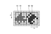
例えば、図8の場合、孤立領域検出部45は、上記した8近傍のルールに基づき、複数の有効画素を、画素群D1と画素群D2とにそれぞれグルーピングする。そして、孤立領域検出部45は、画素群D1、D2にそれぞれ外接する矩形状の領域を、孤立領域E1、E2としてそれぞれ検出する。また、図9の場合、孤立領域検出部45は、上記した8近傍のルールに基づき、複数の有効画素を、一の画素群D3にグルーピングする。そして、孤立領域検出部45は、画素群D3に外接する矩形状の領域を孤立領域E3として検出する。
For example, in the case of FIG. 8, the isolated
なお、孤立領域検出部45は、孤立領域の検出に先駆けて、第2Uマップに含まれるノイズの除去や、孤立領域の検出を容易化するための処理を施してもよい。例えば、孤立領域検出部45は、平滑化フィルタ等を用いることで第2Uマップを平滑化する処理を施してもよい。また、孤立領域検出部45は、閾値の値に基づいて第2Uマップに二値化処理を施してもよい。また、グルーピング後の画素群の大きさ(幅や高さ、画素数等)が所定値以下のものを、検出対象から除外する構成としてもよい。
Note that the isolated
ところで、撮像領域内において複数の物体(オブジェクト)が並んで存在するような場合、図9に示したように、各の物体に対応する画素群(有効画素)が接続された状態で表されることがある。 By the way, when a plurality of objects (objects) exist side by side in the imaging region, as shown in FIG. 9, the pixel groups (effective pixels) corresponding to the respective objects are connected. Sometimes.
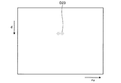
例えば、図10に示すように、道路の中央で人A21、A22が並んでいる状態を撮像した基準画像からは、図11に示すように、人A21、A22に対応する画素群D23が表された第2Uマップが得られる。ここで、図10は、基準画像の他の例を模式的に示す図である。また、図11は、図10の基準画像に対応する第2Uマップを模式的に示す図である。 For example, as illustrated in FIG. 10, a pixel group D23 corresponding to the people A21 and A22 is represented from the reference image obtained by imaging the state where the people A21 and A22 are arranged in the center of the road as illustrated in FIG. 11. A second U map is obtained. Here, FIG. 10 is a diagram schematically illustrating another example of the reference image. FIG. 11 is a diagram schematically showing a second U map corresponding to the reference image of FIG.
図10では人A21と人A22とが密接して並んでいるため、当該人A21、A22に対応する第2Uマップ上での有効画素は、一塊の画素群D23として表される。この場合、孤立領域検出部45は、図12に示すように、画素群D23を一塊の画素群としてグルーピングする。また、孤立領域検出部45は、画素群D23に外接する矩形状の領域を孤立領域E23として検出する。なお、図12は、図11で示した画素群D23部分の拡大図であり、画素の濃度が濃くなるほど視差頻度が高いことを示している。
In FIG. 10, since the person A21 and the person A22 are closely arranged, the effective pixels on the second U map corresponding to the persons A21 and A22 are represented as a lump pixel group D23. In this case, as illustrated in FIG. 12, the isolated
このように、複数の物体が隣接して存在するような場合、孤立領域検出部45では、個々の物体の孤立領域を検出できない可能性がある。また、個々の物体の孤立領域を検出することができない場合、孤立領域を大きく見積もることになるため、物体の本来の大きさを特定することができず、物体の識別精度が低下することなる。
Thus, when there are a plurality of objects adjacent to each other, the isolated
そこで、本実施形態の分離処理部46では、複数の物体分の画素群で構成される一の孤立領域を、物体毎の孤立領域に分割するための処理を実行する。以下、分離処理部46について説明する。
Therefore, the
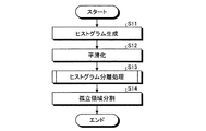
図13は、分離処理部46の構成の一例を示す図である。図13に示すように、分離処理部46は、ヒストグラム生成部461、ヒストグラム平滑化部462及びヒストグラム分離部463等の機能部を備える。また、分離処理部46は、各機能部と協働して図14に示す処理を実行することで、孤立領域検出部45で検出された孤立領域を、物体毎の孤立領域に分割する。ここで、図14は、分離処理部46が行う処理の流れを示すフローチャートである。
FIG. 13 is a diagram illustrating an example of the configuration of the
まず、ヒストグラム生成部461は、分離処理部46で検出された孤立領域毎に、視差頻度の分布を示すヒストグラムを、視差頻度分布情報として生成する(ステップS11)。具体的に、ヒストグラム生成部461は、孤立領域に含まれる各画素(有効画素)の視差頻度に基づき、当該孤立領域の横軸方向の各位置(ru)をビンとしたヒストグラムを生成する。ここで、ヒストグラムの生成方法は特に問わないものとする。例えば、ヒストグラム生成部461は、孤立領域の縦軸(d軸)方向について視差頻度を積算することで、各位置ruをビンとしたヒストグラムを生成する。また、他の生成方法としては、ヒストグラム生成部461は、孤立領域の縦軸(d軸)方向について視差頻度の中央値をとることで、各位置ruをビンとしたヒストグラムを生成する。なお、本実施形態では、視差頻度を積算する前者の生成方法を用いるものとする。
First, the
ヒストグラム平滑化部462は、ヒストグラム生成部461が生成したヒストグラムを平滑化する処理を施す(ステップS12)。ここで、平滑化は公知の技術を用いるものとする。なお、ヒストグラム平滑化部462は、ヒストグラムの全体を一度に平滑化する構成としてもよい。また、後述するヒストグラム分離処理において処理対象のビンが選択される毎に、周辺のビンの視差頻度に基づき処理対象のビンを平滑化する構成としてもよい。
The
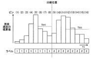
例えば、図12に示した孤立領域E23についてヒストグラムを生成すると、その結果は図15に示すものとなる。図15は、ヒストグラムの一例を示す図であり、ヒストグラム平滑化部462による平滑化後の状態を示している。また、横軸は孤立領域での横軸方向位置(ru)に対応し、縦軸は視差頻度の積算値に対応する。
For example, when a histogram is generated for the isolated region E23 shown in FIG. 12, the result is shown in FIG. FIG. 15 is a diagram illustrating an example of a histogram, and illustrates a state after smoothing by the
図14に戻り、ヒストグラム分離部463は、ヒストグラム平滑化部462で平滑化されたヒストグラムに対し、孤立領域を分離するための処理を施す(ステップS13)。以下、ヒストグラム分離部463がステップS13で行う処理について説明する。
Returning to FIG. 14, the
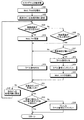
図16は、ヒストグラム分離部463が実行する処理の流れを示すフローチャートである。まず、ヒストグラム分離部463は、ヒストグラムを分割する際の指標値となる、最大値MAX及び第1閾値TH1の値を0に初期化する(ステップS21)。次いで、ヒストグラム分離部463は、位置ruが最小のビン(ヒストグラム)を最初の処理対象に設定する(ステップS22)。
FIG. 16 is a flowchart showing a flow of processing executed by the
続いて、ヒストグラム分離部463は、処理対象のビンの視差頻度(積算値)が最大値MAXを上回るか否かを判定する(ステップS23)。視差頻度が最大値MAXを上回る場合(ステップS23;Yes)、ヒストグラム分離部463は、その視差頻度に基づき、最大値MAX及び第1閾値TH1を更新する(ステップS24)。具体的に、ヒストグラム分離部463は、最大値MAXを視差頻度の値に更新する。また、ヒストグラム分離部463は、更新後の最大値MAXに所定の比率αを乗算することで、新たな第1閾値TH1を算出する。
Subsequently, the
ここで、比率αの値は特に問わず、例えば0.8等の任意の値を設定することができる。なお、比率αの値は、孤立領域の分離結果等に基づき、適正な分離を行うことが可能な値を採用することが好ましい。また、比率αの値は、撮像領域の環境や各種の条件に応じて切り替える構成としてもよい。 Here, the value of the ratio α is not particularly limited, and an arbitrary value such as 0.8 can be set. The value of the ratio α is preferably a value that enables proper separation based on the separation result of the isolated region. In addition, the value of the ratio α may be switched according to the environment of the imaging region and various conditions.
次いで、ヒストグラム分離部463は、処理対象のビンにラベル番号を付与し(ステップS25)、ステップS31に移行する。ここで、付与されるラベル番号は、例えば“1”であり、後述するステップS31でインクリメントが行われるまで、同一のラベル番号が付与されるものとする(ステップS28も同様)。
Next, the
一方、ステップS23において、視差頻度が最大値MAX以下と判定した場合(ステップS23;No)、ヒストグラム分離部463は、当該視差頻度が第1閾値TH1を上回るか否かを判定する(ステップS26)。視差頻度が第1閾値TH1を上回る場合(ステップS26;Yes)、ヒストグラム分離部463は、ステップS25に移行することでラベル番号の付与を行う。また、視差頻度が第1閾値TH1以下の場合(ステップS26;No)、ヒストグラム分離部463は、処理対象のビンに隣接する他のビンの視差頻度と比較し、処理対象のビンの視差頻度が最小か否かを判定する(ステップS27)。
On the other hand, when it is determined in step S23 that the parallax frequency is equal to or less than the maximum value MAX (step S23; No), the
ステップS27において、視差頻度が最小とならない場合(ステップS27;No)、ヒストグラム分離部463は、ステップS25に移行することでラベル番号の付与を行う。また、視差頻度が最小となった場合(ステップS27;Yes)、ヒストグラム分離部463は、処理対象のビンにラベル番号を付与した後(ステップS28)、そのラベル番号をインクリメントする(ステップS29)。次いで、ヒストグラム分離部463は、最大値MAX及び第1閾値TH1の値を0に初期化した後(ステップS30)、ステップS31に移行する。
In step S27, when the parallax frequency is not minimized (step S27; No), the
続くステップS31において、ヒストグラム分離部463は、末尾のビンまで処理したか否かを判定する(ステップS31)。未処理のビンが存在する場合(ステップS31;No)、ヒストグラム分離部463は、次のビンを処理対象に設定した後(ステップS32)、ステップS23に戻る。また、末尾のビンまで処理した場合(ステップS31;Yes)、ヒストグラム分離部463は、次のステップS33に移行する。
In subsequent step S31, the
ここで、図15のヒストグラムを参照して、ステップS21〜S31の処理について説明する。なお、図15では、左端のビンを位置ruが最小のビンとして説明を進めるが、第2Uマップ内での孤立領域の配置位置等に応じて、右端のビンを位置ruが最小のビンとしてもよい。 Here, the processing of steps S21 to S31 will be described with reference to the histogram of FIG. In FIG. 15, the description is made with the leftmost bin as the bin with the smallest position ru. However, depending on the position of the isolated region in the second U map, the rightmost bin may be designated as the bin with the smallest position ru. Good.
ヒストグラム分離部463は、左端のビン(1)から右端のビン(16)にかけてステップS21〜S31の処理を順次実行する。ここで、ビン(1)からビン(5)にかけては視差頻度が増加するため、ヒストグラム分離部463は、最大値MAX及び第1閾値TH1を順次更新する。また、視差頻度はビン(5)でピークを迎えるため、ヒストグラム分離部463は、ビン(5)以降、最大値MAX及び第1閾値TH1の更新を停止する。そして、ヒストグラム分離部463は、ビン(8)で視差頻度の最小値(谷)を検出するまで、ビン(1)からビン(8)にかけて、同一のラベル番号“1”を順次付与する。
The
続いて、ヒストグラム分離部463は、ラベル番号を“2”にインクリメントし、最大値MAX及び第1閾値TH1を初期化する。続くビン(9)からビン(11)にかけて視差頻度が増加するため、ヒストグラム分離部463は、最大値MAX及び第1閾値TH1を順次更新する。また、視差頻度はビン(11)でピークを迎えるため、ヒストグラム分離部463は、ビン(11)以降、最大値MAX及び第1閾値TH1の更新を停止する。そして、ヒストグラム分離部463は、ビン(16)で視差頻度の最小値(谷)を検出するまで、ビン(9)から末尾のビン(16)にかけて、同一のラベル番号“2”を順次付与する。
Subsequently, the
上記の処理により同一のラベル番号が付与されたビンのグループは、ヒストグラムの山を形成する。例えば、ヒストグラム分離部463は、図15のヒストグラムについて、ビン(1)〜ビン(8)の山と、ビン(9)〜ビン(16)の山とを検出する。
The bin groups to which the same label numbers are assigned by the above processing form a histogram peak. For example, the
図16に戻り、ヒストグラム分離部463は、続くステップS33において、最後に検出された山(ヒストグラム)の最大値が、予め定められた第2閾値TH2を上回っているか否かを判定する(ステップS33)。第2閾値TH2を上回っていると判定した場合(ステップS33;Yes)、ヒストグラム分離部463は本処理を終了し、図14のステップS14に移行する。また、第2閾値TH2以下と判定した場合(ステップS33;No)、ヒストグラム分離部463は、最後の山の各ビンに付与したラベル番号をデクリメントし(ステップS34)、図14のステップS14に移行する。
Returning to FIG. 16, in the subsequent step S33, the
ここで、図17を参照して、ステップS33、S34の処理について説明する。図17は、ヒストグラムの他の例を示す図である。図17に示すように、視差頻度の最小値(ビン(14))が出現した直後に小規模な山(ビン(15)、(16))が出現する場合がある。この場合、ヒストグラム分離部463は、上記したステップS21〜S31の処理により、ビン(15)及びビン(16)に対し、他のグループとは異なるラベル番号“3”を付与することになる。
Here, with reference to FIG. 17, the process of step S33, S34 is demonstrated. FIG. 17 is a diagram illustrating another example of a histogram. As shown in FIG. 17, a small mountain (bin (15), (16)) may appear immediately after the minimum value of the parallax frequency (bin (14)) appears. In this case, the
しかしながら、図17のヒストグラムの場合、ラベル番号“3”が付与されたグループは独立したグループでなく、ラベル番号“2”が付与された直前のグループの一部と考えることが適正である。そこで、ヒストグラム分離部463は、最後のグループの山の最大値(ピーク値)が第2閾値TH2以下となる場合、直前のグループに付与したラベル番号に振りなおすことで、グループ分けの誤りを訂正する。これにより、孤立領域が不用意に分割されてしまうことを防ぐことができるため、孤立領域の大きさをより適切に見積もることができる。
However, in the case of the histogram of FIG. 17, it is appropriate to consider that the group assigned the label number “3” is not an independent group but a part of the group immediately before the label number “2”. Therefore, when the maximum value (peak value) of the peak of the last group is equal to or less than the second threshold value TH2, the
なお、第2閾値TH2の値は特に問わないものとする。例えば、第2閾値TH2は、固定値としてもよいし、直前のグループの最大値MAXに所定の比率βを乗算することで導出してもよい(但しα>β)。また、第2閾値TH2や比率βの値は、孤立領域の分離結果等に基づき、適正な分離を行うことが可能な値を採用することが好ましい。また、第2閾値TH2や比率βの値は、撮像領域の環境や各種の条件に応じて切り替える構成してもよい。また、本実施形態では、末尾のグループにステップS33、S34の処理を施す構成としたが、これに限らず、新たなグループ(ヒストグラムの山)を検出する度に、当該グループに処理を施す構成としてもよい。 Note that the value of the second threshold TH2 is not particularly limited. For example, the second threshold value TH2 may be a fixed value or may be derived by multiplying the maximum value MAX of the immediately preceding group by a predetermined ratio β (where α> β). In addition, it is preferable that values for the second threshold value TH2 and the ratio β are values that allow appropriate separation based on the separation result of the isolated region. Further, the second threshold value TH2 and the value of the ratio β may be switched according to the environment of the imaging region and various conditions. In the present embodiment, the process of steps S33 and S34 is performed on the last group. However, the present invention is not limited to this, and a process is performed on the group every time a new group (histogram peak) is detected. It is good.
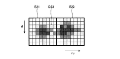
図14に戻り、分離処理部46は、ステップS13で各孤立領域のヒストグラムに付与されたラベル番号に基づき、孤立領域を分割するための処理を行う(ステップS14)。例えば、図12の孤立領域E23は、図15のヒストグラムに付与されたラベル番号に基づき、図18に示すように、ビン(8)、(9)間を分離位置とした二つの孤立領域E21とE22とに分割される。なお、全てのヒストグラム(ビン)に同一のラベル番号が付された孤立領域については、分割の対象外となる。
Returning to FIG. 14, the
ここで、孤立領域の幅(第2Uマップ上でのU軸方向長さ)は、その孤立領域が表す物体の幅に対応する。また、矩形領域の高さは、その孤立領域が表す物体の奥行きに対応する。一方、物体の高さについては、この段階では不明である。 Here, the width of the isolated region (the length in the U-axis direction on the second U map) corresponds to the width of the object represented by the isolated region. The height of the rectangular area corresponds to the depth of the object represented by the isolated area. On the other hand, the height of the object is unknown at this stage.
そこで、対応領域検出部47は、物体の高さを得るため、孤立領域に対応する視差画像上での対応領域を検出する。なお、分離処理部46で複数の孤立領域に分割された場合、対応領域検出部47は、分割後の各孤立領域について対応領域の検出を行うものとする。
Therefore, the corresponding
図19は、対応領域検出部47の動作を説明するための図であり、図5に示した視差画像に対応する。まず、対応領域検出部47は、第2Uマップ上での孤立領域の幅、すなわちru軸方向座標がruminからrumaxまでの範囲に対応する検出幅W1、W2について、視差画像のv軸方向に走査する。次いで、対応領域検出部47は、第2Uマップ上での孤立領域の高さ、すなわちd軸方向の座標がdminからdmaxまでの範囲の値を視差値dとする画素を、上記検出幅の中から候補画素として抽出する。
FIG. 19 is a diagram for explaining the operation of the corresponding
対応領域検出部47は、このようにして抽出した候補画素群の中で、検出幅W1、W2に対して所定の数以上の候補画素が存在する横方向のラインを、オブジェクト候補ラインとして決定する。次に、対応領域検出部47は、視差画像をV軸方向に走査して、ある注目しているオブジェクト候補ラインの周囲に他のオブジェクト候補ラインが所定の密度以上で存在している場合、その注目しているオブジェクト候補ラインをオブジェクトラインとして判定する。
The corresponding
対応領域検出部47は、各孤立領域に対応する各検出幅について、オブジェクトラインを探索する。そして、対応領域検出部47は、各孤立領域について検出したオブジェクトライン群の外接矩形を、当該孤立領域に対応する視差画像上での領域(オブジェクト領域)F13、F14として決定する。
The corresponding
オブジェクトタイプ分類部48は、対応領域検出部47で検出されたオブジェクト領域の特性に基づき、このオブジェクト領域に表された物体の種別(オブジェクトタイプ)を分類する。
The object
具体的に、オブジェクトタイプ分類部48は、下記式(1)に基づき、オブジェクト領域の高さ(yomax−yomin)から、そのオブジェクト領域に表された物体の高さHoを算出する。ここで、「zo」は、オブジェクト領域内での最小視差値dminから計算される、当該オブジェクト領域に対応するオブジェクトと自車両との間の距離である。また、「f」はカメラの焦点距離である。
Ho=zo×(yomax−yomin)/f …(1)
Specifically, the object
Ho = zo × (yomax−yomin) / f (1)
また、オブジェクトタイプ分類部48は、下記式(2)に基づき、オブジェクト領域の幅(xomax−xomin)から、そのオブジェクト領域に表された物体の幅Woを算出する。
Wo=zo×(xomax−xomin)/f …(2)
Further, the object
Wo = zo × (xomax−xomin) / f (2)
さらに、オブジェクトタイプ分類部48は、下記の式(3)に基づき、オブジェクト領域内での最大視差値dmaxと最小視差値dminとから、そのオブジェクト領域に表された物体の奥行きDoを算出する。ここで、「offset」は無限遠の物体を撮影したときの視差値である。
Do=BF×(1/(dmin−offset)−1/(dmax−offset)) …(3)
Further, the object
Do = BF × (1 / (dmin−offset) −1 / (dmax−offset)) (3)
オブジェクトタイプ分類部48は、オブジェクト領域(孤立領域)の各々について、その領域に表された物体の種別を分類(特定)する。具体的に、オブジェクトタイプ分類部48は、各オブジェクト領域の幅Wo、高さHo、奥行きDoを特徴量として取得すると、予め用意した各オブジェクトタイプの特徴量と比較することで該当するオブジェクトタイプを特定する。ここで、オブジェクトタイプとしては、例えば、歩行者(子供)や歩行者(大人)、オートバイや自転車、普通自動車や大型自動車等が挙げられる。これらオブジェクトタイプの特徴量(幅Wo、高さHo、奥行きDo)は、例えば、テーブル(オブジェクトタイプテーブル)等のデータ形式でROM23に記憶される。
The object
3次元位置決定部49は、対応領域検出部47で検出された各オブジェクト領域に対応する物体の3次元位置を特定する。ここで、3次元位置は、実空間上での存在位置を意味する。本実施形態では、カメラ11に対する相対的な横方向位置Xo及び高さ方向位置Yoを、3次元位置とする。
The three-dimensional
具体的に、3次元位置決定部49は、視差画像上における画像中心座標(i_centerX,i_centerY)と、各オブジェクト領域の中心座標(r_centerX,r_centerY)とを取得する。そして、3次元位置決定部49は、下記式(4)及び式(5)に基づき、撮像部10(ステレオカメラ)に対する相対的な横方向位置Xo及び高さ方向位置Yoを算出する。なお、「Z」は、視差値dから計算される距離(z=BF/(d−offset))である。ここで、「BF」は、撮像部10の基線長と焦点距離を乗じた値であり、「offset」は無限遠の物体を撮影したときの視差値である。また、「f」は撮像部10の焦点距離である。
Xo=Z×(r_centerX−i_centerX)/f …(4)
Yo=Z×(r_centerY−i_centerY)/f …(5)
Specifically, the three-dimensional
Xo = Z × (r_centerX−i_centerX) / f (4)
Yo = Z × (r_centerY−i_centerY) / f (5)
画像解析部20は、オブジェクト領域の各々について、オブジェクトタイプ分類部48及び3次元位置決定部49で取得されたオブジェクトタイプと3次元位置とを組とし、車両制御部30に出力する。
The
そして、車両制御部30では、画像解析部20から入力されるオブジェクトタイプと3次元位置との組に基づき衝突回避制御を行う。例えば、車両制御部30は、図示しない表示装置や音声出力装置を介して、物体のオブジェクトタイプや自車両Mとの位置関係を運転者に報知する。また、例えば、車両制御部30は、物体との衝突が予測される場合、ブレーキを掛けることで自車両Mを減速させる。
The
以上のように、本実施形態によれば、孤立領域検出部45で検出された孤立領域を、当該孤立領域を構成する各画素の視差頻度に基づいて分割する。これにより、物体の大きさをより適切に見積もることができるため、物体の検出精度を向上させることができる。また、本実施形態によれば、物体の大きさが適切に見積もられた孤立領域に基づき、オブジェクトタイプを分類することができるため、オブジェクトタイプの分類精度を向上させることができる。
As described above, according to the present embodiment, the isolated area detected by the isolated
[変形例1]
次に、上記実施形態の変形例(変形例1)について説明する。上記実施形態では、孤立領域を検出するため、第1Uマップの横軸を実際の距離の単位に変換した第2Uマップを生成する構成を説明した。しかしながら、この第1Uマップから第2Uマップへの変換では、物体を表す画素領域の形状が変形することが知られている。係る変形は、特に遠方で且つ画角端で顕著となる。
[Modification 1]
Next, a modified example (modified example 1) of the above embodiment will be described. In the above embodiment, a configuration has been described in which a second U map is generated by converting the horizontal axis of the first U map into an actual distance unit in order to detect an isolated region. However, it is known that in the conversion from the first U map to the second U map, the shape of the pixel region representing the object is deformed. Such deformation is particularly noticeable at a far distance and at the angle of view.
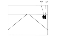
例えば、図20のように、遠方で且つ画角端に存在する人A31、A32を撮像した場合、この基準画像に基づき生成される第2Uマップは図21のようになる。ここで、図20は、基準画像の他の例を模式的に示す図である。また、図21は、図20の基準画像に対応する第2Uマップを模式的に示す図である。なお、図20は、図10に示した場面(場所)と同様である。 For example, as shown in FIG. 20, when a person A31, A32 present at a far field angle end is imaged, the second U map generated based on this reference image is as shown in FIG. Here, FIG. 20 is a diagram schematically illustrating another example of the reference image. FIG. 21 is a diagram schematically showing a second U map corresponding to the reference image of FIG. FIG. 20 is the same as the scene (location) shown in FIG.
図20の状態の場合、人A31と人A32とが密接して並んでいるため、当該人A31、A32に対応する第2Uマップ上での有効画素は、一塊の画素群D33として表される。ここで、道路の中央に存在する人A21、A22を撮像した基準画像から得られる画素群D23(図11参照)と、図21の画素群D33とを比較すると、画素群D33の形状は画素群D23の形状と比較し傾斜(変形)していることが分かる。 In the case of the state of FIG. 20, since the person A31 and the person A32 are closely arranged, the effective pixels on the second U map corresponding to the persons A31 and A32 are represented as a group of pixels D33. Here, when the pixel group D23 (see FIG. 11) obtained from the reference image obtained by capturing the people A21 and A22 existing in the center of the road is compared with the pixel group D33 in FIG. 21, the shape of the pixel group D33 is the pixel group. It can be seen that it is inclined (deformed) compared to the shape of D23.
また、図21の場合、孤立領域検出部45は、図22に示すように、傾斜した画素群D33を一塊の画素群としてグルーピングし、この画素群D33に外接する矩形状の領域を孤立領域E33として検出する。なお、図22は、図21で示した画素群D33部分の拡大図であり、画素の濃度が濃くなるほど視差頻度が高いことを示している。
In the case of FIG. 21, the isolated
このように、孤立領域内の画素群に変形が生じている場合、ヒストグラム生成部461が生成するヒストグラムも影響を受けることになる。例えば、図22の孤立領域E33についてヒストグラムを生成すると、ヒストグラム生成部461は、孤立領域E33の縦軸方向について視差頻度の加算等を行う。このとき、ヒストグラム生成部461は、孤立領域E33の中央部周辺において、異なる物体に係る視差頻度を混合することになるため、物体間の境界は不鮮明となる。このように生成されたヒストグラムでは、個々の物体について孤立領域を分離することが困難となる可能性がある。
As described above, when the pixel group in the isolated region is deformed, the histogram generated by the
そこで、変形例1では、孤立領域(画素群)に生じた変形を補正することで、孤立領域の分離を容易に行うことが可能な構成について説明する。以下、本変形例に係る分離処理部46Aの構成について説明する。分離処理部46Aは、上記実施形態の分離処理部46に対応するものである。なお、上記実施形態と同様の構成については、同一の符号を付与し説明を省略する。
In the first modification, a configuration in which the isolated area can be easily separated by correcting the deformation generated in the isolated area (pixel group) will be described. Hereinafter, the configuration of the
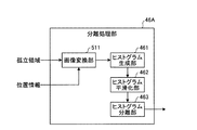
図23は、変形例1に係る分離処理部46Aの構成を模式的に示す図である。図23に示すように、分離処理部46Aは、画像変換部511、ヒストグラム生成部461、ヒストグラム平滑化部462及びヒストグラム分離部463等の機能部を備える。
FIG. 23 is a diagram schematically illustrating the configuration of the
画像変換部511には、孤立領域検出部45で検出された孤立領域と、各孤立領域の位置情報(画素位置、座標等)とが入力される。なお、位置情報は、孤立領域検出部45から入力される構成としてもよいし、CPU21から入力される構成としてもよい。画像変換部511は、孤立領域の各々について、当該孤立領域内で画素位置を変換し、変換後の孤立領域をヒストグラム生成部461に出力する。以下図24を参照しながら、画像変換部511の動作について説明する。
The
図24は、画像変換部511の動作を説明するための図である。ここで、図24は、第2Uマップを表しており、横軸が位置ruに対応し、縦軸が視差値dに対応する。また、図24中に示す孤立領域は、図22に示した孤立領域E33に対応する。なお、第2Uマップの中央を走る縦軸方向の破線は、撮像部10のカメラ位置(カメラ中心)を示している。
FIG. 24 is a diagram for explaining the operation of the
まず、画像変換部511は、孤立領域E33内において、変換処理の基準となる基準位置(視差値d)を設定する。ここで、基準位置は、特に問わないものとするが、図24に示すように、孤立領域E33の中心位置に対応する視差値dとすることが好ましい。
First, the
次いで、画像変換部511は、孤立領域E33を構成する各画素の横軸方向の画素位置xorg(単位:ピクセル)を、下記式(6)に基づき、新たな画素位置xnew(単位:ピクセル)に変換する。ここで、dist1は、基準位置と撮像部10(自車両M)との間の距離(単位:mm)である。また、dist2は、処理対象の画素と撮像部10(自車両M)との間の距離(単位:mm)である。なお、dist1及びdist2は、第2Uマップ上での距離としてもよいし、視差値dにより導出される実際の距離としてもよい。
xnew=(dist2/dist1)×xorg …(6)
Next, the
x new = (dist 2 / dist 1 ) × x org (6)
例えば、図24に示すように、孤立領域E33の中心を基準位置とした場合、当該基準位置より視差値dの大きい画素、つまり基準位置より下の画素は、上記式(6)により横軸のプラス方向(右方向)に移動する。また、基準位置より視差値dの小さい画素、つまり基準位置より上の画素は、上記式(6)により横軸のマイナス方向(左方向)に移動する。その結果、孤立領域E33内での傾斜した画素群D33は(図22参照)は、図25に示すように、当該傾斜が補正された画素群D33aに変換される。 For example, as shown in FIG. 24, when the center of the isolated region E33 is set as the reference position, pixels having a parallax value d larger than the reference position, that is, pixels below the reference position are represented by the above equation (6) on the horizontal axis. Move in the positive direction (right direction). In addition, a pixel having a smaller parallax value d than the reference position, that is, a pixel above the reference position moves in the minus direction (left direction) of the horizontal axis according to the above equation (6). As a result, the tilted pixel group D33 in the isolated region E33 (see FIG. 22) is converted into a pixel group D33a in which the tilt is corrected, as shown in FIG.
このように、本変形例の分離処理部46Aでは、遠方且つ画角端で検出された孤立領域であっても、孤立領域に含まれる画素群の形状を補正することができるため、孤立領域の分離を容易に行うことができる。
As described above, the
なお、画像変換部511は、孤立領域検出部45で検出された孤立領域の全てを処理する構成としてもよいし、選択的に処理する構成としてもよい。後者の構成の場合、画像変換部511は、第2Uマップ上における孤立領域の位置情報に基づき、変形の生じる位置に存在する孤立領域を処理の対象とする。例えば、画像変換部511は、図21に示した領域G1に存在する孤立領域に上記の変換処理を施し、変換処理後の孤立領域をヒストグラム生成部461に出力する。また、画像変換部511は、図21に示した領域G2に存在する孤立領域を処理の対象から除外し、当該孤立領域をそのままヒストグラム生成部461に出力する。これにより、変形の発生する孤立領域のみを処理の対象とすることができるため、処理の効率化を図ることができる。
Note that the
[変形例2]
上記変形例1では、画像変換部511が、処理対象の孤立領域を選択し、変換処理を施す構成を説明した。変形例2では、画像変換部511とは異なる独立した機能部が孤立領域の選択を行う構成について説明する。以下、本変形例に係る分離処理部46Bの構成について説明する。分離処理部46Bは、上記実施形態の分離処理部46に対応するものである。なお、上記実施形態及び変形例と同様の構成については、同一の符号を付与し説明を省略する。
[Modification 2]
In the first modification, the configuration in which the
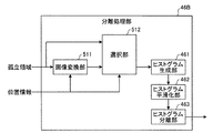
図26は、変形例2に係る分離処理部46Bの構成を模式的に示す図である。図26に示すように、分離処理部46Bは、画像変換部511、選択部512、ヒストグラム生成部461、ヒストグラム平滑化部462及びヒストグラム分離部463等の機能部を備える。なお、画像変換部511は、変形例1で説明した選択機能を備えてもよいし、備えなくてもよい。
FIG. 26 is a diagram schematically illustrating a configuration of a
ここで、選択部512には、孤立領域検出部45で検出された孤立領域と、画像変換部511で変換された孤立領域と、各孤立領域の位置情報とが入力される。選択部512は、各孤立領域の位置情報に基づき、入力された孤立領域の中からヒストグラム分離部463に出力する孤立領域を選択する。具体的に、選択部512は、変形が生じる領域の孤立領域については、画像変換部511で変換された孤立領域を選択し、変形が生じない領域の孤立領域については、孤立領域検出部45で検出された孤立領域を選択する。なお、選択の基準となる領域は、例えば、図21に示した領域G1、G2を用いてもよい。
Here, the
このように、本変形例の分離処理部46Bでは、遠方且つ画角端で検出された孤立領域であっても、孤立領域に含まれる画素群の形状を補正することができるため、変形例1と同様、孤立領域の分離を容易に行うことができる。
As described above, the
[変形例3]
上記変形例1、2では、画像変換部511で孤立領域に変換処理を施した後、この変化処理後の孤立領域に基づいてヒストグラムを生成する構成を説明した。変形例3では、画像変換部511を用いずに、ヒストグラムの生成を行う構成について説明する。以下、本変形例に係る分離処理部46Cの構成について説明する。分離処理部46Cは、上記実施形態の分離処理部46に対応するものである。なお、上記実施形態及び変形例と同様の構成については、同一の符号を付与し説明を省略する。
[Modification 3]
In the first and second modifications, the configuration has been described in which the
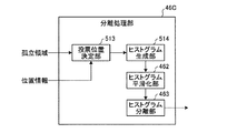
図27は、変形例3に係る分離処理部46Cの構成を模式的に示す図である。図27に示すように、分離処理部46Cは、投票位置決定部513、ヒストグラム生成部514、ヒストグラム平滑化部462及びヒストグラム分離部463等の機能部を備える。
FIG. 27 is a diagram schematically illustrating the configuration of a
投票位置決定部513には、孤立領域検出部45で検出された孤立領域と、各孤立領域の位置情報とが入力される。投票位置決定部513は、孤立領域の各々について、当該孤立領域のエリア内に存在する各画素(有効画素)の投票位置を決定する。ここで、投票位置は、その有効画素の視差頻度に係るヒストグラムのビンの位置、つまり第2Uマップの横座標の位置を指定するものである。なお、投票位置決定部513は、上記式(6)に基づき算出した画素位置xnewを、投票位置として決定するものとする。
The voting
また、投票位置決定部513は、孤立領域毎に、有効画素の視差頻度と当該有効画素の投票位置とを対応付け、ヒストグラム生成部514に出力する。
In addition, the voting
ヒストグラム生成部514は、投票位置決定部513から入力される有効画素の視差頻度と投票位置とに基づき、孤立領域毎にヒストグラムを生成する。ここで、ヒストグラム生成部514が生成するヒストグラムは、孤立領域に生じた変形の補正後の結果を反映したものとなる。そのため、ヒストグラム分離部463では、ヒストグラム生成部514が生成したヒストグラムから、孤立領域の分離を容易に行うことができる。
The
このように、本変形例の分離処理部46Cでは、遠方且つ画角端で検出された孤立領域であっても、補正後の結果を反映したヒストグラムを生成することができるため、上記変形例と同様、孤立領域の分離を容易に行うことができる。
As described above, since the
以上、本発明のいくつかの実施形態を説明したが、これらの実施形態は、例として提示したものであり、発明の範囲を限定することは意図していない。これら新規な実施形態は、その他の様々な形態で実施されることが可能であり、発明の要旨を逸脱しない範囲で、種々の省略、置き換え、変更を行うことができる。これら実施形態やその変形は、発明の範囲や要旨に含まれるとともに、特許請求の範囲に記載された発明とその均等の範囲に含まれる。 As mentioned above, although some embodiment of this invention was described, these embodiment is shown as an example and is not intending limiting the range of invention. These novel embodiments can be implemented in various other forms, and various omissions, replacements, and changes can be made without departing from the scope of the invention. These embodiments and modifications thereof are included in the scope and gist of the invention, and are included in the invention described in the claims and the equivalents thereof.
例えば、上記実施形態では、撮像部10としてステレオカメラを用いる形態を説明したが、これに限らないものとする。例えば、撮像部10として、被写体との距離(奥行き)を示す距離情報を画素毎に含む画像データ(距離画像)を取得可能な、単眼の距離画像カメラを用いる構成としてもよい。また、レーザ等の測距手段と、通常の単眼カメラとを組み合わせることで、距離画像を取得可能な構成としてもよい。これらの構成を採用した場合、被写体との距離は、視差値dの逆数に比例するため、距離画像に基づき、視差画像や第1Uマップ、第2Uマップ等を生成することができる。
For example, in the above-described embodiment, a configuration in which a stereo camera is used as the
また、上記実施形態では、視差頻度分布情報としてヒストグラムの画像を用いて説明したが、これは説明を容易にするために例として示したものである。画像解析部20で孤立領域の分離を行う際、ヒストグラム生成部461は、実際にヒストグラムを画像として生成する必要はない。例えば、ヒストグラム生成部461は、例えばヒストグラムを表す数値情報を、視差頻度分布情報として生成してもよい。
In the embodiment described above, the histogram image is used as the parallax frequency distribution information. However, this is shown as an example for ease of explanation. When the isolated region is separated by the
1 車両制御システム
10 撮像部
20 画像解析部
30 車両制御部
41 平行化画像生成部
42 視差画像生成部
43 第1Uマップ生成部
44 第2Uマップ生成部
45 孤立領域検出部
46、46A、46B、46C 分離処理部
47 対応領域検出部
48 オブジェクトタイプ分類部
49 3次元位置決定部
461 ヒストグラム生成部
462 ヒストグラム平滑化部
463 ヒストグラム分離部
511 画像変換部
512 選択部
513 投票位置決定部
514 ヒストグラム生成部
DESCRIPTION OF
Claims (10)
前記画像の一軸方向での画素位置と、当該画素位置での視差値と、当該視差値が出現する視差頻度とを対応付けた第1マップを生成する第1生成手段と、
前記第1マップでの画素位置の単位を、実距離の単位に変換した第2マップを生成する第2生成手段と、
前記第2マップにおいて、所定値以上の視差頻度を有する連結した画素群の領域を、物体が存在する孤立領域として検出する検出手段と、
前記孤立領域を構成する各画素の視差頻度に基づいて、前記孤立領域を分割する分割手段と、
を備える物体検出装置。 Image input means for inputting an image including parallax information or distance information for each pixel;
First generation means for generating a first map that associates a pixel position in the uniaxial direction of the image, a parallax value at the pixel position, and a parallax frequency at which the parallax value appears;
Second generation means for generating a second map obtained by converting a unit of a pixel position in the first map into a unit of an actual distance;
In the second map, detection means for detecting a region of connected pixel groups having a parallax frequency equal to or higher than a predetermined value as an isolated region where an object exists;
Dividing means for dividing the isolated region based on the parallax frequency of each pixel constituting the isolated region;
An object detection apparatus comprising:
前記分割手段は、前記視差頻度分布情報に基づいて、前記孤立領域を分割する請求項1に記載の物体検出装置。 Further comprising third generation means for generating disparity frequency distribution information for each pixel position based on the disparity frequency of each pixel constituting the isolated region;
The object detection apparatus according to claim 1, wherein the dividing unit divides the isolated region based on the parallax frequency distribution information.
前記分割手段は、前記平滑化手段で平滑化されたヒストグラムに基づき、前記孤立領域を分割する請求項3〜6の何れか一項に記載の物体検出装置。 Smoothing means for smoothing the histogram generated by the third generating means;
The object detection device according to claim 3, wherein the dividing unit divides the isolated region based on a histogram smoothed by the smoothing unit.
前記画像の一軸方向での画素位置と、当該画素位置での視差値と、当該視差値が出現する視差頻度とを対応付けた第1マップを生成し、
前記第1マップでの画素位置の単位を、実距離の単位に変換した第2マップを生成し、
前記第2マップにおいて、所定値以上の視差頻度を有する連結した画素群の領域を、物体が存在する孤立領域として検出し、
前記孤立領域を構成する各画素の視差頻度に基づいて、前記孤立領域を分割する、
ことを含む物体検出方法。 Input an image containing parallax information or distance information for each pixel,
Generating a first map in which a pixel position in the uniaxial direction of the image, a parallax value at the pixel position, and a parallax frequency at which the parallax value appears are associated with each other;
Generating a second map obtained by converting a unit of a pixel position in the first map into a unit of an actual distance;
In the second map, a region of connected pixel groups having a parallax frequency equal to or higher than a predetermined value is detected as an isolated region where an object exists,
Dividing the isolated region based on the parallax frequency of each pixel constituting the isolated region;
An object detection method.
画素毎に視差情報又は距離情報を含んだ画像を入力する画像入力手段と、
前記画像の一軸方向での画素位置と、当該画素位置での視差値と、当該視差値が出現する視差頻度とを対応付けた第1マップを生成する第1生成手段と、
前記第1マップでの画素位置の単位を、実距離の単位に変換した第2マップを生成する第2生成手段と、
前記第2マップにおいて、所定値以上の視差頻度を有する連結した画素群の領域を、物体が存在する孤立領域として検出する検出手段と、
前記孤立領域を構成する各画素の視差頻度に基づいて、前記孤立領域を分割する分割手段と、
して機能させるためのプログラム。 The computer of the object detection device
Image input means for inputting an image including parallax information or distance information for each pixel;
First generation means for generating a first map that associates a pixel position in the uniaxial direction of the image, a parallax value at the pixel position, and a parallax frequency at which the parallax value appears;
Second generation means for generating a second map obtained by converting a unit of a pixel position in the first map into a unit of an actual distance;
In the second map, detection means for detecting a region of connected pixel groups having a parallax frequency equal to or higher than a predetermined value as an isolated region where an object exists;
Dividing means for dividing the isolated region based on the parallax frequency of each pixel constituting the isolated region;
Program to make it function.
Priority Applications (2)
| Application Number | Priority Date | Filing Date | Title |
|---|---|---|---|
| JP2015135574A JP6592991B2 (en) | 2015-07-06 | 2015-07-06 | Object detection apparatus, object detection method, and program |
| EP16177194.4A EP3115966B1 (en) | 2015-07-06 | 2016-06-30 | Object detection device, object detection method, and computer program |
Applications Claiming Priority (1)
| Application Number | Priority Date | Filing Date | Title |
|---|---|---|---|
| JP2015135574A JP6592991B2 (en) | 2015-07-06 | 2015-07-06 | Object detection apparatus, object detection method, and program |
Publications (2)
| Publication Number | Publication Date |
|---|---|
| JP2017016584A true JP2017016584A (en) | 2017-01-19 |
| JP6592991B2 JP6592991B2 (en) | 2019-10-23 |
Family
ID=56683709
Family Applications (1)
| Application Number | Title | Priority Date | Filing Date |
|---|---|---|---|
| JP2015135574A Expired - Fee Related JP6592991B2 (en) | 2015-07-06 | 2015-07-06 | Object detection apparatus, object detection method, and program |
Country Status (2)
| Country | Link |
|---|---|
| EP (1) | EP3115966B1 (en) |
| JP (1) | JP6592991B2 (en) |
Cited By (6)
| Publication number | Priority date | Publication date | Assignee | Title |
|---|---|---|---|---|
| JP2020160914A (en) * | 2019-03-27 | 2020-10-01 | 株式会社豊田自動織機 | Object detection device |
| JP2021022322A (en) * | 2019-07-30 | 2021-02-18 | 株式会社リコー | Image processing device, object recognition device, apparatus control system, image processing method, and program |
| KR20210081527A (en) * | 2019-12-24 | 2021-07-02 | 동의대학교 산학협력단 | Apparatus and method for improving the performance of stereo-based ROI detection algorithm |
| JP7138265B1 (en) * | 2021-06-17 | 2022-09-15 | ヌヴォトンテクノロジージャパン株式会社 | OBJECT DETECTION DEVICE, OBJECT DETECTION METHOD AND PROGRAM |
| WO2022264894A1 (en) * | 2021-06-17 | 2022-12-22 | ヌヴォトンテクノロジージャパン株式会社 | Object detecting device, object detecting method, and program |
| WO2024042607A1 (en) * | 2022-08-23 | 2024-02-29 | 日立Astemo株式会社 | External world recognition device and external world recognition method |
Families Citing this family (1)
| Publication number | Priority date | Publication date | Assignee | Title |
|---|---|---|---|---|
| JP2019160248A (en) * | 2018-03-16 | 2019-09-19 | 株式会社リコー | Information processing device, system, mobile body, information processing method and program |
Citations (2)
| Publication number | Priority date | Publication date | Assignee | Title |
|---|---|---|---|---|
| JP2015011619A (en) * | 2013-07-01 | 2015-01-19 | 株式会社リコー | Information detection device, mobile equipment control system, mobile body and program for information detection |
| JP2015207281A (en) * | 2014-04-10 | 2015-11-19 | 株式会社リコー | Solid detector, solid detection method, solid detection program, and mobile body equipment control system |
Family Cites Families (1)
| Publication number | Priority date | Publication date | Assignee | Title |
|---|---|---|---|---|
| JP6013884B2 (en) | 2012-11-08 | 2016-10-25 | 日立オートモティブシステムズ株式会社 | Object detection apparatus and object detection method |
-
2015
- 2015-07-06 JP JP2015135574A patent/JP6592991B2/en not_active Expired - Fee Related
-
2016
- 2016-06-30 EP EP16177194.4A patent/EP3115966B1/en active Active
Patent Citations (2)
| Publication number | Priority date | Publication date | Assignee | Title |
|---|---|---|---|---|
| JP2015011619A (en) * | 2013-07-01 | 2015-01-19 | 株式会社リコー | Information detection device, mobile equipment control system, mobile body and program for information detection |
| JP2015207281A (en) * | 2014-04-10 | 2015-11-19 | 株式会社リコー | Solid detector, solid detection method, solid detection program, and mobile body equipment control system |
Non-Patent Citations (2)
| Title |
|---|
| "STEREO VISION BASED VEHICLE DETECTION", [ONLINE], JPN7019001767, 2010, ISSN: 0004100909 * |
| TARAK GANDHI ET AL.: "Vehicle Surround Capture: Survey of Techniques and a Novel Omni-Video-Based Approach for Dynamic Pan", [ONLINE], JPN6019020400, 2006, ISSN: 0004100908 * |
Cited By (8)
| Publication number | Priority date | Publication date | Assignee | Title |
|---|---|---|---|---|
| JP2020160914A (en) * | 2019-03-27 | 2020-10-01 | 株式会社豊田自動織機 | Object detection device |
| JP2021022322A (en) * | 2019-07-30 | 2021-02-18 | 株式会社リコー | Image processing device, object recognition device, apparatus control system, image processing method, and program |
| JP7306139B2 (en) | 2019-07-30 | 2023-07-11 | 株式会社リコー | Image processing device, object recognition device, device control system, image processing method and program |
| KR20210081527A (en) * | 2019-12-24 | 2021-07-02 | 동의대학교 산학협력단 | Apparatus and method for improving the performance of stereo-based ROI detection algorithm |
| KR102430120B1 (en) | 2019-12-24 | 2022-08-05 | 동의대학교 산학협력단 | Apparatus and method for improving the performance of stereo-based ROI detection algorithm |
| JP7138265B1 (en) * | 2021-06-17 | 2022-09-15 | ヌヴォトンテクノロジージャパン株式会社 | OBJECT DETECTION DEVICE, OBJECT DETECTION METHOD AND PROGRAM |
| WO2022264894A1 (en) * | 2021-06-17 | 2022-12-22 | ヌヴォトンテクノロジージャパン株式会社 | Object detecting device, object detecting method, and program |
| WO2024042607A1 (en) * | 2022-08-23 | 2024-02-29 | 日立Astemo株式会社 | External world recognition device and external world recognition method |
Also Published As
| Publication number | Publication date |
|---|---|
| JP6592991B2 (en) | 2019-10-23 |
| EP3115966A1 (en) | 2017-01-11 |
| EP3115966B1 (en) | 2020-03-04 |
Similar Documents
| Publication | Publication Date | Title |
|---|---|---|
| JP6592991B2 (en) | Object detection apparatus, object detection method, and program | |
| US10580155B2 (en) | Image processing apparatus, imaging device, device control system, frequency distribution image generation method, and recording medium | |
| JP6013884B2 (en) | Object detection apparatus and object detection method | |
| JP6274557B2 (en) | Moving surface information detection apparatus, moving body device control system using the same, and moving surface information detection program | |
| CN110023951B (en) | Information processing apparatus, image forming apparatus, device control system, information processing method, and computer-readable recording medium | |
| JP7206583B2 (en) | Information processing device, imaging device, device control system, moving object, information processing method and program | |
| US11691585B2 (en) | Image processing apparatus, imaging device, moving body device control system, image processing method, and program product | |
| WO2017138245A1 (en) | Image processing device, object recognition device, device control system, and image processing method and program | |
| JP6743882B2 (en) | Image processing device, device control system, imaging device, image processing method, and program | |
| WO2014002692A1 (en) | Stereo camera | |
| JP6816401B2 (en) | Image processing device, imaging device, mobile device control system, image processing method, and program | |
| WO2017094300A1 (en) | Image processing device, object recognition device, device conrol system, image processing method, and program | |
| JPH11351862A (en) | Foregoing vehicle detecting method and equipment | |
| JP6753134B2 (en) | Image processing device, imaging device, mobile device control system, image processing method, and image processing program | |
| JP5073700B2 (en) | Object detection device | |
| JP2012252501A (en) | Traveling path recognition device and traveling path recognition program | |
| JP2023184572A (en) | Electronic apparatus, movable body, imaging apparatus, and control method for electronic apparatus, program, and storage medium | |
| JP2017211791A (en) | Image processing device, imaging device, mobile body equipment control system, image processing method, and program | |
| JP2017207881A (en) | Image processing apparatus, imaging apparatus, moving body device control system, image processing method, and program | |
| WO2018097269A1 (en) | Information processing device, imaging device, equipment control system, mobile object, information processing method, and computer-readable recording medium | |
| JP2018092608A (en) | Information processing device, imaging device, apparatus control system, movable body, information processing method, and program | |
| JP7087499B2 (en) | Image processing equipment, object recognition equipment, equipment control systems, moving objects, image processing methods and programs | |
| JP2019160251A (en) | Image processing device, object recognition device, instrument control system, moving body, image processing method and program | |
| JP2018088237A (en) | Information processing device, imaging device, apparatus control system, movable body, information processing method, and information processing program | |
| JP6334773B2 (en) | Stereo camera |
Legal Events
| Date | Code | Title | Description |
|---|---|---|---|
| A621 | Written request for application examination |
Free format text: JAPANESE INTERMEDIATE CODE: A621 Effective date: 20180622 |
|
| A977 | Report on retrieval |
Free format text: JAPANESE INTERMEDIATE CODE: A971007 Effective date: 20190523 |
|
| A131 | Notification of reasons for refusal |
Free format text: JAPANESE INTERMEDIATE CODE: A131 Effective date: 20190604 |
|
| A521 | Request for written amendment filed |
Free format text: JAPANESE INTERMEDIATE CODE: A523 Effective date: 20190805 |
|
| TRDD | Decision of grant or rejection written | ||
| A01 | Written decision to grant a patent or to grant a registration (utility model) |
Free format text: JAPANESE INTERMEDIATE CODE: A01 Effective date: 20190827 |
|
| A61 | First payment of annual fees (during grant procedure) |
Free format text: JAPANESE INTERMEDIATE CODE: A61 Effective date: 20190909 |
|
| R151 | Written notification of patent or utility model registration |
Ref document number: 6592991 Country of ref document: JP Free format text: JAPANESE INTERMEDIATE CODE: R151 |
|
| LAPS | Cancellation because of no payment of annual fees |