JP2017015609A - Flow rate measuring device and liquid processing system - Google Patents
Flow rate measuring device and liquid processing system Download PDFInfo
- Publication number
- JP2017015609A JP2017015609A JP2015133959A JP2015133959A JP2017015609A JP 2017015609 A JP2017015609 A JP 2017015609A JP 2015133959 A JP2015133959 A JP 2015133959A JP 2015133959 A JP2015133959 A JP 2015133959A JP 2017015609 A JP2017015609 A JP 2017015609A
- Authority
- JP
- Japan
- Prior art keywords
- flow rate
- liquid
- flow path
- flow
- rate measuring
- Prior art date
- Legal status (The legal status is an assumption and is not a legal conclusion. Google has not performed a legal analysis and makes no representation as to the accuracy of the status listed.)
- Pending
Links
Images


Landscapes
- Measuring Volume Flow (AREA)
- Examining Or Testing Airtightness (AREA)
Abstract
Description
本発明は、液漏れ検知を行える流量計測装置及び流体処理システムに関する。 The present invention relates to a flow rate measuring device and a fluid processing system capable of detecting liquid leakage.
従来から、流量計測装置は、例えば、半導体製造装置を始め流体を使用する各種の装置に装着されている。近年の装置の高度化に伴い、一つの装置に使用される流量計測装置も多機能化が進んでいる。例えば、流体の流量だけでなく、温度を計測する機能も備えた複合型の計測器が提案されている(特許文献1参照)。この様な多機能化は、装置の小型化やコストダウンに貢献すると共に、装置内の配線作業を減らし装置の製造をしやすくすることにも役立っている。 2. Description of the Related Art Conventionally, flow rate measuring devices are mounted on various devices that use fluids, for example, semiconductor manufacturing devices. Along with the advancement of devices in recent years, the flow rate measuring device used in one device is also becoming more multifunctional. For example, a composite measuring instrument having a function of measuring not only the flow rate of fluid but also temperature has been proposed (see Patent Document 1). Such multi-functionality contributes to downsizing and cost reduction of the apparatus, and also helps to reduce the wiring work in the apparatus and facilitate the manufacture of the apparatus.
本発明は、液漏れ検知機能を有する流量計測装置及び液体処理システムを提供する。 The present invention provides a flow rate measuring device and a liquid processing system having a liquid leakage detection function.
本発明の流量計測装置は、液体が流れる流路を形成する流路形成部材と、前記流路形成部材に設けられ前記流路内を流れる液体の流量を計測する流量計測手段と、前記流量計測手段よりも下流側に配置され前記流路を開閉する開閉手段と、前記流路が閉状態のときの前記流量計測手段の検知結果に基づいて、前記流路のうち前記流量計測手段による流量計測位置と前記開閉手段による流路開閉位置との間の判定区間における液漏れを判定する液漏れ判定手段と、を備えたことを特徴とする。
かかる本発明の態様によれば、流路を閉じた後の流量検知結果に基づいて、液漏れ検知を行うことができる。
The flow rate measuring device of the present invention includes a flow channel forming member that forms a flow channel through which a liquid flows, a flow rate measuring unit that is provided in the flow channel forming member and that measures a flow rate of the liquid that flows through the flow channel, and the flow rate measuring device. On the basis of the detection result of the flow rate measuring means when the flow path is closed, the flow rate measurement by the flow rate measuring means among the flow paths is arranged downstream of the means and opens and closes the flow path A liquid leakage determination means for determining liquid leakage in a determination section between the position and the flow path opening / closing position by the opening / closing means.
According to this aspect of the present invention, it is possible to detect liquid leakage based on the flow rate detection result after closing the flow path.
また、上記本発明では、前記判定区間には、流路内の液体に対して、或は流路内の液体を用いて所定の処理を行う処理装置が設けられたことを特徴としてもよい。
かかる本発明の態様によれば、処理装置に供給する液量を管理できる。
In the present invention, the determination section may be provided with a processing device that performs a predetermined process on the liquid in the flow path or using the liquid in the flow path.
According to this aspect of the present invention, the amount of liquid supplied to the processing apparatus can be managed.
また、上記本発明では、更に、前記液漏れ判定手段の検知結果に基づいて、前記判定区間で液漏れが発生したことを外部に報知する報知手段を備えたことを特徴としてもよい。
かかる本発明の態様によれば、液漏れ発生の事象を関係者に直ぐに知らせることができる。
Further, the present invention may further comprise notifying means for notifying the outside that a liquid leak has occurred in the determination section based on a detection result of the liquid leak determining means.
According to this aspect of the present invention, it is possible to immediately notify the person concerned of the occurrence of liquid leakage.
また、上記本発明では、前記液漏れ判定手段は、前記流量計測手段が検知する流量の積算値が所定の閾値以上になった場合において、前記判定区間で液漏れが発生したことを検知することを特徴としてもよい。
かかる本発明の態様によれば、例えば、所定の閾値を設定することにより、液漏れ判定をその程度やレベル分けによって実施できる。
Moreover, in the said invention, the said liquid leak determination means detects that the liquid leak generate | occur | produced in the said determination area, when the integrated value of the flow volume which the said flow measurement means detects becomes more than a predetermined threshold value. May be a feature.
According to this aspect of the present invention, for example, by setting a predetermined threshold value, the liquid leakage determination can be performed according to the degree or level.
なお、本発明は、上述した流量計測装置を所定の配管経路に設置した流体処理システムについても広く適用できる。
かかる本発明によれば、流体処理を行う過程において、液漏れ判定しながら流量計測が行えるため、流体処理の管理負荷を低減できる。
The present invention can be widely applied to a fluid processing system in which the above-described flow rate measuring device is installed in a predetermined piping path.
According to the present invention, in the process of performing the fluid treatment, the flow rate can be measured while determining the liquid leakage, so that the management load of the fluid treatment can be reduced.
本発明によれば、液漏れ検知機能を有する流量計測装置及び液体処理システムを実現できる。 ADVANTAGE OF THE INVENTION According to this invention, the flow measuring device and liquid processing system which have a liquid leak detection function are realizable.
以下、図面を参照して、本発明を実施の形態に基づいて詳細に説明する。
図1には本発明の一実施形態に係る流量計測装置及び流体処理システムの概略構成図を示すと共に、図1の流量計測装置の要部として、図2には開閉バルブの概略構成図を示し、図3には流量検知構造流路の概略構成図を示す。
DESCRIPTION OF EMBODIMENTS Hereinafter, the present invention will be described in detail based on embodiments with reference to the drawings.
1 shows a schematic configuration diagram of a flow rate measuring device and a fluid processing system according to an embodiment of the present invention, and FIG. 2 shows a schematic configuration diagram of an on-off valve as a main part of the flow rate measuring device of FIG. FIG. 3 shows a schematic configuration diagram of the flow rate detection structure flow path.
図示するように、本実施形態の流体処理システム100は、流体が流れる流路1を形成する一対の流路形成部材10と、これら流路形成部材10の間に連結された液体処理装置20と、この流体処理装置20の前後で流量計測する流量計測装置30とを備える。
As shown in the figure, a
ここで、液体処理装置20は、例えば、本実施形態では、液体を加熱する装置であるが、他の処理を行う装置でもよい。なお、このような液体処理装置20は、流路形成部材10に設けなくてもよく、その場合は、流路監視システムとなる。
Here, for example, in the present embodiment, the
また、流路形成部材10は、例えば、円筒状の配管(パイプ)から構成され、液体処理装置20の上流側にてフランジを有する接続部材11により連結されて液体処理装置20内に液体を供給する第1配管10aと、液体処理装置20の下流側にて処理後の液体を下流側に流すためにフランジ11を有する接続部材11によって連結され液体処理装置20から排出される液体を受ける第2配管10bと、を有する。
Further, the flow path forming member 10 is constituted by, for example, a cylindrical pipe (pipe), and is connected by a
さらに、流量計測装置30は、例えば、本実施形態では、液体処理装置20の上流側において流路1内を流れる液体の流量を計測するために設けられた流量検知構造部310と、液体処理装置20の下流側において流路を開閉する流路開閉部となる開閉バルブ320と、流量検知構造部310の信号310a及び開閉バルブ320からの信号320aを受けて流量計測と液漏れ判断を行う流量計測装置本体330とを有する。
Furthermore, in the present embodiment, the flow
ここで、流量検知構造部310は、図1及び図3に示すように、第1配管10aに接続される筒状の連結配管311と、この連結配管311内の流路1において流体の流れを受けて回転する磁石312a付のスクリュー312と、このスクリュー312を回転可能に保持する軸受部313と、連結配管311の側面に設けられ流路形成部材10の外側からスクリュー312の回転に伴う磁界変化を検出する磁気センサ314とを有する。磁気センサ314は、スクリュー312の回転に伴って発生する磁気変化を検出しその磁気変化の検出結果から流量を算出することが出来る。このため、310は流量の計測センサとして機能する。
Here, as shown in FIG. 1 and FIG. 3, the flow rate
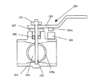
一方、開閉バルブ320は、第2配管10bに接続される筒状の連結配管321と、この連結配管10b内の流路で回動する円板状のディスク部材322と、ディスク部材322を回転可能に保持する軸部323と、ディスク部材322を回動させる手動レバー324とを有し、連結配管321の外側に配置された手動レバー324によって流路1内のディスク部材322を回転させ、連結配管321の外側から流路1を開閉する構造を有する。
On the other hand, the opening /
なお、手動レバー324は、ナット325によって軸部323に固定され、手動レバー324と連結配管321との係合部は、液漏れを防ぐためにシール部材326を介して回動自在に設けられ、その部分を更に封止部材327で塞いでいる。
The
例えば、本実施形態では、手動レバー324の向きを流路1内の液流れ方向に対して略平行に向けるとディスク部材322が流路1を開き、流路1内の液流れが開放される。一方、手動レバー324を流路1の液流れ方向と略直交する方向にすると、ディスク部材322が回転して流路1の液流れが遮断される。このディスク部材322の外周にはシール部材322aが固定されており、ディスク部材322と連結配管321との間を封止する。なお、本実施形態では、手動作業で流路1を開閉するようにしたが、例えば、自動でディスク部材322を回動させて流路1の開閉を行うようにしてもよい。
For example, in this embodiment, when the direction of the
ここで、このような開閉バルブ320には、手動レバー324の下端面に磁石324aが固定され、その磁石324aに対向する連結配管321の上端面には磁気センサ328が配置される。すなわち、手動レバー324を回動させて磁石324aと磁気センサ328とが対向する位置(すなわち、流路1の全開位置)を検知できるようになっている。つまり、この磁気センサ328は、開閉バルブ320の開閉検知の手段となり、開閉バルブ320が閉状態である旨の信号320aを流量計測装置本体330に通知する。
Here, in such an open /
そして、本実施形態の流体処理システム100では、開閉バルブ320が開状態となり、流体が流路1内を流れると磁石312aと共にスクリュー312が回転し、磁気センサ314によってスクリュー312の回転数情報(信号)を流量計測装置本体330に送信する。
In the
これにより、流量計測装置本体330では、開閉バルブ320から磁気センサ314の信号を受けて、開閉バルブ320(ディスク322)が開状態から閉状態になったと判断すると、その閉状態において、流量検知構造部310の磁気センサ314から受信した信号310aの処理によって液漏れを検知し、警報信号330aを所定の宛先に出力する。
As a result, in the flow rate measuring device
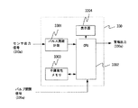
ここで、図5には、本実施形態の流量計測装置における液漏れ検知を行う流量計測装置本体の機能ブロック図を示す。図5に示すように、流量計測装置本体330は、磁気センサ314からセンサ出力信号310aがパルス周期計測手段3301に入力されると、パルス周期計測手段3301が流路1内に流れている液体の流量を計測する。例えば、液漏れが生じていない場合には、CPU3302は表示器3304を通じて流量値を表示する。本実施形態では表示器3304を設けて表示するようにしたが、流量値を所定の宛先に通知するような仕組みとしてもよい。
Here, FIG. 5 shows a functional block diagram of the main body of the flow rate measuring device that performs liquid leak detection in the flow rate measuring device of the present embodiment. As shown in FIG. 5, when the
ここで、液漏れが生じているか否かは、CPU3302が判断する。例えば、磁気センサ328から開閉バルブ320が閉状態であることを示すセンサ出力信号(閉信号)320aがCPU3302に入力後、パルス周期計測手段3301が計測する流量が所定の期間内で閾値を超えていると判断した場合、液漏れが発生していると判断する。
Here, the
すなわち、CPU3302は、磁気センサ328からのセンサ出力信号(閉信号)320aを受信するまで液漏れ判定せずに流量値を表示器3304に表示し、センサ出力信号(閉信号)320aを受信すると液漏れ検知を開始する。そして、液漏れ検知の結果、流量が閾値を超えると、異常信号330aの出力を行う。このとき、表示器3304には、液漏れ検知開始後の流量を表示するようにしてもよいし、異常判断した後は、異常であることを表示するようにしてもよい。このように、CPU3302は、液漏れを判断し、閾値を超えると警報信号330aを出力することから、液漏れ検知手段だけでなく警報を行う報知手段としての役割も有する。
That is, the
なお、液漏れ検知の閾値は、後述するが、ユーザによる設定値としてもよいし、1つの閾値でもよいし、複数の異なる閾値を設定し、その閾値毎に異なる警報信号330aを出力してもよい。また、液漏れ検知の閾値は、図5に示す不揮発性メモリ3303に予め記憶されており、CPU3302は、センサ出力信号(閉信号)320aを受信したら不揮発性メモリ3303から閾値(センサ出力信号320aを受信する前にユーザにより更新されていれば最新の閾値)を読出し、液漏れ検知を行う。
As will be described later, the liquid leakage detection threshold value may be set by the user, may be a single threshold value, or may be set to a plurality of different threshold values, and a
以上説明したように、流量計測装置本体330の制御部3302が、流量検知構造部310と開閉バルブ320との間の区間(判定区間)における液漏れ検知手段としての機能を果たす。つまり、本実施形態の流量計測装置本体330では、開閉バルブ320の状態にかかわらず流量計測を行うが、開閉バルブ320が閉状態のときは液漏れ検知を併せて行い、液漏れの場合は警報を発する。なお、上記警報の形式は、例えば、電気信号、音、光、機械的振動、あるいはこれらの組み合わせが可能である。
As described above, the
ここで、図4及び図5を参照し、液漏れ検知における判断ステップの一実施例について具体的に説明する。
まず、ステップS401において、ユーザによって初期設定がなされると、その初期設定は不揮発性メモリ3303に記憶される。ユーザによる初期設定がなされなかった場合は、不揮発性メモリ3303に記憶されていた設定情報に従って装置の設定が行われる。次に、ステップS402において、流量計測が行われる。そして、ステップS402で開始された流量計測中において、開閉バルブ320が閉じているか否かを確認する(ステップS403)。具体的には、開閉バルブ320に付随する磁気センサ328から開閉バルブ320が閉状態であることを示すセンサ出力信号(閉信号)320aがCPU3302に入力されたか否かを確認する。ステップS403においてNOの場合(開閉バルブ320が開状態の場合)には、計測した流量を表示器3304に表示し、再びステップS402に戻る。一方、ステップS403においてYESの場合(開閉バルブ320が閉状態の場合)には、計測した流量が閾値を超えているかを判定する(ステップS405)。ステップS405において計測した流量が閾値を超えていない場合(NOの場合)には、その流量を表示器3304に表示し、再びステップS402の流量計測に戻る。これに対し、ステップS405において計測した流量が閾値を超えたと判定した場合(YESの場合)には、予め設定された方法で警報出力を実施する(ステップS406)。これにより、液漏れを早期に確認することが可能となる。液漏れしたと判断するための閾値は、ステップS401にてユーザが予め設定した値を使うが、その場合、閾値を複数設けて、液漏れの程度を複数のランクに分けて検知できるようにしてもよい。
Here, with reference to FIG.4 and FIG.5, one Example of the determination step in a liquid leak detection is described concretely.
First, in
なお、ステップS406においては、流路に設置した開閉バルブが閉まっている状態で、開閉バルブ302よりも上流側に設置された磁気センサ(あるいは、スクリュー回転により流量を直接検知する流量センサでも可)314が発する信号が一定以上の流量を示したときに、磁気センサ314よりも下流側で装置の故障が発生し、流体が漏洩していると判断し、警報信号330aとして、どこの区間でどの程度液漏れが発生しているかの情報を含めて警報を発するようにしてもよい。これにより、液漏れが発生した流路区間の上流側で、液漏れがない別の流路区間に切り替えたり、あるいは現場に急行して液漏れ区間を重点的に確認したりして、早期の対応を実施できる。
In step S406, a magnetic sensor installed upstream of the open / close valve 302 with the open / close valve installed in the flow path closed (or a flow sensor that directly detects the flow rate by screw rotation may be used). When the signal generated by 314 indicates a flow rate above a certain level, it is determined that a device failure has occurred on the downstream side of the
また、本発明では、流路に設置した開閉バルブが閉まっている状態で、バルブよりも上流側に設置された磁気センサが発する信号を使って計算した流体の積算流量(累積流量値)が所定の値以上になったら、流量センサよりも下流側で装置の故障が発生して、流体が漏洩していると判断し警報を発するようにしてもよい。例えば、流量計測装置本体は、ディスク部材が流路を閉じている状態で、信号が検知した流体の流量が、予め設定した閾値よりも大きい場合、流路から流体が漏洩していると判断し、外部に対し警報信号を発する。 In the present invention, the integrated flow rate (cumulative flow rate value) calculated using a signal generated by a magnetic sensor installed upstream of the valve in a state where the open / close valve installed in the flow path is closed is predetermined. If the value is equal to or greater than the value, it may be determined that a failure of the apparatus has occurred on the downstream side of the flow sensor and the fluid is leaking, and an alarm is issued. For example, if the flow rate of the fluid detected by the signal is greater than a preset threshold value with the disk member closing the flow path, the flow rate measuring device body determines that the fluid is leaking from the flow path. An alarm signal is issued to the outside.
以上説明したように、本実施形態の流体処理システムによれば、流量計測を行いつつ簡単な構成で液漏れ検知ができ、異常がある場合には直ぐに外部(例えば、管理者等)に通知できるため、その後の対応を直ぐに行うことができる。また、流量検知と開閉バルブの開閉検知とを組み合わせて液漏れ検知するので、大掛かりな構成が不要になり、流量計測と共に低コストで液漏れ検知を実現できる。 As described above, according to the fluid treatment system of the present embodiment, liquid leakage can be detected with a simple configuration while performing flow rate measurement, and if there is an abnormality, it can be immediately notified to the outside (for example, an administrator). Therefore, the subsequent response can be performed immediately. Further, since the liquid leak detection is performed by combining the flow rate detection and the open / close detection of the on-off valve, a large-scale configuration is not required, and the liquid leak detection can be realized at a low cost together with the flow rate measurement.
<他の実施形態>
以上、本発明を一実施形態に基づいて説明したが、本発明は上述した一実施形態に限定されるものではない。
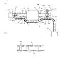
例えば、上述した一実施形態では、流路内の液流れの情報に基づいて漏洩検知するようにしたが、本発明は勿論これに限定されず、例えば、図6(a)及び図6(b)に示すように、流路から漏れた液体を検知する液漏れ検知装置40を組み合わせてもよい。例えば、図6(a)及び図6(b)に示すように、流路の配管に沿わせて2つの検知用導体41,42を敷設した構造を適用してもよい。
<Other embodiments>
As mentioned above, although this invention was demonstrated based on one Embodiment, this invention is not limited to one Embodiment mentioned above.
For example, in the above-described embodiment, leakage detection is performed based on the information on the liquid flow in the flow path. However, the present invention is not limited to this, and for example, FIG. 6 (a) and FIG. ), A liquid
この構成では、流体の漏出が例えば配管の接続部分において発生すると、漏洩した流体が連結部材43で連結された流体漏洩の検知用導体41,42の間の電気抵抗を低下させる。この電気抵抗の変化を、検知装置40で検出することにより、流路からの流体の漏洩を検出することができる。このような構造では、検知電極の腐食を防ぐ為に耐蝕性を持った素材の電極を使用できる。流量を使った液体の漏出を検知する仕組みと、実際に漏洩したことを検知する構造とを組み合わせて、より正確な漏洩検知を実現できる。
In this configuration, when fluid leakage occurs, for example, at a connection portion of the pipe, the leaked fluid reduces the electrical resistance between the fluid
なお、本発明による流量計測装置で漏洩検知を行うにあたって流路内で液体処理を伴う場合には、流体の流れの上流側に流量センサを配置し、流れの下流側にバルブを配置する必要がある。これを逆にすると、上流側で流路を閉じても内部に流体が残っており、流路内の流体が処理装置によって移動すると流量が変化してしまう可能性があり、望ましくない。 In addition, when liquid processing is involved in the flow path when performing leakage detection with the flow measurement device according to the present invention, it is necessary to arrange a flow sensor upstream of the fluid flow and a valve downstream of the flow. is there. Conversely, if the flow path is closed on the upstream side, the fluid remains inside, and the flow rate may change when the fluid in the flow path is moved by the processing apparatus, which is not desirable.
10 流路形成部材
20 液体処理装置
30 流量計測装置
100 液体処理システム
310 流量検知構造
320 開閉バルブ
DESCRIPTION OF SYMBOLS 10 Flow
Claims (5)
前記流路形成部材に接続され前記流路内を流れる液体の流量を計測する流量計測手段と、
前記流量計測手段よりも下流側に配置され前記流路を開閉する開閉手段と、
前記流路が閉状態のときの前記流量計測手段の検知結果に基づいて、前記流路のうち前記流量計測手段による流量計測位置と前記開閉手段による流路開閉位置との間の判定区間における液漏れを判定する液漏れ判定手段とを備えたことを特徴とする流量計測装置。 A flow path forming member that forms a flow path through which the liquid flows;
A flow rate measuring means connected to the flow path forming member for measuring the flow rate of the liquid flowing in the flow path;
Opening / closing means arranged on the downstream side of the flow rate measuring means for opening and closing the flow path,
Based on the detection result of the flow rate measurement means when the flow path is closed, the liquid in the determination section between the flow rate measurement position by the flow rate measurement means and the flow path opening / closing position by the opening / closing means in the flow path A flow rate measuring device comprising: a liquid leakage determining means for determining leakage.
Priority Applications (1)
| Application Number | Priority Date | Filing Date | Title |
|---|---|---|---|
| JP2015133959A JP2017015609A (en) | 2015-07-02 | 2015-07-02 | Flow rate measuring device and liquid processing system |
Applications Claiming Priority (1)
| Application Number | Priority Date | Filing Date | Title |
|---|---|---|---|
| JP2015133959A JP2017015609A (en) | 2015-07-02 | 2015-07-02 | Flow rate measuring device and liquid processing system |
Publications (1)
| Publication Number | Publication Date |
|---|---|
| JP2017015609A true JP2017015609A (en) | 2017-01-19 |
Family
ID=57827873
Family Applications (1)
| Application Number | Title | Priority Date | Filing Date |
|---|---|---|---|
| JP2015133959A Pending JP2017015609A (en) | 2015-07-02 | 2015-07-02 | Flow rate measuring device and liquid processing system |
Country Status (1)
| Country | Link |
|---|---|
| JP (1) | JP2017015609A (en) |
Cited By (1)
| Publication number | Priority date | Publication date | Assignee | Title |
|---|---|---|---|---|
| WO2022230530A1 (en) * | 2021-04-26 | 2022-11-03 | ナブテスコ株式会社 | Diagnosis system |
-
2015
- 2015-07-02 JP JP2015133959A patent/JP2017015609A/en active Pending
Cited By (1)
| Publication number | Priority date | Publication date | Assignee | Title |
|---|---|---|---|---|
| WO2022230530A1 (en) * | 2021-04-26 | 2022-11-03 | ナブテスコ株式会社 | Diagnosis system |
Similar Documents
| Publication | Publication Date | Title |
|---|---|---|
| JP7149458B2 (en) | gas meter | |
| JP2017015609A (en) | Flow rate measuring device and liquid processing system | |
| JP5140464B2 (en) | Ultrasonic gas meter | |
| JP2004219259A (en) | Gas meter | |
| JP2008267995A (en) | Flow presence determining method in gas meter | |
| JP2021047095A (en) | Failure diagnostic device and method | |
| JP2012127661A (en) | Method and device for detecting small gas leakage | |
| JPH10281914A (en) | Method for detecting leakage of cooling water | |
| JP2000074717A (en) | Device and method for monitoring abnormality in pressure and gas meter | |
| JP5914093B2 (en) | Gas shut-off device | |
| JPH10103547A (en) | Gas-blast circuit breaking device | |
| JP2010032535A (en) | Restoration security verification method and electronic gas meter | |
| JP2009097948A (en) | Gas meter | |
| JP3445677B2 (en) | Pipe capacity estimation device for gas meter | |
| JP4949922B2 (en) | Gas meter | |
| JP5154282B2 (en) | Flowmeter | |
| JP4486150B2 (en) | Gas shut-off device | |
| JP2007113632A (en) | Gas shut-off device | |
| JP7034854B2 (en) | Abnormality determination device and method | |
| JPH11132819A (en) | Gas meter | |
| JP2006017508A (en) | Gas meter | |
| JP2010169461A (en) | System for detecting gas leak | |
| JP2004333411A (en) | Water leak detection device and method of water supply system | |
| JP2005331373A (en) | Gas meter | |
| JP2009168739A (en) | Gas meter with self-diagnostic function |