JP2017013830A - Hinge cap - Google Patents
Hinge cap Download PDFInfo
- Publication number
- JP2017013830A JP2017013830A JP2015131482A JP2015131482A JP2017013830A JP 2017013830 A JP2017013830 A JP 2017013830A JP 2015131482 A JP2015131482 A JP 2015131482A JP 2015131482 A JP2015131482 A JP 2015131482A JP 2017013830 A JP2017013830 A JP 2017013830A
- Authority
- JP
- Japan
- Prior art keywords
- wall
- container
- plug
- cap
- hinge
- Prior art date
- Legal status (The legal status is an assumption and is not a legal conclusion. Google has not performed a legal analysis and makes no representation as to the accuracy of the status listed.)
- Granted
Links
Images


Abstract
Description
本発明は、容器の口部に装着されるヒンジキャップに関し、より詳しくは、注出筒を密封するために、上蓋と別体の栓体を備えるヒンジキャップに関するものである。 The present invention relates to a hinge cap that is attached to the mouth of a container, and more particularly to a hinge cap that includes a stopper that is separate from an upper lid in order to seal a dispensing cylinder.
従来、容器の口部には、内容物を注出するための注出筒を有するキャップが装着されている。この種のキャップとしては、容器の口部に装着し、注出筒を備えるキャップ本体と、注出筒を密封するインナーリングを備える上蓋とからなるヒンジキャップが知られている。
この種のヒンジキャップは、キャップ本体の上壁上面に注出筒を立設し、注出筒の内側にプルリングと除去部が設けられ、最初に内容物を注出する際に、プルリングを引っ張り上げて、除去部を取り除いて使用する必要がある。
しかしながら、力の弱い子供や女性および高齢の需要者からは、プルリングで除去部を取り除く抜栓作業を必要としないヒンジキャップが求められている。
このような抜栓作業を必要としないヒンジキャップとしては、インナーリングを有する内蓋を設けたヒンジキャップが知られている(例えば、特許文献1参照)。
Conventionally, a cap having a dispensing cylinder for dispensing contents is attached to the mouth of a container. As this type of cap, there is known a hinge cap that includes a cap body that is attached to the mouth of a container and includes a pour tube, and an upper lid that includes an inner ring that seals the pour tube.
This type of hinge cap has a pour tube standing upright on the upper surface of the upper wall of the cap body, and a pull ring and removal section are provided inside the pour tube, and the pull ring is pulled when the contents are first poured out. It is necessary to lift and remove the removal part.
However, a hinge cap that does not require an unplugging operation to remove the removal portion with a pull ring is demanded by weak children, women, and elderly consumers.
As a hinge cap that does not require such plugging work, a hinge cap provided with an inner lid having an inner ring is known (see, for example, Patent Document 1).
しかしながら、特許文献1記載のヒンジキャップの内蓋は、円筒状の口部を有する注出筒を密封するには適しているが、注出筒の先端部がラッパ状に広がっているヒンジキャップには使用できないという問題があった。
さらに、上記ヒンジキャップは、外蓋を閉じた状態で容器が落下したり、転倒した際の密封性が必ずしも十分でないという問題があった。
However, the inner lid of the hinge cap described in
Further, the hinge cap has a problem that the sealing performance is not always sufficient when the container is dropped or falls while the outer lid is closed.
本発明は、上記問題を解決することを課題とし、上蓋の閉蓋状態では、キャップ本体と一体化する栓体を設けて、容器が落下あるいは転倒しても上蓋のわずかな変形に連動せず、容器の密封性を確保することができるヒンジキャップを提供することを目的とする。 An object of the present invention is to solve the above-described problem. When the upper lid is closed, a cap body integrated with the cap body is provided so that even if the container falls or falls, it does not interlock with slight deformation of the upper lid. An object of the present invention is to provide a hinge cap capable of ensuring the sealing performance of the container.
本発明は、上記の課題を解決するため、ヒンジキャップとして、容器の口部に装着するキャップ本体と、キャップ本体にヒンジを介して連設される上蓋とからなるヒンジキャップであって、キャップ本体は、容器の口部に装着する装着部と、装着部上端から内方に延設され口部開口を封鎖する上壁と、上壁を貫通する注出孔の周囲に立設される注出筒とを備え、上蓋は、頂壁と、頂壁の周縁部に垂設される側壁と、頂壁の内面から垂設される筒壁と、筒壁の内側で上下動可能に保持される栓体とを備え、栓体は、注出筒内周を密封する密封リングを有し、注出筒は、内周下部に、密封リングの先端部と近接または当接する突条段部を有することを特徴とする構成を採用する。 In order to solve the above-described problems, the present invention provides a hinge cap including a cap body attached to a mouth portion of a container as a hinge cap, and an upper lid connected to the cap body via a hinge. Is a mounting portion to be mounted on the mouth portion of the container, an upper wall extending inwardly from the upper end of the mounting portion and sealing the opening of the mouth portion, and a pouring set up around a pouring hole penetrating the upper wall A top cover, a top wall, a side wall that is suspended from the periphery of the top wall, a cylindrical wall that is suspended from the inner surface of the top wall, and an upper lid that is vertically movable inside the cylindrical wall. The plug body has a sealing ring that seals the inner periphery of the pouring cylinder, and the pouring cylinder has a protrusion step portion that is close to or abuts on the tip of the sealing ring at the lower part of the inner periphery. The structure characterized by this is adopted.
筒壁の具体的実施形態として、筒壁は、キャップ本体の上壁の上面と近接または当接する下端部を有することを特徴とする構成を採用し、また、栓体の具体的実施形態として、栓体は、下面から密封リングを垂設する円盤状の栓体基部を有し、栓体基部は、上面に上方空隙を形成する周縁突出部を有することを特徴とする構成を採用する。
さらに、筒壁の具体的実施形態として、筒壁は、内周に、栓体基部の外周下端と当接する係止部を有することを特徴とする構成を採用する。
As a specific embodiment of the cylindrical wall, the cylindrical wall adopts a configuration characterized by having a lower end portion that is close to or abuts with the upper surface of the upper wall of the cap body, and as a specific embodiment of the plug body, The plug body has a disc-shaped plug body base portion that hangs a sealing ring from the lower surface, and the plug body base portion has a peripheral protrusion that forms an upper gap on the upper surface.
Furthermore, as a specific embodiment of the cylindrical wall, the cylindrical wall employs a configuration characterized in that an engaging portion that abuts on the outer peripheral lower end of the plug base is provided on the inner periphery.
本発明のヒンジキャップは、上記構成を採用することにより、閉蓋状態で、栓体は、注出筒の内周に密封リングが嵌入してキャップ本体と一体化して、上蓋のわずかな上下左右の動きに対して自由度を持たせることができるのに対し、開蓋時は、上蓋の筒壁内周に設けられる係止部によって、栓体が筒壁から脱落するのを防止するとともに、上蓋の回動に連動して、栓体の密封リングを注出筒から外すことができる。 By adopting the above configuration, the hinge cap of the present invention is in a closed state, and the plug body is integrated with the cap body with a sealing ring fitted into the inner periphery of the dispensing cylinder, and the upper lid is slightly up, down, left and right While it is possible to give a degree of freedom to the movement of the stopper, when opening the lid, the locking portion provided on the inner periphery of the cylindrical wall of the upper lid prevents the plug body from falling off the cylindrical wall, In conjunction with the rotation of the upper lid, the sealing ring of the plug can be removed from the dispensing tube.
また、本発明のヒンジキャップは、閉蓋状態で、容器が落下あるいは転倒時の衝撃により、上蓋がわずかに上下左右に動いたとしても、栓体の密封リングの先端部が注出筒の突条段部と近接または当接しているので、それ以上密封リングが注出筒の内周に食い込むのを阻止して、注出筒内周および密封リングのシール面が傷つくのを防止して、容器内の気密性を保つことができる。
さらに、本発明のヒンジキャップは、閉蓋時に、筒壁の下端部がキャップ本体の上壁の上面と近接または当接しているので、上蓋の変形を阻止して、栓体は、キャップ本体との一体化を維持することができ、容器内の機密性を保つことができる。
In addition, the hinge cap of the present invention is such that the tip of the sealing ring of the plug is protruded from the dispensing cylinder even if the upper lid moves slightly up and down and left and right due to the impact of the container falling or falling down in the closed state. Since it is close to or in contact with the stepped portion, it prevents further sealing ring from biting into the inner periphery of the pouring tube, and prevents the inner surface of the pouring tube and the sealing surface of the sealing ring from being damaged, Airtightness in the container can be maintained.
Furthermore, the hinge cap of the present invention prevents the upper lid from being deformed because the lower end of the cylindrical wall is close to or in contact with the upper surface of the upper wall of the cap body when the lid is closed. Can be maintained, and confidentiality in the container can be maintained.
次に、本発明のヒンジキャップについて、実施例を示した図面を参照して説明する。 Next, the hinge cap of the present invention will be described with reference to the drawings showing examples.
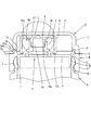
図1および2において、Aは容器、Bは容器Aに装着されるキャップ本体、Cはヒンジ、DはヒンジCを介してキャップ本体Bに連設された上蓋である。
容器Aは、口部1を有する容器であり、口部1の外周面には、嵌合突条2が設けられている。
1 and 2, A is a container, B is a cap main body mounted on the container A, C is a hinge, and D is an upper lid connected to the cap main body B via the hinge C.
The container A is a container having a
キャップ本体Bは、容器Aの口部1に装着する装着部3と、装着部3の上端から内方に延設され口部1の開口を封鎖する上壁4と、上壁4から立設される注出筒5とからなり、装着部3は、周縁に係止突条を設けた蓋係合部6を立設した環状の基壁7と、基壁7の内周縁から垂設された内筒8と、基壁7の外周縁から垂設された外筒9とからなっている。
外筒9の内周面下端部には、容器Aの口部1の嵌合突条2と係合する係合突条10が設けられている。
The cap body B has a mounting portion 3 to be mounted on the
An
上壁4の内方には、ヒンジCと反対側寄りを貫通する注出孔Fが形成され、注出孔Fの周囲から注出筒5が立設されている。
注出筒5の内周は、下部が縮径され、突条段部5aが設けられ、突条段部5aの断面形状は、上方が段状に形成されるとともに、下方が外方に向けてカーブして形成されており、口部1からの内容物の流れを妨げないで、スムーズに流れるようにしている。
注出筒5は、液状の内容物を案内するために、本実施例では、ヒンジC側が低く、ヒンジCと反対側が高く形成され、その先端部5bは、ラッパ状に広がっている。
On the inner side of the
The inner circumference of the
In order to guide the liquid contents, the dispensing
上蓋Dは、ヒンジCを介してキャップ本体Bの外筒9の外周上端に、回動自在に取着されており、頂壁11と、頂壁11の周縁部に垂設される側壁12とからなり、頂壁11の内面から、注出筒5より大径の筒壁13が垂設されている。
本実施例では、筒壁13の内径は、注出筒5の外径に比べて2倍程度となっているが、筒壁13の内径は、注出筒5の先端部5bと干渉しない範囲内で、必要に応じて設定可能である。
さらに、筒壁13の下端部13bは、キャップ本体Bの上壁4の上面と近接または当接するように設定されているが、筒壁13は、係止部13aを形成できる寸法を確保できれば、必ずしも上壁4の上面に届くまで延ばす必要はない。
The top lid D is pivotally attached to the outer peripheral upper end of the
In the present embodiment, the inner diameter of the
Furthermore, although the
筒壁13の内周には栓体Eを所定の範囲で上下動可能に保持するための係止部13aが周方向に設けられ、図4に示すように、係止部13aの断面形状は、上部の傾斜が急で、下部の傾斜が緩やかに形成されており、栓体Eを下方から挿入し易くするとともに、一旦挿入された栓体Eを抜け難く保持できるようになっている。
なお、係止部13aは、筒壁13の全内周にわたり形成されていても、または間隔をおいて形成されていても構わない。
側壁12の下端部内周には、キャップ本体Bの蓋係合部6の内周側と係合する凸部14と、蓋係合部6の外周側と係合する下方に係合突条を設けた係合凹部15とが形成されている。
側壁12のヒンジCと反対側の下端部外周には、摘み部16が円弧状に形成され、本実施例では、側壁12は、摘み部16が設けられた近傍を薄肉状部12aとし、摘み部16には、側壁12下端部近傍の上面に凹部16aが形成されている。
On the inner periphery of the
In addition, the latching | locking
On the inner periphery of the lower end portion of the
A
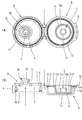
図1および4に示すように、栓体Eは、閉蓋時に注出筒5を密封状態とするもので、キャップ本体Bおよび上蓋Dとは別体の部材として構成されている。
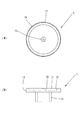
図5に示すように、栓体Eは、円盤状の栓体基部17と、栓体基部17の下面から垂設され、キャップ本体Bの注出筒5の内周に先端部18aから嵌入する密封リング18とから構成されている。
本実施例では、栓体基部17の外周上端部には、テーパー面が形成され、栓体Eを筒壁13の内側に挿入する際に、係止部13aの前述した緩やかな傾斜を乗り越え易くしている。
As shown in FIGS. 1 and 4, the plug E is used to seal the
As shown in FIG. 5, the plug E is suspended from the disc-
In the present embodiment, a tapered surface is formed on the upper end of the outer periphery of the
栓体基部17の上面周縁部および上面中央部には、それぞれ周縁突出部19および中央突出部20が形成され、図4(a)に示すように、閉蓋状態では、周縁突出部19の上面は、上蓋Dの頂壁11の内面と当接しているが、中央突出部20の上面は、頂壁11の内面とわずかに隙間を形成して近接している。
このため、閉蓋時に、栓体基部17の上面と頂壁11の内面との間には、周縁突出部19で囲まれる上方空隙21が形成される。
閉蓋時に、栓体Eの上面は、頂壁11の内面と当接すると、上蓋Dの筒壁13の内周面と栓体基部17の外周面との間に側方間隙S1が形成され、また、筒壁13の係止部13aの上端と栓体基部17の下面との間にも上下間隙S2が形成される。
これらの間隙S1およびS2が形成されることにより、栓体Eは、上蓋Dの筒壁13の内側で上下左右方向のガタ付きをもって保持される。
A
For this reason, the upper space |
When the lid is closed, when the upper surface of the plug E comes into contact with the inner surface of the
By forming these gaps S1 and S2, the plug E is held with back and forth in the vertical and horizontal directions inside the
次に、本実施例の使用態様と作用効果について説明する。
本実施例のヒンジキャップは、上蓋Dの筒壁13に栓体Eを組み付けるに当たって、上蓋Dを開いた状態で、キャップ本体Bの注出筒5の内周に栓体Eの密封リング18の先端部18aを嵌入し、ついで、ヒンジCを回動中心として、上蓋Dを閉じていくと、栓体基部17に筒壁13が被さり、さらに上蓋Dを閉じていくと、栓体基部17の外周面は、筒壁13内周の係止部13aを乗り越えて、筒壁13に保持される。
つぎに、図1に示すように、キャップ本体Bに対して上蓋Dを閉じた状態で、内容物が充填された容器Aの口部1に打栓して装着される。
打栓工程は、装着部3の内筒8と外筒9との間に形成された環状溝部に容器Aの口部1を当てがい、上蓋Dの上から押圧力が加えられ、外筒9の係合突条10が口部1の嵌合突条2を乗り越えて嵌合し、容器Aの口部1が内筒8の外周と外筒9の内周、および基壁7とによって挟持されることで装着される。
Next, usage modes and operational effects of this embodiment will be described.
The hinge cap according to the present embodiment has the sealing
Next, as shown in FIG. 1, the cap body B is plugged into the
In the plugging step, the
打栓工程において、上蓋Dの上から押圧力が加えられると、頂壁11が下向きに変形されるが、本実施例では、筒壁13の下端部13bは、キャップ本体Bの上壁4の上面と近接または当接しているので、頂壁11が変形して下端部13bは、上壁4に当接して、それ以上の変形を阻止することができる。
さらに、栓体Eの密封リング18の先端部18aは、注出筒5の突条段部5aと近接または当接しているので、頂壁11に下向きの力が加わると、先端部18aは、突条段部5aと当接して、それ以上密封リング18が注出筒5の内周に食い込むのを阻止することができ、密封リング18と注出筒5とによる良好なシールを維持することができる。仮に、注出筒5に突条段部5aが設けられていないと、密封リング18は、注出筒5の内周に押し込められて、注出筒5とのシールを損なうことになる。
この際に、密封リング18の先端部18aは、突条段部5aとわずかな間隙を保って近接していることが好ましく、この間隙は、0.1〜0.5mmが特に好ましい。
なお、本実施例では、装着部3は、内筒8の外周と外筒9の内周、および基壁7とによって容器Aの口部1を狭持するものとしたが、容器Aの口部1の外周に雄ネジを形成するとともに、外筒9の内周に雌ネジを形成することによって螺着するものであってもよい。
In the plugging process, when a pressing force is applied from above the upper lid D, the
Furthermore, since the
At this time, the
In the present embodiment, the mounting portion 3 holds the
上述したように、閉蓋状態では、密封リング18が注出筒5の内周に嵌入することによって栓体Eは、キャップ本体Bの注出筒5と一体化されており、容器Aの転倒時あるいは落下等の衝撃により、図3および図4の(b)で示すように、上蓋Dに外力が加わり、上蓋Dに上下あるいは左右方向のずれが生じた場合でも、栓体Eには、筒壁13内周および頂壁11内面に対して、それぞれ側方間隙S1および上下間隙S2が形成されることにより、上蓋Dの動きに対する影響が緩和され、容器Aの気密性を保つことができる。
また、栓体Eは、栓体基部17の上面に上方空隙21が形成され、栓体基部17の周縁突出部19および中央突出部20を除き薄肉になっていることにより、栓体基部17は、上蓋Dから力を受けた際に、変形することで密封筒18に加わる力を分散することができる。
さらに、栓体基部17の中央突出部20は、容器Aの転倒時あるいは落下時に、上蓋Dの頂壁11から栓体Eに加わる力をピンポイントで受け止めることにより、衝撃力を緩和することができる。
本実施例では、周縁突出部19は、図5(a)に示すように、栓体基部17の上面周縁部全周にわたり形成されているが、間欠的に形成されていても構わないし、また、中央突出部20は、栓体基部17の上面中央部に1箇所だけ形成されているが、中央部の周辺に複数、均等に配置するように形成されても構わない。
また、打栓工程で説明したように、栓体Eの密封リング18は、先端部18aが注出筒5の突条段部5aとわずかな間隙を保って近接していることと相まって、密封リング18を垂設する栓体基部17は、上方空隙21が形成される部分で変形し易くなっていることにより、容器Aの転倒時あるいは落下時に、上蓋Dが変形しても、栓体基部17の上方空隙21が形成される部分が変形するだけで、密封リング18自体は変形しないで、先端部18aが、わずかに下降して突条段部5aと当接し、それ以上の下降が停止することにより、密封リング18と注出筒5の内周とのシールを維持することができる。
As described above, in the closed state, the sealing
Further, the plug body E has an
Further, the central projecting
In the present embodiment, the
Further, as described in the plugging process, the sealing
本実施例のキャップを開封するには、図1に示す状態から、図3のように、上蓋Dの摘み部16を押し上げ、上蓋Dの係合凹部15とキャップ本体Bの蓋係合部6との係合を解除し、さらに、摘み部16を上方に持ち上げると、上蓋Dの筒壁13が上昇して係止部13aが栓体基部17の外縁部に当接して持ち上げられ、キャップ本体Bの注出筒5から密封リング18を外すことができ、図2に示す開蓋状態となる。
本実施例では、抜栓作業なしに、閉蓋状態から上蓋Dの摘み部16を持ち上げ、上蓋Dとともに、それに連動する栓体Eの密封リング18がキャップ本体Bの注出筒5から外されれば、容器Aを傾けただけで、容易に注出筒5から容器A内の内容物を注出することができる。
To open the cap of the present embodiment, as shown in FIG. 3, the
In this embodiment, without removing the plug, the
つぎに、容器Aの使用を終えた後、上蓋Dを閉じると、栓体Eの密封リング18が注出筒5の内周に嵌入し、栓体Eをキャップ本体Bの注出筒5と一体化させた後、側壁12の凸部14と係合凹部15がキャップ本体Bの蓋係合部6を挟むように嵌合して、閉蓋状態に戻る。
この際に、上蓋Dは、凸部14と係合凹部15がキャップ本体Bの蓋係合部6を挟むことになり、転倒時あるいは落下時に上蓋Dに力が加わっても、側壁12の下端部がずれて変形するのを阻止することができる。
このように、何度でも注出筒5を密封可能なヒンジキャップが得られ、閉蓋状態では、栓体Eは、キャップ本体Bと一体化し、転倒あるいは落下等によって、上蓋Dに力がかかった場合でも、容器A内の気密性を保つことができるという優れた効果を奏する。
なお、注出筒5の位置は、キャップ本体Bの上壁4の中央でなくても、適宜変えることが可能であり、どちらかというとヒンジCと反対側の方に偏心させた方が、注出筒5から内容物を注出するのに都合がよい。
Next, after the use of the container A is finished, when the upper lid D is closed, the sealing
At this time, in the upper lid D, the
In this way, a hinge cap capable of sealing the
The position of the
また、ヒンジキャップ全体を同一の合成樹脂製としてもよいが、栓体Eをキャップ本体B及び上蓋Dの合成樹脂より、硬質の合成樹脂とした場合、栓体Eを注出筒5の内周に嵌入しやすくなり、気密性が向上する。
さらに、容器Aについては、どのような材質のものでもよく、また、容器内に収納する内容物も液状に限らず、粉末状、顆粒状などでもかまわない。
本発明によれば、容器内の内容物を長期にわたって気密に保つことができる。
The entire hinge cap may be made of the same synthetic resin. However, when the plug body E is made of a synthetic resin harder than the synthetic resin of the cap body B and the upper lid D, the plug body E is the inner periphery of the
Further, the container A may be made of any material, and the contents stored in the container are not limited to liquid, and may be powdered or granular.
According to the present invention, the contents in the container can be kept airtight for a long time.
本発明のヒンジキャップは、キャップ本体および上蓋と別体に構成した栓体を備え、栓体の密封リングをキャップ本体の注出筒に嵌入して一体化させ、容器が密封されることにより、転倒あるいは落下などにより、上蓋に力がかかったときにも、栓体には影響しない構造を有しているため、容器の気密性を保つことができる。また、何度でも開閉が容易で、しかもリシール性がよいため、内容物としては、液状の洗浄料、食品、調味料だけでなく、粉末状のものにも適用可能であり、特に気密性の必要な内容物を収納する容器として好適である。 The hinge cap of the present invention is provided with a cap body that is configured separately from the cap body and the upper lid, and the sealing ring of the plug body is integrated by being fitted into the extraction cylinder of the cap body, whereby the container is sealed, Even when force is applied to the upper lid due to falling or dropping, the container has a structure that does not affect the stopper, so that the airtightness of the container can be maintained. In addition, since it can be easily opened and closed many times and has good resealability, the contents can be applied not only to liquid cleaning materials, foods, seasonings, but also to powdered materials, especially airtight. It is suitable as a container for storing necessary contents.
A 容器
B キャップ本体
C ヒンジ
D 上蓋
E 栓体
F 注出孔
S1 側方間隙
S2 上下間隙
1 口部
2 嵌合突条
3 装着部
4 上壁
5 注出筒
5a 突条段部
5b 先端部
6 蓋係合部
7 基壁
8 内筒
9 外筒
10 係合突条
11 頂壁
12 側壁
12a 薄肉状部
13 筒壁
13a 係止部
13b 下端部
14 凸部
15 係合凹部
16 摘み部
16a 凹部
17 栓体基部
18 密封リング
18a 先端部
19 周縁突出部
20 中央突出部
21 上方空隙
A Container B Cap body C Hinge D Upper lid E Plug body F Outlet S1 Side gap
Claims (4)
キャップ本体は、容器の口部に装着する装着部と、装着部上端から内方に延設され口部開口を封鎖する上壁と、上壁を貫通する注出孔の周囲に立設される注出筒とを備え、
上蓋は、頂壁と、頂壁の周縁部に垂設される側壁と、頂壁の内面から垂設される筒壁と、筒壁の内側で上下動可能に保持される栓体とを備え、
栓体は、注出筒内周を密封する密封リングを有し、
注出筒は、内周下部に、密封リングの先端部と近接または当接する突条段部を有することを特徴とするヒンジキャップ。 A hinge cap comprising a cap body attached to the mouth of the container, and an upper lid connected to the cap body via a hinge,
The cap body is erected around a mounting portion to be mounted on the mouth portion of the container, an upper wall extending inward from the upper end of the mounting portion and sealing the opening of the mouth portion, and a pouring hole penetrating the upper wall. With a dispensing tube,
The upper lid includes a top wall, a side wall suspended from the periphery of the top wall, a cylindrical wall suspended from the inner surface of the top wall, and a plug body that is held up and down inside the cylindrical wall. ,
The plug has a sealing ring that seals the inner periphery of the dispensing cylinder,
2. The hinge cap according to claim 1, wherein the dispensing tube has a protrusion step portion adjacent to or in contact with the tip end portion of the sealing ring at a lower portion of the inner periphery.
栓体基部は、上面に上方空隙を形成する周縁突出部を有することを特徴とする請求項1または2に記載のヒンジキャップ。 The plug has a disc-shaped plug base that hangs a sealing ring from the lower surface,
The hinge cap according to claim 1 or 2, wherein the plug base has a peripheral protrusion that forms an upper gap on the upper surface.
Priority Applications (1)
| Application Number | Priority Date | Filing Date | Title |
|---|---|---|---|
| JP2015131482A JP6529363B2 (en) | 2015-06-30 | 2015-06-30 | Hinge cap |
Applications Claiming Priority (1)
| Application Number | Priority Date | Filing Date | Title |
|---|---|---|---|
| JP2015131482A JP6529363B2 (en) | 2015-06-30 | 2015-06-30 | Hinge cap |
Publications (2)
| Publication Number | Publication Date |
|---|---|
| JP2017013830A true JP2017013830A (en) | 2017-01-19 |
| JP6529363B2 JP6529363B2 (en) | 2019-06-12 |
Family
ID=57828942
Family Applications (1)
| Application Number | Title | Priority Date | Filing Date |
|---|---|---|---|
| JP2015131482A Active JP6529363B2 (en) | 2015-06-30 | 2015-06-30 | Hinge cap |
Country Status (1)
| Country | Link |
|---|---|
| JP (1) | JP6529363B2 (en) |
Cited By (6)
| Publication number | Priority date | Publication date | Assignee | Title |
|---|---|---|---|---|
| JP2019077469A (en) * | 2017-10-25 | 2019-05-23 | 三笠産業株式会社 | cap |
| JP2019189324A (en) * | 2018-04-27 | 2019-10-31 | 株式会社吉野工業所 | Hinge cap |
| JP2020019521A (en) * | 2018-07-31 | 2020-02-06 | 株式会社吉野工業所 | Hinge cap |
| JP2020055566A (en) * | 2018-09-28 | 2020-04-09 | 株式会社吉野工業所 | Cap sealing structure |
| JP2020164201A (en) * | 2019-03-29 | 2020-10-08 | 株式会社吉野工業所 | cap |
| JP7401237B2 (en) | 2019-09-26 | 2023-12-19 | 日本クロージャー株式会社 | container lid |
Citations (6)
| Publication number | Priority date | Publication date | Assignee | Title |
|---|---|---|---|---|
| JPS5125048U (en) * | 1974-08-14 | 1976-02-24 | ||
| JPH0542162U (en) * | 1991-10-31 | 1993-06-08 | 大和製罐株式会社 | Hinge cap |
| JP2002002760A (en) * | 2000-06-16 | 2002-01-09 | Toyo Seikan Kaisha Ltd | Liquid dropping preventing pour cap |
| JP2015006912A (en) * | 2013-05-29 | 2015-01-15 | 株式会社吉野工業所 | Hinge cap |
| JP2015009865A (en) * | 2013-06-29 | 2015-01-19 | 株式会社打田製作所 | Packaging member and container including the same |
| JP2015107815A (en) * | 2013-12-05 | 2015-06-11 | 三笠産業株式会社 | Cap |
-
2015
- 2015-06-30 JP JP2015131482A patent/JP6529363B2/en active Active
Patent Citations (6)
| Publication number | Priority date | Publication date | Assignee | Title |
|---|---|---|---|---|
| JPS5125048U (en) * | 1974-08-14 | 1976-02-24 | ||
| JPH0542162U (en) * | 1991-10-31 | 1993-06-08 | 大和製罐株式会社 | Hinge cap |
| JP2002002760A (en) * | 2000-06-16 | 2002-01-09 | Toyo Seikan Kaisha Ltd | Liquid dropping preventing pour cap |
| JP2015006912A (en) * | 2013-05-29 | 2015-01-15 | 株式会社吉野工業所 | Hinge cap |
| JP2015009865A (en) * | 2013-06-29 | 2015-01-19 | 株式会社打田製作所 | Packaging member and container including the same |
| JP2015107815A (en) * | 2013-12-05 | 2015-06-11 | 三笠産業株式会社 | Cap |
Cited By (11)
| Publication number | Priority date | Publication date | Assignee | Title |
|---|---|---|---|---|
| JP2019077469A (en) * | 2017-10-25 | 2019-05-23 | 三笠産業株式会社 | cap |
| JP7054504B2 (en) | 2017-10-25 | 2022-04-14 | 三笠産業株式会社 | cap |
| JP2019189324A (en) * | 2018-04-27 | 2019-10-31 | 株式会社吉野工業所 | Hinge cap |
| JP7178795B2 (en) | 2018-04-27 | 2022-11-28 | 株式会社吉野工業所 | hinge cap |
| JP2020019521A (en) * | 2018-07-31 | 2020-02-06 | 株式会社吉野工業所 | Hinge cap |
| JP7010788B2 (en) | 2018-07-31 | 2022-01-26 | 株式会社吉野工業所 | Hinge cap |
| JP2020055566A (en) * | 2018-09-28 | 2020-04-09 | 株式会社吉野工業所 | Cap sealing structure |
| JP7220950B2 (en) | 2018-09-28 | 2023-02-13 | 株式会社吉野工業所 | Cap seal structure |
| JP2020164201A (en) * | 2019-03-29 | 2020-10-08 | 株式会社吉野工業所 | cap |
| JP7229073B2 (en) | 2019-03-29 | 2023-02-27 | 株式会社吉野工業所 | cap |
| JP7401237B2 (en) | 2019-09-26 | 2023-12-19 | 日本クロージャー株式会社 | container lid |
Also Published As
| Publication number | Publication date |
|---|---|
| JP6529363B2 (en) | 2019-06-12 |
Similar Documents
| Publication | Publication Date | Title |
|---|---|---|
| JP2017013830A (en) | Hinge cap | |
| JP6942408B2 (en) | Unplug-less cap | |
| JP2015105132A (en) | Hinge cap | |
| JP5813580B2 (en) | Double container | |
| JP6831267B2 (en) | Refill container | |
| KR101385339B1 (en) | Vessel of cosmetics | |
| JP6859778B2 (en) | Cap sealing structure | |
| JP6108866B2 (en) | Hinge cap | |
| JP2007176577A (en) | Pouring cap | |
| JP5182811B2 (en) | Container with lid | |
| KR20070120007A (en) | Easy opening airtight container | |
| JP6576622B2 (en) | Dispensing container | |
| JP6602231B2 (en) | Hinge cap | |
| JP6314364B2 (en) | Container with lid | |
| JP6833279B2 (en) | Inner container with cap | |
| JP6478792B2 (en) | container | |
| JP7391501B2 (en) | hinge cap | |
| JP7178795B2 (en) | hinge cap | |
| JP7096748B2 (en) | Hinge cap | |
| JP6833286B2 (en) | Screw cap | |
| JP2017030808A (en) | Unplug mechanism of container | |
| JP2018090267A (en) | Hinge cap | |
| JP2014008977A (en) | Hinge cap | |
| JP2019131216A (en) | Hinge cap | |
| JP7278871B2 (en) | hinge cap |
Legal Events
| Date | Code | Title | Description |
|---|---|---|---|
| A621 | Written request for application examination |
Free format text: JAPANESE INTERMEDIATE CODE: A621 Effective date: 20180109 |
|
| A977 | Report on retrieval |
Free format text: JAPANESE INTERMEDIATE CODE: A971007 Effective date: 20181018 |
|
| A131 | Notification of reasons for refusal |
Free format text: JAPANESE INTERMEDIATE CODE: A131 Effective date: 20181023 |
|
| TRDD | Decision of grant or rejection written | ||
| A01 | Written decision to grant a patent or to grant a registration (utility model) |
Free format text: JAPANESE INTERMEDIATE CODE: A01 Effective date: 20190514 |
|
| A61 | First payment of annual fees (during grant procedure) |
Free format text: JAPANESE INTERMEDIATE CODE: A61 Effective date: 20190514 |
|
| R150 | Certificate of patent or registration of utility model |
Ref document number: 6529363 Country of ref document: JP Free format text: JAPANESE INTERMEDIATE CODE: R150 |