JP2017012381A - External ultrasonic probe - Google Patents
External ultrasonic probe Download PDFInfo
- Publication number
- JP2017012381A JP2017012381A JP2015131601A JP2015131601A JP2017012381A JP 2017012381 A JP2017012381 A JP 2017012381A JP 2015131601 A JP2015131601 A JP 2015131601A JP 2015131601 A JP2015131601 A JP 2015131601A JP 2017012381 A JP2017012381 A JP 2017012381A
- Authority
- JP
- Japan
- Prior art keywords
- vibration element
- width
- probe
- element group
- ultrasonic probe
- Prior art date
- Legal status (The legal status is an assumption and is not a legal conclusion. Google has not performed a legal analysis and makes no representation as to the accuracy of the status listed.)
- Granted
Links
- 239000000523 sample Substances 0.000 title claims abstract description 137
- 239000000463 material Substances 0.000 claims abstract description 69
- 229920000306 polymethylpentene Polymers 0.000 claims description 13
- 239000011116 polymethylpentene Substances 0.000 claims description 13
- 239000011248 coating agent Substances 0.000 claims description 5
- 238000000576 coating method Methods 0.000 claims description 5
- 239000000945 filler Substances 0.000 claims description 3
- 229920003002 synthetic resin Polymers 0.000 claims description 3
- 239000000057 synthetic resin Substances 0.000 claims description 3
- 229920001296 polysiloxane Polymers 0.000 claims 1
- 238000003384 imaging method Methods 0.000 description 18
- 210000004185 liver Anatomy 0.000 description 7
- 230000003601 intercostal effect Effects 0.000 description 6
- 239000013464 silicone adhesive Substances 0.000 description 6
- 229920002379 silicone rubber Polymers 0.000 description 6
- 239000004945 silicone rubber Substances 0.000 description 6
- XLYOFNOQVPJJNP-UHFFFAOYSA-N water Substances O XLYOFNOQVPJJNP-UHFFFAOYSA-N 0.000 description 6
- 238000000034 method Methods 0.000 description 5
- 238000002604 ultrasonography Methods 0.000 description 5
- 230000003187 abdominal effect Effects 0.000 description 4
- 239000004033 plastic Substances 0.000 description 4
- 239000000853 adhesive Substances 0.000 description 3
- 230000001070 adhesive effect Effects 0.000 description 3
- 238000010586 diagram Methods 0.000 description 3
- 230000000694 effects Effects 0.000 description 3
- 238000012285 ultrasound imaging Methods 0.000 description 3
- VYPSYNLAJGMNEJ-UHFFFAOYSA-N Silicium dioxide Chemical compound O=[Si]=O VYPSYNLAJGMNEJ-UHFFFAOYSA-N 0.000 description 2
- 230000002159 abnormal effect Effects 0.000 description 2
- 230000005856 abnormality Effects 0.000 description 2
- 230000003247 decreasing effect Effects 0.000 description 2
- 238000013461 design Methods 0.000 description 2
- 210000001835 viscera Anatomy 0.000 description 2
- 210000001015 abdomen Anatomy 0.000 description 1
- 230000001154 acute effect Effects 0.000 description 1
- 230000005540 biological transmission Effects 0.000 description 1
- 238000004891 communication Methods 0.000 description 1
- 238000007796 conventional method Methods 0.000 description 1
- -1 for example Polymers 0.000 description 1
- 230000005484 gravity Effects 0.000 description 1
- 238000002156 mixing Methods 0.000 description 1
- 238000012986 modification Methods 0.000 description 1
- 230000004048 modification Effects 0.000 description 1
- 238000000465 moulding Methods 0.000 description 1
- 238000003825 pressing Methods 0.000 description 1
- 230000001902 propagating effect Effects 0.000 description 1
- 230000035945 sensitivity Effects 0.000 description 1
- 230000035939 shock Effects 0.000 description 1
- 239000000377 silicon dioxide Substances 0.000 description 1
- 210000004872 soft tissue Anatomy 0.000 description 1
Images


Classifications
-
- A—HUMAN NECESSITIES
- A61—MEDICAL OR VETERINARY SCIENCE; HYGIENE
- A61B—DIAGNOSIS; SURGERY; IDENTIFICATION
- A61B8/00—Diagnosis using ultrasonic, sonic or infrasonic waves
- A61B8/44—Constructional features of the ultrasonic, sonic or infrasonic diagnostic device
- A61B8/4483—Constructional features of the ultrasonic, sonic or infrasonic diagnostic device characterised by features of the ultrasound transducer
- A61B8/4494—Constructional features of the ultrasonic, sonic or infrasonic diagnostic device characterised by features of the ultrasound transducer characterised by the arrangement of the transducer elements
-
- A—HUMAN NECESSITIES
- A61—MEDICAL OR VETERINARY SCIENCE; HYGIENE
- A61B—DIAGNOSIS; SURGERY; IDENTIFICATION
- A61B8/00—Diagnosis using ultrasonic, sonic or infrasonic waves
- A61B8/42—Details of probe positioning or probe attachment to the patient
- A61B8/4272—Details of probe positioning or probe attachment to the patient involving the acoustic interface between the transducer and the tissue
- A61B8/4281—Details of probe positioning or probe attachment to the patient involving the acoustic interface between the transducer and the tissue characterised by sound-transmitting media or devices for coupling the transducer to the tissue
-
- A—HUMAN NECESSITIES
- A61—MEDICAL OR VETERINARY SCIENCE; HYGIENE
- A61B—DIAGNOSIS; SURGERY; IDENTIFICATION
- A61B8/00—Diagnosis using ultrasonic, sonic or infrasonic waves
- A61B8/44—Constructional features of the ultrasonic, sonic or infrasonic diagnostic device
- A61B8/4427—Device being portable or laptop-like
-
- A—HUMAN NECESSITIES
- A61—MEDICAL OR VETERINARY SCIENCE; HYGIENE
- A61B—DIAGNOSIS; SURGERY; IDENTIFICATION
- A61B8/00—Diagnosis using ultrasonic, sonic or infrasonic waves
- A61B8/44—Constructional features of the ultrasonic, sonic or infrasonic diagnostic device
- A61B8/4444—Constructional features of the ultrasonic, sonic or infrasonic diagnostic device related to the probe
-
- B—PERFORMING OPERATIONS; TRANSPORTING
- B06—GENERATING OR TRANSMITTING MECHANICAL VIBRATIONS IN GENERAL
- B06B—METHODS OR APPARATUS FOR GENERATING OR TRANSMITTING MECHANICAL VIBRATIONS OF INFRASONIC, SONIC, OR ULTRASONIC FREQUENCY, e.g. FOR PERFORMING MECHANICAL WORK IN GENERAL
- B06B1/00—Methods or apparatus for generating mechanical vibrations of infrasonic, sonic, or ultrasonic frequency
- B06B1/02—Methods or apparatus for generating mechanical vibrations of infrasonic, sonic, or ultrasonic frequency making use of electrical energy
- B06B1/06—Methods or apparatus for generating mechanical vibrations of infrasonic, sonic, or ultrasonic frequency making use of electrical energy operating with piezoelectric effect or with electrostriction
- B06B1/0644—Methods or apparatus for generating mechanical vibrations of infrasonic, sonic, or ultrasonic frequency making use of electrical energy operating with piezoelectric effect or with electrostriction using a single piezoelectric element
- B06B1/0662—Methods or apparatus for generating mechanical vibrations of infrasonic, sonic, or ultrasonic frequency making use of electrical energy operating with piezoelectric effect or with electrostriction using a single piezoelectric element with an electrode on the sensitive surface
- B06B1/067—Methods or apparatus for generating mechanical vibrations of infrasonic, sonic, or ultrasonic frequency making use of electrical energy operating with piezoelectric effect or with electrostriction using a single piezoelectric element with an electrode on the sensitive surface which is used as, or combined with, an impedance matching layer
-
- A—HUMAN NECESSITIES
- A61—MEDICAL OR VETERINARY SCIENCE; HYGIENE
- A61B—DIAGNOSIS; SURGERY; IDENTIFICATION
- A61B8/00—Diagnosis using ultrasonic, sonic or infrasonic waves
- A61B8/44—Constructional features of the ultrasonic, sonic or infrasonic diagnostic device
- A61B8/4444—Constructional features of the ultrasonic, sonic or infrasonic diagnostic device related to the probe
- A61B8/4472—Wireless probes
Abstract
Description
本発明の一態様としての本実施形態は、超音波を送受信する体外式超音波プローブに関する。 The present embodiment as one aspect of the present invention relates to an external ultrasonic probe that transmits and receives ultrasonic waves.
一般的に、超音波診断装置に接続して用いられる超音波プローブには、1方向(アジマス方向)に複数の振動素子が配列された1次元アレイプローブ(1Dプローブ)や、2方向(アジマス方向およびエレベーション方向)に複数の振動素子が配列され、当該2方向に電子的に超音波ビームを振ることができる2次元アレイプローブ(2Dプローブ)や、当該2方向に複数の振動素子が配列されているものの、エレベーション方向に超音波ビームを振ることができない多列アレイプローブ(1.5Dプローブ)が挙げられる。 Generally, an ultrasonic probe connected to an ultrasonic diagnostic apparatus is a one-dimensional array probe (1D probe) in which a plurality of vibration elements are arranged in one direction (azimuth direction) or two directions (azimuth direction). And a plurality of vibration elements are arranged in the two directions and a two-dimensional array probe (2D probe) capable of electronically oscillating an ultrasonic beam in the two directions. However, there is a multi-row array probe (1.5D probe) that cannot oscillate an ultrasonic beam in the elevation direction.
アレイ型の超音波プローブのうち、1D及び1.5Dプローブは、走査面に沿って超音波ビームを収束し、薄い断層面を得るための音響レンズを備える。音響レンズとしては、音速が体表及び生体(軟部組織)と異なり、かつ、音響インピーダンスが体表及び生体に近い材料が用いられることが要求される。これらの要求を満たす材料として、生体に比べて音速が遅い材料であるシリコーンゴムや、生体に比べて音速が速い材料であるポリメチルペンテンが知られている。 Among array-type ultrasonic probes, 1D and 1.5D probes are provided with an acoustic lens for focusing an ultrasonic beam along a scanning plane to obtain a thin tomographic plane. As an acoustic lens, it is required to use a material whose sound velocity is different from that of the body surface and the living body (soft tissue) and whose acoustic impedance is close to that of the body surface and the living body. As materials that satisfy these requirements, silicone rubber, which is a material having a slower sound speed than that of a living body, and polymethylpentene, which is a material having a faster sound speed than that of a living body, are known.
シリコーンゴム製の音響レンズが用いられる場合、音響レンズとポリメチルペンテン(プラスティック)製の側面被覆材とは、一般的にはシリコーン接着剤で接着され、防水性を保持される。しかし、シリコーン接着剤自体の剛性が低く、プラスティック材料に対する接着力も低いので、信頼性維持のため一定の接着面積が必要である。そのため、接着面積の分だけ超音波プローブの生体接触面の幅(厚み)が大きくなる。 When an acoustic lens made of silicone rubber is used, the acoustic lens and the side covering material made of polymethylpentene (plastic) are generally bonded with a silicone adhesive to maintain waterproofness. However, since the rigidity of the silicone adhesive itself is low and the adhesive force to the plastic material is low, a certain adhesion area is required for maintaining reliability. For this reason, the width (thickness) of the living body contact surface of the ultrasonic probe is increased by an amount corresponding to the adhesion area.
また、ポリメチルペンテン製の音響レンズが用いられる場合、音響媒体を保持するための構造体(水袋)が必要となるので、やはり超音波プローブの生体接触面の幅は大きくなる。 Further, when an acoustic lens made of polymethylpentene is used, a structure (water bag) for holding the acoustic medium is required, so that the width of the biological contact surface of the ultrasonic probe is also increased.
従来の超音波プローブが用いられて体表から体内(心臓や肝臓などの胸部内蔵)の超音波撮影が行なわれる場合、胸部内蔵が肋骨で覆われた領域に位置するので、肋間からのスキャンが必須である。特に肝臓の超音波撮影時、異常部位が存在するかどうか分からない状況での走査においては、肋骨裏の領域に死角が生じると、異常の見落としにつながる。 When a conventional ultrasound probe is used to perform ultrasound imaging of the inside of the body (with built-in chest such as heart and liver) from the body surface, the built-in chest is located in an area covered with ribs, so scanning from the intercostal space It is essential. In particular, during ultrasound imaging of the liver, in a scan in a situation where it is not known whether an abnormal site exists, if a blind spot occurs in the area behind the ribs, it leads to an oversight of the abnormality.
従来の超音波プローブを用いて肋骨裏の走査を行なうためには、操作者は、体表から肋間に超音波プローブを当て、超音波プローブを傾ける操作を行なう。ところが、超音波プローブの生体接触面の幅が大きいと、操作者はより大きな角度となるように超音波プローブを傾けると、撮影領域が肋間から外れてしまう。超音波プローブを大きく傾けながら肋間を撮影領域とする操作は不可能であり、肋骨裏に死角が生じる。加えて、操作者が、死角を狭めようと超音波プローブを患者に深く押しつけて超音波撮影を行なおうとすると、超音波プローブを押し付けられる患者の負担が大きくなる。 In order to scan the back of the rib using a conventional ultrasonic probe, the operator applies an ultrasonic probe between the body surface and the heel and tilts the ultrasonic probe. However, if the width of the living body contact surface of the ultrasonic probe is large, if the operator tilts the ultrasonic probe so as to have a larger angle, the imaging region will be out of the gap. It is impossible to operate the space between the ribs while the ultrasonic probe is greatly tilted, and a blind spot is formed behind the ribs. In addition, when an operator tries to perform ultrasound imaging by pressing the ultrasound probe deeply against the patient to narrow the blind spot, the burden on the patient who can press the ultrasound probe increases.
また、音響レンズの材料であるシリコーンゴムは柔軟性であり、超音波プローブを床面に誤って落下させた場合や他の機器にぶつけた場合などに、音響レンズが受ける衝撃が振動素子に伝搬することで振動素子の故障の原因となる。 Silicone rubber, which is the material of the acoustic lens, is flexible, and the shock received by the acoustic lens propagates to the vibration element when the ultrasonic probe is accidentally dropped on the floor surface or hit against other equipment. Doing so causes a failure of the vibration element.
本実施形態に係る体外式超音波プローブは、上述した課題を解決するために、アジマス方向に沿って配置され、超音波を送受する振動素子群と、生体に接触可能な凸面を有し、単一の部材で形成され、前記振動素子群の正面側を全体的に被覆し、前記振動素子群の側面側の少なくとも一部を被覆する被覆材と、を備え、前記アジマス方向における前記振動素子群の幅を略二等分する断面において、前記凸面の頂点から2[mm]落ち込んだ前記凸面上の2点間の幅は、エレベーション方向における前記振動子群の幅より大きく、前記2点間の幅と前記エレベーション方向における前記振動子群の幅の差は5[mm]以下である。 In order to solve the above-described problem, the extracorporeal ultrasonic probe according to the present embodiment is arranged along the azimuth direction, has a vibration element group that transmits and receives ultrasonic waves, a convex surface that can contact a living body, And a covering material that covers the entire front side of the vibration element group and covers at least a part of the side surface of the vibration element group, the vibration element group in the azimuth direction. In a cross-section that bisects the width of the convex surface, the width between the two points on the convex surface that is 2 [mm] lower than the vertex of the convex surface is larger than the width of the transducer group in the elevation direction, and the distance between the two points And the width of the transducer group in the elevation direction is 5 [mm] or less.
本実施形態に係る体外式超音波プローブは、上述した課題を解決するために、アジマス方向に沿って配置され、超音波を送受する振動素子群と、生体に接触可能な凸面を有し、単一の部材で形成され、前記振動素子群の正面側を全体的に被覆し、前記振動素子群の側面側の少なくとも一部を被覆する被覆材と、を備え、前記エレベーション方向における前記振動素子群の幅は6〜12[mm]である。 In order to solve the above-described problem, the extracorporeal ultrasonic probe according to the present embodiment is arranged along the azimuth direction, has a vibration element group that transmits and receives ultrasonic waves, a convex surface that can contact a living body, And a covering material that covers the entire front side of the vibration element group and covers at least a part of the side surface of the vibration element group, the vibration element in the elevation direction. The width of the group is 6 to 12 [mm].
本実施形態に係る体外式超音波プローブについて、添付図面を参照して説明する。 The extracorporeal ultrasonic probe according to this embodiment will be described with reference to the accompanying drawings.
図1は、本実施形態に係る体外式超音波プローブ及び超音波診断装置の構成を示す概略図である。 FIG. 1 is a schematic diagram illustrating the configuration of an extracorporeal ultrasonic probe and an ultrasonic diagnostic apparatus according to the present embodiment.
図1は、本実施形態に係る体外式超音波プローブ(体表プローブ)10と、超音波診断装置41とを示す。なお、体外式超音波プローブ10を含めて超音波診断装置と称する場合もある。
FIG. 1 shows an external ultrasonic probe (body surface probe) 10 and an ultrasonic
体外式超音波プローブ10は、体表よりアプローチし、体内の臓器などの形態を画像化する場合に用いられる。以下、体外式超音波プローブを、単に「プローブ」という。
The extracorporeal
プローブ10は、超音波診断装置41による制御に従って、生体に対して超音波の送受波を行なう。プローブ10は、図5に示すように、振動素子11、バッキング材12、及び被覆材17などを備える。振動素子11は、図5に示すように、圧電素子21、音響整合層221,222を備える。なお、例えば、振動素子11は、圧電素子21を除く上記構成のいずれかを備えていなくても良く、圧電素子21とバッキング材12との間に位置する図示しないハードバック層などの構成を追加的に備えていても良い。プローブ10の振動素子11を構成する圧電素子21は、電気音響変換素子であり、送信時には電気信号を超音波(送信超音波)に変換し、又、受信時には超音波反射波(受信超音波)を電気信号(受信信号)に変換する機能を有する。
The
複数の振動素子11は、第1方向(アジマス方向)D1に沿って1次元的に配列され、振動素子群を形成する。この場合、プローブ10は、1Dプローブである。
The plurality of
又は、振動素子11は、第1方向D1及び第2方向(エレベーション方向)D2に沿って2次元的に配列され、振動素子群を形成する。この場合、本実施形態におけるプローブ10は、第2方向に超音波ビームを振ることができない、1.5Dプローブである。
Alternatively, the
プローブ10は小型、軽量に構成されており、ケーブル42を介して超音波診断装置41に接続される。プローブ10にはセクタ走査型、リニア走査型、及びコンベックス走査型などがあり、診断部位に応じて任意に選択される。プローブ10の具体的な構造については図5及び図6を用いて後述する。なお、プローブ10は、無線通信を利用して、超音波診断装置41に信号を出力しても良い。
The
超音波診断装置41は、プローブ10の動作を制御し、プローブ10の圧電素子21を駆動するための駆動パルスをプローブ10に送信する。また、超音波診断装置41は、プローブ10の動作を制御し、プローブ10の圧電素子21で変換された電気的な受信信号を受信してBモード画像などの超音波画像を生成する。
The ultrasonic
続いて、図2〜図4を用いて、従来のプローブについて説明する。 Next, a conventional probe will be described with reference to FIGS.
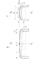
図2及び図3は、従来のプローブの先端部分の構造を示す断面図である。具体的には、プローブ50が有する振動素子群の第1方向(アジマス方向)における幅を略二等分する断面の断面図である。
2 and 3 are cross-sectional views showing the structure of the tip portion of a conventional probe. Specifically, it is a cross-sectional view of a cross section that bisects the width in the first direction (azimuth direction) of the vibration element group included in the
プローブ50は、振動素子51、バッキング材52、第3音響整合層53、グランド(GND)リード54、信号線55、側面被覆材56、及び音響レンズ57を備える。
The
振動素子51は、圧電素子61、第1音響整合層621、及び第2音響整合層622を備える。
The
側面被覆材56は、ポリメチルペンテン(プラスティック)を材料とし、振動素子51の側面側を被覆する。
The side
音響レンズ57は、シリコーンゴムを材料とし、生体に接触可能な凸面を有する。音響レンズ57は振動素子で発生した超音波の第2方向(エレベーション方向)D2に関する収束に寄与する。また、音響レンズ57は、振動素子51の正面側の大半又は全体を被覆する。
The
側面被覆材56と音響レンズ57は、一般的にはシリコーン接着剤で接着され、防水性が保持される。しかしながら、シリコーン接着剤の剛性は低く、シリコーン接着剤のプラスティック材料に対する接着力も低いので、側面被覆材56と音響レンズ57の堅固な接着には、ある程度大きい接着面積が必要にある。
The side
そのため、図2及び図3に示すような2種類の方法で側面被覆材56と音響レンズ57との間の接着面積が確保される。図2は、圧電素子61の正面側に平坦な音響的無効部Eを設け、音響的無効部Eを覆うように側面被覆材56を正面側に延伸して側面被覆材56を音響レンズ57に接着する方式である。一方、図3は、音響レンズ57を振動素子51の側面側まで延伸し、音響レンズ57の側面で側面被覆材56を音響レンズ57に接着する方式である。
Therefore, the adhesion area between the
図2に示す方式では、圧電素子61の正面側に音響的無効部Eが存在する。また、図3に示す方式では、音響レンズ57の延伸部分が外径幅を大きくする。いずれの場合にも、第2方向D2の有効口径(音響的有効口径)に対して、プローブ50の正面側の外面における第2方向D2の幅(生体接触面の幅)WBが不必要に大きくなってしまう。
In the method shown in FIG. 2, the acoustic invalid portion E exists on the front side of the
プローブ50が用いられる場合、プローブ50の生体接触面の幅WBが不必要に大きくなり、それに起因してプローブ50を用いた超音波撮影に不具合が発生する。例えば、体表から体内(心臓や肝臓などの胸部内蔵)の超音波撮影が行なわれる場合、胸部内蔵が肋骨で覆われた領域に位置するので、肋間からのスキャンが必須となる。操作者がプローブ50を大きく傾けて肋骨裏を超音波撮影する場合に、プローブ50の生体接触面の幅WBが大きいと、プローブ50の撮影領域の一部が肋間から外れて肋骨に係り易くなる。特に肝臓の超音波撮影時に異常部位が存在するかどうか分からない状況においては、プローブ50の撮影領域の一部が肋骨に係ってしまうと、肋骨裏の異常の見落としにつながる。また、プローブ50を体表に深く押しつけることになりプローブ50を押し付けられる患者の負担が大きくなる。
When the
図4は、胸部内蔵の超音波撮影が行なわれる場合の従来のプローブを示す図である。 FIG. 4 is a diagram showing a conventional probe when ultrasonic imaging with a built-in chest is performed.
図4に示すように、プローブ50を用いて生体の超音波撮影を行なうためには、操作者は、体表にプローブ50を当て、肋骨Bの間(肋間)から生体を撮影すべくプローブ50を傾ける操作を行なう。プローブ50の生体接触面の幅WB(図2及び図3に図示)が大きいので、肋骨裏を撮影しようとして操作者がプローブ50を大きく傾ける場合に、プローブ50の撮影領域U1の一部が肋間から外れて肋骨Bに係り易くなり、死角が発生し易い。また、体表との接触部分(図4に示す斜線部分)を狭めようとプローブ50を体表に深く押しつけることになりプローブ50を押し付けられる患者の負担が大きくなる。
As shown in FIG. 4, in order to perform ultrasonic imaging of a living body using the
よって、プローブ50において生体接触面の幅WB(図2及び図3に図示)を小さくすることが求められる。プローブ50の生体接触面の幅WBを小さくするためには第2方向D2の有効口径を小さくする必要がある。しかしながら、第2方向D2の有効口径が減少するとプローブ50から離れた部位(深部)の画質低下や、S/N(signal to noise)比の低下を招くので、全肝の検査ができなくなるという新たな問題が発生する。
Therefore, the
なお、従来技術として、音響レンズとしてポリメチルペンテンが用いられ、音響媒体中に浸漬するようなプローブも存在する。ポリメチルペンテンは、音響インピーダンスが約1.6[MRayl]であり、生体にほぼ近い水の音響インピーダンスの約1.55[MRayl]に近いため、生体(水)との音響整合性は良好である。しかし、ポリメチルペンテンは、音速が約2000[m/sec]であり、水の音速の約1550[m/sec]に比べて速いので、超音波ビームの収束効果を得るためには、音響レンズ57(図2及び図3に図示)の生体に接触可能な凹面を含む生体接触面を有する必要がある。音響レンズ57の正面側の外面が凹面である場合、超音波撮影時にレンズ面が患者の体表に密着せず、音波の伝播が阻害される。そこで、ポリメチルペンテンのプローブが用いられる場合、音響媒体を保持するための構造体(水袋)を備える場合があるが、その場合、やはりプローブの生体接触面の幅は大きくなってしまう。
As a conventional technique, there is a probe that uses polymethylpentene as an acoustic lens and is immersed in an acoustic medium. Polymethylpentene has an acoustic impedance of about 1.6 [MRayl] and is close to about 1.55 [MRayl] of the acoustic impedance of water that is almost the same as a living body, so that the acoustic matching with the living body (water) is good. is there. However, since polymethylpentene has a sound velocity of about 2000 [m / sec], which is faster than the sound velocity of water, which is about 1550 [m / sec], an acoustic lens is required to obtain the convergence effect of the ultrasonic beam. It is necessary to have a living body contact surface including a concave surface that can contact the living body of 57 (shown in FIGS. 2 and 3). When the outer surface on the front side of the
そこで、深部画質やS/N比を維持したまま、プローブ50の生体接触面の幅WBを小さくするプローブの設計が強く要求される。
Therefore, there is a strong demand for a probe design that reduces the width WB of the living body contact surface of the
加えて、音響レンズ57の材料であるシリコーンゴムは柔軟性があり、プローブ50を床面に誤って落下させた場合や他の機器にぶつけた場合などに、音響レンズ57が受ける衝撃が振動素子51に伝搬することで振動素子51の故障の原因となる。そこで、音響レンズ57が受ける衝撃の振動素子51への伝搬を抑制するプローブの設計が強く要求される。
In addition, the silicone rubber that is the material of the
続いて、図5〜図8を用いて、本実施形態に係るプローブ10について説明する。
Subsequently, the
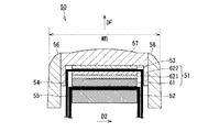
図5は、本実施形態に係るプローブ10の先端部の構造を示す断面図である。具体的には、プローブ10が有する振動素子群の第1方向D1(図1に図示)における幅を略二等分する断面の断面図である。
FIG. 5 is a cross-sectional view showing the structure of the tip of the
プローブ10は、振動素子11、バッキング材12、第3音響整合層13、充填層14、グランド(GND)リード15、信号線16、及び被覆材17を備える。
The
振動素子11は、例えば、圧電素子21、第1音響整合層221、および第2音響整合層222を備える。本実施形態におけるプローブ10は、腹部用コンベックス型の1Dプローブである。腹部用コンベックス型の1Dプローブは、胸部内臓、例えば心臓や肝臓の超音波撮影に用いられるものであり、特に全肝の走査が必要な場合に有効である。
The
本実施形態における腹部用コンベックス型の1Dプローブは、例えば中心周波数が3〜5[MHz]程度の超音波を送信可能である。腹部用コンベックス型の1Dプローブにおける第2方向(エレベーション方向)D2の有効口径WT(図6に図示)は、6〜12[mm]程度である。本実施形態におけるプローブ10は、音響的に有効な振動素子で構成される振動素子群のみを備えるため、有効口径WTは、第2方向における全ての振動素子の幅と一致する。つまり、プローブ10が1Dプローブである場合、有効口径WTは、単一の振動素子の第2方向における幅と一致する。
The abdominal convex 1D probe in the present embodiment can transmit ultrasonic waves having a center frequency of about 3 to 5 [MHz], for example. The effective aperture WT (shown in FIG. 6) in the second direction (elevation direction) D2 of the abdominal convex 1D probe is about 6 to 12 [mm]. Since the
音響整合層221,222は、圧電素子21の正面方向DFに設けられ、圧電素子21と生体との間の音響インピーダンスの差を小さくするために設けられる中間的物質である。
The acoustic matching layers 221 and 222 are intermediate materials provided in the front direction DF of the
バッキング材12は、振動素子11の背面側(正面方向DFの逆側)に設けられ、圧電素子21の共振を抑制することで短いパルス波を発生させるとともに、圧電素子21の背面側に発生する不要な超音波を吸収・減衰させる。
The
第3音響整合層13は、振動素子11の正面方向DFに設けられ、音響整合層221,222と同様に、圧電素子21と生体との間の音響インピーダンスの差を小さくするために設けられる中間的物質である。
The third
充填層14は、正面側が凸面となっており、当該凸面で被覆材17と接する。充填層14は、振動素子11で発生した超音波の第2方向D2に関する収束に寄与する。
The filling
被覆材17は、生体と接触可能な凸面を有し、単一の部材で形成され、振動素子11の正面側の全体及び側面側の少なくとも一部を被覆する。被覆材17には、従来も一部のプローブで音響レンズとして用いられてきた合成樹脂、例えば、ポリメチルペンテンが材料として用いられる。ポリメチルペンテンは、前述したように、生体(水)との音響整合性が良好である。
The covering
被覆材17は、生体に接触可能な凸面(生体接触面)(図6に図示)に対向する凹面を有することが好適である。その場合、両面の曲率半径は必ずしも一致している必要はない。そして、被覆材17の凹面と、振動素子11前面の平面との間に生じる空隙に充填層14が形成される。充填層14は、例えば音響レンズ57(図2及び図3)に比べて音速が遅く、音響インピーダンスがレンズ材と整合する材料である。
The covering
具体的には、充填層14は、シリカ等のフィラー混入により比重を調整したシリコーン接着剤であり、被覆材17と第3音響整合層13との接着に用いられる接着剤である。被覆材17の生体接触面(図6に図示)とそれに対向する内面とが同じ方向に湾曲しているので、被覆材17によるレンズ効果はほとんどなく、充填層14との音速差により超音波ビームの収束効果が得られる。
Specifically, the filling
次に、図6及び図7を用いて被覆材17の形状を説明する。
Next, the shape of the coating | covering
図6は、本実施形態に係るプローブ10の被覆材17の構造を示す断面図である。
FIG. 6 is a cross-sectional view showing the structure of the covering
図6の左側は、第2方向D2における振動素子群11sの幅を略二等分する断面の断面図である。図6の右側は、第1方向D1における振動素子群11sの幅を略二等分する断面の断面図である。
The left side of FIG. 6 is a cross-sectional view of a cross section that bisects the width of the
図6の右側に示す断面において、被覆材17の生体と接触可能な凸面は、第1の面17a(太い実線)と、第2の面17b(太い破線)とを有する。第1の面17aは凸面の中央に位置する中央面31(第1の面17aのうちラウンド面32を除く面)と、当該中央面31の両端に位置するラウンド面32とを有する。第1方向D1における振動素子群11sの幅を略二等分する断面P(図6の左側に図示)において、中央面31は第1の曲率半径を有し、ラウンド面32は第2の曲率半径を有する。第2の面17bは、振動素子群11sの少なくとも一部の側面側の面である。つまり、凸面の中央面31と第2の曲面17bとの接続面は、ラウンド処理されてなる。
In the cross section shown on the right side of FIG. 6, the convex surface of the covering
図6の右側に示す断面において、生体接触面のラウンド面32の曲率半径(R)は2[mm]程度が望ましい。ラウンド面32の曲率半径が小さすぎると、超音波撮影時にプローブ10を斜めにしたときに患者に苦痛を与えてしまう。一方で、ラウンド面32の曲率半径が大きすぎると、生体接触面の第2方向D2の幅WCが第2方向の有効口径(振動素子群11sの第2方向の幅)WTより不必要に大きくなってしまう。
In the cross section shown on the right side of FIG. 6, the radius of curvature (R) of the
そのため、本実施形態では、第1方向D1における振動素子群11sの幅を略二等分する断面における、凸面の頂点から2[mm]落ち込んだ凸面上の2点間の幅WD(図7に図示)を規定する。
Therefore, in the present embodiment, the width WD between two points on the convex surface that is 2 [mm] lower than the vertex of the convex surface in a section that bisects the width of the
図7は、被覆材17の凸面上の2点間の幅WDと、有効口径WTとの関係を説明するための図である。
FIG. 7 is a diagram for explaining the relationship between the width WD between two points on the convex surface of the covering
図7は、第1方向D1における振動素子群11sの幅を略二等分する断面における被覆材17の第1及び第2の面を、第1方向から見た図である。図7に示すように、被覆材17の凸面は、緩やかな曲面である中央面31と、曲率半径が2[mm]のラウンド面32とを含む。
FIG. 7 is a view of the first and second surfaces of the covering
中央面31は緩やかな曲面であるので、中央面31及びラウンド面32の接点から、ラウンド面32の曲率中心(曲率円の中心)への向きは、凸面の頂点から2[mm]落ち込む向きにほぼ平行とみなせる。よって、図示しないが、ラウンド面32の曲率半径のなす角が仮に直角の場合、凸面の頂点から2[mm]落ち込んだ凸面上の2点間の幅WDと第2方向D2における振動素子群11sの幅(有効口径WT)との差(WD−WT>0[mm])は4[mm]となり、片側の差がラウンド面32の曲率半径と同一の2[mm]となる。
Since the
しかし、実際には、図7に示すように、両方の第2の面17bは、互いに平行する構造ではなく背面側に向かって第2方向D2の幅が増大する構造であるので、ラウンド面32の曲率半径のなす角は鋭角となる。ラウンド面32の曲率半径のなす角が小さいほど、幅WDと、第2方向D2における振動素子群11sの幅との差は、4[mm]を超えて設定されることになる。
However, in actuality, as shown in FIG. 7, both the
患者Oの体表への接触性を考慮した、ラウンド面32の曲率半径のなす角とするために、図7に示すように、幅WDが有効口径WTより大きくなるように構成される被覆材17は、幅WDと、第2方向D2における有効口径WTとの差(WD−WT>0[mm])が5[mm]以下となるように構成される。幅WDと有効口径WTとの片側の差を、最大で2.5[mm]程度とすることが好適である。
In order to make the angle formed by the radius of curvature of the
ここで、被覆材17の先端部の正面方向DFの厚みは、薄すぎると強度が不足し、落下衝撃時に亀裂などの故障が生じ、また、ポリメチルペンテンとしての成型も困難である。一方で、被覆材17の正面方向DFの厚みが厚すぎると超音波の減衰が大きくなり、感度低下につながり、また、生体との音速の違いによる屈折の影響が大きくなってしまう。被覆材17の減衰係数は、周波数にほぼ比例するので、被覆材17の正面方向DFの厚みは、被覆材17内の波長に対する相対値で規定することが好適であり、当該波長の1.5〜3倍とする。
Here, if the thickness in the front direction DF of the front end portion of the covering
なお、被覆材17は、第2方向D2の有効口径WTが、従来のプローブ50(図2及び図3に図示)の有効口径に比較して小さいサイズ、例えば、6〜12[mm]となるように構成されてもよい。有効口径を小さくすることで、中央面31の第2方向D2の幅を小さくできるので、操作性の向上をさらに効果的にするためである。前述したように有効口径WTが減少すると、深部画質やS/N比が低下されるようにも思われる。しかしながら、深部画質やS/N比の低下は被覆材17(ポリメチルペンテン)と充填層14(シリコーンゴム)の減衰係数の差によって補償されるので、実質的には腹部の一般的な撮影に対して問題なく使用できる画質及びS/N比を維持できる。
The covering
また、より高画質を求めるために、第2方向D2にも圧電素子21を配列し、口径切り替えや独立の遅延、ゲイン制御を行なう1.5Dプローブも存在する。1.5Dプローブにおいては、6〜12[mm]という最適な最大有効口径を保って深部画質を最適化することで、最大限にプローブ10の操作性を向上することが可能である。
In order to obtain higher image quality, there is also a 1.5D probe in which the
図8は、胸部内蔵の超音波撮影が行なわれる場合のプローブ10を示す図である。
FIG. 8 is a view showing the
図8に示すように、プローブ10を用いて生体の超音波撮影を行なうためには、操作者は、体表にプローブ10を当て、肋骨Bの間(肋間)から生体を撮影すべくプローブ10を傾ける操作を行なう。生体接触面の幅WC(図6に図示)が従来の生体接触面の幅WB(図2及び図3に図示)より小さいので、肋骨裏を撮影しようとして操作者がプローブ10を大きく傾ける場合にも、プローブ10の撮影領域U2が肋間から外れて肋骨Bに係り難くなり、死角が発生し難い。また、体表との接触部分(図8に示す斜線部分)を狭めようとプローブ10を体表に深く押しつけることになっても、従来のものよりプローブ10を押し付けられる患者の負担が小さくなる。
As shown in FIG. 8, in order to perform ultrasonic imaging of a living body using the
なお、生体接触面のラウンド面31の曲率半径が2[mm]の場合において、幅WDと、第2方向D2における有効口径WTとの差(WD−WT>0[mm])が5[mm]以下というプローブ10の構造について説明したが、その場合に限定されるものではない。例えば、生体接触面のラウンド面32の曲率半径が2[mm]以外の場合であってもよい。又は、生体接触面の中央面31及びラウンド面32が一続きのスプライン曲線によって形成される面であってもよい。
When the radius of curvature of the
本実施形態に係る体外式超音波プローブ10によると、深部画質やS/N比を維持したまま、生体接触面の幅WCを小さくすることができる。その結果、操作者によるプローブ10の操作性が向上され、プローブ10を押し付けられる患者の負担が軽減される。
According to the external
また、本実施形態に係る体外式超音波プローブ10によると、振動素子11への衝撃の伝搬を抑制するものである。その結果、プローブ10の振動素子11の衝撃に起因する故障のリスクが低減される。
Further, according to the external
以上、本発明のいくつかの実施形態を説明したが、これらの実施形態は、例として提示したものであり発明の範囲を限定することは意図していない。これら新規な実施形態は、その他の様々な形態で実施されることが可能であり、発明の要旨を逸脱しない範囲で種々の省略、置き換え、変更を行なうことができる。これらの実施形態やその変形は、発明の範囲や要旨に含まれるとともに、特許請求の範囲に記載された発明とその均等の範囲に含まれる。 Although several embodiments of the present invention have been described above, these embodiments are presented as examples and are not intended to limit the scope of the invention. These novel embodiments can be implemented in various other forms, and various omissions, replacements, and changes can be made without departing from the scope of the invention. These embodiments and modifications thereof are included in the scope and gist of the invention, and are included in the invention described in the claims and the equivalents thereof.
10 超音波プローブ
11 振動素子
11s 振動素子群
12 バッキング材
14 充填層
17 被覆材
21 圧電素子
221,222 音響整合層
DESCRIPTION OF
Claims (12)
生体に接触可能な凸面を有し、単一の部材で形成され、前記振動素子群の正面側を全体的に被覆し、前記振動素子群の側面側の少なくとも一部を被覆する被覆材と、
を備え、
前記アジマス方向における前記振動素子群の幅を略二等分する断面において、前記凸面の頂点から2[mm]落ち込んだ前記凸面上の2点間の幅は、エレベーション方向における前記振動子群の幅より大きく、
前記2点間の幅と前記エレベーション方向における前記振動子群の幅の差は5[mm]以下である、体外式超音波プローブ。 A vibration element group arranged along the azimuth direction and transmitting and receiving ultrasonic waves;
A covering material that has a convex surface that can contact a living body, is formed of a single member, covers the entire front side of the vibration element group, and covers at least a part of the side surface of the vibration element group;
With
In the cross section that bisects the width of the vibration element group in the azimuth direction, the width between two points on the convex surface that is 2 [mm] lower than the vertex of the convex surface is the width of the transducer group in the elevation direction. Larger than width,
The extracorporeal ultrasonic probe, wherein a difference between the width between the two points and the width of the transducer group in the elevation direction is 5 [mm] or less.
生体に接触可能な凸面を有し、単一の部材で形成され、前記振動素子群の正面側を全体的に被覆し、前記振動素子群の側面側の少なくとも一部を被覆する被覆材と、
を備え、
前記エレベーション方向における前記振動素子群の幅は6〜12[mm]である、体外式超音波プローブ。 A vibration element group arranged along the azimuth direction and transmitting and receiving ultrasonic waves;
A covering material that has a convex surface that can contact a living body, is formed of a single member, covers the entire front side of the vibration element group, and covers at least a part of the side surface of the vibration element group;
With
The external ultrasonic probe, wherein a width of the vibrating element group in the elevation direction is 6 to 12 [mm].
前記振動素子は、前記被覆材の中心軸上の厚みが前記超音波の波長の1.5〜3倍となるように構成された請求項1乃至11のうちいずれか一項に記載の体外式超音波プローブ。 The piezoelectric element group generates an ultrasonic wave having a center frequency of the generated ultrasonic wave of 3 to 5 [MHz],
The extracorporeal type according to any one of claims 1 to 11, wherein the vibration element is configured such that a thickness on a central axis of the covering material is 1.5 to 3 times a wavelength of the ultrasonic wave. Ultrasonic probe.
Priority Applications (2)
| Application Number | Priority Date | Filing Date | Title |
|---|---|---|---|
| JP2015131601A JP6584839B2 (en) | 2015-06-30 | 2015-06-30 | Extracorporeal ultrasound probe |
| US15/169,088 US11033249B2 (en) | 2015-06-30 | 2016-05-31 | External ultrasonic probe |
Applications Claiming Priority (1)
| Application Number | Priority Date | Filing Date | Title |
|---|---|---|---|
| JP2015131601A JP6584839B2 (en) | 2015-06-30 | 2015-06-30 | Extracorporeal ultrasound probe |
Publications (3)
| Publication Number | Publication Date |
|---|---|
| JP2017012381A true JP2017012381A (en) | 2017-01-19 |
| JP2017012381A5 JP2017012381A5 (en) | 2018-06-07 |
| JP6584839B2 JP6584839B2 (en) | 2019-10-02 |
Family
ID=57683330
Family Applications (1)
| Application Number | Title | Priority Date | Filing Date |
|---|---|---|---|
| JP2015131601A Active JP6584839B2 (en) | 2015-06-30 | 2015-06-30 | Extracorporeal ultrasound probe |
Country Status (2)
| Country | Link |
|---|---|
| US (1) | US11033249B2 (en) |
| JP (1) | JP6584839B2 (en) |
Cited By (1)
| Publication number | Priority date | Publication date | Assignee | Title |
|---|---|---|---|---|
| JP2021036944A (en) * | 2019-08-30 | 2021-03-11 | キヤノンメディカルシステムズ株式会社 | Ultrasonic probe and attachment for ultrasonic probe |
Families Citing this family (1)
| Publication number | Priority date | Publication date | Assignee | Title |
|---|---|---|---|---|
| CN110392554A (en) | 2018-02-15 | 2019-10-29 | 佳能医疗系统株式会社 | The probe head of ultrasonic probe and ultrasonic probe |
Citations (7)
| Publication number | Priority date | Publication date | Assignee | Title |
|---|---|---|---|---|
| JPS59225044A (en) * | 1983-06-07 | 1984-12-18 | 松下電器産業株式会社 | Ultrasonic transducer |
| JPH0495013U (en) * | 1991-01-11 | 1992-08-18 | ||
| US5577507A (en) * | 1994-11-21 | 1996-11-26 | General Electric Company | Compound lens for ultrasound transducer probe |
| JPH0937377A (en) * | 1995-07-17 | 1997-02-07 | Nippon Dempa Kogyo Co Ltd | Array type ultrasonic probe |
| JPH11226012A (en) * | 1998-02-12 | 1999-08-24 | Hitachi Medical Corp | Ultrasonic wave probe |
| JP2009247416A (en) * | 2008-04-02 | 2009-10-29 | Nippon Dempa Kogyo Co Ltd | Acoustic lens for ultrasonic probe and ultrasonic probe using the same |
| JP2010110642A (en) * | 2010-01-18 | 2010-05-20 | Toshiba Corp | Ultrasonic diagnostic apparatus |
Family Cites Families (20)
| Publication number | Priority date | Publication date | Assignee | Title |
|---|---|---|---|---|
| US2438936A (en) * | 1943-10-06 | 1948-04-06 | Bell Telephone Labor Inc | Electromechanical transducer |
| JPS58216294A (en) * | 1982-06-10 | 1983-12-15 | 松下電器産業株式会社 | Acoustic lens |
| DE69027284T2 (en) * | 1989-12-14 | 1996-12-05 | Aloka Co Ltd | Three-dimensional ultrasound scanner |
| JP3056624U (en) | 1997-08-12 | 1999-02-26 | 孝榮 李 | Glass window wiper |
| US6419633B1 (en) * | 2000-09-15 | 2002-07-16 | Koninklijke Philips Electronics N.V. | 2D ultrasonic transducer array for two dimensional and three dimensional imaging |
| US6749406B2 (en) * | 2001-04-09 | 2004-06-15 | George Keilman | Ultrasonic pump with non-planar transducer for generating focused longitudinal waves and pumping methods |
| US7081093B2 (en) * | 2003-12-05 | 2006-07-25 | Vermon | Array transducer for 3D tilting probes |
| JP4611909B2 (en) * | 2006-02-21 | 2011-01-12 | 日本電波工業株式会社 | Short-axis ultrasonic transducer |
| US8102734B2 (en) * | 2007-02-08 | 2012-01-24 | St. Jude Medical, Atrial Fibrillation Division, Inc. | High intensity focused ultrasound transducer with acoustic lens |
| KR20080093281A (en) * | 2007-04-16 | 2008-10-21 | 주식회사 메디슨 | Ultrasound diagnostic probe |
| US20100256488A1 (en) * | 2007-09-27 | 2010-10-07 | University Of Southern California | High frequency ultrasonic convex array transducers and tissue imaging |
| JP5399660B2 (en) * | 2008-03-13 | 2014-01-29 | 富士フイルム株式会社 | Ultrasound endoscope |
| JP2010005374A (en) * | 2008-05-28 | 2010-01-14 | Nippon Dempa Kogyo Co Ltd | Minor axis motion type ultrasonic probe |
| WO2010100921A1 (en) * | 2009-03-04 | 2010-09-10 | パナソニック株式会社 | Ultrasonic transducer, ultrasonic probe, and ultrasonic diagnostic device |
| US8206307B2 (en) * | 2010-03-10 | 2012-06-26 | Dbmedx Inc. | Ultrasound imaging probe and method |
| JP5667420B2 (en) * | 2010-09-29 | 2015-02-12 | 日本電波工業株式会社 | Ultrasonic probe |
| JP5860822B2 (en) * | 2012-02-13 | 2016-02-16 | 富士フイルム株式会社 | Probe for acoustic wave detection and photoacoustic measurement apparatus having the probe |
| EP2906125A4 (en) * | 2012-10-12 | 2016-06-29 | Muffin Inc | Mechanical scanning ultrasound transducer with micromotor |
| JP6331297B2 (en) * | 2013-09-10 | 2018-05-30 | セイコーエプソン株式会社 | Ultrasonic measuring apparatus, ultrasonic imaging apparatus, and ultrasonic measuring method |
| US20170238902A1 (en) * | 2016-02-19 | 2017-08-24 | General Electric Company | System for reducing a footprint of an ultrasound transducer probe |
-
2015
- 2015-06-30 JP JP2015131601A patent/JP6584839B2/en active Active
-
2016
- 2016-05-31 US US15/169,088 patent/US11033249B2/en active Active
Patent Citations (8)
| Publication number | Priority date | Publication date | Assignee | Title |
|---|---|---|---|---|
| JPS59225044A (en) * | 1983-06-07 | 1984-12-18 | 松下電器産業株式会社 | Ultrasonic transducer |
| US4699150A (en) * | 1983-06-07 | 1987-10-13 | Matsushita Electric Industrial Co., Ltd. | Ultrasonic transducer assembly for medical diagnostic examinations |
| JPH0495013U (en) * | 1991-01-11 | 1992-08-18 | ||
| US5577507A (en) * | 1994-11-21 | 1996-11-26 | General Electric Company | Compound lens for ultrasound transducer probe |
| JPH0937377A (en) * | 1995-07-17 | 1997-02-07 | Nippon Dempa Kogyo Co Ltd | Array type ultrasonic probe |
| JPH11226012A (en) * | 1998-02-12 | 1999-08-24 | Hitachi Medical Corp | Ultrasonic wave probe |
| JP2009247416A (en) * | 2008-04-02 | 2009-10-29 | Nippon Dempa Kogyo Co Ltd | Acoustic lens for ultrasonic probe and ultrasonic probe using the same |
| JP2010110642A (en) * | 2010-01-18 | 2010-05-20 | Toshiba Corp | Ultrasonic diagnostic apparatus |
Cited By (2)
| Publication number | Priority date | Publication date | Assignee | Title |
|---|---|---|---|---|
| JP2021036944A (en) * | 2019-08-30 | 2021-03-11 | キヤノンメディカルシステムズ株式会社 | Ultrasonic probe and attachment for ultrasonic probe |
| JP7308697B2 (en) | 2019-08-30 | 2023-07-14 | キヤノンメディカルシステムズ株式会社 | Ultrasonic probes and attachments for ultrasonic probes |
Also Published As
| Publication number | Publication date |
|---|---|
| JP6584839B2 (en) | 2019-10-02 |
| US20170000459A1 (en) | 2017-01-05 |
| US11033249B2 (en) | 2021-06-15 |
Similar Documents
| Publication | Publication Date | Title |
|---|---|---|
| JP4847442B2 (en) | Ultrasonic intracavity probe for 3D imaging | |
| JP6882426B2 (en) | High frequency ultrasonic transducer with ultrasonic lens with integrated central matching layer | |
| JP6070549B2 (en) | Ultrasonic probe | |
| KR102241694B1 (en) | Ultrasound transducer and ultrasound imaging system with a variable thickness dematching layer | |
| US9808830B2 (en) | Ultrasound transducer and ultrasound imaging system with a variable thickness dematching layer | |
| KR20080093281A (en) | Ultrasound diagnostic probe | |
| EP3037180B1 (en) | Ultrasonic probe and manufacturing method thereof | |
| JP6584839B2 (en) | Extracorporeal ultrasound probe | |
| JP2014519348A5 (en) | ||
| KR101269459B1 (en) | Ultrasound probe and manufacturing method thereof | |
| KR102369731B1 (en) | Probe and manufacturing method thereof | |
| JP3990208B2 (en) | Ultrasonic probe and ultrasonic diagnostic apparatus | |
| KR101222198B1 (en) | A structure for improved receiver sensitivity of ultrasonic transducers for medical | |
| JP2020531077A5 (en) | ||
| KR20120136985A (en) | Ultrasound probe with improved skin penetration efficiency of ultrasound energy | |
| JP2012011024A (en) | Ultrasonic probe and ultrasonic diagnostic apparatus | |
| CN105147337A (en) | Ultrasonic transducer with improved sound field performance and improving method thereof | |
| JP2024014114A (en) | Ultrasonic probe and ultrasound diagnostic equipment | |
| JP4662521B2 (en) | Acoustic lens, ultrasonic probe and ultrasonic diagnostic apparatus | |
| KR102370812B1 (en) | Ultrasound transducer | |
| JP2024512698A (en) | Imaging device with piezoelectric transceiver with harmonic properties | |
| Ekeom et al. | Design of a phased-array for radiation force generation following a closed path | |
| JPS63305848A (en) | Ultrasonic probe | |
| Han et al. | The basic principles and techniques of ultrasound. | |
| JP2010219634A (en) | Ultrasonic probe and ultrasonic diagnostic device |
Legal Events
| Date | Code | Title | Description |
|---|---|---|---|
| A711 | Notification of change in applicant |
Free format text: JAPANESE INTERMEDIATE CODE: A711 Effective date: 20160506 |
|
| A521 | Request for written amendment filed |
Free format text: JAPANESE INTERMEDIATE CODE: A523 Effective date: 20180330 |
|
| A621 | Written request for application examination |
Free format text: JAPANESE INTERMEDIATE CODE: A621 Effective date: 20180330 |
|
| A977 | Report on retrieval |
Free format text: JAPANESE INTERMEDIATE CODE: A971007 Effective date: 20190124 |
|
| A131 | Notification of reasons for refusal |
Free format text: JAPANESE INTERMEDIATE CODE: A131 Effective date: 20190212 |
|
| A521 | Request for written amendment filed |
Free format text: JAPANESE INTERMEDIATE CODE: A523 Effective date: 20190415 |
|
| TRDD | Decision of grant or rejection written | ||
| A01 | Written decision to grant a patent or to grant a registration (utility model) |
Free format text: JAPANESE INTERMEDIATE CODE: A01 Effective date: 20190806 |
|
| A61 | First payment of annual fees (during grant procedure) |
Free format text: JAPANESE INTERMEDIATE CODE: A61 Effective date: 20190904 |
|
| R150 | Certificate of patent or registration of utility model |
Ref document number: 6584839 Country of ref document: JP Free format text: JAPANESE INTERMEDIATE CODE: R150 |