JP2017012304A - Stick type vacuum cleaner - Google Patents

Stick type vacuum cleaner Download PDF

Info

Publication number
JP2017012304A
JP2017012304A JP2015130258A JP2015130258A JP2017012304A JP 2017012304 A JP2017012304 A JP 2017012304A JP 2015130258 A JP2015130258 A JP 2015130258A JP 2015130258 A JP2015130258 A JP 2015130258A JP 2017012304 A JP2017012304 A JP 2017012304A
Authority
JP
Japan
Prior art keywords
vacuum cleaner
pipe
extension
extension pipe
suction port
Prior art date
Legal status (The legal status is an assumption and is not a legal conclusion. Google has not performed a legal analysis and makes no representation as to the accuracy of the status listed.)
Granted
Application number
JP2015130258A
Other languages
Japanese (ja)
Other versions
JP6863673B2 (en
Inventor
直子 品川
Naoko Shinagawa
直子 品川
市野 雄之
Takeyuki Ichino
雄之 市野
幸雄 町田
Yukio Machida
幸雄 町田
井上 勉
Tsutomu Inoue
勉 井上
孝吉 清水
Kokichi Shimizu
孝吉 清水
Current Assignee (The listed assignees may be inaccurate. Google has not performed a legal analysis and makes no representation or warranty as to the accuracy of the list.)
Toshiba Lifestyle Products and Services Corp
Original Assignee
Toshiba Lifestyle Products and Services Corp
Priority date (The priority date is an assumption and is not a legal conclusion. Google has not performed a legal analysis and makes no representation as to the accuracy of the date listed.)
Filing date
Publication date
Application filed by Toshiba Lifestyle Products and Services Corp filed Critical Toshiba Lifestyle Products and Services Corp
Priority to JP2015130258A priority Critical patent/JP6863673B2/en
Publication of JP2017012304A publication Critical patent/JP2017012304A/en
Application granted granted Critical
Publication of JP6863673B2 publication Critical patent/JP6863673B2/en
Active legal-status Critical Current
Anticipated expiration legal-status Critical

Links

Images

Abstract

PROBLEM TO BE SOLVED: To provide a stick type vacuum cleaner with a high degree of freedom in a storage place and high convenience in storage and taking-out (the use start of the cleaner).SOLUTION: A stick type vacuum cleaner 1 includes: a cleaner body 3 having a grip 2 and to be operated in a hand-held manner; an electric blower 8 stored in the cleaner body 3 and generating suction negative pressure; an extensible extention pipe 5 to be fluid-connected with the suction side of the electric blower 8; a suction port body 6 to be fluid-connected with the suction side of the electric blower 8 via the extention pipe 5 and having a suction port 21; and a storage base 31 for enabling the reduction of the extention pipe 5 by mounting the integrally connected cleaner body 3, extention pipe 5, and suction port body 6, and storing the suction port body 6, the reduced extention pipe 5, and the cleaner body 3 in a standing posture.SELECTED DRAWING: Figure 3

Description

本発明に係る実施形態はスティック型電気掃除機に関する。   Embodiments according to the present invention relate to a stick-type vacuum cleaner.

従来のスティック型電気掃除機は、使用しない時に直立のドック位置に支持する、壁掛式のドッキングステーションを含んでいる。   Conventional stick vacuum cleaners include a wall-mounted docking station that supports an upright dock position when not in use.

特開2011−189132号公報JP 2011-189132 A

スティック型電気掃除機は、手元側の掃除機本体に重量を集中させ、吸込口体側の重量を軽くして取り回し性を高めている。   The stick type vacuum cleaner concentrates the weight on the vacuum cleaner body on the hand side, and reduces the weight on the suction port body side to improve the handling performance.

ところが、スティック型電気掃除機は、手元側の掃除機本体に重量を集中させているために重心が高く、起立させたまま保管、収納することが難しい。   However, the stick-type vacuum cleaner has a high center of gravity because it concentrates the weight on the vacuum cleaner body on the hand side, and it is difficult to store and store it while standing upright.

そこで、従来のスティック型電気掃除機は、壁掛式のドッキングステーションに掃除機本体を引っ掛け、延長管を下方へ垂れ下げる姿勢でぶら下がるように収納されている。   Therefore, the conventional stick-type vacuum cleaner is housed so that the cleaner body is hung on a wall-mounted docking station, and the extension tube is hung downward.

しかしながら、壁掛式のドッキングステーションは、壁にねじ穴を必要とするため、所望の収納場所にドッキングステーションを配置することが困難になる。   However, since the wall-hanging docking station requires a screw hole in the wall, it is difficult to arrange the docking station at a desired storage location.

また、従来のスティック型電気掃除機は、ドッキングステーションへ着脱する際にドッキングステーションの頂部に配置されるピボットを中心に揺動するため、揺動範囲を確保するためにもドッキングステーションの配置は制約される。   In addition, the conventional stick-type vacuum cleaner swings around a pivot placed at the top of the docking station when being attached to or detached from the docking station, so the placement of the docking station is also limited to ensure a swing range. Is done.

そこで、本発明は、収納場所の自由度が高く、収納および取り出し(掃除機の使用開始)の利便性を高めたスティック型電気掃除機を提供することを目的とする。   Therefore, an object of the present invention is to provide a stick-type vacuum cleaner that has a high degree of freedom in a storage location and has improved convenience of storage and removal (start of use of the vacuum cleaner).

前記の課題を解決するため本発明の実施形態に係るスティック型電気掃除機は、把手を有する手持ち操作可能な掃除機本体と、前記掃除機本体に収容されて吸込負圧を生じさせる電動送風機と、前記電動送風機の吸込側に流体的に接続される伸縮可能な延長管と、を備え、前記延長管は、前記掃除機本体に機械的に連結される内管と、前記内管を内部に収納することによって前記掃除機本体へ近づく一方、前記内管を内部から引き出すことによって前記掃除機本体から遠ざかって前記延長管の全長を伸縮させる外管と、前記外管側に設けられて前記内管に対する前記外管の固定および固定の解除を行う固定部と、を備えている。   In order to solve the above-mentioned problems, a stick type vacuum cleaner according to an embodiment of the present invention includes a vacuum cleaner main body having a handle and an electric blower that is accommodated in the vacuum cleaner main body and generates suction negative pressure. A telescopic extension pipe fluidly connected to the suction side of the electric blower, the extension pipe mechanically connected to the cleaner body, and the inner pipe inside An outer tube that extends closer to the vacuum cleaner main body while retracting from the inside of the vacuum cleaner main body while retracting from the cleaner main body by extending and retracting the entire length of the extension pipe, and is provided on the outer pipe side. A fixing portion that fixes and releases the outer tube with respect to the tube.

本発明の第1実施形態に係るスティック型電気掃除機を示す斜視図。The perspective view which shows the stick type vacuum cleaner which concerns on 1st Embodiment of this invention. 本発明の第1実施形態に係るスティック型電気掃除機を示す側面図。The side view which shows the stick type vacuum cleaner which concerns on 1st Embodiment of this invention. 本発明の第1実施形態に係るスティック型電気掃除機を示す側面図。The side view which shows the stick type vacuum cleaner which concerns on 1st Embodiment of this invention. 本発明の第2実施形態に係るスティック型電気掃除機を示す斜視図。The perspective view which shows the stick type vacuum cleaner which concerns on 2nd Embodiment of this invention. 本発明の第2実施形態に係るスティック型電気掃除機を示す側面図。The side view which shows the stick type vacuum cleaner which concerns on 2nd Embodiment of this invention. 本発明の第2実施形態に係るスティック型電気掃除機を示す側面図。The side view which shows the stick type vacuum cleaner which concerns on 2nd Embodiment of this invention. 本発明の第2実施形態に係るスティック型電気掃除機の固定解除部の追従機能を示す断面図。Sectional drawing which shows the tracking function of the fixing release part of the stick type vacuum cleaner which concerns on 2nd Embodiment of this invention.

以下、本発明に係るスティック型電気掃除機の実施の形態について、図面を参照して説明する。   Hereinafter, embodiments of a stick type vacuum cleaner according to the present invention will be described with reference to the drawings.

[第1の実施形態]
本発明に係るスティック型電気掃除機の第1実施形態について図1から図3を参照して説明する。
[First Embodiment]
A stick type vacuum cleaner according to a first embodiment of the present invention will be described with reference to FIGS.

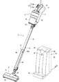
図1は、本発明の第1実施形態に係るスティック型電気掃除機を示す斜視図である。   FIG. 1 is a perspective view showing a stick type vacuum cleaner according to a first embodiment of the present invention.

図2は、本発明の第1実施形態に係るスティック型電気掃除機を示す側面図である。   FIG. 2 is a side view showing the stick type vacuum cleaner according to the first embodiment of the present invention.

図1および図2に示すように、本実施形態に係るスティック型電気掃除機1は、把手2を有する手持ち操作可能な掃除機本体3と、掃除機本体3に接続される伸縮可能な延長管5と、延長管5に接続される吸込口体6と、を備えている。   As shown in FIGS. 1 and 2, a stick-type vacuum cleaner 1 according to the present embodiment includes a vacuum cleaner main body 3 having a handle 2 that can be operated by hand, and an extendable extension tube connected to the vacuum cleaner main body 3. 5 and a suction port body 6 connected to the extension pipe 5.

掃除機本体3は、把手2を有する本体ケース7と、本体ケース7に収容されて吸込負圧を生じさせる電動送風機8と、本体ケース7に着脱自在に設けられる塵埃分離集塵部9と、主に電動送風機8を制御する本体制御部10と、電動送風機8や本体制御部10へ供給される電力を蓄える二次電池11と、を備えている。   The vacuum cleaner main body 3 includes a main body case 7 having a handle 2, an electric blower 8 that is accommodated in the main body case 7 and generates suction negative pressure, a dust separating and collecting unit 9 that is detachably provided in the main body case 7, A main body control unit 10 that mainly controls the electric blower 8 and a secondary battery 11 that stores electric power supplied to the electric blower 8 and the main body control unit 10 are provided.

掃除機本体3は、二次電池11に蓄えた電力によって電動送風機8を駆動させて、電動送風機8の駆動によって発生する負圧を延長管5に作用させている。スティック型電気掃除機1は、吸込口体6および延長管5を通じて床面から塵埃を含んだ空気(以下、「含塵空気」と呼ぶ。)を吸い込み、含塵空気から塵埃を分離し、分離後の塵埃を捕集し、蓄積するとともに分離後の空気を排気する。   The cleaner body 3 drives the electric blower 8 with the electric power stored in the secondary battery 11, and causes the negative pressure generated by the drive of the electric blower 8 to act on the extension pipe 5. The stick type vacuum cleaner 1 sucks air containing dust from the floor (hereinafter referred to as “dusty air”) through the suction port 6 and the extension pipe 5 and separates dust from the dusty air. Dust is collected and accumulated, and the separated air is exhausted.

本体ケース7は、側面視において延長管5の延長線上に配置される円筒状の前半部と、前半部から屈曲して延長管5の延長線から徐々に離れる後半部と、を備えている。本体ケース7の前半部の上面には、塵埃分離集塵部9が併設されている。本体ケース7の後半部は、吸込口体6を床上に配置した使用状態(図2)において、後方へ向かって延びている。   The body case 7 includes a cylindrical front half portion that is disposed on the extension line of the extension tube 5 in a side view, and a rear half portion that is bent from the front half portion and gradually moves away from the extension line of the extension tube 5. On the upper surface of the front half of the main body case 7, a dust separating and collecting part 9 is provided. The rear half of the main body case 7 extends rearward in a use state (FIG. 2) in which the suction port body 6 is disposed on the floor.

本体ケース7の正面部分には、本体接続口12が設けられている。本体接続口12は、延長管5を着脱可能な継手である。本体接続口12は、掃除機本体3の流体的な入口であり、延長管5と塵埃分離集塵部9とを流体的に接続している。   A main body connection port 12 is provided in the front portion of the main body case 7. The main body connection port 12 is a joint to which the extension pipe 5 can be attached and detached. The main body connection port 12 is a fluid inlet of the cleaner body 3, and fluidly connects the extension pipe 5 and the dust separating and collecting part 9.

把手2は本体ケース7に一体に設けられている。把手2は、スティック型電気掃除機1で床面を掃除するために使用者が手で把持する部分である。把手2は、塵埃分離集塵部9の後端部の近傍から本体ケース7の後端部へアーチ状に架かっている。また、把手2は、延長管5の延長線L上に掛かって配置されている。   The handle 2 is provided integrally with the main body case 7. The handle 2 is a part that the user grips with the hand in order to clean the floor surface with the stick-type vacuum cleaner 1. The handle 2 is arched from the vicinity of the rear end portion of the dust separating and collecting portion 9 to the rear end portion of the main body case 7. Further, the handle 2 is disposed on the extension line L of the extension pipe 5.

把手2の近傍には、把手2を握った使用者が、その手指を動かせる範囲に配置される入力部13が設けられている。   In the vicinity of the handle 2, an input unit 13 is provided that is arranged in a range in which a user who holds the handle 2 can move his / her fingers.

入力部13は、電動送風機8の運転開始操作を受け付ける運転開始スイッチ13aと、電動送風機8の運転停止操作を受け付ける運転停止スイッチ13bと、を備えている。運転開始スイッチ13aおよび運転停止スイッチ13bは、本体制御部10に電気的に接続されている。スティック型電気掃除機1の使用者は、入力部13を操作して電動送風機8の運転モードを択一的に選択できる。運転開始スイッチ13aは、電動送風機8の運転中に、運転モードの切替スイッチとしても機能している。この場合、本体制御部10は、運転開始スイッチ13aから操作信号を受け取る度に運転モードを強→中→弱→強→中→弱→………の順に切り換える。なお、入力部13は、運転開始スイッチ13aに代えて、強運転スイッチ(図示省略)、中運転スイッチ(図示省略)、および弱運転スイッチ(図示省略)を個別に備えていても良い。   The input unit 13 includes an operation start switch 13 a that receives an operation start operation of the electric blower 8 and an operation stop switch 13 b that receives an operation stop operation of the electric blower 8. The operation start switch 13 a and the operation stop switch 13 b are electrically connected to the main body control unit 10. The user of the stick type vacuum cleaner 1 can alternatively select the operation mode of the electric blower 8 by operating the input unit 13. The operation start switch 13 a also functions as an operation mode changeover switch during operation of the electric blower 8. In this case, every time an operation signal is received from the operation start switch 13a, the main body control unit 10 switches the operation mode in the order of strong → medium → weak → strong → medium → weak →. The input unit 13 may include a strong operation switch (not shown), a medium operation switch (not shown), and a weak operation switch (not shown) instead of the operation start switch 13a.

塵埃分離集塵部9は、掃除機本体3に流れ込む含塵空気から塵埃を分離し、捕集し、蓄積する一方で、塵埃が除去された清浄な空気を電動送風機8へ送る。塵埃分離集塵部9は、遠心分離方式であっても良いし、濾過分離方式であっても良い。   The dust separating and collecting unit 9 separates dust from the dust-containing air flowing into the cleaner body 3, collects and accumulates it, and sends clean air from which dust has been removed to the electric blower 8. The dust separation and collection unit 9 may be a centrifugal separation method or a filtration separation method.

電動送風機8は、塵埃分離集塵部9から空気を吸い込んで負圧(吸込負圧)を発生させる。   The electric blower 8 sucks air from the dust separation and collection unit 9 to generate negative pressure (suction negative pressure).

本体制御部10は、マイクロプロセッサ(図示省略)、およびマイクロプロセッサが実行する各種演算プログラム、パラメータなどを記憶する記憶装置(図示省略)を備えている。記憶装置には、予め設定される複数の運転モードが記憶されている。予め設定される複数の運転モードは、電動送風機8の運転出力の大小に関連するものであって、入力部13で受け付けられる使用者の操作に対応している。それぞれの運転モードには、相互に異なる入力値(電動送風機8の入力値)が予め設定されている。本体制御部10は、入力部13で受け付けられる使用者の操作に応じて、その操作内容に対応する任意の運転モードを予め設定される複数の運転モードから択一的に選択して記憶部から読み出し、読み出した運転モードにしたがって電動送風機8を制御する。   The main body control unit 10 includes a microprocessor (not shown) and a storage device (not shown) that stores various calculation programs, parameters, and the like executed by the microprocessor. The storage device stores a plurality of preset operation modes. The plurality of operation modes set in advance are related to the magnitude of the operation output of the electric blower 8 and correspond to the user's operation accepted by the input unit 13. In each operation mode, different input values (input values of the electric blower 8) are set in advance. The main body control unit 10 selectively selects an arbitrary operation mode corresponding to the operation content from a plurality of preset operation modes in accordance with a user operation received by the input unit 13 from the storage unit. The electric blower 8 is controlled according to the read operation mode.

二次電池11は、本体ケース7内に設けられていても良いし、本体ケース7外に着脱自在、ひいては交換自在に装着されるものであっても良い。   The secondary battery 11 may be provided in the main body case 7, or may be detachably attached to the main body case 7, and may be attached in a replaceable manner.

延長管5および吸込口体6は、電動送風機8から作用する負圧によって、床面上の塵埃を空気とともに吸い込んで掃除機本体3へ案内する。   The extension pipe 5 and the suction port body 6 suck the dust on the floor together with the air by the negative pressure acting from the electric blower 8 and guide it to the cleaner body 3.

延長管5は、本体ケース7の本体接続口12および塵埃分離集塵部9を介して電動送風機8の吸込側に流体的に接続されている。延長管5は、使用者が掃除機本体3の把手2を把持した状態で実質的に床面に届く長さを有する。   The extension pipe 5 is fluidly connected to the suction side of the electric blower 8 via the main body connection port 12 of the main body case 7 and the dust separating and collecting part 9. The extension pipe 5 has a length that substantially reaches the floor surface while the user holds the handle 2 of the cleaner body 3.

また、延長管5は、複数の筒状体を重ね合わせたテレスコピック構造を有する。つまり延長管5は、伸縮可能な細長略円筒状の管である。延長管5の一方の端部には、掃除機本体3の本体接続口12に着脱自在な継手構造が設けられている。延長管5の他方の端部には、掃除機本体3の吸込口体6を着脱自在な継手構造が設けられている。   The extension pipe 5 has a telescopic structure in which a plurality of cylindrical bodies are overlapped. That is, the extension pipe 5 is an elongated substantially cylindrical pipe that can be expanded and contracted. At one end of the extension pipe 5, a joint structure that can be attached to and detached from the main body connection port 12 of the cleaner body 3 is provided. The other end of the extension pipe 5 is provided with a joint structure that allows the suction port body 6 of the cleaner body 3 to be detachable.

延長管5は、内管15と、内管15が内部に収納され、または内管15が内部から引き出されることによって延長管5の全長を伸縮させる外管16と、外管16側に設けられて内管15に対する外管16の固定および固定の解除を行う固定部17と、を備えている。   The extension pipe 5 is provided on the inner pipe 15, the outer pipe 16 in which the inner pipe 15 is accommodated in the inner pipe 15, or the inner pipe 15 is pulled out of the inner pipe 15 to extend and contract the entire length of the extension pipe 5. And a fixing portion 17 for fixing and releasing the fixing of the outer tube 16 with respect to the inner tube 15.

内管15は、掃除機本体3に機械的に連結される。外管16は、内管15を内部に収納することによって掃除機本体3へ近づく一方、内管15を内部から引き出すことによって掃除機本体3から遠ざかって延長管5の全長を伸縮させる。つまり、延長管5は、掃除機本体3側から見て近い側に内管15を備え、掃除機本体3側から見て遠い側に外管16を備えている。   The inner tube 15 is mechanically connected to the cleaner body 3. The outer tube 16 approaches the cleaner body 3 by housing the inner tube 15 therein, while extending and retracting the entire length of the extension tube 5 away from the cleaner body 3 by pulling out the inner tube 15 from the inside. That is, the extension pipe 5 includes the inner pipe 15 on the side closer to the vacuum cleaner main body 3 and the outer pipe 16 on the side farther from the vacuum cleaner main body 3 side.

固定部17は、外管16の掃除機本体3に近い側の端部16aに設けられている。また、固定部17は、外管16の掃除機本体3に近い側の端部16aを把持する使用者の手指が届く範囲において、外管16の上面側、下面側(図1、図2)、側面側のいずれの箇所に配置されていても良い。   The fixing portion 17 is provided at an end portion 16 a of the outer tube 16 on the side close to the cleaner body 3. In addition, the fixing portion 17 has an upper surface side and a lower surface side (FIGS. 1 and 2) of the outer tube 16 within the reach of the finger of the user who holds the end 16a of the outer tube 16 on the side close to the cleaner body 3. It may be arranged at any location on the side surface side.

固定部17は、外管16の外周面から露出する押しボタン18と、押しボタン18に一体のフック(図示省略)と、押しボタン18を押し返す方向へばね力を発生させるコイルばね(図示省略)と、を備えている。押しボタン18とフックとの間には支点があり、押しボタン18が外管16の中心線方向へ押し込まれると、フックが外管16の中心線から離れる方向へ移動する。   The fixing portion 17 includes a push button 18 exposed from the outer peripheral surface of the outer tube 16, a hook (not shown) integrated with the push button 18, and a coil spring (not shown) that generates a spring force in a direction in which the push button 18 is pushed back. And. There is a fulcrum between the push button 18 and the hook, and when the push button 18 is pushed in the direction of the center line of the outer tube 16, the hook moves in a direction away from the center line of the outer tube 16.

フックは、内管15側に設けられる凹部(図示省略)に引っ掛かって延長管5の長さを固定する。押しボタン18が外管16の中心線方向へ押し込まれて、フックが外管16の中心線から離れる方向へ移動すると、内管15と外管16との固定が解除されて伸縮自在になる。なお、内管15側に設けられる凹部は、延長管5を最長の長さ(図2)で固定および固定の解除をするもののほか、延長管5を最短の長さで固定および固定の解除をするもの、延長管5を最長の長さから最短の長さまでの間で段階的に固定および固定の解除を可能な少なくとも1つの凹部などを含んで複数、設けられていても良い。   The hook is hooked in a recess (not shown) provided on the inner tube 15 side to fix the length of the extension tube 5. When the push button 18 is pushed in the direction of the center line of the outer tube 16 and the hook moves in a direction away from the center line of the outer tube 16, the inner tube 15 and the outer tube 16 are released from being fixed and can be expanded and contracted. The recess provided on the inner tube 15 side fixes and releases the extension tube 5 with the longest length (FIG. 2), and also fixes and releases the extension tube 5 with the shortest length. A plurality of extension pipes 5 may be provided including at least one recess that can be fixed and released in a stepwise manner from the longest length to the shortest length.

コイルばねは、押しボタン18を押し返す方向、つまり内管15の凹部にフックが引っ掛かる方向へばね力を作用させている。   The coil spring applies a spring force in the direction in which the push button 18 is pushed back, that is, in the direction in which the hook is caught in the recess of the inner tube 15.

吸込口体6は、木床やカーペットなどの床面上を走行自在または滑走自在であり、走行状態または滑走状態において床面に対向する底面に吸込口21を有する。また、吸込口体6は、吸込口21に配置される回転自在な回転清掃体22と、回転清掃体22を駆動させる電動機23と、を備えている。吸込口体6の一方の端部には、延長管5の他方の端部に着脱自在な継手構造が設けられている。吸込口体6は、延長管5を介して電動送風機8の吸込側に流体的に接続されている。吸込口体6、延長管5、および塵埃分離集塵部9は、電動送風機8から吸込口21へ至る吸込風路である。   The suction port body 6 can run or slide on a floor surface such as a wooden floor or a carpet, and has a suction port 21 on the bottom surface facing the floor surface in the running state or the sliding state. The suction port body 6 includes a rotatable rotary cleaning body 22 disposed in the suction port 21 and an electric motor 23 that drives the rotary cleaning body 22. A joint structure that is detachable from the other end of the extension pipe 5 is provided at one end of the suction port body 6. The suction port body 6 is fluidly connected to the suction side of the electric blower 8 through the extension pipe 5. The suction port body 6, the extension pipe 5, and the dust separation / collection part 9 are suction air paths from the electric blower 8 to the suction port 21.

なお、吸込口体6は、電動機23に代えて回転清掃体22を駆動させる風車(図示省略)を備えていても良い。この風車は、スティック型電気掃除機1に吸い込まれる空気の流動によって回転し、回転清掃体22を駆動させる。   The suction port body 6 may include a windmill (not shown) that drives the rotary cleaning body 22 instead of the electric motor 23. The windmill rotates by the flow of air sucked into the stick type vacuum cleaner 1 and drives the rotary cleaning body 22.

スティック型電気掃除機1は、運転開始スイッチ13aで使用者の操作を検知すると電動送風機8を始動させる。例えば、スティック型電気掃除機1は、電動送風機8が停止している状態で運転開始スイッチ13aに対する操作を受け付けると、先ず電動送風機8を強運転モードで運転し、再び運転開始スイッチ13aに対する操作を受け付けると電動送風機8を中運転モードで運転し、三度、運転開始スイッチ13aに対する操作を受け付けると電動送風機8を弱運転モードで運転し、以下同様に繰り返す。強運転モード、中運転モードおよび弱運転モードは、予め設定される複数の運転モードであり、強運転モード、中運転モード、弱運転モードの順に電動送風機8に対する入力値が小さい。始動した電動送風機8は、塵埃分離集塵部9から空気を排気してその内部を負圧にする。   The stick type vacuum cleaner 1 starts the electric blower 8 when the operation of the user is detected by the operation start switch 13a. For example, when the stick-type vacuum cleaner 1 receives an operation on the operation start switch 13a while the electric blower 8 is stopped, the electric blower 8 is first operated in the strong operation mode, and the operation on the operation start switch 13a is performed again. If accepted, the electric blower 8 is operated in the medium operation mode, and if the operation on the operation start switch 13a is accepted three times, the electric blower 8 is operated in the weak operation mode, and the same is repeated thereafter. The strong operation mode, the medium operation mode, and the weak operation mode are a plurality of operation modes set in advance, and the input value to the electric blower 8 is small in the order of the strong operation mode, the medium operation mode, and the weak operation mode. The started electric blower 8 exhausts air from the dust separation and collection unit 9 to make the inside negative pressure.

塵埃分離集塵部9内の負圧は、本体接続口12、延長管5、および吸込口体6を順次に通じて吸込口21に作用する。スティック型電気掃除機1は、吸込口21に作用した負圧によって、被掃除面上の塵埃を空気とともに吸い込んで被掃除面を掃除する。塵埃分離集塵部9は、スティック型電気掃除機1に吸い込まれた含塵空気から塵埃を分離し、蓄積する一方で、含塵空気から分離した空気を電動送風機8へ送る。電動送風機8は、塵埃分離集塵部9から吸い込んだ空気を掃除機本体3外へ排気する。   The negative pressure in the dust separating and collecting part 9 acts on the suction port 21 through the main body connection port 12, the extension pipe 5, and the suction port body 6 in order. The stick type vacuum cleaner 1 cleans the surface to be cleaned by sucking dust on the surface to be cleaned together with air by the negative pressure acting on the suction port 21. The dust separating and collecting unit 9 separates and accumulates dust from the dust-containing air sucked into the stick type vacuum cleaner 1, and sends the air separated from the dust-containing air to the electric blower 8. The electric blower 8 exhausts the air sucked from the dust separating and collecting part 9 to the outside of the cleaner body 3.

また、スティック型電気掃除機1は、一体に接続された掃除機本体3、延長管5、吸込口体6を起立姿勢で収納する収納台31を備えている。   The stick-type vacuum cleaner 1 includes a storage base 31 that stores the vacuum cleaner body 3, the extension pipe 5, and the suction port body 6 that are connected together in an upright position.

収納台31は、床面上に置かれる。収納台31は、一体に接続された掃除機本体3、延長管5および吸込口体6が装着されることで延長管5を縮小可能にし、吸込口体6、縮小された延長管5および掃除機本体3を起立姿勢で収納する。   The storage table 31 is placed on the floor surface. The storage base 31 is provided with the vacuum cleaner main body 3, the extension pipe 5 and the suction port body 6 which are integrally connected, so that the extension pipe 5 can be reduced, and the suction port body 6, the reduced extension pipe 5 and the cleaning pipe 31 are cleaned. The machine body 3 is stored in a standing posture.

収納台31は、一体に接続された吸込口体6、延長管5および掃除機本体3が装着されると、固定部17を機能させて内管15と外管16との固定を解除し、延長管5を縮小可能にする固定解除部32を備えている。   When the suction port body 6, the extension pipe 5 and the cleaner body 3 which are integrally connected are mounted, the storage base 31 functions the fixing portion 17 to release the fixing between the inner pipe 15 and the outer pipe 16, A fixing release portion 32 that enables the extension tube 5 to be reduced is provided.

図3は、本発明の第1実施形態に係るスティック型電気掃除機を示す側面図である。   FIG. 3 is a side view showing the stick type vacuum cleaner according to the first embodiment of the present invention.

図3に示すように、本実施形態に係るスティック型電気掃除機1は、一体に接続された吸込口体6、延長管5および掃除機本体3を、収納台31に組み合わせることによって、起立姿勢のまま、床面への投影面積A(あるいは設置面積A)を極力小さくして収納することができる。なお、図3には、延長管5が最も伸張された状態を二点鎖線で示し、延長管5が最も縮小された状態を実線で示している。このとき、掃除機本体3は延長管5の上側の端部に接続されており、把手2は起立姿勢においてスティック型電気掃除機1の頂部付近に配置されることになる。   As shown in FIG. 3, the stick-type vacuum cleaner 1 according to the present embodiment has a standing posture by combining the suction port body 6, the extension pipe 5 and the vacuum cleaner body 3 that are integrally connected to the storage base 31. Thus, the projected area A (or installation area A) on the floor surface can be kept as small as possible. In FIG. 3, a state in which the extension tube 5 is most expanded is indicated by a two-dot chain line, and a state in which the extension tube 5 is most contracted is indicated by a solid line. At this time, the cleaner body 3 is connected to the upper end of the extension pipe 5, and the handle 2 is arranged near the top of the stick-type vacuum cleaner 1 in the standing posture.

収納台31は、吸込口体6を定位置で定置させるストッパ33を備えている。ストッパ33は、収納台31に組み合わせられた吸込口体6、延長管5および掃除機本体3が、収納台31からずれ落ちないように吸込口体6の移動を阻止している。また、ストッパ33は、固定解除部32に延長管5の押しボタン18が押し付けられた際の反力を支持する役割を兼ねている。   The storage base 31 includes a stopper 33 for placing the suction port body 6 at a fixed position. The stopper 33 prevents movement of the suction port body 6 so that the suction port body 6, the extension pipe 5, and the cleaner body 3 combined with the storage table 31 do not fall off the storage table 31. The stopper 33 also serves to support a reaction force when the push button 18 of the extension pipe 5 is pressed against the fixing release portion 32.

また、収納台31は、収納台31に設けられて掃除機本体3が収納台31に収納されると二次電池11へ電力を供給する充電路35を備えている。充電路35は、掃除機本体3が収納台31に収納されると二次電池11へ電気的に接続される端子36を備えている。掃除機本体3も、掃除機本体3が収納台31に収納されると端子36に接して充電路35と二次電池11とを電気的に接続する端子(図示省略)が設けられている。   Further, the storage table 31 includes a charging path 35 that is provided on the storage table 31 and supplies power to the secondary battery 11 when the cleaner body 3 is stored in the storage table 31. The charging path 35 includes a terminal 36 that is electrically connected to the secondary battery 11 when the cleaner body 3 is stored in the storage base 31. The vacuum cleaner body 3 is also provided with a terminal (not shown) that contacts the terminal 36 and electrically connects the charging path 35 and the secondary battery 11 when the vacuum cleaner body 3 is stored in the storage base 31.

延長管5の固定部17は、吸込口体6、延長管5および掃除機本体3を、収納台31に装着すると収納台31の固定解除部32によって内管15と外管16との固定を解除する。具体的には、収納台31の固定解除部32は、吸込口体6、延長管5および掃除機本体3を、収納台31に組み合わせると固定部17の押しボタン18を押し込む位置に設けられた突起である。固定解除部32は、吸込口体6、延長管5および掃除機本体3が収納台31に装着されている限り固定部17の押しボタン18を押し込み続ける。つまり、延長管5は、吸込口体6、延長管5および掃除機本体3が収納台31に装着されている限り、内管15と外管16との固定が解除された状態が保たれる。したがって、延長管5は、掃除機本体3を持ち上げたり、下ろしたりすることによって容易に伸縮する。また、延長管5は、固定解除部32によって縮小可能になると掃除機本体3の重量で縮小することになる。   The fixing part 17 of the extension pipe 5 fixes the inner pipe 15 and the outer pipe 16 by the fixing release part 32 of the storage base 31 when the suction port body 6, the extension pipe 5 and the cleaner body 3 are attached to the storage base 31. To release. Specifically, the fixing release portion 32 of the storage base 31 is provided at a position where the push button 18 of the fixing portion 17 is pressed when the suction port body 6, the extension pipe 5 and the cleaner body 3 are combined with the storage base 31. It is a protrusion. The fixing release part 32 continues to push the push button 18 of the fixing part 17 as long as the suction port body 6, the extension pipe 5 and the cleaner body 3 are mounted on the storage base 31. That is, the extension pipe 5 is kept in a state where the inner pipe 15 and the outer pipe 16 are released from being fixed as long as the suction port body 6, the extension pipe 5, and the cleaner body 3 are mounted on the storage base 31. . Accordingly, the extension pipe 5 easily expands and contracts by lifting or lowering the cleaner body 3. Further, when the extension tube 5 can be reduced by the fixing release portion 32, the extension tube 5 is reduced by the weight of the cleaner body 3.

また、延長管5は、収納台31から取り外される動作に一連して伸張する。具体的には、吸込口体6、延長管5および掃除機本体3を、収納台31から取り外して使用するときには、先ず、使用者は、収納台31上の掃除機本体3の把手2を把持して延長管5の伸縮方向へ引き上げ、延長管5が延びきったところで吸込口体6、延長管5および掃除機本体3を一体で、収納台31から取り外すことによって、伸張した延長管5で掃除を始めることができる。   Further, the extension pipe 5 extends in a series of operations to be removed from the storage base 31. Specifically, when the suction port body 6, the extension pipe 5, and the cleaner body 3 are removed from the storage table 31, the user first holds the handle 2 of the cleaner body 3 on the storage table 31. Then, the extension pipe 5 is pulled up in the expansion / contraction direction, and when the extension pipe 5 has been fully extended, the suction port body 6, the extension pipe 5 and the cleaner body 3 are integrally removed from the storage base 31, thereby extending the extension pipe 5. You can start cleaning.

ところで、延長管5の内管15は、延長管5がもっとも縮んだ状態においても外管16の外側に残る所定長さDの残存部25を有している。   By the way, the inner tube 15 of the extension tube 5 has a remaining portion 25 having a predetermined length D that remains outside the outer tube 16 even when the extension tube 5 is most contracted.

スティック型電気掃除機1の使用者は、一方の手で掃除機本体3の把手2を把持し、他方の手で外管16の一方の端部、つまり掃除機本体3に近い側の端部16aを把持して、固定部17で外管16と内管15との固定を解除し、両手を近づけることで延長管5を縮小させることができる。   The user of the stick type vacuum cleaner 1 holds the handle 2 of the vacuum cleaner main body 3 with one hand and the other end of the outer tube 16 with the other hand, that is, the end near the vacuum cleaner main body 3. The extension tube 5 can be reduced by grasping 16a, releasing the fixation between the outer tube 16 and the inner tube 15 by the fixing portion 17, and bringing both hands closer to each other.

また、スティック型電気掃除機1の使用者は、一方の手で掃除機本体3の把手2を把持し、他方の手で外管16の一方の端部、つまり掃除機本体3に近い側の端部16aを把持して、固定部17で外管16と内管15との固定を解除し、両手を遠ざけることで延長管5を伸張させることができる。   The user of the stick type vacuum cleaner 1 holds the handle 2 of the vacuum cleaner main body 3 with one hand and the other end of the outer tube 16 with the other hand, that is, the side closer to the vacuum cleaner main body 3. The extension tube 5 can be extended by grasping the end portion 16a, releasing the fixation between the outer tube 16 and the inner tube 15 by the fixing portion 17, and keeping both hands away.

これら、延長管5の伸縮操作、特に縮小動作において、掃除機本体3に外管16が実質的に接する状態まで延長管5を縮小させることができる場合、つまり延長管5を最も短縮させた状態において内管15が露出することなく隠蔽されてしまう場合、外管16の端部16aを把持する手指の一部、例えば小指から薬指を外管16と掃除機本体3との間、または外管16と内管15の継手部との間に挟み込んでしまい、使用者が思わぬ負傷をしてしまう恐れがある。   When the extension tube 5 can be reduced to a state in which the outer tube 16 is substantially in contact with the cleaner body 3 in the expansion / contraction operation of the extension tube 5, particularly in the reduction operation, that is, the extension tube 5 is most shortened. If the inner tube 15 is concealed without being exposed, a part of the finger that holds the end 16a of the outer tube 16, for example, a ring finger from the little finger is placed between the outer tube 16 and the cleaner body 3, or the outer tube. 16 and the joint portion of the inner tube 15 may cause an unexpected injury to the user.

そこで、本実施形態に係るスティック型電気掃除機1の内管15は、延長管5が最も縮んだ状態においても外管16の外側に残る所定長さDの残存部25を有している。   Therefore, the inner tube 15 of the stick-type vacuum cleaner 1 according to the present embodiment has a remaining portion 25 having a predetermined length D that remains outside the outer tube 16 even when the extension tube 5 is contracted most.

残存部25は、外管16と掃除機本体3との間、または外管16と内管15の継手部との間に手指の一部を挟まない程度、例えば3センチメートル以上あれば良い。   The remaining portion 25 may be at least 3 centimeters, for example, so as not to sandwich a part of a finger between the outer tube 16 and the cleaner body 3 or between the outer tube 16 and the joint portion of the inner tube 15.

ところで、従来のキャニスタ型電気掃除機は、把手のある手元側に配置される外管と、把手から見て外管よりも遠くに配置される内管と、を備えている。使用者は、一方の手で把手に近い外管を把持しつつ固定部で外管と内管との固定を解除し、他方の手で把手から遠い内管の適宜の箇所を把持して延長管を伸縮させている。   By the way, the conventional canister type vacuum cleaner is provided with the outer tube | pipe arrange | positioned at the hand side with a handle, and the inner tube | pipe arrange | positioned far from an outer tube | pipe seeing from a handle. The user holds the outer tube close to the handle with one hand, releases the fixation between the outer tube and the inner tube with the fixing part, and holds and extends an appropriate portion of the inner tube far from the handle with the other hand. The tube is stretched.

他方、本実施形態に係るスティック型電気掃除機1は、延長管5や吸込口体6に比べて重量の重い掃除機本体3に把手2を有している。このスティック型電気掃除機1では、従来のキャニスタ型電気掃除機を使い慣れた使用者が、習慣的に一方の手で把手2に近い内管15を把持し、他方の手で把手2から遠い外管16を把持しつつ固定部17で外管16と内管15との固定を解除して、延長管5を伸縮させようとする恐れがある。   On the other hand, the stick type vacuum cleaner 1 according to the present embodiment has a handle 2 in the vacuum cleaner body 3 that is heavier than the extension pipe 5 and the suction port body 6. In this stick type vacuum cleaner 1, a user who is accustomed to using a conventional canister type vacuum cleaner customarily holds the inner tube 15 close to the handle 2 with one hand, and is distant from the handle 2 with the other hand. There is a possibility that the fixing portion 17 may release the fixation between the outer tube 16 and the inner tube 15 while gripping the tube 16 and try to expand and contract the extension tube 5.

そして、スティック型電気掃除機1は、内管15側に重量の大きい掃除機本体3を有しているため、習慣的に一方の手で把手2に近い内管15を把持し、他方の手で把手2から遠い外管16を把持しつつ固定部17で外管16と内管15との固定を解除して、延長管5を伸縮させようとする場合、内管15を把持する手の握力が掃除機本体3の重量を支えきれずに、掃除機本体3の自重で落下するような状態で延長管5が急激に縮小してしまう恐れがある。掃除機本体3の自重で落下するような状態で延長管5が急激に縮小してしまうとき、使用者は、外管16と掃除機本体3との間、または外管16と内管15の継手部との間に手指を挟まれて負傷してしまう恐れがある。   And since the stick type vacuum cleaner 1 has the heavy vacuum cleaner main body 3 on the inner tube 15 side, the inner tube 15 close to the handle 2 is routinely gripped with one hand, and the other hand When the outer tube 16 far from the handle 2 is gripped and the fixing portion 17 releases the fixation between the outer tube 16 and the inner tube 15 and the extension tube 5 is to be expanded and contracted, the hand holding the inner tube 15 There is a possibility that the extension pipe 5 may be rapidly reduced in such a state that the gripping force cannot support the weight of the cleaner body 3 and falls due to its own weight. When the extension pipe 5 is suddenly reduced in a state where the vacuum cleaner body 3 falls due to its own weight, the user can place the space between the outer pipe 16 and the cleaner body 3 or between the outer pipe 16 and the inner pipe 15. There is a risk of fingers being pinched between the joint and injury.

そこで、本実施形態に係るスティック型電気掃除機1の内管15は、延長管5がもっとも縮んだ状態においても外管16の外側に残る所定長さDの残存部25を有している。   Therefore, the inner tube 15 of the stick-type vacuum cleaner 1 according to the present embodiment has a remaining portion 25 having a predetermined length D that remains outside the outer tube 16 even when the extension tube 5 is contracted most.

残存部25は、外管16と掃除機本体3との間に手指の全体を挟まない程度、例えば11センチメートル以上あれば良い。   The remaining portion 25 only needs to be at least 11 centimeters, for example, so that the entire finger is not sandwiched between the outer tube 16 and the cleaner body 3.

つまり、一方の手で掃除機本体3の把手2を把持し、他方の手で外管16の掃除機本体3に近い側の端部16aを把持して延長管5を伸縮させる場合には、残存部25は、外管16と掃除機本体3との間に手指の一部を挟まない程度、例えば3センチメートル以上あれば良く、他方、一方の手で内管15を把持し、他方の手で外管16を把持して延長管5を伸縮させる場合には、残存部25は、外管16と掃除機本体3との間に手指の全体を挟まない程度、例えば11センチメートル以上あれば良いので、残存部25を11センチメートル以上、確保しておくことで延長管5の安全性を高められる。なお、残存部25は、内管15の継手部を含まず、外管16の内側へ出没する部分と同じ外径を有している。   That is, when gripping the handle 2 of the cleaner body 3 with one hand and gripping the end 16a of the outer tube 16 near the cleaner body 3 with the other hand, The remaining portion 25 only needs to be 3 centimeters or more, for example, so that a part of a finger is not sandwiched between the outer tube 16 and the cleaner body 3, and on the other hand, the inner tube 15 is gripped by one hand, When the outer tube 16 is gripped by hand and the extension tube 5 is expanded and contracted, the remaining portion 25 should not be sandwiched between the outer tube 16 and the cleaner body 3, for example, 11 cm or more. Therefore, the safety of the extension pipe 5 can be improved by securing the remaining portion 25 of 11 centimeters or more. The remaining portion 25 does not include the joint portion of the inner tube 15 and has the same outer diameter as that of the portion that protrudes into and out of the outer tube 16.

また、残存部25は、一体に接続された吸込口体6、延長管5および掃除機本体3を収納台31に組合せ、起立姿勢で収納する際にも、使用者や、使用者以外に収納台31の近傍にいる他者が、縮小する延長管5に挟まれて負傷することを回避し、安産性を高めている。   In addition, the remaining portion 25 can be accommodated by the user or other than the user when the suction port body 6, the extension pipe 5 and the cleaner body 3 which are integrally connected are combined with the storage base 31 and stored in a standing posture. Others in the vicinity of the base 31 are prevented from being injured by being sandwiched between the contracting extension pipes 5, thereby improving the productivity.

このように構成される本実施形態に係るスティック型電気掃除機1は、伸縮可能な延長管5と、一体に接続された掃除機本体3、延長管5および吸込口体6が装着されることで延長管5を縮小可能にし、吸込口体6、縮小された延長管5および掃除機本体3を起立姿勢で収納する収納台31と、を備えることによって、従来のスティック型電気掃除機における壁掛式のドッキングステーションにようにねじ穴による壁の損傷がなく、設置面積Aを確保可能な所望の収納場所に収納することができる。   The stick type vacuum cleaner 1 according to the present embodiment configured as described above is provided with the extendable extension pipe 5, the vacuum cleaner main body 3, the extension pipe 5 and the suction port body 6 which are integrally connected. The extension pipe 5 can be reduced in size, and includes a suction port body 6, a reduced extension pipe 5 and a storage base 31 for storing the vacuum cleaner main body 3 in an upright position. As in the case of the docking station of the type, there is no damage to the wall due to the screw hole, and it can be stored in a desired storage place where the installation area A can be secured.

また、本実施形態に係るスティック型電気掃除機1は、伸縮可能な延長管5と、一体に接続された掃除機本体3、延長管5および吸込口体6が装着されることで延長管5を縮小可能にし、吸込口体6、縮小された延長管5および掃除機本体3を起立姿勢で収納する収納台31と、を備えることによって、起立姿勢における頂部付近に把手2が配置されることになり、使用開始の利便性も高い。   Further, the stick type vacuum cleaner 1 according to the present embodiment is provided with the extension tube 5 that can be expanded and contracted, and the extension tube 5 by attaching the vacuum cleaner body 3, the extension tube 5, and the suction port body 6 that are integrally connected. The handle 2 is disposed near the top in the standing posture by providing the suction port body 6, the reduced extension pipe 5 and the storage base 31 for storing the cleaner body 3 in the standing posture. Therefore, the convenience of starting use is also high.

さらに、本実施形態に係るスティック型電気掃除機1は、収納台31に一体に接続された掃除機本体3、延長管5および吸込口体6が装着されることで延長管5の固定部17が解除され、延長管5を掃除機本体3の自重で縮小できるので、特別な操作を必要とせず、一体に接続された掃除機本体3、延長管5および吸込口体6を収納台31に装着する一連の動作によって収納状態に移行できる。   Furthermore, the stick type vacuum cleaner 1 according to the present embodiment is equipped with the vacuum cleaner main body 3, the extension pipe 5, and the suction port body 6 that are integrally connected to the storage base 31, so that the fixing portion 17 of the extension pipe 5 is attached. Is released and the extension pipe 5 can be reduced by the weight of the vacuum cleaner body 3, so that no special operation is required, and the vacuum cleaner body 3, the extension pipe 5, and the suction port body 6 that are integrally connected to the storage base 31. It is possible to shift to the storage state by a series of operations for mounting.

さらにまた、本実施形態に係るスティック型電気掃除機1は、収納台31に一体に接続された掃除機本体3、延長管5および吸込口体6が収納されている状態で延長管5の固定部17が解除されているため、一体に接続された掃除機本体3、延長管5および吸込口体6を収納台31から取り外す一連の動作によって延長管5を伸ばした状態で円滑に掃除を始められる。   Furthermore, the stick type vacuum cleaner 1 according to the present embodiment fixes the extension pipe 5 in a state in which the cleaner body 3, the extension pipe 5 and the suction port body 6 integrally connected to the storage base 31 are stored. Since the part 17 is released, the cleaning body 3, the extension pipe 5 and the suction port body 6 which are connected together are removed from the storage base 31 and then the cleaning starts smoothly with the extension pipe 5 extended. It is done.

また、本実施形態に係るスティック型電気掃除機1は、充電台を兼ねる収納台31を備えることによって、一体に接続された掃除機本体3、延長管5および吸込口体6をコードレスな状態で使用でき、しかも収納時に二次電池11の充電を済ませることができる。   Moreover, the stick type vacuum cleaner 1 according to the present embodiment includes the storage base 31 that also serves as a charging stand, so that the integrally connected vacuum cleaner body 3, the extension pipe 5, and the suction port body 6 are in a cordless state. In addition, the secondary battery 11 can be charged when stored.

さらに、本実施形態に係るスティック型電気掃除機1は、伸縮可能な延長管5を備えるため、狭い場所や手元から近い場所であっても取り回し性を高めて様々な利用シーンに対応できる。   Furthermore, since the stick type vacuum cleaner 1 according to this embodiment includes the extendable tube 5 that can be expanded and contracted, it can handle various usage scenes with improved handling performance even in a narrow place or a place close to the hand.

さらにまた、本実施形態に係るスティック型電気掃除機1は、掃除機本体3の把手2の近くに配置される内管15と、内管15よりも遠くに配置される外管16とを備えることによって、一方の手で掃除機本体3の把手2を把持し、他方の手で外管16を把持して両腕を近づける操作によって延長管5を容易に伸縮させることができる。   Furthermore, the stick type vacuum cleaner 1 according to this embodiment includes an inner tube 15 disposed near the handle 2 of the cleaner body 3 and an outer tube 16 disposed farther than the inner tube 15. Accordingly, the extension tube 5 can be easily expanded and contracted by an operation of holding the handle 2 of the cleaner body 3 with one hand and holding the outer tube 16 with the other hand to bring both arms closer.

また、本実施形態に係るスティック型電気掃除機1は、外管16の掃除機本体3に近い側の端部16aに設けられる固定部17を備えているため、一方の手で掃除機本体3の把手2を把持し、他方の手で外管16を把持しつつ、内管15と外管16との固定を解除しやすく、外管16を把持する一連の動作で延長管5を円滑に伸縮できる。   Moreover, since the stick type vacuum cleaner 1 which concerns on this embodiment is provided with the fixing | fixed part 17 provided in the edge part 16a of the outer tube 16 near the cleaner main body 3, the cleaner main body 3 with one hand. The outer tube 16 is gripped by the other hand, the inner tube 15 and the outer tube 16 are easily released from being fixed, and the extension tube 5 is smoothly moved by a series of operations for gripping the outer tube 16. Can expand and contract.

さらに、本実施形態に係るスティック型電気掃除機1は、延長管5の延長線上に掛かって配置される把手2を備えているので、把手2を持つ手をそのままに、両腕の間隔を狭める動作によって延長管5を伸縮させることができるので、掃除機本体3に集中する重量に影響されることなく、延長管5の伸縮時にスティック型電気掃除機1の落下を回避しやすい。   Furthermore, since the stick type vacuum cleaner 1 according to the present embodiment includes the handle 2 arranged on the extension line of the extension pipe 5, the distance between both arms is narrowed while keeping the hand holding the handle 2 as it is. Since the extension tube 5 can be expanded and contracted by the operation, the stick-type vacuum cleaner 1 can be easily prevented from dropping when the extension tube 5 is expanded and contracted without being affected by the weight concentrated on the cleaner body 3.

さらにまた、本実施形態に係るスティック型電気掃除機1は、延長管5が最も縮んだ状態においても外管16の外側に残る所定長さの残存部25を有する内管15を備えているため、延長管の伸縮操作において安全性を高められる。   Furthermore, since the stick type vacuum cleaner 1 according to the present embodiment includes the inner tube 15 having the remaining portion 25 having a predetermined length remaining outside the outer tube 16 even when the extension tube 5 is contracted most. The safety of the extension tube can be increased and decreased.

[第2の実施形態]
本発明に係るスティック型電気掃除機の第2実施形態について図4から図7を参照して説明する。
[Second Embodiment]
A second embodiment of the stick type vacuum cleaner according to the present invention will be described with reference to FIGS.

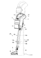
図4は、本発明の第2実施形態に係るスティック型電気掃除機を示す斜視図である。   FIG. 4 is a perspective view showing a stick type vacuum cleaner according to a second embodiment of the present invention.

図5は、本発明の第2実施形態に係るスティック型電気掃除機を示す側面図である。   FIG. 5 is a side view showing a stick type vacuum cleaner according to a second embodiment of the present invention.

なお、本実施形態において、第1実施形態と共通する構成には同一の符号を付し、重複する説明は省略する。   Note that in this embodiment, the same reference numerals are given to the same components as those in the first embodiment, and duplicate descriptions are omitted.

図4および図5に示すように、本実施形態に係るスティック型電気掃除機1Aは、把手2を有する手持ち操作可能な掃除機本体3と、掃除機本体3に接続される伸縮可能な延長管5Aと、延長管5Aに接続される吸込口体6と、を備えている。   As shown in FIGS. 4 and 5, a stick-type vacuum cleaner 1 </ b> A according to the present embodiment includes a vacuum cleaner main body 3 having a handle 2, and a telescopic extension tube connected to the vacuum cleaner main body 3. 5A and a suction port body 6 connected to the extension pipe 5A.

掃除機本体3は、二次電池11に蓄えた電力によって電動送風機8を駆動させて、電動送風機8の駆動によって発生する負圧を延長管5Aに作用させている。スティック型電気掃除機1は、吸込口体6および延長管5Aを通じて床面から塵埃を含んだ空気(以下、「含塵空気」と呼ぶ。)を吸い込み、含塵空気から塵埃を分離し、分離後の塵埃を捕集し、蓄積するとともに分離後の空気を排気する。   The vacuum cleaner body 3 drives the electric blower 8 with the electric power stored in the secondary battery 11, and causes the negative pressure generated by the drive of the electric blower 8 to act on the extension pipe 5 </ b> A. The stick type vacuum cleaner 1 sucks air containing dust (hereinafter referred to as “dusty air”) from the floor through the suction port 6 and the extension pipe 5A, and separates dust from the dusty air. Dust is collected and accumulated, and the separated air is exhausted.

本体ケース7は、側面視において延長管5Aの延長線上に配置される円筒状の前半部と、前半部から屈曲して延長管5Aの延長線から徐々に離れる後半部と、を備えている。   The body case 7 includes a cylindrical front half portion that is disposed on the extension line of the extension tube 5A in a side view, and a rear half portion that is bent from the front half portion and gradually leaves the extension line of the extension tube 5A.

本体ケース7の正面部分には、本体接続口12が設けられている。本体接続口12は、延長管5Aを着脱可能な継手である。本体接続口12は、掃除機本体3の流体的な入口であり、延長管5Aと塵埃分離集塵部9とを流体的に接続している。   A main body connection port 12 is provided in the front portion of the main body case 7. The main body connection port 12 is a joint to which the extension pipe 5A can be attached and detached. The main body connection port 12 is a fluid inlet of the cleaner body 3 and fluidly connects the extension pipe 5 </ b> A and the dust separating and collecting part 9.

把手2は、延長管5Aの延長線L上に掛かって配置されている。   The handle 2 is placed on the extension line L of the extension pipe 5A.

延長管5Aおよび吸込口体6は、電動送風機8から作用する負圧によって、床面上の塵埃を空気とともに吸い込んで掃除機本体3へ案内する。   The extension pipe 5 </ b> A and the suction port body 6 suck the dust on the floor together with the air by the negative pressure acting from the electric blower 8 and guide it to the cleaner body 3.

延長管5Aは、本体ケース7の本体接続口12および塵埃分離集塵部9を介して電動送風機8の吸込側に流体的に接続されている。延長管5Aは、使用者が掃除機本体3の把手2を把持した状態で実質的に床面に届く長さを有する。   The extension pipe 5 </ b> A is fluidly connected to the suction side of the electric blower 8 through the main body connection port 12 of the main body case 7 and the dust separating and collecting part 9. The extension pipe 5 </ b> A has a length that substantially reaches the floor surface in a state where the user holds the handle 2 of the cleaner body 3.

また、延長管5Aは、複数の筒状体を重ね合わせたテレスコピック構造を有する。つまり延長管5Aは、伸縮可能な細長略円筒状の管である。延長管5Aの一方の端部には、掃除機本体3の本体接続口12に着脱自在な継手構造が設けられている。延長管5Aの他方の端部には、掃除機本体3の吸込口体6を着脱自在な継手構造が設けられている。   The extension pipe 5A has a telescopic structure in which a plurality of cylindrical bodies are overlapped. That is, the extension tube 5A is an elongated substantially cylindrical tube that can be expanded and contracted. A joint structure detachably attached to the main body connection port 12 of the cleaner body 3 is provided at one end of the extension pipe 5A. At the other end of the extension pipe 5A, a joint structure is provided in which the suction port body 6 of the cleaner body 3 is detachable.

延長管5Aは、内管15Aと、内管15Aが内部に収納され、または内管15Aが内部から引き出されることによって延長管5Aの全長を伸縮させる外管16Aと、外管16A側に設けられて内管15Aに対する外管16Aの固定および固定の解除を行う固定部17Aと、を備えている。   The extension pipe 5A is provided on the side of the outer pipe 16A, the inner pipe 15A, the outer pipe 16A in which the inner pipe 15A is housed, or the inner pipe 15A is pulled out from the inside to expand and contract the entire length of the extension pipe 5A. And a fixing portion 17A for fixing and releasing the fixing of the outer tube 16A to the inner tube 15A.

外管16Aは、掃除機本体3に機械的に連結されている。   The outer tube 16 </ b> A is mechanically connected to the cleaner body 3.

内管15Aは、外管16Aの内部に収納されることによって掃除機本体3へ近づく一方、外管16Aの内部から引き出されることによって掃除機本体3から遠ざかって延長管5の全長を伸縮させる。つまり、延長管5Aは、掃除機本体3側から見て近い側に外管16Aを備え、掃除機本体3側から見て遠い側に内管15Aを備えている。   The inner tube 15A approaches the cleaner body 3 by being housed in the outer tube 16A, while being extended away from the cleaner body 3 by being pulled out from the outer tube 16A to extend and contract the entire length of the extension tube 5. That is, the extension tube 5A includes an outer tube 16A on the side closer to the cleaner body 3 side, and an inner tube 15A on the side farther from the cleaner body 3 side.

固定部17Aは、外管16Aの掃除機本体3から遠い側の端部16bに設けられている。また、固定部17Aは、外管16Aの掃除機本体3から遠い側の端部16bを把持する使用者の手指が届く範囲において、外管16Aの上面側(図4、図5)、下面側、側面側のいずれの箇所に配置されていても良い。   The fixing portion 17A is provided at an end portion 16b of the outer tube 16A on the side far from the cleaner body 3. In addition, the fixing portion 17A has an upper surface side (FIGS. 4 and 5), a lower surface side of the outer tube 16A within a range where a user's finger that holds the end portion 16b of the outer tube 16A far from the cleaner body 3 can reach. It may be arranged at any location on the side surface side.

固定部17Aは、外管16Aの外周面から露出する押しボタン18Aと、押しボタン18Aに一体のフック(図示省略)と、押しボタン18Aを押し返す方向へばね力を発生させるコイルばね(図示省略)と、を備えている。押しボタン18Aとフックとの間には支点があり、押しボタン18Aが外管16Aの中心線方向へ押し込まれると、フックが外管16Aの中心線から離れる方向へ移動する。   The fixing portion 17A includes a push button 18A exposed from the outer peripheral surface of the outer tube 16A, a hook (not shown) integrated with the push button 18A, and a coil spring (not shown) that generates a spring force in a direction to push back the push button 18A. And. There is a fulcrum between the push button 18A and the hook, and when the push button 18A is pushed in the direction of the center line of the outer tube 16A, the hook moves away from the center line of the outer tube 16A.

フックは、内管15A側に設けられる凹部(図示省略)に引っ掛かって延長管5Aの長さを固定する。押しボタン18Aが外管16Aの中心線方向へ押し込まれて、フックが外管16Aの中心線から離れる方向へ移動すると、内管15Aと外管16Aとの固定が解除されて伸縮自在になる。なお、内管15A側に設けられる凹部は、延長管5Aを最長の長さ(図5)で固定および固定の解除をするもののほか、延長管5Aを最短の長さで固定および固定の解除をするもの、延長管5Aを最長の長さから最短の長さまでの間で段階的に固定および固定の解除を可能な少なくとも1つの凹部などを含んで複数、設けられていても良い。   The hook is hooked in a recess (not shown) provided on the inner tube 15A side to fix the length of the extension tube 5A. When the push button 18A is pushed in the direction of the center line of the outer tube 16A and the hook moves in a direction away from the center line of the outer tube 16A, the inner tube 15A and the outer tube 16A are unfixed and can be expanded and contracted. The recess provided on the inner tube 15A side fixes and releases the extension tube 5A with the longest length (FIG. 5), and also fixes and releases the extension tube 5A with the shortest length. Alternatively, a plurality of extension pipes 5A may be provided including at least one recess that can be fixed and released in a stepwise manner from the longest length to the shortest length.

コイルばねは、押しボタン18Aを押し返す方向、つまり内管15Aの凹部にフックが引っ掛かる方向へばね力を作用させている。   The coil spring applies a spring force in a direction in which the push button 18A is pushed back, that is, in a direction in which the hook is caught in the concave portion of the inner tube 15A.

吸込口体6の一方の端部には、延長管5Aの他方の端部に着脱自在な継手構造が設けられている。吸込口体6は、延長管5Aを介して電動送風機8の吸込側に流体的に接続されている。吸込口体6、延長管5A、および塵埃分離集塵部9は、電動送風機8から吸込口21へ至る吸込風路である。   A joint structure that is detachable from the other end of the extension pipe 5 </ b> A is provided at one end of the suction port body 6. The suction port body 6 is fluidly connected to the suction side of the electric blower 8 through the extension pipe 5A. The suction port body 6, the extension pipe 5 </ b> A, and the dust separation and collection unit 9 are suction air paths from the electric blower 8 to the suction port 21.

スティック型電気掃除機1Aは、運転開始スイッチ13aで使用者の操作を検知すると電動送風機8を始動させる。例えば、スティック型電気掃除機1Aは、電動送風機8が停止している状態で運転開始スイッチ13aに対する操作を受け付けると、先ず電動送風機8を強運転モードで運転し、再び運転開始スイッチ13aに対する操作を受け付けると電動送風機8を中運転モードで運転し、三度、運転開始スイッチ13aに対する操作を受け付けると電動送風機8を弱運転モードで運転し、以下同様に繰り返す。強運転モード、中運転モードおよび弱運転モードは、予め設定される複数の運転モードであり、強運転モード、中運転モード、弱運転モードの順に電動送風機8に対する入力値が小さい。始動した電動送風機8は、塵埃分離集塵部9から空気を排気してその内部を負圧にする。   The stick type vacuum cleaner 1 </ b> A starts the electric blower 8 when the operation start switch 13 a detects a user operation. For example, when the stick-type vacuum cleaner 1A receives an operation on the operation start switch 13a while the electric blower 8 is stopped, the electric blower 8 is first operated in the strong operation mode, and the operation on the operation start switch 13a is performed again. If accepted, the electric blower 8 is operated in the medium operation mode, and if the operation on the operation start switch 13a is accepted three times, the electric blower 8 is operated in the weak operation mode, and the same is repeated thereafter. The strong operation mode, the medium operation mode, and the weak operation mode are a plurality of operation modes set in advance, and the input value to the electric blower 8 is small in the order of the strong operation mode, the medium operation mode, and the weak operation mode. The started electric blower 8 exhausts air from the dust separation and collection unit 9 to make the inside negative pressure.

塵埃分離集塵部9内の負圧は、本体接続口12、延長管5A、および吸込口体6を順次に通じて吸込口21に作用する。スティック型電気掃除機1Aは、吸込口21に作用した負圧によって、被掃除面上の塵埃を空気とともに吸い込んで被掃除面を掃除する。塵埃分離集塵部9は、スティック型電気掃除機1Aに吸い込まれた含塵空気から塵埃を分離し、蓄積する一方で、含塵空気から分離した空気を電動送風機8へ送る。電動送風機8は、塵埃分離集塵部9から吸い込んだ空気を掃除機本体3外へ排気する。   The negative pressure in the dust separating and collecting part 9 acts on the suction port 21 through the main body connection port 12, the extension pipe 5A, and the suction port body 6 in order. The stick type vacuum cleaner 1 </ b> A cleans the surface to be cleaned by sucking dust on the surface to be cleaned together with air by the negative pressure acting on the suction port 21. The dust separating and collecting unit 9 separates and accumulates dust from the dust-containing air sucked into the stick type vacuum cleaner 1 </ b> A, and sends the air separated from the dust-containing air to the electric blower 8. The electric blower 8 exhausts the air sucked from the dust separating and collecting part 9 to the outside of the cleaner body 3.

また、スティック型電気掃除機1Aは、一体に接続された掃除機本体3、延長管5、吸込口体6を起立姿勢で収納する収納台31Aを備えている。   The stick type vacuum cleaner 1 </ b> A includes a storage base 31 </ b> A that stores the vacuum cleaner body 3, the extension pipe 5, and the suction port body 6 that are integrally connected in a standing posture.

収納台31Aは、床面上に置かれる。収納台31Aは、一体に接続された掃除機本体3、延長管5Aおよび吸込口体6が装着されることで延長管5Aを縮小可能にし、吸込口体6、縮小された延長管5Aおよび掃除機本体3を起立姿勢で収納する。   The storage base 31A is placed on the floor surface. The storage base 31A allows the extension pipe 5A to be reduced by mounting the vacuum cleaner body 3, the extension pipe 5A, and the suction port body 6 which are integrally connected, and the suction port body 6, the reduced extension pipe 5A and the cleaning pipe 31A. The machine body 3 is stored in a standing posture.

収納台31Aは、一体に接続された吸込口体6、延長管5Aおよび掃除機本体3が装着されると、固定部17Aを機能させて内管15Aと外管16Aとの固定を解除し、延長管5Aを縮小可能にする固定解除部32Aを備えている。   When the suction port body 6, the extension pipe 5A, and the cleaner body 3 that are integrally connected are mounted, the storage base 31A causes the fixing portion 17A to function to release the fixation between the inner pipe 15A and the outer pipe 16A, A fixing release portion 32A that enables reduction of the extension tube 5A is provided.

図6は、本発明の第2実施形態に係るスティック型電気掃除機を示す側面図である。   FIG. 6 is a side view showing a stick type vacuum cleaner according to a second embodiment of the present invention.

図6に示すように、本実施形態に係るスティック型電気掃除機1Aは、一体に接続された吸込口体6、延長管5Aおよび掃除機本体3を、収納台31Aに組み合わせることによって、起立姿勢のまま、床面への投影面積A(あるいは設置面積A)を極力小さくして収納することができる。なお、図6には、延長管5Aが最も伸張された状態を二点鎖線で示し、延長管5Aが最も縮小された状態を実線で示している。このとき、掃除機本体3は延長管5Aの上側の端部に接続されており、把手2は起立姿勢においてスティック型電気掃除機1Aの頂部付近に配置されることになる。   As shown in FIG. 6, the stick-type vacuum cleaner 1A according to the present embodiment is in a standing posture by combining the suction port body 6, the extension pipe 5A, and the vacuum cleaner body 3 that are integrally connected to the storage base 31A. Thus, the projected area A (or installation area A) on the floor surface can be kept as small as possible. In FIG. 6, a state in which the extension tube 5A is most expanded is indicated by a two-dot chain line, and a state in which the extension tube 5A is most contracted is indicated by a solid line. At this time, the cleaner body 3 is connected to the upper end of the extension pipe 5A, and the handle 2 is arranged near the top of the stick-type vacuum cleaner 1A in the standing posture.

収納台31Aは、吸込口体6を定位置で定置させるストッパ33Aを備えている。ストッパ33Aは、収納台31Aに組み合わせられた吸込口体6、延長管5Aおよび掃除機本体3が、収納台31Aからずれ落ちないように吸込口体6の移動を阻止している。また、ストッパ33Aは、固定解除部32Aに延長管5Aの押しボタン18Aが押し付けられた際の反力を支持する役割を兼ねている。   The storage base 31A includes a stopper 33A that places the suction port body 6 at a fixed position. The stopper 33 </ b> A prevents the suction port body 6 from moving so that the suction port body 6, the extension pipe 5 </ b> A, and the cleaner body 3 combined with the storage table 31 </ b> A do not fall off the storage table 31 </ b> A. The stopper 33A also serves to support a reaction force when the push button 18A of the extension pipe 5A is pressed against the fixing release portion 32A.

また、収納台31Aは、収納台31Aに設けられて掃除機本体3が収納台31Aに収納されると二次電池11へ電力を供給する充電路35を備えている。   The storage table 31A includes a charging path 35 that is provided on the storage table 31A and supplies power to the secondary battery 11 when the cleaner body 3 is stored in the storage table 31A.

延長管5Aの固定部17Aは、吸込口体6、延長管5Aおよび掃除機本体3を、収納台31に装着すると収納台31Aの固定解除部32Aによって内管15と外管16との固定を解除する。具体的には、収納台31Aの固定解除部32Aは、吸込口体6、延長管5Aおよび掃除機本体3を、収納台31Aに組み合わせると固定部17Aの押しボタン18Aを押し込む位置に設けられた突起である。   The fixing portion 17A of the extension pipe 5A fixes the inner pipe 15 and the outer pipe 16 by the fixing release part 32A of the storage base 31A when the suction port body 6, the extension pipe 5A and the cleaner body 3 are mounted on the storage base 31. To release. Specifically, the fixing release portion 32A of the storage base 31A is provided at a position where the push button 18A of the fixing portion 17A is pressed when the suction port body 6, the extension pipe 5A, and the cleaner body 3 are combined with the storage base 31A. It is a protrusion.

ところで、スティック型電気掃除機1の延長管5は、延長管5が伸縮しても吸込口体6から固定部17までの距離が変わらないため、収納台31の固定解除部32が収納台31に固定されていても固定部17が解除されている状態を保つことができる。他方、スティック型電気掃除機1Aの延長管5Aは、延長管5Aが伸縮すると吸込口体6から固定部17Aまでの距離が変わってしまう。そこで、収納台31Aの固定解除部32Aは、延長管5Aの伸縮に応じ、つまり固定部17Aの移動に追従する。   By the way, the extension pipe 5 of the stick type vacuum cleaner 1 does not change the distance from the suction port body 6 to the fixing part 17 even if the extension pipe 5 expands and contracts. Even if it is fixed to, the state where the fixing portion 17 is released can be maintained. On the other hand, the extension pipe 5A of the stick type vacuum cleaner 1A changes the distance from the suction port body 6 to the fixed portion 17A when the extension pipe 5A expands and contracts. Therefore, the fixing release portion 32A of the storage base 31A follows the expansion and contraction of the extension pipe 5A, that is, follows the movement of the fixing portion 17A.

固定解除部32Aは、この追従機能によって、吸込口体6、延長管5Aおよび掃除機本体3が収納台31Aに装着されている限り固定部17Aの押しボタン18Aを押し込み続ける。つまり、延長管5Aは、吸込口体6、延長管5Aおよび掃除機本体3が収納台31Aに装着されている限り、内管15Aと外管16Aとの固定が解除された状態が保たれる。したがって、延長管5Aは、掃除機本体3を持ち上げたり、下ろしたりすることによって容易に伸縮する。また、延長管5Aは、固定解除部32Aによって縮小可能になると掃除機本体3の重量で縮小することになる。   With this follow-up function, the fixing release portion 32A continues to push the push button 18A of the fixing portion 17A as long as the suction port body 6, the extension pipe 5A, and the cleaner body 3 are mounted on the storage base 31A. That is, the extension pipe 5A is maintained in a state where the inner pipe 15A and the outer pipe 16A are released from being fixed as long as the suction port body 6, the extension pipe 5A, and the cleaner body 3 are mounted on the storage base 31A. . Accordingly, the extension pipe 5A easily expands and contracts by lifting or lowering the cleaner body 3. Further, the extension pipe 5A is reduced by the weight of the cleaner body 3 when it can be reduced by the fixing release portion 32A.

また、延長管5Aは、収納台31Aから取り外される動作に一連して伸張する。具体的には、吸込口体6、延長管5Aおよび掃除機本体3を、収納台31Aから取り外して使用するときには、先ず、使用者は、収納台31A上の掃除機本体3の把手2を把持して延長管5Aの伸縮方向へ引き上げ、延長管5Aが延びきったところで吸込口体6、延長管5Aおよび掃除機本体3を一体で、収納台31Aから取り外すことによって、伸張した延長管5Aで掃除を始めることができる。   Further, the extension pipe 5A is continuously extended in the operation of being removed from the storage base 31A. Specifically, when the suction port body 6, the extension pipe 5 </ b> A, and the cleaner body 3 are removed from the storage base 31 </ b> A, the user first holds the handle 2 of the cleaner body 3 on the storage base 31 </ b> A. Then, the extension pipe 5A is pulled up in the expansion / contraction direction, and when the extension pipe 5A is fully extended, the suction port body 6, the extension pipe 5A, and the cleaner body 3 are integrally removed from the storage base 31A, thereby extending the extension pipe 5A. You can start cleaning.

図7は、本発明の第2実施形態に係るスティック型電気掃除機の固定解除部の追従機能を示す断面図である。   FIG. 7 is a cross-sectional view showing a follow-up function of the fixing release portion of the stick type vacuum cleaner according to the second embodiment of the present invention.

図7に示すように、本実施形態に係るスティック型電気掃除機1Aの固定解除部32Aは、吸込口体6、延長管5Aおよび掃除機本体3が収納台31Aに組み合わされると固定部17Aの押しボタン18Aを押し込めるよう、初期には引張バネ41によって待機位置に配置されている。引張バネ41は、固定解除部32Aを収納台31の上方へと引き上げる方向へバネ力を働かせ、常に伸縮する延長管5Aの押しボタン18Aを固定解除部32に追従させる。引張バネ41は収納台31Aの内側に隠蔽されている。   As shown in FIG. 7, the fixing release portion 32A of the stick-type vacuum cleaner 1A according to the present embodiment is configured so that the suction port body 6, the extension pipe 5A, and the cleaner body 3 are combined with the storage base 31A. Initially, the push button 18 </ b> A is placed at the standby position by the tension spring 41 so as to be pushed in. The tension spring 41 applies a spring force in the direction of pulling up the fixing release portion 32A to the upper side of the storage base 31, and causes the push button 18A of the extension pipe 5A that always expands and contracts to follow the fixing release portion 32. The tension spring 41 is concealed inside the storage base 31A.

固定解除部32Aは、吸込口体6、延長管5Aおよび掃除機本体3が収納台31Aに組み合わされると、固定部17Aの押しボタン18Aから延びる延長部材42に引っ掛かり、押しボタン18Aを押し込む。延長管5Aは、内管15Aと外管16Aとの固定が解除され、つまり伸縮可能になる。押しボタン18Aと延長部材42とが接触して引っ掛かり合う部分には、相互に嵌合する凹凸(図示省略)を設け、この凹凸を嵌合させて連結することによって、引張バネ41のバネ力Fを押しボタン18Aの押し込み力fに確実に変換できる。   When the suction port body 6, the extension pipe 5 </ b> A, and the cleaner body 3 are combined with the storage base 31 </ b> A, the fixing release portion 32 </ b> A is hooked on the extension member 42 extending from the push button 18 </ b> A of the fixing portion 17 </ b> A and pushes the push button 18 </ b> A. The extension pipe 5A is unlocked from the inner pipe 15A and the outer pipe 16A, that is, can extend and contract. The portion where the push button 18A and the extension member 42 come into contact with each other is provided with an unevenness (not shown) that is fitted to each other, and the unevenness (not shown) is fitted and connected to thereby connect the spring force F of the tension spring 41. Can be reliably converted into the pushing force f of the push button 18A.

延長管5Aに力が働いて伸縮すると、押しボタン18Aおよび延長部材42は、延長管5Aの伸縮にともなって移動する。そこで、収納台31Aは、引張バネ41のバネ力Fによって常に押しボタン18Aを押し込み続けて、延長管5Aを伸縮可能な状態に保つ。   When a force is applied to the extension tube 5A to expand and contract, the push button 18A and the extension member 42 move as the extension tube 5A expands and contracts. Accordingly, the storage base 31A always keeps pushing the push button 18A by the spring force F of the tension spring 41, and keeps the extension tube 5A in a state where it can be expanded and contracted.

押しボタン18Aから延びる延長部材42は、外管16Aの周囲を外管16Aの上面側から下面側に掛けて環状に延びている。延長部材42は、外管16Aの上面側に配置される押しボタン18Aを固定解除部32Aに連結して、固定部17Aを解除している。   The extending member 42 extending from the push button 18A extends in an annular shape by hanging around the outer tube 16A from the upper surface side to the lower surface side of the outer tube 16A. The extension member 42 connects the push button 18A disposed on the upper surface side of the outer tube 16A to the fixing release portion 32A to release the fixing portion 17A.

なお、延長管5Aは、固定部17A、ひいてはボタン18Aを外管16Aの下面側に配置することによって、延長部材42を必要とすることなく固定解除部32Aで直接的に固定部17Aを解除することもできる。   In addition, the extension pipe 5A disposes the fixing part 17A directly by the fixing release part 32A without the need for the extension member 42 by disposing the fixing part 17A and thus the button 18A on the lower surface side of the outer pipe 16A. You can also.

また、スティック型電気掃除機1の延長管5は、固定部17、ひいてはボタン18を外管16Aの上面側に配置する場合には、スティック型電気掃除機1Aの延長管5Aのように延長部材42を適用することで、固定解除部32で間接的に固定部17を解除することもできる。   Further, the extension pipe 5 of the stick type vacuum cleaner 1 is an extension member like the extension pipe 5A of the stick type vacuum cleaner 1A when the fixing portion 17 and the button 18 are arranged on the upper surface side of the outer pipe 16A. By applying 42, the fixing portion 17 can be indirectly released by the fixing release portion 32.

このように構成される本実施形態に係るスティック型電気掃除機1Aは、伸縮可能な延長管5Aと、一体に接続された掃除機本体3、延長管5Aおよび吸込口体6が装着されることで延長管5Aを縮小可能にし、吸込口体6、縮小された延長管5Aおよび掃除機本体3を起立姿勢で収納する収納台31Aと、を備えることによって、従来のスティック型電気掃除機における壁掛式のドッキングステーションにようにねじ穴による壁の損傷がなく、設置面積Aを確保可能な所望の収納場所に収納することができる。   The stick type vacuum cleaner 1A according to the present embodiment configured as described above is provided with the extendable extension pipe 5A, the vacuum cleaner main body 3, the extension pipe 5A, and the suction port body 6 that are integrally connected. The extension pipe 5A can be reduced in size, and the suction port body 6, the reduced extension pipe 5A, and the storage base 31A for storing the cleaner body 3 in an upright position are provided. As in the case of the docking station of the type, there is no damage to the wall due to the screw hole, and it can be stored in a desired storage place where the installation area A can be secured.

また、本実施形態に係るスティック型電気掃除機1Aは、伸縮可能な延長管5Aと、一体に接続された掃除機本体3、延長管5Aおよび吸込口体6が装着されることで延長管5Aを縮小可能にし、吸込口体6、縮小された延長管5Aおよび掃除機本体3を起立姿勢で収納する収納台31Aと、を備えることによって、起立姿勢における頂部付近に把手2が配置されることになり、使用開始の利便性も高い。   Further, the stick type vacuum cleaner 1A according to the present embodiment is provided with the extension tube 5A that can be expanded and contracted, the vacuum cleaner main body 3, the extension tube 5A, and the suction port body 6 that are integrally connected to the extension tube 5A. The handle 2 is disposed near the top in the standing posture by including the suction port body 6, the reduced extension pipe 5A, and the storage base 31A for storing the cleaner body 3 in the standing posture. Therefore, the convenience of starting use is also high.

さらに、本実施形態に係るスティック型電気掃除機1Aは、収納台31Aに一体に接続された掃除機本体3、延長管5Aおよび吸込口体6が装着されることで延長管5Aの固定部17Aが解除され、延長管5Aを掃除機本体3の自重で縮小できるので、特別な操作を必要とせず、一体に接続された掃除機本体3、延長管5Aおよび吸込口体6を収納台31Aに装着する一連の動作によって収納状態に移行できる。   Furthermore, the stick type vacuum cleaner 1A according to the present embodiment is provided with the fixing portion 17A of the extension pipe 5A by mounting the cleaner body 3, the extension pipe 5A, and the suction port body 6 integrally connected to the storage base 31A. Is released, and the extension pipe 5A can be reduced by the weight of the vacuum cleaner body 3, so that no special operation is required, and the vacuum cleaner body 3, the extension pipe 5A, and the suction port body 6 that are integrally connected to the storage base 31A. It is possible to shift to the storage state by a series of operations for mounting.

さらにまた、本実施形態に係るスティック型電気掃除機1Aは、収納台31Aに一体に接続された掃除機本体3、延長管5Aおよび吸込口体6が収納されている状態で延長管5Aの固定部17Aが解除されているため、一体に接続された掃除機本体3、延長管5Aおよび吸込口体6を収納台31Aから取り外す一連の動作によって延長管5Aを伸ばした状態で円滑に掃除を始められる。   Furthermore, the stick type vacuum cleaner 1A according to the present embodiment fixes the extension pipe 5A in a state in which the cleaner body 3, the extension pipe 5A, and the suction port body 6 that are integrally connected to the storage base 31A are stored. Since the portion 17A is released, the cleaning main body 3, the extension pipe 5A, and the suction port body 6 that are integrally connected to each other are removed from the storage base 31A, and the cleaning starts smoothly with the extension pipe 5A extended. It is done.

また、本実施形態に係るスティック型電気掃除機1Aは、充電台を兼ねる収納台31Aを備えることによって、一体に接続された掃除機本体3、延長管5Aおよび吸込口体6をコードレスな状態で使用でき、しかも収納時に二次電池11の充電を済ませることができる。   In addition, the stick type vacuum cleaner 1A according to the present embodiment includes the storage base 31A that also serves as a charging base, so that the integrally connected vacuum cleaner body 3, the extension pipe 5A, and the suction port body 6 are cordless. In addition, the secondary battery 11 can be charged when stored.

さらに、本実施形態に係るスティック型電気掃除機1Aは、伸縮可能な延長管5Aを備えるため、狭い場所や手元から近い場所であっても取り回し性を高めて様々な利用シーンに対応できる。   Furthermore, since the stick type vacuum cleaner 1A according to the present embodiment includes the extension tube 5A that can be expanded and contracted, it can handle various usage scenes with improved handling performance even in a narrow place or a place close to the hand.

さらにまた、本実施形態に係るスティック型電気掃除機1Aは、掃除機本体3の把手2の近くに配置される外管16Aと、外管16Aよりも遠くに配置される内管15Aとを備えることによって、一般的なキャニスタ型電気掃除機の延長管に近い操作感を提供できる。   Furthermore, the stick type vacuum cleaner 1A according to the present embodiment includes an outer tube 16A disposed near the handle 2 of the cleaner body 3 and an inner tube 15A disposed farther than the outer tube 16A. Thus, it is possible to provide a feeling of operation close to that of an extension tube of a general canister type vacuum cleaner.

したがって、本発明に係るスティック型電気掃除機1、1Aによれば、収納場所の自由度が高く、収納および取り出し(掃除機の使用開始)の利便性が高まる。   Therefore, according to the stick-type vacuum cleaner 1, 1A according to the present invention, the degree of freedom of the storage location is high, and the convenience of storage and removal (start of use of the vacuum cleaner) is enhanced.

本発明のいくつかの実施形態を説明したが、これらの実施形態は、例として提示したものであり、発明の範囲を限定することは意図していない。これら新規な実施形態は、その他の様々な形態で実施されることが可能であり、発明の要旨を逸脱しない範囲で、種々の省略、置き換え、変更を行うことができる。これら実施形態やその変形は、発明の範囲や要旨に含まれるとともに、特許請求の範囲に記載された発明とその均等の範囲に含まれる。   Although several embodiments of the present invention have been described, these embodiments are presented by way of example and are not intended to limit the scope of the invention. These novel embodiments can be implemented in various other forms, and various omissions, replacements, and changes can be made without departing from the scope of the invention. These embodiments and modifications thereof are included in the scope and gist of the invention, and are included in the invention described in the claims and the equivalents thereof.

1、1A スティック型電気掃除機
2 把手
3 掃除機本体
5、5A 延長管
6 吸込口体
7 本体ケース
8 電動送風機
9 塵埃分離集塵部
10 本体制御部
11 二次電池
12 本体接続口
13 入力部
13a 運転開始スイッチ
13b 運転停止スイッチ
15、15A 内管
16、16A 外管
16a 端部
16b 端部
17、17A 固定部
18、18A 押しボタン
21 吸込口
22 回転清掃体
23 電動機
25 残存部
31、31A 収納台
32、32A 固定解除部
33、33A ストッパ
35 充電路
36 端子
41 引張バネ
42 延長部材
DESCRIPTION OF SYMBOLS 1, 1A Stick-type vacuum cleaner 2 Handle 3 Vacuum cleaner main body 5, 5A Extension pipe 6 Suction port body 7 Main body case 8 Electric blower 9 Dust separation dust collection part 10 Main body control part 11 Secondary battery 12 Main body connection port 13 Input part 13a Operation start switch 13b Operation stop switch 15, 15A Inner tube 16, 16A Outer tube 16a End portion 16b End portion 17, 17A Fixing portion 18, 18A Push button 21 Suction port 22 Rotary cleaning body 23 Motor 25 Remaining portion 31, 31A Storage Base 32, 32A Unlocking part 33, 33A Stopper 35 Charging path 36 Terminal 41 Tension spring 42 Extension member

Claims (7)

把手を有する手持ち操作可能な掃除機本体と、
前記掃除機本体に収容されて吸込負圧を生じさせる電動送風機と、
前記電動送風機の吸込側に流体的に接続される伸縮可能な延長管と、
前記延長管を介して前記電動送風機の吸込側に流体的に接続され、かつ吸込口を有する吸込口体と、
一体に接続された前記掃除機本体、前記延長管および前記吸込口体が装着されることで前記延長管を縮小可能にし、前記吸込口体、縮小された前記延長管および前記掃除機本体を起立姿勢で収納する収納台と、を備えるスティック型電気掃除機。
A hand-held vacuum cleaner body with a handle,
An electric blower that is housed in the vacuum cleaner body and generates suction negative pressure;
An extendable extension tube fluidly connected to the suction side of the electric blower;
A suction port body fluidly connected to the suction side of the electric blower via the extension pipe and having a suction port;
The vacuum cleaner main body, the extension pipe, and the suction port body that are integrally connected to each other are attached so that the extension pipe can be reduced, and the suction port body, the reduced extension pipe, and the vacuum cleaner main body are erected. A stick-type vacuum cleaner comprising a storage base for storing in a posture.
前記延長管は、内管と、前記内管が内部に収納され、または前記内管が内部から引き出されることによって前記延長管の全長を伸縮させる外管と、前記外管側に設けられて前記内管に対する前記外管の固定および固定の解除を行う固定部と、を備え、
前記収納台は、一体に接続された前記吸込口体、前記延長管および前記掃除機本体が装着されると、前記固定部を機能させて前記内管と前記外管との固定を解除し、前記延長管を縮小可能にする固定解除部を備える請求項1に記載のスティック型電気掃除機。
The extension pipe is provided on the outer pipe side, an inner pipe, an outer pipe in which the inner pipe is accommodated in the inner pipe, or the inner pipe is drawn from the inner side to extend and contract the entire length of the extension pipe. A fixing portion for fixing and releasing the fixing of the outer tube with respect to the inner tube,
The storage base, when the integrally connected suction port body, the extension pipe, and the cleaner body are mounted, allows the fixing portion to function and releases the fixation between the inner pipe and the outer pipe, The stick type vacuum cleaner according to claim 1, further comprising a fixing release portion that enables the extension tube to be reduced.
前記延長管は、前記固定解除部によって縮小可能になると前記掃除機本体の重量で縮小する請求項2に記載のスティック型電気掃除機。 The stick-type vacuum cleaner according to claim 2, wherein the extension pipe is reduced by a weight of the vacuum cleaner body when the extension pipe can be reduced by the fixing release portion. 前記延長管は、前記収納台から取り外される動作に一連して伸張する請求項1から3のいずれか1項に記載のスティック型電気掃除機。 The stick-type vacuum cleaner according to any one of claims 1 to 3, wherein the extension pipe extends continuously in an operation of being removed from the storage table. 前記内管は、前記掃除機本体に機械的に連結され、
前記外管は、前記内管を内部に収納することによって前記掃除機本体へ近づく一方、前記内管を内部から引き出すことによって前記掃除機本体から遠ざかって前記延長管の全長を伸縮させる請求項2に記載のスティック型電気掃除機。
The inner pipe is mechanically connected to the cleaner body,
3. The outer tube is moved closer to the cleaner main body by housing the inner tube therein, while being extended away from the cleaner main body by pulling out the inner tube from the inner portion to expand and contract the entire length of the extension tube. Stick type vacuum cleaner as described in.
前記外管は、前記掃除機本体に機械的に連結され、
前記内管は、前記外管の内部に収納されることによって前記掃除機本体へ近づく一方、前記外管の内部から引き出されることによって前記掃除機本体から遠ざかって前記延長管の全長を伸縮させる請求項2に記載のスティック型電気掃除機。
The outer tube is mechanically connected to the cleaner body,
The inner pipe is accommodated in the outer pipe so as to approach the cleaner body, while being pulled out from the outer pipe, the inner pipe is moved away from the cleaner body to extend and contract the entire length of the extension pipe. Item 3. A stick-type vacuum cleaner according to item 2.
前記掃除機本体に設けられて前記電動送風機へ供給される電力を蓄える二次電池と、
前記収納台に設けられて前記掃除機本体が前記収納台に収納されると前記二次電池へ電力を供給する充電路と、を備える請求項1から6のいずれか1項に記載のスティック型電気掃除機。
A secondary battery that is provided in the vacuum cleaner body and stores electric power supplied to the electric blower;
The stick type according to any one of claims 1 to 6, further comprising: a charging path that is provided on the storage base and supplies power to the secondary battery when the vacuum cleaner main body is stored in the storage base. Electric vacuum cleaner.
JP2015130258A 2015-06-29 2015-06-29 Stick type vacuum cleaner Active JP6863673B2 (en)

Priority Applications (1)

Application Number Priority Date Filing Date Title
JP2015130258A JP6863673B2 (en) 2015-06-29 2015-06-29 Stick type vacuum cleaner

Applications Claiming Priority (1)

Application Number Priority Date Filing Date Title
JP2015130258A JP6863673B2 (en) 2015-06-29 2015-06-29 Stick type vacuum cleaner

Publications (2)

Publication Number Publication Date
JP2017012304A true JP2017012304A (en) 2017-01-19
JP6863673B2 JP6863673B2 (en) 2021-04-21

Family

ID=57827437

Family Applications (1)

Application Number Title Priority Date Filing Date
JP2015130258A Active JP6863673B2 (en) 2015-06-29 2015-06-29 Stick type vacuum cleaner

Country Status (1)

Country Link
JP (1) JP6863673B2 (en)

Cited By (6)

* Cited by examiner, † Cited by third party
Publication number Priority date Publication date Assignee Title
JP2018126396A (en) * 2017-02-09 2018-08-16 日立アプライアンス株式会社 Charging stand for vacuum cleaner
JP2019000442A (en) * 2017-06-16 2019-01-10 シャープ株式会社 Vacuum cleaner with communication function and data processing system comprising the same
DE112018000542T5 (en) 2017-01-26 2019-10-02 Hitachi Automotive Systems, Ltd. suspension system
JP2020028810A (en) * 2017-07-31 2020-02-27 アイリスオーヤマ株式会社 Vacuum cleaner
JP2020110509A (en) * 2019-01-17 2020-07-27 日立グローバルライフソリューションズ株式会社 Vacuum cleaner
WO2023177070A1 (en) * 2022-03-17 2023-09-21 삼성전자 주식회사 Cleaning apparatus

Citations (8)

* Cited by examiner, † Cited by third party
Publication number Priority date Publication date Assignee Title
JPS60227727A (en) * 1984-04-27 1985-11-13 松下電器産業株式会社 Electric cleaner
JPS6383144U (en) * 1986-11-20 1988-06-01
JPH01310622A (en) * 1988-06-08 1989-12-14 Matsushita Electric Ind Co Ltd Cleaning device
JPH03267032A (en) * 1990-03-16 1991-11-27 Toshiba Corp Electric cleaner
JP2002085297A (en) * 2000-09-11 2002-03-26 Matsushita Electric Ind Co Ltd Vacuum cleaner
JP2003111695A (en) * 2001-10-09 2003-04-15 Hitachi Ltd Electric vacuum cleaner
JP2006204631A (en) * 2005-01-28 2006-08-10 Sanyo Electric Co Ltd Upright type electric cleaner
JP2010022563A (en) * 2008-07-18 2010-02-04 Panasonic Corp Vacuum cleaner

Patent Citations (8)

* Cited by examiner, † Cited by third party
Publication number Priority date Publication date Assignee Title
JPS60227727A (en) * 1984-04-27 1985-11-13 松下電器産業株式会社 Electric cleaner
JPS6383144U (en) * 1986-11-20 1988-06-01
JPH01310622A (en) * 1988-06-08 1989-12-14 Matsushita Electric Ind Co Ltd Cleaning device
JPH03267032A (en) * 1990-03-16 1991-11-27 Toshiba Corp Electric cleaner
JP2002085297A (en) * 2000-09-11 2002-03-26 Matsushita Electric Ind Co Ltd Vacuum cleaner
JP2003111695A (en) * 2001-10-09 2003-04-15 Hitachi Ltd Electric vacuum cleaner
JP2006204631A (en) * 2005-01-28 2006-08-10 Sanyo Electric Co Ltd Upright type electric cleaner
JP2010022563A (en) * 2008-07-18 2010-02-04 Panasonic Corp Vacuum cleaner

Cited By (7)

* Cited by examiner, † Cited by third party
Publication number Priority date Publication date Assignee Title
DE112018000542T5 (en) 2017-01-26 2019-10-02 Hitachi Automotive Systems, Ltd. suspension system
DE112018000542B4 (en) 2017-01-26 2021-09-09 Hitachi Automotive Systems, Ltd. Suspension system
JP2018126396A (en) * 2017-02-09 2018-08-16 日立アプライアンス株式会社 Charging stand for vacuum cleaner
JP2019000442A (en) * 2017-06-16 2019-01-10 シャープ株式会社 Vacuum cleaner with communication function and data processing system comprising the same
JP2020028810A (en) * 2017-07-31 2020-02-27 アイリスオーヤマ株式会社 Vacuum cleaner
JP2020110509A (en) * 2019-01-17 2020-07-27 日立グローバルライフソリューションズ株式会社 Vacuum cleaner
WO2023177070A1 (en) * 2022-03-17 2023-09-21 삼성전자 주식회사 Cleaning apparatus

Also Published As

Publication number Publication date
JP6863673B2 (en) 2021-04-21

Similar Documents

Publication Publication Date Title
JP2017012304A (en) Stick type vacuum cleaner
JP6158119B2 (en) Electric vacuum cleaner
JP6228856B2 (en) Electric vacuum cleaner
JP6782575B2 (en) Vacuum cleaner
JP6297833B2 (en) Electric vacuum cleaner
JP2015173674A (en) vacuum cleaner
JP7262173B2 (en) vacuum cleaner system
JP2016067459A (en) Vacuum cleaner
JP2012010929A (en) Hose for vacuum cleaner and vacuum cleaner
JP2021112613A (en) Vacuum cleaner
WO2010061873A1 (en) Electric cleaner
JP2016112076A (en) Stick-type vacuum cleaner
CN110831474B (en) Electric vacuum cleaner
JP2007130169A (en) Vacuum cleaner
JP2014023859A (en) Electric vacuum cleaner
JP7013038B2 (en) Vacuum cleaner with bag
JP2005027829A (en) Vacuum cleaner
WO2013084600A1 (en) Vertical electric vacuum cleaner
JP7201042B2 (en) vacuum cleaner system
JP3587027B2 (en) Electric vacuum cleaner
JP2013198703A (en) Vacuum cleaner
JP2002119448A (en) Vacuum cleaner
JP2023024626A (en) Cleaner system
JP2022163254A (en) vacuum cleaner
JP5302382B2 (en) Vertical vacuum cleaner

Legal Events

Date Code Title Description
A711 Notification of change in applicant

Free format text: JAPANESE INTERMEDIATE CODE: A711

Effective date: 20160610

A621 Written request for application examination

Free format text: JAPANESE INTERMEDIATE CODE: A621

Effective date: 20180622

A131 Notification of reasons for refusal

Free format text: JAPANESE INTERMEDIATE CODE: A131

Effective date: 20190205

A521 Request for written amendment filed

Free format text: JAPANESE INTERMEDIATE CODE: A523

Effective date: 20190402

A02 Decision of refusal

Free format text: JAPANESE INTERMEDIATE CODE: A02

Effective date: 20191001

C60 Trial request (containing other claim documents, opposition documents)

Free format text: JAPANESE INTERMEDIATE CODE: C60

Effective date: 20191213

C22 Notice of designation (change) of administrative judge

Free format text: JAPANESE INTERMEDIATE CODE: C22

Effective date: 20200915

C13 Notice of reasons for refusal

Free format text: JAPANESE INTERMEDIATE CODE: C13

Effective date: 20201020

C302 Record of communication

Free format text: JAPANESE INTERMEDIATE CODE: C302

Effective date: 20201127

A521 Request for written amendment filed

Free format text: JAPANESE INTERMEDIATE CODE: A523

Effective date: 20201202

C23 Notice of termination of proceedings

Free format text: JAPANESE INTERMEDIATE CODE: C23

Effective date: 20210202

C03 Trial/appeal decision taken

Free format text: JAPANESE INTERMEDIATE CODE: C03

Effective date: 20210316

C30A Notification sent

Free format text: JAPANESE INTERMEDIATE CODE: C3012

Effective date: 20210316

A61 First payment of annual fees (during grant procedure)

Free format text: JAPANESE INTERMEDIATE CODE: A61

Effective date: 20210401

R150 Certificate of patent or registration of utility model

Ref document number: 6863673

Country of ref document: JP

Free format text: JAPANESE INTERMEDIATE CODE: R150