JP2017011813A - Branch part protection structure for wiring harness - Google Patents
Branch part protection structure for wiring harness Download PDFInfo
- Publication number
- JP2017011813A JP2017011813A JP2015122726A JP2015122726A JP2017011813A JP 2017011813 A JP2017011813 A JP 2017011813A JP 2015122726 A JP2015122726 A JP 2015122726A JP 2015122726 A JP2015122726 A JP 2015122726A JP 2017011813 A JP2017011813 A JP 2017011813A
- Authority
- JP
- Japan
- Prior art keywords
- branch
- main body
- protective sheet
- width direction
- body part
- Prior art date
- Legal status (The legal status is an assumption and is not a legal conclusion. Google has not performed a legal analysis and makes no representation as to the accuracy of the status listed.)
- Pending
Links
Images


Abstract
Description
本発明はワイヤハーネスの分岐部保護構造に関し、詳しくは、自動車に配索するワイヤハーネスの幹線から枝線が分岐する部分の電線群に外装材を取り付けて電線群を保護するものである。 The present invention relates to a branch protection structure for a wire harness, and more particularly, to protect an electric wire group by attaching an exterior material to the electric wire group at a portion where the branch line branches from a trunk line of a wire harness routed in an automobile.
この種の電線群を集束しているワイヤハーネスは、電線群の外周に粘着用テープを巻き付けて電線群を結束すると共に保護している場合が多い。この場合、分岐位置を挟む幹線の一方側から他方側に粘着テープを斜め巻きにすることになり、粘着テープが巻き付けられない電線が外部に露出し、電線群の保護が十分行えない問題がある。 In many cases, a wire harness that focuses this type of wire group binds and protects the wire group by winding an adhesive tape around the outer periphery of the wire group. In this case, the adhesive tape is obliquely wound from one side to the other side of the trunk line sandwiching the branch position, and there is a problem that the electric wire on which the adhesive tape cannot be wound is exposed to the outside and the electric wire group cannot be sufficiently protected. .
また、近時は屈曲性があるコルゲートチューブを電線群に被せて集束保護する場合が増加している。コルゲートチューブを被せる場合、幹線から枝線が分岐する分岐箇所では、幹線から枝線が突出するためコルゲートチューブで連続して外装することはできない問題がある。 In recent years, the number of cases in which a corrugated tube having flexibility is covered and protected by focusing on an electric wire group is increasing. When the corrugated tube is covered, there is a problem that at the branch point where the branch line branches off from the main line, the branch line protrudes from the main line and cannot be continuously covered with the corrugated tube.
前記問題に対して、本出願人は特開2013−255312号公報で、図7(A)〜(E)に示すワイヤハーネス分岐部の保護構造を提供している。該保護構造では、分岐位置を挟む幹線100の両側に外装するコルゲートチューブ110、120に、分岐先端からそれぞれ長さ方向のスリット110s、120sを設け、該スリットで分割された一部分割片110a、120aを枝線150の外周面に押し当て、残部分割片110b、120bを幹線100の外周面で重ね、分岐位置の幹線100及び枝線150をコルゲートチューブで覆って保護している。
With respect to the above problem, the present applicant has provided a protection structure for a wire harness branching portion shown in FIGS. 7 (A) to 7 (E) in Japanese Patent Laid-Open No. 2013-255312. In the protective structure,
さらに、本出願人は特開2006−254596号公報では、図8に示すように、樹脂チューブを軸線方向に切断して展開形状で正方形とし、正方形とした保護材200を三角形状に2つ折りして、分岐位置の幹線100と枝線150に被せ、幹線の両端と枝線に粘着テープ160を巻き付けて、分岐位置の幹線および枝線を保護している。
Further, in the Japanese Patent Application Laid-Open No. 2006-254596, the present applicant cuts the resin tube in the axial direction to form a square in an unfolded shape, and folds the square
前記特許文献1では、汎用のコルゲートチューブを用い、枝線を挟んで幹線に外装する両側のコルゲートチューブにスリットを入れて分割片を設け、ワイヤハーネスの分岐位置の幹線および枝線を覆うことができるものとしているが、枝線および幹線のサイズに応じてコルゲートチューブのサイズを選択し、かつ、分割片のサイズを適宜に設定する必要があるため、事前準備に手数がかかる。かつ、両側のコルゲートチューブを取り付けた状態で、コルゲートチューブに粘着テープを巻き付けて結合すると共に、分割片の先端を枝線にテープ巻き固着する必要があり、ワイヤハーネスの取り付け作業も手数がかかる問題がある。
In
前記特許文献2の樹脂チューブを切断して正方形の保護材として、分岐位置に三角形に折り返して被せる場合も各先端を電線群に粘着テープを巻き付けて取り付ける必要があり、作業手数がかかる問題がある。
Even when the resin tube of
本発明は前記問題を解消せんとするもので、幹線から枝線が分岐する分岐位置で電線が露出しないように、簡単かつ確実に外装材で電線群を保護することを課題としている。 The present invention intends to solve the above-described problem, and an object of the present invention is to easily and surely protect an electric wire group with an exterior material so that the electric wire is not exposed at a branch position where the branch line branches from the main line.
前記課題を解決するため、本発明は、粘着材が塗布された糊面を一面に有するポリエチレン超延伸シートを保護シートとして用い、該保護シートは分子配向方向(MD方向)に沿った方向は容易に屈曲する一方、該分子配向方向と直交する方向(TD方向)に難屈曲性を備え、かつ、三次元形状に折り曲げた状態で形状保持力を有し、
前記保護シートを、分子配向方向をワイヤハーネスの電線群の長さ方向に合わせた長方形状の本体部と、該本体部の長さ方向の両側に幅方向に突出させた重ね巻付部を設けた形状とし、
ワイヤハーネスの分岐位置の枝線分岐側と反対側の幹線連続側に前記本体部の幅方向の中央部を巻き付けると共に幅方向の両側部を枝線を挟んで枝線分岐側に巻き付け、該本体部の内面側の前記糊面でワイヤハーネスの電線群に粘着し、かつ、
前記本体部の幅方向先端間の隙間を塞ぐように両側の前記重ね巻付部を前記本体部の外面に巻き付けて粘着しているワイヤハーネスの分岐部保護構造を提供している。
In order to solve the above problems, the present invention uses a polyethylene super-stretched sheet having a glue surface coated with an adhesive material as a protective sheet, and the protective sheet is easy in the direction along the molecular orientation direction (MD direction). In the direction perpendicular to the molecular orientation direction (TD direction) and has a shape retention force in a state of being bent into a three-dimensional shape,
The protective sheet is provided with a rectangular main body portion in which the molecular orientation direction is aligned with the length direction of the wire group of the wire harness, and a lap winding portion projecting in the width direction on both sides of the main body portion in the length direction. Shape
Wrapping the central part in the width direction of the main body part around the main line continuation side opposite to the branch line branch side of the branch position of the wire harness, and winding both sides in the width direction on the branch line branch side with the branch line interposed therebetween Adhering to the wire group of the wire harness with the glue surface on the inner surface side of the part, and
Provided is a wire harness branching protection structure in which the lap winding portions on both sides are wound around and adhered to the outer surface of the main body so as to close a gap between the widthwise ends of the main body.
前記ワイヤハーネスに巻き付けて外装材とする前記ポリエチレン超延伸シートからなる保護シートとして、積水成型工業株式会社製の登録商標「フォルテ」が好適に用いられる。該「フォルテ」からなるポリエチレン超延伸シートは、ポリエチレン分子がMD方向の一軸方向に配向制御され、前記のように、MD方向に沿って容易に屈曲して形状を変えることができ、変形後も形状を保持できる特有な機能を有している。該「フォルテ」からなるポリエチレン超延伸シートは、厚み0.4mm以上で引張弾性率(GPa)が12以上、引張強度(MPa)が54以上で、高強度、高剛性であり、しかも、比重が1以下で軽量である利点を有する。 A registered trademark “Forte” manufactured by Sekisui Molding Co., Ltd. is suitably used as a protective sheet made of the polyethylene ultra-stretched sheet wound around the wire harness and used as an exterior material. The polyethylene ultra-stretched sheet made of the “forte” has a polyethylene molecule whose orientation is controlled in a uniaxial direction in the MD direction, and as described above, can be easily bent along the MD direction to change its shape. It has a unique function that can hold the shape. The ultra-stretched polyethylene sheet made of “Forte” has a thickness of 0.4 mm or more, a tensile modulus (GPa) of 12 or more, a tensile strength (MPa) of 54 or more, high strength and high rigidity, and a specific gravity. It has the advantage of being light weight at 1 or less.
前記「フォルテ」からなるポリエチレン超延伸シートは幹線の外周に沿ってMD方向に容易に屈曲させ、該屈曲状態で保持することができる。例えば、90度曲げで戻り角度が0゜〜3゜で殆ど曲げ戻りがなく、曲げた状態で形状を保持できる保形性に富んだ特性を有する。しかも、切断端が丸みを帯びてエッジが発生しないため、作業時の安全性が高い。
本発明では、電線群の外周面に沿って曲げると、曲げ戻りが殆ど無い形状保持力を有する「フォルテ」を保護シートとして用い、しかも、一面を糊面としているため、巻き付けて強く貼り合わすだけで、巻き付け状態を保持できる。よって、従来必要とされたテープ巻きして巻き付け状態を保持する作業を不要にでき、作業手数の大幅な簡素化を図ることができる。
The polyethylene ultra-stretched sheet made of “forte” can be easily bent in the MD direction along the outer periphery of the trunk line and can be held in the bent state. For example, a 90 degree bend has a return angle of 0 ° to 3 ° with almost no bend return, and has a shape-rich property capable of retaining the shape in a bent state. In addition, since the cut end is rounded and no edge is generated, safety during work is high.
In the present invention, when bending along the outer peripheral surface of the electric wire group, "Forte" having a shape retention force that hardly bends back is used as a protective sheet, and since one surface is a glue surface, it is only wound and strongly bonded. Thus, the winding state can be maintained. Therefore, it is possible to eliminate the work of winding the tape and maintaining the wound state, which has been conventionally required, and to greatly simplify the number of work.
本発明のワイヤハーネスの分岐部保護構造は、幹線から枝線が一方側に分岐するT字分岐に好適に用いられる。
また、幹線から枝線が両側に分岐する十字分岐では、前記保護シートの本体部の中央に穴を穿設し、幹線から他方側に分岐する枝線を貫通すると、十字分岐部で電線群を露出させることなく、保護することができる。
The branch protection structure for a wire harness of the present invention is suitably used for a T-shaped branch in which a branch line branches from one side to the other side.
In addition, in the cross-branch in which the branch line branches from both sides of the trunk line, a hole is formed in the center of the main body of the protective sheet, and when the branch line branched from the trunk line to the other side is penetrated, the electric wire group is It can be protected without exposure.
前記のように、本発明のワイヤハーネスの分岐部保護構造では、曲げた状態で戻りが無く形状保持力を有すると共に一面が粘着材が塗布された糊面であるポリエチレン超延伸シートからなる保護シートを用いているため、ワイヤハーネスの幹線に巻き付けると共に枝線の根元に沿わせて隙間をあけずに電線群を覆うだけで保護シートを電線群に粘着できる。このように、一枚の保護シートを巻き付けるだけでよいため、分岐部の保護作業を簡単にできる。かつ、コルゲートチューブのようなエッジがないため、電線群を傷つけることはない等の種々の利点を有する。 As described above, in the branch protection structure of the wire harness of the present invention, the protective sheet is made of a super-stretched polyethylene sheet that has a shape retaining force without returning in a bent state and one side is a glue surface coated with an adhesive. Therefore, the protective sheet can be adhered to the electric wire group only by covering the electric wire group without wrapping around the trunk line of the wire harness and leaving a gap along the base of the branch line. In this way, since it is only necessary to wrap one protective sheet, the protective work of the branch portion can be simplified. And since there is no edge like a corrugated tube, it has various advantages, such as not damaging an electric wire group.
以下、本発明の実施形態を図面を参照して詳述する。
図1乃至図4に第1実施形態を示す。
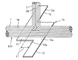
第1実施形態では、自動車に配索するワイヤハーネスW/Hの幹線1から枝線2がT字状に分岐する位置で、幹線1の電線群1Wおよび枝線2の電線群2Wを1枚の保護シート10で覆っている。
Hereinafter, embodiments of the present invention will be described in detail with reference to the drawings.
1 to 4 show a first embodiment.
In the first embodiment, one
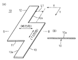
保護シート10はシートの一面に粘着材が塗布されて糊面10aとされたポリエチレン超延伸シートを図1(A)に示す形状に裁断している。該ポリエチレン超延伸シートとして積水成型工業株式会社製の登録商標「フォルテ」が好適に用いられる。該「フォルテ」からなるポリエチレン超延伸シートは分子配向方向(MD方向)に沿った方向は容易に屈曲する一方、該分子配向方向と直交する方向(TD方向)に難屈曲性を備え、かつ、三次元形状に折り曲げた状態で形状保持力を有する。また、厚さ0.4mm以上で、引張弾性率(GPa)が12以上、引張強度(MPa)が54以上で、金属板と同様な高強度、高剛性であり、しかも、比重が1以下で軽量である。本実施形態の保護シート10は厚さ0.4mmとしている。かつ、90度曲げで戻り角度が0゜〜3゜で殆ど曲げ戻りがなく、曲げた状態で形状を保持できる保形性に富んだ特性を有する。しかも、切断端が丸みを帯びてエッジが発生しないため、安全性が高い。
The
保護シート10は一面を糊面10aとして、電線群の外周に巻き付けた状態で形状保持力を有するため、糊面10aを電線群の外周面に押し付けて巻き付けるだけで、保護シート10を、従来のように粘着テープで巻き付けることなく、電線群に取り付けることができる。
Since the
保護シート10は、図1(A)に示すように、分子配向方向(MD方向)をワイヤハーネスの幹線1の電線群1Wの長さ方向に合わせた長方形状の本体部11と、該本体部11の長さ方向Xの両側に幅方向Yに突出させた重ね巻付部12、13を設けた形状としている。該重ね巻付部12は本体部11の幅方向Yの一方側へ突出させ、他方の重ね巻付部13は他方側に突出させている。両側の重ね巻付部12と13の長さ方向の間隔L1は枝線2の直径に対応させ、枝線2の直径方向の一側に重ね巻付部12の端縁12eが当接し、枝線2の他側に重ね巻付部13の端縁13eが当接する設定としている。
As shown in FIG. 1 (A), the
また、保護シート10の本体部11の幅方向Yの寸法は幹線1の外周長から枝線2の直径寸法を差し引いた寸法とし、かつ、長さ方向Xの寸法は枝線2の直径の3〜5倍程度としている。該保護シート10の本体部11の長さ方向Xの中央を幹線1から枝線2が分岐する位置に合わせると共に、幅方向Yの中央を枝線突出側と反対側の幹線連続側に位置させて、幹線1の外周に沿わせて本体部11を枝線突出側に向けて巻き付けると、枝線2の根元に本体部11の両側端縁が位置し、枝線2を挟む幹線1の両側で枝線2の直径寸法に対応する隙間をあけて本体部11が巻き付けられるようにしている。
The dimension of the
前記保護シート10を用いて幹線1から枝線2が分岐するT字分岐部を覆って保護する方法は、図3に示すように、糊面10aを幹線1の電線群1Wへの巻き付け面として、本体部11を電線群1Wの外周面に押し付けながら巻き付ける。この巻き付けは、前記のように、本体部11の長さ方向Xの中央を幹線1から枝線2が分岐する位置に合わせると共に、幅方向Yの中央を枝線突出側と反対側の幹線連続側に位置させて、幹線1の外周に沿わせて本体部11を枝線突出側に向けて巻き付ける。これにより、枝線2の根元に本体部11の両側端縁11e、11fが位置し、枝線2を挟む幹線1の両側で枝線2の直径寸法に対応する隙間C1、C2をあけて本体部11が巻き付けられ、糊面10aで電線群1Wに粘着する。
The method of covering and protecting the T-shaped branching portion where the
ついで、長さ方向の一方側の重ね巻付部12を隙間C1を覆った後に本体部11の長さ方向の一方側の外周面に巻き付け、重ね巻付部12の糊面で幹線1に巻き付けられている本体部11の外周面に粘着する。
同様に、長さ方向の他方側の重ね巻付部13を隙間C2を覆った後に本体部11の長さ方向の他方側の外周面に巻き付け、重ね巻付部13の糊面で幹線1に巻き付けられている本体部11の外周面に粘着する。
巻き付けた重ね巻付部12、13の長さ方向の端縁12e、13eは枝線2の電線群2Wの両側面に接する位置に粘着される。
Next, the overlapping winding
Similarly, the overlapping winding
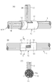
前記保護シート10の巻き付けにより、図4(A)〜(C)に示すように、ワイヤハーネスの分岐位置では幹線1の外周面は保護シート10で完全に覆われると共に、該幹線1から分岐する枝線2の根元は保護シート10で隙間なく覆われることになり、分岐部での電線群の露出を確実に阻止でき、電線群の保護と外観向上を図ることができる。
しかも、1枚の保護シート10を電線群に巻き付けるだけでよく、該保護シート10は巻き付け状態で自己保持できるため、粘着テープの巻き付けを不要にでき、作業手数および部品コストを削減することができる。
さらに、保護シート10は高剛性および高強度を有するため、分岐部での電線群の保護性能を高めることができる。
When the
Moreover, it is only necessary to wrap one
Furthermore, since the
図5に第1実施形態の変形例を示す。
変形例では、保護シート10の本体部11から突出する重ね巻付部12、13を幅方向Yの同一方向から突設している。該重ね巻付部12、13を本体部11の同じ幅方向端から突設しても、本体部11を幹線1に巻き付けた時に発生する隙間を塞ぐように重ね巻付部12、13を巻き付けることができる。
FIG. 5 shows a modification of the first embodiment.
In the modification, the overlapping winding
図6(A)(B)に第2実施形態を示す。
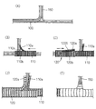
第2実施形態は図6(A)に示すワイヤハーネスの十字分岐部を保護シート10で保護している。
十字分岐部では幹線1の両側から枝線2A、2Bが分岐している。
保護シート10は第1実施形態と同一の「フォルテ」からなるポリエチレン超延伸シートを用い、形状も第1実施形態と略同様な形状とし、本体部11の長さ方向両側から重ね巻付部12、13が幅方向に突出している。
6A and 6B show a second embodiment.
In the second embodiment, the cross branch portion of the wire harness shown in FIG.
In the cross-branching portion,
The
本体部11の長さ方向および幅方向の中央に、枝線2Bを貫通させる穴15を設けており、この点を第1実施形態の保護シート10と相違させている。
A
保護シート10の穴15に一方の枝線2Bを通した後に、幹線1の外周面に本体部11を巻き付け、その後、重ね巻付部12、13を巻き付けてワイヤハーネスの分岐部を保護シート10で保護している。
これにより、十字分岐部も一枚の保護シート10で電線を露出させることなく保護することができる。
After passing one
Thereby, the cross-branching part can also be protected without exposing the electric wire with the single
1 幹線
2 枝線
10 保護シート
10a 糊面
11 本体部
12、13 重ね巻付部
DESCRIPTION OF
Claims (1)
前記保護シートを、分子配向方向をワイヤハーネスの電線群の長さ方向に合わせた長方形状の本体部と、該本体部の長さ方向の両側に幅方向に突出させた重ね巻付部を設けた形状とし、
ワイヤハーネスの分岐位置の枝線分岐側と反対側の幹線連続側に前記本体部の幅方向の中央部を巻き付けると共に幅方向の両側部を枝線を挟んで枝線分岐側に巻き付け、該本体部の内面側の前記糊面でワイヤハーネスの電線群に粘着し、かつ、
前記本体部の幅方向先端間の隙間を塞ぐように両側の前記重ね巻付部を前記本体部の外面に巻き付けて粘着しているワイヤハーネスの分岐部保護構造。 A polyethylene ultra-stretched sheet with an adhesive material coated on one side is used as a protective sheet. The protective sheet is easily bent in the direction along the molecular orientation direction (MD direction), but orthogonal to the molecular orientation direction. Having a bending resistance in the direction (TD direction) and having a shape retention force in a state of being folded into a three-dimensional shape,
The protective sheet is provided with a rectangular main body portion in which the molecular orientation direction is aligned with the length direction of the wire group of the wire harness, and a lap winding portion projecting in the width direction on both sides of the main body portion in the length direction. Shape
Wrapping the central part in the width direction of the main body part around the main line continuation side opposite to the branch line branch side of the branch position of the wire harness, and winding both sides in the width direction on the branch line branch side with the branch line interposed therebetween Adhering to the wire group of the wire harness with the glue surface on the inner surface side of the part, and
A branch protection structure for a wire harness in which the lap winding portions on both sides are wound around and adhered to the outer surface of the main body so as to close a gap between the front ends in the width direction of the main body.
Priority Applications (1)
| Application Number | Priority Date | Filing Date | Title |
|---|---|---|---|
| JP2015122726A JP2017011813A (en) | 2015-06-18 | 2015-06-18 | Branch part protection structure for wiring harness |
Applications Claiming Priority (1)
| Application Number | Priority Date | Filing Date | Title |
|---|---|---|---|
| JP2015122726A JP2017011813A (en) | 2015-06-18 | 2015-06-18 | Branch part protection structure for wiring harness |
Publications (1)
| Publication Number | Publication Date |
|---|---|
| JP2017011813A true JP2017011813A (en) | 2017-01-12 |
Family
ID=57764504
Family Applications (1)
| Application Number | Title | Priority Date | Filing Date |
|---|---|---|---|
| JP2015122726A Pending JP2017011813A (en) | 2015-06-18 | 2015-06-18 | Branch part protection structure for wiring harness |
Country Status (1)
| Country | Link |
|---|---|
| JP (1) | JP2017011813A (en) |
Cited By (6)
| Publication number | Priority date | Publication date | Assignee | Title |
|---|---|---|---|---|
| JP2019017198A (en) * | 2017-07-07 | 2019-01-31 | 矢崎総業株式会社 | Branch protector and wire harness |
| JP2019017200A (en) * | 2017-07-07 | 2019-01-31 | 矢崎総業株式会社 | Branch protector and wire harness |
| WO2019102760A1 (en) * | 2017-11-24 | 2019-05-31 | 住友電気工業株式会社 | Concentrating solar power generation device |
| CN111279566A (en) * | 2017-11-21 | 2020-06-12 | 古河电气工业株式会社 | Sheath for electric wire and wire harness having the same |
| CN112653038A (en) * | 2019-10-11 | 2021-04-13 | 矢崎总业株式会社 | Protective member for wire harness, and branch structure of wire harness |
| JP7382870B2 (en) | 2020-03-19 | 2023-11-17 | 古河電気工業株式会社 | Wire harness branch protection structure, protective sheet, and branch protection method |
-
2015
- 2015-06-18 JP JP2015122726A patent/JP2017011813A/en active Pending
Cited By (9)
| Publication number | Priority date | Publication date | Assignee | Title |
|---|---|---|---|---|
| JP2019017198A (en) * | 2017-07-07 | 2019-01-31 | 矢崎総業株式会社 | Branch protector and wire harness |
| JP2019017200A (en) * | 2017-07-07 | 2019-01-31 | 矢崎総業株式会社 | Branch protector and wire harness |
| CN111279566A (en) * | 2017-11-21 | 2020-06-12 | 古河电气工业株式会社 | Sheath for electric wire and wire harness having the same |
| US11837855B2 (en) | 2017-11-21 | 2023-12-05 | Furukawa Electric Co., Ltd. | Outer cover body for electrical wires and outer-cover-body-attached wire harness |
| WO2019102760A1 (en) * | 2017-11-24 | 2019-05-31 | 住友電気工業株式会社 | Concentrating solar power generation device |
| CN112653038A (en) * | 2019-10-11 | 2021-04-13 | 矢崎总业株式会社 | Protective member for wire harness, and branch structure of wire harness |
| EP3822126A1 (en) | 2019-10-11 | 2021-05-19 | Yazaki Corporation | Protective member for wire harness, and branching structure of wire harness |
| US11532408B2 (en) | 2019-10-11 | 2022-12-20 | Yazaki Corporation | Protective member for wire harness, and branching structure of wire harness |
| JP7382870B2 (en) | 2020-03-19 | 2023-11-17 | 古河電気工業株式会社 | Wire harness branch protection structure, protective sheet, and branch protection method |
Similar Documents
| Publication | Publication Date | Title |
|---|---|---|
| JP2017011813A (en) | Branch part protection structure for wiring harness | |
| US10614929B2 (en) | Wire harness sheet, wire harness, and method of manufacturing wire harness | |
| US9257822B2 (en) | Distribution structure of wire harness | |
| JP5824282B2 (en) | Wire harness | |
| EP3434531B1 (en) | Method for assembling wire harness, interference suppressing member, and wire harness assembly structure | |
| US9647434B2 (en) | Binding structure for band for wire harness | |
| WO2015060096A1 (en) | Heat-shrinkable slitted tube | |
| US9994169B2 (en) | Wire harness | |
| JP6002401B2 (en) | Wire harness and method of manufacturing wire harness | |
| WO2014141935A1 (en) | Affixation member and wire harness | |
| JP2009247070A (en) | Wiring harness branch protection sheet | |
| JP5915584B2 (en) | Wire harness branch protection sheet and wire harness | |
| JP2013225981A (en) | Protector for wire harness branch portion | |
| JP2015097432A (en) | Wiring harness | |
| JP2013255312A (en) | Protection structure for wire harness branch part | |
| JP6187204B2 (en) | Wire harness mounting method | |
| JP5083163B2 (en) | Wire harness | |
| JP3220854U (en) | Branch protection sheet for wire bundle or wire harness | |
| JP2012247678A (en) | Flexure regulation structure, and wire harness | |
| JP2011223702A (en) | In-vehicle electric wire fastener | |
| JP2014011824A (en) | Protective structure for wire harness terminal | |
| JP7107909B2 (en) | Wire harness branch protection member and wire harness branch structure | |
| JP2006254596A (en) | Protection structure of wire harness branching section, and forming method thereof | |
| JP2024011045A (en) | Wire harness and manufacturing method for the same | |
| WO2015060097A1 (en) | Heat-shrinkable slitted tube, and method for fastening heat-shrinkable slitted tube |