JP2017010932A - Power storage device and electronic device - Google Patents
Power storage device and electronic device Download PDFInfo
- Publication number
- JP2017010932A JP2017010932A JP2016116958A JP2016116958A JP2017010932A JP 2017010932 A JP2017010932 A JP 2017010932A JP 2016116958 A JP2016116958 A JP 2016116958A JP 2016116958 A JP2016116958 A JP 2016116958A JP 2017010932 A JP2017010932 A JP 2017010932A
- Authority
- JP
- Japan
- Prior art keywords
- power storage
- storage device
- film
- positive electrode
- negative electrode
- Prior art date
- Legal status (The legal status is an assumption and is not a legal conclusion. Google has not performed a legal analysis and makes no representation as to the accuracy of the status listed.)
- Withdrawn
Links
- 238000003860 storage Methods 0.000 title claims abstract description 276
- 239000010936 titanium Substances 0.000 claims abstract description 19
- 229910052719 titanium Inorganic materials 0.000 claims abstract description 17
- RTAQQCXQSZGOHL-UHFFFAOYSA-N Titanium Chemical compound [Ti] RTAQQCXQSZGOHL-UHFFFAOYSA-N 0.000 claims abstract description 16
- 239000010955 niobium Substances 0.000 claims abstract description 13
- 229910052758 niobium Inorganic materials 0.000 claims abstract description 12
- 229910052715 tantalum Inorganic materials 0.000 claims abstract description 12
- GUVRBAGPIYLISA-UHFFFAOYSA-N tantalum atom Chemical compound [Ta] GUVRBAGPIYLISA-UHFFFAOYSA-N 0.000 claims abstract description 12
- 229910052735 hafnium Inorganic materials 0.000 claims abstract description 11
- VBJZVLUMGGDVMO-UHFFFAOYSA-N hafnium atom Chemical compound [Hf] VBJZVLUMGGDVMO-UHFFFAOYSA-N 0.000 claims abstract description 11
- GUCVJGMIXFAOAE-UHFFFAOYSA-N niobium atom Chemical compound [Nb] GUCVJGMIXFAOAE-UHFFFAOYSA-N 0.000 claims abstract description 11
- 229910052720 vanadium Inorganic materials 0.000 claims abstract description 11
- LEONUFNNVUYDNQ-UHFFFAOYSA-N vanadium atom Chemical compound [V] LEONUFNNVUYDNQ-UHFFFAOYSA-N 0.000 claims abstract description 11
- QCWXUUIWCKQGHC-UHFFFAOYSA-N Zirconium Chemical compound [Zr] QCWXUUIWCKQGHC-UHFFFAOYSA-N 0.000 claims abstract description 10
- 229910052782 aluminium Inorganic materials 0.000 claims abstract description 10
- 229910052726 zirconium Inorganic materials 0.000 claims abstract description 10
- 239000011651 chromium Substances 0.000 claims abstract description 9
- XAGFODPZIPBFFR-UHFFFAOYSA-N aluminium Chemical compound [Al] XAGFODPZIPBFFR-UHFFFAOYSA-N 0.000 claims abstract description 8
- 229910052750 molybdenum Inorganic materials 0.000 claims abstract description 8
- ZOKXTWBITQBERF-UHFFFAOYSA-N Molybdenum Chemical compound [Mo] ZOKXTWBITQBERF-UHFFFAOYSA-N 0.000 claims abstract description 7
- 239000011733 molybdenum Substances 0.000 claims abstract description 7
- VYZAMTAEIAYCRO-UHFFFAOYSA-N Chromium Chemical compound [Cr] VYZAMTAEIAYCRO-UHFFFAOYSA-N 0.000 claims abstract description 6
- 229910052804 chromium Inorganic materials 0.000 claims abstract description 6
- 239000011368 organic material Substances 0.000 claims description 10
- 238000004806 packaging method and process Methods 0.000 abstract 2
- 239000010408 film Substances 0.000 description 101
- 239000010410 layer Substances 0.000 description 97
- OKTJSMMVPCPJKN-UHFFFAOYSA-N Carbon Chemical compound [C] OKTJSMMVPCPJKN-UHFFFAOYSA-N 0.000 description 58
- 229910021389 graphene Inorganic materials 0.000 description 49
- 239000007774 positive electrode material Substances 0.000 description 46
- 239000000463 material Substances 0.000 description 41
- -1 and a separator Substances 0.000 description 38
- 239000007773 negative electrode material Substances 0.000 description 35
- PXHVJJICTQNCMI-UHFFFAOYSA-N Nickel Chemical compound [Ni] PXHVJJICTQNCMI-UHFFFAOYSA-N 0.000 description 31
- 239000008151 electrolyte solution Substances 0.000 description 29
- 229910052744 lithium Inorganic materials 0.000 description 21
- 238000000034 method Methods 0.000 description 21
- XEEYBQQBJWHFJM-UHFFFAOYSA-N iron Substances [Fe] XEEYBQQBJWHFJM-UHFFFAOYSA-N 0.000 description 20
- 239000011572 manganese Substances 0.000 description 20
- WHXSMMKQMYFTQS-UHFFFAOYSA-N Lithium Chemical compound [Li] WHXSMMKQMYFTQS-UHFFFAOYSA-N 0.000 description 19
- 238000007600 charging Methods 0.000 description 18
- 230000000712 assembly Effects 0.000 description 16
- 238000000429 assembly Methods 0.000 description 16
- HBBGRARXTFLTSG-UHFFFAOYSA-N Lithium ion Chemical compound [Li+] HBBGRARXTFLTSG-UHFFFAOYSA-N 0.000 description 15
- 229910001416 lithium ion Inorganic materials 0.000 description 15
- 238000004519 manufacturing process Methods 0.000 description 15
- 229910052751 metal Inorganic materials 0.000 description 15
- 230000035882 stress Effects 0.000 description 15
- 230000006870 function Effects 0.000 description 13
- 229910002804 graphite Inorganic materials 0.000 description 13
- 239000010439 graphite Substances 0.000 description 13
- 239000002184 metal Substances 0.000 description 13
- 229910052799 carbon Inorganic materials 0.000 description 12
- 150000002500 ions Chemical class 0.000 description 11
- 239000004973 liquid crystal related substance Substances 0.000 description 11
- 238000006243 chemical reaction Methods 0.000 description 10
- 239000013078 crystal Substances 0.000 description 10
- 239000003792 electrolyte Substances 0.000 description 10
- 229910052759 nickel Inorganic materials 0.000 description 10
- 229910052710 silicon Inorganic materials 0.000 description 10
- 239000011149 active material Substances 0.000 description 9
- 125000004429 atom Chemical group 0.000 description 9
- 229910004283 SiO 4 Inorganic materials 0.000 description 8
- 150000001875 compounds Chemical class 0.000 description 8
- 239000007789 gas Substances 0.000 description 8
- 239000004065 semiconductor Substances 0.000 description 8
- XUIMIQQOPSSXEZ-UHFFFAOYSA-N Silicon Chemical compound [Si] XUIMIQQOPSSXEZ-UHFFFAOYSA-N 0.000 description 7
- 238000005452 bending Methods 0.000 description 7
- 238000007789 sealing Methods 0.000 description 7
- 239000010703 silicon Substances 0.000 description 7
- 229910013716 LiNi Inorganic materials 0.000 description 6
- QVGXLLKOCUKJST-UHFFFAOYSA-N atomic oxygen Chemical compound [O] QVGXLLKOCUKJST-UHFFFAOYSA-N 0.000 description 6
- 230000004888 barrier function Effects 0.000 description 6
- 239000011230 binding agent Substances 0.000 description 6
- 239000002482 conductive additive Substances 0.000 description 6
- 239000010949 copper Substances 0.000 description 6
- 150000004767 nitrides Chemical class 0.000 description 6
- 229910052760 oxygen Inorganic materials 0.000 description 6
- 239000001301 oxygen Substances 0.000 description 6
- 239000010409 thin film Substances 0.000 description 6
- HEZMWWAKWCSUCB-PHDIDXHHSA-N (3R,4R)-3,4-dihydroxycyclohexa-1,5-diene-1-carboxylic acid Chemical compound O[C@@H]1C=CC(C(O)=O)=C[C@H]1O HEZMWWAKWCSUCB-PHDIDXHHSA-N 0.000 description 5
- 239000004698 Polyethylene Substances 0.000 description 5
- 239000000956 alloy Substances 0.000 description 5
- 239000003990 capacitor Substances 0.000 description 5
- 229910052742 iron Inorganic materials 0.000 description 5
- 229910052748 manganese Inorganic materials 0.000 description 5
- 229920002647 polyamide Polymers 0.000 description 5
- 229920000573 polyethylene Polymers 0.000 description 5
- 229920000642 polymer Polymers 0.000 description 5
- 239000011734 sodium Substances 0.000 description 5
- 239000002904 solvent Substances 0.000 description 5
- UQSXHKLRYXJYBZ-UHFFFAOYSA-N Iron oxide Chemical compound [Fe]=O UQSXHKLRYXJYBZ-UHFFFAOYSA-N 0.000 description 4
- 229910013290 LiNiO 2 Inorganic materials 0.000 description 4
- 239000002033 PVDF binder Substances 0.000 description 4
- 239000004743 Polypropylene Substances 0.000 description 4
- 229910007746 Zr—O Inorganic materials 0.000 description 4
- 239000006230 acetylene black Substances 0.000 description 4
- 229910045601 alloy Inorganic materials 0.000 description 4
- 239000002041 carbon nanotube Substances 0.000 description 4
- 229910021393 carbon nanotube Inorganic materials 0.000 description 4
- 229910052802 copper Inorganic materials 0.000 description 4
- 230000000694 effects Effects 0.000 description 4
- 229910052749 magnesium Inorganic materials 0.000 description 4
- 239000011777 magnesium Substances 0.000 description 4
- 239000000203 mixture Substances 0.000 description 4
- BASFCYQUMIYNBI-UHFFFAOYSA-N platinum Chemical compound [Pt] BASFCYQUMIYNBI-UHFFFAOYSA-N 0.000 description 4
- 229920001155 polypropylene Polymers 0.000 description 4
- 229920002981 polyvinylidene fluoride Polymers 0.000 description 4
- 230000008569 process Effects 0.000 description 4
- 229910021332 silicide Inorganic materials 0.000 description 4
- FVBUAEGBCNSCDD-UHFFFAOYSA-N silicide(4-) Chemical compound [Si-4] FVBUAEGBCNSCDD-UHFFFAOYSA-N 0.000 description 4
- 229910052708 sodium Inorganic materials 0.000 description 4
- 239000000126 substance Substances 0.000 description 4
- 239000011701 zinc Substances 0.000 description 4
- WEVYAHXRMPXWCK-UHFFFAOYSA-N Acetonitrile Chemical compound CC#N WEVYAHXRMPXWCK-UHFFFAOYSA-N 0.000 description 3
- OYPRJOBELJOOCE-UHFFFAOYSA-N Calcium Chemical compound [Ca] OYPRJOBELJOOCE-UHFFFAOYSA-N 0.000 description 3
- RYGMFSIKBFXOCR-UHFFFAOYSA-N Copper Chemical compound [Cu] RYGMFSIKBFXOCR-UHFFFAOYSA-N 0.000 description 3
- RTZKZFJDLAIYFH-UHFFFAOYSA-N Diethyl ether Chemical compound CCOCC RTZKZFJDLAIYFH-UHFFFAOYSA-N 0.000 description 3
- DGAQECJNVWCQMB-PUAWFVPOSA-M Ilexoside XXIX Chemical compound C[C@@H]1CC[C@@]2(CC[C@@]3(C(=CC[C@H]4[C@]3(CC[C@@H]5[C@@]4(CC[C@@H](C5(C)C)OS(=O)(=O)[O-])C)C)[C@@H]2[C@]1(C)O)C)C(=O)O[C@H]6[C@@H]([C@H]([C@@H]([C@H](O6)CO)O)O)O.[Na+] DGAQECJNVWCQMB-PUAWFVPOSA-M 0.000 description 3
- 229910013870 LiPF 6 Inorganic materials 0.000 description 3
- 239000004952 Polyamide Substances 0.000 description 3
- 229910004298 SiO 2 Inorganic materials 0.000 description 3
- VYPSYNLAJGMNEJ-UHFFFAOYSA-N Silicium dioxide Chemical compound O=[Si]=O VYPSYNLAJGMNEJ-UHFFFAOYSA-N 0.000 description 3
- 230000009471 action Effects 0.000 description 3
- 230000032683 aging Effects 0.000 description 3
- 229910021383 artificial graphite Inorganic materials 0.000 description 3
- 229910052791 calcium Inorganic materials 0.000 description 3
- 239000011575 calcium Substances 0.000 description 3
- 239000000470 constituent Substances 0.000 description 3
- 238000005520 cutting process Methods 0.000 description 3
- 229910052731 fluorine Inorganic materials 0.000 description 3
- 239000011888 foil Substances 0.000 description 3
- 125000000524 functional group Chemical group 0.000 description 3
- 210000004247 hand Anatomy 0.000 description 3
- 150000002739 metals Chemical class 0.000 description 3
- 230000003287 optical effect Effects 0.000 description 3
- 239000000123 paper Substances 0.000 description 3
- 239000002245 particle Substances 0.000 description 3
- 229920003229 poly(methyl methacrylate) Polymers 0.000 description 3
- 239000002861 polymer material Substances 0.000 description 3
- 239000004926 polymethyl methacrylate Substances 0.000 description 3
- 238000010248 power generation Methods 0.000 description 3
- 229910052709 silver Inorganic materials 0.000 description 3
- 235000002639 sodium chloride Nutrition 0.000 description 3
- 229910052596 spinel Inorganic materials 0.000 description 3
- 239000011029 spinel Substances 0.000 description 3
- 239000010935 stainless steel Substances 0.000 description 3
- 229910001220 stainless steel Inorganic materials 0.000 description 3
- 229910052723 transition metal Inorganic materials 0.000 description 3
- 150000003624 transition metals Chemical class 0.000 description 3
- 229910052721 tungsten Inorganic materials 0.000 description 3
- 238000003466 welding Methods 0.000 description 3
- 229910052725 zinc Inorganic materials 0.000 description 3
- VAYTZRYEBVHVLE-UHFFFAOYSA-N 1,3-dioxol-2-one Chemical compound O=C1OC=CO1 VAYTZRYEBVHVLE-UHFFFAOYSA-N 0.000 description 2
- YEJRWHAVMIAJKC-UHFFFAOYSA-N 4-Butyrolactone Chemical compound O=C1CCCO1 YEJRWHAVMIAJKC-UHFFFAOYSA-N 0.000 description 2
- IJGRMHOSHXDMSA-UHFFFAOYSA-N Atomic nitrogen Chemical compound N#N IJGRMHOSHXDMSA-UHFFFAOYSA-N 0.000 description 2
- XMWRBQBLMFGWIX-UHFFFAOYSA-N C60 fullerene Chemical compound C12=C3C(C4=C56)=C7C8=C5C5=C9C%10=C6C6=C4C1=C1C4=C6C6=C%10C%10=C9C9=C%11C5=C8C5=C8C7=C3C3=C7C2=C1C1=C2C4=C6C4=C%10C6=C9C9=C%11C5=C5C8=C3C3=C7C1=C1C2=C4C6=C2C9=C5C3=C12 XMWRBQBLMFGWIX-UHFFFAOYSA-N 0.000 description 2
- XTHFKEDIFFGKHM-UHFFFAOYSA-N Dimethoxyethane Chemical compound COCCOC XTHFKEDIFFGKHM-UHFFFAOYSA-N 0.000 description 2
- IAZDPXIOMUYVGZ-UHFFFAOYSA-N Dimethylsulphoxide Chemical compound CS(C)=O IAZDPXIOMUYVGZ-UHFFFAOYSA-N 0.000 description 2
- KMTRUDSVKNLOMY-UHFFFAOYSA-N Ethylene carbonate Chemical compound O=C1OCCO1 KMTRUDSVKNLOMY-UHFFFAOYSA-N 0.000 description 2
- YCKRFDGAMUMZLT-UHFFFAOYSA-N Fluorine atom Chemical compound [F] YCKRFDGAMUMZLT-UHFFFAOYSA-N 0.000 description 2
- 229910012851 LiCoO 2 Inorganic materials 0.000 description 2
- 229910010707 LiFePO 4 Inorganic materials 0.000 description 2
- 229910015643 LiMn 2 O 4 Inorganic materials 0.000 description 2
- 229910015868 MSiO Inorganic materials 0.000 description 2
- FYYHWMGAXLPEAU-UHFFFAOYSA-N Magnesium Chemical compound [Mg] FYYHWMGAXLPEAU-UHFFFAOYSA-N 0.000 description 2
- PWHULOQIROXLJO-UHFFFAOYSA-N Manganese Chemical compound [Mn] PWHULOQIROXLJO-UHFFFAOYSA-N 0.000 description 2
- 239000002228 NASICON Substances 0.000 description 2
- 239000000020 Nitrocellulose Substances 0.000 description 2
- 229920003171 Poly (ethylene oxide) Polymers 0.000 description 2
- 239000004642 Polyimide Substances 0.000 description 2
- 239000004372 Polyvinyl alcohol Substances 0.000 description 2
- 241000156302 Porcine hemagglutinating encephalomyelitis virus Species 0.000 description 2
- ZLMJMSJWJFRBEC-UHFFFAOYSA-N Potassium Chemical compound [K] ZLMJMSJWJFRBEC-UHFFFAOYSA-N 0.000 description 2
- FAPWRFPIFSIZLT-UHFFFAOYSA-M Sodium chloride Chemical compound [Na+].[Cl-] FAPWRFPIFSIZLT-UHFFFAOYSA-M 0.000 description 2
- WYURNTSHIVDZCO-UHFFFAOYSA-N Tetrahydrofuran Chemical compound C1CCOC1 WYURNTSHIVDZCO-UHFFFAOYSA-N 0.000 description 2
- 229910001069 Ti alloy Inorganic materials 0.000 description 2
- 238000000560 X-ray reflectometry Methods 0.000 description 2
- HCHKCACWOHOZIP-UHFFFAOYSA-N Zinc Chemical compound [Zn] HCHKCACWOHOZIP-UHFFFAOYSA-N 0.000 description 2
- 230000001133 acceleration Effects 0.000 description 2
- NIXOWILDQLNWCW-UHFFFAOYSA-N acrylic acid group Chemical group C(C=C)(=O)O NIXOWILDQLNWCW-UHFFFAOYSA-N 0.000 description 2
- 229910052783 alkali metal Inorganic materials 0.000 description 2
- 229910001413 alkali metal ion Inorganic materials 0.000 description 2
- 150000001340 alkali metals Chemical class 0.000 description 2
- 229910052784 alkaline earth metal Inorganic materials 0.000 description 2
- 229910001420 alkaline earth metal ion Inorganic materials 0.000 description 2
- 150000001342 alkaline earth metals Chemical class 0.000 description 2
- 125000000217 alkyl group Chemical group 0.000 description 2
- 238000005275 alloying Methods 0.000 description 2
- 229910052787 antimony Inorganic materials 0.000 description 2
- 239000012752 auxiliary agent Substances 0.000 description 2
- 229910052788 barium Inorganic materials 0.000 description 2
- DSAJWYNOEDNPEQ-UHFFFAOYSA-N barium atom Chemical compound [Ba] DSAJWYNOEDNPEQ-UHFFFAOYSA-N 0.000 description 2
- 230000008901 benefit Effects 0.000 description 2
- 229910052790 beryllium Inorganic materials 0.000 description 2
- ATBAMAFKBVZNFJ-UHFFFAOYSA-N beryllium atom Chemical compound [Be] ATBAMAFKBVZNFJ-UHFFFAOYSA-N 0.000 description 2
- 230000005540 biological transmission Effects 0.000 description 2
- 229910052793 cadmium Inorganic materials 0.000 description 2
- 125000004432 carbon atom Chemical group C* 0.000 description 2
- 238000000576 coating method Methods 0.000 description 2
- 229910017052 cobalt Inorganic materials 0.000 description 2
- 239000010941 cobalt Substances 0.000 description 2
- GUTLYIVDDKVIGB-UHFFFAOYSA-N cobalt atom Chemical compound [Co] GUTLYIVDDKVIGB-UHFFFAOYSA-N 0.000 description 2
- 238000004891 communication Methods 0.000 description 2
- 230000007423 decrease Effects 0.000 description 2
- 230000006866 deterioration Effects 0.000 description 2
- 238000010586 diagram Methods 0.000 description 2
- 239000002612 dispersion medium Substances 0.000 description 2
- JBTWLSYIZRCDFO-UHFFFAOYSA-N ethyl methyl carbonate Chemical compound CCOC(=O)OC JBTWLSYIZRCDFO-UHFFFAOYSA-N 0.000 description 2
- 239000011737 fluorine Substances 0.000 description 2
- 229910003472 fullerene Inorganic materials 0.000 description 2
- 230000004927 fusion Effects 0.000 description 2
- GAEKPEKOJKCEMS-UHFFFAOYSA-N gamma-valerolactone Chemical compound CC1CCC(=O)O1 GAEKPEKOJKCEMS-UHFFFAOYSA-N 0.000 description 2
- 229910052732 germanium Inorganic materials 0.000 description 2
- 239000003365 glass fiber Substances 0.000 description 2
- PCHJSUWPFVWCPO-UHFFFAOYSA-N gold Chemical compound [Au] PCHJSUWPFVWCPO-UHFFFAOYSA-N 0.000 description 2
- 229910052737 gold Inorganic materials 0.000 description 2
- 239000010931 gold Substances 0.000 description 2
- 235000019589 hardness Nutrition 0.000 description 2
- AMWRITDGCCNYAT-UHFFFAOYSA-L hydroxy(oxo)manganese;manganese Chemical compound [Mn].O[Mn]=O.O[Mn]=O AMWRITDGCCNYAT-UHFFFAOYSA-L 0.000 description 2
- 239000012535 impurity Substances 0.000 description 2
- 238000009413 insulation Methods 0.000 description 2
- 229920000554 ionomer Polymers 0.000 description 2
- 239000007788 liquid Substances 0.000 description 2
- AMXOYNBUYSYVKV-UHFFFAOYSA-M lithium bromide Chemical compound [Li+].[Br-] AMXOYNBUYSYVKV-UHFFFAOYSA-M 0.000 description 2
- 229910003002 lithium salt Inorganic materials 0.000 description 2
- 159000000002 lithium salts Chemical class 0.000 description 2
- 239000012528 membrane Substances 0.000 description 2
- 239000002931 mesocarbon microbead Substances 0.000 description 2
- TZIHFWKZFHZASV-UHFFFAOYSA-N methyl formate Chemical compound COC=O TZIHFWKZFHZASV-UHFFFAOYSA-N 0.000 description 2
- 229910021382 natural graphite Inorganic materials 0.000 description 2
- 229910000480 nickel oxide Inorganic materials 0.000 description 2
- 229920001220 nitrocellulos Polymers 0.000 description 2
- 229910052757 nitrogen Inorganic materials 0.000 description 2
- 239000004745 nonwoven fabric Substances 0.000 description 2
- 239000010450 olivine Substances 0.000 description 2
- 229910052609 olivine Inorganic materials 0.000 description 2
- 230000001151 other effect Effects 0.000 description 2
- 229910052697 platinum Inorganic materials 0.000 description 2
- 229920000515 polycarbonate Polymers 0.000 description 2
- 239000004417 polycarbonate Substances 0.000 description 2
- 229920001225 polyester resin Polymers 0.000 description 2
- 229920001721 polyimide Polymers 0.000 description 2
- 229920000098 polyolefin Polymers 0.000 description 2
- 229920001451 polypropylene glycol Polymers 0.000 description 2
- 229920002635 polyurethane Polymers 0.000 description 2
- 239000004814 polyurethane Substances 0.000 description 2
- 229920002689 polyvinyl acetate Polymers 0.000 description 2
- 239000011118 polyvinyl acetate Substances 0.000 description 2
- 229920002451 polyvinyl alcohol Polymers 0.000 description 2
- 239000004800 polyvinyl chloride Substances 0.000 description 2
- 229920000915 polyvinyl chloride Polymers 0.000 description 2
- 229910052700 potassium Inorganic materials 0.000 description 2
- 239000011591 potassium Substances 0.000 description 2
- 238000002360 preparation method Methods 0.000 description 2
- 238000012545 processing Methods 0.000 description 2
- RUOJZAUFBMNUDX-UHFFFAOYSA-N propylene carbonate Chemical compound CC1COC(=O)O1 RUOJZAUFBMNUDX-UHFFFAOYSA-N 0.000 description 2
- 238000004080 punching Methods 0.000 description 2
- 229920005989 resin Polymers 0.000 description 2
- 239000011347 resin Substances 0.000 description 2
- 238000005001 rutherford backscattering spectroscopy Methods 0.000 description 2
- 229920002050 silicone resin Polymers 0.000 description 2
- NDVLTYZPCACLMA-UHFFFAOYSA-N silver oxide Chemical compound [O-2].[Ag+].[Ag+] NDVLTYZPCACLMA-UHFFFAOYSA-N 0.000 description 2
- 239000002356 single layer Substances 0.000 description 2
- 239000011780 sodium chloride Substances 0.000 description 2
- 239000006104 solid solution Substances 0.000 description 2
- 229910052712 strontium Inorganic materials 0.000 description 2
- CIOAGBVUUVVLOB-UHFFFAOYSA-N strontium atom Chemical compound [Sr] CIOAGBVUUVVLOB-UHFFFAOYSA-N 0.000 description 2
- 125000001424 substituent group Chemical group 0.000 description 2
- 150000004763 sulfides Chemical class 0.000 description 2
- 230000001629 suppression Effects 0.000 description 2
- 229920003002 synthetic resin Polymers 0.000 description 2
- 239000000057 synthetic resin Substances 0.000 description 2
- 229910052718 tin Inorganic materials 0.000 description 2
- 230000009466 transformation Effects 0.000 description 2
- WFKWXMTUELFFGS-UHFFFAOYSA-N tungsten Chemical compound [W] WFKWXMTUELFFGS-UHFFFAOYSA-N 0.000 description 2
- 239000010937 tungsten Substances 0.000 description 2
- ZZXUZKXVROWEIF-UHFFFAOYSA-N 1,2-butylene carbonate Chemical compound CCC1COC(=O)O1 ZZXUZKXVROWEIF-UHFFFAOYSA-N 0.000 description 1
- VDFVNEFVBPFDSB-UHFFFAOYSA-N 1,3-dioxane Chemical compound C1COCOC1 VDFVNEFVBPFDSB-UHFFFAOYSA-N 0.000 description 1
- RYHBNJHYFVUHQT-UHFFFAOYSA-N 1,4-Dioxane Chemical compound C1COCCO1 RYHBNJHYFVUHQT-UHFFFAOYSA-N 0.000 description 1
- RNFJDJUURJAICM-UHFFFAOYSA-N 2,2,4,4,6,6-hexaphenoxy-1,3,5-triaza-2$l^{5},4$l^{5},6$l^{5}-triphosphacyclohexa-1,3,5-triene Chemical compound N=1P(OC=2C=CC=CC=2)(OC=2C=CC=CC=2)=NP(OC=2C=CC=CC=2)(OC=2C=CC=CC=2)=NP=1(OC=1C=CC=CC=1)OC1=CC=CC=C1 RNFJDJUURJAICM-UHFFFAOYSA-N 0.000 description 1
- OYOKPDLAMOMTEE-UHFFFAOYSA-N 4-chloro-1,3-dioxolan-2-one Chemical compound ClC1COC(=O)O1 OYOKPDLAMOMTEE-UHFFFAOYSA-N 0.000 description 1
- NLHHRLWOUZZQLW-UHFFFAOYSA-N Acrylonitrile Chemical compound C=CC#N NLHHRLWOUZZQLW-UHFFFAOYSA-N 0.000 description 1
- 102100031786 Adiponectin Human genes 0.000 description 1
- 229910000838 Al alloy Inorganic materials 0.000 description 1
- 229910018989 CoSb Inorganic materials 0.000 description 1
- 229910019043 CoSn Inorganic materials 0.000 description 1
- 229910017482 Cu 6 Sn 5 Inorganic materials 0.000 description 1
- OIFBSDVPJOWBCH-UHFFFAOYSA-N Diethyl carbonate Chemical compound CCOC(=O)OCC OIFBSDVPJOWBCH-UHFFFAOYSA-N 0.000 description 1
- 229910005382 FeSn Inorganic materials 0.000 description 1
- KRHYYFGTRYWZRS-UHFFFAOYSA-M Fluoride anion Chemical compound [F-] KRHYYFGTRYWZRS-UHFFFAOYSA-M 0.000 description 1
- 101000775469 Homo sapiens Adiponectin Proteins 0.000 description 1
- UFHFLCQGNIYNRP-UHFFFAOYSA-N Hydrogen Chemical compound [H][H] UFHFLCQGNIYNRP-UHFFFAOYSA-N 0.000 description 1
- 206010020751 Hypersensitivity Diseases 0.000 description 1
- JGFBQFKZKSSODQ-UHFFFAOYSA-N Isothiocyanatocyclopropane Chemical compound S=C=NC1CC1 JGFBQFKZKSSODQ-UHFFFAOYSA-N 0.000 description 1
- 229910018122 Li 3-x M Inorganic materials 0.000 description 1
- 229910004424 Li(Ni0.8Co0.15Al0.05)O2 Inorganic materials 0.000 description 1
- 229910008163 Li1+x Mn2-x O4 Inorganic materials 0.000 description 1
- 229910011939 Li2.6 Co0.4 N Inorganic materials 0.000 description 1
- 229910010085 Li2MnO3-LiMO2 Inorganic materials 0.000 description 1
- 229910010099 Li2MnO3—LiMO2 Inorganic materials 0.000 description 1
- 229910012425 Li3Fe2 (PO4)3 Inorganic materials 0.000 description 1
- 229910010238 LiAlCl 4 Inorganic materials 0.000 description 1
- 229910015015 LiAsF 6 Inorganic materials 0.000 description 1
- 229910013063 LiBF 4 Inorganic materials 0.000 description 1
- 229910013372 LiC 4 Inorganic materials 0.000 description 1
- 229910013684 LiClO 4 Inorganic materials 0.000 description 1
- 229910012733 LiCo1/3Mn1/3Ni1/3O2 Inorganic materials 0.000 description 1
- 229910011281 LiCoPO 4 Inorganic materials 0.000 description 1
- 229910013275 LiMPO Inorganic materials 0.000 description 1
- 229910015645 LiMn Inorganic materials 0.000 description 1
- 229910016118 LiMn1.5Ni0.5O4 Inorganic materials 0.000 description 1
- 229910014689 LiMnO Inorganic materials 0.000 description 1
- 229910013709 LiNi 1-x M Inorganic materials 0.000 description 1
- 229910012752 LiNi0.5Mn0.5O2 Inorganic materials 0.000 description 1
- 229910015915 LiNi0.8Co0.2O2 Inorganic materials 0.000 description 1
- 229910014422 LiNi1/3Mn1/3Co1/3O2 Inorganic materials 0.000 description 1
- 229910013086 LiNiPO Inorganic materials 0.000 description 1
- 229910019018 Mg 2 Si Inorganic materials 0.000 description 1
- 229910019021 Mg 2 Sn Inorganic materials 0.000 description 1
- 229910016964 MnSb Inorganic materials 0.000 description 1
- 229910021314 NaFeO 2 Inorganic materials 0.000 description 1
- 229910052779 Neodymium Inorganic materials 0.000 description 1
- 229910003266 NiCo Inorganic materials 0.000 description 1
- 229910003289 NiMn Inorganic materials 0.000 description 1
- 229910005800 NiMnCo Inorganic materials 0.000 description 1
- 229920000459 Nitrile rubber Polymers 0.000 description 1
- 239000004677 Nylon Substances 0.000 description 1
- 229920002319 Poly(methyl acrylate) Polymers 0.000 description 1
- 239000005062 Polybutadiene Substances 0.000 description 1
- 229920002873 Polyethylenimine Polymers 0.000 description 1
- 239000004721 Polyphenylene oxide Substances 0.000 description 1
- 239000004793 Polystyrene Substances 0.000 description 1
- 229920001328 Polyvinylidene chloride Polymers 0.000 description 1
- XBDQKXXYIPTUBI-UHFFFAOYSA-M Propionate Chemical compound CCC([O-])=O XBDQKXXYIPTUBI-UHFFFAOYSA-M 0.000 description 1
- 229910018320 SbSn Inorganic materials 0.000 description 1
- 229910006404 SnO 2 Inorganic materials 0.000 description 1
- GWEVSGVZZGPLCZ-UHFFFAOYSA-N Titan oxide Chemical compound O=[Ti]=O GWEVSGVZZGPLCZ-UHFFFAOYSA-N 0.000 description 1
- 229920002978 Vinylon Polymers 0.000 description 1
- XHCLAFWTIXFWPH-UHFFFAOYSA-N [O-2].[O-2].[O-2].[O-2].[O-2].[V+5].[V+5] Chemical class [O-2].[O-2].[O-2].[O-2].[O-2].[V+5].[V+5] XHCLAFWTIXFWPH-UHFFFAOYSA-N 0.000 description 1
- FDLZQPXZHIFURF-UHFFFAOYSA-N [O-2].[Ti+4].[Li+] Chemical compound [O-2].[Ti+4].[Li+] FDLZQPXZHIFURF-UHFFFAOYSA-N 0.000 description 1
- KXKVLQRXCPHEJC-UHFFFAOYSA-N acetic acid trimethyl ester Natural products COC(C)=O KXKVLQRXCPHEJC-UHFFFAOYSA-N 0.000 description 1
- 239000000654 additive Substances 0.000 description 1
- 208000030961 allergic reaction Diseases 0.000 description 1
- 229910021417 amorphous silicon Inorganic materials 0.000 description 1
- 239000006183 anode active material Substances 0.000 description 1
- 239000007864 aqueous solution Substances 0.000 description 1
- 229910052785 arsenic Inorganic materials 0.000 description 1
- 125000005605 benzo group Chemical group 0.000 description 1
- 229910052797 bismuth Inorganic materials 0.000 description 1
- PWLNAUNEAKQYLH-UHFFFAOYSA-N butyric acid octyl ester Natural products CCCCCCCCOC(=O)CCC PWLNAUNEAKQYLH-UHFFFAOYSA-N 0.000 description 1
- BDOSMKKIYDKNTQ-UHFFFAOYSA-N cadmium atom Chemical compound [Cd] BDOSMKKIYDKNTQ-UHFFFAOYSA-N 0.000 description 1
- 239000006229 carbon black Substances 0.000 description 1
- 239000003575 carbonaceous material Substances 0.000 description 1
- 125000002915 carbonyl group Chemical group [*:2]C([*:1])=O 0.000 description 1
- 125000003178 carboxy group Chemical group [H]OC(*)=O 0.000 description 1
- 230000001413 cellular effect Effects 0.000 description 1
- 229920002678 cellulose Polymers 0.000 description 1
- 239000001913 cellulose Substances 0.000 description 1
- 239000000919 ceramic Substances 0.000 description 1
- 150000004770 chalcogenides Chemical class 0.000 description 1
- 230000008859 change Effects 0.000 description 1
- 239000007795 chemical reaction product Substances 0.000 description 1
- IVMYJDGYRUAWML-UHFFFAOYSA-N cobalt(ii) oxide Chemical compound [Co]=O IVMYJDGYRUAWML-UHFFFAOYSA-N 0.000 description 1
- 239000000571 coke Substances 0.000 description 1
- 239000002131 composite material Substances 0.000 description 1
- 238000010277 constant-current charging Methods 0.000 description 1
- 238000010276 construction Methods 0.000 description 1
- 230000007797 corrosion Effects 0.000 description 1
- 238000005260 corrosion Methods 0.000 description 1
- 238000000354 decomposition reaction Methods 0.000 description 1
- 238000001514 detection method Methods 0.000 description 1
- SBZXBUIDTXKZTM-UHFFFAOYSA-N diglyme Chemical compound COCCOCCOC SBZXBUIDTXKZTM-UHFFFAOYSA-N 0.000 description 1
- IEJIGPNLZYLLBP-UHFFFAOYSA-N dimethyl carbonate Chemical compound COC(=O)OC IEJIGPNLZYLLBP-UHFFFAOYSA-N 0.000 description 1
- QXYJCZRRLLQGCR-UHFFFAOYSA-N dioxomolybdenum Chemical compound O=[Mo]=O QXYJCZRRLLQGCR-UHFFFAOYSA-N 0.000 description 1
- 238000007599 discharging Methods 0.000 description 1
- 238000006073 displacement reaction Methods 0.000 description 1
- 238000001035 drying Methods 0.000 description 1
- 239000000428 dust Substances 0.000 description 1
- 229920001971 elastomer Polymers 0.000 description 1
- 230000005684 electric field Effects 0.000 description 1
- 239000011267 electrode slurry Substances 0.000 description 1
- 238000005401 electroluminescence Methods 0.000 description 1
- 230000005674 electromagnetic induction Effects 0.000 description 1
- 238000010828 elution Methods 0.000 description 1
- 238000005516 engineering process Methods 0.000 description 1
- 125000003700 epoxy group Chemical group 0.000 description 1
- 239000000835 fiber Substances 0.000 description 1
- 238000010304 firing Methods 0.000 description 1
- 239000003063 flame retardant Substances 0.000 description 1
- 150000002222 fluorine compounds Chemical class 0.000 description 1
- 229920001973 fluoroelastomer Polymers 0.000 description 1
- 229920002313 fluoropolymer Polymers 0.000 description 1
- 239000004811 fluoropolymer Substances 0.000 description 1
- 229910052733 gallium Inorganic materials 0.000 description 1
- 229910021469 graphitizable carbon Inorganic materials 0.000 description 1
- 229910021385 hard carbon Inorganic materials 0.000 description 1
- 230000003862 health status Effects 0.000 description 1
- 229910052739 hydrogen Inorganic materials 0.000 description 1
- 239000001257 hydrogen Substances 0.000 description 1
- 125000002887 hydroxy group Chemical group [H]O* 0.000 description 1
- 238000003384 imaging method Methods 0.000 description 1
- 230000001771 impaired effect Effects 0.000 description 1
- 229910052738 indium Inorganic materials 0.000 description 1
- WPYVAWXEWQSOGY-UHFFFAOYSA-N indium antimonide Chemical compound [Sb]#[In] WPYVAWXEWQSOGY-UHFFFAOYSA-N 0.000 description 1
- 239000011261 inert gas Substances 0.000 description 1
- 238000012905 input function Methods 0.000 description 1
- 230000002687 intercalation Effects 0.000 description 1
- 238000009830 intercalation Methods 0.000 description 1
- 239000002608 ionic liquid Substances 0.000 description 1
- 230000002427 irreversible effect Effects 0.000 description 1
- 238000005304 joining Methods 0.000 description 1
- 239000005001 laminate film Substances 0.000 description 1
- 238000003475 lamination Methods 0.000 description 1
- 229910052745 lead Inorganic materials 0.000 description 1
- GELKBWJHTRAYNV-UHFFFAOYSA-K lithium iron phosphate Chemical compound [Li+].[Fe+2].[O-]P([O-])([O-])=O GELKBWJHTRAYNV-UHFFFAOYSA-K 0.000 description 1
- ACFSQHQYDZIPRL-UHFFFAOYSA-N lithium;bis(1,1,2,2,2-pentafluoroethylsulfonyl)azanide Chemical compound [Li+].FC(F)(F)C(F)(F)S(=O)(=O)[N-]S(=O)(=O)C(F)(F)C(F)(F)F ACFSQHQYDZIPRL-UHFFFAOYSA-N 0.000 description 1
- 230000005389 magnetism Effects 0.000 description 1
- WPBNNNQJVZRUHP-UHFFFAOYSA-L manganese(2+);methyl n-[[2-(methoxycarbonylcarbamothioylamino)phenyl]carbamothioyl]carbamate;n-[2-(sulfidocarbothioylamino)ethyl]carbamodithioate Chemical compound [Mn+2].[S-]C(=S)NCCNC([S-])=S.COC(=O)NC(=S)NC1=CC=CC=C1NC(=S)NC(=O)OC WPBNNNQJVZRUHP-UHFFFAOYSA-L 0.000 description 1
- 239000002609 medium Substances 0.000 description 1
- 239000000155 melt Substances 0.000 description 1
- 238000002156 mixing Methods 0.000 description 1
- 229910021421 monocrystalline silicon Inorganic materials 0.000 description 1
- UUIQMZJEGPQKFD-UHFFFAOYSA-N n-butyric acid methyl ester Natural products CCCC(=O)OC UUIQMZJEGPQKFD-UHFFFAOYSA-N 0.000 description 1
- QEFYFXOXNSNQGX-UHFFFAOYSA-N neodymium atom Chemical compound [Nd] QEFYFXOXNSNQGX-UHFFFAOYSA-N 0.000 description 1
- ZKATWMILCYLAPD-UHFFFAOYSA-N niobium pentoxide Inorganic materials O=[Nb](=O)O[Nb](=O)=O ZKATWMILCYLAPD-UHFFFAOYSA-N 0.000 description 1
- URLJKFSTXLNXLG-UHFFFAOYSA-N niobium(5+);oxygen(2-) Chemical compound [O-2].[O-2].[O-2].[O-2].[O-2].[Nb+5].[Nb+5] URLJKFSTXLNXLG-UHFFFAOYSA-N 0.000 description 1
- 150000002825 nitriles Chemical class 0.000 description 1
- 229910021470 non-graphitizable carbon Inorganic materials 0.000 description 1
- 229920001778 nylon Polymers 0.000 description 1
- 239000003960 organic solvent Substances 0.000 description 1
- 125000001741 organic sulfur group Chemical group 0.000 description 1
- 230000003647 oxidation Effects 0.000 description 1
- 238000007254 oxidation reaction Methods 0.000 description 1
- GNRSAWUEBMWBQH-UHFFFAOYSA-N oxonickel Chemical compound [Ni]=O GNRSAWUEBMWBQH-UHFFFAOYSA-N 0.000 description 1
- 230000035515 penetration Effects 0.000 description 1
- 230000002093 peripheral effect Effects 0.000 description 1
- 229910052698 phosphorus Inorganic materials 0.000 description 1
- 229920003214 poly(methacrylonitrile) Polymers 0.000 description 1
- 229920002239 polyacrylonitrile Polymers 0.000 description 1
- 229920002857 polybutadiene Polymers 0.000 description 1
- 229910021420 polycrystalline silicon Inorganic materials 0.000 description 1
- 229920000728 polyester Polymers 0.000 description 1
- 229920000570 polyether Polymers 0.000 description 1
- 229920001195 polyisoprene Polymers 0.000 description 1
- 229920001296 polysiloxane Polymers 0.000 description 1
- 229920002223 polystyrene Polymers 0.000 description 1
- 229920001343 polytetrafluoroethylene Polymers 0.000 description 1
- 239000004810 polytetrafluoroethylene Substances 0.000 description 1
- 239000005033 polyvinylidene chloride Substances 0.000 description 1
- 229920000036 polyvinylpyrrolidone Polymers 0.000 description 1
- 239000001267 polyvinylpyrrolidone Substances 0.000 description 1
- 235000013855 polyvinylpyrrolidone Nutrition 0.000 description 1
- 239000000843 powder Substances 0.000 description 1
- 239000011164 primary particle Substances 0.000 description 1
- 230000005855 radiation Effects 0.000 description 1
- 230000009467 reduction Effects 0.000 description 1
- 238000012827 research and development Methods 0.000 description 1
- 238000009774 resonance method Methods 0.000 description 1
- 230000004044 response Effects 0.000 description 1
- 230000033764 rhythmic process Effects 0.000 description 1
- 239000005060 rubber Substances 0.000 description 1
- 150000003839 salts Chemical class 0.000 description 1
- 229910052706 scandium Inorganic materials 0.000 description 1
- SIXSYDAISGFNSX-UHFFFAOYSA-N scandium atom Chemical compound [Sc] SIXSYDAISGFNSX-UHFFFAOYSA-N 0.000 description 1
- VSZWPYCFIRKVQL-UHFFFAOYSA-N selanylidenegallium;selenium Chemical compound [Se].[Se]=[Ga].[Se]=[Ga] VSZWPYCFIRKVQL-UHFFFAOYSA-N 0.000 description 1
- 150000004771 selenides Chemical class 0.000 description 1
- 239000000377 silicon dioxide Substances 0.000 description 1
- 235000012239 silicon dioxide Nutrition 0.000 description 1
- 229910052814 silicon oxide Inorganic materials 0.000 description 1
- 239000011863 silicon-based powder Substances 0.000 description 1
- 239000004332 silver Substances 0.000 description 1
- 229910001923 silver oxide Inorganic materials 0.000 description 1
- 239000002002 slurry Substances 0.000 description 1
- 229910021384 soft carbon Inorganic materials 0.000 description 1
- 239000007787 solid Substances 0.000 description 1
- 229920003048 styrene butadiene rubber Polymers 0.000 description 1
- HXJUTPCZVOIRIF-UHFFFAOYSA-N sulfolane Chemical compound O=S1(=O)CCCC1 HXJUTPCZVOIRIF-UHFFFAOYSA-N 0.000 description 1
- 229910052717 sulfur Inorganic materials 0.000 description 1
- 150000008053 sultones Chemical class 0.000 description 1
- 229920002994 synthetic fiber Polymers 0.000 description 1
- 239000012209 synthetic fiber Substances 0.000 description 1
- 150000004772 tellurides Chemical class 0.000 description 1
- YLQBMQCUIZJEEH-UHFFFAOYSA-N tetrahydrofuran Natural products C=1C=COC=1 YLQBMQCUIZJEEH-UHFFFAOYSA-N 0.000 description 1
- QHGNHLZPVBIIPX-UHFFFAOYSA-N tin(II) oxide Inorganic materials [Sn]=O QHGNHLZPVBIIPX-UHFFFAOYSA-N 0.000 description 1
- 229910000314 transition metal oxide Inorganic materials 0.000 description 1
- 238000002834 transmittance Methods 0.000 description 1
- DZKDPOPGYFUOGI-UHFFFAOYSA-N tungsten(iv) oxide Chemical compound O=[W]=O DZKDPOPGYFUOGI-UHFFFAOYSA-N 0.000 description 1
- 229910001935 vanadium oxide Inorganic materials 0.000 description 1
- 210000000707 wrist Anatomy 0.000 description 1
Images


Classifications
-
- H—ELECTRICITY
- H01—ELECTRIC ELEMENTS
- H01M—PROCESSES OR MEANS, e.g. BATTERIES, FOR THE DIRECT CONVERSION OF CHEMICAL ENERGY INTO ELECTRICAL ENERGY
- H01M10/00—Secondary cells; Manufacture thereof
- H01M10/04—Construction or manufacture in general
- H01M10/0436—Small-sized flat cells or batteries for portable equipment
-
- H—ELECTRICITY
- H01—ELECTRIC ELEMENTS
- H01M—PROCESSES OR MEANS, e.g. BATTERIES, FOR THE DIRECT CONVERSION OF CHEMICAL ENERGY INTO ELECTRICAL ENERGY
- H01M50/00—Constructional details or processes of manufacture of the non-active parts of electrochemical cells other than fuel cells, e.g. hybrid cells
- H01M50/10—Primary casings; Jackets or wrappings
- H01M50/102—Primary casings; Jackets or wrappings characterised by their shape or physical structure
- H01M50/105—Pouches or flexible bags
-
- H—ELECTRICITY
- H01—ELECTRIC ELEMENTS
- H01M—PROCESSES OR MEANS, e.g. BATTERIES, FOR THE DIRECT CONVERSION OF CHEMICAL ENERGY INTO ELECTRICAL ENERGY
- H01M50/00—Constructional details or processes of manufacture of the non-active parts of electrochemical cells other than fuel cells, e.g. hybrid cells
- H01M50/10—Primary casings; Jackets or wrappings
- H01M50/116—Primary casings; Jackets or wrappings characterised by the material
- H01M50/117—Inorganic material
-
- H—ELECTRICITY
- H01—ELECTRIC ELEMENTS
- H01M—PROCESSES OR MEANS, e.g. BATTERIES, FOR THE DIRECT CONVERSION OF CHEMICAL ENERGY INTO ELECTRICAL ENERGY
- H01M50/00—Constructional details or processes of manufacture of the non-active parts of electrochemical cells other than fuel cells, e.g. hybrid cells
- H01M50/10—Primary casings; Jackets or wrappings
- H01M50/116—Primary casings; Jackets or wrappings characterised by the material
- H01M50/124—Primary casings; Jackets or wrappings characterised by the material having a layered structure
-
- H—ELECTRICITY
- H01—ELECTRIC ELEMENTS
- H01M—PROCESSES OR MEANS, e.g. BATTERIES, FOR THE DIRECT CONVERSION OF CHEMICAL ENERGY INTO ELECTRICAL ENERGY
- H01M50/00—Constructional details or processes of manufacture of the non-active parts of electrochemical cells other than fuel cells, e.g. hybrid cells
- H01M50/10—Primary casings; Jackets or wrappings
- H01M50/131—Primary casings; Jackets or wrappings characterised by physical properties, e.g. gas permeability, size or heat resistance
- H01M50/133—Thickness
-
- H—ELECTRICITY
- H01—ELECTRIC ELEMENTS
- H01M—PROCESSES OR MEANS, e.g. BATTERIES, FOR THE DIRECT CONVERSION OF CHEMICAL ENERGY INTO ELECTRICAL ENERGY
- H01M50/00—Constructional details or processes of manufacture of the non-active parts of electrochemical cells other than fuel cells, e.g. hybrid cells
- H01M50/10—Primary casings; Jackets or wrappings
- H01M50/131—Primary casings; Jackets or wrappings characterised by physical properties, e.g. gas permeability, size or heat resistance
- H01M50/136—Flexibility or foldability
-
- H—ELECTRICITY
- H01—ELECTRIC ELEMENTS
- H01M—PROCESSES OR MEANS, e.g. BATTERIES, FOR THE DIRECT CONVERSION OF CHEMICAL ENERGY INTO ELECTRICAL ENERGY
- H01M50/00—Constructional details or processes of manufacture of the non-active parts of electrochemical cells other than fuel cells, e.g. hybrid cells
- H01M50/10—Primary casings; Jackets or wrappings
- H01M50/172—Arrangements of electric connectors penetrating the casing
- H01M50/174—Arrangements of electric connectors penetrating the casing adapted for the shape of the cells
- H01M50/178—Arrangements of electric connectors penetrating the casing adapted for the shape of the cells for pouch or flexible bag cells
-
- H—ELECTRICITY
- H01—ELECTRIC ELEMENTS
- H01M—PROCESSES OR MEANS, e.g. BATTERIES, FOR THE DIRECT CONVERSION OF CHEMICAL ENERGY INTO ELECTRICAL ENERGY
- H01M50/00—Constructional details or processes of manufacture of the non-active parts of electrochemical cells other than fuel cells, e.g. hybrid cells
- H01M50/50—Current conducting connections for cells or batteries
- H01M50/543—Terminals
- H01M50/547—Terminals characterised by the disposition of the terminals on the cells
- H01M50/55—Terminals characterised by the disposition of the terminals on the cells on the same side of the cell
-
- H—ELECTRICITY
- H01—ELECTRIC ELEMENTS
- H01M—PROCESSES OR MEANS, e.g. BATTERIES, FOR THE DIRECT CONVERSION OF CHEMICAL ENERGY INTO ELECTRICAL ENERGY
- H01M10/00—Secondary cells; Manufacture thereof
- H01M10/04—Construction or manufacture in general
- H01M10/0459—Cells or batteries with folded separator between plate-like electrodes
-
- H—ELECTRICITY
- H01—ELECTRIC ELEMENTS
- H01M—PROCESSES OR MEANS, e.g. BATTERIES, FOR THE DIRECT CONVERSION OF CHEMICAL ENERGY INTO ELECTRICAL ENERGY
- H01M2220/00—Batteries for particular applications
- H01M2220/30—Batteries in portable systems, e.g. mobile phone, laptop
-
- H—ELECTRICITY
- H01—ELECTRIC ELEMENTS
- H01M—PROCESSES OR MEANS, e.g. BATTERIES, FOR THE DIRECT CONVERSION OF CHEMICAL ENERGY INTO ELECTRICAL ENERGY
- H01M50/00—Constructional details or processes of manufacture of the non-active parts of electrochemical cells other than fuel cells, e.g. hybrid cells
- H01M50/50—Current conducting connections for cells or batteries
- H01M50/543—Terminals
- H01M50/552—Terminals characterised by their shape
- H01M50/553—Terminals adapted for prismatic, pouch or rectangular cells
- H01M50/557—Plate-shaped terminals
-
- Y—GENERAL TAGGING OF NEW TECHNOLOGICAL DEVELOPMENTS; GENERAL TAGGING OF CROSS-SECTIONAL TECHNOLOGIES SPANNING OVER SEVERAL SECTIONS OF THE IPC; TECHNICAL SUBJECTS COVERED BY FORMER USPC CROSS-REFERENCE ART COLLECTIONS [XRACs] AND DIGESTS
- Y02—TECHNOLOGIES OR APPLICATIONS FOR MITIGATION OR ADAPTATION AGAINST CLIMATE CHANGE
- Y02E—REDUCTION OF GREENHOUSE GAS [GHG] EMISSIONS, RELATED TO ENERGY GENERATION, TRANSMISSION OR DISTRIBUTION
- Y02E60/00—Enabling technologies; Technologies with a potential or indirect contribution to GHG emissions mitigation
- Y02E60/10—Energy storage using batteries
-
- Y—GENERAL TAGGING OF NEW TECHNOLOGICAL DEVELOPMENTS; GENERAL TAGGING OF CROSS-SECTIONAL TECHNOLOGIES SPANNING OVER SEVERAL SECTIONS OF THE IPC; TECHNICAL SUBJECTS COVERED BY FORMER USPC CROSS-REFERENCE ART COLLECTIONS [XRACs] AND DIGESTS
- Y02—TECHNOLOGIES OR APPLICATIONS FOR MITIGATION OR ADAPTATION AGAINST CLIMATE CHANGE
- Y02P—CLIMATE CHANGE MITIGATION TECHNOLOGIES IN THE PRODUCTION OR PROCESSING OF GOODS
- Y02P70/00—Climate change mitigation technologies in the production process for final industrial or consumer products
- Y02P70/50—Manufacturing or production processes characterised by the final manufactured product
Landscapes
- Chemical & Material Sciences (AREA)
- Chemical Kinetics & Catalysis (AREA)
- Electrochemistry (AREA)
- General Chemical & Material Sciences (AREA)
- Engineering & Computer Science (AREA)
- Manufacturing & Machinery (AREA)
- Inorganic Chemistry (AREA)
- Secondary Cells (AREA)
- Sealing Battery Cases Or Jackets (AREA)
- Battery Electrode And Active Subsutance (AREA)
- Electric Double-Layer Capacitors Or The Like (AREA)
Abstract
Description
本発明は、物、方法、または、製造方法に関する。または、本発明は、プロセス、マシン、マニュファクチャ、または、組成物(コンポジション・オブ・マター)に関する。特に、本発明の一態様は、半導体装置、表示装置、発光装置、蓄電装置、撮像装置、それらの駆動方法、または、それらの製造方法に関する。特に、本発明の一態様は、蓄電装置および蓄電装置の作製方法に関する。 The present invention relates to an object, a method, or a manufacturing method. Or this invention relates to a process, a machine, a manufacture, or a composition (composition of matter). In particular, one embodiment of the present invention relates to a semiconductor device, a display device, a light-emitting device, a power storage device, an imaging device, a driving method thereof, or a manufacturing method thereof. In particular, one embodiment of the present invention relates to a power storage device and a method for manufacturing the power storage device.
近年、ウェアラブルデバイスが盛んに開発されている。ウェアラブルデバイスは身に着けるという性質から、身体の曲面に沿って湾曲形状を有する、または身体の動きにあわせて湾曲することが好ましい。そのため、ウェアラブルデバイスに搭載する蓄電装置も、ディスプレイやそのほかの筐体と同様に、可撓性を有することが好ましい。 In recent years, wearable devices have been actively developed. The wearable device preferably has a curved shape along the curved surface of the body or bends in accordance with the movement of the body because of the nature of being worn. Therefore, it is preferable that the power storage device mounted on the wearable device also has flexibility similar to the display and other cases.
また、蓄電装置の外装体の密閉性を高めることが求められている。例えば、特許文献1には、ラミネート外装体を有する蓄電装置において、密閉性を高める例が開示されている。
In addition, it is required to improve the sealing performance of the exterior body of the power storage device. For example,
本発明の一態様は、体積あたりの容量が高い蓄電装置を提供することを課題の一とする。または、本発明の一態様は、可撓性を有する新規な構造の蓄電装置を提供することを課題の一とする。または、本発明の一態様は、繰り返し曲げることのできる蓄電装置を提供することを課題の一とする。または、本発明の一態様は、信頼性の高い蓄電装置を提供することを課題の一とする。または、本発明の一態様は、寿命の長い蓄電装置を提供することを課題の一とする。 An object of one embodiment of the present invention is to provide a power storage device with high capacity per volume. Another object of one embodiment of the present invention is to provide a power storage device having a novel structure with flexibility. Another object of one embodiment of the present invention is to provide a power storage device that can be bent repeatedly. Another object of one embodiment of the present invention is to provide a highly reliable power storage device. Another object of one embodiment of the present invention is to provide a power storage device with a long lifetime.
なお、これらの課題の記載は、他の課題の存在を妨げるものではない。なお、本発明の一態様は、必ずしも、これらの課題の全てを解決する必要はない。なお、これら以外の課題は、明細書、図面、請求項などの記載から、自ずと明らかとなるものであり、明細書、図面、請求項などの記載から、これら以外の課題を抽出することが可能である。 Note that the description of these problems does not disturb the existence of other problems. Note that one embodiment of the present invention does not necessarily have to solve all of these problems. Issues other than these will be apparent from the description of the specification, drawings, claims, etc., and other issues can be extracted from the descriptions of the specification, drawings, claims, etc. It is.
可撓性を有する蓄電装置、または曲げられた蓄電装置を作製する場合、曲率中心に近い側の外装体を構成するフィルム(以下外装フィルムと記す。)と、曲率中心から遠い側の外装フィルムでは異なる曲率半径で曲げられる。曲率半径の差によって、曲率中心から遠い側の外装フィルムでは引っ張り応力を、曲率中心から近い側の外装フィルムでは圧縮応力を受ける。 In the case of manufacturing a flexible power storage device or a bent power storage device, a film constituting an exterior body on the side close to the center of curvature (hereinafter referred to as an exterior film) and an exterior film on the side far from the center of curvature Bent with different radii of curvature. Due to the difference in radius of curvature, the exterior film on the side far from the center of curvature receives tensile stress, and the exterior film on the side near the center of curvature receives compressive stress.
特に可撓性を有し、繰り返し曲げることを想定した蓄電装置においては、外装フィルムに繰り返し応力がかかり、疲労破壊に繋がる場合がある。 In particular, in a power storage device that has flexibility and is assumed to be repeatedly bent, a stress is repeatedly applied to the exterior film, which may lead to fatigue failure.
また、蓄電装置の外装フィルムとしては、外部からの水分や酸素などのガスを遮断することが求められる。そのため、金属箔を有するラミネートフィルムが外装フィルムとして用いられることがあるが、繰り返しの曲げによってもたらされる金属疲労により亀裂が生じてしまう。生じた亀裂が深く大きい場合には、外装フィルムのバリア性が損なわれ、蓄電装置の性能劣化に繋がる。 Moreover, as an exterior film of a power storage device, it is required to block gas such as moisture and oxygen from the outside. Therefore, a laminate film having a metal foil may be used as an exterior film, but cracks are generated due to metal fatigue caused by repeated bending. When the generated crack is deep and large, the barrier property of the exterior film is impaired, leading to performance deterioration of the power storage device.
本発明の一態様は、蓄電装置の外装体に、チタンを有するバリア層を形成しているため、外力を加えた外装フィルムの変形時においても、十分なバリア性を維持することができる。 In one embodiment of the present invention, a barrier layer including titanium is formed on an exterior body of a power storage device, so that sufficient barrier properties can be maintained even when the exterior film is subjected to external force.
また、本発明の一態様は、内部構造物と、内部構造物を包む外装体と、を有し、内部構造物は、正極および負極を有し、外装体は、チタン(Ti)と、ニオブ(Nb)、タンタル(Ta)、バナジウム(V)、ジルコニウム(Zr)またはハフニウム(Hf)から選ばれた一以上の元素と、を有する第1のフィルムを有する蓄電装置である。 Another embodiment of the present invention includes an internal structure and an exterior body that wraps the internal structure, the internal structure includes a positive electrode and a negative electrode, and the exterior body includes titanium (Ti) and niobium. A power storage device including a first film including one or more elements selected from (Nb), tantalum (Ta), vanadium (V), zirconium (Zr), and hafnium (Hf).
本発明の一態様は、第1のフィルムは、さらにモリブデン(Mo)、クロム(Cr)またはアルミニウム(Al)から選ばれた一以上の元素を有する蓄電装置である。 One embodiment of the present invention is the power storage device in which the first film further includes one or more elements selected from molybdenum (Mo), chromium (Cr), and aluminum (Al).
本発明の一態様は、外装体は、第1のフィルムと接する第2のフィルムを有し、第2のフィルムは、有機材料を有する蓄電装置である。 In one embodiment of the present invention, the exterior body includes the second film in contact with the first film, and the second film is a power storage device including an organic material.
本発明の一態様は、第1のフィルムは、10μm以上150μm以下の厚さである領域を有する蓄電装置である。 One embodiment of the present invention is a power storage device in which the first film has a region with a thickness of greater than or equal to 10 μm and less than or equal to 150 μm.
本発明の一態様は、外装体は、第1のフィルムと接する第3のフィルムを有し、第3のフィルムは、有機材料を有し、第1のフィルムは、第2のフィルムと、第3のフィルムと、の間に設けられる蓄電装置である。 In one embodiment of the present invention, the exterior body includes a third film in contact with the first film, the third film includes an organic material, the first film includes the second film, 3 is a power storage device provided between the three films.
本発明の一態様は、第1のフィルムは、密度が5g/cm3以上6g/cm3以下である領域を有する蓄電装置である。 One aspect of the present invention, the first film is a power storage device having a region where the density is less than 5 g / cm 3 or more 6 g / cm 3.
本発明の一態様は、外装体は、可撓性を有する蓄電装置である。 In one embodiment of the present invention, the exterior body is a power storage device having flexibility.
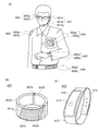
本発明の一態様は、上記記載の蓄電装置と、ディスプレイと、操作ボタンと、を有する電子機器である。 One embodiment of the present invention is an electronic device including the above-described power storage device, a display, and an operation button.
本発明の一態様により、体積あたりの容量が高い蓄電装置を提供することができる。また、本発明の一態様により、可撓性を有する新規な構造の蓄電装置を提供することができる。また、本発明の一態様により、繰り返し曲げることのできる蓄電装置を提供することができる。また、本発明の一態様により、信頼性の高い蓄電装置を提供することができる。また、本発明の一態様により、寿命の長い蓄電装置を提供することができる。 According to one embodiment of the present invention, a power storage device with high capacity per volume can be provided. Further, according to one embodiment of the present invention, a power storage device having a novel structure with flexibility can be provided. According to one embodiment of the present invention, a power storage device that can be bent repeatedly can be provided. According to one embodiment of the present invention, a highly reliable power storage device can be provided. According to one embodiment of the present invention, a power storage device with a long lifetime can be provided.
なお、これらの効果の記載は、他の効果の存在を妨げるものではない。なお、本発明の一態様は、必ずしも、これらの効果の全てを有する必要はない。なお、これら以外の効果は、明細書、図面、請求項などの記載から、自ずと明らかとなるものであり、明細書、図面、請求項などの記載から、これら以外の効果を抽出することが可能である。 Note that the description of these effects does not disturb the existence of other effects. Note that one embodiment of the present invention does not necessarily have all of these effects. It should be noted that the effects other than these are naturally obvious from the description of the specification, drawings, claims, etc., and it is possible to extract the other effects from the descriptions of the specification, drawings, claims, etc. It is.
以下では、本発明の実施の形態について図面を用いて詳細に説明する。ただし、本発明は以下の説明に限定されず、その形態および詳細を様々に変更し得ることは、当業者であれば容易に理解される。また、本発明は以下に示す実施の形態の記載内容に限定して解釈されるものではない。 Hereinafter, embodiments of the present invention will be described in detail with reference to the drawings. However, the present invention is not limited to the following description, and it will be easily understood by those skilled in the art that modes and details can be variously changed. In addition, the present invention is not construed as being limited to the description of the embodiments below.
図面等において示す各構成の、位置、大きさ、範囲などは、理解を容易にするため、実際の位置、大きさ、範囲などを表していない場合がある。このため、開示する発明は、必ずしも、図面等に開示された位置、大きさ、範囲などに限定されない。 The position, size, range, and the like of each component illustrated in the drawings and the like may not represent the actual position, size, range, or the like for easy understanding. Therefore, the disclosed invention is not necessarily limited to the position, size, range, or the like disclosed in the drawings and the like.
「電気的に接続」には、「何らかの電気的作用を有するもの」を介して接続されている場合が含まれる。ここで、「何らかの電気的作用を有するもの」は、接続対象間での電気信号の授受を可能とするものであれば、特に制限はない。 “Electrically connected” includes a case of being connected via “something having an electric action”. Here, the “having some electric action” is not particularly limited as long as it can exchange electric signals between the connection targets.
なお、「膜」という言葉と、「層」という言葉とは、場合によっては、または、状況に応じて、互いに入れ替えることが可能である。例えば、「導電層」という用語を、「導電膜」という用語に変更することが可能な場合がある。または、例えば、「絶縁膜」という用語を、「絶縁層」という用語に変更することが可能な場合がある。 Note that the terms “film” and “layer” can be interchanged with each other depending on the case or circumstances. For example, the term “conductive layer” may be changed to the term “conductive film”. Alternatively, for example, the term “insulating film” may be changed to the term “insulating layer” in some cases.
また、本明細書等で説明する本発明の構成において、同一部分又は同様の機能を有する部分には同一の符号を異なる図面間で共通して用い、その繰り返しの説明は省略する。 In the structures of the present invention described in this specification and the like, the same portions or portions having similar functions are denoted by the same reference numerals in different drawings, and description thereof is not repeated.
また、本明細書等において、第1、第2、第3などとして付される序数詞は、便宜上用いるものであって工程の順番や上下の位置関係などを示すものではない。そのため、例えば、「第1の」を「第2の」又は「第3の」などと適宜置き換えて説明することができる。また、本明細書等に記載されている序数詞と、本発明の一態様を特定するために用いられる序数詞は一致しない場合がある。 In this specification and the like, the ordinal numbers attached as the first, second, third, etc. are used for the sake of convenience and do not indicate the order of steps or the positional relationship between the upper and lower sides. Therefore, for example, the description can be made by appropriately replacing “first” with “second” or “third”. In addition, the ordinal numbers described in this specification and the like may not match the ordinal numbers used to specify one embodiment of the present invention.
また、本明細書において可撓性とは、物体が柔軟であり、曲がることが可能である性質を指す。物体にかかる外力に応じて物体が変形することができる性質であり、弾性や変形前の形状への復元性の有無を問題にはしない。可撓性を有する蓄電装置は、外力に応じて変形することができる。可撓性を有する蓄電装置は、変形した状態で固定して使用することもでき、繰り返し変形させて使用してもよく、変形していない状態で使用することもできる。また、本明細書等において、外装体の内部とは、蓄電装置において外装体で囲われた(または包まれた)領域を指し、正極、負極、活物質層、セパレータ等の構造物および電解液等が存在する領域である。 In this specification, the term “flexibility” refers to the property that an object is soft and can be bent. The property is that the object can be deformed according to the external force applied to the object, and it does not matter whether there is elasticity or the ability to restore the shape before deformation. A power storage device having flexibility can be deformed in accordance with an external force. The flexible power storage device can be fixed and used in a deformed state, can be repeatedly deformed, or can be used in an undeformed state. In this specification and the like, the inside of an exterior body refers to a region surrounded (or wrapped) by the exterior body in a power storage device, and structures such as a positive electrode, a negative electrode, an active material layer, and a separator, and an electrolyte solution Etc. exist in the region.
また、本明細書などにおいて、蓄電装置は蓄電池などと置き換えて用いてもよい。 In this specification and the like, a power storage device may be used instead of a storage battery.
また、本発明を実施するための形態に記載の内容は、適宜組み合わせて用いることができる。 Further, the contents described in the embodiments for carrying out the present invention can be used in appropriate combination.
(実施の形態1)
本実施の形態では、本発明の一態様に係る蓄電装置110と、その作製方法について説明する。
(Embodiment 1)
In this embodiment, the
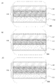
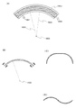
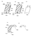
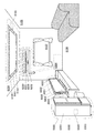
図1は、蓄電装置110を示した図である。図1(A)に示す蓄電装置110は、外装体116に包まれた内部構造物117を有している。内部構造物117は、電極とセパレータとを有しており、電極はリード電極115と電気的に接続されている。
FIG. 1 is a diagram illustrating the
図1(B)は、蓄電装置110を、図1(A)のA1−A2で切断した断面図を示す。また、図1(C)に、外装体116の拡大図を示す。
FIG. 1B is a cross-sectional view of the
図1(B)に示すように、蓄電装置110は、外装体116に、内部構造物117および電解液107が包まれた構成となっている。また、内部構造物117は、第1の積層体100a、第2の積層体100b、第3の積層体100cおよび第4の積層体100dを有する。なお、本実施の形態における蓄電装置110が有する積層体の数は主に4であるが、これに限定されない。
As shown in FIG. 1B, the
また図1(C)に示すように、外装体116は、フィルム112と、フィルム113と、フィルム112およびフィルム113の間に設けられたフィルム111と、を有する。
As illustrated in FIG. 1C, the
フィルム111は、チタンと、ニオブ、タンタル、バナジウム、ジルコニウムまたはハフニウムから選ばれた一以上の元素と、を有する。また、さらにモリブデン、クロムまたはアルミニウムから選ばれた一以上の元素を有すると好ましい。このように、フィルム111は、チタンと、上記元素と、を有することによって、低ヤング率、高強度のフィルムを形成することができる。そのため、繰り返し曲げによる変形によって、外装体が破断するのを抑制することができる。
The
また、本実施の形態に示すように、チタンを有するフィルム111を蓄電装置の外装体に用いることで、例えば蓄電装置が直接人体に触れるような箇所に設けた場合においても、他の金属を有するフィルムを外装体に用いた場合と比べ、金属アレルギー反応を抑制することができるため好ましい。また同様に、体内などに蓄電装置を設ける場合においても好ましい。
In addition, as shown in this embodiment mode, the
また、フィルム111は、10μm以上150μm以下の厚さである領域を有する。それにより、フィルム111は可撓性を有することができる。
The
また、フィルム111は、密度が5g/cm3以上6g/cm3以下である領域を有する。それによって、外部からの水分や酸素などのガスを遮断でき、さらに繰り返し曲げなどの変形による破断を防ぐことができる。
In addition, the
フィルム111は、チタンと、ニオブ、タンタル、バナジウム、ジルコニウムまたはハフニウムから選ばれた一以上の元素との合金によって形成することができる。例えばTi−Nb−Ta−Zr−OまたはTi−Ta−Nb−V−Zr−Oなどを用いればよい。それにより、フィルム111は、0.2%耐力を有することができる。例えば、900MPa以上1700MPa以下の0.2%耐力を有する。なお0.2%耐力とは、応力を加えた後に除荷し、そのときの永久ひずみが0.2%になるような応力のことをいう。
The
また、フィルム111は、延性または展性を有し、曲げなどの変形時においても、フィルム111が破断しにくく、ガスバリア性を保持することができる。
Further, the
フィルム112およびフィルム113は、有機材料を有すると好ましい。それにより、フィルム111は可撓性を有することができる。
The
上記フィルムを用いた外装体とすることによって、可撓性を有する蓄電装置を作製することができる。 A flexible power storage device can be manufactured by using the exterior body including the film.
また、外装体116は、フィルム112またはフィルム113を設けない構成としてもよい。例えば、図2(A)に示すように、フィルム112を設けない構成の外装体116としてもよい。また、図2(B)に示すように、フィルム113を設けない構成の外装体116としてもよい。また、図2(C)に示すように、フィルム112およびフィルム113を設けない構成の外装体116としてもよい。
Further, the
また、フィルム111、フィルム112およびフィルム113は、それぞれ単層で形成されてもよく、2層以上の積層で形成されてもよい。
Moreover, the
フィルム111の密度は、例えばラザフォード後方散乱法(RBS:Rutherford Backscattering Spectrometry)やX線反射率測定法(XRR:X−Ray Reflection)を用いて測定すればよい。
The density of the
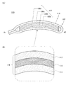
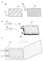
また図3に示すように、アルミニウム、ステンレス、銅およびニッケル等の可撓性に優れた薄膜200を設ける構成としてもよい。また、薄膜200は、グラフェン化合物を有していてもよい。
Moreover, as shown in FIG. 3, it is good also as a structure which provides the
本明細書などにおいて、グラフェンを基本骨格として有する化合物を「グラフェン化合物(「グラフェンコンパウンド:Graphene Compound」ともいう)」と呼ぶ。なお、グラフェンは、炭素原子が1原子層配列したものであり、炭素原子間にπ結合を有する。また、グラフェンは、グラフェン化合物の一種である。 In this specification and the like, a compound having graphene as a basic skeleton is referred to as a “graphene compound (also referred to as“ graphene compound ”)”. Note that graphene has a single atomic layer arrangement of carbon atoms and has a π bond between the carbon atoms. Graphene is a kind of graphene compound.
以下に、グラフェン化合物について詳細を説明する。 Details of the graphene compound will be described below.
グラフェン化合物のうち、グラフェンが2層以上100層以下重なったものを、マルチグラフェンと呼ぶ場合がある。グラフェンおよびマルチグラフェンは、例えば、長手方向の長さが50nm以上100μm以下または800nm以上50μm以下である。 Among graphene compounds, a graphene compound in which two or more layers and 100 layers or less are overlapped may be referred to as multi-graphene. Graphene and multi-graphene have, for example, a length in the longitudinal direction of 50 nm to 100 μm or 800 nm to 50 μm.
グラフェン化合物は例えば、グラフェンまたはマルチグラフェンに、炭素以外の原子、または炭素以外の原子を有する原子団が修飾された化合物であってもよい。また、グラフェンまたはマルチグラフェンに、アルキル基等の炭素を主とした原子団が修飾された化合物であってもよい。なお、グラフェンまたはマルチグラフェンを修飾する原子および原子団を、置換基、官能基、または特性基等と呼ぶ場合がある。ここで、グラフェン化合物は、上述の原子または原子団が修飾されたグラフェンも含む。 For example, the graphene compound may be a compound in which an atom other than carbon or an atomic group having an atom other than carbon is modified in graphene or multi-graphene. Further, a compound in which an atomic group mainly containing carbon such as an alkyl group is modified on graphene or multi-graphene may be used. Note that atoms and atomic groups that modify graphene or multi-graphene may be referred to as substituents, functional groups, or characteristic groups. Here, the graphene compound also includes graphene in which the above-described atoms or atomic groups are modified.
ここで、グラフェン化合物の表面と裏面に、それぞれ異なる原子や原子団を修飾してもよい。また、グラフェン化合物がマルチグラフェン、複数のグラフェン、複数のマルチグラフェン等を有する場合に、それぞれの層に異なる原子や原子団を修飾してもよい。 Here, different atoms and atomic groups may be modified on the front and back surfaces of the graphene compound. In the case where the graphene compound includes multi-graphene, a plurality of graphenes, a plurality of multi-graphenes, or the like, different atoms or atomic groups may be modified in each layer.
上述の原子団が修飾されたグラフェンの一例として、酸素を含む置換基、官能基もしくは特性基、または酸素が修飾されたグラフェンまたはマルチグラフェンを用いてもよい。ここで酸素を含む官能基として例えば、エポキシ基、カルボキシル基などのカルボニル基、または水酸基等が挙げられる。酸素または酸素を含む原子団が修飾されたグラフェンを酸化グラフェンと呼ぶ場合がある。 As an example of the above-described modified atomic group, oxygen-containing substituents, functional groups, or characteristic groups, or oxygen-modified graphene or multi-graphene may be used. Examples of the functional group containing oxygen include a carbonyl group such as an epoxy group and a carboxyl group, or a hydroxyl group. Graphene in which oxygen or an oxygen-containing atomic group is modified may be referred to as graphene oxide.
グラフェン化合物は、複数のグラフェン化合物が部分的に重なりながら1枚のシート状となっていてもよい。このようなグラフェン化合物を、グラフェン化合物シートと呼ぶ場合がある。グラフェン化合物シートは例えば、厚さが0.33nm以上50μm以下、より好ましくは0.34nmより大きく10μm以下の領域を有する。グラフェン化合物シートに、炭素以外の原子、炭素以外の原子を有する原子団、またはアルキル基等の炭素を主とした原子団等が修飾されてもよい。また、グラフェン化合物シートが有する複数の層のそれぞれにおいて、異なる原子または原子団が修飾されていてもよい。 The graphene compound may be in the form of one sheet while a plurality of graphene compounds partially overlap. Such a graphene compound may be referred to as a graphene compound sheet. The graphene compound sheet has, for example, a region having a thickness of 0.33 nm to 50 μm, more preferably greater than 0.34 nm to 10 μm. The graphene compound sheet may be modified with atoms other than carbon, atomic groups having atoms other than carbon, or atomic groups mainly composed of carbon such as alkyl groups. Further, different atoms or atomic groups may be modified in each of the plurality of layers of the graphene compound sheet.
グラフェン化合物は、炭素で構成される六員環の他に、炭素で構成される五員環や、炭素で構成される七員環以上の多員環を有してもよい。ここで、六員環以外の多員環の近傍では、リチウムイオンが通過可能な領域が生じる場合がある。 In addition to the six-membered ring composed of carbon, the graphene compound may have a five-membered ring composed of carbon or a multi-membered ring composed of seven or more members composed of carbon. Here, in the vicinity of a multi-membered ring other than the six-membered ring, a region where lithium ions can pass may occur.
図3(A)は、フィルム111を、薄膜200で挟んでいる構成を示す。図3(B)は、薄膜200を、フィルム111で挟んでいる構成を示す。また、図3(C)に示すように、図3(A)および図3(B)を組み合わせたような構成としてもよい。さらに、薄膜200およびフィルム111の積層数を増加させた構成としてもよい。
FIG. 3A shows a structure in which the
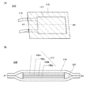
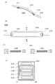
また、図4(A)に図1(A)のA1−A2で切断した断面図を示し、図4(B)に内部構造物117端部の拡大図を示す。図4(B)に示すように、内部構造物117における各積層体は、それぞれ負極集電体101、負極活物質層102、セパレータ103、正極活物質層104および正極集電体105を有する。
4A is a cross-sectional view taken along A1-A2 in FIG. 1A, and FIG. 4B is an enlarged view of an end portion of the
また、蓄電装置110において、図4(B)の拡大図に示す通り、第1の積層体100a乃至第4の積層体100dは、それぞれ同様の層が積層された構造ではあるが、各積層体は、構成する層の積層順が互い違いに逆の関係となっている。また、各積層体は互いに同一の層が積層された構造に限定されない。
In the
蓄電装置110において、第1の積層体100aの正極集電体の正極活物質層が形成されていない面と、第2の積層体100bの正極集電体の正極活物質層が形成されていない面と、が接しており、第2の積層体100bの負極集電体の負極活物質層が形成されていない面と、第3の積層体100cの負極集電体の負極活物質層が形成されていない面と、が接しており、第3の積層体100cの正極集電体の正極活物質層が形成されていない面と、第4の積層体100dの正極集電体の正極活物質層が形成されていない面と、が接している。ただし、本発明の一態様に係る蓄電装置110において、すべての積層体が、互いの集電体同士で接していることに限定されない。また、正極および負極における集電体の両面に、活物質層を有する構造でもよい。
In the
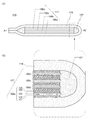
本発明の一態様に係る蓄電装置110は可撓性を有し、さまざまな形状に変形することができる。例えば図5(A)に示すように、蓄電装置110を曲げることができる。またその際、図5(B)に示す外装体116の拡大図のように、フィルム111、フィルム112およびフィルム113それぞれが可撓性を有している。
The
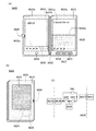
また、図6(A)に示す蓄電装置110において、外装体116同士が接している、二点鎖線で囲った部分の拡大図を、図6(B)および図6(C)に示す。
FIGS. 6B and 6C are enlarged views of a portion surrounded by a two-dot chain line in the
図6(B)に示すように、外装体116において、全体にフィルム111を有する構成としてもよい。また、図6(C)に示すように、外装体116において、一部、フィルム111が設けられていない構成としてもよい。
As shown in FIG. 6B, the
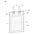
図7に、図1とは異なる外装体116の構成を有する蓄電装置210を示す。図7(A)に示す蓄電装置210において、A1−A2で切断した断面図を図7(B)に示す。蓄電装置210に用いる外装体116は、2枚の外装体116を重ねた構成となっている点が、図1に示す蓄電装置110と異なる。
FIG. 7 illustrates a
次に、本発明の一態様に係る蓄電装置について説明する。 Next, a power storage device according to one embodiment of the present invention is described.
<正極の構成>
まず、正極について説明する。正極は、図4(B)に示すように、正極活物質層104と、正極集電体105と、を有する。
<Configuration of positive electrode>
First, the positive electrode will be described. The positive electrode includes a positive electrode
正極活物質層104に用いられる正極活物質材料としては、リチウムイオン等のキャリアイオンの移動が可能な材料を用いることができる。例えば、オリビン型の結晶構造、層状岩塩型の結晶構造、又はスピネル型の結晶構造を有するリチウム含有材料等が挙げられる。
As the positive electrode active material used for the positive electrode
オリビン型構造のリチウム含有材料(一般式LiMPO4(Mは、Fe(II)、Mn(II)、Co(II)またはNi(II)))の代表例としては、LiFePO4、LiNiPO4、LiCoPO4、LiMnPO4、LiFeaNibPO4、LiFeaCobPO4、LiFeaMnbPO4、LiNiaCobPO4、LiNiaMnbPO4(a+b≦1、0<a<1、0<b<1)、LiFecNidCoePO4、LiFecNidMnePO4、LiNicCodMnePO4(c+d+e≦1、0<c<1、0<d<1、0<e<1)、LiFefNigCohMniPO4(f+g+h+i≦1、0<f<1、0<g<1、0<h<1、0<i<1)等がある。 Typical examples of olivine type lithium-containing materials (general formula LiMPO 4 (M is Fe (II), Mn (II), Co (II) or Ni (II))) include LiFePO 4 , LiNiPO 4 , LiCoPO 4 . 4 , LiMnPO 4 , LiFe a Ni b PO 4 , LiFe a Co b PO 4 , LiFe a Mn b PO 4 , LiNi a Co b PO 4 , LiNi a Mn b PO 4 (a + b ≦ 1, 0 <a <1, 0 <b <1), LiFe c Ni d Co e PO 4, LiFe c Ni d Mn e PO 4, LiNi c Co d Mn e PO 4 (c + d + e ≦ 1,0 <c <1,0 <d <1, 0 <e <1), LiFe f Ni g Co h Mn i PO 4 (f + g + h + i ≦ 1,0 <f <1,0 <g <1,0 <h <1,0 <i <1) Hitoshigaa .
例えば、リン酸鉄リチウム(LiFePO4)は、安全性、安定性、高容量密度、高電位、初期酸化(充電)時に引き抜けるリチウムイオンの存在等、正極活物質に求められる事項をバランスよく満たしているため、好ましい。 For example, lithium iron phosphate (LiFePO 4 ) satisfies the requirements for a positive electrode active material in a well-balanced manner, such as safety, stability, high capacity density, high potential, and the presence of lithium ions extracted during initial oxidation (charging). Therefore, it is preferable.
層状岩塩型の結晶構造を有するリチウム含有材料としては、例えば、コバルト酸リチウム(LiCoO2)、LiNiO2、LiMnO2、Li2MnO3、LiNi0.8Co0.2O2等のNiCo系(一般式は、LiNixCo1−xO2(0<x<1))、LiNi0.5Mn0.5O2等のNiMn系(一般式は、LiNixMn1−xO2(0<x<1))、LiNi1/3Mn1/3Co1/3O2等のNiMnCo系(NMCともいう。一般式は、LiNixMnyCo1−x−yO2(x>0、y>0、x+y<1))が挙げられる。さらに、Li(Ni0.8Co0.15Al0.05)O2、Li2MnO3−LiMO2(MはCo、NiまたはMn)等も挙げられる。 Examples of the lithium-containing material having a layered rock salt type crystal structure include NiCo-based materials such as lithium cobaltate (LiCoO 2 ), LiNiO 2 , LiMnO 2 , Li 2 MnO 3 , and LiNi 0.8 Co 0.2 O 2 ( The general formula is NiMn series such as LiNi x Co 1-x O 2 (0 <x <1)), LiNi 0.5 Mn 0.5 O 2 (general formula is LiNi x Mn 1-x O 2 (0 <x <1)), also referred to as NiMnCo system (NMC such LiNi 1/3 Mn 1/3 Co 1/3 O 2 . general formula, LiNi x Mn y Co 1- x-y O 2 (x> 0 , Y> 0, x + y <1)). Moreover, Li (Ni 0.8 Co 0.15 Al 0.05) O 2, Li 2 MnO 3 -LiMO 2 (M is Co, Ni or Mn) may also be mentioned, and the like.
特に、LiCoO2は、容量が大きいこと、LiNiO2に比べて大気中で安定であること、LiNiO2に比べて熱的に安定であること等の利点があるため、好ましい。 Particularly, LiCoO 2 has the capacity is large, it is stable in the atmosphere as compared to LiNiO 2, because there are advantages such that it is thermally stable than LiNiO 2, preferred.
スピネル型の結晶構造を有するリチウム含有材料としては、例えば、LiMn2O4、Li1+xMn2−xO4(0<x<2)、LiMn2−xAlxO4(0<x<2)、LiMn1.5Ni0.5O4等が挙げられる。 Examples of the lithium-containing material having a spinel crystal structure include LiMn 2 O 4 , Li 1 + x Mn 2−x O 4 (0 <x <2), LiMn 2−x Al x O 4 (0 <x <2 ), LiMn 1.5 Ni 0.5 O 4 and the like.
LiMn2O4等のマンガンを含むスピネル型の結晶構造を有するリチウム含有材料に、少量のニッケル酸リチウム(LiNiO2やLiNi1−xMxO2(0<x<1)(MはCo、Al等))を混合すると、マンガンの溶出を抑制する、電解液の分解を抑制する等の利点があり好ましい。 A small amount of lithium nickelate (LiNiO 2 or LiNi 1-x M x O 2 (0 <x <1) (M is Co), and a lithium-containing material having a spinel-type crystal structure containing manganese such as LiMn 2 O 4 . Mixing Al or the like) is preferable because of advantages such as suppression of manganese elution and suppression of electrolyte decomposition.
また、正極活物質として、一般式Li(2−j)MSiO4(Mは、Fe(II)、Mn(II)、Co(II)、またはNi(II))(0≦j≦2)で表される複合酸化物を用いることができる。一般式Li(2−j)MSiO4の代表例としては、Li(2−j)FeSiO4、Li(2−j)NiSiO4、Li(2−j)CoSiO4、Li(2−j)MnSiO4、Li(2−j)FekNilSiO4、Li(2−j)FekColSiO4、Li(2−j)FekMnlSiO4、Li(2−j)NikColSiO4、Li(2−j)NikMnlSiO4(k+l≦1、0<k<1、0<l<1)、Li(2−j)FemNinCoqSiO4、Li(2−j)FemNinMnqSiO4、Li(2−j)NimConMnqSiO4(m+n+q≦1、0<m<1、0<n<1、0<q<1)、Li(2−j)FerNisCotMnuSiO4(r+s+t+u≦1、0<r<1、0<s<1、0<t<1、0<u<1)等が挙げられる。 In addition, as a positive electrode active material, a general formula Li (2-j) MSiO 4 (M is Fe (II), Mn (II), Co (II), or Ni (II)) (0 ≦ j ≦ 2) The composite oxide represented can be used. Representative examples of the general formula Li (2-j) MSiO 4 include Li (2-j) FeSiO 4 , Li (2-j) NiSiO 4 , Li (2-j) CoSiO 4 , Li (2-j) MnSiO 4, Li (2-j) Fe k Ni l SiO 4, Li (2-j) Fe k Co l SiO 4, Li (2-j) Fe k Mn l SiO 4, Li (2-j) Ni k Co l SiO 4, Li (2- j) Ni k Mn l SiO 4 (k + l ≦ 1,0 <k <1,0 <l <1), Li (2-j) Fe m Ni n Co q SiO 4, Li (2-j) Fe m Ni n Mn q SiO 4, Li (2-j) Ni m Co n Mn q SiO 4 (m + n + q ≦ 1,0 <m <1,0 <n <1,0 <q <1 ), Li (2-j) Fe r Ni s Co t Mn u Si 4 (r + s + t + u ≦ 1,0 <r <1,0 <s <1,0 <t <1,0 <u <1) , and the like.
また、正極活物質として、AxM2(XO4)3(AはLi、NaまたはMg)(MはFe、Mn、Ti、V、NbまたはAl)(XはS、P、Mo、W、AsまたはSi)の一般式で表されるナシコン型化合物を用いることができる。ナシコン型化合物としては、Fe2(MnO4)3、Fe2(SO4)3、Li3Fe2(PO4)3等が挙げられる。また、正極活物質として、Li2MPO4F、Li2MP2O7、Li5MO4(MはFeまたはMn)の一般式で表される化合物、NaFeF3、FeF3等のペロブスカイト型フッ化物、TiS2、MoS2等の金属カルコゲナイド(硫化物、セレン化物、テルル化物)、LiMVO4等の逆スピネル型の結晶構造を有するリチウム含有材料、バナジウム酸化物系(V2O5、V6O13、LiV3O8等)、マンガン酸化物、有機硫黄等の材料を用いることができる。 Further, as a positive electrode active material, A x M 2 (XO 4 ) 3 (A is Li, Na or Mg) (M is Fe, Mn, Ti, V, Nb or Al) (X is S, P, Mo, W) , As or Si), a NASICON compound represented by the general formula can be used. Examples of NASICON compounds include Fe 2 (MnO 4 ) 3 , Fe 2 (SO 4 ) 3 , and Li 3 Fe 2 (PO 4 ) 3 . Further, as a positive electrode active material, a compound represented by a general formula of Li 2 MPO 4 F, Li 2 MP 2 O 7 , Li 5 MO 4 (M is Fe or Mn), a perovskite type fluoride such as NaFeF 3 , FeF 3, etc. Metal, chalcogenides such as TiS 2 and MoS 2 (sulfides, selenides, tellurides), lithium-containing materials having an inverse spinel crystal structure such as LiMVO 4 , vanadium oxides (V 2 O 5 , V 6 O 13 , LiV 3 O 8 or the like), manganese oxide, organic sulfur, or the like can be used.
なお、キャリアイオンが、リチウムイオン以外のアルカリ金属イオンや、アルカリ土類金属イオンの場合、正極活物質として、上記化合物や酸化物において、リチウムの代わりに、アルカリ金属(例えば、ナトリウムやカリウム等)、アルカリ土類金属(例えば、カルシウム、ストロンチウム、バリウム、ベリリウム、マグネシウム等)を用いてもよい。例えば、NaFeO2や、Na2/3[Fe1/2Mn1/2]O2などのナトリウム含有層状酸化物を正極活物質として用いることができる。 In addition, when carrier ions are alkali metal ions other than lithium ions or alkaline earth metal ions, as the positive electrode active material, an alkali metal (for example, sodium or potassium) is used instead of lithium in the above compound or oxide. Alkaline earth metals (eg, calcium, strontium, barium, beryllium, magnesium, etc.) may be used. For example, a sodium-containing layered oxide such as NaFeO 2 or Na 2/3 [Fe 1/2 Mn 1/2 ] O 2 can be used as the positive electrode active material.
また、正極活物質として、上記材料を複数組み合わせた材料を用いてもよい。例えば、上記材料を複数組み合わせた固溶体を正極活物質として用いることができる。例えば、LiCo1/3Mn1/3Ni1/3O2とLi2MnO3の固溶体を正極活物質として用いることができる。 A material obtained by combining a plurality of the above materials may be used as the positive electrode active material. For example, a solid solution obtained by combining a plurality of the above materials can be used as the positive electrode active material. For example, a solid solution of LiCo 1/3 Mn 1/3 Ni 1/3 O 2 and Li 2 MnO 3 can be used as the positive electrode active material.
正極活物質は、一次粒子の平均粒径が50nm以上100μm以下のものを用いるとよい。 As the positive electrode active material, a material having an average primary particle diameter of 50 nm or more and 100 μm or less is preferably used.
正極活物質は、負極活物質と共に、蓄電装置の電池反応の中心的役割を担い、キャリアイオンの放出および吸収を行う物質である。蓄電装置の寿命を高めるためには、電池反応の不可逆反応に係る容量が少ない材料であることが好ましく、充放電効率の高い材料であることが好ましい。 The positive electrode active material, together with the negative electrode active material, plays a central role in the battery reaction of the power storage device, and is a substance that releases and absorbs carrier ions. In order to increase the life of the power storage device, it is preferable to use a material with a small capacity related to the irreversible reaction of the battery reaction, and it is preferable to use a material with high charge / discharge efficiency.
活物質は電解液と接するため、活物質と電解液とが反応し、反応により活物質が失われ劣化すると、蓄電装置の容量が低下する。そのため、劣化の少ない蓄電装置を実現するためには、蓄電装置内において上記反応が生じないことが望ましい。 Since the active material is in contact with the electrolytic solution, the active material reacts with the electrolytic solution, and when the active material is lost and deteriorated due to the reaction, the capacity of the power storage device decreases. Therefore, in order to realize a power storage device with little deterioration, it is desirable that the above reaction does not occur in the power storage device.
電極の導電助剤として、アセチレンブラック(AB)、グラファイト(黒鉛)粒子、カーボンナノチューブ、グラフェン、酸化グラフェン、フラーレンなどを用いることができる。 As the conductive aid for the electrode, acetylene black (AB), graphite (graphite) particles, carbon nanotubes, graphene, graphene oxide, fullerene, or the like can be used.
導電助剤により、電極中に電気伝導のネットワークを形成することができる。導電助剤により、正極活物質どうしの電気伝導の経路を維持することができる。正極活物質層中に導電助剤を添加することにより、高い電気伝導性を有する正極活物質層104を実現することができる。
The conductive assistant can form an electrically conductive network in the electrode. The conductive auxiliary agent can maintain the electric conduction path between the positive electrode active materials. By adding a conductive additive in the positive electrode active material layer, the positive electrode
また、バインダーとして、代表的なポリフッ化ビニリデン(PVDF)の他、ポリイミド、ポリテトラフルオロエチレン、ポリビニルクロライド、エチレンプロピレンジエンポリマー、フッ素ゴム、ポリメチルメタクリレート、ポリエチレン、ニトロセルロース等を用いることができる。 In addition to typical polyvinylidene fluoride (PVDF), polyimide, polytetrafluoroethylene, polyvinyl chloride, ethylene propylene diene polymer, fluororubber, polymethyl methacrylate, polyethylene, nitrocellulose, and the like can be used as the binder.
正極活物質層104の総量に対するバインダーの含有量は、1wt%以上10wt%以下が好ましく、2wt%以上8wt%以下がより好ましく、3wt%以上5wt%以下がさらに好ましい。また、正極活物質層104の総量に対する導電助剤の含有量は、1wt%以上10wt%以下が好ましく、1wt%以上5wt%以下がより好ましい。
The content of the binder with respect to the total amount of the positive electrode
塗布法を用いて正極活物質層104を形成する場合は、正極活物質とバインダーと導電助剤と分散媒を混合して電極スラリーを作製し、正極集電体105上に塗布して乾燥させればよい。
When the positive electrode
なお、正極集電体105にはステンレス、金、白金、アルミニウム、チタン等の金属、及びこれらの合金など、導電性の高く、リチウム等のキャリアイオンと合金化しない材料を用いることができる。また、シリコン、チタン、ネオジム、スカンジウム、モリブデンなどの耐熱性を向上させる元素が添加されたアルミニウム合金を用いることができる。また、シリコンと反応してシリサイドを形成する金属元素で形成してもよい。シリコンと反応してシリサイドを形成する金属元素としては、ジルコニウム、チタン、ハフニウム、バナジウム、ニオブ、タンタル、クロム、モリブデン、タングステン、コバルト、ニッケル等がある。正極集電体は、箔状、板状(シート状)、網状、パンチングメタル状、エキスパンドメタル状等の形状を適宜用いることができる。正極集電体105は、厚みが5μm以上30μm以下のものを用いるとよい。また、電極集電体の表面の一部に、グラファイト、グラフェン、酸化グラフェンなどを用いてアンダーコート層を設けてもよい。
Note that the positive electrode
なお、正極集電体105の片面に正極活物質層104を設け、もう一方の面に正極活物質層を設けない構成とすることができる。その場合、正極活物質層が設けられていない面において、正極集電体105の表面は平坦で摩擦係数が小さい。そのため、該表面に、他の正極集電体の正極活物質層が設けられていない面が接するとき、応力に応じて両集電体は互いに摺動することができる。
Note that a structure in which the positive electrode
以上のようにして、蓄電装置の正極を作製することができる。 As described above, the positive electrode of the power storage device can be manufactured.
<負極の構成>
次に負極について説明する。負極は、図4(B)に示すように、負極活物質層102と、負極集電体101と、を有する。負極を形成する工程を以下に説明する。
<Configuration of negative electrode>
Next, the negative electrode will be described. The negative electrode includes a negative electrode
負極活物質層102に用いられる負極活物質として、炭素系材料としては、黒鉛、易黒鉛化性炭素(ソフトカーボン)、難黒鉛化性炭素(ハードカーボン)、カーボンナノチューブ、グラフェン、カーボンブラック等がある。黒鉛としては、メソカーボンマイクロビーズ(MCMB)、コークス系人造黒鉛、ピッチ系人造黒鉛等の人造黒鉛や、球状化天然黒鉛等の天然黒鉛がある。また、黒鉛の形状としては鱗片状のものや球状のものなどがある。
Examples of the negative electrode active material used for the negative electrode
負極活物質として、炭素系材料以外に、リチウムとの合金化・脱合金化反応により充放電反応を行うことが可能な材料も用いることができる。例えば、Ga、Si、Al、Ge、Sn、Pb、Sb、Bi、Ag、Zn、Cd、In等のうち少なくとも一つを含む材料を用いることができる。このような元素は炭素と比べて容量が大きく、特にシリコンは理論容量が4200mAh/gと高く好ましい。このような元素を用いた合金系材料としては、例えば、Mg2Si、Mg2Ge、Mg2Sn、SnS2、V2Sn3、FeSn2、CoSn2、Ni3Sn2、Cu6Sn5、Ag3Sn、Ag3Sb、Ni2MnSb、CeSb3、LaSn3、La3Co2Sn7、CoSb3、InSb、SbSn等がある。 In addition to the carbon-based material, a material capable of performing a charge / discharge reaction by an alloying / dealloying reaction with lithium can be used as the negative electrode active material. For example, a material containing at least one of Ga, Si, Al, Ge, Sn, Pb, Sb, Bi, Ag, Zn, Cd, In, and the like can be used. Such an element has a larger capacity than carbon, and silicon is particularly preferable because its theoretical capacity is as high as 4200 mAh / g. Examples of alloy materials using such elements include Mg 2 Si, Mg 2 Ge, Mg 2 Sn, SnS 2 , V 2 Sn 3 , FeSn 2 , CoSn 2 , Ni 3 Sn 2 , and Cu 6 Sn 5. , Ag 3 Sn, Ag 3 Sb, Ni 2 MnSb, CeSb 3 , LaSn 3 , La 3 Co 2 Sn 7 , CoSb 3 , InSb, SbSn, and the like.
また、負極活物質として、SiO、SnO、SnO2、二酸化チタン(TiO2)、リチウムチタン酸化物(Li4Ti5O12)、リチウム−黒鉛層間化合物(LixC6)、五酸化ニオブ(Nb2O5)、酸化タングステン(WO2)、酸化モリブデン(MoO2)等の酸化物を用いることができる。なお、SiOとは、ケイ素リッチの部分を含むケイ素酸化物の粉末を指しており、SiOy(2>y>0)とも表記できる。例えばSiOは、Si2O3、Si3O4、またはSi2Oから選ばれた単数または複数を含む材料や、Siの粉末と二酸化ケイ素SiO2の混合物も含む。また、SiOは他の元素(炭素、窒素、鉄、アルミニウム、銅、チタン、カルシウム、マンガンなど)を含む場合もある。即ち、単結晶Si、アモルファスSi、多結晶Si、Si2O3、Si3O4、Si2O、SiO2から選ばれる複数を含む材料を指しており、SiOは有色材料である。SiOではないSiOx(xは2以上)であれば無色透明、或いは白色であり、区別することができる。ただし、二次電池の材料としてSiOを用いて二次電池を作製した後、充放電を繰り返すなどによって、SiOが酸化した場合には、SiO2に変質する場合もある。 Further, as the negative electrode active material, SiO, SnO, SnO 2, titanium dioxide (TiO 2), lithium titanium oxide (Li 4 Ti 5 O 12) , lithium - graphite intercalation compound (Li x C 6), niobium pentoxide ( An oxide such as Nb 2 O 5 ), tungsten oxide (WO 2 ), or molybdenum oxide (MoO 2 ) can be used. Note that SiO refers to a silicon oxide powder containing a silicon-rich portion, and can also be expressed as SiO y (2>y> 0). For example, SiO includes a material including one or more selected from Si 2 O 3 , Si 3 O 4 , or Si 2 O, and a mixture of Si powder and silicon dioxide SiO 2 . In addition, SiO may contain other elements (carbon, nitrogen, iron, aluminum, copper, titanium, calcium, manganese, etc.). That is, it refers to a material containing a plurality of materials selected from single crystal Si, amorphous Si, polycrystalline Si, Si 2 O 3 , Si 3 O 4 , Si 2 O, and SiO 2 , and SiO is a colored material. If it is SiO x that is not SiO (x is 2 or more), it is colorless and transparent, or white, and can be distinguished. However, when a secondary battery is manufactured using SiO as a material of the secondary battery, and SiO is oxidized by repeating charge and discharge, it may be transformed into SiO 2 .
また、負極活物質として、リチウムと遷移金属の複窒化物である、Li3N型構造をもつLi3−xMxN(MはCo、NiまたはCu)を用いることができる。例えば、Li2.6Co0.4N3は大きな充放電容量(900mAh/g、1890mAh/cm3)を有するため好ましい。 Further, as the anode active material, a double nitride of lithium and a transition metal, Li 3-x M x N with Li 3 N type structure (M is Co, Ni or Cu) can be used. For example, Li 2.6 Co 0.4 N 3 is preferable because it has a large charge / discharge capacity (900 mAh / g, 1890 mAh / cm 3 ).
リチウムと遷移金属の複窒化物を用いると、負極活物質中にリチウムイオンを含むため、正極活物質としてリチウムイオンを含まないV2O5、Cr3O8等の材料と組み合わせることができる。なお、正極活物質にリチウムイオンを含む材料を用いる場合でも、あらかじめ正極活物質に含まれるリチウムイオンを脱離させることで、負極活物質としてリチウムと遷移金属の複窒化物を用いることができる。 When a lithium and transition metal double nitride is used, since the negative electrode active material contains lithium ions, it can be combined with a material such as V 2 O 5 or Cr 3 O 8 that does not contain lithium ions as the positive electrode active material. Note that even when a material containing lithium ions is used for the positive electrode active material, lithium and transition metal double nitride can be used as the negative electrode active material by previously desorbing lithium ions contained in the positive electrode active material.
また、コンバージョン反応が生じる材料を負極活物質として用いることもできる。例えば、酸化コバルト(CoO)、酸化ニッケル(NiO)、酸化鉄(FeO)等の、リチウムと合金化反応を行わない遷移金属酸化物を負極活物質に用いてもよい。コンバージョン反応が生じる材料としては、さらに、Fe2O3、CuO、Cu2O、RuO2、Cr2O3等の酸化物、CoS0.89、NiS、CuS等の硫化物、Zn3N2、Cu3N、Ge3N4等の窒化物、NiP2、FeP2、CoP3等のリン化物、FeF3、BiF3等のフッ化物でも起こる。 A material that causes a conversion reaction can also be used as the negative electrode active material. For example, a transition metal oxide that does not undergo an alloying reaction with lithium, such as cobalt oxide (CoO), nickel oxide (NiO), or iron oxide (FeO), may be used as the negative electrode active material. As a material causing the conversion reaction, oxides such as Fe 2 O 3 , CuO, Cu 2 O, RuO 2 and Cr 2 O 3 , sulfides such as CoS 0.89 , NiS and CuS, Zn 3 N 2 are further included. This also occurs in nitrides such as Cu 3 N and Ge 3 N 4 , phosphides such as NiP 2 , FeP 2 and CoP 3 , and fluorides such as FeF 3 and BiF 3 .
負極活物質は、例えば粒径が50nm以上100μm以下のものを用いるとよい。 As the negative electrode active material, for example, a material having a particle diameter of 50 nm to 100 μm is preferably used.
なお、正極活物質層104においても負極活物質層102においても、活物質材料は複数の材料を特定の割合で組み合わせて用いてもよい。活物質層に複数の材料を用いることで、より詳細に活物質層の性能を選択することができる。
Note that in both the positive electrode
電極の導電助剤として、アセチレンブラック(AB)、グラファイト(黒鉛)粒子、カーボンナノチューブ、グラフェン、酸化グラフェン、フラーレンなどを用いることができる。 As the conductive aid for the electrode, acetylene black (AB), graphite (graphite) particles, carbon nanotubes, graphene, graphene oxide, fullerene, or the like can be used.
導電助剤により、電極中に電気伝導のネットワークを形成することができる。導電助剤により、負極活物質どうしの電気伝導の経路を維持することができる。負極活物質層中に導電助剤を添加することにより、高い電気伝導性を有する負極活物質層102を実現することができる。
The conductive assistant can form an electrically conductive network in the electrode. The conductive auxiliary agent can maintain the electric conduction path between the negative electrode active materials. By adding a conductive additive in the negative electrode active material layer, the negative electrode
また、バインダーとして、代表的なポリフッ化ビニリデン(PVDF)の他、ポリイミド、ポリビニルクロライド、エチレンプロピレンジエンポリマー、スチレン−ブタジエンゴム、アクリロニトリル−ブタジエンゴム、フッ素ゴム、ポリ酢酸ビニル、ポリメチルメタクリレート、ポリエチレン、ニトロセルロース等を用いることができる。 In addition to typical polyvinylidene fluoride (PVDF), as a binder, polyimide, polyvinyl chloride, ethylene propylene diene polymer, styrene-butadiene rubber, acrylonitrile-butadiene rubber, fluorine rubber, polyvinyl acetate, polymethyl methacrylate, polyethylene, Nitrocellulose or the like can be used.
負極活物質層102の総量に対するバインダーの含有量は、1wt%以上10wt%以下が好ましく、2wt%以上8wt%以下がより好ましく、3wt%以上5wt%以下がさらに好ましい。また、負極活物質層102の総量に対する導電助剤の含有量は、1wt%以上10wt%以下が好ましく、1wt%以上5wt%以下がより好ましい。
The content of the binder with respect to the total amount of the negative electrode
塗布法を用いて負極活物質層102を形成する場合は、負極活物質とバインダーと導電助剤と分散媒を混合してスラリーを作製し、負極集電体101に塗布して乾燥させる。また、乾燥後に必要があればプレス処理を行ってもよい。
When the negative electrode
なお、負極集電体101には、ステンレス、金、白金、鉄、銅、チタン、タンタル等の金属、及びこれらの合金など、導電性の高く、リチウム等のキャリアイオンと合金化しない材料を用いることができる。また、シリコンと反応してシリサイドを形成する金属元素で形成してもよい。シリコンと反応してシリサイドを形成する金属元素としては、ジルコニウム、チタン、ハフニウム、バナジウム、ニオブ、タンタル、クロム、モリブデン、タングステン、コバルト、ニッケル等がある。負極集電体101は、箔状、板状(シート状)、網状、円柱状、コイル状、パンチングメタル状、エキスパンドメタル状等の形状を適宜用いることができる。負極集電体101は、厚みが5μm以上30μm以下のものを用いるとよい。また、電極集電体の表面の一部に、グラファイト、グラフェン、酸化グラフェンなどを用いてアンダーコート層を設けてもよい。 Note that the negative electrode current collector 101 is made of a material that is highly conductive and does not alloy with carrier ions such as lithium, such as metals such as stainless steel, gold, platinum, iron, copper, titanium, and tantalum, and alloys thereof. be able to. Alternatively, a metal element that forms silicide by reacting with silicon may be used. Examples of metal elements that react with silicon to form silicide include zirconium, titanium, hafnium, vanadium, niobium, tantalum, chromium, molybdenum, tungsten, cobalt, nickel, and the like. The negative electrode current collector 101 can have a foil shape, a plate shape (sheet shape), a net shape, a columnar shape, a coil shape, a punching metal shape, an expanded metal shape, or the like as appropriate. The negative electrode current collector 101 may have a thickness of 5 μm to 30 μm. Further, an undercoat layer may be provided on part of the surface of the electrode current collector using graphite, graphene, graphene oxide, or the like.
なお、負極集電体101の片面に負極活物質層102を設け、もう一方の面に負極活物質層を設けない構成とすることができる。その場合、負極活物質層が設けられていない面において、負極集電体101の表面は平坦で摩擦係数が小さい。そのため、該表面に、他の負極集電体の負極活物質層が設けられていない面が接するとき、応力に応じて両集電体は互いに摺動することができる。
Note that a structure in which the negative electrode
以上のようにして、蓄電装置の負極を作製することができる。 As described above, the negative electrode of the power storage device can be manufactured.
<セパレータの構成>
セパレータ103の材料としては、紙、不織布、ガラス繊維、あるいは、ナイロン(ポリアミド)、ビニロン(ポリビニルアルコール系繊維)、ポリエステル、アクリル、ポリオレフィン、ポリウレタンといった合成繊維等を用いればよい。ただし、後述の電解液に溶解しない材料を選ぶ必要がある。
<Configuration of separator>
As a material for the
より具体的には、セパレータ103の材料として、例えば、フッ素系ポリマー、ポリエチレンオキシド、ポリプロピレンオキシド等のポリエーテル、ポリエチレン、ポリプロピレン等のポリオレフィン、ポリアクリロニトリル、ポリ塩化ビニリデン、ポリメチルメタクリレート、ポリメチルアクリレート、ポリビニルアルコール、ポリメタクリロニトリル、ポリビニルアセテート、ポリビニルピロリドン、ポリエチレンイミン、ポリブタジエン、ポリスチレン、ポリイソプレン、ポリウレタン系高分子及びこれらの誘導体、セルロース、紙、不織布、ガラス繊維から選ばれる一種を単独で、又は二種以上を組み合せて用いることができる。
More specifically, as the material of the
セパレータ103は、正極および負極の接触を防ぐ絶縁性能、電解液を保持する性能、イオンの伝導性がなければならない。セパレータとしての機能を有する膜を製造する方法として、膜の延伸による方法がある。例えば、溶融したポリマー材料を展開して放熱させ、得られた膜を膜と平行の二軸方向に延伸して孔を形成する、延伸開口法がある。
The
以上のようにして、蓄電装置にセパレータを組み込むことができる。 As described above, the separator can be incorporated into the power storage device.
<電解液の構成>
本発明の一態様に係る蓄電装置に用いることができる電解液107は、電解質(溶質)を含む非水溶液(溶媒)とすることが好ましい。
<Composition of electrolyte>
The
電解液107の溶媒としては、キャリアイオンが移動可能な材料を用いる。例えば、非プロトン性有機溶媒が好ましく、エチレンカーボネート(EC)、プロピレンカーボネート(PC)、ブチレンカーボネート、クロロエチレンカーボネート、ビニレンカーボネート、γ−ブチロラクトン、γ−バレロラクトン、ジメチルカーボネート(DMC)、ジエチルカーボネート(DEC)、エチルメチルカーボネート(EMC)、ギ酸メチル、酢酸メチル、酪酸メチル、1,3−ジオキサン、1,4−ジオキサン、ジメトキシエタン(DME)、ジメチルスルホキシド、ジエチルエーテル、メチルジグライム、アセトニトリル、ベンゾニトリル、テトラヒドロフラン、スルホラン、スルトン等の1種、又はこれらのうちの2種以上を任意の組み合わせおよび比率で用いることができる。
As a solvent for the
また、電解液107の溶媒としてゲル化される高分子材料を用いることで、漏液性等に対する安全性が高まる。また、蓄電装置の薄型化および軽量化が可能である。ゲル化される高分子材料の代表例としては、シリコーンゲル、アクリルゲル、アクリロニトリルゲル、ポリエチレンオキサイド系ゲル、ポリプロピレンオキサイド系ゲル、フッ素系ポリマーのゲル等がある。
In addition, by using a polymer material that is gelled as the solvent of the
また、電解液の溶媒として、難燃性および難蒸発性であるイオン液体(常温溶融塩ともいう)を一つまたは複数用いることで、蓄電装置の内部短絡や、過充電等によって内部温度が上昇しても、蓄電装置の破裂や発火などを防ぐことができる。これにより、蓄電装置の安全性を高めることができる。 Also, by using one or more ionic liquids (also called room temperature molten salts) that are flame retardant and vaporizable as the solvent of the electrolyte, the internal temperature rises due to internal short circuit or overcharging of the power storage device Even in such a case, the power storage device can be prevented from rupturing or firing. Thereby, the safety | security of an electrical storage apparatus can be improved.
また、蓄電装置に用いる電解液は、粒状のごみや電解液の構成元素以外の元素(以下、単に「不純物」ともいう。)の含有量が少ない高純度化された電解液を用いることが好ましい。具体的には、電解液に対する不純物の質量比を1%以下、好ましくは0.1%以下、より好ましくは0.01%以下とすることが好ましい。また、電解液にビニレンカーボネートなどの添加剤を加えてもよい。 In addition, as the electrolytic solution used for the power storage device, it is preferable to use a highly purified electrolytic solution with a small content of elements other than the constituent elements of the granular dust and the electrolytic solution (hereinafter also simply referred to as “impurities”). . Specifically, the mass ratio of impurities to the electrolytic solution is preferably 1% or less, preferably 0.1% or less, and more preferably 0.01% or less. Moreover, you may add additives, such as vinylene carbonate, to electrolyte solution.
また、上記の溶媒に溶解させる電解質としては、キャリアにリチウムイオンを用いる場合、例えばLiPF6、LiClO4、LiAsF6、LiBF4、LiAlCl4、LiSCN、LiBr、LiI、Li2SO4、Li2B10Cl10、Li2B12Cl12、LiCF3SO3、LiC4F9SO3、LiC(CF3SO2)3、LiC(C2F5SO2)3、LiN(CF3SO2)2、LiN(C4F9SO2)(CF3SO2)、LiN(C2F5SO2)2等のリチウム塩を一種、又はこれらのうちの二種以上を任意の組み合わせおよび比率で用いることができる。 As the electrolytes dissolved in the above solvent, when using a lithium carrier ion, e.g. LiPF 6, LiClO 4, LiAsF 6 , LiBF 4, LiAlCl 4, LiSCN, LiBr, LiI, Li 2 SO 4, Li 2 B 10 Cl 10 , Li 2 B 12 Cl 12 , LiCF 3 SO 3 , LiC 4 F 9 SO 3 , LiC (CF 3 SO 2 ) 3 , LiC (C 2 F 5 SO 2 ) 3 , LiN (CF 3 SO 2 ) 2 , LiN (C 4 F 9 SO 2 ) (CF 3 SO 2 ), lithium salt such as LiN (C 2 F 5 SO 2 ) 2 , or two or more of these in any combination and ratio Can be used.
なお、上記の電解質では、キャリアイオンがリチウムイオンである場合について説明したが、リチウムイオン以外のキャリアイオンも用いることができる。リチウムイオン以外のキャリアイオンとしては、アルカリ金属イオンやアルカリ土類金属イオンの場合、電解質として、上記リチウム塩において、リチウムの代わりに、アルカリ金属(例えば、ナトリウムやカリウム等)、アルカリ土類金属(例えば、カルシウム、ストロンチウム、バリウム、ベリリウムまたはマグネシウム等)を用いてもよい。 In the above-described electrolyte, the case where the carrier ions are lithium ions has been described, but carrier ions other than lithium ions can also be used. As carrier ions other than lithium ions, in the case of alkali metal ions or alkaline earth metal ions, as the electrolyte, in the lithium salt, instead of lithium, an alkali metal (for example, sodium or potassium), an alkaline earth metal ( For example, calcium, strontium, barium, beryllium, magnesium, or the like) may be used.
なお、電解液は、正極の集電体と反応し、正極集電体を腐食する場合がある。そのような腐食を防止するため、電解液に数wt%のLiPF6を添加することが好ましい。正極集電体表面に不動態膜を生じ、該不動態膜が電解液と正極集電体との反応を抑制するためである。ただし、正極活物質層を溶解させないために、LiPF6の濃度は10wt%以下、好ましくは5wt%以下、より好ましくは3wt%以下とするとよい。 The electrolytic solution may react with the positive electrode current collector to corrode the positive electrode current collector. In order to prevent such corrosion, it is preferable to add several wt% LiPF 6 to the electrolytic solution. This is because a passive film is formed on the surface of the positive electrode current collector, and the passive film suppresses the reaction between the electrolytic solution and the positive electrode current collector. However, in order not to dissolve the positive electrode active material layer, the concentration of LiPF 6 is 10 wt% or less, preferably 5 wt% or less, more preferably 3 wt% or less.
<外装体の構成>
次に、外装体116について説明する。外装体116には、例えばポリエチレン、ポリプロピレン、ポリカーボネート、アイオノマー、ポリアミド等の有機材料を有するフィルム(または膜)112上に、チタンと、ニオブ、タンタル、バナジウム、ジルコニウムまたはハフニウムから選ばれた一以上の元素と、を有するフィルム111を設け、さらに、外装体の外面として、シリコーン樹脂、ポリアミド系樹脂、ポリエステル系樹脂等の絶縁性合成樹脂などの有機材料を有するフィルム(または膜)113を設けた三層構造のフィルムを用いると好ましい。このような三層構造とすることで、電解液の浸入や気体の透過を遮断するとともに、絶縁性を確保し、併せて耐電解液性を有する。耐電解液性とは、電解液と接しても反応して反応物を形成しにくい性質を指している。外装体を内側に折り曲げて重ねて、または、2つの外装体それぞれの内面を向い合せて重ねて熱を加えることにより、内面の材料が互いにとけ、2つの外装体の内面を融着することができ、封止構造を作製することができる。
<Configuration of exterior body>
Next, the
また、フィルム111は、10μm以上150μm以下の厚さである領域を有すると好ましい。それにより、可撓性を有する外装体116とすることができる。
The
また、フィルム111は、密度が5g/cm3以上6g/cm3以下である領域を有すると好ましい。それによって、低ヤング率、高強度のフィルムを形成することができる。そのため、繰り返し曲げによる変形によって、外装体116が破断するのを抑制することができる。
The
フィルム111は、チタンと、ニオブ、タンタル、バナジウム、ジルコニウムまたはハフニウムから選ばれた一以上の元素との合金によって形成することができる。例えばTi−Nb−Ta−Zr−OまたはTi−Ta−Nb−V−Zr−Oなどを用いればよい。それにより、フィルム111は、0.2%耐力を有することができる。例えば、900MPa以上1700MPa以下の0.2%耐力を有する。
The
また、フィルム111は、延性または展性を有し、曲げなどの変形時においても、フィルム111が破断しにくく、ガスバリア性を保持することができる。
Further, the
また、外装体は融着等によって封止構造が形成されていると好ましい。また、2枚の外装体を重ねた場合は熱融着等の方法で外周すべてに封止部が形成される。 Moreover, it is preferable that the exterior body has a sealing structure formed by fusion or the like. When two exterior bodies are stacked, a sealing portion is formed on the entire outer periphery by a method such as heat fusion.
また、上記では外装体を三層構造のフィルムを用いる構成としたが、これに限られない。例えば、有機材料を有するフィルムと、チタンと、ニオブ、タンタル、バナジウム、ジルコニウムまたはハフニウムから選ばれた一以上の元素と、を有するフィルムと、の二層構造としてもよく、また四層以上の構成としてもよい。 Further, in the above description, the exterior body is configured to use a film having a three-layer structure, but is not limited thereto. For example, a two-layer structure of a film having an organic material and a film having titanium and one or more elements selected from niobium, tantalum, vanadium, zirconium, or hafnium may be used. It is good.
<可撓性を有する蓄電装置>
本実施の形態にて示された各部材の材料から、可撓性を有する材料を選択して用いることによって、可撓性を有する蓄電装置を作製することができる。近年、変形可能なデバイスの研究および開発が盛んに行われている。そのようなデバイスに用いる蓄電装置として、可撓性を有する蓄電装置の需要が生じている。
<Flexible power storage device>
By selecting and using a flexible material from the materials of the respective members described in this embodiment, a flexible power storage device can be manufactured. In recent years, research and development of deformable devices have been actively conducted. As a power storage device used for such a device, there is a demand for a flexible power storage device.
2枚のフィルムを外装体として電極・電解液など1805を挟む蓄電装置を湾曲させた場合には、蓄電装置の曲率中心1800に近い側のフィルム1801の曲率半径1802は、曲率中心1800から遠い側のフィルム1803の曲率半径1804よりも小さい(図8(A)参照)。蓄電装置を湾曲させて断面を円弧状とすると曲率中心1800に近いフィルムの表面には圧縮応力がかかり、曲率中心1800から遠いフィルムの表面には引っ張り応力がかかる(図8(B)参照)。
When the power storage device sandwiching the electrode / electrolyte 1805 with the two films as an outer package is curved, the
可撓性を有する蓄電装置を変形させたとき、外装体に大きな応力がかかるが、外装体の表面に凹部または凸部で形成される模様を形成すると、蓄電装置の変形により圧縮応力や引っ張り応力がかかったとしても、ひずみによる影響を抑えることができる。そのため、蓄電装置は、曲率中心に近い側の外装体の曲率半径が50mm好ましくは20mmとなる範囲で変形することができる。 When a flexible power storage device is deformed, a large stress is applied to the exterior body. However, if a pattern formed by recesses or protrusions is formed on the surface of the exterior body, a compressive stress or a tensile stress is caused by the deformation of the power storage device. Even if it is applied, the influence of strain can be suppressed. Therefore, the power storage device can be deformed in a range where the radius of curvature of the exterior body near the center of curvature is 50 mm, preferably 20 mm.
面の曲率半径について、図9を用いて説明する。図9(A)において、曲面1700を切断した平面1701において、曲面1700に含まれる曲線1702の一部を円の弧に近似して、その円の半径を曲率半径1703とし、円の中心を曲率中心1704とする。図9(B)に曲面1700の上面図を示す。図9(C)に、平面1701で曲面1700を切断した断面図を示す。曲面を平面で切断するとき、曲面に対する平面の角度や切断する位置に応じて、断面に現れる曲線の曲率半径は異なるものとなるが、本明細書等では、最も小さい曲率半径を面の曲率半径とする。
The curvature radius of the surface will be described with reference to FIG. In FIG. 9A, in a
なお、蓄電装置の断面形状は、単純な円弧状に限定されず、一部が円弧を有する形状にすることができ、例えば図8(C)に示す形状や、波状(図8(D)参照)、S字形状などとすることもできる。蓄電装置の曲面が複数の曲率中心を有する形状となる場合は、複数の曲率中心それぞれにおける曲率半径の中で、最も曲率半径が小さい曲面において、2枚の外装体の曲率中心に近い方の外装体の曲率半径が、50mm好ましくは20mmとなる範囲で蓄電装置が変形することができる。 Note that the cross-sectional shape of the power storage device is not limited to a simple arc shape, and a part of the cross-sectional shape can be an arc shape. For example, the shape illustrated in FIG. 8C or a wave shape (see FIG. 8D) ), S-shape or the like. In the case where the curved surface of the power storage device has a shape having a plurality of centers of curvature, the exterior of the curved surface having the smallest curvature radius in each of the plurality of centers of curvature is closer to the center of curvature of the two exterior bodies. The power storage device can be deformed within a range where the radius of curvature of the body is 50 mm, preferably 20 mm.
<蓄電装置の組み立ておよびエージング>
次に、上述の構成部材を組み合わせて、外装体116を封止することにより図1および図4に示すように、正極集電体105と、正極活物質層104と、セパレータ103と、負極活物質層102と、負極集電体101と、を積み重ねた積層体を複数有する内部構造物を、電解液107とともに外装体116により封止された状態とする。
<Assembly and aging of power storage device>
Next, by combining the above-described constituent members and sealing the
次に、エージング工程を行う。まず環境温度を例えば室温程度に保ち、低いレートで一定電圧まで定電流充電を行う。次に、充電により外装体で囲まれた領域に発生したガスを、外装体外部に放出させる。次に、さらに初回の充電よりも高いレートで充電を行う。 Next, an aging process is performed. First, the ambient temperature is kept at, for example, room temperature, and constant current charging is performed at a low rate to a constant voltage. Next, the gas generated in the region surrounded by the exterior body by charging is released to the outside of the exterior body. Next, charging is performed at a higher rate than the first charging.
その後、やや高い温度環境下で長時間保存する。例えば40℃以上の環境下で24時間以上保存する。 Then, store for a long time in a slightly high temperature environment. For example, it is stored for 24 hours or more in an environment of 40 ° C or higher.
やや高い温度環境下で長時間保存した後、外装体で囲まれた領域に再び発生したガスを放出させる。さらに室温環境下で0.2Cのレートで放電し、同レートにて充電し、再び同レートで放電した後、さらに同レートで充電する。そして、同レートで放電することによりエージング工程を終了する。 After being stored for a long time in a slightly high temperature environment, the generated gas is released again to the area surrounded by the outer package. Further, the battery is discharged at a rate of 0.2 C in a room temperature environment, charged at the same rate, discharged at the same rate again, and further charged at the same rate. And an aging process is complete | finished by discharging at the same rate.
以上のようにして、本発明に係る蓄電装置を製造することができる。 As described above, the power storage device according to the present invention can be manufactured.
本実施の形態は、他の実施の形態と適宜組み合わせて実施することが可能である。 This embodiment can be implemented in appropriate combination with any of the other embodiments.
なお、本明細書等においては、ある一つの実施の形態において述べる図または文章において、少なくとも一つの具体例が記載される場合、その具体例の上位概念を導き出すことは、当業者であれば容易に理解される。したがって、ある一つの実施の形態において述べる図または文章において、少なくとも一つの具体例が記載される場合、その具体例の上位概念も、発明の一態様として開示されているものであり、発明の一態様を構成することが可能である。そして、その発明の一態様は、明確であると言える。 Note that in this specification and the like, when at least one specific example is described in a drawing or text described in one embodiment, it is easy for those skilled in the art to derive a superordinate concept of the specific example. To be understood. Therefore, in the case where at least one specific example is described in a drawing or text described in one embodiment, the superordinate concept of the specific example is also disclosed as one aspect of the invention. Aspects can be configured. One embodiment of the invention is clear.
なお、本明細書等においては、少なくとも図に記載した内容(図の中の一部でもよい)は、発明の一態様として開示されているものであり、発明の一態様を構成することが可能である。したがって、ある内容について、図に記載されていれば、文章を用いて述べていなくても、その内容は、発明の一態様として開示されているものであり、発明の一態様を構成することが可能である。同様に、図の一部を取り出した図についても、発明の一態様として開示されているものであり、発明の一態様を構成することが可能である。そして、その発明の一態様は明確であると言える。 Note that in this specification and the like, at least the contents shown in the drawings (may be part of the drawings) are disclosed as one embodiment of the invention, and can constitute one embodiment of the invention It is. Therefore, if a certain content is described in the figure, even if it is not described using sentences, the content is disclosed as one aspect of the invention and may constitute one aspect of the invention. Is possible. Similarly, a drawing obtained by extracting a part of the drawing is also disclosed as one embodiment of the invention, and can constitute one embodiment of the invention. And it can be said that one aspect of the invention is clear.
なお、本実施の形態において、本発明の一態様について述べた。または、他の実施の形態において、本発明の一態様について述べる。ただし、本発明の一態様は、これらに限定されない。つまり、本実施の形態および他の実施の形態では、様々な発明の態様が記載されているため、本発明の一態様は、特定の態様に限定されない。例えば、本発明の一態様として、可撓性を有するリチウムイオン蓄電装置に適用した場合の例を示したが、本発明の一態様は、これに限定されない。場合によっては、または、状況に応じて、本発明の一態様は、様々な蓄電装置、鉛蓄電池、リチウムイオンポリマー蓄電装置、ニッケル・水素蓄電池、ニッケル・カドミウム蓄電池、ニッケル・鉄蓄電池、ニッケル・亜鉛蓄電池、酸化銀・亜鉛蓄電池、固体電池、空気電池、一次電池、キャパシタ、または、電気二重層キャパシタ、ウルトラ・キャパシタ、スーパー・キャパシタ、リチウムイオンキャパシタ、などに適用してもよい。または例えば、場合によっては、または、状況に応じて、本発明の一態様は、リチウムイオン蓄電装置に適用しなくてもよい。例えば、本発明の一態様として、湾曲した蓄電装置、可撓性を有する蓄電装置、または、変形できる蓄電装置に適用した場合の例を示したが、本発明の一態様は、これに限定されない。場合によっては、または、状況に応じて、本発明の一態様は、様々な形状の蓄電装置、または、様々な硬さを有する蓄電装置に適用してもよい。または例えば、場合によっては、または、状況に応じて、本発明の一態様は、湾曲していない平板形状の蓄電装置、または、円筒形状の蓄電装置に適用してもよい。または例えば、場合によっては、または、状況に応じて、本発明の一態様は、可撓性を有さず、変形できない蓄電装置に適用してもよい。 Note that one embodiment of the present invention is described in this embodiment. Alternatively, in another embodiment, one embodiment of the present invention will be described. Note that one embodiment of the present invention is not limited thereto. That is, in this embodiment and other embodiments, various aspects of the invention are described; therefore, one embodiment of the present invention is not limited to a particular aspect. For example, although an example in which the present invention is applied to a flexible lithium ion power storage device has been described as one embodiment of the present invention, one embodiment of the present invention is not limited thereto. In some cases or depending on the situation, one embodiment of the present invention includes various power storage devices, lead storage batteries, lithium ion polymer storage devices, nickel / hydrogen storage batteries, nickel / cadmium storage batteries, nickel / iron storage batteries, nickel / zinc The present invention may be applied to a storage battery, a silver oxide / zinc storage battery, a solid battery, an air battery, a primary battery, a capacitor, an electric double layer capacitor, an ultra capacitor, a super capacitor, a lithium ion capacitor, or the like. Alternatively, for example, depending on circumstances or circumstances, one embodiment of the present invention may not be applied to a lithium ion power storage device. For example, as an embodiment of the present invention, an example in which the present invention is applied to a curved power storage device, a flexible power storage device, or a deformable power storage device is described; however, one embodiment of the present invention is not limited thereto. . In some cases or depending on circumstances, one embodiment of the present invention may be applied to power storage devices having various shapes or power storage devices having various hardnesses. Alternatively, for example or depending on circumstances, one embodiment of the present invention may be applied to an uncurved flat plate power storage device or a cylindrical power storage device. Alternatively, for example, depending on circumstances or circumstances, one embodiment of the present invention may be applied to a power storage device that does not have flexibility and cannot be deformed.
(実施の形態2)
本実施の形態では、本発明の一態様に係る蓄電池の構造について、図10乃至図14を参照して説明する。
(Embodiment 2)
In this embodiment, a structure of a storage battery according to one embodiment of the present invention will be described with reference to FIGS.
<ラミネート型蓄電池>
ラミネート型の蓄電池の一例について、図10(A)を参照して説明する。ラミネート型の蓄電池は、可撓性を有する構成とすれば、可撓性を有する部位を少なくとも一部有する電子機器に実装すれば、電子機器の変形に合わせて蓄電池も曲げることもできる。
<Laminated battery>
An example of a laminate-type storage battery will be described with reference to FIG. If the laminate-type storage battery has a flexible structure, the storage battery can be bent in accordance with the deformation of the electronic apparatus if it is mounted on an electronic apparatus having at least a part of the flexibility.
図10(A)に示すラミネート型の蓄電池500は、正極集電体501および正極活物質層502を有する正極503と、負極集電体504および負極活物質層505を有する負極506と、セパレータ507と、電解液508と、外装体509と、を有する。外装体509内に設けられた正極503と負極506との間にセパレータ507が設置されている。また、外装体509で囲まれた領域は、電解液508で満たされている。外装体509には、実施の形態1で示した外装体を用いることができる。それにより、外装体509の変形時においても、十分なバリア性を維持することができる。
A laminate-
図10(A)に示すラミネート型の蓄電池500において、正極集電体501および負極集電体504は、外部との電気的接触を得る端子の役割も兼ねている。そのため、正極集電体501および負極集電体504の一部は、外装体509から外側に露出するように配置してもよい。また、正極集電体501および負極集電体504を、外装体509から外側に露出させず、タブ電極を用いてそのタブ電極と正極集電体501、或いは負極集電体504と超音波接合させてタブ電極を外側に露出するようにしてもよい。
In the
外装体509には、例えばポリエチレン、ポリプロピレン、ポリカーボネート、アイオノマー、ポリアミド等の有機材料を有するフィルム(または膜)上に、チタンと、ニオブ、タンタル、バナジウム、ジルコニウムまたはハフニウムから選ばれた一以上の元素と、を有するフィルムを設け、さらに、外装体の外面として、シリコーン樹脂、ポリアミド系樹脂、ポリエステル系樹脂等の絶縁性合成樹脂などの有機材料を有するフィルム(または膜)を設けた三層構造のフィルムを用いると好ましい。このような三層構造とすることで、電解液や気体の透過を遮断するとともに、絶縁性を確保し、併せて耐電解液性を有する。外装体を内側に折り曲げて重ねて、または、2つの外装体それぞれの内面を向い合せて重ねて熱を加えることにより、内面の材料が融け2つの外装体を融着することができ、封止構造を作製することができる。
The
また、ラミネート型の蓄電池500の断面構造の一例を図10(B)に示す。図10(A)では簡略のため、2つの集電体で構成する単層型の例を示しているが、実際は、複数の電極層で構成する積層型である。
An example of a cross-sectional structure of a laminate-
図10(B)では、一例として、電極層数を12としている。なお、電極層数を12としても蓄電池500は、可撓性を有する。図10(B)では負極集電体504が6層と、正極集電体501が6層の合計12層の構造を示している。勿論、電極層数は12に限定されず、多くてもよいし、少なくてもよい。電極層数が多い場合には、より多くの容量を有する蓄電池とすることができる。また、電極層数が少ない場合には、薄型化でき、可撓性に優れた蓄電池とすることができる。
In FIG. 10B, the number of electrode layers is 12 as an example. In addition, even if the number of electrode layers is 12, the
ここで、ラミネート型の蓄電池500の外観図の一例を図11および図12に示す。なお、図10は、図11に示す蓄電池500の一点鎖線C1−C2における断面図を示す。図11および図12は、正極503、負極506、セパレータ507、外装体509、正極タブ電極510及び負極タブ電極511を有する。
Here, an example of an external view of a laminate-
図13(A)は正極503及び負極506の外観図を示す。正極503は正極集電体501を有し、正極活物質層502は正極集電体501の表面に形成されている。また、正極503は正極集電体501が一部露出する領域(タブ領域という)を有する。負極506は負極集電体504を有し、負極活物質層505は負極集電体504の表面に形成されている。また、負極506は負極集電体504が一部露出する領域、すなわちタブ領域を有する。正極及び負極が有するタブ領域の面積や形状は、図13(A)に示す例に限られない。
FIG. 13A shows an external view of the
<ラミネート型蓄電池の作製方法>
ここで、図11に外観図を示すラミネート型蓄電池の作製方法の一例について、図13(B)、(C)を用いて説明する。
<Method for producing laminated storage battery>
Here, an example of a method for manufacturing a laminated storage battery whose external view is shown in FIG. 11 will be described with reference to FIGS.
まず、負極506、セパレータ507及び正極503を積層する。図13(B)に、積層された負極506、セパレータ507及び正極503を示す。ここでは負極を5組、正極を4組使用する例を示す。次に、正極503のタブ領域同士の接合と、最表面の正極のタブ領域への正極タブ電極510の接合を行う。接合には、例えば超音波溶接等を用いればよい。同様に、負極506のタブ領域同士の接合と、最表面の負極のタブ領域への負極タブ電極511の接合を行う。
First, the
次に外装体509上に、負極506、セパレータ507及び正極503を配置する。
Next, the
次に、図13(C)に示すように、外装体509を破線で示した部分で折り曲げる。その後、外装体509の外周部を接合する。接合には例えば熱圧着等を用いればよい。この時、後に電解液508を入れることができるように、外装体509の一部(または一辺)に接合されない領域(以下、導入口という)を設ける。
Next, as shown in FIG. 13C, the
次に、外装体509に設けられた導入口から、電解液508を外装体509の内側へ導入する。電解液508の導入は、減圧雰囲気下、或いは不活性ガス雰囲気下で行うことが好ましい。そして最後に、導入口を接合する。このようにして、ラミネート型の蓄電池である蓄電池500を作製することができる。
Next, the
なお、本実施の形態では、蓄電池として、ラミネート型の蓄電池を示したが、その他のコイン型蓄電池、円筒型蓄電池、封止型蓄電池、角型蓄電池等様々な形状の蓄電池を用いることができる。また、正極、負極、及びセパレータが複数積層された構造、正極、負極、及びセパレータが捲回された構造であってもよい。 In the present embodiment, a laminate-type storage battery is shown as the storage battery, but various types of storage batteries such as other coin-type storage batteries, cylindrical storage batteries, sealed storage batteries, and prismatic storage batteries can be used. Alternatively, a structure in which a plurality of positive electrodes, negative electrodes, and separators are stacked, or a structure in which positive electrodes, negative electrodes, and separators are wound may be employed.
また、可撓性を有するラミネート型の蓄電池を電子機器に実装する例を図14に示す。フレキシブルな形状を備える蓄電池を適用した電子機器として、例えば、テレビジョン装置(テレビ、又はテレビジョン受信機ともいう)、コンピュータ用などのモニタ、デジタルカメラ、デジタルビデオカメラ、デジタルフォトフレーム、携帯電話機(携帯電話、携帯電話装置ともいう)、携帯型ゲーム機、携帯情報端末、音響再生装置、パチンコ機などの大型ゲーム機などが挙げられる。 FIG. 14 illustrates an example in which a flexible laminate-type storage battery is mounted on an electronic device. As an electronic device to which a storage battery having a flexible shape is applied, for example, a television device (also referred to as a television or a television receiver), a monitor for a computer, a digital camera, a digital video camera, a digital photo frame, a mobile phone ( Large-sized game machines such as a mobile phone, a mobile phone device), a portable game machine, a portable information terminal, a sound reproduction device, and a pachinko machine.
また、フレキシブルな形状を備える蓄電池を、家屋やビルの内壁または外壁や、自動車の内装または外装の曲面に沿って組み込むことも可能である。 In addition, a storage battery having a flexible shape can be incorporated along the inner or outer wall of a house or building, or along the curved surface of the interior or exterior of an automobile.
図14(A)は、携帯電話機の一例を示している。携帯電話機7400は、筐体7401に組み込まれた表示部7402の他、操作ボタン7403、外部接続ポート7404、スピーカ7405、マイク7406などを備えている。なお、携帯電話機7400は、蓄電池7407を有している。
FIG. 14A illustrates an example of a mobile phone. A
図14(B)は、携帯電話機7400を湾曲させた状態を示している。携帯電話機7400を外部の力により変形させて全体を湾曲させると、その内部に設けられている蓄電池7407も湾曲される。また、その時、曲げられた蓄電池7407の状態を図14(C)に示す。蓄電池7407はラミネート型の蓄電池である。蓄電池7407は、例えば実施の形態1で示した外装体を有する蓄電装置を用いればよい。
FIG. 14B illustrates a state in which the
図14(D)は、バングル型の表示装置の一例を示している。携帯表示装置7100は、筐体7101、表示部7102、操作ボタン7103、及び蓄電池7104を備える。また、図14(E)に曲げられた蓄電池7104の状態を示す。
FIG. 14D illustrates an example of a bangle display device. A
次に、蓄電池が有する積層体の製造方法の他の例について、図15乃至図18を用いて説明する。 Next, another example of a method for manufacturing a stacked body included in a storage battery will be described with reference to FIGS.
図15に、本発明の一態様に係る蓄電池2100を示す。図15(A)は蓄電池2100の斜視図、図15(B)は蓄電池2100の上面図である。図15(C)は、図15(B)に示す一点鎖線G1−G2における断面図である。蓄電池2100は、正極リード2121、負極リード2125、正極2111、負極2115、封止層2120およびセパレータ2103を有する。図15(B)に示すように、蓄電池2100は、外装体2107の3辺が封止されている。また、図15(C)では外装体2107は省略されている。
FIG. 15 illustrates a
ここで図16を用いて、図15に示す蓄電池2100の作製方法の一部について説明する。
Here, a part of a method for manufacturing the
まずセパレータ2103上に、負極2115を配置する(図16(A))。このとき、負極2115が有する負極活物質層が、セパレータ2103と重畳するように配置する。
First, the
次に、セパレータ2103を折り曲げ、負極2115の上にセパレータ2103を重ねる。次に、セパレータ2103の上に、正極2111を重ねる(図16(B))。このとき、正極2111が有する正極活物質層が、セパレータ2103および負極活物質層と重畳するように配置する。なお、集電体の片面に活物質層が形成されている電極を用いる場合は、正極2111の正極活物質層と、負極2115の負極活物質層がセパレータ2103を介して対向するように配置する。
Next, the
セパレータ2103にポリプロピレン等の熱溶着が可能な材料を用いている場合は、セパレータ2103同士が重畳している領域を熱溶着してから次の電極を重ねることで、作製工程中に電極がずれることを抑制できる。具体的には、負極2115または正極2111と重畳しておらず、セパレータ2103同士が重畳している領域、たとえば図16(B)の領域2103aで示す領域を熱溶着することが好ましい。
When a material capable of heat welding such as polypropylene is used for the
この工程を繰り返すことで、図16(C)に示すように、セパレータ2103を挟んで正極2111および負極2115を積み重ねることができる。
By repeating this step, the
なお、あらかじめ繰り返し折り曲げたセパレータ2103に、複数の負極2115および複数の正極2111を交互に挟むように配置してもよい。
Note that a plurality of
次に、図16(C)に示すように、セパレータ2103で複数の正極2111および複数の負極2115を覆う。
Next, as illustrated in FIG. 16C, the plurality of
さらに、図16(D)に示すように、セパレータ2103同士が重畳している領域、例えば図16(D)に示す領域2103bを熱溶着することで、複数の正極2111と複数の負極2115を、セパレータ2103によって覆い、結束する。
Further, as shown in FIG. 16D, a region where the
なお、複数の正極2111、複数の負極2115およびセパレータ2103を、結束材を用いて結束してもよい。
Note that the plurality of
このような工程で正極2111および負極2115を積み重ねるため、セパレータ2103は、1枚のセパレータ2103の中で、複数の正極2111と複数の負極2115に挟まれている領域と、複数の正極2111と複数の負極2115を覆うように配置されている領域とを有する。
In order to stack the
換言すれば、図15の蓄電池2100が有するセパレータ2103は、一部が折りたたまれた1枚のセパレータである。セパレータ2103の折りたたまれた領域に、複数の正極2111と、複数の負極2115が挟まれている。
In other words, the
蓄電池2100の、外装体2107の接着領域、および正極2111、負極2115、セパレータ2103および外装体2107の形状、正極リード2121および負極リード2125の位置形状以外の構成は、実施の形態1の記載を参酌することができる。また、正極2111および負極2115を積み重ねる工程以外の蓄電池2100の作製方法は、実施の形態1に記載の作製方法を参酌することができる。
For the structure of the
図17に、図15と異なる蓄電池2200を示す。図17(A)は蓄電池2200の斜視図、図17(B)は蓄電池2200の上面図である。図17(C1)は第1の電極組立体2130、図17(C2)は第2の電極組立体2131の断面図である。図17(D)は、図17(B)の一点鎖線H1−H2における断面図である。なお、図17(D)では図を明瞭にするため、第1の電極組立体2130、第2の電極組立体2131およびセパレータ2103を抜粋して示す。
FIG. 17 shows a
図17に示す蓄電池2200は、正極2111と負極2115の配置、およびセパレータ2103の配置が図15の蓄電池2100と異なる。
A
図17(D)に示すように、蓄電池2200は、複数の第1の電極組立体2130および複数の第2の電極組立体2131を有する。
As illustrated in FIG. 17D, the
図17(C1)に示すように、第1の電極組立体2130では、正極集電体の両面に正極活物質層を有する正極2111a、セパレータ2103、負極集電体の両面に負極活物質層を有する負極2115a、セパレータ2103、正極集電体の両面に正極活物質層を有する正極2111aがこの順に積層されている。また図17(C2)に示すように、第2の電極組立体2131では、負極集電体の両面に負極活物質層を有する負極2115a、セパレータ2103、正極集電体の両面に正極活物質層を有する正極2111a、セパレータ2103、負極集電体の両面に負極活物質層を有する負極2115aがこの順に積層されている。
As shown in FIG. 17C1, in the
さらに図17(D)に示すように、複数の第1の電極組立体2130および複数の第2の電極組立体2131は、巻回したセパレータ2103によって覆われている。
Further, as shown in FIG. 17D, the plurality of
ここで図18を用いて、図17に示す蓄電池2200の作製方法の一部について説明する。
Here, a part of a method for manufacturing the
まずセパレータ2103上に、第1の電極組立体2130を配置する(図18(A))。
First, the
次に、セパレータ2103を折り曲げ、第1の電極組立体2130の上にセパレータ2103を重ねる。次に、第1の電極組立体2130の上下に、セパレータ2103を介して、2組の第2の電極組立体2131を重ねる(図18(B))。
Next, the
次に、セパレータ2103を、2組の第2の電極組立体2131を覆うように巻回させる。さらに、2組の第2の電極組立体2131の上下に、セパレータ2103を介して、2組の第1の電極組立体2130を重ねる(図18(C))。
Next, the
次に、セパレータ2103を、2組の第1の電極組立体2130を覆うように巻回させる(図18(D))。
Next, the
このような工程で複数の第1の電極組立体2130および複数の第2の電極組立体2131を積み重ねるため、これらの電極組立体は、渦巻き状に巻回されたセパレータ2103の間に配置される。
In order to stack the plurality of
なお、最も外側に配置される第1の電極組立体2130の正極2111aは、外側には正極活物質層を設けないことが好ましい。
Note that the
また図17(C1)および図17(C2)では、電極組立体が電極3枚とセパレータ2枚を有する構成を示したが、本発明の一態様はこれに限らない。電極を4枚以上、セパレータを3枚以上有する構成としてもよい。電極を増やすことで、蓄電池2200の容量をより向上させることができる。また電極を2枚、セパレータを1枚有する構成としてもよい。電極が少ない場合、より湾曲に強い蓄電池2200とすることができる。また図17(D)では、蓄電池2200が第1の電極組立体2130を3組、第2の電極組立体2131を2組有する構成を示したが、本発明の一態様はこれに限らない。さらに多くの電極組立体を有する構成としてもよい。電極組立体を増やすことで、蓄電池2200の容量をより向上させることができる。またより少ない電極組立体を有する構成としてもよい。電極組立体が少ない場合、より湾曲に強い蓄電池2200とすることができる。
17C1 and 17C2 illustrate the structure in which the electrode assembly includes three electrodes and two separators, one embodiment of the present invention is not limited thereto. It is good also as a structure which has 4 or more electrodes and 3 or more separators. By increasing the number of electrodes, the capacity of the
蓄電池2200の、正極2111と負極2115の配置、およびセパレータ2103の配置の他は、図15についての記載を参酌することができる。
The description of FIG. 15 can be referred to in addition to the arrangement of the
本実施の形態は、他の実施の形態と適宜組み合わせて実施することが可能である。 This embodiment can be implemented in appropriate combination with any of the other embodiments.
(実施の形態3)
本実施の形態では、実施の形態1などで説明した蓄電装置を電子機器に実装する例について説明する。
(Embodiment 3)
In this embodiment, an example in which the power storage device described in
可撓性を有する蓄電装置を、腕章型の電子機器に実装する例を図19に示す。図19に示す腕章型デバイス7300は、腕7301に装着することが可能であり、曲面を有する表示部と、曲げることのできる蓄電装置とを有する。
FIG. 19 shows an example in which a power storage device having flexibility is mounted on an armband type electronic device. An
なお、表示部において、表示素子、表示素子を有する装置である表示装置、発光素子、及び発光素子を有する装置である発光装置は、様々な形態を用いること、又は様々な素子を有することが出来る。表示素子、表示装置、発光素子又は発光装置は、例えば、EL(エレクトロルミネッセンス)素子(有機物及び無機物を含むEL素子、有機EL素子、無機EL素子)、LED(白色LED、赤色LED、緑色LED、青色LEDなど)、トランジスタ(電流に応じて発光するトランジスタ)、電子放出素子、液晶素子、電子インク、電気泳動素子、グレーティングライトバルブ(GLV)、プラズマディスプレイ(PDP)、MEMS(マイクロ・エレクトロ・メカニカル・システム)を用いた表示素子、デジタルマイクロミラーデバイス(DMD)、DMS(デジタル・マイクロ・シャッター)、IMOD(フェロメトリック・モジュレーション)素子、シャッター方式のMEMS表示素子、光干渉方式のMEMS表示素子、エレクトロウェッティング素子、圧電セラミックディスプレイ、または、カーボンナノチューブを用いた表示素子、などの少なくとも一つを有している。これらの他にも、表示素子、表示装置、発光素子又は発光装置は、電気的または磁気的作用により、コントラスト、輝度、反射率、透過率などが変化する表示媒体を有する場合がある。EL素子を用いた表示装置の一例としては、ELディスプレイなどがある。電子放出素子を用いた表示装置の一例としては、フィールドエミッションディスプレイ(FED)又はSED方式平面型ディスプレイ(SED:Surface−conduction Electron−emitter Display)などがある。液晶素子を用いた表示装置の一例としては、液晶ディスプレイ(透過型液晶ディスプレイ、半透過型液晶ディスプレイ、反射型液晶ディスプレイ、直視型液晶ディスプレイ、投射型液晶ディスプレイ)などがある。電子インク、または電気泳動素子を用いた表示装置の一例としては、電子ペーパーなどがある。なお、半透過型液晶ディスプレイや反射型液晶ディスプレイを実現する場合には、画素電極の一部、または、全部が、反射電極としての機能を有するようにすればよい。例えば、画素電極の一部、または、全部が、アルミニウム、銀、などを有するようにすればよい。さらに、その場合、反射電極の下に、SRAMなどの記憶回路を設けることも可能である。これにより、さらに、消費電力を低減することができる。なお、LEDを用いる場合、LEDの電極や窒化物半導体の下に、グラフェンやグラファイトを配置してもよい。グラフェンやグラファイトは、複数の層を重ねて、多層膜としてもよい。このように、グラフェンやグラファイトを設けることにより、その上に、窒化物半導体、例えば、結晶を有するn型GaN半導体層などを容易に成膜することができる。さらに、その上に、結晶を有するp型GaN半導体層などを設けて、LEDを構成することができる。なお、グラフェンやグラファイトと、結晶を有するn型GaN半導体層との間に、AlN層を設けてもよい。 Note that in the display portion, a display element, a display device that includes a display element, a light-emitting element, and a light-emitting device that includes a light-emitting element can have various modes or have various elements. . A display element, a display device, a light emitting element, or a light emitting device includes, for example, an EL (electroluminescence) element (an EL element including an organic substance and an inorganic substance, an organic EL element, an inorganic EL element), an LED (white LED, red LED, green LED, Blue LEDs, etc.), transistors (transistors that emit light in response to current), electron-emitting devices, liquid crystal devices, electronic ink, electrophoretic devices, grating light valves (GLV), plasma displays (PDP), MEMS (micro electro mechanical) -System) display element, digital micromirror device (DMD), DMS (digital micro shutter), IMOD (ferrometric modulation) element, shutter type MEMS display element, optical interference type MEMS display element, Electro Ettingu element, a piezoelectric ceramic display, or, has a display device using a carbon nanotube, at least one such. In addition to these, a display element, a display device, a light-emitting element, or a light-emitting device may include a display medium in which contrast, luminance, reflectance, transmittance, and the like change due to electric or magnetic action. An example of a display device using an EL element is an EL display. As an example of a display device using an electron-emitting device, there is a field emission display (FED), a SED type flat display (SED: Surface-Conduction Electron-Emitter Display), or the like. As an example of a display device using a liquid crystal element, there is a liquid crystal display (a transmissive liquid crystal display, a transflective liquid crystal display, a reflective liquid crystal display, a direct view liquid crystal display, a projection liquid crystal display) and the like. An example of a display device using electronic ink or an electrophoretic element is electronic paper. Note that in the case of realizing a transflective liquid crystal display or a reflective liquid crystal display, part or all of the pixel electrode may have a function as a reflective electrode. For example, part or all of the pixel electrode may have aluminum, silver, or the like. Further, in that case, a memory circuit such as an SRAM can be provided under the reflective electrode. Thereby, power consumption can be further reduced. In addition, when using LED, you may arrange | position graphene or graphite under the electrode and nitride semiconductor of LED. Graphene or graphite may be a multilayer film in which a plurality of layers are stacked. Thus, by providing graphene or graphite, a nitride semiconductor, for example, an n-type GaN semiconductor layer having a crystal can be easily formed thereon. Furthermore, a p-type GaN semiconductor layer having a crystal or the like can be provided thereon to form an LED. Note that an AlN layer may be provided between graphene or graphite and an n-type GaN semiconductor layer having a crystal.
さらに、腕章型デバイス7300は機能素子を1つまたは複数有することが好ましく、例えばセンサとして、力、変位、位置、速度、加速度、角速度、回転数、距離、光、液、磁気、温度、化学物質、音声、時間、硬度、電場、電流、電圧、電力、放射線、流量、湿度、傾度、振動、におい又は赤外線を測定する機能を含むものを用いることができる。また、タッチパネル、アンテナ、発電素子、スピーカなどの機能素子を有してもよい。
Furthermore, the
例えば、夜間において腕章型デバイス7300を使用者の腕に装着して表示部を発光させれば、交通の安全効果が得られる。また、軍人や警備員などが上腕部に腕章型デバイス7300を装着し、ほふく前進を行いながら、上官の指示をリアルタイムで受信して上腕部の腕章型デバイスの表示部に表示された表示を確認することができる。軍人や警備員が作業を実行する上で頭部にヘルメットをかぶり、両手には武器や道具を有しており、無線器や携帯電話や頭部に装着するデバイスでは使用が困難である。軍人や警備員が上腕部に腕章型デバイスを装着し、両手がふさがったままでもマイクなどの音声入力部への音声入力などによって腕章型デバイス7300の操作を行えることは有用である。
For example, if the
また、スポーツ分野においても腕章型デバイス7300を有用に使用できる。例えば、マラソンなどの場合、選手は時間を腕時計で確認するが、腕の振りを一度止めないと時間を確認することが困難である。腕の振りを止めてしまうとリズムが乱れ、競技に支障をきたすおそれがある。腕章型デバイス7300は、上腕部に装着することで、腕の振りを止めなくとも時間表示を可能とし、さらに他の情報(コースの自分の位置情報や、自分の健康状態など)もディスプレイに表示させることができる。さらに、選手が両手を使うことなく音声入力などによって腕章型デバイスの操作を行い、通信機能によって、コーチに指示を仰ぎ、その指示をスピーカなどの音声出力部による音声出力や表示によって選手が確認できる機能も備えていると有用である。
Also, the
また、工事現場等においてもヘルメットを装着した作業者が、腕章型デバイス7300を腕に装着し、操作することで安全に作業を行えるよう通信や他の人の位置情報を容易に取得することができる。
Further, even in a construction site or the like, an operator wearing a helmet can easily acquire communication and other person's position information so that the
本実施の形態は、他の実施の形態と適宜組み合わせて実施することが可能である。 This embodiment can be implemented in appropriate combination with any of the other embodiments.
(実施の形態4)
本実施の形態では、実施の形態1などで説明した蓄電装置を搭載することのできる電子機器の他の例を示す。
(Embodiment 4)
In this embodiment, another example of an electronic device in which the power storage device described in
図20(A)および図20(B)に、2つ折り可能なタブレット型端末の一例を示す。図20(A)および図20(B)に示すタブレット型端末9600は、筐体9630a、筐体9630b、筐体9630aと筐体9630bを接続する可動部9640、表示部9631aと表示部9631bを有する表示部9631、表示モード切り替えスイッチ9626、電源スイッチ9627、省電力モード切り替えスイッチ9625、留め具9629、操作スイッチ9628、を有する。図20(A)は、タブレット型端末9600を開いた状態を示し、図20(B)は、タブレット型端末9600を閉じた状態を示している。
20A and 20B illustrate an example of a tablet terminal that can be folded. A
また、タブレット型端末9600は、筐体9630aおよび筐体9630bの内部に蓄電装置9635を有する。蓄電装置9635は、可動部9640を通り、筐体9630aと筐体9630bに渡って設けられている。
In addition, the
表示部9631aは、一部をタッチパネルの領域9632aとすることができ、表示された操作キー9638にふれることでデータ入力をすることができる。なお、表示部9631aにおいては、一例として半分の領域が表示のみの機能を有する構成、もう半分の領域がタッチパネルの機能を有する構成を示しているが該構成に限定されない。表示部9631aの全ての領域がタッチパネルの機能を有する構成としても良い。例えば、表示部9631aの全面をキーボードボタン表示させてタッチパネルとし、表示部9631bを表示画面として用いることができる。
Part of the display portion 9631 a can be a
また、表示部9631bにおいても表示部9631aと同様に、表示部9631bの一部をタッチパネルの領域9632bとすることができる。また、タッチパネルのキーボード表示切り替えボタン9639が表示されている位置に指やスタイラスなどでふれることで表示部9631bにキーボードボタン表示することができる。
Further, in the display portion 9631b, as in the display portion 9631a, part of the display portion 9631b can be a
また、タッチパネルの領域9632aとタッチパネルの領域9632bに対して同時にタッチ入力することもできる。
Touch input can be performed simultaneously on the
また、表示モード切り替えスイッチ9626は、縦表示又は横表示などの表示の向きを切り替え、白黒表示やカラー表示の切り替えなどを選択できる。省電力モード切り替えスイッチ9625は、タブレット型端末9600に内蔵している光センサで検出される使用時の外光の光量に応じて表示の輝度を最適なものとすることができる。タブレット型端末は光センサだけでなく、ジャイロ、加速度センサ等の傾きを検出するセンサなどの他の検出装置を内蔵させてもよい。
A display
また、図20(A)では表示部9631bと表示部9631aの表示面積が同じ例を示しているが特に限定されず、一方のサイズともう一方のサイズが異なっていてもよく、表示の品質も異なっていてもよい。例えば一方が他方よりも高精細な表示を行える表示パネルとしてもよい。 FIG. 20A illustrates an example in which the display areas of the display portion 9631b and the display portion 9631a are the same, but there is no particular limitation, and one size may differ from the other size, and the display quality may also be different. May be different. For example, one display panel may be capable of displaying images with higher definition than the other.
図20(B)は、閉じた状態であり、タブレット型端末は、筐体9630、太陽電池9633、DCDCコンバータ9636を含む充放電制御回路9634を有する。また、蓄電装置9635として、本発明の一態様の蓄電装置を用いる。
FIG. 20B shows a closed state, in which the tablet terminal includes a charge /
なお、タブレット型端末9600は2つ折り可能なため、未使用時に筐体9630aおよび筐体9630bを重ね合せるように折りたたむことができる。折りたたむことにより、表示部9631a、表示部9631bを保護できるため、タブレット型端末9600の耐久性を高めることができる。また、本発明の一態様の蓄電装置を用いた蓄電装置9635は可撓性を有し、曲げ伸ばしを繰り返しても充放電容量が低下しにくい。よって、信頼性の優れたタブレット型端末を提供できる。
Note that since the
また、この他にも図20(A)および図20(B)に示したタブレット型端末は、様々な情報(静止画、動画、テキスト画像など)を表示する機能、カレンダー、日付又は時刻などを表示部に表示する機能、表示部に表示した情報をタッチ入力操作又は編集するタッチ入力機能、様々なソフトウェア(プログラム)によって処理を制御する機能、等を有することができる。 In addition, the tablet terminal shown in FIGS. 20A and 20B has a function for displaying various information (still images, moving images, text images, etc.), a calendar, a date, or a time. A function for displaying on the display unit, a touch input function for performing touch input operation or editing of information displayed on the display unit, a function for controlling processing by various software (programs), and the like can be provided.
タブレット型端末の表面に装着された太陽電池9633によって、電力をタッチパネル、表示部、又は映像信号処理部等に供給することができる。なお、太陽電池9633は、筐体9630の一面又は二面に設けることができ、蓄電装置9635の充電を効率的に行う構成とすることができる。なお蓄電装置9635としては、本発明の一態様の蓄電装置を用いると、充放電の繰り返しに伴う放電容量の低下を抑制することができるため、長期にわたって使用することのできるタブレット端末とすることができる。
Electric power can be supplied to the touch panel, the display unit, the video signal processing unit, or the like by the
また、図20(B)に示す充放電制御回路9634の構成、および動作について図20(C)にブロック図を示し説明する。図20(C)には、太陽電池9633、蓄電装置9635、DCDCコンバータ9636、コンバータ9637、スイッチSW1乃至SW3、表示部9631について示しており、蓄電装置9635、DCDCコンバータ9636、コンバータ9637、スイッチSW1乃至SW3が、図20(B)に示す充放電制御回路9634に対応する箇所となる。
Further, the structure and operation of the charge /
まず外光により太陽電池9633により発電がされる場合の動作の例について説明する。太陽電池で発電した電力は、蓄電装置9635を充電するための電圧となるようDCDCコンバータ9636で昇圧又は降圧がなされる。そして、表示部9631の動作に太陽電池9633からの電力が用いられる際にはスイッチSW1をオンにし、コンバータ9637で表示部9631に必要な電圧に昇圧又は降圧をすることとなる。また、表示部9631での表示を行わない際には、SW1をオフにし、SW2をオンにして蓄電装置9635の充電を行う構成とすればよい。
First, an example of operation in the case where power is generated by the
なお太陽電池9633については、発電手段の一例として示したが、特に限定されず、圧電素子(ピエゾ素子)や熱電変換素子(ペルティエ素子)などの他の発電手段による蓄電装置9635の充電を行う構成であってもよい。例えば、無線(非接触)で電力を送受信して充電する無接点電力伝送モジュールや、また他の充電手段を組み合わせて行う構成としてもよい。
Note that the
また、図21に示すようなウェアラブルデバイスに実施の形態1などで説明した蓄電装置を搭載することができる。
In addition, the power storage device described in
例えば、図21(A)に示すような眼鏡型デバイス400に搭載することができる。眼鏡型デバイス400は、フレーム400aと、表示部400bを有する。湾曲を有するフレーム400aのテンプル部に蓄電装置を搭載することで、重量バランスがよく継続使用時間の長い眼鏡型デバイス400とすることができる。
For example, it can be mounted on an eyeglass-
また、ヘッドセット型デバイス401に搭載することができる。ヘッドセット型デバイス401は、少なくともマイク部401aと、フレキシブルパイプ401bと、イヤフォン部401cを有する。フレキシブルパイプ401b内やイヤフォン部401c内に蓄電装置を設けることができる。
Further, it can be mounted on the
また、身体に直接取り付け可能なデバイス402に搭載することができる。デバイス402の薄型の筐体402aの中に、蓄電装置402bを設けることができる。
It can also be mounted on a
また、衣服に取り付け可能なデバイス403に搭載することができる。デバイス403の薄型の筐体403aの中に、蓄電装置403bを設けることができる。
Moreover, it can mount in the
また、腕時計型デバイス405に搭載することができる。腕時計型デバイス405は表示部405aおよびベルト部405bを有し、表示部405aまたはベルト部405bに、蓄電装置を設けることができる。
Further, it can be mounted on a
また、ベルト型デバイス406に搭載することができる。ベルト型デバイス406は、ベルト部406aおよびワイヤレス給電受電部406bを有し、ベルト部406aの内部に、蓄電装置を搭載することができる。
Further, it can be mounted on the
また、図21(B)に示すような腕輪型デバイス407に実施の形態1で説明した蓄電装置を搭載することができる。腕輪型デバイス407は、ケース407aの中に、2つの湾曲した蓄電装置407bを有する。またケース407aの表面には湾曲した表示部407cが設けられている。表示部407cに用いることのできる表示部については、図19の表示部についての記載を参酌することができる。腕輪型デバイス407は、接続部407dとヒンジ部407eを有し、ヒンジ部407eを中心に接続部407dまでを動かすことができる。また接続部407dに設けられた外部端子を介して充電等を行うことができる。
In addition, the power storage device described in
また、図21(C)に示すようなウェアラブルデバイス410に上記実施の形態で説明した蓄電装置を搭載することができる。ウェアラブルデバイス410は、センサ部413と、表示部415と、バンド部414とを有し、例えば手首などに着用することができる。バンド部414に湾曲した蓄電装置412が設けられている。表示部415に用いることのできる表示部については、後述する図22の表示部についての記載を参酌することができる。
In addition, the power storage device described in the above embodiment can be mounted on a
蓄電装置412として先の実施の形態に示す蓄電装置を用いることにより、ウェアラブルデバイス410の着脱時に蓄電装置412が変形しても、外装体の亀裂の発生などの可能性を低減することができる。よって、ウェアラブルデバイス410の信頼性を高いものとすることができる。
By using the power storage device described in the above embodiment as the
図22に、他の電子機器の例を示す。図22において、表示装置8000は、本発明の一態様に係る蓄電装置8004を用いた電子機器の一例である。具体的に、表示装置8000は、TV放送受信用の表示装置に相当し、筐体8001、表示部8002、スピーカ部8003、蓄電装置8004等を有する。本発明の一態様に係る蓄電装置8004は、筐体8001の内部に設けられている。表示装置8000は、商用電源から電力の供給を受けることもできるし、蓄電装置8004に蓄積された電力を用いることもできる。よって、停電などにより商用電源から電力の供給が受けられない時でも、本発明の一態様に係る蓄電装置8004を無停電電源として用いることで、表示装置8000の利用が可能となる。
FIG. 22 illustrates an example of another electronic device. In FIG. 22, a
表示部8002には、液晶表示装置、有機EL素子などの発光素子を各画素に備えた発光装置、電気泳動表示装置、DMD(Digital Micromirror Device)、PDP(Plasma Display Panel)、FED(Field Emission Display)などの、半導体表示装置を用いることができる。
A
なお、表示装置には、TV放送受信用の他、パーソナルコンピュータ用、広告表示用など、全ての情報表示用表示装置が含まれる。 The display device includes all information display devices such as a personal computer and an advertisement display in addition to a TV broadcast reception.
図22において、据え付け型の照明装置8100は、本発明の一態様に係る蓄電装置8103を用いた電子機器の一例である。具体的に、照明装置8100は、筐体8101、光源8102、蓄電装置8103等を有する。図22では、蓄電装置8103が、筐体8101及び光源8102が据え付けられた天井8104の内部に設けられている場合を例示しているが、蓄電装置8103は、筐体8101の内部に設けられていても良い。照明装置8100は、商用電源から電力の供給を受けることもできるし、蓄電装置8103に蓄積された電力を用いることもできる。よって、停電などにより商用電源から電力の供給が受けられない時でも、本発明の一態様に係る蓄電装置8103を無停電電源として用いることで、照明装置8100の利用が可能となる。
In FIG. 22, a
なお、図22では天井8104に設けられた据え付け型の照明装置8100を例示しているが、本発明の一態様に係る蓄電装置は、天井8104以外、例えば側壁8105、床8106、窓8107等に設けられた据え付け型の照明装置に用いることもできるし、卓上型の照明装置などに用いることもできる。
Note that FIG. 22 illustrates a
また、光源8102には、電力を利用して人工的に光を得る人工光源を用いることができる。具体的には、白熱電球、蛍光灯などの放電ランプ、LEDや有機EL素子などの発光素子が、上記人工光源の一例として挙げられる。
The
図22において、室内機8200及び室外機8204を有するエアコンディショナーは、本発明の一態様に係る蓄電装置8203を用いた電子機器の一例である。具体的に、室内機8200は、筐体8201、送風口8202、蓄電装置8203等を有する。図22では、蓄電装置8203が、室内機8200に設けられている場合を例示しているが、蓄電装置8203は室外機8204に設けられていても良い。或いは、室内機8200と室外機8204の両方に、蓄電装置8203が設けられていても良い。エアコンディショナーは、商用電源から電力の供給を受けることもできるし、蓄電装置8203に蓄積された電力を用いることもできる。特に、室内機8200と室外機8204の両方に蓄電装置8203が設けられている場合、停電などにより商用電源から電力の供給が受けられない時でも、本発明の一態様に係る蓄電装置8203を無停電電源として用いることで、エアコンディショナーの利用が可能となる。
In FIG. 22, an air conditioner including an
なお、図22では、室内機と室外機で構成されるセパレート型のエアコンディショナーを例示しているが、室内機の機能と室外機の機能とを1つの筐体に有するエアコンディショナーに、本発明の一態様に係る蓄電装置を用いることもできる。 Note that FIG. 22 illustrates a separate type air conditioner including an indoor unit and an outdoor unit. However, the present invention is applied to an air conditioner having the functions of the indoor unit and the outdoor unit in one housing. The power storage device according to one embodiment can also be used.
図22において、電気冷凍冷蔵庫8300は、本発明の一態様に係る蓄電装置8304を用いた電子機器の一例である。具体的に、電気冷凍冷蔵庫8300は、筐体8301、冷蔵室用扉8302、冷凍室用扉8303、蓄電装置8304等を有する。図22では、蓄電装置8304が、筐体8301の内部に設けられている。電気冷凍冷蔵庫8300は、商用電源から電力の供給を受けることもできるし、蓄電装置8304に蓄積された電力を用いることもできる。よって、停電などにより商用電源から電力の供給が受けられない時でも、本発明の一態様に係る蓄電装置8304を無停電電源として用いることで、電気冷凍冷蔵庫8300の利用が可能となる。
In FIG. 22, an electric refrigerator-
本実施の形態は、他の実施の形態と適宜組み合わせて実施することが可能である。 This embodiment can be implemented in appropriate combination with any of the other embodiments.
(実施の形態5)
本実施の形態では、車両に実施の形態1などで説明した蓄電装置を搭載する例を示す。
(Embodiment 5)
In this embodiment, an example in which the power storage device described in
また、蓄電装置を車両に搭載すると、ハイブリッド車(HEV)、電気自動車(EV)、又はプラグインハイブリッド車(PHEV)等の次世代クリーンエネルギー自動車を実現できる。 When the power storage device is mounted on a vehicle, a next-generation clean energy vehicle such as a hybrid vehicle (HEV), an electric vehicle (EV), or a plug-in hybrid vehicle (PHEV) can be realized.
図23において、本発明の一態様を用いた車両を例示する。図23(A)に示す自動車8400は、走行のための動力源として電気モーターを用いる電気自動車である。または、走行のための動力源として電気モーターとエンジンを適宜選択して用いることが可能なハイブリッド自動車である。本発明の一態様を用いることで、航続距離の長い車両を実現することができる。また、自動車8400は蓄電装置を有する。蓄電装置は電気モーターを駆動するだけでなく、ヘッドライト8401やルームライト(図示せず)などの発光装置に電力を供給することができる。
FIG. 23 illustrates a vehicle using one embodiment of the present invention. A
また、蓄電装置は、自動車8400が有するスピードメーター、タコメーターなどの表示装置に電力を供給することができる。また、蓄電装置は、自動車8400が有するナビゲーションシステムなどの半導体装置に電力を供給することができる。
The power storage device can supply power to a display device such as a speedometer or a tachometer included in the
図23(B)に示す自動車8500は、自動車8500が有する蓄電装置にプラグイン方式や非接触給電方式等により外部の充電設備から電力供給を受けて、充電することができる。図23(B)に、地上設置型の充電装置8021から自動車8500に搭載された蓄電装置に、ケーブル8022を介して充電を行っている状態を示す。充電に際しては、充電方法やコネクターの規格等は、所定の方式で適宜行えばよい。充電装置8021は、商用施設に設けられた充電ステーションでもよく、また家庭の電源であってもよい。例えば、プラグイン技術によって、外部からの電力供給により自動車8500に搭載された蓄電装置を充電することができる。充電は、ACDCコンバータ等の変換装置を介して、交流電力を直流電力に変換して行うことができる。
A
また、図示しないが、受電装置を車両に搭載し、地上の送電装置から電力を非接触で供給して充電することもできる。この非接触給電方式の場合には、道路や外壁に送電装置を組み込むことで、停車中に限らず走行中に充電を行うこともできる。また、この非接触給電の方式を利用して、車両どうしで電力の送受信を行ってもよい。さらに、車両の外装部に太陽電池を設け、停車時や走行時に蓄電装置の充電を行ってもよい。このような非接触での電力の供給には、電磁誘導方式や磁界共鳴方式を用いることができる。 In addition, although not shown, the power receiving device can be mounted on the vehicle, and electric power can be supplied from the ground power transmitting device in a contactless manner and charged. In the case of this non-contact power supply method, charging can be performed not only when the vehicle is stopped but also during traveling by incorporating a power transmission device on a road or an outer wall. In addition, this non-contact power feeding method may be used to transmit and receive power between vehicles. Furthermore, a solar battery may be provided in the exterior portion of the vehicle, and the power storage device may be charged when the vehicle is stopped or traveling. An electromagnetic induction method or a magnetic field resonance method can be used for such non-contact power supply.
また、車両に搭載した蓄電装置を車両以外の電力供給源として用いることもできる。この場合、電力需要のピーク時に商用電源を用いることを回避することができる。 In addition, a power storage device mounted on a vehicle can be used as a power supply source other than the vehicle. In this case, it is possible to avoid using a commercial power source at the peak of power demand.
本実施の形態は、他の実施の形態と適宜組み合わせて実施することが可能である。 This embodiment can be implemented in appropriate combination with any of the other embodiments.
100a 積層体
100b 積層体
100c 積層体
100d 積層体
101 負極集電体
102 負極活物質層
103 セパレータ
104 正極活物質層
105 正極集電体
107 電解液
110 蓄電装置
111 フィルム
112 フィルム
113 フィルム
115 リード電極
116 外装体
117 内部構造物
200 薄膜
210 蓄電装置
400 眼鏡型デバイス
400a フレーム
400b 表示部
401 ヘッドセット型デバイス
401a マイク部
401b フレキシブルパイプ
401c イヤフォン部
402 デバイス
402a 筐体
402b 蓄電装置
403 デバイス
403a 筐体
403b 蓄電装置
405 腕時計型デバイス
405a 表示部
405b ベルト部
406 ベルト型デバイス
406a ベルト部
406b ワイヤレス給電受電部
407 腕輪型デバイス
407a ケース
407b 蓄電装置
407c 表示部
407d 接続部
407e ヒンジ部
410 ウェアラブルデバイス
412 蓄電装置
413 センサ部
414 バンド部
415 表示部
500 蓄電池
501 正極集電体
502 正極活物質層
503 正極
504 負極集電体
505 負極活物質層
506 負極
507 セパレータ
508 電解液
509 外装体
510 正極タブ電極
511 負極タブ電極
1700 曲面
1701 平面
1702 曲線
1703 曲率半径
1704 曲率中心
1800 曲率中心
1801 フィルム
1802 曲率半径
1803 フィルム
1804 曲率半径
2100 蓄電池
2103 セパレータ
2103a 領域
2103b 領域
2107 外装体
2111 正極
2111a 正極
2115 負極
2115a 負極
2120 封止層
2121 正極リード
2125 負極リード
2130 電極組立体
2131 電極組立体
2200 蓄電池
7100 携帯表示装置
7101 筐体
7102 表示部
7103 操作ボタン
7104 蓄電池
7300 腕章型デバイス
7301 腕
7400 携帯電話機
7401 筐体
7402 表示部
7403 操作ボタン
7404 外部接続ポート
7405 スピーカ
7406 マイク
7407 蓄電池
8000 表示装置
8001 筐体
8002 表示部
8003 スピーカ部
8004 蓄電装置
8021 充電装置
8022 ケーブル
8100 照明装置
8101 筐体
8102 光源
8103 蓄電装置
8104 天井
8105 側壁
8106 床
8107 窓
8200 室内機
8201 筐体
8202 送風口
8203 蓄電装置
8204 室外機
8300 電気冷凍冷蔵庫
8301 筐体
8302 冷蔵室用扉
8303 冷凍室用扉
8304 蓄電装置
8400 自動車
8401 ヘッドライト
8500 自動車
9600 タブレット型端末
9625 スイッチ
9626 スイッチ
9627 電源スイッチ
9628 操作スイッチ
9629 留め具
9630 筐体
9630a 筐体
9630b 筐体
9631 表示部
9631a 表示部
9631b 表示部
9632a 領域
9632b 領域
9633 太陽電池
9634 充放電制御回路
9635 蓄電装置
9636 DCDCコンバータ
9637 コンバータ
9638 操作キー
9639 ボタン
9640 可動部
100a Laminated body 100b Laminated body 100c Laminated body 100d Laminated body 101 Negative electrode current collector 102 Negative electrode active material layer 103 Separator 104 Positive electrode active material layer 105 Positive electrode current collector 107 Electrolytic solution 110 Power storage device 111 Film 112 Film 113 Film 115 Lead electrode 116 Exterior body 117 Internal structure 200 Thin film 210 Power storage device 400 Eyeglass type device 400a Frame 400b Display unit 401 Headset type device 401a Microphone unit 401b Flexible pipe 401c Earphone unit 402 Device 402a Housing 402b Power storage device 403 Device 403a Housing 403b Power storage device 405 Watch-type device 405a Display unit 405b Belt unit 406 Belt-type device 406a Belt unit 406b Wireless power feeding / receiving unit 407 Bracelet type device 4 7a Case 407b Power storage device 407c Display unit 407d Connection unit 407e Hinge unit 410 Wearable device 412 Power storage device 413 Sensor unit 414 Band unit 415 Display unit 500 Storage battery 501 Positive electrode current collector 502 Positive electrode active material layer 503 Positive electrode 504 Negative electrode current collector 505 Negative electrode Active material layer 506 Negative electrode 507 Separator 508 Electrolyte 509 Exterior body 510 Positive electrode tab electrode 511 Negative electrode tab electrode 1700 Curved surface 1701 Plane 1702 Curve 1703 Curvature radius 1704 Curvature center 1800 Curvature center 1801 Film 1802 Curvature radius 1803 Film 1804 Curvature radius 2100 Battery 2103 Separator 2103a region 2103b region 2107 exterior body 2111 positive electrode 2111a positive electrode 2115 negative electrode 2115a negative electrode 2120 sealing layer 2121 positive electrode lead 21 5 Negative electrode lead 2130 Electrode assembly 2131 Electrode assembly 2200 Storage battery 7100 Portable display device 7101 Case 7102 Display unit 7103 Operation button 7104 Storage battery 7300 Armband device 7301 Arm 7400 Mobile phone 7401 Case 7402 Display unit 7403 Operation button 7404 External connection port 7405 Speaker 7406 Microphone 7407 Storage battery 8000 Display device 8001 Case 8002 Display portion 8003 Speaker portion 8004 Power storage device 8021 Charging device 8022 Cable 8100 Lighting device 8101 Case 8102 Light source 8103 Power storage device 8104 Ceiling 8105 Side wall 8106 Floor 8107 Window 8200 Indoor unit 8201 Housing Body 8202 Air outlet 8203 Power storage device 8204 Outdoor unit 8300 Electric refrigerator-freezer 8301 Housing 8302 Refrigerating room door 830 Freezer compartment door 8304 Power storage device 8400 Car 8401 Headlight 8500 Car 9600 Tablet terminal 9625 Switch 9626 Switch 9627 Power switch 9628 Operation switch 9629 Fastener 9630 Case 9630a Case 9630b Case 9631 Display unit 9631a Display unit 9631b Display unit 9632a Region 9632b Region 9633 Solar cell 9634 Charge / discharge control circuit 9635 Power storage device 9636 DCDC converter 9537 Converter 9638 Operation key 9539 Button 9640 Movable part
Claims (8)
前記内部構造物は、正極および負極を有し、
前記外装体は、チタンと、ニオブ、タンタル、バナジウム、ジルコニウムまたはハフニウムから選ばれた一以上の元素と、を有する第1のフィルムを有することを特徴とする蓄電装置。 An internal structure and an exterior body that wraps the internal structure,
The internal structure has a positive electrode and a negative electrode,
The exterior body includes a first film including titanium and at least one element selected from niobium, tantalum, vanadium, zirconium, or hafnium.
前記第1のフィルムは、さらにモリブデン、クロムまたはアルミニウムから選ばれた一以上の元素を有することを特徴とする蓄電装置。 In claim 1,
The power storage device, wherein the first film further includes one or more elements selected from molybdenum, chromium, or aluminum.
前記外装体は、前記第1のフィルムと接する第2のフィルムを有し、
前記第2のフィルムは、有機材料を有することを特徴とする蓄電装置。 In claim 1 or claim 2,
The exterior body has a second film in contact with the first film,
The power storage device, wherein the second film includes an organic material.
前記第1のフィルムは、10μm以上150μm以下の厚さである領域を有することを特徴とする蓄電装置。 In any one of Claims 1 thru | or 3,
The power storage device, wherein the first film has a region with a thickness of 10 μm to 150 μm.
前記外装体は、前記第1のフィルムと接する第3のフィルムを有し、
前記第3のフィルムは、有機材料を有し、
前記第1のフィルムは、前記第2のフィルムと、前記第3のフィルムと、の間に設けられることを特徴とする蓄電装置。 In any one of Claims 1 thru | or 4,
The exterior body has a third film in contact with the first film,
The third film has an organic material,
The power storage device, wherein the first film is provided between the second film and the third film.
前記第1のフィルムは、密度が5g/cm3以上6g/cm3以下である領域を有することを特徴とする蓄電装置。 In any one of Claims 1 thru | or 5,
The power storage device, wherein the first film includes a region having a density of 5 g / cm 3 or more and 6 g / cm 3 or less.
前記外装体は、可撓性を有することを特徴とする蓄電装置。 In any one of Claims 1 thru | or 6,
The power storage device, wherein the exterior body has flexibility.
Applications Claiming Priority (2)
| Application Number | Priority Date | Filing Date | Title |
|---|---|---|---|
| JP2015120997 | 2015-06-16 | ||
| JP2015120997 | 2015-06-16 |
Publications (2)
| Publication Number | Publication Date |
|---|---|
| JP2017010932A true JP2017010932A (en) | 2017-01-12 |
| JP2017010932A5 JP2017010932A5 (en) | 2019-07-11 |
Family
ID=57545105
Family Applications (1)
| Application Number | Title | Priority Date | Filing Date |
|---|---|---|---|
| JP2016116958A Withdrawn JP2017010932A (en) | 2015-06-16 | 2016-06-13 | Power storage device and electronic device |
Country Status (4)
| Country | Link |
|---|---|
| US (1) | US10319955B2 (en) |
| JP (1) | JP2017010932A (en) |
| CN (1) | CN107925016B (en) |
| WO (1) | WO2016203342A1 (en) |
Cited By (2)
| Publication number | Priority date | Publication date | Assignee | Title |
|---|---|---|---|---|
| WO2022085778A1 (en) * | 2020-10-22 | 2022-04-28 | テイ・エス テック株式会社 | Vehicle interior component |
| JP2023501562A (en) * | 2019-11-22 | 2023-01-18 | エルジー エナジー ソリューション リミテッド | Flexible secondary battery packaging and flexible secondary battery including the same |
Families Citing this family (20)
| Publication number | Priority date | Publication date | Assignee | Title |
|---|---|---|---|---|
| WO2017145011A1 (en) | 2016-02-26 | 2017-08-31 | Semiconductor Energy Laboratory Co., Ltd. | Connecting member, power supply device, electronic device, and system |
| KR20170101120A (en) | 2016-02-26 | 2017-09-05 | 가부시키가이샤 한도오따이 에네루기 켄큐쇼 | Power storage device, battery management unit, and electronic device |
| US11383213B2 (en) | 2016-03-15 | 2022-07-12 | Honda Motor Co., Ltd. | System and method of producing a composite product |
| US11171324B2 (en) | 2016-03-15 | 2021-11-09 | Honda Motor Co., Ltd. | System and method of producing a composite product |
| US9837682B1 (en) * | 2016-08-29 | 2017-12-05 | Microsoft Technology Licensing, Llc | Variable layer thickness in curved battery cell |
| KR102588423B1 (en) * | 2016-12-22 | 2023-10-12 | 삼성전자주식회사 | Electronic device including component mounting structure through bended display |
| US11081684B2 (en) | 2017-05-24 | 2021-08-03 | Honda Motor Co., Ltd. | Production of carbon nanotube modified battery electrode powders via single step dispersion |
| US10658651B2 (en) | 2017-07-31 | 2020-05-19 | Honda Motor Co., Ltd. | Self standing electrodes and methods for making thereof |
| US20190036102A1 (en) | 2017-07-31 | 2019-01-31 | Honda Motor Co., Ltd. | Continuous production of binder and collector-less self-standing electrodes for li-ion batteries by using carbon nanotubes as an additive |
| US11121358B2 (en) | 2017-09-15 | 2021-09-14 | Honda Motor Co., Ltd. | Method for embedding a battery tab attachment in a self-standing electrode without current collector or binder |
| US11201318B2 (en) | 2017-09-15 | 2021-12-14 | Honda Motor Co., Ltd. | Method for battery tab attachment to a self-standing electrode |
| US10916955B1 (en) * | 2017-10-16 | 2021-02-09 | S & N Technologies, LLC | Modular multi-functional conference wearable system |
| US11535517B2 (en) | 2019-01-24 | 2022-12-27 | Honda Motor Co., Ltd. | Method of making self-standing electrodes supported by carbon nanostructured filaments |
| KR20200094936A (en) * | 2019-01-31 | 2020-08-10 | 삼성에스디아이 주식회사 | Secondary battery |
| US11325833B2 (en) | 2019-03-04 | 2022-05-10 | Honda Motor Co., Ltd. | Composite yarn and method of making a carbon nanotube composite yarn |
| US11352258B2 (en) | 2019-03-04 | 2022-06-07 | Honda Motor Co., Ltd. | Multifunctional conductive wire and method of making |
| KR20200122765A (en) | 2019-04-19 | 2020-10-28 | 삼성에스디아이 주식회사 | Secondary battery |
| WO2020262372A1 (en) * | 2019-06-27 | 2020-12-30 | 株式会社村田製作所 | Resin multilayer substrate and method for manufacturing same |
| KR20210004402A (en) | 2019-07-04 | 2021-01-13 | 삼성에스디아이 주식회사 | Secondary battery |
| US11539042B2 (en) | 2019-07-19 | 2022-12-27 | Honda Motor Co., Ltd. | Flexible packaging with embedded electrode and method of making |
Family Cites Families (13)
| Publication number | Priority date | Publication date | Assignee | Title |
|---|---|---|---|---|
| US4995910A (en) * | 1987-05-26 | 1991-02-26 | Armstrong World Industries, Inc. | Non-stick coating composition and method for thermoplastic materials |
| US4992910A (en) * | 1989-11-06 | 1991-02-12 | The Evans Findings Company, Inc. | Electrical component package |
| US6461762B1 (en) * | 2000-04-20 | 2002-10-08 | Industrial Technology Research Institute | Rechargeable battery structure having a stacked structure of sequentially folded cells |
| CN1316645C (en) * | 2001-08-24 | 2007-05-16 | 皇家飞利浦电子股份有限公司 | Method of manufacturing a lithium battery, a lithium battery and an electrical appliance |
| JP3858689B2 (en) | 2001-12-21 | 2006-12-20 | 日本電気株式会社 | BATTERY USING LAMINATE PACKAGE AND METHOD FOR MANUFACTURING THE SAME |
| JP4081276B2 (en) * | 2002-01-11 | 2008-04-23 | 日本パーカライジング株式会社 | Water-based surface treatment agent, surface treatment method, and surface-treated material |
| JP5010097B2 (en) * | 2004-07-23 | 2012-08-29 | 昭和電工パッケージング株式会社 | Electronic component case packaging material, electronic component case and electronic component |
| JP5515308B2 (en) * | 2009-02-03 | 2014-06-11 | ソニー株式会社 | Thin-film solid lithium ion secondary battery and manufacturing method thereof |
| JP6247444B2 (en) | 2012-02-17 | 2017-12-13 | 株式会社半導体エネルギー研究所 | Power storage device |
| JP5719859B2 (en) * | 2012-02-29 | 2015-05-20 | 株式会社半導体エネルギー研究所 | Power storage device |
| JP5475823B2 (en) * | 2012-04-06 | 2014-04-16 | 昭和電工パッケージング株式会社 | Electronic component case packaging material, electronic component case and electronic component |
| JP6005976B2 (en) * | 2012-04-24 | 2016-10-12 | 昭和電工パッケージング株式会社 | Water-based surface treatment agent for lamination, surface treatment method, and surface treatment material |
| US9559384B2 (en) | 2013-05-15 | 2017-01-31 | Semiconductor Energy Laboratory Co., Ltd. | Secondary battery and method for restoring capacity of secondary battery |
-
2016
- 2016-06-07 WO PCT/IB2016/053316 patent/WO2016203342A1/en active Application Filing
- 2016-06-07 CN CN201680029827.2A patent/CN107925016B/en active Active
- 2016-06-08 US US15/176,350 patent/US10319955B2/en not_active Expired - Fee Related
- 2016-06-13 JP JP2016116958A patent/JP2017010932A/en not_active Withdrawn
Cited By (3)
| Publication number | Priority date | Publication date | Assignee | Title |
|---|---|---|---|---|
| JP2023501562A (en) * | 2019-11-22 | 2023-01-18 | エルジー エナジー ソリューション リミテッド | Flexible secondary battery packaging and flexible secondary battery including the same |
| JP7355936B2 (en) | 2019-11-22 | 2023-10-03 | エルジー エナジー ソリューション リミテッド | Packaging for flexible secondary batteries and flexible secondary batteries including the same |
| WO2022085778A1 (en) * | 2020-10-22 | 2022-04-28 | テイ・エス テック株式会社 | Vehicle interior component |
Also Published As
| Publication number | Publication date |
|---|---|
| WO2016203342A1 (en) | 2016-12-22 |
| CN107925016B (en) | 2021-03-16 |
| CN107925016A (en) | 2018-04-17 |
| US20160372717A1 (en) | 2016-12-22 |
| US10319955B2 (en) | 2019-06-11 |
Similar Documents
| Publication | Publication Date | Title |
|---|---|---|
| CN107925016B (en) | Power storage device and electronic apparatus | |
| JP6856700B2 (en) | Electronics | |
| JP6922045B2 (en) | Secondary battery | |
| JP7487259B2 (en) | Secondary battery | |
| JP7257993B2 (en) | secondary battery | |
| JP2024015149A (en) | secondary battery | |
| JP7146883B2 (en) | power storage device | |
| JP6999770B2 (en) | A method for manufacturing a negative electrode for a lithium ion secondary battery and a method for manufacturing a lithium ion secondary battery. | |
| JP2015130329A (en) | Power storage device and method of manufacturing the same, and electronic equipment | |
| JP6525419B2 (en) | Secondary battery | |
| KR20150135141A (en) | Electronic device including secondary battery | |
| JP2021007103A (en) | Power storage device | |
| JP2021061247A (en) | Secondary battery and electronic apparatus | |
| JP2017152377A (en) | Power generation device and power generation system | |
| JPWO2016103127A1 (en) | Secondary battery, method for manufacturing secondary battery, and apparatus for manufacturing secondary battery |
Legal Events
| Date | Code | Title | Description |
|---|---|---|---|
| A521 | Request for written amendment filed |
Free format text: JAPANESE INTERMEDIATE CODE: A523 Effective date: 20190610 |
|
| A621 | Written request for application examination |
Free format text: JAPANESE INTERMEDIATE CODE: A621 Effective date: 20190610 |
|
| A131 | Notification of reasons for refusal |
Free format text: JAPANESE INTERMEDIATE CODE: A131 Effective date: 20200707 |
|
| A761 | Written withdrawal of application |
Free format text: JAPANESE INTERMEDIATE CODE: A761 Effective date: 20200806 |