JP2017010555A - Image processing method and image processing apparatus - Google Patents
Image processing method and image processing apparatus Download PDFInfo
- Publication number
- JP2017010555A JP2017010555A JP2016121586A JP2016121586A JP2017010555A JP 2017010555 A JP2017010555 A JP 2017010555A JP 2016121586 A JP2016121586 A JP 2016121586A JP 2016121586 A JP2016121586 A JP 2016121586A JP 2017010555 A JP2017010555 A JP 2017010555A
- Authority
- JP
- Japan
- Prior art keywords
- image
- straight line
- parameter space
- point
- predetermined
- Prior art date
- Legal status (The legal status is an assumption and is not a legal conclusion. Google has not performed a legal analysis and makes no representation as to the accuracy of the status listed.)
- Pending
Links
Images


Abstract
Description
本発明は、画像処理方法及び画像処理装置に関するものであり、特に画像に対して分割及び補正をすることなく、第一パラメータ空間に基づき直接的に球面歪曲画像上の直線を検出できる画像処理方法及び画像処理装置に関するものである。 The present invention relates to an image processing method and an image processing apparatus, and in particular, an image processing method capable of directly detecting a straight line on a spherical distortion image based on a first parameter space without dividing and correcting the image. And an image processing apparatus.
デジタル技術がますます発展するのに伴い、直線検出は画像処理の基礎機能となっている。例えば従来のハフ(Hough)変換を利用して、非歪曲の単視点撮像の制約に適う画像に対して直線検出を行う方法は非常に流行し、また効果的な方法である。しかし、普段の生活では、球体歪曲を持つ画像(以下「球体歪曲画像」と称する)に対して処理を行う必要がよく生じる。例えば広角レンズを使用して撮影する時、撮影した画像には球面歪曲が現れる。また、パノラマ撮影を使用して撮影したパノラマ画像にも球面歪曲が現れる。球面歪曲画像は非常に大きな視野を備え、多くの場合360°全方位の構図も取ることができるので、人々に広く用いられるようになった。実際の直線は球面歪曲画像に弯曲して現れ、特に非常に大きな視角を持つ球面画像上では、直線は弯曲のソリ曲線に変わる。すなわち、球面歪曲画像中の直線には単視点撮像の制約に適わず、従来の多くの方法では球面歪曲画像上で直線検出ができない事態を引き起こしてしまっていた。よって、如何に球面歪曲が強い画像上で直線検出を行うかは当面の重要な課題である。 As digital technology develops more and more, straight line detection has become a basic function of image processing. For example, a method of performing straight line detection on an image that satisfies the constraints of undistorted single-viewpoint imaging using the conventional Hough transform is very popular and effective. However, in everyday life, it is often necessary to perform processing on an image having a spherical distortion (hereinafter referred to as a “spherical distortion image”). For example, when photographing using a wide-angle lens, spherical distortion appears in the photographed image. In addition, spherical distortion also appears in panoramic images taken using panoramic photography. Spherical distortion images have a very large field of view, and in many cases can take 360 ° omnidirectional composition, so they are widely used by people. The actual straight line appears in a spherically distorted image, and particularly on a spherical image having a very large viewing angle, the straight line changes to a curved warp curve. That is, the straight line in the spherically distorted image is not suitable for the restriction of single-viewpoint imaging, and many conventional methods have caused the situation that the straight line cannot be detected on the spherically distorted image. Therefore, how to detect a straight line on an image with a strong spherical distortion is an important issue for the time being.
従来の球面歪曲画像上で行う直線検出の一般的な方法は以下のステップが含まれる。 A general method of line detection performed on a conventional spherical distortion image includes the following steps.
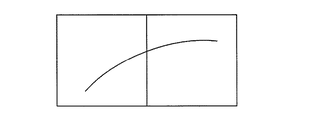
ステップ1:球面歪曲画像を複数の部分に分割する。説明の便宜上、以下の説明では仮にそのソリ曲線を含む画像を二つの部分に分けたとしても、実際はこれに限らず、一般的な状況下では、球面歪曲画像をさらに多くの部分に分割する。図1Aに示すように、直線は球面歪曲画像上にソリ曲線として現れている。 Step 1: Divide spherical distortion image into multiple parts. For convenience of explanation, in the following description, even if an image including the warp curve is divided into two parts, the present invention is not limited to this. In a general situation, a spherical distortion image is divided into more parts. As shown in FIG. 1A, the straight line appears as a warp curve on the spherical distortion image.
ステップ2:各部分の画像に対しそれぞれ補正を行い、歪みを除去する。補正後画像は単一視点撮像原理に適う。 Step 2: Correct each part of the image and remove the distortion. The corrected image is suitable for the single viewpoint imaging principle.
ステップ3:補正後のブロック画像に対し直線検出を行う。この時、補正後の画像は単一視点撮像原理に適うので、いかなる従来の検出方法(例えば従来のハフ直線変換方法を採用できる)でも採用でき、直線検出を行える。 Step 3: Straight line detection is performed on the corrected block image. At this time, since the corrected image is suitable for the single viewpoint imaging principle, any conventional detection method (for example, a conventional Hough straight line conversion method can be used) can be used, and straight line detection can be performed.
しかし、この種の従来の方法は少なくとも以下のいくつかの欠点がある。 However, this type of conventional method has at least some of the following disadvantages.
まず、直線の連続性を損なう。この時、二つのブロック画像上のソリ曲線に対してそれぞれ補正を行うことで、直線は画像補正後、図1Bに示すように遮断される可能性がある。また、補正後の直線の傾きも異なる可能性があり、これにより図1Cに示すように画像中で二段の直線に変わってしまう。当然ながら、研究者もこの問題について研究した後、いくつかの方法によって解決している。比較的よく用いられる方法は、同じエンドポイントを持つ直線に対して融合を行う方法である。具体的には、球面歪曲画像中の分割線上でエンドポイントが同じ線分については、補正後の二段の直線を一本の直線に属すると考える。しかし、この方法は他の問題が生じる。まず、こうした方法は現実には一本の直線に属していない同じエンドポイントを持つ二本の直線を一本の直線と誤認してしまう。例えば、図1Dに示すように、球面歪曲画像中に一つの壁の角があり、その一方の壁ともう一方の壁の上下の輪郭線は実際には一本の直線には属さないが、二本の直線は同じエンドポイントを持っている。この時、もし角がちょうど画像の分割線上にあると、システムはその一方の壁ともう一方の壁の上下の二本の輪郭線を一本の直線と誤認する可能性がある。 First, the continuity of the straight line is lost. At this time, by correcting each of the warp curves on the two block images, the straight line may be blocked as shown in FIG. 1B after the image correction. Also, the slope of the straight line after correction may be different, and this changes to a two-step straight line in the image as shown in FIG. 1C. Of course, researchers have also solved this problem in several ways after studying it. A relatively common method is to perform fusion on straight lines with the same end point. Specifically, for the line segment having the same end point on the dividing line in the spherical distortion image, the two-stage straight line after correction is considered to belong to one straight line. However, this method creates other problems. First, such a method mistakes two straight lines with the same end point that do not actually belong to a single straight line as a single straight line. For example, as shown in FIG.1D, there is a corner of one wall in the spherical distortion image, and the upper and lower contour lines of one wall and the other wall do not actually belong to one straight line, The two straight lines have the same end point. At this time, if the angle is just on the dividing line of the image, the system may mistake the two contour lines above and below the one wall and the other as a straight line.
次に、従来の直線検出方法を球面画像検出に応用すると、短めの直線を失ってしまう可能性がある。ノイズを低減するため、システムは長さが所定閾値より短い線をフィルタ・アウトする。すなわち、一本の直線の長さがその閾値より長い場合のみ、システムによって直線として検出される。図1Eに示すように、もし短めの直線が二段の直線に分けられた場合、それぞれ二つの部分に属する各直線がさらに短くなった後には容易に上述の所定閾値より短くなり、システムが検出できないようになってしまう。そうすると、こうした短めの直線は失われてしまう。 Next, if the conventional straight line detection method is applied to spherical image detection, a short straight line may be lost. To reduce noise, the system filters out lines whose length is less than a predetermined threshold. That is, only when the length of one straight line is longer than the threshold, it is detected as a straight line by the system. As shown in Fig.1E, if the short straight line is divided into two straight lines, each straight line belonging to each of the two parts will become shorter than the above-mentioned predetermined threshold value easily after each straight line becomes shorter and the system will detect It becomes impossible. Then, this short straight line is lost.
従来の直線検出方法は球面歪曲画像上でも従来のハフ直線変換方法を使用し続けるため、球面歪曲画像に対し分割及び補正をせざるを得ないことが分かる。ところがまさにこれらの分割のために画像中の直線は切断され、連続性は破壊されるか、あるいは直線がさらに短くなってシステムにノイズと誤認され、データは失われてしまう。よって、元画像に対し分割及び補正を行わない新しい直線検出方法が必要である。 Since the conventional straight line detection method continues to use the conventional Hough straight line conversion method even on a spherical distortion image, it can be understood that the spherical distortion image must be divided and corrected. However, just because of these divisions, the straight lines in the image are cut and the continuity is broken, or the straight lines become even shorter and the system misidentifies them as noise and data is lost. Therefore, a new straight line detection method that does not divide and correct the original image is necessary.
本発明は以上の課題を鑑みたものであり、画像に対して分割及び補正を行わずに、第一パラメータ空間に基づき直接球面歪曲画像上の直線を検出できる画像処理方法及び画像処理装置を提供することを目的とする。 The present invention has been made in view of the above problems, and provides an image processing method and an image processing apparatus capable of directly detecting a straight line on a spherical distortion image based on a first parameter space without performing division and correction on the image. The purpose is to do.
本発明の一つの実施例では、第一画像を取得するステップであって、直線は前記第一画像において所定球体の最大の円上のソリ曲線として現れる、ステップと、前記第一画像における複数の線を認識するステップと、第一パラメータ空間に基づき、前記線が直線であるか否かを決定するステップと、を含み、前記第一パラメータ空間における各点は前記所定球体の最大の円に対応し、前記第一画像における各点は前記第一パラメータ空間における最大の円に対応し、前記第一画像における同一直線上の複数の点に対応する複数の最大の円は前記第一パラメータ空間の所定の点で交わり、前記直線上に位置しない点に対応する最大の円は前記所定の点を通らない、画像処理方法を提供する。 In one embodiment of the present invention, obtaining a first image, wherein a straight line appears as a warp curve on a maximum circle of a predetermined sphere in the first image, and a plurality of steps in the first image Recognizing a line and determining whether the line is a straight line based on a first parameter space, each point in the first parameter space corresponding to a maximum circle of the predetermined sphere And each point in the first image corresponds to a maximum circle in the first parameter space, and a plurality of maximum circles corresponding to a plurality of points on the same straight line in the first image are in the first parameter space. An image processing method is provided in which a maximum circle corresponding to a point that intersects at a predetermined point and does not lie on the straight line does not pass through the predetermined point.
本発明の実施例は、第一画像を取得する画像取得モジュールであって、直線は前記第一画像において所定球体の最大の円上のソリ曲線として現れる、画像取得モジュールと、前記第一画像における複数の線を認識する線認識モジュールと、第一パラメータ空間に基づき、前記線が直線であるか否かを決定する直線検出モジュールと、を含み、前記第一パラメータ空間における各点は前記所定球体の最大の円に対応し、前記第一画像における各点は前記第一パラメータ空間における最大の円に対応し、前記第一画像における同一直線上の複数の点に対応する複数の最大の円は前記第一パラメータ空間の所定の点で交わり、前記直線上に位置しない点に対応する最大の円は前記所定の点を通らない、画像処理装置をさらに提供する。 An embodiment of the present invention is an image acquisition module for acquiring a first image, wherein the straight line appears as a warp curve on the largest circle of a predetermined sphere in the first image, and in the first image A line recognition module for recognizing a plurality of lines, and a line detection module for determining whether or not the line is a straight line based on the first parameter space, wherein each point in the first parameter space is the predetermined sphere , Each point in the first image corresponds to a maximum circle in the first parameter space, and a plurality of maximum circles corresponding to a plurality of points on the same straight line in the first image are There is further provided an image processing apparatus in which a maximum circle corresponding to a point that intersects at a predetermined point in the first parameter space and does not lie on the straight line does not pass through the predetermined point.
本発明の画像処理方法及び画像処理装置によれば、第一パラメータ空間を利用し、球面歪曲画像に対して直接的に直線検出を行い、その直線は球面歪曲画像上で所定球体の最大の円上のソリ曲線として現れ、第一パラメータ空間における各点は所定球体の最大の円に対応する。これによって、画像に対して分割及び補正を行うことなく、直接的に球面歪曲画像に対して直線検出を行うことができ、直線検出の過程で直線の連続性を損なうことなく、かつ短めの直線も検出することができる。 According to the image processing method and the image processing apparatus of the present invention, straight line detection is directly performed on a spherical distortion image using the first parameter space, and the straight line is the largest circle of a predetermined sphere on the spherical distortion image. Appearing as a warp curve above, each point in the first parameter space corresponds to the largest circle of a given sphere. This allows straight line detection to be performed directly on a spherically distorted image without dividing and correcting the image, and shortening straight lines without impairing the continuity of straight lines in the process of straight line detection. Can also be detected.
当業者が本発明の技術をより良く理解するため、以下は図面と合わせて本発明の画像処理方法及び画像処理装置の具体的な実施形態について詳細に説明する。当然ながら、本発明はこれに限定されず、当業者が創造的労働を行わない前提の下で取得するその他全ての実施例は、みな本発明の保護範囲に属する。 In order for those skilled in the art to better understand the technology of the present invention, the following describes in detail specific embodiments of the image processing method and the image processing apparatus of the present invention in conjunction with the drawings. Of course, the present invention is not limited to this, and all other embodiments obtained by a person skilled in the art under the premise that no creative labor is performed belong to the protection scope of the present invention.
(球面歪曲画像)
まず、図面を参照しながら本発明の球面歪曲画像を詳細に説明する。球面歪曲画像とは例えば広角レンズあるいはパノラマモードを用いて撮影した画像のことである。この時、レンズの焦点が小さいほど、あるいはパノラマモードの撮影範囲が大きいほど、歪みの程度は大きくなる。それでもし画像を超広角の魚眼レンズか、あるいは360°パノラマ画像を用いて撮影した場合、歪みの程度は非常に大きくなる。図2は球面歪曲画像を説明するための概略図である。図2に示すように、画像中に強い歪みが現れ、実際の直線が曲線に変わり、もはや単視点撮像の制約に適わないため、従来のハフ変換方法を使用して球面歪曲画像上の直線を検出することができない。
(Spherical distortion image)
First, the spherical distortion image of the present invention will be described in detail with reference to the drawings. A spherically distorted image is an image taken using, for example, a wide-angle lens or a panoramic mode. At this time, the degree of distortion increases as the focal point of the lens decreases or as the shooting range in the panorama mode increases. Still, if the image is taken with a super-wide angle fisheye lens or a 360 ° panoramic image, the degree of distortion is very large. FIG. 2 is a schematic diagram for explaining a spherical distortion image. As shown in Fig. 2, strong distortion appears in the image, the actual straight line turns into a curve, and it is no longer suitable for single-viewpoint imaging restrictions, so the straight line on the spherical distortion image is converted using the conventional Hough transform method. It cannot be detected.
このような球面歪曲画像は三次元の所定球体に投影できる。図3は球面歪曲画像を所定球体に投影することを説明するための概略図である。図3に示すように、図2の球面歪曲画像は一つの所定球体中に投影することができる。この時、歪みの程度が大きいほど、球体は小さくなる。球面歪曲画像上の各点の経度及び緯度の情報は以下の式によって単位球体上の三次元座標に換算できる。

式中、(lat、lon)は球面歪曲画像上の任意の一つの点の経度及び緯度を表し、(x、y、z)はそれぞれ単位球体上の三次元座標を表す。 In the equation, (lat, lon) represents the longitude and latitude of an arbitrary point on the spherical distortion image, and (x, y, z) represents the three-dimensional coordinates on the unit sphere.
同様に、単位球体上の任意の一つの点の三次元座標は以下の式によって元の球面歪曲画像上の経度及び緯度の情報に換算できる。
図4は直線が球面歪曲画像中でソリ曲線として表される原理を説明するための概略図である。図4に示すように、実際の直線l1は球面歪曲画像上で球面上の最大円C上のソリ曲線と撮像されるが、その中の最大円は球心を通る平面πと球体が交わって生じる円形である。 FIG. 4 is a schematic diagram for explaining the principle that a straight line is represented as a warp curve in a spherical distortion image. As shown in FIG. 4, the actual straight line l 1 is imaged as a warp curve on the maximum circle C on the sphere on the spherical distortion image, but the maximum circle in the plane intersects the plane π passing through the sphere and the sphere. The resulting circle.
(第一パラメータ空間)
続いて、図面を参照しながら第一パラメータ空間を詳細に説明する。第一パラメータ空間中の各点はその所定球体の最大円に対応する。上述したように、最大円は球心を通る平面πと球体が交わって生じる円形であり、したがってそれぞれの最大円は平面πに対応できる。図4に示すように、最大円に垂直な平面πにあるベクトルnにより第一パラメータ空間上の各点を表示できる。これで球面歪曲画像上の各点はすべて第一パラメータ空間上で一意に最大円にマッピングされ、球面歪曲画像中の直線は一意に所定球体の最大円に、すなわち第一パラメータ空間中の一点にマッピングされる。
(First parameter space)
Next, the first parameter space will be described in detail with reference to the drawings. Each point in the first parameter space corresponds to the maximum circle of the predetermined sphere. As described above, the maximum circle is a circle formed by the intersection of the plane π passing through the sphere and the sphere, and therefore each maximum circle can correspond to the plane π. As shown in FIG. 4, each point on the first parameter space can be displayed by a vector n in a plane π perpendicular to the maximum circle. Each point on the spherical distortion image is now uniquely mapped to the maximum circle in the first parameter space, and the straight line in the spherical distortion image is uniquely mapped to the maximum circle of the predetermined sphere, that is, one point in the first parameter space. To be mapped.
図5は本発明に係る第一パラメータ空間を説明するための概略図である。図5に示すように、方位角α及びピッチ角βを使用して第一パラメータ空間上の各点を表すことができ、-π≦α≦π、0≦β≦π/2となる。ここで、一つのベクトルnが決定する平面πとその反対のベクトル-nが決定する平面πは同じであるため、ピッチ角βの範囲は0≦β≦π/2でよい。注意すべき点として、その他の方式を使用して第一パラメータ空間上の各点を表すこともでき、第一パラメータ空間中の各点がその所定球体の最大円に対応してさえすればよい。この時、球面歪曲画像上の任意の一つの点P(xo,yo,zo)は一意に一意の最大円Cnにマッピングされる。
![]()
![]()
こうして第一パラメータ空間は二つの特性があると定義する。 Thus, the first parameter space is defined as having two characteristics.
1.同一直線上の複数の点に対応する複数の最大円は所定の点と交わる。 1. A plurality of maximum circles corresponding to a plurality of points on the same straight line intersect with a predetermined point.
2.直線上にない点に対応する最大円はその所定の点を通らない。 2. The maximum circle corresponding to a point that is not on a straight line does not pass through that point.
以下は図面を参照しながら二つの特性を詳細に説明する。 The following describes the two characteristics in detail with reference to the drawings.
第一の特性について、同一直線上の複数の点は第一パラメータ空間にマッピングされた後にそれぞれ複数の最大円となり、これら最大円は共通の交点(αo,βo)を持ち、かつこの交点は一意で球面上のこの直線で表示できる。
図6A、6Bは本発明に係る第一パラメータ空間の特性を説明するための概略図である。図6Aに示すように、直線l1上には3つの点p1、p2、p3がある。上述のように、球面歪曲画像上の各点は第一パラメータ空間上でそれぞれの一つの最大円にマッピングされるが、図6Bに示すように、これら3つの点は第一パラメータ空間中で3つの最大円が共通に持つ交点(αo,βo)にマッピングされる。よって同一直線l1上の3つの点p1、p2、p3に対応する3つの最大円は所定の点(αo,βo)と交わることが分かる。 6A and 6B are schematic diagrams for explaining the characteristics of the first parameter space according to the present invention. As shown in FIG. 6A, there are three points p 1 , p 2 , and p 3 on the straight line l 1 . As described above, each point on the spherical distortion image is mapped to one maximum circle on the first parameter space. However, as shown in FIG. It is mapped to the intersection (α o , β o ) that the two largest circles have in common. Therefore, it can be seen that the three maximum circles corresponding to the three points p 1 , p 2 , and p 3 on the same straight line l 1 intersect with the predetermined point (α o , β o ).
第二の特性について、図6A、6Bに示すように、球面歪曲画像上には直線l1とは異なる直線l2上の点p4があり、かつ点p4は第一パラメータ空間中で対応する最大円は、(αo,βo)を通らない。よって、直線l1上にない点に対応する最大円はその所定の点(αo,βo)を通らないことが分かる。 Regarding the second characteristic, as shown in FIGS. 6A and 6B, the spherical distortion image has a point p 4 on a straight line l 2 different from the straight line l 1 , and the point p 4 corresponds in the first parameter space. The maximum circle that does not pass through (α o , β o ). Therefore, it can be understood that the maximum circle corresponding to the point not on the straight line l 1 does not pass through the predetermined point (α o , β o ).
第一パラメータ空間のこれらの特性を利用して、直接的に球面歪曲画像上の直線検出ができ、画像に対する分割及び補正が不要なので、根本的に直線の連続性を保証でき、短めの直線が失われることもない。 Using these characteristics of the first parameter space, straight lines can be detected directly on the spherical distortion image, and there is no need to divide and correct the image, so the continuity of the straight line can be fundamentally guaranteed, and the shorter straight line It will not be lost.
(画像処理方法)
以下は図面を参照しながら本発明の画像処理方法を詳細に説明する。図7は本発明に係る実施例の画像処理方法のフローチャートである。図7に示すように、当該方法には以下が含まれる。
(Image processing method)
The image processing method of the present invention will be described in detail below with reference to the drawings. FIG. 7 is a flowchart of the image processing method according to the embodiment of the present invention. As shown in FIG. 7, the method includes:
まず、球面歪曲画像(ステップS710)を取得する。球面歪曲画像は例えば超広角レンズあるいはパノラマモードにより取得した画像である。上述したように、実際の直線は球体歪み画像上所定球体の最大円上のソリ曲線としてレンダリングされる(現れる)。通常の状況下で、球面歪曲画像中の各点の座標は経緯度で表す。 First, a spherical distortion image (step S710) is acquired. The spherically distorted image is an image obtained by using, for example, a super wide-angle lens or a panorama mode. As described above, an actual straight line is rendered (appears) as a warp curve on the maximum circle of a predetermined sphere on the sphere distortion image. Under normal circumstances, the coordinates of each point in the spherical distortion image are represented by longitude and latitude.
続いて、その球面歪曲画像中の複数の線を認識する(ステップS720)。複数の線は球面歪曲画像中の対象のエッジ情報から取得でき、これにより図2に示すような線画像を取得できる。Canny演算子あるいはSobel演算子等、いかなる従来の方法を用いてもエッジ検出を行うことができるので、その詳細についてはここでは述べない。 Subsequently, a plurality of lines in the spherical distortion image are recognized (step S720). A plurality of lines can be acquired from the edge information of the object in the spherical distortion image, and thereby a line image as shown in FIG. 2 can be acquired. Edge detection can be performed using any conventional method such as Canny operator or Sobel operator, and details thereof will not be described here.
最後に、第一パラメータ空間に基づき前記線が直線であるか否かを決定する(ステップS730)。上述のように、球面歪曲画像は三次元の所定球体に投影され、かつ実際の直線は球面歪曲画像上で所定球体上の最大円上のソリ曲線としてレンダリングされる。よって、認識した線が第一パラメータ空間中のある一点に対応する最大円上のソリ曲線でありさえすれば、当該の線が実際に直線であると決定できる。 Finally, it is determined based on the first parameter space whether or not the line is a straight line (step S730). As described above, the spherical distortion image is projected onto a three-dimensional predetermined sphere, and the actual straight line is rendered as a warp curve on the maximum circle on the predetermined sphere on the spherical distortion image. Therefore, as long as the recognized line is a warp curve on the maximum circle corresponding to a certain point in the first parameter space, it can be determined that the line is actually a straight line.
第一パラメータ空間の特性に基づき、同一直線上の複数の点に対応する複数の最大円は所定の点に交わり、かつ直線上に位置しない点に対応する最大円は当該所定の点を通らない。よって、ある線が直線か否かを判断する時、当該直線から複数のエッジ点を抽出し、その後再び第一パラメータ空間の特性に基づきこれらのエッジ点が対応する最大円が所定の点を通るか否か判断し、それにより複数の特定のエッジ点が特定の直線上にあるか否かを決定できる。 Based on the characteristics of the first parameter space, a plurality of maximum circles corresponding to a plurality of points on the same straight line intersect a predetermined point, and a maximum circle corresponding to a point not located on the straight line does not pass through the predetermined point . Therefore, when determining whether or not a certain line is a straight line, a plurality of edge points are extracted from the straight line, and then the maximum circle corresponding to these edge points again passes a predetermined point based on the characteristics of the first parameter space. Whether or not a plurality of specific edge points are on a specific straight line can be determined.
具体的に言えば、式(1)により球面歪曲画像上の各エッジ点の経度及び緯度を球体上の三次元座標に変換でき、かつ以下の処理を行う。 More specifically, the longitude and latitude of each edge point on the spherical distortion image can be converted into three-dimensional coordinates on the sphere by the equation (1), and the following processing is performed.
まず、球面歪曲画像上の各点はすべて第一パラメータ空間中の一つの最大円に対応するので、式(4)により第一パラメータ空間中の各エッジ点に対応する最大円のベクトルの集合を取得できる。ここで、各最大円上には無限のベクトルがあるものの、計算し易くするため、これら無限のベクトルを離散化し、所定の間隔に従って値を取ることができる。例えば、方位角α及びピッチ角βはすべて1°の間隔で値を取り、こうしてベクトルの集合を取得する。 First, since each point on the spherical distortion image corresponds to one maximum circle in the first parameter space, a set of vectors of the maximum circle corresponding to each edge point in the first parameter space is obtained by equation (4). You can get it. Here, although there are infinite vectors on each maximum circle, in order to facilitate calculation, these infinite vectors can be discretized and values can be taken according to a predetermined interval. For example, the azimuth angle α and the pitch angle β all take values at intervals of 1 °, thus obtaining a set of vectors.
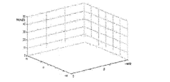
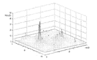
その後、前記の複数のエッジ点に対し前記第一パラメータ空間内の各ベクトルの累計数を統計する。この時、累積行列を使用してこれら最大円が第一パラメータ空間中で一点に交わるか否か検証できる。図8は統計した第一パラメータ空間内の各ベクトルの累計数の累計行列である。図8に示すように、累積行列のX軸及びY軸はそれぞれ第一パラメータ空間の各一点(ベクトル)の方位角α及びピッチ角βを表すことができ、-π≦α≦π、0≦β≦π/2となる。Z軸は累積数を表すことができる。例えば、30個のエッジ点を取り出し、かつこれらのエッジ点が特定の直線上にあるか否かを判断する時、式(4)によってこの30個のエッジ点に対応する30個の最大円を取得し、かつこれら最大円を順次累積行列の中に蓄積することができる。具体的には、上述の離散化したベクトルの集合を上述の累積行列の中に表すことができる。球面歪曲画像上の各点は第一パラメータ空間の最大円に対応するので、離散化された当該の最大円は累積行列の中で複数の点として表示され、図9に示すように、それぞれの点は一つのベクトルを代表する。この30個のエッジ点に対応するベクトルの集合を順次累積行列の中に追加し、パラメータ(α、β)が一回出現するたびに、累積行列中の(α、β)がZ軸上で一つ加わり、このようにして最終的に図10に示すような累積行列を取得できる。取り出すエッジ点の数は30個に限らず、他のいかなる数のエッジ点でも取り出してよいことは言うまでもない。 Thereafter, the cumulative number of vectors in the first parameter space is statistically calculated for the plurality of edge points. At this time, it is possible to verify whether or not these maximum circles intersect at a point in the first parameter space using the cumulative matrix. FIG. 8 is a cumulative matrix of the cumulative number of each vector in the statistical first parameter space. As shown in FIG. 8, the X-axis and Y-axis of the cumulative matrix can respectively represent the azimuth angle α and pitch angle β of each point (vector) in the first parameter space, and −π ≦ α ≦ π, 0 ≦ β ≦ π / 2. The Z axis can represent cumulative numbers. For example, when 30 edge points are extracted and it is determined whether or not these edge points are on a specific straight line, 30 maximum circles corresponding to these 30 edge points are calculated by equation (4). And obtain these maximum circles sequentially in a cumulative matrix. Specifically, the set of discretized vectors described above can be represented in the cumulative matrix described above. Since each point on the spherical distortion image corresponds to the maximum circle in the first parameter space, the discretized maximum circle is displayed as a plurality of points in the cumulative matrix, and as shown in FIG. A point represents one vector. A set of vectors corresponding to the 30 edge points is sequentially added to the cumulative matrix, and every time the parameter (α, β) appears once, (α, β) in the cumulative matrix is changed on the Z axis. In this way, a cumulative matrix as shown in FIG. 10 can be finally obtained. Needless to say, the number of edge points to be extracted is not limited to 30, and any other number of edge points may be extracted.
最後に、累積数が所定閾値よりも大きいベクトルに対応するエッジ点の集合を特定の直線上にあるものとして決定する。Z軸はベクトルの累積数を表すので、累積の高さが高いほど、さらに多くの最大円がその点で交わることを意味する。第一パラメータ空間の特性に基づき、同一直線上の複数のエッジ点に対応する複数の最大円は所定の点で交わるので、所定の閾値を設定し、かつ複数のエッジ点がその対応する最大円とその点(すなわちその点の方位角α及びピッチ角βに対応する第一パラメータ空間上のベクトル)で交わる数が所定閾値よりも大きい場合、その点に対応するエッジ点の集合を特定の直線上にあるものと決定できる。 Finally, a set of edge points corresponding to vectors whose cumulative number is greater than a predetermined threshold is determined as being on a specific straight line. Since the Z axis represents the cumulative number of vectors, the higher the cumulative height, the more maximum circles intersect at that point. Based on the characteristics of the first parameter space, a plurality of maximum circles corresponding to a plurality of edge points on the same straight line intersect at a predetermined point, so a predetermined threshold is set, and a plurality of edge points correspond to the corresponding maximum circle And the point (that is, the vector in the first parameter space corresponding to the azimuth angle α and the pitch angle β of the point) is greater than a predetermined threshold, a set of edge points corresponding to the point is defined as a specific straight line. It can be determined that it is above.
その他、上述の方法により第一パラメータ空間に基づき複数のエッジが特定の直線上にあるか否かを決定した後、球面歪曲画像上に決定した特定の直線を表示できる。例えば、上述の処理により複数のエッジ点が特定の直線に属することを決定した後、式(2)によりこれらエッジ点の三次元座標を球面歪曲画像上の経緯度に変換し、かつ特定の色を使用し球面歪曲画像上でこれらのエッジ点を表し、これによりユーザーに対し決定した特定の直線をレンダリングすることができる。 In addition, after determining whether or not a plurality of edges are on a specific straight line based on the first parameter space by the above-described method, the specific straight line determined on the spherical distortion image can be displayed. For example, after determining that a plurality of edge points belong to a specific straight line by the above-described processing, the three-dimensional coordinates of these edge points are converted into longitude and latitude on the spherical distortion image by formula (2), and a specific color Can be used to represent these edge points on a spherically distorted image, thereby rendering a specific straight line determined for the user.
以上の方法により、画像に対して分割及び補正を行うことなく、第一パラメータ空間に基づき直接的に球面歪曲画像上の直線を検出できるので、直線検出の過程で直線の連続性を損なうことなく、かつ短めの直線も検出することができる。 By the above method, it is possible to directly detect a straight line on the spherical distortion image based on the first parameter space without dividing and correcting the image, so that the continuity of the straight line is not impaired in the process of detecting the straight line. In addition, a short straight line can be detected.
以上、本発明の画像処理方法の多数の実施例を説明した。当業者であれば本発明の精神と範囲内を逸脱することなく上述の実施例に対して様々な組み合わせ、修正あるいは変形を行うことが可能であるのは言うまでもない。当業者が創造的労働を行わない前提の下で取得するその他全ての実施例は、みな本発明の保護範囲に属する。 In the foregoing, a number of embodiments of the image processing method of the present invention have been described. It goes without saying that those skilled in the art can make various combinations, modifications, and variations on the above-described embodiments without departing from the spirit and scope of the present invention. All other embodiments obtained by the person skilled in the art under the premise of not performing creative labor are all within the scope of protection of the present invention.
(画像処理装置)
以下は図面を参照しながら本発明の画像処理装置について詳細に説明する。本発明の画像処理装置は例えばデジタルカメラ、ドライブレコーダー等の撮像機能を主とする装置でよく、スマートフォン、タブレットパソコン等の撮像機能を備える演算機能を主とする装置でもよく、また撮像機能を備えない単純な画像処理装置でもよく、球面歪曲画像を取得出来さえすればよい。
(Image processing device)
Hereinafter, the image processing apparatus of the present invention will be described in detail with reference to the drawings. The image processing apparatus of the present invention may be an apparatus mainly having an imaging function such as a digital camera or a drive recorder, or may be an apparatus mainly having an arithmetic function having an imaging function such as a smartphone or a tablet personal computer, and also has an imaging function. A simple image processing apparatus may be used as long as a spherical distortion image can be acquired.
図11は本発明の実施例に基づく画像処理装置の機能ブロック図である。図11に示すように、本発明の画像処理装置1100は、画像取得モジュール1110、線認識モジュール1120及び直線検出モジュール1130を含む。
FIG. 11 is a functional block diagram of the image processing apparatus according to the embodiment of the present invention. As shown in FIG. 11, the
以下は図面と合わせて本発明の画像処理装置の各モジュールの操作を詳細に説明する。 Hereinafter, the operation of each module of the image processing apparatus of the present invention will be described in detail with reference to the drawings.
画像取得モジュール1110は球面歪曲画像を取得する。球面歪曲画像は例えば超広角レンズあるいはパノラマモードにより取得した画像である。画像処理装置がデジタルカメラなど撮影機能を主とする設備、あるいは撮影機能を備える他の設備である時、当該画像処理装置上のカメラにより球面歪曲画像を取り込むことができる。当然ながら、画像処理装置は他の設備あるいは記憶装置中から球面歪曲画像を取得することもできる。上述したように、実際の直線は球面歪曲画像上で所定球体の最大円上のソリ曲線としてレンダリングされる。通常の状況下で、球面歪曲画像中の各点の座標は経緯度で表す。
The
線認識モジュール1120は当該球面歪曲画像中の複数の線を認識する。複数の線は球面歪曲画像中の対象のエッジ情報から抽出することができ、それにより図2に示す線画像を取得できる。Canny演算子またはSobel演算子等、いかなる従来の方法を用いてもエッジ検出を行うことができるので、その詳細についてはここでは述べない。
The
直線検出モジュール1130は第一パラメータ空間に基づいてその線が直線であるか否かを決定する。上述したように、球面歪曲画像は三次元の所定球体に投影でき、かつ実際の直線は球面歪曲画像上で所定球体の最大円上のソリ曲線としてレンダリングされる。よって認識した線が第一パラメータ空間中のある一点に対応する最大円上のソリ曲線でありさえすれば、その線が実際に直線であると決定できる。
The straight
第一パラメータ空間の特性に基づき、同一直線上の複数の点に対応する複数の最大円は所定の点と交わり、かつ直線上に位置しない点に対応する最大円はその所定の点を通らない。よって、ある線が直線であるか否か判断する時、当該の線から複数のエッジ点を抽出し、その後再び第一パラメータ空間の特性に基づきこれらのエッジ点が対応する最大円が所定の点を通るか否か判断し、これにより複数の特定のエッジ点が特定の直線上にあるか否かを決定できる。 Based on the characteristics of the first parameter space, a plurality of maximum circles corresponding to a plurality of points on the same straight line intersect with a predetermined point, and a maximum circle corresponding to a point not located on the straight line does not pass through the predetermined point . Therefore, when determining whether or not a certain line is a straight line, a plurality of edge points are extracted from the line, and the maximum circle corresponding to these edge points is again a predetermined point based on the characteristics of the first parameter space. Whether or not a plurality of specific edge points are on a specific straight line can be determined.
具体的には、式(1)により球面歪曲画像上のエッジ点それぞれの経度及び緯度を球体上の三次元座標に変換し、かつ以下の処理を行う。 Specifically, the longitude and latitude of each edge point on the spherical distortion image are converted into the three-dimensional coordinates on the sphere by the equation (1), and the following processing is performed.
まず、球面歪曲画像上の各点はすべて第一パラメータ空間中の一つの最大円に対応するので、式(4)により第一パラメータ空間中の各エッジ点に対応する最大円のベクトルの集合を取得できる。ここで、各最大円上には無限のベクトルがあるものの、計算し易くするため、これら無限のベクトルを離散化し、所定の間隔に従って値を取ることができる。例えば、方位角α及びピッチ角βはすべて1°の間隔で値を取り、こうしてベクトルの集合を取得する。 First, since each point on the spherical distortion image corresponds to one maximum circle in the first parameter space, a set of vectors of the maximum circle corresponding to each edge point in the first parameter space is obtained by equation (4). You can get it. Here, although there are infinite vectors on each maximum circle, in order to facilitate calculation, these infinite vectors can be discretized and values can be taken according to a predetermined interval. For example, the azimuth angle α and the pitch angle β all take values at intervals of 1 °, thus obtaining a set of vectors.
その後、その複数のエッジ点に対し前記第一パラメータ空間内の各ベクトルの累計数を統計する。この時、累積行列を使用してこれら最大円が第一パラメータ空間中で一点に交わるか否か検証できる。図8は統計した第一パラメータ空間内の各ベクトルの累計数の累計行列である。図8に示すように、累積行列のX軸及びY軸はそれぞれ第一パラメータ空間の各一点(ベクトル)の方位角α及びピッチ角βを表すことができ、-π≦α≦π、0≦β≦π/2となる。Z軸は累積数を表すことができる。例えば、30個のエッジ点を取り出し、かつこれらのエッジ点が特定の直線上にあるか否かを判断する時、式(4)によってこの30個のエッジ点に対応する30個の最大円を取得し、かつこれら最大円を順次累積行列の中に蓄積することができる。具体的には、上述の離散化したベクトルの集合を上述の累積行列の中に表すことができる。球面歪曲画像上の各点は第一パラメータ空間の最大円に対応するので、離散化された当該の最大円は累積行列の中で複数の点として表示され、図9に示すように、それぞれの点は一つのベクトルを代表する。この30個のエッジ点に対応するベクトルの集合を順次累積行列の中に追加し、パラメータ(α、β)が一回出現するたびに、累積行列中の(α、β)がZ軸上で一つ加わり、このようにして最終的に図10に示すような累積行列を取得できる。取り出すエッジ点の数は30個に限らず、他のいかなる数のエッジ点でも取り出してよいことは言うまでもない。 Thereafter, the cumulative number of vectors in the first parameter space is statistically calculated for the plurality of edge points. At this time, it is possible to verify whether or not these maximum circles intersect at a point in the first parameter space using the cumulative matrix. FIG. 8 is a cumulative matrix of the cumulative number of each vector in the statistical first parameter space. As shown in FIG. 8, the X-axis and Y-axis of the cumulative matrix can respectively represent the azimuth angle α and pitch angle β of each point (vector) in the first parameter space, and −π ≦ α ≦ π, 0 ≦ β ≦ π / 2. The Z axis can represent cumulative numbers. For example, when 30 edge points are extracted and it is determined whether or not these edge points are on a specific straight line, 30 maximum circles corresponding to these 30 edge points are calculated by equation (4). And obtain these maximum circles sequentially in a cumulative matrix. Specifically, the set of discretized vectors described above can be represented in the cumulative matrix described above. Since each point on the spherical distortion image corresponds to the maximum circle in the first parameter space, the discretized maximum circle is displayed as a plurality of points in the cumulative matrix, and as shown in FIG. A point represents one vector. A set of vectors corresponding to the 30 edge points is sequentially added to the cumulative matrix, and every time the parameter (α, β) appears once, (α, β) in the cumulative matrix is changed on the Z axis. In this way, a cumulative matrix as shown in FIG. 10 can be finally obtained. Needless to say, the number of edge points to be extracted is not limited to 30, and any other number of edge points may be extracted.
最後に、累積数が所定閾値を上回るベクトルに対応するエッジ点の集合を特定の直線上にあるものとして決定する。Z軸はベクトルの累積数を表すので、累積の高さが高いほど、さらに多くの最大円がその点で交わることを意味する。第一パラメータ空間の特性に基づき、同一直線上の複数のエッジ点に対応する複数の最大円は所定の点で交わるので、所定の閾値を設定し、かつ複数のエッジ点がその対応する最大円とその点(すなわちその点の方位角α及びピッチ角βに対応する第一パラメータ空間上のベクトル)で交わる数が所定閾値よりも大きい場合、当該点に対応するエッジ点の集合を特定の直線上にあるものとして決定できる。 Finally, a set of edge points corresponding to vectors whose cumulative number exceeds a predetermined threshold is determined as being on a specific straight line. Since the Z axis represents the cumulative number of vectors, the higher the cumulative height, the more maximum circles intersect at that point. Based on the characteristics of the first parameter space, a plurality of maximum circles corresponding to a plurality of edge points on the same straight line intersect at a predetermined point, so a predetermined threshold is set, and a plurality of edge points correspond to the corresponding maximum circle And the point (that is, the vector in the first parameter space corresponding to the azimuth angle α and the pitch angle β of the point) is greater than a predetermined threshold, a set of edge points corresponding to the point is defined as a specific straight line. It can be determined as being above.
その他、画像処理装置1100はさらにレンダリング(表示)モジュールを含み、第一パラメータ空間に基づき複数のエッジが特定の直線上にあるか否かを決定した後、球面歪曲画像上にその決定した特定の直線をレンダリング(表示)する。例えば、上述の処理により複数のエッジ点が特定の直線に属することを決定した後、式(2)によりこれらエッジ点の三次元座標を球面歪曲画像上の経緯度に変換し、かつ特定の色を使用し球面歪曲画像上でこれらのエッジ点を表し、これによりユーザーに対し決定した特定の直線をレンダリングすることができる。
In addition, the
以上の処理により、画像に対して分割及び補正を行うことなく、第一パラメータ空間に基づき直接的に球面歪曲画像上の直線を検出できるので、直線検出の過程で直線の連続性を損なうことなく、かつ短めの直線も検出することができる。 With the above processing, straight lines on the spherical distortion image can be detected directly based on the first parameter space without dividing and correcting the image, so that the continuity of straight lines is not impaired in the process of straight line detection. In addition, a short straight line can be detected.
以上の実施方式の説明によって、当業者であれば本発明はソフトウェアに不可欠なハードウェアを加えたプラットホームの方法で実現できること、また当然すべてをハードウェアによって実施できることもはっきり理解できる。こうした理解に基づき、本発明の技術案は背景技術が寄与するすべてあるいは一部に対してソフトウェア製品の形式で実現でき、当該コンピュータソフトウェア製品はROM/RAM、磁気ディスク、コンパクトディスクのような記憶媒体に記憶でき、幾らかのコマンドを含んだコンピュータ機器(パーソナルコンピュータ、サーバ、あるいはネットワークデバイスなどでよい)に本発明の各実施例あるいは実施例のある部分の方法を実行させることができる。 From the above description of the implementation method, those skilled in the art can clearly understand that the present invention can be realized by a platform method in which hardware essential to software is added, and that all can be implemented by hardware. Based on this understanding, the technical solution of the present invention can be realized in the form of a software product for all or part of the contribution of the background technology, and the computer software product can be a storage medium such as a ROM / RAM, a magnetic disk, or a compact disk. The computer apparatus (which may be a personal computer, a server, a network device, or the like) that can be stored in a computer and that includes some commands can execute the method of each embodiment of the present invention or a part of the embodiment.
以上、本発明の画像処理装置の多数の実施例を説明した。明らかに、当業者は本発明の精神及び範囲内を逸脱することなく上述の実施例に対して様々な組み合わせ、修正あるいは変形を行うことができる。当業者が創造的労働を行わない前提の下で取得したその他すべての実施例は、みな本発明の保護範囲に属する。 In the foregoing, a number of embodiments of the image processing apparatus of the present invention have been described. Obviously, those skilled in the art can make various combinations, modifications, and variations on the above-described embodiments without departing from the spirit and scope of the invention. All other examples obtained under the premise that the person skilled in the art does not perform creative labor belong to the protection scope of the present invention.
Claims (12)
前記第一画像における複数の線を認識するステップと、
第一パラメータ空間に基づき、前記線が直線であるか否かを決定するステップと、を含み、
前記第一パラメータ空間における各点は前記所定球体の最大の円に対応し、前記第一画像における各点は前記第一パラメータ空間における最大の円に対応し、前記第一画像における同一直線上の複数の点に対応する複数の最大の円は前記第一パラメータ空間の所定の点で交わり、前記直線上に位置しない点に対応する最大の円は前記所定の点を通らない、画像処理方法。 Obtaining a first image, wherein a straight line appears as a warp curve on a maximum circle of a predetermined sphere in the first image; and
Recognizing a plurality of lines in the first image;
Determining whether the line is a straight line based on a first parameter space; and
Each point in the first parameter space corresponds to the largest circle of the predetermined sphere, each point in the first image corresponds to the largest circle in the first parameter space, and is collinear in the first image A plurality of maximum circles corresponding to a plurality of points intersect at a predetermined point in the first parameter space, and a maximum circle corresponding to a point not located on the straight line does not pass through the predetermined point.
前記線から複数のエッジ点を抽出するステップと、
第一パラメータ空間に基づき、複数の特定のエッジ点が特定の直線上にあるか否かを決定するステップと、を含む、請求項1に記載の画像処理方法。 Based on the first parameter space, determining whether the line is a straight line,
Extracting a plurality of edge points from the line;
The image processing method according to claim 1, further comprising: determining whether a plurality of specific edge points are on a specific straight line based on the first parameter space.
前記第一パラメータ空間における前記エッジ点に対応する最大の円のベクトルの集合を取得するステップと、
前記複数のエッジ点に対して前記第一パラメータ空間内の各ベクトルの累積数を統計するステップと、
累積数が所定閾値よりも大きいベクトルに対応するエッジ点の集合を特定の直線上にあるものとして決定するステップと、を含む、請求項3に記載の画像処理方法。 Determining whether a plurality of specific edge points are on a specific straight line based on the first parameter space,
Obtaining a vector set of maximum circles corresponding to the edge points in the first parameter space;
Statistics the cumulative number of each vector in the first parameter space for the plurality of edge points;
The image processing method according to claim 3, further comprising: determining a set of edge points corresponding to a vector having a cumulative number greater than a predetermined threshold as being on a specific straight line.
前記第一画像において、決定された特定の直線を表示するステップ、をさらに含む、請求項3に記載の画像処理方法。 Based on the first parameter space, after determining whether a plurality of specific edge points are on a specific straight line,
The image processing method according to claim 3, further comprising: displaying the determined specific straight line in the first image.
前記第一画像における複数の線を認識する線認識モジュールと、
第一パラメータ空間に基づき、前記線が直線であるか否かを決定する直線検出モジュールと、を含み、
前記第一パラメータ空間における各点は前記所定球体の最大の円に対応し、前記第一画像における各点は前記第一パラメータ空間における最大の円に対応し、前記第一画像における同一直線上の複数の点に対応する複数の最大の円は前記第一パラメータ空間の所定の点で交わり、前記直線上に位置しない点に対応する最大の円は前記所定の点を通らない、画像処理装置。 An image acquisition module for acquiring a first image, wherein the straight line appears as a warp curve on a maximum circle of a predetermined sphere in the first image;
A line recognition module for recognizing a plurality of lines in the first image;
A straight line detection module for determining whether the line is a straight line based on a first parameter space;
Each point in the first parameter space corresponds to the largest circle of the predetermined sphere, each point in the first image corresponds to the largest circle in the first parameter space, and is collinear in the first image A plurality of maximum circles corresponding to a plurality of points intersect at a predetermined point in the first parameter space, and a maximum circle corresponding to a point not on the straight line does not pass through the predetermined point.
前記第一画像における複数の線を認識するステップと、
第一パラメータ空間に基づき、前記線が直線であるか否かを決定するステップと、をコンピュータに実行させるためのプログラムであって、
前記第一パラメータ空間における各点は前記所定球体の最大の円に対応し、前記第一画像における各点は前記第一パラメータ空間における最大の円に対応し、前記第一画像における同一直線上の複数の点に対応する複数の最大の円は前記第一パラメータ空間の所定の点で交わり、前記直線上に位置しない点に対応する最大の円は前記所定の点を通らない、プログラム。 Obtaining a first image, wherein a straight line appears as a warp curve on a maximum circle of a predetermined sphere in the first image; and
Recognizing a plurality of lines in the first image;
Determining whether the line is a straight line based on a first parameter space, and causing a computer to execute the program,
Each point in the first parameter space corresponds to the largest circle of the predetermined sphere, each point in the first image corresponds to the largest circle in the first parameter space, and is collinear in the first image A plurality of maximum circles corresponding to a plurality of points intersect at a predetermined point in the first parameter space, and a maximum circle corresponding to a point not located on the straight line does not pass through the predetermined point.
前記第一画像における複数の線を認識するステップと、
第一パラメータ空間に基づき、前記線が直線であるか否かを決定するステップと、をコンピュータに実行させるためのプログラムを記録したコンピュータ読み取り可能な記録媒体であって、
前記第一パラメータ空間における各点は前記所定球体の最大の円に対応し、前記第一画像における各点は前記第一パラメータ空間における最大の円に対応し、前記第一画像における同一直線上の複数の点に対応する複数の最大の円は前記第一パラメータ空間の所定の点で交わり、前記直線上に位置しない点に対応する最大の円は前記所定の点を通らない、記録媒体。 Obtaining a first image, wherein a straight line appears as a warp curve on a maximum circle of a predetermined sphere in the first image; and
Recognizing a plurality of lines in the first image;
A step of determining whether the line is a straight line based on a first parameter space, and a computer-readable recording medium recording a program for causing a computer to execute the method,
Each point in the first parameter space corresponds to the largest circle of the predetermined sphere, each point in the first image corresponds to the largest circle in the first parameter space, and is collinear in the first image A plurality of maximum circles corresponding to a plurality of points intersect at a predetermined point in the first parameter space, and a maximum circle corresponding to a point not located on the straight line does not pass through the predetermined point.
Applications Claiming Priority (2)
| Application Number | Priority Date | Filing Date | Title |
|---|---|---|---|
| CN201510357670.3A CN106296645A (en) | 2015-06-25 | 2015-06-25 | Image processing method and image processing apparatus |
| CN201510357670.3 | 2015-06-25 |
Publications (1)
| Publication Number | Publication Date |
|---|---|
| JP2017010555A true JP2017010555A (en) | 2017-01-12 |
Family
ID=57650935
Family Applications (1)
| Application Number | Title | Priority Date | Filing Date |
|---|---|---|---|
| JP2016121586A Pending JP2017010555A (en) | 2015-06-25 | 2016-06-20 | Image processing method and image processing apparatus |
Country Status (2)
| Country | Link |
|---|---|
| JP (1) | JP2017010555A (en) |
| CN (1) | CN106296645A (en) |
Families Citing this family (1)
| Publication number | Priority date | Publication date | Assignee | Title |
|---|---|---|---|---|
| CN107016700B (en) * | 2017-04-14 | 2019-06-25 | 中国科学院合肥物质科学研究院 | A kind of Circle Detection method based on digital picture |
Citations (6)
| Publication number | Priority date | Publication date | Assignee | Title |
|---|---|---|---|---|
| JPS60218183A (en) * | 1984-04-13 | 1985-10-31 | Fujitsu Ltd | Information extracting method based upon mapping |
| US4736436A (en) * | 1984-04-13 | 1988-04-05 | Fujitsu Limited | Information extraction by mapping |
| JPH0896131A (en) * | 1994-09-28 | 1996-04-12 | Nec Corp | Method and device for detecting figure |
| JP2009288885A (en) * | 2008-05-27 | 2009-12-10 | Tottori Univ | Lane detection device, lane detection method and lane detection program |
| JP2013084221A (en) * | 2011-10-12 | 2013-05-09 | Tottori Univ | Straight line detecting device, straight line detecting method, straight line detecting program, and photographing system |
| JP2014092922A (en) * | 2012-11-02 | 2014-05-19 | Tottori Univ | Detector, detection method, and detection program |
Family Cites Families (4)
| Publication number | Priority date | Publication date | Assignee | Title |
|---|---|---|---|---|
| JPH0719832A (en) * | 1993-06-21 | 1995-01-20 | Canon Inc | Extracting method for corresponding points of pulirity of images |
| CN102184536B (en) * | 2011-04-19 | 2013-07-10 | 清华大学 | Method and system for extracting straight line and/or line segment end points from image |
| CN102385750B (en) * | 2011-06-22 | 2013-07-10 | 清华大学 | Line matching method and line matching system on basis of geometrical relationship |
| CN104268867B (en) * | 2014-09-22 | 2017-12-12 | 国家电网公司 | A kind of adaptive fish eye lens method for quickly correcting |
-
2015
- 2015-06-25 CN CN201510357670.3A patent/CN106296645A/en active Pending
-
2016
- 2016-06-20 JP JP2016121586A patent/JP2017010555A/en active Pending
Patent Citations (6)
| Publication number | Priority date | Publication date | Assignee | Title |
|---|---|---|---|---|
| JPS60218183A (en) * | 1984-04-13 | 1985-10-31 | Fujitsu Ltd | Information extracting method based upon mapping |
| US4736436A (en) * | 1984-04-13 | 1988-04-05 | Fujitsu Limited | Information extraction by mapping |
| JPH0896131A (en) * | 1994-09-28 | 1996-04-12 | Nec Corp | Method and device for detecting figure |
| JP2009288885A (en) * | 2008-05-27 | 2009-12-10 | Tottori Univ | Lane detection device, lane detection method and lane detection program |
| JP2013084221A (en) * | 2011-10-12 | 2013-05-09 | Tottori Univ | Straight line detecting device, straight line detecting method, straight line detecting program, and photographing system |
| JP2014092922A (en) * | 2012-11-02 | 2014-05-19 | Tottori Univ | Detector, detection method, and detection program |
Also Published As
| Publication number | Publication date |
|---|---|
| CN106296645A (en) | 2017-01-04 |
Similar Documents
| Publication | Publication Date | Title |
|---|---|---|
| CN110717942B (en) | Image processing method and device, electronic equipment and computer readable storage medium | |
| CN106846409B (en) | Calibration method and device of fisheye camera | |
| CN103517041B (en) | Based on real time panoramic method for supervising and the device of polyphaser rotation sweep | |
| WO2017054314A1 (en) | Building height calculation method and apparatus, and storage medium | |
| US10909719B2 (en) | Image processing method and apparatus | |
| CN111368717B (en) | Line-of-sight determination method, line-of-sight determination device, electronic apparatus, and computer-readable storage medium | |
| CN107798702B (en) | Real-time image superposition method and device for augmented reality | |
| US20190378294A1 (en) | Stereo camera and height acquisition method thereof and height acquisition system | |
| CN108280386B (en) | Monitoring scene detection method and device | |
| WO2022105415A1 (en) | Method, apparatus and system for acquiring key frame image, and three-dimensional reconstruction method | |
| CN111062234A (en) | Monitoring method, intelligent terminal and computer readable storage medium | |
| WO2021008205A1 (en) | Image processing | |
| CN109120854B (en) | Image processing method, image processing device, electronic equipment and storage medium | |
| US9613404B2 (en) | Image processing method, image processing apparatus and electronic device | |
| CN108734738B (en) | Camera calibration method and device | |
| CN108717704B (en) | Target tracking method based on fisheye image, computer device and computer readable storage medium | |
| CN111598777A (en) | Sky cloud image processing method, computer device and readable storage medium | |
| CN114331860A (en) | Distorted image correction method and positioning method thereof | |
| JPWO2019069469A1 (en) | Object detection device, object detection method, and program | |
| JP6677980B2 (en) | Panorama video data processing device, processing method and processing program | |
| CN111353945B (en) | Fisheye image correction method, device and storage medium | |
| JP2017010555A (en) | Image processing method and image processing apparatus | |
| CN115880643A (en) | Social distance monitoring method and device based on target detection algorithm | |
| CN112328150B (en) | Automatic screenshot method, device and equipment, and storage medium | |
| CN114004839A (en) | Image segmentation method and device of panoramic image, computer equipment and storage medium |
Legal Events
| Date | Code | Title | Description |
|---|---|---|---|
| A977 | Report on retrieval |
Free format text: JAPANESE INTERMEDIATE CODE: A971007 Effective date: 20170510 |
|
| A131 | Notification of reasons for refusal |
Free format text: JAPANESE INTERMEDIATE CODE: A131 Effective date: 20170530 |
|
| A131 | Notification of reasons for refusal |
Free format text: JAPANESE INTERMEDIATE CODE: A131 Effective date: 20171212 |
|
| A02 | Decision of refusal |
Free format text: JAPANESE INTERMEDIATE CODE: A02 Effective date: 20180612 |