JP2017009242A - Gas cooking stove - Google Patents

Gas cooking stove Download PDF

Info

Publication number
JP2017009242A
JP2017009242A JP2015127565A JP2015127565A JP2017009242A JP 2017009242 A JP2017009242 A JP 2017009242A JP 2015127565 A JP2015127565 A JP 2015127565A JP 2015127565 A JP2015127565 A JP 2015127565A JP 2017009242 A JP2017009242 A JP 2017009242A
Authority
JP
Japan
Prior art keywords
rotating plate
pin
thermal power
operation shaft
rotates
Prior art date
Legal status (The legal status is an assumption and is not a legal conclusion. Google has not performed a legal analysis and makes no representation as to the accuracy of the status listed.)
Granted
Application number
JP2015127565A
Other languages
Japanese (ja)
Other versions
JP6517604B2 (en
Inventor
鈴木 浩之
Hiroyuki Suzuki
浩之 鈴木
孝久 益満
Takahisa Masumitsu
孝久 益満
Current Assignee (The listed assignees may be inaccurate. Google has not performed a legal analysis and makes no representation or warranty as to the accuracy of the list.)
Paloma Co Ltd
Original Assignee
Paloma Co Ltd
Priority date (The priority date is an assumption and is not a legal conclusion. Google has not performed a legal analysis and makes no representation as to the accuracy of the date listed.)
Filing date
Publication date
Application filed by Paloma Co Ltd filed Critical Paloma Co Ltd
Priority to JP2015127565A priority Critical patent/JP6517604B2/en
Publication of JP2017009242A publication Critical patent/JP2017009242A/en
Application granted granted Critical
Publication of JP6517604B2 publication Critical patent/JP6517604B2/en
Active legal-status Critical Current
Anticipated expiration legal-status Critical

Links

Images

Abstract

PROBLEM TO BE SOLVED: To provide a gas cooking stove capable of acquiring a click feeling by predetermined fire power when adjusting the fire power, with a simple constitution.SOLUTION: An operation shaft 50 is pivotally supported by a valve body 21 of a fire power adjustment device 20 in a rotatable manner. A rotary plate 60 rotates integrally with the operation shaft 50. In front of the rotary plate 60, an engaging hole 66 is provided. A plate spring 70 is fixed via a supporting member 40 to the valve body 21, and extends to the front surface side of the rotary plate 60 from a fixing part 71 which is fixed to the supporting member 40. A pin 78 provided at a tip part of the plate spring 70 is arranged on a rotation locus of the engaging hole 66 for rotating according to the rotation of the rotary plate 60. The plate spring 70 energizes the tip part in which the pin 78 is provided to the front surface side of the rotary plate 60. When the rotary plate 60 rotates to a position of being switched to predetermined fire power, the pin 78 is engaged with the engaging hole 66. An impact at this time is transmitted to the hand of a user as a click feeling.SELECTED DRAWING: Figure 2

Description

本発明は、ガスコンロに関する。   The present invention relates to a gas stove.

押し回し式のガスコンロにおいて、火力調節する際に所定の火力にてクリック感が得られるガスコンロが提案されている。例えば、操作軸に挿通配設された操作部品を支持する押さえ板を備え、該押さえ板と当接する回動板を、操作軸に一体回動するよう挿通配置し、該回動板の当接面に金属ボールを収容した凹溝または突起を設けると共に押さえ板の当接面に穴若しくは凹溝を設け、或いは、回動板の外周部に凸片を設けると共に押さえ板の当接面に凸片の端部と当接して係止する突起を設けたコンロが提案されている(例えば、特許文献1参照)。   In the push-and-push type gas stove, there has been proposed a gas stove that provides a click feeling with a predetermined heat power when adjusting the heat power. For example, a holding plate that supports an operation component inserted and disposed in the operation shaft is provided, and a rotating plate that comes into contact with the holding plate is inserted and arranged so as to rotate integrally with the operation shaft. Provided with grooves or protrusions containing metal balls on the surface and holes or grooves on the contact surface of the pressing plate, or provided with convex pieces on the outer periphery of the rotating plate and protruding on the contact surface of the pressing plate There has been proposed a stove provided with a protrusion that comes into contact with and engages with the end of one piece (see, for example, Patent Document 1).

特開2008−145050号公報JP 2008-1405050 A

特許文献1に記載のコンロでは、クリック感を得る為の構造が複雑であるので、組み付けや分解がし難いという問題点があった。   The stove described in Patent Document 1 has a problem that it is difficult to assemble and disassemble because the structure for obtaining a click feeling is complicated.

本発明の目的は、簡単な構造で、火力調節する際に所定の火力にてクリック感が得られるガスコンロを提供することである。   An object of the present invention is to provide a gas stove having a simple structure and capable of obtaining a click feeling with a predetermined heating power when adjusting the heating power.

請求項1に係る発明のガスコンロは、バーナの火力調節を行う火力調節装置を備えたガスコンロにおいて、前記火力調節装置は、本体部と、前記本体部に回動可能に軸支され、前記火力調節の為に回転操作される操作軸と、前記操作軸と一体して設けられ、前記操作軸を中心に回動する回動板と、前記回動板の片面に設けられた溝部又は穴部と、前記本体部に固定され、前記本体部に固定される固定部から前記回動板の前記片面側に延びる板バネと、前記板バネの先端部に設けられると共に、前記回動板の回動に伴って回動する前記溝部又は前記穴部の回動軌跡上に配置され、前記回動板が所定の火力位置に回動したときに、前記溝部又は前記穴部に係合可能なピンとを備え、前記板バネは、前記ピンが設けられた前記先端部を前記回動板の前記片面側に付勢することを特徴とする。   A gas stove according to a first aspect of the present invention is a gas stove provided with a thermal power control device that adjusts the thermal power of a burner, wherein the thermal power control device is pivotally supported by the main body portion and the main body portion, and the thermal power control An operating shaft that is rotationally operated for the purpose, a rotating plate that is provided integrally with the operating shaft and rotates around the operating shaft, and a groove or a hole provided on one surface of the rotating plate, A leaf spring fixed to the main body portion and extending from the fixed portion fixed to the main body portion to the one surface side of the rotating plate; and provided at a tip portion of the leaf spring and rotating the rotating plate A pin that is disposed on a turning locus of the groove or the hole that rotates with the pin and engages with the groove or the hole when the rotating plate is rotated to a predetermined thermal power position. The leaf spring has the tip provided with the pin on the rotating plate. And wherein the biasing to the serial one side.

請求項2に係る発明のガスコンロは、請求項1に記載の発明の構成に加え、前記火力調節装置は、前記操作軸に設けられたツマミを前記操作軸の軸方向に押し込みながら、火力を小火力から大火力に調節するときの方向である一方向に回転させる点火操作を行うことで、前記バーナへのガス流路を開く機能を備え、前記回動板は、前記操作軸を中心とする略扇形状に形成され、点火操作前及び前記バーナの消火時において、前記ピンは、前記回動板の外周方向の両端部のうち、前記操作軸と共に回動する前記一方向の下流側の一端部から離脱し、且つ前記下流側の一端部から前記一方向側に隙間を空けて配置され、点火操作時において、前記ピンは、前記一方向に回動する前記回動板の前記下流側の一端部側から前記片面上に乗り上げ、前記下流側の一端部とは反対側の上流側の他端部側に向けて摺動することを特徴とする。   A gas stove according to a second aspect of the present invention is the gas stove of the invention according to the first aspect. In addition to the configuration of the first aspect, the thermal power control device reduces the thermal power while pushing a knob provided on the operational shaft in the axial direction of the operational shaft. It has a function of opening a gas flow path to the burner by performing an ignition operation that rotates in one direction, which is a direction when adjusting from a thermal power to a large thermal power, and the rotating plate is centered on the operation shaft One end on the downstream side in the one direction, which is formed in a substantially fan shape, and rotates together with the operation shaft among both ends in the outer peripheral direction of the rotating plate before the ignition operation and when the burner is extinguished. And is disposed with a gap from the one end on the downstream side to the one direction side, and during the ignition operation, the pin is located on the downstream side of the rotating plate that rotates in the one direction. Ride on one side from one end side, The end portion of the flow side, characterized in that slide toward the other end of the upstream side of the opposite side.

請求項3に係る発明のガスコンロは、請求項2に記載の発明の構成に加え、点火操作前及び消火時の前記操作軸に対して、前記操作軸の回転方向に遊びを設けたことを特徴とする。   The gas stove of the invention according to claim 3 is characterized in that, in addition to the configuration of the invention of claim 2, play is provided in the rotation direction of the operation shaft with respect to the operation shaft before ignition operation and during fire extinguishing. And

請求項4に係る発明のガスコンロは、請求項2又は3に記載の発明の構成に加え、前記ツマミを押し込む方向とは反対側に前記操作軸を付勢する付勢手段を備え、点火操作時において、前記回動板は、前記操作軸と共に押し込まれた状態で回動することを特徴とする。   A gas stove according to a fourth aspect of the invention includes, in addition to the configuration of the invention according to the second or third aspect, urging means for urging the operation shaft on a side opposite to a direction in which the knob is pushed, The rotating plate rotates in a state of being pushed together with the operation shaft.

請求項5に係る発明のガスコンロは、請求項2から4の何れか一つに記載の発明の構成に加え、前記ピンの先端部が前記回動板の前記片面と接触する接点における前記回動板が前記操作軸と共に回動する前記一方向は、前記板バネの前記本体部に固定される前記固定部から前記先端部に向かう方向に対して略反対方向であって、前記ピンの軸方向は、前記接点における前記回動板の前記片面に垂直な方向に対して、前記固定部側から離れる方向に傾斜していることを特徴とする。   A gas stove according to a fifth aspect of the present invention is the gas stove of the invention according to any one of the second to fourth aspects, in addition to the rotation at the contact point where the tip of the pin contacts the one surface of the rotary plate. The one direction in which the plate rotates together with the operation shaft is substantially opposite to the direction from the fixed portion fixed to the main body portion of the leaf spring toward the tip portion, and the axial direction of the pin Is inclined in a direction away from the fixed portion side with respect to a direction perpendicular to the one surface of the rotating plate at the contact point.

請求項6に係る発明のガスコンロは、請求項1から5の何れか一つに記載の発明の構成に加え、前記溝部又は前記穴部の内縁部は、テーパ状に形成されていることを特徴とする。   The gas stove of the invention according to claim 6 is characterized in that, in addition to the configuration of the invention according to any one of claims 1 to 5, the inner edge of the groove or the hole is formed in a tapered shape. And

請求項7に係る発明のガスコンロは、請求項1から6の何れか一つに記載の発明の構成に加え、前記所定の火力位置とは、中火力と小火力の間の火力位置であることを特徴とする。   The gas stove of the invention according to claim 7 is the configuration of the invention according to any one of claims 1 to 6, and the predetermined thermal power position is a thermal power position between a medium thermal power and a small thermal power. It is characterized by.

請求項1に係る発明のガスコンロでは、ユーザが、バーナの火力調節の為に、操作軸を回転操作し、回動板が所定の火力位置に回動したときに、板バネの先端部に設けられたピンが、回動板に設けられた溝部又は穴部に係合する。これにより、火力調節する際に所定の火力にてクリック感を得ることができるので、クリック感を手がかりにすることで、火力調節を容易にできる。そして、操作軸に回動板を設けて、ピンを先端部に設けた板バネをガスコンロに取り付けるだけの簡単な構造であるので、取り付けが容易で、修理、交換等のメンテナンスもし易く、部品コストも安価に抑えられる。   In the gas stove according to the first aspect of the present invention, when the user rotates the operation shaft to adjust the heating power of the burner and the rotating plate rotates to a predetermined heating power position, the gas stove is provided at the tip of the leaf spring. The provided pin engages with a groove or a hole provided in the rotating plate. Thereby, when adjusting the thermal power, a click feeling can be obtained with a predetermined thermal power. Therefore, the thermal power can be easily adjusted by using the click feeling as a clue. And since it has a simple structure in which a rotation plate is provided on the operating shaft and a leaf spring provided with a pin at the tip is simply attached to the gas stove, it is easy to install, and maintenance such as repair and replacement is easy. Can be kept cheap.

請求項2に係る発明のガスコンロは、請求項1に記載の発明の効果に加え、点火操作前では、板バネの先端部に設けられたピンは、回動板から離脱して、隙間を空けて配置されている。即ち、点火操作前では、板バネに回動板が接触しないので、板バネに負荷がかからない。これにより、板バネの耐久性を向上できる。   In the gas stove according to the second aspect of the invention, in addition to the effect of the first aspect of the invention, before the ignition operation, the pin provided at the tip of the leaf spring is detached from the rotating plate to leave a gap. Are arranged. That is, before the ignition operation, since the rotating plate does not contact the leaf spring, no load is applied to the leaf spring. Thereby, durability of a leaf | plate spring can be improved.

請求項3に係る発明のガスコンロは、請求項2に記載の発明の効果に加え、点火操作前に、ユーザの誤操作で操作軸が押されずに回された場合、操作軸は遊びの範囲内で回転するだけであるので、仮に板バネに回動板が接触した場合あっても、板バネに負荷がかからない。これにより、板バネの耐久性をさらに向上できる。   In addition to the effect of the invention according to claim 2, the gas stove of the invention according to claim 3 is within the range of play when the operation shaft is turned without being pushed by an erroneous operation of the user before the ignition operation. Since it only rotates, even if the rotating plate contacts the leaf spring, no load is applied to the leaf spring. Thereby, the durability of the leaf spring can be further improved.

請求項4に係る発明のガスコンロは、請求項2又は3に記載の発明の効果に加え、点火操作時にツマミを押し回す際、ピンは回動板の片面から離れる方向に移動した状態で、回動板の片面を摺動する。これにより、ピンが回動板の片面を摺動する際は、板バネは小さく撓むのみであるので、ピンが溝部又は穴部を通過するときに生じるクリック感を緩和できる。よって、ユーザは、違和感無く点火操作時を行うことができる。   In addition to the effect of the invention of claim 2 or 3, the gas stove of the invention according to claim 4 rotates in a state in which the pin moves in a direction away from one side of the rotating plate when the knob is pushed around during the ignition operation. Slide on one side of the moving plate. Thereby, when the pin slides on one side of the rotating plate, the leaf spring only bends to a small extent, so that the click feeling that occurs when the pin passes through the groove or hole can be alleviated. Therefore, the user can perform the ignition operation without a sense of incongruity.

請求項5に係る発明のガスコンロは、請求項2から4の何れか一つに記載の発明の効果に加え、以下の効果を奏することができる。仮にピンの先端部が回動板の片面に対して垂直に摺動する構造であれば、回動板が操作軸と共に一方向(板バネの固定部から先端部に向かう方向に対して略反対方向)に回動する場合、板バネは、溝部又は穴部に係合するピンを介して固定部側とは反対側に引っ張られるので、溝部又は穴部から抜け易い。他方、回動板が操作軸と共に一方向とは反対方向に回動する場合、板バネは、溝部又は穴部に係合するピンを介して固定部側に押し込まれるので、溝部又は穴部から抜け難い。そこで、本発明では、ピンの軸方向を、ピンの先端部と回動板の片面との接点における回動板の片面に垂直な方向に対して、固定部側から離れる方向に傾斜している。これにより、回動板が操作軸と共に一方向と反対方向に夫々回動する場合のピンの溝部又は穴部からの抜け易さを揃えることができる。よって、操作軸を一方向及び反対方向に夫々回転させたときに生じるクリック感を揃えることができる。   In addition to the effect of the invention according to any one of claims 2 to 4, the gas stove of the invention according to claim 5 can exhibit the following effect. If the tip of the pin slides perpendicularly to one side of the rotating plate, the rotating plate and the operation shaft are in one direction (substantially opposite to the direction from the leaf spring fixed portion to the tip). When rotating in the direction), the leaf spring is easily pulled out from the groove or hole because it is pulled to the opposite side of the fixed part via the pin engaging the groove or hole. On the other hand, when the rotating plate rotates in the direction opposite to the one direction together with the operation shaft, the leaf spring is pushed into the fixed portion side via the pin that engages with the groove or the hole. It is hard to come off. Therefore, in the present invention, the axial direction of the pin is inclined in a direction away from the fixed portion side with respect to a direction perpendicular to one surface of the rotating plate at a contact point between the tip of the pin and one surface of the rotating plate. . Accordingly, it is possible to make it easy to remove the pin from the groove or hole when the rotating plate rotates together with the operation shaft in the opposite direction to the one direction. Therefore, it is possible to align the click feeling that occurs when the operating shaft is rotated in one direction and in the opposite direction.

請求項6に係る発明のガスコンロは、請求項1から5の何れか一つに記載の発明の効果に加え、これにより、ピンは溝部又は穴部にスムーズに係合し且つ離脱できるので、自然なクリック感を得ることができる。   In addition to the effect of the invention according to any one of claims 1 to 5, the gas stove of the invention according to claim 6 can naturally engage and disengage the pin from the groove or hole. Can get a sense of click.

請求項7に係る発明のガスコンロは、請求項1から6の何れか一つに記載の発明の効果に加え、例えば、煮物等の料理において火力を中火力から小火力に絞る際に、火力を絞り過ぎて火が消えることを防止できる。   In addition to the effect of the invention according to any one of claims 1 to 6, the gas stove of the invention according to claim 7 is configured to reduce the thermal power when, for example, the thermal power is reduced from medium thermal power to small thermal power in cooking such as boiled food. It can prevent the fire from extinguishing too much.

ガスコンロ1の斜視図である。1 is a perspective view of a gas stove 1. 火力調節装置20の斜視図である。FIG. 3 is a perspective view of a thermal power adjustment device 20. 火力調節装置20の右側面図である。FIG. 3 is a right side view of the thermal power control device 20. 火力調節装置20の左側面図である。2 is a left side view of a thermal power control device 20. FIG. 火力調節装置20の正面図である。2 is a front view of a thermal power control device 20. FIG. 図5に示すI−I線矢視方向断面図である。FIG. 6 is a cross-sectional view taken along the line I-I in FIG. 5. 回動板60の正面図である。3 is a front view of a rotating plate 60. FIG. 板バネ70の側面図である。3 is a side view of a leaf spring 70. FIG. 火力調節装置20の正面図(点火時)である。It is a front view (at the time of ignition) of the thermal power control apparatus 20. 火力調節装置20の正面図(中火力時)である。It is a front view of the thermal power control device 20 (at the time of medium thermal power). 火力調節装置20の正面図(クリック発生時)である。It is a front view of the thermal power control device 20 (when a click occurs). 火力調節装置20の正面図(小火力時)である。It is a front view of the thermal power control device 20 (at the time of small thermal power). 回動板60と板バネ70の位置関係を示す図(点火時)である。It is a figure (at the time of ignition) which shows the positional relationship of the rotation board 60 and the leaf | plate spring 70. 回動板60と板バネ70の位置関係を示す図(クリック発生時)である。It is a figure which shows the positional relationship of the rotation board 60 and the leaf | plate spring 70 (at the time of clicking generation | occurrence | production). 回動板60と板バネ170の位置関係を示す図(大火力時)である。It is a figure which shows the positional relationship of the rotation board 60 and the leaf | plate spring 170 (at the time of a large thermal power). 回動板60と板バネ170の位置関係を示す図(クリック発生時)である。It is a figure which shows the positional relationship of the rotation board 60 and the leaf | plate spring 170 (at the time of clicking generation | occurrence | production).

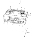
以下、本発明の実施形態について、図面を参照して説明する。図1に示すガスコンロ1は、押し回し式のツマミ11〜13を備えるグリル付きテーブルコンロであるが、グリル無しのテーブルコンロでもよく、キッチンのカウンタトップに設置されるビルトインコンロであってもよい。以下説明では、図中に矢印で示す上下、左右、前後を使用する。   Hereinafter, embodiments of the present invention will be described with reference to the drawings. The gas stove 1 shown in FIG. 1 is a table cooker with a grill provided with push-type knobs 11 to 13, but may be a table cooker without a grill or a built-in stove installed on a countertop of a kitchen. In the following description, the top, bottom, left and right, front and back indicated by arrows in the figure are used.

図1を参照して、ガスコンロ1の外観構造について説明する。ガスコンロ1は、横長の略直方体状の器具2を備える。器具2の天面4右側には右コンロ5、左側には左コンロ6が設けられている。天面4の上面後ろ側には、排気口9が設けられている。排気口9には、スリット状のカバー9Aが設置されている。排気口9は、器具2内に設けられたグリル庫(図示略)内と連通する。器具2前面中央には、グリル庫の前面に設けられたグリル開口(図示略)が設けられている。グリル開口には、グリル扉10が前後方向に移動可能に設けられている。グリル扉10を手前側に引き出すと、グリル扉10の背面下部に連結した受け皿(図示略)及び焼き網を、グリル庫から同時に取り出すことができる。   With reference to FIG. 1, the external structure of the gas stove 1 is demonstrated. The gas stove 1 includes a horizontally long substantially rectangular parallelepiped instrument 2. A right stove 5 is provided on the right side of the top surface 4 of the instrument 2 and a left stove 6 is provided on the left side. An exhaust port 9 is provided behind the top surface 4. The exhaust port 9 is provided with a slit-shaped cover 9A. The exhaust port 9 communicates with the inside of a grill box (not shown) provided in the appliance 2. A grill opening (not shown) provided in the front surface of the grill cabinet is provided in the center of the front surface of the appliance 2. A grill door 10 is provided at the grill opening so as to be movable in the front-rear direction. When the grill door 10 is pulled out to the near side, a tray (not shown) and a grill net connected to the lower rear portion of the grill door 10 can be taken out from the grill cabinet at the same time.

器具2前面において、グリル扉10の右側には、ツマミ11,12が設けられている。グリル扉10の左側には、ツマミ13が設けられている。ツマミ11〜13は押し回し式である。ツマミ11は、右コンロ5のバーナ(以下、単にバーナと呼ぶ)を点火する場合に、正面視反時計回りに約90°押し回しされる。点火後は、時計回りに回動させることによって、火力が大火力から小火力に調節される。ツマミ11を点火前の位置に戻すと、バーナが消火される。なお、詳述しないが、ツマミ12と13の操作方法は、ツマミ11と同じである。ツマミ12は、グリル庫内のグリルバーナ(図示略)を点火する場合に押し回しされ、ツマミ13は、左コンロ6のバーナを点火する為に押し回しされる。   Knobs 11 and 12 are provided on the right side of the grill door 10 on the front surface of the appliance 2. A knob 13 is provided on the left side of the grill door 10. The knobs 11 to 13 are push-push type. The knob 11 is pushed about 90 ° counterclockwise when viewed from the front when the burner of the right stove 5 (hereinafter simply referred to as a burner) is ignited. After ignition, the heating power is adjusted from a large heating power to a small heating power by rotating clockwise. When the knob 11 is returned to the position before ignition, the burner is extinguished. Although not described in detail, the operation method of the knobs 12 and 13 is the same as that of the knob 11. The knob 12 is pushed to ignite a grill burner (not shown) in the grill cabinet, and the knob 13 is pushed to ignite the burner of the left stove 6.

本実施形態では、各種バーナの火力調節の為にツマミ11〜13を回動させる場合において、各種バーナの火力が中火力から小火力に切り替わるときに、軽い引っかかり感(所謂「クリック感」)を、ツマミ11〜13に付与できる。なお、クリック感付与の仕組みについては後述する。   In the present embodiment, when the knobs 11 to 13 are rotated to adjust the heating power of various burners, when the heating power of the various burners is switched from medium heating power to small heating power, a light catching feeling (so-called “click feeling”) is provided. The knobs 11 to 13 can be given. A mechanism for giving a click feeling will be described later.

器具2内部の前側であって、ツマミ11〜13に夫々対応する各位置には、火力調節装置20(図2参照)が夫々設けられている。例えば、右コンロ5に対応する火力調節装置20は、ツマミ11の押し回し操作に応じて、右コンロ5のバーナを点火させるイグナイタ(図示略)を駆動させ、右コンロ5のバーナに供給するガス量を調節する。ツマミ13の左側には、電池ボックス15が設けられている。電池ボックス15は、ガスコンロ1に電源を供給する乾電池(図示略)を格納する。   A thermal power control device 20 (see FIG. 2) is provided at each position on the front side of the appliance 2 and corresponding to the knobs 11 to 13, respectively. For example, the thermal power control device 20 corresponding to the right stove 5 drives an igniter (not shown) that ignites the burner of the right stove 5 in accordance with the pushing operation of the knob 11 and supplies gas to the burner of the right stove 5 Adjust the amount. A battery box 15 is provided on the left side of the knob 13. The battery box 15 stores a dry battery (not shown) that supplies power to the gas stove 1.

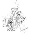
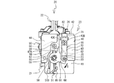
図2〜図5を参照して、火力調節装置20の構造について説明する。各種バーナに対応する火力調節装置20は全て同じ構造であるので、ここでは、右コンロ5のバーナに対応する火力調節装置20の構造を説明する。火力調節装置20は、バルブボディ21、機体22、操作機構23等を備える。バルブボディ21は、火力調節装置20の下部に設けられ、略水平に延びる略円筒状に形成されている。バルブボディ21は、火力調節装置20の本体部であり、操作機構23の後述する操作軸50の回動によって、右コンロ5のバーナに供給するガス量を調節する。機体22は、バルブボディ21の上部に載置され、左右の二つのネジ81(図2〜図4参照)で固定されている。機体22の上部には、略円筒状のガス吐出部37が設けられている。機体22は、バルブボディ21から流れたガスを、ガス吐出部37から右コンロ5のバーナに向けて吐出する。操作機構23は、バルブボディ21の前側部に設けられている。操作機構23は、操作軸50の前端部に嵌合するツマミ11(図3,図4参照)の押し回し操作によって、右コンロ5のバーナ近傍に設けられたイグナイタ(図示略)を駆動させると共に、バルブボディ21内を流れるガス量を調節する。   With reference to FIGS. 2-5, the structure of the thermal-power adjustment apparatus 20 is demonstrated. Since the thermal power control devices 20 corresponding to the various burners all have the same structure, the structure of the thermal power control device 20 corresponding to the burner of the right stove 5 will be described here. The thermal power control device 20 includes a valve body 21, a machine body 22, an operation mechanism 23, and the like. The valve body 21 is provided in the lower part of the thermal power control apparatus 20, and is formed in the substantially cylindrical shape extended substantially horizontal. The valve body 21 is a main body part of the thermal power adjusting device 20, and adjusts the amount of gas supplied to the burner of the right stove 5 by turning an operation shaft 50 described later of the operation mechanism 23. The body 22 is mounted on the upper part of the valve body 21 and is fixed by two screws 81 (see FIGS. 2 to 4). A substantially cylindrical gas discharge part 37 is provided on the upper part of the machine body 22. The machine body 22 discharges the gas flowing from the valve body 21 from the gas discharge unit 37 toward the burner of the right stove 5. The operation mechanism 23 is provided on the front side portion of the valve body 21. The operation mechanism 23 drives an igniter (not shown) provided in the vicinity of the burner of the right stove 5 by pushing and rotating the knob 11 (see FIGS. 3 and 4) fitted to the front end portion of the operation shaft 50. The amount of gas flowing through the valve body 21 is adjusted.

図6を参照し、バルブボディ21と機体22の内部構造について説明する。バルブボディ21は、内部にガス流路を備える。ガス流路は、バルブボディ21の軸方向に延設する。バルブボディ21は、スピンドル25、メイン弁26、安全弁27、ガス入口29、吐出口31、ガス流路32等を備える。スピンドル25は、バルブボディ21のガス流路内に挿入され、該流路に沿って前後方向に進退可能である。スピンドル25の前端部は、後述する操作機構23の操作軸50の後端部と連結する。スピンドル25は、操作軸50の前端部に嵌合するツマミ11の押し回し操作によって、操作軸50と共に後方に押し込まれる。メイン弁26はスピンドル25に固着され、ツマミ11の押し回し操作によって、後述する吐出口31へのガス流路を開閉する。安全弁27はマグネット式であり、点火時のツマミ11の押し回し操作によって後方に押されることでガス流路を開き、右コンロ5のバーナ燃焼時の熱起電力によって開弁状態に保持する。   The internal structure of the valve body 21 and the airframe 22 will be described with reference to FIG. The valve body 21 includes a gas flow path inside. The gas flow path extends in the axial direction of the valve body 21. The valve body 21 includes a spindle 25, a main valve 26, a safety valve 27, a gas inlet 29, a discharge port 31, a gas flow path 32, and the like. The spindle 25 is inserted into the gas flow path of the valve body 21 and can advance and retreat in the front-rear direction along the flow path. A front end portion of the spindle 25 is connected to a rear end portion of an operation shaft 50 of the operation mechanism 23 described later. The spindle 25 is pushed backward together with the operation shaft 50 by a pushing operation of the knob 11 fitted to the front end portion of the operation shaft 50. The main valve 26 is fixed to the spindle 25, and opens and closes a gas flow path to a discharge port 31 to be described later by pushing and turning the knob 11. The safety valve 27 is of a magnet type, and is opened rearward by a thermoelectromotive force during burner combustion of the right stove 5 by being pushed backward by a push operation of the knob 11 at the time of ignition.

ガス入口29は、メイン弁26の近傍に設けられている。ガス入口29は下方に向かって開口し、バルブボディ21内のガス流路内にガスを流入させる。吐出口31は、バルブボディ21内のガス流路の内周面で、且つメイン弁26の下流側に設けられている。吐出口31は、操作軸50と共に回転するスピンドル25との重合面積によって、ガス流路32に向かって吐出するガス量を変化させる。ガス流路32は、吐出口31から上方に延びび、その出口は、バルブボディ21の上部に開口して設けられている。   The gas inlet 29 is provided in the vicinity of the main valve 26. The gas inlet 29 opens downward and allows gas to flow into the gas flow path in the valve body 21. The discharge port 31 is provided on the inner peripheral surface of the gas flow path in the valve body 21 and on the downstream side of the main valve 26. The discharge port 31 changes the amount of gas discharged toward the gas flow path 32 according to the overlapping area with the spindle 25 that rotates together with the operation shaft 50. The gas flow path 32 extends upward from the discharge port 31, and an outlet thereof is provided to open at an upper portion of the valve body 21.

機体22は、ガス流路33〜35を内部に備える。バルブボディ21の上部に設けられたガス流路32の出口は、機体22の下部に設けられたガス流路33の入口と連通する。ガスはガス流路33〜35を順に流れ、ガス吐出部37から右コンロ5のバーナに向かって吐出される。   The machine body 22 includes gas flow paths 33 to 35 therein. The outlet of the gas flow path 32 provided at the upper part of the valve body 21 communicates with the inlet of the gas flow path 33 provided at the lower part of the machine body 22. The gas sequentially flows through the gas flow paths 33 to 35 and is discharged from the gas discharge unit 37 toward the burner of the right stove 5.

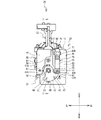
図2〜図6を参照し、操作機構23の構造について説明する。操作機構23は、操作軸50、支持部材40、回動板60、板バネ70、第一バネ係止部材51(図3,図4参照)、第二バネ係止部材52(図3,図4参照)、戻しバネ53(図3,図4参照)、駆動スイッチ55(図4参照)等を備える。   The structure of the operation mechanism 23 will be described with reference to FIGS. The operation mechanism 23 includes an operation shaft 50, a support member 40, a rotating plate 60, a leaf spring 70, a first spring locking member 51 (see FIGS. 3 and 4), and a second spring locking member 52 (FIGS. 3 and 4). 4), a return spring 53 (see FIGS. 3 and 4), a drive switch 55 (see FIG. 4), and the like.

図6を参照し、操作軸50について説明する。操作軸50は、前後方向に延びるように略水平に配置され、その後端側がバルブボディ21の前端部に設けられた開口(図示略)からガス流路内に挿入され、前端側が該開口から前方に突出する(図2,図3参照)。操作軸50の軸方向に直交する断面は、略矩形状に形成されている。操作軸50の前端部は、後述する支持部材40の右前壁部43の左端部と、左前壁部44の右端部に設けられた切欠き部44Aとの間から前方に突出する(図2,図5参照)。操作軸50の前端部には、ツマミ11が嵌合する。操作軸50の後端部は、ガス流路内においてスピンドル25の前端部と連結する。操作軸50は、スピンドル25と共に回動可能で且つ前後方向に進退可能であり、ツマミ11の押し回し操作によって、スピンドル25を後方に押し込む。   The operation shaft 50 will be described with reference to FIG. The operation shaft 50 is disposed substantially horizontally so as to extend in the front-rear direction, and the rear end side is inserted into the gas flow path from an opening (not shown) provided in the front end portion of the valve body 21, and the front end side is forward from the opening. (See FIGS. 2 and 3). A cross section perpendicular to the axial direction of the operation shaft 50 is formed in a substantially rectangular shape. The front end portion of the operation shaft 50 projects forward from between a left end portion of a right front wall portion 43 of the support member 40 described later and a cutout portion 44A provided at the right end portion of the left front wall portion 44 (see FIG. 2, see FIG. The knob 11 is fitted to the front end portion of the operation shaft 50. The rear end portion of the operation shaft 50 is connected to the front end portion of the spindle 25 in the gas flow path. The operation shaft 50 can be rotated together with the spindle 25 and can move back and forth in the front-rear direction, and pushes the spindle 25 rearward by pushing the knob 11.

図2〜図5を参照し、支持部材40の構造について説明する。図2に示すように、支持部材40は、板金を折り曲げることによって側面視下方に開口する略逆U字状に形成され、バルブボディ21の前端部に固定される。支持部材40は、本体部41、上壁部42、右前壁部43、左前壁部44等を備える。本体部41は、正面視縦長の略矩形状に形成され、その略中央には略円形状の開口部(図示略)を備える。本体部41は、バルブボディ21の前端部に、二つのネジ84,85で固定される。本体部41の開口部の内側には、バルブボディ21の前端部から前方に突出する操作軸50が前後方向に進退可能に挿入されている。本体部41の左端部の上下方向略中央の位置には、後方に折り返して延びる支持部41A(図4参照)が設けられている。支持部41Aには、後述する駆動スイッチ55が固定されている。上壁部42は、平面視略矩形状に形成され、本体部41の上端部から前方に折り返して延びる。   The structure of the support member 40 will be described with reference to FIGS. As shown in FIG. 2, the support member 40 is formed in a substantially inverted U shape that opens downward in a side view by bending a sheet metal, and is fixed to the front end portion of the valve body 21. The support member 40 includes a main body portion 41, an upper wall portion 42, a right front wall portion 43, a left front wall portion 44, and the like. The main body 41 is formed in a substantially rectangular shape that is vertically long when viewed from the front, and is provided with a substantially circular opening (not shown) at the approximate center thereof. The main body 41 is fixed to the front end of the valve body 21 with two screws 84 and 85. An operation shaft 50 that protrudes forward from the front end of the valve body 21 is inserted inside the opening of the main body 41 so as to be able to advance and retreat in the front-rear direction. A support portion 41 </ b> A (see FIG. 4) that extends back and extends backward is provided at a substantially central position in the vertical direction of the left end portion of the main body portion 41. A drive switch 55 described later is fixed to the support portion 41A. The upper wall portion 42 is formed in a substantially rectangular shape in plan view, and extends from the upper end portion of the main body portion 41 by folding forward.

図2,図5に示すように、右前壁部43は、上壁部42の前端部における右側から鉛直下方に延び、正面視略矩形状に形成されている。右前壁部43の左下角部には、円弧状の切欠き部43Aが設けられている。切欠き部43Aは、後述する板バネ70の先端部に設けられたピン78との干渉を避ける。右前壁部43の上部には、後述する板バネ70をネジ82で固定する為の固定穴(図示略)が設けられている。その固定穴の上方には、一対の係合穴43B,43Cが左右方向に互いに隙間を空けて設けられている。一対の係合穴43B,43Cには、板バネ70の後述する一対の係止片75(図4,図8参照)が係止する。   As shown in FIGS. 2 and 5, the right front wall portion 43 extends vertically downward from the right side at the front end portion of the upper wall portion 42 and is formed in a substantially rectangular shape in front view. An arcuate cutout 43 </ b> A is provided at the lower left corner of the right front wall 43. The notch 43A avoids interference with a pin 78 provided at the tip of a leaf spring 70 described later. A fixing hole (not shown) for fixing a later-described leaf spring 70 with a screw 82 is provided in the upper portion of the right front wall portion 43. Above the fixing hole, a pair of engagement holes 43B and 43C are provided with a gap in the left-right direction. A pair of locking pieces 75 (see FIG. 4 and FIG. 8), which will be described later, of the leaf spring 70 are locked in the pair of engaging holes 43B and 43C.

左前壁部44は、上壁部42の前端部における左側に設けられ、左前壁部44の位置よりも前方に延びた位置から鉛直下方に延び、正面視略矩形状に形成されている。それ故、左前壁部44は、右前壁部43よりも前方に配置されている。左前壁部44の右下角部には、円弧状の切欠き部44Aが設けられている。切欠き部44Aは、操作軸50の前端部に嵌合するツマミ11(図3参照)との干渉を避ける。   The left front wall portion 44 is provided on the left side of the front end portion of the upper wall portion 42, extends vertically downward from a position extending forward from the position of the left front wall portion 44, and is formed in a substantially rectangular shape in front view. . Therefore, the left front wall portion 44 is disposed in front of the right front wall portion 43. An arcuate notch 44 </ b> A is provided at the lower right corner of the left front wall 44. The notch 44A avoids interference with the knob 11 (see FIG. 3) fitted to the front end of the operation shaft 50.

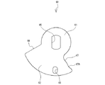
図2,図7を参照し、回動板60の形状について説明する。図2に示すように、回動板60は、バルブボディ21の前端部から前方に突出する操作軸50の前端側に固定されている。回動板60は、前後方向において、右前壁部43と略同一位置に配置されている(図3参照)。回動板60は、操作軸50を中心に操作軸50と一体して回動する。図7に示すように、回動板60は、円盤部61と摺動部62を備え、正面視略扇型状に形成されている。円盤部61は正面視略円形状に形成され、その略中央部には略矩形状の挿入穴65が設けられている。挿入穴65には、操作軸50が挿入される。   The shape of the rotating plate 60 will be described with reference to FIGS. As shown in FIG. 2, the rotating plate 60 is fixed to the front end side of the operation shaft 50 that protrudes forward from the front end portion of the valve body 21. The rotating plate 60 is disposed at substantially the same position as the right front wall portion 43 in the front-rear direction (see FIG. 3). The rotating plate 60 rotates integrally with the operation shaft 50 around the operation shaft 50. As shown in FIG. 7, the rotating plate 60 includes a disk portion 61 and a sliding portion 62 and is formed in a substantially fan shape when viewed from the front. The disc portion 61 is formed in a substantially circular shape when viewed from the front, and a substantially rectangular insertion hole 65 is provided at a substantially central portion thereof. The operation shaft 50 is inserted into the insertion hole 65.

摺動部62は正面視略扇型状に形成され、円盤部61の外周部に沿って設けられている。摺動部62の前面には、回動板60の回動に伴い、後述する板バネ70の先端部に設けられたピン78が摺動する。摺動部62を正面から見た場合に、摺動部62は、挿入穴65を中心とする反時計回り方向における下流側の一端部67と、上流側の他端部68とを備える。一端部67には、円弧状に窪んだ凹部67Aが設けられている。凹部67Aは、摺動部62の前面を摺動するピン78の軌跡上に位置する。さらに、摺動部62におけるピン78の軌跡上であって、且つ凹部67Aの近傍には、係合穴66が設けられている。係合穴66には、摺動部62の前面を摺動するピン78の先端部が落着して係合可能である。係合穴66は、摺動部62前面におけるピン78の軌跡に直交する方向に若干長い略楕円状に形成されている。係合穴66の内縁部は、摺動部62の前面側から背面側に向けて先細りになるようなテーパ状に形成されている(図13参照)。   The sliding part 62 is formed in a substantially fan shape when viewed from the front, and is provided along the outer peripheral part of the disk part 61. As the rotary plate 60 rotates, a pin 78 provided at the tip of a leaf spring 70 described later slides on the front surface of the sliding portion 62. When the sliding portion 62 is viewed from the front, the sliding portion 62 includes a downstream end portion 67 in the counterclockwise direction around the insertion hole 65 and an upstream end portion 68. The one end portion 67 is provided with a concave portion 67A that is recessed in an arc shape. The recess 67A is located on the locus of the pin 78 that slides on the front surface of the sliding portion 62. Furthermore, an engagement hole 66 is provided on the locus of the pin 78 in the sliding portion 62 and in the vicinity of the recess 67A. The front end portion of the pin 78 that slides on the front surface of the sliding portion 62 can be settled and engaged with the engaging hole 66. The engagement hole 66 is formed in a substantially elliptical shape that is slightly longer in the direction perpendicular to the locus of the pin 78 on the front surface of the sliding portion 62. The inner edge part of the engagement hole 66 is formed in a taper shape that tapers from the front side to the back side of the sliding part 62 (see FIG. 13).

回動板60を操作軸50に取り付ける場合、上記の通り、回動板60は正面視略扇型に形成されているので、支持部材40の前方に突出する操作軸50の前端部を、回動板60の挿入穴65に挿入し、そのまま後方に押し込むことによって、左前壁部44の右端部に設けられた切欠き部44Aと干渉することなく、回動板60を右前壁部43と略同一位置に配置できる。それ故、回動板60の取り付け作業は容易である。挿入穴65に操作軸50を挿入した部分は、正面視略C字状の固定ワッシャ58で固定される。これにより、回動板60が操作軸50に固定される。   When the rotation plate 60 is attached to the operation shaft 50, as described above, the rotation plate 60 is formed in a substantially fan shape when viewed from the front, so that the front end portion of the operation shaft 50 protruding forward of the support member 40 is rotated. By inserting it into the insertion hole 65 of the moving plate 60 and pushing it back as it is, the rotating plate 60 is moved to the right front wall portion 43 without interfering with the notch portion 44A provided at the right end portion of the left front wall portion 44. And can be arranged at substantially the same position. Therefore, the mounting operation of the rotating plate 60 is easy. A portion where the operation shaft 50 is inserted into the insertion hole 65 is fixed by a fixing washer 58 having a substantially C shape in front view. Thereby, the rotating plate 60 is fixed to the operation shaft 50.

図2,図8を参照し、板バネ70の構造について説明する。図2に示すように、板バネ70は、支持部材40の右前壁部43の前面に固定される。板バネ70は、上方から下方に延びる細長の板金を折り曲げることによって形成され、右前壁部43の前面にネジ82で固定される部分から回動板60の前面側に延びる。図8に示すように、板バネ70は、上から順に、固定部71、傾斜部72、ピン支持部73、ピン78等を備える。   The structure of the leaf spring 70 will be described with reference to FIGS. As shown in FIG. 2, the leaf spring 70 is fixed to the front surface of the right front wall portion 43 of the support member 40. The leaf spring 70 is formed by bending an elongated sheet metal extending downward from above, and extends from the portion fixed to the front surface of the right front wall portion 43 by a screw 82 to the front surface side of the rotating plate 60. As shown in FIG. 8, the leaf spring 70 includes a fixed portion 71, an inclined portion 72, a pin support portion 73, a pin 78, and the like in order from the top.

固定部71は、支持部材40の右前壁部43の前面に沿って固定される部分であり、上下方向に延びている。固定部71は、正面視縦長の略長方形状に形成され、固定穴(図示略)、一対の係止片75、位置決め部76等を備える。固定穴は、固定部71の略中央に設けられている。該固定穴には、ネジ82が挿入され、支持部材40の右前壁部43に設けられた固定穴(図示略)に締結される。一対の係止片75(図8では片側のみ図示)は、固定部71の左右方向の両端部において、固定穴よりもやや上方の位置から後方に突出し、側面視略半円形状に形成されている。一対の係止片75は、支持部材40の右前壁部43に設けられた一対の係合穴43B,43C(図2参照)に夫々係止する。それ故、本実施形態は、板バネ70の右前壁部43の左右方向における位置ずれを防止できる。位置決め部76は、固定部71の上端部から後方に折り返して突出し、略半円形状に形成されている。位置決め部76は、支持部材40の上壁部42の上面に係止する。それ故、本実施形態は、板バネ70の右前壁部43の上下方向における位置決めを容易にできる。   The fixing portion 71 is a portion that is fixed along the front surface of the right front wall portion 43 of the support member 40 and extends in the vertical direction. The fixing portion 71 is formed in a substantially rectangular shape that is vertically long when viewed from the front, and includes a fixing hole (not shown), a pair of locking pieces 75, a positioning portion 76, and the like. The fixing hole is provided substantially at the center of the fixing portion 71. A screw 82 is inserted into the fixing hole and fastened to a fixing hole (not shown) provided in the right front wall portion 43 of the support member 40. A pair of locking pieces 75 (only one side is shown in FIG. 8) protrudes rearward from a position slightly above the fixing hole at both left and right ends of the fixing portion 71, and is formed in a substantially semicircular shape when viewed from the side. Yes. The pair of locking pieces 75 are respectively locked in a pair of engagement holes 43B and 43C (see FIG. 2) provided in the right front wall portion 43 of the support member 40. Therefore, the present embodiment can prevent the displacement of the right front wall portion 43 of the leaf spring 70 in the left-right direction. The positioning portion 76 protrudes backward from the upper end portion of the fixing portion 71 and is formed in a substantially semicircular shape. The positioning portion 76 is locked to the upper surface of the upper wall portion 42 of the support member 40. Therefore, this embodiment can easily position the right front wall portion 43 of the leaf spring 70 in the vertical direction.

傾斜部72は、固定部71の下端部から前側にやや折れ曲がり、斜め下方に傾斜して延びている。傾斜部72は、正面視縦長の略長方形状に形成されている(図2,図5参照)。ピン支持部73は、傾斜部72の先端部から後ろ側にやや折れ曲がり、斜め下方に延びている。ピン支持部73は、正面視縦長の略長方形状に形成されている(図2,図5参照)。ピン支持部73の先端部は、略円弧状に形成されている。   The inclined portion 72 is bent slightly forward from the lower end of the fixed portion 71 and extends obliquely downward. The inclined portion 72 is formed in a substantially rectangular shape that is vertically long when viewed from the front (see FIGS. 2 and 5). The pin support portion 73 is slightly bent from the front end portion of the inclined portion 72 to the rear side, and extends obliquely downward. The pin support portion 73 is formed in a substantially rectangular shape that is vertically long when viewed from the front (see FIGS. 2 and 5). The distal end portion of the pin support portion 73 is formed in a substantially arc shape.

ピン78は金属製であって、ピン支持部73に支持される。ピン78は、基部78Aと円錐部78Bを同軸上に備える。基部78Aの後端面は、リベット77によって、ピン支持部73の背面に固定される。円錐部78Bは、ピン78の先端部であって、略円錐状に形成されている。板バネ70が支持部材40の右前壁部43の前面に固定された状態では、ピン78は、右前壁部43の切欠き部43Aの近傍に配置される。ピン78の先端部は、操作軸50と共に回動する回動板60の係合穴66の回動軌跡上に位置する。よって、回動板60の回動に伴い、ピン78の先端部は回動板60の前面に乗り上げて摺動し、係合穴66に落着する。回動板60がさらに回動すると、ピン78の先端部は係合穴66から抜け出る。後述するが、ピン78の軸方向は、ピン78の先端部が回動板60の前面と接触する接点における回動板60の前面に垂直な方向に対して、固定部71側から離れる方向に傾斜している(図13参照)。なお、ピン78の軸方向を傾斜させたことによる効果については後述する。   The pin 78 is made of metal and is supported by the pin support portion 73. The pin 78 includes a base portion 78A and a conical portion 78B on the same axis. The rear end surface of the base portion 78 </ b> A is fixed to the back surface of the pin support portion 73 by a rivet 77. The conical portion 78B is a tip portion of the pin 78 and is formed in a substantially conical shape. In a state where the leaf spring 70 is fixed to the front surface of the right front wall portion 43 of the support member 40, the pin 78 is disposed in the vicinity of the notch portion 43 </ b> A of the right front wall portion 43. The tip of the pin 78 is positioned on the rotation locus of the engagement hole 66 of the rotation plate 60 that rotates together with the operation shaft 50. Therefore, as the rotating plate 60 rotates, the tip of the pin 78 rides on the front surface of the rotating plate 60 and slides, and settles in the engagement hole 66. When the rotating plate 60 further rotates, the tip end portion of the pin 78 comes out of the engagement hole 66. As will be described later, the axial direction of the pin 78 is in a direction away from the fixed portion 71 side with respect to a direction perpendicular to the front surface of the rotating plate 60 at a contact point where the tip of the pin 78 contacts the front surface of the rotating plate 60. It is inclined (see FIG. 13). The effect of tilting the axial direction of the pin 78 will be described later.

図3,図4を参照し、その他の部材について説明する。第一バネ係止部材51は、樹脂製の略円筒部材である。第一バネ係止部材51は、操作軸50に装着され、回動板60の背面側に固定される。第一バネ係止部材51は、係止部51Aと付勢部51Bを備える。係止部51Aは略円筒状に形成され、操作軸50に装着される。係止部51Aには、操作軸50に装着される略円筒状の戻しバネ53の軸方向一端側が係止する。付勢部51Bはアーム状に形成され、係止部51Aの左側部から左方に突出する。付勢部51Bの先端部は、後述する駆動スイッチ55の操作子56に対して下方から当接し、上方に付勢する(図4参照)。   Other members will be described with reference to FIGS. The first spring locking member 51 is a substantially cylindrical member made of resin. The first spring locking member 51 is attached to the operation shaft 50 and is fixed to the back side of the rotating plate 60. The first spring locking member 51 includes a locking portion 51A and a biasing portion 51B. The locking portion 51 </ b> A is formed in a substantially cylindrical shape and is attached to the operation shaft 50. One end side in the axial direction of a substantially cylindrical return spring 53 attached to the operation shaft 50 is locked to the locking portion 51A. The urging portion 51B is formed in an arm shape and protrudes leftward from the left side portion of the locking portion 51A. The tip of the urging portion 51B comes into contact with a manipulator 56 of a drive switch 55, which will be described later, and urges upward (see FIG. 4).

第二バネ係止部材52も、第一バネ係止部材51と同様の樹脂製の略円筒部材である。第二バネ係止部材52は、操作軸50に装着され、支持部材40の本体部41の前面側に固定される。第二バネ係止部材52には、戻しバネ53の軸方向他端側が係止する。第一バネ係止部材51と第二バネ係止部材52は、支持部材40の本体部41の前面と、回動板60の背面との間において、前後方向に互いに離間する。戻しバネ53は、第一バネ係止部材51と第二バネ係止部材52の間に圧縮された状態で、操作軸50に装着される。   The second spring locking member 52 is also a substantially cylindrical member made of resin similar to the first spring locking member 51. The second spring locking member 52 is attached to the operation shaft 50 and is fixed to the front side of the main body 41 of the support member 40. The other end side in the axial direction of the return spring 53 is locked to the second spring locking member 52. The first spring locking member 51 and the second spring locking member 52 are separated from each other in the front-rear direction between the front surface of the main body 41 of the support member 40 and the back surface of the rotating plate 60. The return spring 53 is attached to the operation shaft 50 in a compressed state between the first spring locking member 51 and the second spring locking member 52.

図4に示すように、駆動スイッチ55は、支持部材40の本体部41の左端部に設けられた支持部41Aにネジ86で固定される。駆動スイッチ55は、右コンロ5のイグナイタを駆動させる為のスイッチである。駆動スイッチ55の底面側には、アーム状の操作子56が設けられている。操作子56は基端側が軸支され、前方に延びる先端側が上下方向に回動可能である。操作子56の先端部には、第一バネ係止部材51の付勢部51Bが下方から当接する。操作子56の先端部が上方に付勢されると、駆動スイッチ55の底面に設けられたマイクロスイッチ(図示略)が、操作子56によって上方に押し込まれてオフ状態となる。他方、ツマミ11の押し回し操作によって、第一バネ係止部材51が操作軸50と共に回動すると、付勢部51Bが下方に移動するので、操作子56の先端部も下方に移動する。このとき、マイクロスイッチ(図示略)はオン状態となる。   As shown in FIG. 4, the drive switch 55 is fixed to the support portion 41 </ b> A provided at the left end portion of the main body portion 41 of the support member 40 with a screw 86. The drive switch 55 is a switch for driving the igniter of the right stove 5. On the bottom side of the drive switch 55, an arm-shaped operation element 56 is provided. The operation element 56 is pivotally supported at the base end side, and the front end side extending forward is rotatable in the vertical direction. The urging portion 51B of the first spring locking member 51 is in contact with the distal end portion of the operation element 56 from below. When the tip of the operation element 56 is biased upward, a micro switch (not shown) provided on the bottom surface of the drive switch 55 is pushed upward by the operation element 56 to be turned off. On the other hand, when the first spring locking member 51 is rotated together with the operation shaft 50 by the pushing operation of the knob 11, the urging portion 51B moves downward, so that the distal end portion of the operation element 56 also moves downward. At this time, the microswitch (not shown) is turned on.

次に、火力調節装置20の点火操作前(消火時)の状態について説明する。図1に示すように、点火操作前のツマミ11の手で把持する部分は、上下方向を向いた状態である。図4に示すように、操作軸50に装着された第一バネ係止部材51の付勢部51Bは、駆動スイッチ55の操作子56の先端部に対して下方から当接して上方に付勢する。駆動スイッチ55の底面のマイクロスイッチは、上方に押し込まれてオフ状態である。   Next, the state before the ignition operation of the thermal power control device 20 (when extinguishing) will be described. As shown in FIG. 1, the portion gripped by the hand of the knob 11 before the ignition operation is in a state of facing up and down. As shown in FIG. 4, the urging portion 51 </ b> B of the first spring locking member 51 attached to the operation shaft 50 abuts against the distal end portion of the operation element 56 of the drive switch 55 from below and urges upward. To do. The micro switch on the bottom surface of the drive switch 55 is pushed upward and is in an off state.

図2,図5に示すように、回動板60の一端部67は、板バネ70のピン78に対して、時計回り方向に隙間を空けて配置されている。図3,図4に示すように、回動板60は、戻しバネ53によって前方に付勢されているので、支持部材40の右前壁部43と略同一位置に配置される。この状態では、図5に示すように、ピン78は、回動板60の一端部67とは接触していない。それ故、点火操作前の状態では、板バネ70に負荷がかからないので、板バネ70の耐久性を向上できる。   As shown in FIGS. 2 and 5, the one end 67 of the rotating plate 60 is disposed with a gap in the clockwise direction with respect to the pin 78 of the leaf spring 70. As shown in FIGS. 3 and 4, the rotating plate 60 is urged forward by the return spring 53, and thus is disposed at substantially the same position as the right front wall portion 43 of the support member 40. In this state, as shown in FIG. 5, the pin 78 is not in contact with the one end 67 of the rotating plate 60. Therefore, since the load is not applied to the leaf spring 70 before the ignition operation, the durability of the leaf spring 70 can be improved.

さらに、点火操作前の状態では、ツマミ11を押しながら回さないと、操作軸50は、バルブボディ21の内側で回らないようになっているが、回動方向に所定の遊びが設けられている。それ故、点火操作前の状態で、ユーザが誤操作でツマミ11を押さずに回してしまったときでも、操作軸50は所定の遊びの範囲内で回動するだけであるので、板バネ70に負荷がかからない。よって、板バネ70の耐久性をさらに向上できる。   Further, in the state before the ignition operation, unless the knob 11 is pushed and turned, the operation shaft 50 does not turn inside the valve body 21, but a predetermined play is provided in the turning direction. Yes. Therefore, even if the user rotates the knob 11 without pressing the knob 11 by mistake in the state before the ignition operation, the operation shaft 50 only rotates within a predetermined play range. No load is applied. Therefore, the durability of the leaf spring 70 can be further improved.

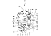
次に、火力調節装置20の点火操作時の動作について説明する。バーナを点火させる為に、ユーザはツマミ11を押しながら反時計回りに約90°回動させる点火操作を行う。ツマミ11と共に、操作軸50も反時計回りに約90°回動する。すると、図6に示すバルブボディ21内のメイン弁26は、吐出口31へのガス流路を開閉する。安全弁27は、後方に押下されてガス流路を開く。操作軸50と共にスピンドル25が回動するので、吐出口31が開き、ガス流路32に向かってガスが流れる。ガス流路32からガス流路33に流れたガスは、ガス流路34,35を流れ、ガス吐出部37から右コンロ5のバーナ本体(図示略)に設けられた混合管(図示略)に向けてガスが吐出される。混合管で一次空気が混合されて生成した混合ガスは、右コンロ5のバーナ本体とバーナヘッド(図示略)との間に形成された複数の炎口(図示略)から噴出する。   Next, the operation | movement at the time of ignition operation of the thermal power control apparatus 20 is demonstrated. In order to ignite the burner, the user performs an ignition operation of rotating about 90 ° counterclockwise while pressing the knob 11. Along with the knob 11, the operation shaft 50 is also rotated about 90 ° counterclockwise. Then, the main valve 26 in the valve body 21 shown in FIG. 6 opens and closes the gas flow path to the discharge port 31. The safety valve 27 is pushed backward to open the gas flow path. Since the spindle 25 rotates together with the operation shaft 50, the discharge port 31 is opened and gas flows toward the gas flow path 32. The gas that has flowed from the gas flow path 32 to the gas flow path 33 flows through the gas flow paths 34 and 35, and from the gas discharge portion 37 to the mixing tube (not shown) provided in the burner body (not shown) of the right stove 5. The gas is discharged toward. The mixed gas produced by mixing the primary air in the mixing tube is ejected from a plurality of flame openings (not shown) formed between the burner body of the right stove 5 and the burner head (not shown).

他方、操作軸50と共に、第一バネ係止部材51も、戻しバネ53の付勢に抗して後方に押し込まれながら反時計回りに約90°回動する。すると、図9に示すように、第一バネ係止部材51の付勢部51Bは下方に移動するので、駆動スイッチ55の操作子56も下方に移動する。駆動スイッチ55はオン状態となり、右コンロ5に設けられたイグナイタが駆動する。イグナイタによって、複数の炎口から噴出されるガスに引火されることによって、右コンロ5の複数の炎口に火炎が形成される。右コンロ5のバーナ燃焼時の熱起電力によって、バルブボディ21内の安全弁27は、開弁状態に保持される。   On the other hand, together with the operating shaft 50, the first spring locking member 51 also rotates about 90 ° counterclockwise while being pushed backward against the biasing force of the return spring 53. Then, as shown in FIG. 9, since the urging portion 51B of the first spring locking member 51 moves downward, the operation element 56 of the drive switch 55 also moves downward. The drive switch 55 is turned on, and the igniter provided on the right stove 5 is driven. The igniter ignites the gas ejected from the plurality of flame openings, thereby forming a flame at the plurality of flame openings of the right stove 5. The safety valve 27 in the valve body 21 is held in the open state by the thermoelectromotive force during burner combustion of the right stove 5.

また、図5に示すように、操作軸50と共に、回動板60も、戻しバネ53の付勢に抗して後方に押し込まれながら反時計回り(図5中P方向)に約90°回動する。このとき、回動板60は、支持部材40の右前壁部43と略同一位置からピン78の円錐部78Bの先端部位置まで押し込まれた状態から反時計回りに回動する。それ故、図9に示すように、ピン78の先端部は、回動板60の一端部67の凹部67Aから前面にスムーズに乗り上げることができる。   Further, as shown in FIG. 5, together with the operation shaft 50, the rotating plate 60 is rotated about 90 ° counterclockwise (P direction in FIG. 5) while being pushed backward against the biasing force of the return spring 53. Move. At this time, the rotation plate 60 rotates counterclockwise from a state where the rotation plate 60 is pushed from substantially the same position as the right front wall portion 43 of the support member 40 to the tip end position of the conical portion 78B of the pin 78. Therefore, as shown in FIG. 9, the tip end portion of the pin 78 can smoothly ride on the front surface from the concave portion 67 </ b> A of the one end portion 67 of the rotating plate 60.

そして、回動板60が反時計回りに回動することに伴い、ピン78の先端部は、回動板60の前面を一端側から他端側に向けて摺動する。上記の通り、回動板60は後方に押し込まれた状態で反時計回りに回動するので、ピン78の先端部が回動板60の前面に接触した状態では、板バネ70は、固定部71を基点として、傾斜部72及びピン支持部73が右前壁部43から前方に離れる方向に若干撓むだけである。それ故、ピン78の先端部が係合穴66に落着して係合するときの衝撃が小さいため、ユーザはクリック感を殆ど感じない。よって、本実施形態は、ツマミ11による点火操作時において、ツマミ11の自然な押し回し操作を実現できる。   As the rotating plate 60 rotates counterclockwise, the tip of the pin 78 slides from the one end side toward the other end side of the front surface of the rotating plate 60. As described above, the rotating plate 60 rotates counterclockwise while being pushed backward, so that the leaf spring 70 is fixed to the fixed portion when the tip of the pin 78 is in contact with the front surface of the rotating plate 60. Starting from 71, the inclined portion 72 and the pin support portion 73 are only slightly bent in a direction away from the right front wall portion 43. Therefore, since the impact when the tip part of the pin 78 settles and engages with the engagement hole 66 is small, the user hardly feels the click feeling. Therefore, this embodiment can realize a natural pushing operation of the knob 11 during the ignition operation by the knob 11.

点火完了後、ユーザはツマミ11から手を離すので、戻しバネ53によって、操作軸50は前方に付勢される。これに伴い、図13に示すように、回動板60も前方に移動するが、ピン78の先端部が回動板60の前面に接触するので、板バネ70は、固定部71のネジ82付近を基点とし、傾斜部72及びピン支持部73が右前壁部43の前面から離間する方向に反るようにして撓む。ピン78の先端部は、板バネ70に生じた弾性復帰力によって、回動板60の前面に押し当てられた状態となる。   After completion of ignition, the user releases his / her hand from the knob 11, so that the operating shaft 50 is urged forward by the return spring 53. Accordingly, as shown in FIG. 13, the rotating plate 60 also moves forward. However, since the tip end portion of the pin 78 contacts the front surface of the rotating plate 60, the leaf spring 70 is fixed to the screw 82 of the fixing portion 71. With the vicinity as a base point, the inclined portion 72 and the pin support portion 73 are bent so as to warp in a direction away from the front surface of the right front wall portion 43. The tip of the pin 78 is pressed against the front surface of the rotating plate 60 by the elastic restoring force generated in the leaf spring 70.

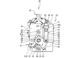
次に、火力調節装置20の火力調節時の動作について説明する。
−大火力から中火力へ−
点火完了後、ピン78と回動板60との相互の位置関係は、図9に示す状態である。点火完了後のバーナは大火力に調節されている。バーナの火力を大火力から中火力に調節する為に、ユーザはツマミ11を時計回りに回動させる。すると、図6に示すように、ツマミ11と共に、操作軸50とスピンドル25は時計回りに回動する。これに伴い、吐出口31とスピンドル25との重合面積が増加するので、吐出口31の開口面積は減少する。それ故、ガス流路32に向かって流れるガス量が減少するので、右コンロ5のバーナは中火力に調節される。
Next, the operation | movement at the time of the thermal power adjustment of the thermal power control apparatus 20 is demonstrated.
-From large thermal power to medium thermal power-
After completion of the ignition, the mutual positional relationship between the pin 78 and the rotating plate 60 is as shown in FIG. The burner after completion of ignition is adjusted to a large heating power. In order to adjust the heating power of the burner from a large heating power to a medium heating power, the user rotates the knob 11 clockwise. Then, as shown in FIG. 6, together with the knob 11, the operation shaft 50 and the spindle 25 rotate clockwise. Along with this, since the overlapping area of the discharge port 31 and the spindle 25 increases, the opening area of the discharge port 31 decreases. Therefore, since the amount of gas flowing toward the gas flow path 32 is reduced, the burner of the right stove 5 is adjusted to medium heating power.

他方、図9,図10,図13に示すように、操作軸50と共に、回動板60も時計回り(図中Q方向)に回動する。これに伴い、ピン78の先端部は、回動板60の前面に押し当てられた状態で、該前面を他端部68側から一端部67側に向けて円弧状に摺動する。中火力におけるピン78と回動板60との相互の位置関係は、図10に示す状態である。   On the other hand, as shown in FIGS. 9, 10, and 13, together with the operation shaft 50, the rotation plate 60 also rotates clockwise (Q direction in the figure). Accordingly, the tip of the pin 78 slides in an arc shape from the other end 68 side toward the one end 67 side while being pressed against the front surface of the rotating plate 60. The mutual positional relationship between the pin 78 and the rotating plate 60 in the medium heating power is as shown in FIG.

−中火力から小火力へ−
バーナの火力を中火力から小火力に調節する為に、ユーザはツマミ11を時計回りにさらに回動させる。これに伴い、図6に示すように、スピンドル25と吐出口31との重合面積がさらに縮小するので、ガス流路32に流れるガス量がさらに減少し、右コンロ5のバーナは小火力に調節される。
-From medium heat to small heat-
In order to adjust the heating power of the burner from medium heating power to small heating power, the user further rotates the knob 11 clockwise. Accordingly, as shown in FIG. 6, since the overlapping area of the spindle 25 and the discharge port 31 is further reduced, the amount of gas flowing through the gas flow path 32 is further reduced, and the burner of the right stove 5 is adjusted to a small heating power. Is done.

他方、図10,図11に示すように、操作軸50と共に、回動板60も時計回り(図中Q方向)にさらに回動する。そして、中火力から小火力に切り替わるときに、それまで回動板60の前面を摺動していたピン78の先端部は、板バネ70の弾性復帰力によって、係合穴66に勢いよく落着する(図11,図14参照)。このときのピン78から回動板60に受ける小さな衝撃が、操作軸50及びツマミ11を介して、ユーザの手にクリック感として付与される。ユーザは、このクリック感を手掛かりにすることによって、中火力から小火力に切り替わる位置を明確に認識できるので、火力調節の操作性を向上できる。また、煮物等の料理において火力を中火力から小火力に絞る際に、火力を絞り過ぎて火が消えることを防止できる。   On the other hand, as shown in FIGS. 10 and 11, together with the operation shaft 50, the rotating plate 60 further rotates clockwise (Q direction in the figure). When the medium heating power is switched to the small heating power, the tip portion of the pin 78 that has been sliding on the front surface of the rotating plate 60 until then is firmly settled in the engagement hole 66 by the elastic return force of the leaf spring 70. (See FIGS. 11 and 14). A small impact received on the rotating plate 60 from the pin 78 at this time is given to the user's hand as a click feeling through the operation shaft 50 and the knob 11. By using this click feeling as a clue, the user can clearly recognize the position at which the medium heating power switches to the small heating power, so that the operability of the heating power adjustment can be improved. In addition, when cooking power such as boiled food is reduced from medium power to small heat power, it is possible to prevent the fire from being extinguished by excessively reducing the heat power.

−小火力から消火へ−
バーナの火力を小火力からさらに弱めて消火する為に、ユーザはツマミ11をクリック感を生じた位置から時計回りにさらに回動させる。これに伴い、図6に示すように、スピンドル25と吐出口31との重合面積がさらに縮小するので、ガス流路32に流れるガス量がさらに減少し、右コンロ5のバーナの火力はさらに弱くなる。
-From small thermal power to fire extinguishing-
In order to extinguish the fire by further reducing the burner's heating power from the small heating power, the user further rotates the knob 11 clockwise from the position where the click feeling is generated. Accordingly, as shown in FIG. 6, since the overlapping area of the spindle 25 and the discharge port 31 is further reduced, the amount of gas flowing through the gas flow path 32 is further reduced, and the heating power of the burner of the right stove 5 is further weakened. Become.

他方、図11,図12に示すように、操作軸50と共に、回動板60も時計回り(図中Q方向)にさらに回動する。このとき、係合穴66に係合するピン78の先端部は、係合穴66の内縁部のテーパ面に沿って一端部67側に抜け出し、回動板60の前面に再び乗り上げる(図12参照)。このとき、板バネ70は、再度、固定部71のネジ82付近を基点とし、傾斜部72及びピン支持部73が右前壁部43の前面から離間する方向に反るようにして撓む。ピン78の先端部は、板バネ70に生じた弾性復帰力によって、回動板60の前面に押し当てられた状態となる。   On the other hand, as shown in FIGS. 11 and 12, together with the operating shaft 50, the rotating plate 60 further rotates clockwise (Q direction in the figure). At this time, the tip of the pin 78 engaged with the engagement hole 66 is pulled out toward the one end 67 along the tapered surface of the inner edge of the engagement hole 66 and rides on the front surface of the rotating plate 60 again (FIG. 12). reference). At this time, the leaf spring 70 is bent again with the vicinity of the screw 82 of the fixing portion 71 as a base point so that the inclined portion 72 and the pin support portion 73 are warped away from the front surface of the right front wall portion 43. The tip of the pin 78 is pressed against the front surface of the rotating plate 60 by the elastic restoring force generated in the leaf spring 70.

そして、ツマミ11を時計回り(図中Q方向)にさらに回動させることによって、吐出口31がスピンドル25によって閉じられると共に、ピン78の先端部が回動板60の前面を一端部67の凹部67Aから反時計回り方向に外れる。このとき、回動板60の前面にかけられていた板バネ70の付勢力が一気に無くなるので、回動板60及び操作軸50は、戻しバネ53によって前方に押し出される。ピン78の先端部は、回動板60の前面から外れて、右前壁部43の切欠き部43Aと、回動板60の一端部67の凹部67Aとの隙間に配置される。操作軸50と共に、スピンドル25も前方に移動するので、メイン弁26は、吐出口31へのガス流路を閉じ、安全弁27も前方に移動してガス流路を閉じる。このようにして、右コンロ5が消火され、図6の状態に戻る。なお、小火力から大火力に調節する場合は、上記動作の流れと逆の流れとなるので、説明を省略する。   Then, by further rotating the knob 11 in the clockwise direction (Q direction in the figure), the discharge port 31 is closed by the spindle 25, and the tip of the pin 78 makes the front surface of the rotating plate 60 the recess of the one end 67. Deviates counterclockwise from 67A. At this time, since the urging force of the leaf spring 70 applied to the front surface of the rotating plate 60 disappears all at once, the rotating plate 60 and the operation shaft 50 are pushed forward by the return spring 53. The tip of the pin 78 is disengaged from the front surface of the rotating plate 60 and is disposed in the gap between the notch 43A of the right front wall 43 and the recess 67A of the one end 67 of the rotating plate 60. Since the spindle 25 also moves forward together with the operation shaft 50, the main valve 26 closes the gas flow path to the discharge port 31, and the safety valve 27 also moves forward to close the gas flow path. In this way, the right stove 5 is extinguished and the state returns to the state of FIG. In addition, when adjusting from a small thermal power to a large thermal power, since it becomes the reverse flow of the said operation | movement, description is abbreviate | omitted.

このようにして、本実施形態のガスコンロ1は、各種バーナの火力を調節する場合において、中火力から小火力に切り替わる所定の火力位置で、ツマミ11にクリック感を付与できる。これにより、ユーザはクリック感を手掛かりに、バーナの火力を細かく調節できるので、火力調節の操作性を向上できる。そして、本実施形態は、回動板60と、ピン78を備えた板バネ70とを用いるだけの簡単な構造であるので、従来のガスコンロの構造に簡単に取り付けることができる。さらに、簡単な構造であるので、部品交換、修理等のメンテナンスが容易で、部品コストも安価に抑えられる。   Thus, the gas stove 1 of this embodiment can provide a click feeling to the knob 11 at a predetermined thermal power position where the medium thermal power is switched to the small thermal power when adjusting the thermal power of various burners. Thereby, the user can finely adjust the heating power of the burner with the click feeling as a clue, so that the operability of the thermal power adjustment can be improved. And since this embodiment is a simple structure only using the rotation board 60 and the leaf | plate spring 70 provided with the pin 78, it can be easily attached to the structure of the conventional gas stove. Furthermore, since the structure is simple, maintenance such as parts replacement and repair is easy, and the part cost can be kept low.

図13〜図15を参照し、回動板60の前面に対して、ピン78の軸方向を傾斜させたことによる効果を説明する。図15に示す板バネ170は、ピン78の軸方向を、回動板60の前面に対して垂直になるように調節したものである。それ以外は、図8に示す板バネ70と同じ構造であるので、同一の符号を付して説明する。このような板バネ170を用いて、ピン78の先端部を回動板60の前面に接触させた場合、板バネ70と同様に、板バネ170は、固定部71のネジ82付近を基点とし、傾斜部72及びピン支持部73が右前壁部43の前面から離間する方向に反るようにして撓む。このような状態で、ツマミ11を時計回り(大火力から小火力へ:図15中Q方向)に回動させた場合と、反時計回り(小火力から大火力へ:図15中R方向)に回動させた場合とでは、ピン78が回動板60の係合穴66を通過するときに生じるクリック感の強さに差異が生じてしまう。   With reference to FIGS. 13 to 15, the effect of tilting the axial direction of the pin 78 with respect to the front surface of the rotating plate 60 will be described. The leaf spring 170 shown in FIG. 15 is obtained by adjusting the axial direction of the pin 78 so as to be perpendicular to the front surface of the rotating plate 60. The rest of the structure is the same as that of the leaf spring 70 shown in FIG. When such a leaf spring 170 is used to bring the tip of the pin 78 into contact with the front surface of the rotating plate 60, the leaf spring 170 is based on the vicinity of the screw 82 of the fixing portion 71 as in the leaf spring 70. The inclined portion 72 and the pin support portion 73 are bent so as to warp in a direction away from the front surface of the right front wall portion 43. In this state, when the knob 11 is rotated clockwise (from a large heating power to a small heating power: Q direction in FIG. 15), and counterclockwise (from a small heating power to a large heating power: R direction in FIG. 15). In the case where the pin 78 is rotated, the difference in the strength of the click feeling that occurs when the pin 78 passes through the engagement hole 66 of the rotation plate 60 occurs.

例えば、図16に示すように、ピン78の先端部が回動板60の係合穴66に係合した状態から、ツマミ11を時計回りに回動させた場合(大火力から小火力へ)、回動板60は図16中Q方向に回動する。ピン78の先端部は、係合穴66の内縁部によって固定部71側とは反対方向(図16中S方向)に引っ張られるので、板バネ170は、固定部71側とは反対方向に引っ張られる状態となる。そして、係合穴66の内縁部はテーパ面になっているので、ピン78の先端部は、そのテーパ面に沿って摺動することによって一端部67側にスムーズに抜け出る。このとき、板バネ170に大きな応力がかからないので、ピン78の先端部は係合穴66から比較的抜け易いといえる。よって、ピン78の先端部が係合穴66を通過するときに生じるクリック感は小さくなる。   For example, as shown in FIG. 16, when the knob 11 is rotated clockwise from the state in which the tip end portion of the pin 78 is engaged with the engagement hole 66 of the rotation plate 60 (from large thermal power to small thermal power). The rotating plate 60 rotates in the Q direction in FIG. The tip end of the pin 78 is pulled in the opposite direction (S direction in FIG. 16) to the fixed portion 71 side by the inner edge portion of the engagement hole 66, so that the leaf spring 170 is pulled in the opposite direction to the fixed portion 71 side. It will be in the state to be. And since the inner edge part of the engagement hole 66 is a taper surface, the front-end | tip part of the pin 78 slips out smoothly to the one end part 67 side by sliding along the taper surface. At this time, since a large stress is not applied to the leaf spring 170, it can be said that the tip of the pin 78 is relatively easy to come out of the engagement hole 66. Therefore, the click feeling generated when the tip of the pin 78 passes through the engagement hole 66 is reduced.

これに対し、ピン78の先端部が回動板60の係合穴66に係合した状態から、ツマミ11を反時計回りに回動させた場合(小火力から大火力へ)、回動板60は図16中R方向に回動する。ピン78の先端部は、係合穴66の内縁部によって固定部71側(図16中T方向)に押し込まれるが、板バネ170は、固定部71がネジ82で固定されているので、傾斜部72及びピン支持部73が、ピン78とネジ82との間で圧縮された状態となる。この場合、板バネ170に大きな応力がかかるので、ピン78は係合穴66から比較的抜け難いといえる。よって、ピン78の先端部が係合穴66を通過するときに生じるクリック感は大きくなる。このように、回動板60の回動方向の違いによって、ピン78の係合穴66からの抜け易さが異なるので、ピン78の先端部が係合穴66を通過するときに生じるクリック感に差異を生じてしまう。   On the other hand, when the knob 11 is rotated counterclockwise from the state in which the tip end portion of the pin 78 is engaged with the engagement hole 66 of the rotating plate 60 (from small heating power to large heating power), the rotating plate 60 rotates in the R direction in FIG. The tip of the pin 78 is pushed toward the fixing portion 71 (T direction in FIG. 16) by the inner edge of the engagement hole 66, but the leaf spring 170 is inclined because the fixing portion 71 is fixed by a screw 82. The part 72 and the pin support part 73 are compressed between the pin 78 and the screw 82. In this case, since a large stress is applied to the leaf spring 170, it can be said that the pin 78 is relatively difficult to be removed from the engagement hole 66. Therefore, the click feeling generated when the tip of the pin 78 passes through the engagement hole 66 is increased. As described above, the ease of removal of the pin 78 from the engagement hole 66 differs depending on the rotation direction of the rotation plate 60, so that the click feeling generated when the tip of the pin 78 passes through the engagement hole 66. Make a difference.

そこで、本実施形態は、回動板60を何れの方向に回動させた場合でも、ピン78が係合穴66を通過するときに生じるクリック感を揃える為に、以下の特徴を備えている。図13に示すように、ピン78の先端部は、図13中に示す接点Aにおいて、回動板60の前面と接触する。その接点Aにおける回動板60が操作軸50と共に反時計回りに回動する方向は、図13中に示すR方向である。R方向は、板バネ70の支持部材40の右前壁部43の前面に固定される固定部71からピン支持部73の先端部に向かう方向に対して略反対方向である。   Therefore, the present embodiment has the following features in order to align the click feeling that occurs when the pin 78 passes through the engagement hole 66 regardless of the direction in which the rotation plate 60 is rotated. . As shown in FIG. 13, the tip of the pin 78 contacts the front surface of the rotating plate 60 at the contact point A shown in FIG. 13. The direction in which the rotating plate 60 at the contact A rotates counterclockwise together with the operation shaft 50 is the R direction shown in FIG. The R direction is substantially opposite to the direction from the fixed portion 71 fixed to the front surface of the right front wall portion 43 of the support member 40 of the leaf spring 70 toward the tip portion of the pin support portion 73.

このような構成において、ピン78の軸方向を、接点Aにおける回動板60の前面に垂直な方向(図13中K方向)に対して、固定部71から離れる側に傾斜させている。これにより、図14に示すように、ピン78の先端部が係合穴66に係合した状態において、係合穴66の一端部67側のテーパ面に対して、ピン78の円錐部78Bのテーパ面が対向するようになる。これにより、ツマミ11を時計回りに回動させ、回動板60を図14中Q方向に回動させた場合に、ピン78の円錐部78Bのテーパ面が、係合穴66の一端部67側のテーパ面に強く引っ掛かるようになるので、板バネ170に比べて、若干抜け難くすることができる。   In such a configuration, the axial direction of the pin 78 is inclined to the side away from the fixed portion 71 with respect to the direction (K direction in FIG. 13) perpendicular to the front surface of the rotating plate 60 at the contact A. Accordingly, as shown in FIG. 14, the conical portion 78 </ b> B of the pin 78 with respect to the tapered surface on the one end 67 side of the engagement hole 66 in a state where the tip end portion of the pin 78 is engaged with the engagement hole 66. The tapered surfaces come to face each other. Thereby, when the knob 11 is rotated clockwise and the rotation plate 60 is rotated in the Q direction in FIG. 14, the tapered surface of the conical portion 78 </ b> B of the pin 78 is at one end 67 of the engagement hole 66. Since it is strongly hooked to the taper surface on the side, it can be made somewhat difficult to come out compared to the leaf spring 170.

他方、係合穴66の他端部68側のテーパ面に対して、ピン78の円錐部78Bのテーパ面がより傾斜して配置されるようになる。これにより、ツマミ11を反時計回りに回動させ、回動板60を図14中R方向に回動させた場合、ピン78の円錐部78Bのテーパ面が係合穴66の前面側の角部66Aを滑るように他端部68側に抜け出るようになるので、板バネ170に比べて、若干抜け易くすることができる。これにより、ツマミ11を大火力から小火力に回動させた場合と、小火力から大火力に回動させた場合とにおいて、クリック感を揃えることができるので、ツマミ11のより自然な回動操作を提供できる。   On the other hand, the tapered surface of the conical portion 78B of the pin 78 is arranged to be more inclined with respect to the tapered surface of the engagement hole 66 on the other end portion 68 side. Thereby, when the knob 11 is rotated counterclockwise and the rotating plate 60 is rotated in the R direction in FIG. 14, the tapered surface of the conical portion 78 </ b> B of the pin 78 is a corner on the front side of the engagement hole 66. Since it comes out to the other end portion 68 side so as to slide on the portion 66A, it can be slightly removed as compared with the leaf spring 170. Thereby, since the click feeling can be made uniform when the knob 11 is rotated from a large heating power to a small heating power and when the knob 11 is rotated from a small heating power to a large heating power, the knob 11 can be rotated more naturally. Can provide operation.

以上説明したように、本実施形態のガスコンロ1は、右コンロ5のバーナの火力調節を行う火力調節装置20を備える。火力調節装置20は、操作軸50、回動板60、板バネ70を備える。操作軸50は、火力調節装置20の本体部であるバルブボディ21に回動可能に軸支され、火力調節の為に回転操作される。回動板60は、操作軸50と一体して設けられ、操作軸50を中心に回動する。回動板60の前面には、係合穴66が設けられている。板バネ70は、バルブボディ21に支持部材40を介して固定され、支持部材40の右前壁部43の前面に固定される固定部71から回動板60の前面側に延びる。板バネ70の先端部には、ピン78が設けられている。ピン78は、回動板60の回動に伴って回動する係合穴66の回動軌跡上に配置されている。板バネ70は、ピン78が設けられた先端部を回動板60の前面側に付勢する。回動板60が所定の火力に切り替わる位置に回動したとき、ピン78は、係合穴66に落着して係合する。係合穴66にピン78が係合する際に生じる衝撃は、操作軸50を介してユーザの手にクリック感として伝わる。ユーザはこのクリック感を手掛かりにすることで、火力調節の目安にできるので、火力調節の操作性を向上できる。また、操作軸50に回動板60を設けて、ピン78を固定した板バネ70を取り付けるだけの簡単な構造であるので、取り付け、部品交換、修理等が容易で、部品コストも安価に抑えられる。   As described above, the gas stove 1 of the present embodiment includes the thermal power adjusting device 20 that adjusts the thermal power of the burner of the right stove 5. The thermal power adjusting device 20 includes an operation shaft 50, a rotating plate 60, and a leaf spring 70. The operation shaft 50 is pivotally supported by the valve body 21 which is a main body portion of the thermal power adjusting device 20, and is rotated for adjusting the thermal power. The rotation plate 60 is provided integrally with the operation shaft 50 and rotates around the operation shaft 50. An engagement hole 66 is provided on the front surface of the rotating plate 60. The leaf spring 70 is fixed to the valve body 21 via the support member 40, and extends from the fixing portion 71 fixed to the front surface of the right front wall portion 43 of the support member 40 to the front surface side of the rotating plate 60. A pin 78 is provided at the tip of the leaf spring 70. The pin 78 is disposed on the rotation locus of the engagement hole 66 that rotates as the rotation plate 60 rotates. The leaf spring 70 urges the front end portion on which the pin 78 is provided to the front surface side of the rotating plate 60. When the rotation plate 60 is rotated to a position where the rotation plate 60 is switched to a predetermined heating power, the pin 78 is settled in the engagement hole 66 and engaged. An impact generated when the pin 78 is engaged with the engagement hole 66 is transmitted to the user's hand as a click feeling through the operation shaft 50. By using this click feeling as a clue, the user can use it as a guide for adjusting the thermal power, so that the operability of the thermal power adjustment can be improved. Further, since the rotation plate 60 is provided on the operation shaft 50 and the leaf spring 70 with the pin 78 fixed is simply attached, the attachment, parts replacement, repair, etc. are easy, and the parts cost is kept low. It is done.

また、上記実施形態の火力調節装置20は、操作軸50に設けられたツマミ11を操作軸50の軸方向に押し込みながら、反時計回りに回動させる点火操作を行うことで、バーナへのガス流路を開く機能を備える。反時計回りは、火力を小火力から大火力に調節するときの方向である。また、回動板60は、操作軸50を中心とする略扇形状に形成されている。さらに、点火操作前及びバーナ消火時において、ピン78は、回動板60の外周方向の両端部のうち、操作軸50と共に回動する反時計回り方向の下流側の一端部67から離脱し、且つ一端部67から一方向側に隙間を空けて配置されている。点火操作時において、ピン78は、一端部67側から前面に乗り上げ、一端部67とは反対側の上流側の他端部68側に向けて摺動する。このように、ツマミ11の点火操作前では、板バネ70の先端部に設けられたピン78は、回動板60から離脱して、隙間を空けて配置されている。これにより、点火操作前では、板バネ70に負荷がかからないようにできるので、板バネ70の耐久性を向上できる。   Further, the thermal power control apparatus 20 of the above embodiment performs an ignition operation of rotating the knob 11 provided on the operation shaft 50 in the counterclockwise direction while pushing the knob 11 in the axial direction of the operation shaft 50, thereby providing gas to the burner. A function to open the flow path is provided. The counterclockwise direction is a direction for adjusting the thermal power from a small thermal power to a large thermal power. The rotating plate 60 is formed in a substantially fan shape with the operation shaft 50 as the center. Further, before the ignition operation and at the time of extinguishing the burner, the pin 78 is disengaged from the one end 67 on the downstream side in the counterclockwise direction rotating together with the operation shaft 50 among the both ends in the outer peripheral direction of the rotating plate 60, And it arrange | positions with the clearance gap from the one end part 67 to one direction side. During the ignition operation, the pin 78 rides on the front surface from the one end portion 67 side and slides toward the other end portion 68 side on the upstream side opposite to the one end portion 67. As described above, before the ignition operation of the knob 11, the pin 78 provided at the distal end portion of the leaf spring 70 is separated from the rotating plate 60 and disposed with a gap. Thereby, it is possible to prevent the leaf spring 70 from being loaded before the ignition operation, so that the durability of the leaf spring 70 can be improved.

また、上記実施形態では、点火操作前及記消火時の操作軸50に対して、操作軸50の回転方向に遊びを設けているので、点火操作前に、ユーザの誤操作でツマミ11が押されずに回された場合、操作軸50は遊びの範囲内で回転するだけであるので、仮に板バネ70に回動板60が接触した場合あっても、板バネ70に負荷がかからない。これにより、板バネ70の耐久性を向上できる。   Further, in the above embodiment, since play is provided in the rotation direction of the operation shaft 50 with respect to the operation shaft 50 before the ignition operation and during the fire extinguishing operation, the knob 11 is not pushed by an erroneous operation of the user before the ignition operation. When the rotary shaft 60 is rotated, the operating shaft 50 only rotates within the range of play. Therefore, even if the rotating plate 60 contacts the leaf spring 70, no load is applied to the leaf spring 70. Thereby, durability of the leaf | plate spring 70 can be improved.

また、上記実施形態は、ツマミ11を押し込む方向とは反対側に操作軸50を付勢する戻しバネ53を備える。さらに、点火操作時において、回動板60は、操作軸50と共に押し込まれた状態で回動する。これにより、点火操作時にツマミ11を押し回した際には、ピン78が回動板60の前面から離れる方向に移動するので、係合穴66を通過するときに得られるクリック感を緩和できる。よって、ユーザは点火操作時において、ツマミ11を違和感が無く操作できる。   Moreover, the said embodiment is provided with the return spring 53 which urges | biases the operating shaft 50 on the opposite side to the direction which pushes the knob 11. FIG. Further, during the ignition operation, the rotating plate 60 rotates while being pushed together with the operation shaft 50. Thereby, when the knob 11 is pushed around during the ignition operation, the pin 78 moves in a direction away from the front surface of the rotary plate 60, so that the click feeling obtained when passing through the engagement hole 66 can be alleviated. Therefore, the user can operate the knob 11 without feeling uncomfortable during the ignition operation.

また、上記実施形態では、ピン78の先端部が回動板60の前面と接触する接点における回動板60が操作軸50と共に回動する反時計回り方向(図13中R方向)は、板バネ70の支持部材40に固定される固定部71から先端部に向かう方向に対して略反対方向である。そして、ピン78の軸方向は、ピン78の先端部との接点における回動板60の前面に垂直な方向(図13中K方向)に対して、固定部71側から離れる方向に傾斜している。これにより、回動板60が操作軸50と共に時計回りと反時計回りに回動する場合のピン78の係合穴66からの抜け易さを揃えることができる。よって、操作軸50を時計回り及び反時計回りに回転させたときに生じるクリック感を揃えることができる。   In the above embodiment, the counterclockwise direction (R direction in FIG. 13) in which the rotating plate 60 rotates with the operation shaft 50 at the contact point where the tip of the pin 78 contacts the front surface of the rotating plate 60 is the plate The direction is substantially opposite to the direction from the fixed portion 71 fixed to the support member 40 of the spring 70 toward the tip portion. And the axial direction of the pin 78 inclines in the direction away from the fixed part 71 side with respect to the direction (K direction in FIG. 13) perpendicular to the front surface of the rotating plate 60 at the contact point with the tip of the pin 78. Yes. Thereby, it is possible to make it easy to remove the pin 78 from the engagement hole 66 when the rotating plate 60 rotates clockwise and counterclockwise together with the operation shaft 50. Therefore, it is possible to align the click feeling generated when the operation shaft 50 is rotated clockwise and counterclockwise.

また、上記実施形態では、回動板60に設けられる係合穴66の内縁部は、テーパ状に形成されている。これにより、ピン78の先端部は、係合穴66にスムーズに係合して離脱するので、スムーズなクリック感を得ることができる。   Moreover, in the said embodiment, the inner edge part of the engagement hole 66 provided in the rotation board 60 is formed in the taper shape. Thereby, the tip end portion of the pin 78 is smoothly engaged with and disengaged from the engagement hole 66, so that a smooth click feeling can be obtained.

また、上記実施形態では、中火力と小火力の間の火力位置で、クリック感が付与されるようになっているので、例えば、料理において火力を中火力から小火力に絞る際に、火力を絞り過ぎて火が消えることを防止できる。   Further, in the above embodiment, a click feeling is given at a thermal power position between a medium thermal power and a small thermal power.For example, when a thermal power is reduced from a medium thermal power to a small thermal power in cooking, the thermal power is reduced. It can prevent the fire from extinguishing too much.

なお、本発明は上記実施形態に限定されるものではなく、種々の変更が可能である。上記実施形態では、中火力と小火力の間の火力位置でクリック感が付与されるように、回動板60の係合穴66の位置を決めているが、その他の火力位置でクリック感が付与されるようにしてもよい。例えば、大火力と中火力の間の火力位置でクリック感が付与されるようにしてもよい。また、上記実施形態では、回動板60に一つの係合穴66を設けているが、複数個設けることによって、複数の火力位置でクリック感が付与されるようにしてもよい。   In addition, this invention is not limited to the said embodiment, A various change is possible. In the above embodiment, the position of the engagement hole 66 of the rotating plate 60 is determined so that the click feeling is given at the heating power position between the medium heating power and the small heating power, but the clicking feeling is at other heating power positions. It may be given. For example, a click feeling may be given at a thermal power position between large thermal power and medium thermal power. Moreover, in the said embodiment, although the one engagement hole 66 is provided in the rotation board 60, you may make it provide a click feeling in a several thermal power position by providing two or more.

また、上記実施形態の回動板60には、板厚方向に貫通する係合穴66を設けているが、貫通していなくてもよく、前面側から背面側に窪んで凹状に形成された溝部であってもよい。また、係合穴66の代わりに、前面側に突出する凸部を設けてもよい。このようなものでも、クリック感を付与できる。   In addition, the rotation plate 60 of the above embodiment is provided with the engagement hole 66 penetrating in the plate thickness direction, but it may not be penetrated, and it is formed in a concave shape recessed from the front side to the back side. It may be a groove. Further, instead of the engagement hole 66, a convex portion protruding to the front side may be provided. Even such a thing can provide a click feeling.

また、上記実施形態において、点火操作時、及び火力調節時等のツマミ11の回動方向は、逆方向であってもよい。例えば、点火操作時は、ツマミ11を時計回りに押し回しするようにしてもよく、大火力から小火力に調節する場合は、ツマミ11を反時計回りに回動するようにしてもよい。   Moreover, in the said embodiment, the rotation direction of the knob 11 at the time of ignition operation, the time of thermal power adjustment, etc. may be a reverse direction. For example, when the ignition operation is performed, the knob 11 may be pushed and rotated clockwise, and when adjusting from a large heating power to a small heating power, the knob 11 may be rotated counterclockwise.

また、バルブボディ21内の構造は、上記実施形態に限定されるものではない。また、回動板60の形状は、上記実施形態のような略扇型形状以外に、例えば、円形でもよく、中心角が鈍角の略扇型であってもよい。   Further, the structure in the valve body 21 is not limited to the above embodiment. Further, the shape of the rotating plate 60 may be, for example, a circle or a substantially fan shape with an obtuse central angle other than the substantially fan shape as in the above embodiment.

また、回動板60に対する板バネ70の配置方向について、上記実施形態では、ネジ82で固定される固定部71から下方に延びるようにして配置されているが、例えば、ピン78の先端部が回動板60の前面と接触する接点において、横方向、又は斜め方向に配置するようにしてもよい。   Further, in the above-described embodiment, the leaf spring 70 is disposed with respect to the rotating plate 60 so as to extend downward from the fixing portion 71 fixed with the screw 82. You may make it arrange | position in the horizontal direction or the diagonal direction in the contact which contacts the front surface of the rotation board 60. FIG.

また、上記実施形態では、ツマミ11を押し込む方向とは反対側に操作軸50を付勢する付勢手段として、戻しバネ53を用いているが、バネ以外の弾性部材を用いてもよく、板バネや、ゴム、樹脂等の弾性部材を用いてもよい。また、戻しバネ53は、操作軸50に装着しなくてもよい。   In the above embodiment, the return spring 53 is used as the biasing means for biasing the operation shaft 50 in the direction opposite to the direction in which the knob 11 is pushed. However, an elastic member other than the spring may be used. An elastic member such as a spring, rubber, or resin may be used. Further, the return spring 53 may not be attached to the operation shaft 50.

1 ガスコンロ
5 右コンロ
11 ツマミ
20 火力調節装置
21 バルブボディ
40 支持部材
50 操作軸
53 戻しバネ
60 回動板
66 係合穴
67 一端部
68 他端部
70 板バネ
71 固定部
78 ピン
A 接点
DESCRIPTION OF SYMBOLS 1 Gas stove 5 Right stove 11 Knob 20 Thermal power control device 21 Valve body 40 Support member 50 Operation shaft 53 Return spring 60 Rotating plate 66 Engagement hole 67 One end portion 68 Other end portion 70 Plate spring 71 Fixing portion 78 Pin A Contact

Claims (7)

バーナの火力調節を行う火力調節装置を備えたガスコンロにおいて、
前記火力調節装置は、
本体部と、
前記本体部に回動可能に軸支され、前記火力調節の為に回転操作される操作軸と、
前記操作軸と一体して設けられ、前記操作軸を中心に回動する回動板と、
前記回動板の片面に設けられた溝部又は穴部と、
前記本体部に固定され、前記本体部に固定される固定部から前記回動板の前記片面側に延びる板バネと、
前記板バネの先端部に設けられると共に、前記回動板の回動に伴って回動する前記溝部又は前記穴部の回動軌跡上に配置され、前記回動板が所定の火力位置に回動したときに、前記溝部又は前記穴部に係合可能なピンと
を備え、
前記板バネは、前記ピンが設けられた前記先端部を前記回動板の前記片面側に付勢すること
を特徴とするガスコンロ。
In a gas stove equipped with a thermal power control device that controls the thermal power of the burner,
The thermal power control device
The main body,
An operation shaft that is pivotally supported by the main body and is rotated for adjusting the heating power,
A rotating plate provided integrally with the operating shaft and rotating around the operating shaft;
A groove or a hole provided on one side of the rotating plate;
A leaf spring fixed to the main body portion and extending from the fixed portion fixed to the main body portion to the one side of the rotating plate;
It is provided at the tip of the leaf spring and is arranged on a turning locus of the groove or the hole that rotates as the rotating plate rotates, and the rotating plate rotates to a predetermined thermal power position. A pin that is engageable with the groove or the hole when moved.
The gas stove, wherein the leaf spring urges the tip portion provided with the pin to the one surface side of the rotating plate.
前記火力調節装置は、
前記操作軸に設けられたツマミを前記操作軸の軸方向に押し込みながら、火力を小火力から大火力に調節するときの方向である一方向に回転させる点火操作を行うことで、前記バーナへのガス流路を開く機能を備え、
前記回動板は、前記操作軸を中心とする略扇形状に形成され、
点火操作前及び前記バーナの消火時において、前記ピンは、前記回動板の外周方向の両端部のうち、前記操作軸と共に回動する前記一方向の下流側の一端部から離脱し、且つ前記下流側の一端部から前記一方向側に隙間を空けて配置され、
点火操作時において、前記ピンは、前記一方向に回動する前記回動板の前記下流側の一端部側から前記片面上に乗り上げ、前記下流側の一端部とは反対側の上流側の他端部側に向けて摺動すること
を特徴とする請求項1に記載のガスコンロ。
The thermal power control device
By pressing the knob provided on the operation shaft in the axial direction of the operation shaft, by performing an ignition operation that rotates in one direction, which is a direction when adjusting the heating power from a small heating power to a large heating power, With the function to open the gas flow path,
The rotating plate is formed in a substantially fan shape centered on the operation shaft,
Before the ignition operation and when the burner is extinguished, the pin is disengaged from one end on the downstream side in the one direction rotating with the operation shaft among both ends in the outer peripheral direction of the rotating plate, and It is arranged with a gap from the one end on the downstream side to the one direction side,
During the ignition operation, the pin rides on the one surface from the downstream end portion of the rotating plate that rotates in the one direction, and the other upstream side opposite to the downstream end portion. The gas stove according to claim 1, wherein the gas stove slides toward the end side.
点火操作前及び消火時の前記操作軸に対して、前記操作軸の回転方向に遊びを設けたこと
を特徴とする請求項2に記載のガスコンロ。
The gas stove according to claim 2, wherein play is provided in a rotation direction of the operation shaft with respect to the operation shaft before ignition operation and at the time of fire extinguishing.
前記ツマミを押し込む方向とは反対側に前記操作軸を付勢する付勢手段を備え、
点火操作時において、前記回動板は、前記操作軸と共に押し込まれた状態で回動すること
を特徴とする請求項2又は3に記載のガスコンロ。
Urging means for urging the operating shaft on the opposite side to the direction in which the knob is pushed in;
4. The gas stove according to claim 2, wherein during the ignition operation, the rotating plate rotates while being pushed together with the operation shaft.
前記ピンの先端部が前記回動板の前記片面と接触する接点における前記回動板が前記操作軸と共に回動する前記一方向は、前記板バネの前記本体部に固定される前記固定部から前記先端部に向かう方向に対して略反対方向であって、
前記ピンの軸方向は、前記接点における前記回動板の前記片面に垂直な方向に対して、前記固定部側から離れる方向に傾斜していること
を特徴とする請求項2から4の何れか一つに記載のガスコンロ。
The one direction in which the rotating plate rotates together with the operation shaft at a contact point where the tip end portion of the pin contacts the one surface of the rotating plate is from the fixed portion fixed to the main body portion of the plate spring. A direction substantially opposite to the direction toward the tip,
The axial direction of the pin is inclined in a direction away from the fixed portion side with respect to a direction perpendicular to the one surface of the rotating plate at the contact point. The gas stove according to one.
前記溝部又は前記穴部の内縁部は、テーパ状に形成されていることを特徴とする請求項1から5の何れか一つに記載のガスコンロ。   The gas stove according to any one of claims 1 to 5, wherein an inner edge portion of the groove portion or the hole portion is formed in a tapered shape. 前記所定の火力位置とは、中火力と小火力の間の火力位置であること
を特徴とする請求項1から6の何れか一つに記載のガスコンロ。
The gas stove according to any one of claims 1 to 6, wherein the predetermined thermal power position is a thermal power position between a medium thermal power and a small thermal power.
JP2015127565A 2015-06-25 2015-06-25 Gas stove Active JP6517604B2 (en)

Priority Applications (1)

Application Number Priority Date Filing Date Title
JP2015127565A JP6517604B2 (en) 2015-06-25 2015-06-25 Gas stove

Applications Claiming Priority (1)

Application Number Priority Date Filing Date Title
JP2015127565A JP6517604B2 (en) 2015-06-25 2015-06-25 Gas stove

Publications (2)

Publication Number Publication Date
JP2017009242A true JP2017009242A (en) 2017-01-12
JP6517604B2 JP6517604B2 (en) 2019-05-22

Family

ID=57763190

Family Applications (1)

Application Number Title Priority Date Filing Date
JP2015127565A Active JP6517604B2 (en) 2015-06-25 2015-06-25 Gas stove

Country Status (1)

Country Link
JP (1) JP6517604B2 (en)

Cited By (5)

* Cited by examiner, † Cited by third party
Publication number Priority date Publication date Assignee Title
KR20140048572A (en) * 2012-10-16 2014-04-24 콘티넨탈 오토모티브 시스템 주식회사 Method and apparatus for controlling engine clutch of hybrid vehicle
KR20140048571A (en) * 2012-10-16 2014-04-24 콘티넨탈 오토모티브 시스템 주식회사 Method and apparatus for controlling engine clutch of hybrid vehicle
JP2019044993A (en) * 2017-08-30 2019-03-22 株式会社パロマ Gas cooking stove
CN109869750A (en) * 2019-03-26 2019-06-11 广东万和电气有限公司 A kind of air door adjusting structure and integrated kitchen range
JP7307002B2 (en) 2020-02-03 2023-07-11 リンナイ株式会社 thermal control device

Citations (3)

* Cited by examiner, † Cited by third party
Publication number Priority date Publication date Assignee Title
JP2006098004A (en) * 2004-09-30 2006-04-13 Rinnai Corp Fire power adjusting device
JP2007327704A (en) * 2006-06-08 2007-12-20 Paloma Ind Ltd Ignition device for gas cooker
JP2011137558A (en) * 2009-12-25 2011-07-14 Hi-Lex Corporation Remote controller

Patent Citations (3)

* Cited by examiner, † Cited by third party
Publication number Priority date Publication date Assignee Title
JP2006098004A (en) * 2004-09-30 2006-04-13 Rinnai Corp Fire power adjusting device
JP2007327704A (en) * 2006-06-08 2007-12-20 Paloma Ind Ltd Ignition device for gas cooker
JP2011137558A (en) * 2009-12-25 2011-07-14 Hi-Lex Corporation Remote controller

Cited By (7)

* Cited by examiner, † Cited by third party
Publication number Priority date Publication date Assignee Title
KR20140048572A (en) * 2012-10-16 2014-04-24 콘티넨탈 오토모티브 시스템 주식회사 Method and apparatus for controlling engine clutch of hybrid vehicle
KR20140048571A (en) * 2012-10-16 2014-04-24 콘티넨탈 오토모티브 시스템 주식회사 Method and apparatus for controlling engine clutch of hybrid vehicle
JP2019044993A (en) * 2017-08-30 2019-03-22 株式会社パロマ Gas cooking stove
JP6998580B2 (en) 2017-08-30 2022-01-18 株式会社パロマ Gas stove
CN109869750A (en) * 2019-03-26 2019-06-11 广东万和电气有限公司 A kind of air door adjusting structure and integrated kitchen range
CN109869750B (en) * 2019-03-26 2024-03-15 广东万和电气有限公司 Air door adjusting structure and integrated kitchen
JP7307002B2 (en) 2020-02-03 2023-07-11 リンナイ株式会社 thermal control device

Also Published As

Publication number Publication date
JP6517604B2 (en) 2019-05-22

Similar Documents

Publication Publication Date Title
JP6517604B2 (en) Gas stove
JP6010074B2 (en) Point fire extinguishing operation button on gas stove
JP5806162B2 (en) Thermal power control device and gas cooking device
JP4115398B2 (en) Equipment controller
JP6940142B2 (en) Fuel supply device and gas stove
JP6811990B2 (en) Fuel supply device and stove
KR100586401B1 (en) Gas control apparatus
JP5588290B2 (en) kitchenware
JP2005043020A (en) Gas stove
JP7058139B2 (en) Point fire extinguishing device
JP2008215814A (en) Gas cooking stove
JP4157076B2 (en) Gas volume control device for gas equipment
JP6962547B2 (en) Gas cookware
JP4190446B2 (en) Gas volume control device for gas equipment
JP6890324B2 (en) Gas cookware
JP6945227B2 (en) Gas cookware
JP6901765B2 (en) Gas cookware
JPH09196371A (en) Gas quantity adjusting device for gas appliance
JP6885591B2 (en) Gas cookware
JP6896281B2 (en) Gas cookware
JP6901766B2 (en) Gas cookware
JP6823951B2 (en) Gas stove
JP2005024116A (en) Gas valve
JPH08296836A (en) Valve device for gas appliance
JP4383243B2 (en) Ignition operation mechanism in gas cooker

Legal Events

Date Code Title Description
A621 Written request for application examination

Free format text: JAPANESE INTERMEDIATE CODE: A621

Effective date: 20180524

A131 Notification of reasons for refusal

Free format text: JAPANESE INTERMEDIATE CODE: A131

Effective date: 20190212

A977 Report on retrieval

Free format text: JAPANESE INTERMEDIATE CODE: A971007

Effective date: 20190215

A521 Request for written amendment filed

Free format text: JAPANESE INTERMEDIATE CODE: A523

Effective date: 20190401

TRDD Decision of grant or rejection written
A01 Written decision to grant a patent or to grant a registration (utility model)

Free format text: JAPANESE INTERMEDIATE CODE: A01

Effective date: 20190416

A61 First payment of annual fees (during grant procedure)

Free format text: JAPANESE INTERMEDIATE CODE: A61

Effective date: 20190418

R150 Certificate of patent or registration of utility model

Ref document number: 6517604

Country of ref document: JP

Free format text: JAPANESE INTERMEDIATE CODE: R150