JP2017007456A - Gas generator - Google Patents
Gas generator Download PDFInfo
- Publication number
- JP2017007456A JP2017007456A JP2015123639A JP2015123639A JP2017007456A JP 2017007456 A JP2017007456 A JP 2017007456A JP 2015123639 A JP2015123639 A JP 2015123639A JP 2015123639 A JP2015123639 A JP 2015123639A JP 2017007456 A JP2017007456 A JP 2017007456A
- Authority
- JP
- Japan
- Prior art keywords
- generating agent
- gas
- gas generating
- housing
- diameter portion
- Prior art date
- Legal status (The legal status is an assumption and is not a legal conclusion. Google has not performed a legal analysis and makes no representation as to the accuracy of the status listed.)
- Pending
Links
Images

Abstract
Description
本発明は、自動車等に搭載される乗員保護装置としてのエアバッグ装置に組み込まれるガス発生器に関し、より特定的には、長尺円筒状の外形を有するいわゆるシリンダ型のガス発生器に関する。 The present invention relates to a gas generator incorporated in an airbag device as an occupant protection device mounted on an automobile or the like, and more particularly to a so-called cylinder type gas generator having a long cylindrical outer shape.
シリンダ型のガス発生器においては、小型化が進む反面、この小型化されたガス発生器内にガス発生剤を装填しやすくするため、また、筒状にして着火面積を拡張することにより燃焼性能を向上するために、近年においては、ハウジングの内径の大きさに近い外径を有した、複数の筒状のガス発生剤を軸方向に並べて用いたり(例えば、下記特許文献1参照)、一体成型された筒状のガス発生剤を用いたりすることがある。 In cylinder-type gas generators, while miniaturization is progressing, in order to make it easier to load a gas generating agent in the miniaturized gas generator, combustion performance is expanded by expanding the ignition area by making it cylindrical. In recent years, a plurality of cylindrical gas generating agents having an outer diameter close to the inner diameter of the housing are used side by side in the axial direction (for example, see Patent Document 1 below), or A molded tubular gas generating agent may be used.
しかしながら、上記特許文献1のガス発生器においては、ハウジング内の作動ガス生成室内の軸方向に一列に並べた筒状のガス発生剤の軸方向長さと、ハウジング内の作動ガス生成室の軸方向の長さとを正確に合わせないと、ディストリビュータでガス発生剤の位置を安定させつつ固定することができず、振動によってガス発生剤の位置ずれを起こしてしまうことがある。このような作動ガス生成室内におけるガス発生剤の位置ずれが起こってしまった場合には、ディストリビュータに設けられた孔を介して作動ガス生成室に流入してくる点火器からの火炎が、設計通りにガス発生剤の表面に当たらない場合があり、ガス発生剤の燃焼性能を設計通りに達成できないことがあると考えられる。この点は、一体成型された筒状のガス発生剤を用いる場合にも該当すると考えられる。 However, in the gas generator disclosed in Patent Document 1, the axial lengths of the cylindrical gas generating agents arranged in a line in the axial direction in the working gas generation chamber in the housing and the axial direction of the working gas generation chamber in the housing. If the length of the gas generating agent is not precisely matched, the position of the gas generating agent cannot be stabilized and fixed by the distributor, and the position of the gas generating agent may be displaced by vibration. When such misalignment of the gas generating agent in the working gas generation chamber occurs, the flame from the igniter flowing into the working gas generation chamber through the holes provided in the distributor is as designed. The gas generating agent may not hit the surface of the gas generating agent, and the combustion performance of the gas generating agent may not be achieved as designed. This point is considered to be applicable to the case of using an integrally molded cylindrical gas generating agent.
そこで、本発明は、作動ガス生成室内の筒状のガス発生剤を容易に固定することができるだけでなく、該ガス発生剤の燃焼性能を設計通りに達成できるガス発生器を提供することを目的とするものである。 Accordingly, an object of the present invention is to provide a gas generator that can not only easily fix a cylindrical gas generating agent in a working gas generating chamber but also achieve the combustion performance of the gas generating agent as designed. It is what.
(1) 本発明のガス発生器は、略中心部に軸方向に沿った貫通孔を有しているとともに外周に軸方向に沿った溝部を少なくとも1つ有した筒状のガス発生剤が燃焼することで作動ガスが生成される作動ガス生成室と、前記作動ガス生成室で生成された作動ガスが通過するフィルタが収容されたフィルタ室と、を内部に含んでいる長尺円筒状のハウジングと、点火薬を内包しており、前記ハウジングの軸方向の一端部に配置され、前記作動ガス生成室内の前記ガス発生剤を着火燃焼させることが可能なガス発生剤点火手段と、前記ハウジング内において、一端部が前記ガス発生剤点火手段に当接又は取り付けられ、他端部の少なくとも一部が前記ガス発生剤の一端側の貫通孔の周囲の少なくとも一部に当接して前記ガス発生剤の他端側に弾性力を付勢するように設けられている巻きバネと、を備え、前記巻きバネの少なくとも一部は、前記ガス発生剤点火手段から前記ガス発生剤にかけて徐々に縮径するものであるとともに、該縮径部分の巻き間隔が所定間隔空いており、前記フィルタ室は、前記作動ガス生成室よりも前記ハウジングの軸方向の他端部側に位置し、前記ハウジングの前記フィルタ室を規定する部分の周壁部には、前記フィルタを通過した作動ガスを外部に噴出するための複数のガス噴出口が設けられ、前記ガス発生剤点火手段と前記ハウジングの一端部との間が閉塞されるように、前記ガス発生剤点火手段の少なくとも一部が前記ハウジングの一端部によって覆われるとともに、前記ガス発生剤点火手段が前記ハウジングに固定されていることを特徴とする。ここで、貫通孔を有した筒状のガス発生剤とは、ハウジングの内径の大きさに近い外径を有した、複数の短筒状のガス発生剤を軸方向に並べたもの及び一体成型された長筒状のものを含む。 (1) In the gas generator of the present invention, a cylindrical gas generating agent having a through hole along the axial direction in the substantially central portion and at least one groove along the axial direction on the outer periphery is burned. A long cylindrical housing containing therein a working gas generation chamber in which a working gas is generated and a filter chamber containing a filter through which the working gas generated in the working gas generation chamber passes. A gas generating agent igniting means disposed in one end of the housing in the axial direction and capable of igniting and burning the gas generating agent in the working gas generating chamber; The one end portion is in contact with or attached to the gas generating agent ignition means, and at least a part of the other end portion is in contact with at least a portion around the through hole on one end side of the gas generating agent. Elastic on the other end of the And at least a part of the winding spring is gradually reduced in diameter from the gas generating agent ignition means to the gas generating agent. The winding portion of the diameter portion has a predetermined interval, and the filter chamber is located on the other end side in the axial direction of the housing with respect to the working gas generation chamber, and the peripheral wall of the portion defining the filter chamber of the housing The part is provided with a plurality of gas outlets for ejecting the working gas that has passed through the filter to the outside, and the gap between the gas generating agent ignition means and one end of the housing is closed. At least a part of the gas generating agent ignition means is covered with one end of the housing, and the gas generating agent ignition means is fixed to the housing. Here, the cylindrical gas generating agent having a through-hole has an outer diameter close to the size of the inner diameter of the housing, and a plurality of short cylindrical gas generating agents arranged in the axial direction and integrally molded. Including a long cylindrical shape.
上記(1)の構成によれば、ハウジング内において、作動ガス生成室内の筒状のガス発生剤を容易に固定することができる。また、巻きバネの少なくとも一部は、ガス発生剤点火手段からガス発生剤にかけて徐々に縮径するものであるとともに、該縮径部分の巻き間隔が所定間隔空いているので、ガス発生剤点火手段から発生した火炎の流路は、直接、ガス発生剤30に向かうものと、巻きバネに衝突して変更され、ガス発生剤の貫通孔へ流れやすくなるものと、ハウジングの内壁側に流れて、ガス発生剤の溝部へ流れやすくなるものと、に分流される。これにより、該火炎は拡散して、ガス発生剤の表面に広く接触しやすくなり、ガス発生剤の着火効率がよくなるので、例え従来よりも、ガス発生器が小型化されたり、長尺状に細型化されたりしても、ガス発生剤の燃焼性能(例えば、一定時間で所定量のガスを発生させることなど)を設計通りに達成することができる。
According to the configuration of (1) above, the cylindrical gas generating agent in the working gas generation chamber can be easily fixed in the housing. Further, at least a part of the winding spring is gradually reduced in diameter from the gas generating agent igniting means to the gas generating agent, and the winding interval of the reduced diameter portion is a predetermined interval. The flow path of the flame generated from the direct flow toward the
(2) 上記(1)のガス発生器においては、前記巻きバネが前記縮径部分に加えて、直径が縮径部分よりも大きい大径部を含んでいることが好ましい。 (2) In the gas generator of the above (1), it is preferable that the winding spring includes a large diameter portion having a diameter larger than that of the reduced diameter portion in addition to the reduced diameter portion.
上記(2)の構成によれば、前記巻きバネには大径部が存在するため、特に、大径部の外径がハウジングの内径と近い場合には、前記巻きバネを安定して固定することができる。 According to the configuration of (2) above, since the winding spring has a large-diameter portion, the winding spring is stably fixed particularly when the outer diameter of the large-diameter portion is close to the inner diameter of the housing. be able to.
(3) 上記(2)のガス発生器においては、前記大径部の巻き線の間隔(ピッチ)が、前記縮径部分の巻き線の間隔よりも小さいことが好ましい。 (3) In the gas generator of the above (2), it is preferable that the winding interval (pitch) of the large diameter portion is smaller than the winding interval of the reduced diameter portion.
上記(3)の構成によれば、前記巻きバネには大径部の間隔が縮径部の間隔より小さくなっているため、前記巻きバネが縮む際には、大径部が縮径部よりも先に変形し、縮径部はほとんど変形しない。したがって、縮径部は、ハウジング内に取り付けても、所定間隔を保持し続けるようになっていることから、前述の点火手段の火炎の流路も変化せず、安定した着火を実現する。 According to the configuration of the above (3), since the interval between the large diameter portions of the winding spring is smaller than the interval between the reduced diameter portions, when the winding spring contracts, the large diameter portion is less than the reduced diameter portion. Will be deformed first, and the reduced diameter portion will hardly be deformed. Therefore, even if the reduced diameter portion is mounted in the housing, it keeps a predetermined interval, so that the flame flow path of the ignition means does not change and stable ignition is realized.
(4) 上記(2)又は(3)のガス発生器においては、前記ガス発生剤点火手段の少なくとも先端部の周囲に、前記巻きバネの一端部が巻きつけられていることが好ましい。 (4) In the gas generator of the above (2) or (3), it is preferable that one end portion of the winding spring is wound around at least the tip portion of the gas generating agent ignition means.
上記(4)の構成によれば、ハウジング内において、巻きバネの位置をより安定させることができるので、ガス発生剤点火手段から発生した火炎の流路は、より設計通りとすることができる。したがって、ガス発生剤の燃焼性能を設計通りに達成することができる。 According to the configuration of (4) above, the position of the winding spring can be further stabilized in the housing, so that the flow path of the flame generated from the gas generating agent ignition means can be made as designed. Therefore, the combustion performance of the gas generating agent can be achieved as designed.
(5) 上記(1)〜(4)のガス発生器においては、前記ガス発生剤の外径が前記ハウジングの内径と略同一であることが好ましい。 (5) In the gas generators of the above (1) to (4), it is preferable that the outer diameter of the gas generating agent is substantially the same as the inner diameter of the housing.
上記(5)の構成によれば、ハウジング内において、軸と略垂直な方向へのガス発生剤のずれが生じないので、ガス発生剤点火手段から発生した火炎の流路は、設計通りとすることができる。したがって、ガス発生剤の燃焼性能を設計通りに達成することができる。 According to the configuration of (5) above, the gas generating agent is not displaced in the direction substantially perpendicular to the axis in the housing, so the flow path of the flame generated from the gas generating agent ignition means is as designed. be able to. Therefore, the combustion performance of the gas generating agent can be achieved as designed.
<第1実施形態>
以下、図1〜図3を参照して、本発明の実施形態に係るシリンダ型のガス発生器の内部構造について説明する。
<First Embodiment>
Hereinafter, with reference to FIGS. 1-3, the internal structure of the cylinder type gas generator which concerns on embodiment of this invention is demonstrated.
(ガス発生器100の構成)
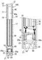
ガス発生器100は、長尺略円柱状の外形を有しており、ハウジング10と、ハウジング10の一方の開口端に取付けられているホルダ20と、ハウジング10の他方の開口端を閉塞するようにハウジング10の他端部に取付けられている閉塞部材12と、を含んでいる。
(Configuration of gas generator 100)
The
ハウジング10は、軸方向の両端に開口を有する長尺の円筒状の部材からなる。閉塞部材12は、所定の厚みを有する円盤状の部材からなり、その周面に後述するかしめ固定のための環状溝部13を有している。このかしめ固定のための環状溝部13は、閉塞部材12の周面に周方向に向かって延びるように形成されている。また、ハウジング10の閉塞部材12が取付けられた側の端部近傍の周壁には、ガス噴出口11が設けられている。このガス噴出口11は、ガス発生器100の内部において発生したガスを外部に噴出するための孔であり、ハウジング10の周方向および軸方向に沿って複数個設けられている。
The
閉塞部材12は、ステンレス鋼、鉄鋼、アルミニウム合金、又はステンレス合金等の金属製であって、所定の厚みを有する円盤状の部材からなる。そして、ハウジング10の一方の開口端に閉塞部材12の一部が内挿された状態で、閉塞部材12の周面に設けられた環状溝部13に対応する部分のハウジング10の周壁を径方向内側に縮径させて(かしめて)当該環状溝部13に係合させることにより、ハウジング10に対する閉塞部材12のかしめ固定が行なわれている。
The
ホルダ20は、ステンレス鋼、鉄鋼、アルミニウム合金、又はステンレス合金等の金属製であって、ハウジング10の軸方向と同方向に延びる中空開口部21を有する筒状の部材からなり、その外周面の所定位置に後述するかしめ固定のための環状溝部23を有している。このかしめ固定のための環状溝部23は、ホルダ20の外周面に周方向に向かって延びるように形成されている。なお、ハウジング10の他方の開口端にホルダ20の一部が内挿された状態で、ホルダ20の外周面に設けられた環状溝部23に対応する部分のハウジング10の周壁を径方向内側に縮径させて(かしめて)当該環状溝部23に係合させることにより、ハウジング10に対するホルダ20のかしめ固定が行なわれている。
The
図1に示すように、ハウジング10の軸方向の一端部(すなわち、ホルダ20寄りの部分)には、ガス発生剤の点火手段としての点火器50が配置されている。なお、点火器50及び点火器50を固定するホルダ20は、後述する粒状のガス発生剤30を燃焼させるための火炎を発生させる点火手段としての機能を有している。
As shown in FIG. 1, an
点火器50は、ホルダ20の中空開口部21に内挿されてかしめ固定されている。より詳細には、ホルダ20は、ハウジング10の内部の空間に面する側の端部にかしめ部20aを有しており、点火器50が中空開口部21に内挿されてホルダ20に当て留めされた状態で当該かしめ部20aをかしめることにより、点火器50がホルダ20に挟持されて点火器50がホルダ20に固定されている。
The
より具体的には、点火器50は、一対の端子ピン52を挿通・保持する基枠と、基枠上に取付けられたスクイブカップ50aとを備えており、スクイブカップ50a内に挿入された端子ピン52の先端を連結するように抵抗体(ブリッジワイヤ)が取付けられ、この抵抗体を取り囲むように又はこの抵抗体に接するようにスクイブカップ50a内に点火薬が充填されている。抵抗体としては一般にニクロム線等が利用され、点火薬としては一般にZPP(ジルコニウム・過塩素酸カリウム)、ZWPP(ジルコニウム・タングステン・過塩素酸カリウム)、鉛トリシネート等が利用される。なお、スクイブカップ50a内には、点火薬だけでなくさらに伝火薬を充填してもよいが、点火薬と同時に配置され得る伝火薬としては、ホウ素/硝酸カリウム等に代表される金属/酸化剤からなる組成物、水素化チタン/過塩素酸カリウムからなる組成物、又は、ホウ素/5-アミノテトラゾール/硝酸カリウム/三酸化モリブデンからなる組成物等が用いられる。スクイブカップは、一般に金属製又はプラスチック製である。
More specifically, the
衝突を検知した際には、端子ピン52を介して抵抗体に所定量の電流が流れる。抵抗体に所定量の電流が流れることにより、抵抗体においてジュール熱が発生し、この熱を受けて点火薬が燃焼を開始する。燃焼により生じた高温の火炎は、点火薬を収納しているスクイブカップ50aを破裂させる。抵抗体に電流が流れてから点火器50が作動するまでの時間は、抵抗体にニクロム線を利用した場合には2ミリ秒以下である。
When a collision is detected, a predetermined amount of current flows through the resistor via the
図1に示すように、ハウジング10の内部空間には、ガス発生剤30が収容されている作動ガス生成室17と、フィルタ40が収容されているフィルタ室18と、巻きバネ60が収容されている点火室19と、が設けられている。
As shown in FIG. 1, a working
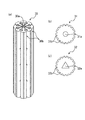
ガス発生剤30は、図3(a)に示したように、軸方向に沿って設けられた貫通孔30aと、外周部に軸方向に沿って設けられた複数の溝部30bとを有し、点火器50によって点火されることによって生じた火炎によって着火され、燃焼することによってガスを発生させる長筒状の一体成型物である。また、ガス発生剤30は、一般に燃料と酸化剤と添加剤とを含む成型体として形成される。燃料としては、たとえばトリアゾール誘導体、テトラゾール誘導体、グアニジン誘導体、アゾジカルボンアミド誘導体、ヒドラジン誘導体等またはこれらの組み合わせが利用される。具体的には、たとえばニトログアニジン、硝酸グアニジン、シアノグアニジン、5−アミノテトラゾール等が好適に利用される。また、酸化剤としては、たとえば塩基性硝酸銅等の塩基性硝酸塩、過塩素酸アンモニウム又は過塩素酸カリウム等の過塩素酸塩、アルカリ金属、アルカリ土類金属、遷移金属、アンモニアから選ばれたカチオンを含む硝酸塩等が利用される。硝酸塩としては、たとえば硝酸ナトリウム、硝酸カリウム等が好適に利用される。また、添加剤としては、バインダ、スラグ形成剤、又は燃焼調整剤等が挙げられる。バインダとしては、たとえばヒドロキシプロピレンメチルセルロース等のセルロース誘導体、カルボキシメチルセルロースの金属塩、ステアリン酸塩等の有機バインダ、合成ヒドロキシタルサイト、酸性白土等の無機バインダが好適に利用可能である。スラグ形成剤としては窒化珪素、シリカ、酸性白土等が好適に利用可能である。また、燃焼調整剤としては、金属酸化物、フェロシリコン、活性炭、グラファイト等が好適に利用可能である。ここで、例えば、ガス発生剤30の組成物が、硝酸グアニジン/塩基性硝酸銅/過塩素酸カリウムであり、このガス発生剤30を構成する硝酸グアニジン/塩基性硝酸銅/過塩素酸カリウムの重量組成比が順に55:39:6であるような場合が特に好ましい。
As shown in FIG. 3A, the
図1に示すように、フィルタ室18は、上述のハウジング10の周壁に設けられたガス噴出口11を介して外部と通じている。また、フィルタ室18内には、中心に略円柱状の空間40aを有した円筒状の部材からなるフィルタ40が収容されている。また、このように円筒状の部材からなるフィルタ40を利用すれば、作動時においてフィルタ室18を流動する作動ガスの流動抵抗が低く抑えられ、効率的なガスの流動が実現可能となる。フィルタ40は、たとえばステンレス鋼或いは鉄鋼等の金属からなる線材、又は、網材を巻き回したもの或いはプレス加工することによって押し固めたもの等が利用される。具体的には、メリヤス編みの金網、平織りの金網、又はクリンプ織りの金属線材の集合体等が利用される。フィルタ40は、作動ガス生成室17にて発生したガスがこのフィルタ40中を通過する際に、ガスが有する高温の熱を奪い取ることによってガスを冷却する冷却手段として機能するとともに、ガス中に含まれるスラグ等を除去する除去手段としても機能する。ここで、フィルタ40の一変形例として、金属からなる略円筒状又はすり鉢状の部品を組み合わせて形成した迷路状流路を有したフィルタを使用してもよい。これにより、作動ガスの進路を様々な方向に変更させることができるので、ガスの冷却及びスラグの除去を行うことが可能である。
As shown in FIG. 1, the
巻きバネ60は、図1(a)、(b)に示したように、一端部がホルダ20に当接しているとともに、他端部がガス発生剤30の一端側の貫通孔の周囲の少なくとも一部に当接して、ガス発生剤30に弾性力を付勢するように設けられている。この付勢により、ガス発生剤30は、ハウジング10内において、巻きバネ60とフィルタ40とに挟まれるようにして固定される。また、巻きバネ60は、図2(a)、(b)に示すように、密に巻かれた大径部60aと、所定間隔を空けるように疎に巻かれた縮径部60bと、を有したものである。なお、巻きバネ60の巻き線のピッチは、大径部60aの方が、縮径部60bより小さくなるように構成されている。ここで、大径部60aは、スクイブカップ50a周りにおいてハウジング10内壁に沿ってらせん状に巻き回されている部分であり、巻きバネ60が縮む際には、大径部60aが縮径部60bよりも先に変形し、縮径部60bはほとんど変形しない。したがって、縮径部60bは、ハウジング10内に取り付けても、所定間隔を保持し続けるようになっている。また、縮径部60bは大径部60aとの境目からガス発生剤30の方向に向かうに従い、縮径するように巻かれている。また、縮径部60bの頂部は、ガス発生剤30の一端部側の径方向中心部付近に位置するように巻かれている。ここで、巻きバネ60の一変形例としては、図2(c)に示したように、巻きバネ60の縮径部60bと同形状の部位のみを有した巻きバネ70が挙げられる。
As shown in FIGS. 1A and 1B, the winding
なお、ガス発生器100のホルダ20が配置された方の端部には、雌型コネクタ(不図示)が取付けられる。この雌型コネクタは、ガス発生器100とは別途設けられる衝突検知手段からの信号を伝達するハーネスの雄型コネクタが接続される部位である。雌型コネクタには、必要に応じてショーティングクリップ(不図示)が取付けられる。このショーティングクリップは、ガス発生器100の搬送時等において静電放電等によってシリンダ型のガス発生器100が誤動作することを防止するために取付けられるものであり、エアバッグ装置への組付け段階においてハーネスの雄型コネクタが雌型コネクタに挿し込まれることによってその端子ピン52への接触が解除されるものである。
A female connector (not shown) is attached to the end of the
次に、以上において説明したガス発生器100の作動時における動作について説明する。本実施の形態におけるガス発生器100が組み込まれたエアバッグ装置が搭載された車両が衝突した場合には、車両に別途設けられた衝突検知手段によって衝突が検知され、これに基づいて点火器50が作動する。点火器50が作動すると、点火薬の燃焼によって点火器50内の圧力が上昇し、これによって点火器50のスクイブカップ50a先端が破裂し、火炎が点火器50のスクイブカップ50a先端から外部(点火室19)へと流出する。次に、この流出した火炎の流路は、直接、ガス発生剤30に向かうものと、図1(b)において太線の矢印で示したように、巻きバネ60の縮径部60bに衝突して変更され、ガス発生剤30の貫通孔30a側へ流れやすくなるものと、ハウジングの内壁側に流れて、ガス発生剤30の溝部30bへ流れやすくなるものとに分流される。これにより、該火炎は拡散するので、ガス発生剤30の表面に広く接触し、ガス発生剤30は燃焼しやすくなる。すなわち、該火炎とガス発生剤30との接触面積が従来よりも大きくなることになるので、ガス発生剤30の着火効率がよくなる。
Next, the operation | movement at the time of the action | operation of the
このようにして流れ込んだ火炎により、ガス発生剤30は着火されて燃焼し、多量のガスを発生させる。このガス発生剤30の燃焼により、作動ガス生成室17内の圧力が上昇し、これによって発生したガスがフィルタ室18へと流れ込む。そして、流れ込んだガスは、フィルタ40を経由して所定の温度にまで冷却される。冷却された多量のガスは、ガス噴出口11からガス発生器100の外部へと噴出される。ガス噴出口11から噴出されたガスは、エアバッグの内部に導かれてエアバッグを膨張・展開させる。
The
(ガス発生器100の主な特徴)
本実施形態によれば、巻きバネ60によってガス発生剤30をフィルタ40に押し付けることができるので、ハウジング10内において、作動ガス生成室17内の筒状のガス発生剤30を容易に固定することができる。また、巻きバネ60の縮径部60bは、点火器50からガス発生剤30にかけて徐々に縮径するものであるとともに、縮径部60bの巻き間隔が所定間隔空いているので、点火器50から発生した火炎の流路は、直接、ガス発生剤30に向かうものと、巻きバネ60に衝突して変更され、ガス発生剤30の貫通孔30aへ流れやすくなるものと、ハウジング10の内壁側に流れて、ガス発生剤30の溝部30bへ流れやすくなるものとに分流される。これにより、該火炎は拡散して、ガス発生剤30の表面に広く接触しやすくなり、ガス発生剤30の着火効率がよくなるので、例え従来よりも、ガス発生器100が小型化されたり、長尺状に細型化されたりしても、ガス発生剤30の燃焼性能(例えば、一定時間で所定量のガスを発生させることなど)を設計通りに達成することができる。
(Main features of the gas generator 100)
According to the present embodiment, since the
また、縮径部60bと連続して形成されている大径部60aの外径がハウジング10の内径と近いので、縮径部60bしかない巻きバネを用いた場合に比べて、巻きバネ60を安定して固定することができる。
In addition, since the outer diameter of the
また、巻きバネ60には大径部60aの間隔(ピッチ)が縮径部60bの間隔より小さくなっているため、巻きバネ60が縮む際には、大径部60aが縮径部60bよりも先に変形し、縮径部60bはほとんど変形しない。したがって、縮径部60bは、ハウジング10内に取り付けても、所定間隔を保持し続けるようになっていることから、点火器50の火炎の流路も変化せず、安定した着火を実現することができる。
Moreover, since the space | interval (pitch) of the
さらに、ガス発生剤30の外径がハウジング10の内径と略同一であるので、ハウジング内において、軸と略垂直な方向へのガス発生剤30のずれが生じないので、点火器50から発生した火炎の流路は、設計通りとすることができる。したがって、ガス発生剤30の燃焼性能を設計通りに達成することができる。
Further, since the outer diameter of the
以上、本発明の実施形態について図面に基づいて説明したが、具体的な構成は、これらの実施形態に限定されるものではないと考えられるべきである。本発明の範囲は、上記した実施形態の説明ではなく特許請求の範囲によって示され、さらに特許請求の範囲と均等の意味および範囲内でのすべての変更が含まれる。 As mentioned above, although embodiment of this invention was described based on drawing, it should be thought that a specific structure is not limited to these embodiment. The scope of the present invention is shown not by the above description of the embodiments but by the scope of claims for patent, and further includes all modifications within the meaning and scope equivalent to the scope of claims for patent.
例えば、上記実施形態のガス発生器100のガス発生剤30においては、ハウジング10の内径の大きさに近い外径を有した一体成型された長筒状のものであるが、この代わりに、複数の短筒状のガス発生剤を軸方向に並べた(積層した)ガス発生剤としてもよい。
For example, the
また、ガス発生剤30の代わりに、上視図が図3(b)又は図3(c)のような単孔筒形状のガス発生剤を用いてもよい。すなわち、巻きバネ60が当接し、弾性力を付勢することが可能な端部を有しているものであれば、どのような貫通孔を有していてもよい。例えば、ガス発生剤30には、内部に孔を複数有する多孔筒形状等の成型体を用いてもよい。
Further, instead of the
また、本実施例においては特にガス発生器の気密性を有するための構成は含まれていないが、Oリング又は粘着テープなどを用いた従来公知の部材も当然追加され得る。 In addition, in the present embodiment, a configuration for particularly having the gas-tightness of the gas generator is not included, but a conventionally known member using an O-ring or an adhesive tape may be added as a matter of course.
また、本実施の形態においては、ハウジング10の他端部に閉塞部材12を取付ける構成としたが、このハウジング10の代わりに、深絞り加工によって形成された他端部が有底構造のハウジングを用いてもよい。
In the present embodiment, the closing
また、本実施の形態においては、一端部がスクイブカップ50a周りにおいてハウジング10内壁に沿ってらせん状に巻き回された巻きバネ60を用いたが、この代わりに、一端部が点火器のスクイブカップ周りに螺旋状に密に巻き付けられた大径部と、該大径部からガス発生剤の一端部にかけて縮径し、所定間隔を空けるように疎に巻かれた縮径部と、を有した巻きバネを用いてもよい。すなわち、点火器のスクイブカップの周囲に、巻きバネの少なくとも一端部(好ましくは、巻きバネの大径部)が巻きつけられることによって、ハウジング内において、巻きバネの位置をより安定させることができる。その結果として、点火器から発生した火炎の流路を設計通りとすることができ、引いては、ガス発生剤の燃焼性能を設計通りに達成することができる。
Further, in the present embodiment, the winding
10 ハウジング
11 ガス噴出口
12 閉塞部材
13、23 環状溝部
17 作動ガス生成室
18 フィルタ室
20 ホルダ
20a かしめ部
21 中空開口部
30 ガス発生剤
40 フィルタ
50 点火器
52 端子ピン
60、70 巻きバネ
100 ガス発生器
DESCRIPTION OF
Claims (5)
点火薬を内包しており、前記ハウジングの軸方向の一端部に配置され、前記作動ガス生成室内の前記ガス発生剤を着火燃焼させることが可能なガス発生剤点火手段と、
前記ハウジング内において、一端部が前記ガス発生剤点火手段に当接又は取り付けられ、他端部の少なくとも一部が前記ガス発生剤の一端側の貫通孔の周囲の少なくとも一部に当接して前記ガス発生剤の他端側に弾性力を付勢するように設けられている巻きバネと、
を備え、
前記巻きバネの少なくとも一部は、前記ガス発生剤点火手段から前記ガス発生剤にかけて徐々に縮径するものであるとともに、該縮径部分の巻き間隔が所定間隔空いており、
前記フィルタ室は、前記作動ガス生成室よりも前記ハウジングの軸方向の他端部側に位置し、
前記ハウジングの前記フィルタ室を規定する部分の周壁部には、前記フィルタを通過した作動ガスを外部に噴出するための複数のガス噴出口が設けられ、
前記ガス発生剤点火手段と前記ハウジングの一端部との間が閉塞されるように、前記ガス発生剤点火手段の少なくとも一部が前記ハウジングの一端部によって覆われるとともに、前記ガス発生剤点火手段が前記ハウジングに固定されていることを特徴とするガス発生器。 Working gas in which a working gas is generated by burning a cylindrical gas generating agent having a through hole along the axial direction in the substantially central portion and at least one groove portion along the axial direction on the outer periphery. A long cylindrical housing containing therein a generation chamber and a filter chamber containing a filter through which the working gas generated in the working gas generation chamber passes;
A gas generating agent ignition means including an ignition agent, disposed at one end of the housing in the axial direction, and capable of igniting and burning the gas generating agent in the working gas generation chamber;
In the housing, one end is in contact with or attached to the gas generating agent ignition means, and at least a part of the other end is in contact with at least a part of the periphery of the through hole on one end side of the gas generating agent. A winding spring provided to bias the elastic force to the other end of the gas generating agent;
With
At least a part of the winding spring gradually decreases in diameter from the gas generating agent ignition means to the gas generating agent, and a winding interval of the reduced diameter portion is a predetermined interval,
The filter chamber is located on the other end side in the axial direction of the housing from the working gas generation chamber,
The peripheral wall portion of the portion defining the filter chamber of the housing is provided with a plurality of gas ejection ports for ejecting the working gas that has passed through the filter to the outside.
At least a part of the gas generating agent ignition means is covered with one end of the housing so that a gap between the gas generating agent ignition means and one end of the housing is closed, and the gas generating agent ignition means A gas generator fixed to the housing.
Priority Applications (1)
| Application Number | Priority Date | Filing Date | Title |
|---|---|---|---|
| JP2015123639A JP2017007456A (en) | 2015-06-19 | 2015-06-19 | Gas generator |
Applications Claiming Priority (1)
| Application Number | Priority Date | Filing Date | Title |
|---|---|---|---|
| JP2015123639A JP2017007456A (en) | 2015-06-19 | 2015-06-19 | Gas generator |
Publications (1)
| Publication Number | Publication Date |
|---|---|
| JP2017007456A true JP2017007456A (en) | 2017-01-12 |
Family
ID=57762714
Family Applications (1)
| Application Number | Title | Priority Date | Filing Date |
|---|---|---|---|
| JP2015123639A Pending JP2017007456A (en) | 2015-06-19 | 2015-06-19 | Gas generator |
Country Status (1)
| Country | Link |
|---|---|
| JP (1) | JP2017007456A (en) |
Cited By (5)
| Publication number | Priority date | Publication date | Assignee | Title |
|---|---|---|---|---|
| CN109236497A (en) * | 2018-09-06 | 2019-01-18 | 西安近代化学研究所 | A kind of lateral force pack boronitriding |
| DE102017130996A1 (en) * | 2017-12-21 | 2019-06-27 | Trw Airbag Systems Gmbh | GAS GENERATOR, GAS TANK MODULE, VEHICLE SAFETY SYSTEM AND METHOD FOR MANUFACTURING A GAS GENERATOR |
| US11046283B2 (en) * | 2018-05-18 | 2021-06-29 | Trw Airbag Systems Gmbh | Propellant cage and packing element for a tubular inflator |
| WO2021256067A1 (en) * | 2020-06-15 | 2021-12-23 | 日本化薬株式会社 | Gas generator |
| WO2023047915A1 (en) | 2021-09-22 | 2023-03-30 | 株式会社ダイセル | Gas generator |
-
2015
- 2015-06-19 JP JP2015123639A patent/JP2017007456A/en active Pending
Cited By (7)
| Publication number | Priority date | Publication date | Assignee | Title |
|---|---|---|---|---|
| DE102017130996A1 (en) * | 2017-12-21 | 2019-06-27 | Trw Airbag Systems Gmbh | GAS GENERATOR, GAS TANK MODULE, VEHICLE SAFETY SYSTEM AND METHOD FOR MANUFACTURING A GAS GENERATOR |
| US11046283B2 (en) * | 2018-05-18 | 2021-06-29 | Trw Airbag Systems Gmbh | Propellant cage and packing element for a tubular inflator |
| CN109236497A (en) * | 2018-09-06 | 2019-01-18 | 西安近代化学研究所 | A kind of lateral force pack boronitriding |
| CN109236497B (en) * | 2018-09-06 | 2021-06-15 | 西安近代化学研究所 | Lateral force solid gas generator |
| WO2021256067A1 (en) * | 2020-06-15 | 2021-12-23 | 日本化薬株式会社 | Gas generator |
| JP7436297B2 (en) | 2020-06-15 | 2024-02-21 | 日本化薬株式会社 | gas generator |
| WO2023047915A1 (en) | 2021-09-22 | 2023-03-30 | 株式会社ダイセル | Gas generator |
Similar Documents
| Publication | Publication Date | Title |
|---|---|---|
| JP2017007456A (en) | Gas generator | |
| CN109070834B (en) | Gas generator | |
| KR20120033300A (en) | Gas generator | |
| EP1944202A1 (en) | Gas generator | |
| JP2017081344A (en) | Gas generator | |
| JP6265855B2 (en) | Gas generator | |
| WO2022138134A1 (en) | Gas generator | |
| JP6399959B2 (en) | Gas generator | |
| JP6310735B2 (en) | Gas generator | |
| WO2022196228A1 (en) | Gas generator | |
| JP2017081343A (en) | Gas generator | |
| JP2012245873A (en) | Gas generator | |
| JP5545703B2 (en) | Gas generator | |
| JP2023112954A (en) | gas generator | |
| JP2011143777A (en) | Gas generator | |
| JP2011031763A (en) | Gas generator and method for manufacturing the same | |
| JP2017043119A (en) | Gas generator | |
| JP6579991B2 (en) | Gas generator | |
| WO2022209798A1 (en) | Gas generator | |
| JP6399781B2 (en) | Gas generator | |
| JP6198302B2 (en) | Gas generator | |
| JP4963917B2 (en) | Gas generator | |
| JP6422327B2 (en) | Gas generator | |
| JP6899019B2 (en) | Gas generator | |
| JP2009241634A (en) | Gas generator and filter for gas generator |