JP2017007202A - Tire molding machine and tire molding method - Google Patents
Tire molding machine and tire molding method Download PDFInfo
- Publication number
- JP2017007202A JP2017007202A JP2015124770A JP2015124770A JP2017007202A JP 2017007202 A JP2017007202 A JP 2017007202A JP 2015124770 A JP2015124770 A JP 2015124770A JP 2015124770 A JP2015124770 A JP 2015124770A JP 2017007202 A JP2017007202 A JP 2017007202A
- Authority
- JP
- Japan
- Prior art keywords
- chafer
- pressing
- tire
- roller
- tire molding
- Prior art date
- Legal status (The legal status is an assumption and is not a legal conclusion. Google has not performed a legal analysis and makes no representation as to the accuracy of the status listed.)
- Pending
Links
- 238000000465 moulding Methods 0.000 title claims abstract description 36
- 238000000034 method Methods 0.000 title claims abstract description 19
- 238000003825 pressing Methods 0.000 claims abstract description 75
- 241000254043 Melolonthinae Species 0.000 claims abstract description 54
- XEEYBQQBJWHFJM-UHFFFAOYSA-N Iron Chemical compound [Fe] XEEYBQQBJWHFJM-UHFFFAOYSA-N 0.000 claims description 12
- 229910052751 metal Inorganic materials 0.000 claims description 11
- 239000002184 metal Substances 0.000 claims description 11
- 229910052742 iron Inorganic materials 0.000 claims description 6
- 230000007547 defect Effects 0.000 abstract description 16
- 238000012360 testing method Methods 0.000 description 14
- 238000002474 experimental method Methods 0.000 description 8
- 229910000831 Steel Inorganic materials 0.000 description 5
- 239000010959 steel Substances 0.000 description 5
- JOYRKODLDBILNP-UHFFFAOYSA-N Ethyl urethane Chemical compound CCOC(N)=O JOYRKODLDBILNP-UHFFFAOYSA-N 0.000 description 4
- 239000004677 Nylon Substances 0.000 description 4
- 238000002788 crimping Methods 0.000 description 4
- 239000000463 material Substances 0.000 description 4
- 229920001778 nylon Polymers 0.000 description 4
- 238000011156 evaluation Methods 0.000 description 2
- 150000002739 metals Chemical class 0.000 description 2
- 238000012545 processing Methods 0.000 description 2
- 229910001208 Crucible steel Inorganic materials 0.000 description 1
- 229910052782 aluminium Inorganic materials 0.000 description 1
- XAGFODPZIPBFFR-UHFFFAOYSA-N aluminium Chemical compound [Al] XAGFODPZIPBFFR-UHFFFAOYSA-N 0.000 description 1
- 230000006835 compression Effects 0.000 description 1
- 238000007906 compression Methods 0.000 description 1
- 230000007797 corrosion Effects 0.000 description 1
- 238000005260 corrosion Methods 0.000 description 1
- 230000002950 deficient Effects 0.000 description 1
- 238000010586 diagram Methods 0.000 description 1
- 238000009826 distribution Methods 0.000 description 1
- 238000005516 engineering process Methods 0.000 description 1
- 238000007689 inspection Methods 0.000 description 1
- 238000003754 machining Methods 0.000 description 1
- 239000000203 mixture Substances 0.000 description 1
- 238000012986 modification Methods 0.000 description 1
- 230000004048 modification Effects 0.000 description 1
- 230000000630 rising effect Effects 0.000 description 1
- 102200082816 rs34868397 Human genes 0.000 description 1
- 229910001220 stainless steel Inorganic materials 0.000 description 1
- 239000010935 stainless steel Substances 0.000 description 1
- 238000004804 winding Methods 0.000 description 1
Images
Landscapes
- Tyre Moulding (AREA)
Abstract
Description
本発明は、生タイヤの成形に際して円筒状のフォーマー上に重ね合わせて巻き付けられたゴム部材を圧着する押圧ローラーを備えているタイヤ成形機および前記タイヤ成形機を用いて行う生タイヤを成形するタイヤ成形方法に関する。 The present invention relates to a tire molding machine provided with a pressure roller that presses a rubber member that is overlapped and wound on a cylindrical former at the time of molding a green tire, and a tire for molding a green tire that is used by using the tire molding machine. The present invention relates to a molding method.
生タイヤの成形に際しては、円筒状のフォーマー上に種々のゴム材料を巻き付けた後、圧着させることにより1stカバーが成形されるが、その工程の1つに、チェーファーとインナーとを圧着させる工程がある(例えば、特許文献1)。 When forming a raw tire, a 1st cover is formed by winding various rubber materials on a cylindrical former and then pressing them. One of the steps is a step of pressing the chafer and the inner. (For example, Patent Document 1).
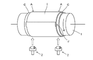
図4は、このチェーファーとインナーとの圧着工程を説明する図である。図4に示すように、まず、円筒状のフォーマー1の両側端部にチェーファーCを巻付けた後、中央部にインナーIを巻き付けてインナーIの始端部と終端部をジョイントしてインナージョイント部Jを形成する。次いで、フォーマー1を図4中の矢印の方向に回転させながら、チェーファーCとインナーIとが重ね合わされた部分であるチェーファーアッセンブリ部Aを押圧ローラー2で押圧し、チェーファーCとインナーIとを圧着させる。
FIG. 4 is a diagram for explaining the crimping process between the chafer and the inner. As shown in FIG. 4, first, after the chafer C is wound around both ends of the cylindrical former 1, the inner I is wound around the center, and the inner end of the inner I is joined to the inner joint. Part J is formed. Next, while rotating the former 1 in the direction of the arrow in FIG. 4, the chafer assembly portion A, which is a portion where the chafer C and the inner I are overlapped, is pressed by the
しかしながら、従来の押圧ローラー2を用いてチェーファーアッセンブリ部Aを押圧した場合、凹凸のあるインナージョイント部JにおけるチェーファーCとインナーIの間の隙間を適切に押圧できないことがある。この場合、生タイヤ成形時にゴム層間に残ったエアーが隙間を移動して一箇所に集まり、成形後の生タイヤのサイドウォール部が風船のように膨らむ不良が発生する恐れがある。
However, when the chafer assembly portion A is pressed using the conventional
そこで、本発明は、インナージョイント部におけるチェーファーとインナーとの隙間を確実に押圧して、成形後の生タイヤのサイドウォール部が膨らむ不良の発生を低減させることができるタイヤ成形技術を提供することを課題とする。 Therefore, the present invention provides a tire molding technology that can reliably press the gap between the chafer and the inner in the inner joint portion, and reduce the occurrence of a defect in which the sidewall portion of the green tire after molding swells. This is the issue.
請求項1に記載の発明は、
円筒状のフォーマー上に巻き付けられたチェーファーとインナーとが重ね合わされたチェーファーアッセンブリ部を押圧ローラーの押圧面により押圧して、前記チェーファーと前記インナーとを圧着するタイヤ成形機であって、
前記押圧ローラーが、前記押圧面にローレット加工が施された金属製の押圧ローラーであり、
さらに、前記押圧ローラーの前記押圧面が、両側縁部から中央部に向かって凸状に傾斜しており、傾斜角度が0°を超え20°以下であることを特徴とするタイヤ成形機である。
The invention described in claim 1
A tire molding machine that presses a chafer assembly portion in which a chafer wound on a cylindrical former and an inner are overlapped by a pressing surface of a pressing roller, and press-bonds the chafer and the inner,
The pressing roller is a metal pressing roller having a knurled finish on the pressing surface,
Further, the tire pressing machine is characterized in that the pressing surface of the pressing roller is inclined in a convex shape from both side edge portions toward the central portion, and the inclination angle is more than 0 ° and not more than 20 °. .
請求項2に記載の発明は、
前記押圧ローラーが鉄製であることを特徴とする請求項1に記載のタイヤ成形機である。
The invention described in
The tire pressing machine according to claim 1, wherein the pressing roller is made of iron.
請求項3に記載の発明は、
請求項1または請求項2に記載のタイヤ成形機を用いて生タイヤを成形するタイヤ成形方法であって、
前記押圧ローラーを用いて、円筒状のフォーマー上に巻き付けられたチェーファーとインナーとが重ね合わされたチェーファーアッセンブリ部を押圧することにより、前記チェーファーと前記インナーとを圧着することを特徴とするタイヤ成形方法である。
The invention according to claim 3
A tire molding method for molding a raw tire using the tire molding machine according to
The chafer and the inner are pressure-bonded by pressing the chafer assembly portion in which the chafer wound on the cylindrical former and the inner are overlapped using the pressing roller. This is a tire molding method.
本発明によれば、インナージョイント部におけるチェーファーとインナーとの隙間を確実に押圧して、成形後の生タイヤのサイドウォール部が膨らむ不良の発生を低減させることができるタイヤ成形技術を提供することができる。 According to the present invention, there is provided a tire molding technique that can surely press the gap between the chafer and the inner in the inner joint portion and reduce the occurrence of a defect in which the sidewall portion of the green tire after molding swells. be able to.
以下、本発明を実施の形態に基づいて説明する。 Hereinafter, the present invention will be described based on embodiments.
1.本実施の形態に係るタイヤ成形機
本実施の形態に係るタイヤ成形機は、円筒状のフォーマー上に巻き付けられたチェーファーとインナーとが重ね合わされたチェーファーアッセンブリ部を押圧ローラーの押圧面により押圧してチェーファーとインナーとを圧着する。
1. Tire forming machine according to the present embodiment The tire forming machine according to the present embodiment presses the chafer assembly portion in which the chafer wound on the cylindrical former and the inner are overlapped by the pressing surface of the pressing roller. Then crimp the chafer and the inner.
そして、本実施の形態に係るタイヤ成形機は、押圧ローラーが押圧面にローレット加工が施された金属製の押圧ローラーであり、さらに、押圧ローラーの押圧面が、両側縁部から中央部に向かって凸状に傾斜しており、その傾斜角度が0°を超え20°以下であることを特徴とする。 In the tire molding machine according to the present embodiment, the pressing roller is a metal pressing roller in which the pressing surface is knurled, and the pressing surface of the pressing roller is directed from the side edges toward the center. Inclined in a convex shape, the inclination angle is more than 0 ° and 20 ° or less.
このように、押圧面にローレット加工および傾斜加工が施された金属製の押圧ローラーを用いてチェーファーアッセンブリ部を押圧することにより、インナージョイント部におけるチェーファーとインナーとの隙間を確実に押圧して、成形後の生タイヤのサイドウォール部が膨らむ不良の発生を低減させることができる。 In this way, the gap between the chafer and the inner in the inner joint portion is surely pressed by pressing the chafer assembly portion using a metal pressing roller whose pressing surface is knurled and inclined. Thus, it is possible to reduce the occurrence of defects in which the sidewall portion of the green tire after molding swells.
2.押圧ローラー
以下、本実施の形態に係るタイヤ成形機に備えられた押圧ローラーについて説明する。
2. Pressing roller Hereinafter, the pressing roller provided in the tire molding machine according to the present embodiment will be described.
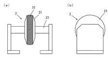
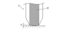
図1は本発明の一実施の形態に係るタイヤ成形機の押圧ローラーの構成を模式的に示す(a)正面図、(b)側面図である。図2は図1に記載の押圧ローラーのローラー本体部の一部分を模式的に示す正面図である。 FIG. 1 is a (a) front view and (b) side view schematically showing a configuration of a pressing roller of a tire molding machine according to an embodiment of the present invention. FIG. 2 is a front view schematically showing a part of the roller main body of the pressing roller shown in FIG.
図1に示すように、押圧ローラー2は、従来と同様に、ローラー本体部21と、ローラー本体部21を回転自在に支持する支持軸23とから構成されている。押圧ローラー2は、例えばエアシリンダーのロッドに固定されており、フォーマーを回転させながらローラー本体部21でチェーファーアッセンブリ部を押圧することにより、チェーファーとインナーとを圧着させる(図4参照)。
As shown in FIG. 1, the
(1)ローラーの材質
従来のタイヤ成形機では、ローラー本体部がMCナイロンやウレタンから構成された押圧ローラーが用いられていた。これに対して、本実施の形態においては、押圧ローラーとしてローラー本体部21が金属製の押圧ローラーを用いる。
(1) Material of Roller In a conventional tire molding machine, a pressure roller having a roller body made of MC nylon or urethane has been used. On the other hand, in this Embodiment, the roller main-
具体的には、硬度が高く、耐圧縮性、耐摩耗性、耐食性に優れる金属が用いられ、このような金属としては、SS400鋼、S45C鋼、SCM鋼などの鉄材の他、鋳物鋼、アルミ鋼、ステンレス鋼等の金属を挙げることができるが、これらの内でも、安価、加工性、強度の観点から、SS400鋼が好ましい。 Specifically, a metal having high hardness and excellent compression resistance, wear resistance, and corrosion resistance is used. Examples of such metals include iron materials such as SS400 steel, S45C steel, and SCM steel, as well as cast steel and aluminum. Although metals, such as steel and stainless steel, can be mentioned, SS400 steel is preferable also from a viewpoint of cheapness, workability, and intensity | strength among these.
このように、ローラー本体部21を金属製にすることにより、MCナイロンやウレタンから構成されていた従来の押圧ローラーに比べて強い圧力で、チェーファーアッセンブリ部を押圧することができる。
Thus, by making the roller
即ち、従来のウレタン製の押圧ローラーでは、チェーファーアッセンブリ部の全体を押さえることができるという利点があるものの、圧力が弱いため、チェーファーアッセンブリ部上のインナージョイント部を押圧した際、チェーファーアッセンブリ部とインナージョイント部の隙間を十分に押さえることができず、隙間が残る場合がある。 That is, the conventional urethane pressure roller has the advantage that the entire chafer assembly can be pressed, but the pressure is weak, so when the inner joint on the chafer assembly is pressed, the chafer assembly The gap between the part and the inner joint part cannot be sufficiently suppressed, and the gap may remain.
また、従来のMCナイロン製の押圧ローラーでは、部分的に強く押さえることはできるが、やはり、チェーファーアッセンブリ部とインナージョイント部の隙間を十分に押さえることができず、隙間が残る場合がある。 In addition, although the conventional MC nylon pressure roller can be pressed down partly, the gap between the chafer assembly part and the inner joint part cannot be sufficiently pressed, and the gap may remain.
これに対して、本実施の形態においては、上記したように、金属製の押圧ローラーを用いてより大きな押圧力でチェーファーアッセンブリ部を押圧することができるため、チェーファーアッセンブリ部とインナージョイント部の隙間を確実に押圧して隙間が残ることを十分に抑制することができる。この結果、本実施の形態においては、成形後の生タイヤのサイドウォール部が膨らむ不良の発生を低減させることができる。 On the other hand, in the present embodiment, as described above, the chafer assembly portion and the inner joint portion can be pressed with a greater pressing force using a metal pressing roller. It is possible to sufficiently suppress the gap from remaining by pressing the gap. As a result, in the present embodiment, it is possible to reduce the occurrence of defects in which the sidewall portion of the green tire after molding swells.
(2)ローレット加工
また、本実施の形態においては、ローラー本体部21の押圧面22にローレット加工が施されており、ローレット加工の凸部によりチェーファーアッセンブリ部Aを十分に押圧することができる。
(2) Knurling In the present embodiment, the
ローレット加工の種類としては、例えば、アヤ目が好ましい。このときの凹凸のピッチは、被押圧物であるチェーファーアッセンブリ部Aの厚み等に応じて適宜設定する。 As the type of knurling, for example, an eyelet is preferable. The pitch of the unevenness at this time is appropriately set according to the thickness of the chafer assembly portion A which is a pressed object.
(3)押圧面の傾斜加工
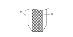
しかし、図3に示すような金属製のローラー本体部21にローレット加工を施したのみの押圧ローラー2を用いた場合、凹の部分での押圧が不十分となる恐れがあるため、本実施の形態においては、図2に示すように、ローラー本体部21の押圧面22に、ローラー本体部21の幅方向の両側縁部から中央部に向かって凸状に傾斜させる傾斜加工が施されている。
(3) Inclination processing of pressing surface However, when the
このような傾斜加工が施されていることにより押圧面22がチェーファーアッセンブリ部Aの全面を十分に押圧することが可能となり、チェーファーアッセンブリ部Aとインナージョイント部Jとの間に隙間が残ることを効果的に抑制することができる。
By applying such an inclination process, the
このとき、押圧面22の傾斜角度θが大きくなり過ぎると、押圧する際にインナーに過大な負荷が掛り、クリース/インナー(CR/IN:Crease/Inner)の不具合が発生する恐れが高くなるため、押圧面22の傾斜角度θは0°を超え20°以下に設定される。
At this time, if the inclination angle θ of the
以下、実施例により本発明をより具体的に説明する。 Hereinafter, the present invention will be described more specifically with reference to examples.
1.実験1
(1)試験例1〜5
本実験では、表1に示すように、ローラーの材質、ローラーの押圧面の形状が異なる種々のローラーを用いて、タイヤサイズ155/65R14 75S EC300HEの生タイヤ用のゴム部材のチェーファーアッセンブリ部を押圧し、チェーファーとインナーとを圧着させた(試験例1〜5)。
1. Experiment 1
(1) Test Examples 1-5
In this experiment, as shown in Table 1, the chafer assembly portion of a rubber member for a raw tire of a tire size 155 / 65R14 75S EC300HE is used by using various rollers having different roller materials and different pressing surface shapes. The chafer and the inner were pressed against each other (Test Examples 1 to 5).
なお、押圧条件は、チェーファー押さえ圧を0.45mpa、チェーファー押さえ出ストロークを75mm、インナー押さえ圧を0.50mpa、インナー押さえ出ストロークを120mmに設定した。 The pressing conditions were set such that the chafer pressing pressure was 0.45 mpa, the chafer pressing stroke was 75 mm, the inner pressing pressure was 0.50 mpa, and the inner pressing stroke was 120 mm.
(2)評価
(a)押圧状態
チェーファーアッセンブリ部の下に感圧紙を配置した状態で押圧を行うことにより、チェーファーアッセンブリ部Aへの押圧状態(押圧力と圧力分布)を調べた。結果を表1に示す。
(2) Evaluation (a) Pressed state The pressed state (pressing force and pressure distribution) to the chafer assembly portion A was examined by pressing with the pressure sensitive paper placed under the chafer assembly portion. The results are shown in Table 1.
(b)風船不良発生率の算出
チェーファーアッセンブリ部を押圧した後に生タイヤを成形し、成形後の生タイヤのサイドウォール部が膨らむ不良(風船不良)が生じているか否かを目視で確認した。そして、試験個数(20000本)中の風船不良が発生している比率を算出した。結果を表1に示す。
(B) Calculation of the occurrence rate of defective balloons After pressing the chafer assembly part, a green tire was molded, and it was visually confirmed whether or not there was a defect (balloon defect) in which the side wall part of the green tire after molding was inflated. . And the ratio which the balloon defect generate | occur | produced in the test number (20000) was calculated. The results are shown in Table 1.
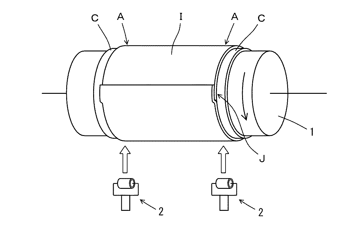
表1より、試験例1、2と試験例3〜5を比較すると、試験例3〜5の場合、風船不良の発生率が低減されていることが分かる。このことから、鉄製のローラーの押圧面にローレット加工を施すことにより、チェーファーとインナーとを適切に押圧して風船不良の発生を抑制できることが確認できた。 From Table 1, comparing Test Examples 1 and 2 and Test Examples 3 to 5, it can be seen that in Test Examples 3 to 5, the incidence of balloon defects is reduced. From this, it was confirmed that by applying knurling to the pressing surface of the iron roller, it is possible to appropriately press the chafer and the inner to suppress the occurrence of balloon defects.
そして、試験例3〜5の中でも、試験例3ではインナージョイント部の周辺(表中の押圧状態の写真において丸で囲った部分)で若干の押圧不良が生じていたことに対して、試験例4、5では押圧不良が生じておらず、風船発生率が大幅に低減されていることが分かる。このことから、押圧面にローレット加工が施された鉄製のローラーに、さらに傾斜加工を施すことにより、チェーファーとインナーとを確実に押圧して風船不良の発生を大幅に低減できることが確認できた。 And among Test Examples 3-5, in Test Example 3, a slight press failure occurred in the vicinity of the inner joint portion (the part circled in the photograph of the pressed state in the table). 4 and 5 show that no pressing failure occurs and the balloon generation rate is greatly reduced. From this, it was confirmed that the iron roller whose knurled surface was subjected to the knurling process was further tilted to reliably press the chafer and the inner to significantly reduce the occurrence of balloon defects. .
2.実験2
(1)試験例6〜12
本実験では、上記した実験1と同様に、表2に示す種々のローラーを用いて、チェーファーアッセンブリ部を押圧した後に生タイヤを成形してCR/INの不具合発生率を調べた(試験例6〜12)。なお、押圧条件を上記した実験1と同じ条件に設定すると共に、実験1と同じ手順で風船不良発生率も算出した。
2.
(1) Test Examples 6-12
In this experiment, similar to Experiment 1 described above, the various tires shown in Table 2 were used to form a raw tire after pressing the chafer assembly, and the CR / IN defect occurrence rate was examined (test example). 6-12). The pressing conditions were set to the same conditions as in Experiment 1 described above, and the balloon defect occurrence rate was also calculated in the same procedure as in Experiment 1.
(2)評価
(a)風船不良発生率の算出
上記したように、実験1と同じ手順で、試験個数(20000本)中の風船不良が発生している比率を算出した。結果を表2に示す。
(2) Evaluation (a) Calculation of Balloon Defect Incidence Rate As described above, the ratio of occurrence of balloon defects in the test number (20,000) was calculated in the same procedure as in Experiment 1. The results are shown in Table 2.
(b)CR/INの不具合の発生率
検査工程において、成形後の生タイヤにCR/INが生じているか否かを検査し、CR/INが発生している本数を測定した後、試験個数中でCR/INの不具合が発生している比率を算出した。結果を表2に示す。
(B) Incidence rate of CR / IN defects In the inspection process, whether or not CR / IN has occurred in the green tires after molding is measured, and the number of CR / IN generated is measured. The ratio of occurrence of CR / IN failures was calculated. The results are shown in Table 2.
表2より、傾斜加工の傾斜角度を30°に設定した試験例12では、風船発生率が低減されている一方で、インナーに負荷が掛かってCR/INの発生率が従来のウレタン製やMCナイロン製のローラーを用いた試験例8〜11に比べて上昇していることが分かる。 From Table 2, in Test Example 12 in which the tilt angle of the tilting process is set to 30 °, the balloon generation rate is reduced, while the load is applied to the inner and the CR / IN generation rate is made of conventional urethane or MC. It turns out that it is rising compared with Test Examples 8 to 11 using a roller made of nylon.
一方、傾斜加工の傾斜角度を20°以下に設定した試験例6、7においては、風船発生率が低減されているだけでなく、CR/INも発生していないことが分かる。 On the other hand, in Test Examples 6 and 7 in which the inclination angle of the inclination processing is set to 20 ° or less, it is understood that not only the balloon generation rate is reduced but also CR / IN is not generated.
以上、本発明を実施の形態に基づいて説明したが、本発明は、上記の実施の形態に限定されるものではない。本発明と同一および均等の範囲内において、上記の実施の形態に対して種々の変更を加えることが可能である。 While the present invention has been described based on the embodiments, the present invention is not limited to the above-described embodiments. Various modifications can be made to the above-described embodiment within the same and equivalent scope as the present invention.
1 フォーマー
2 押圧ローラー
21 ローラー本体部
22 押圧面
23 支持軸
A チェーファーアッセンブリ部
C チェーファー
I インナー
J インナージョイント部
θ 傾斜角度
DESCRIPTION OF SYMBOLS 1 Former 2 Pressing
Claims (3)
前記押圧ローラーが、前記押圧面にローレット加工が施された金属製の押圧ローラーであり、
さらに、前記押圧ローラーの前記押圧面が、両側縁部から中央部に向かって凸状に傾斜しており、傾斜角度が0°を超え20°以下であることを特徴とするタイヤ成形機。 A tire molding machine that presses a chafer assembly portion in which a chafer wound on a cylindrical former and an inner are overlapped by a pressing surface of a pressing roller, and press-bonds the chafer and the inner,
The pressing roller is a metal pressing roller having a knurled finish on the pressing surface,
Furthermore, the pressing surface of the pressing roller is inclined in a convex shape from both side edge portions toward the central portion, and the inclination angle is more than 0 ° and not more than 20 °.
前記押圧ローラーを用いて、円筒状のフォーマー上に巻き付けられたチェーファーとインナーとが重ね合わされたチェーファーアッセンブリ部を押圧することにより、前記チェーファーと前記インナーとを圧着することを特徴とするタイヤ成形方法。 A tire molding method for molding a raw tire using the tire molding machine according to claim 1 or 2,
The chafer and the inner are pressure-bonded by pressing the chafer assembly portion in which the chafer wound on the cylindrical former and the inner are overlapped using the pressing roller. Tire molding method.
Priority Applications (1)
| Application Number | Priority Date | Filing Date | Title |
|---|---|---|---|
| JP2015124770A JP2017007202A (en) | 2015-06-22 | 2015-06-22 | Tire molding machine and tire molding method |
Applications Claiming Priority (1)
| Application Number | Priority Date | Filing Date | Title |
|---|---|---|---|
| JP2015124770A JP2017007202A (en) | 2015-06-22 | 2015-06-22 | Tire molding machine and tire molding method |
Publications (1)
| Publication Number | Publication Date |
|---|---|
| JP2017007202A true JP2017007202A (en) | 2017-01-12 |
Family
ID=57762317
Family Applications (1)
| Application Number | Title | Priority Date | Filing Date |
|---|---|---|---|
| JP2015124770A Pending JP2017007202A (en) | 2015-06-22 | 2015-06-22 | Tire molding machine and tire molding method |
Country Status (1)
| Country | Link |
|---|---|
| JP (1) | JP2017007202A (en) |
Cited By (2)
| Publication number | Priority date | Publication date | Assignee | Title |
|---|---|---|---|---|
| JP2022028462A (en) * | 2020-08-03 | 2022-02-16 | Toyo Tire株式会社 | Manufacturing method and manufacturing device of pneumatic tire |
| JP2022056045A (en) * | 2020-09-29 | 2022-04-08 | 住友ゴム工業株式会社 | Tire component molding apparatus and tire manufacturing method using this apparatus |
-
2015
- 2015-06-22 JP JP2015124770A patent/JP2017007202A/en active Pending
Cited By (3)
| Publication number | Priority date | Publication date | Assignee | Title |
|---|---|---|---|---|
| JP2022028462A (en) * | 2020-08-03 | 2022-02-16 | Toyo Tire株式会社 | Manufacturing method and manufacturing device of pneumatic tire |
| JP2022056045A (en) * | 2020-09-29 | 2022-04-08 | 住友ゴム工業株式会社 | Tire component molding apparatus and tire manufacturing method using this apparatus |
| JP7574594B2 (en) | 2020-09-29 | 2024-10-29 | 住友ゴム工業株式会社 | Tire component molding device and tire manufacturing method using the same |
Similar Documents
| Publication | Publication Date | Title |
|---|---|---|
| CN1046881C (en) | Roll Hardening Method for Parts | |
| JP2017007202A (en) | Tire molding machine and tire molding method | |
| US20170128998A1 (en) | Formed material manufacturing method and formed material | |
| CN109128476B (en) | Electron beam welding processing method of stainless steel frame structure | |
| CN105234636B (en) | Stainless steel ring forging welding procedure | |
| CN104148457B (en) | A kind of sheet material tubulation furling plate round machine of modified node method | |
| JP4697728B2 (en) | Pressure roller and pressure device | |
| JP4843401B2 (en) | Forging method and anvil used for the forging method | |
| JP6529235B2 (en) | Tire molding presser and tire molding method | |
| RU2543657C1 (en) | Production method of longitudinally welded main pipes | |
| CN103056641B (en) | A kind of template with roller-replacing function for flattening machine and roll change localization method | |
| JP4816015B2 (en) | High-efficiency manufacturing method for ERW pipes with good weld characteristics | |
| JP4783792B2 (en) | Method and edge bending press apparatus for edge bending a thin strip strip formed into an open seam tube | |
| JP6899998B2 (en) | Pressing roller and pressing device for tire molding and tire molding device | |
| JP6282006B2 (en) | Steel pipe manufacturing method and manufacturing apparatus thereof | |
| JP2016159304A (en) | Roll chock repair method for rolling mill and rolling mill | |
| JP2017039287A (en) | Side wall press roller and sticking method of side wall rubber | |
| JP5765757B2 (en) | Method for manufacturing annular shaped material | |
| CN115008278B (en) | Backup roll repairing method | |
| JP5055848B2 (en) | Manufacturing method of electric resistance welded tube with good weld characteristics | |
| JP4720479B2 (en) | High-efficiency manufacturing method for ERW pipes with good weld characteristics | |
| JP2014205265A (en) | Joint part application device and joint part application method | |
| CN115055925B (en) | Plate rolling process | |
| JP2017209853A (en) | Low cover crimping device and low cover crimping method | |
| CN103388144A (en) | Remanufacture method for efficacy-losing hydraulic cylinder |