JP2017006202A - Implement for simple bar-like cosmetic and simple bar-like cosmetic - Google Patents
Implement for simple bar-like cosmetic and simple bar-like cosmetic Download PDFInfo
- Publication number
- JP2017006202A JP2017006202A JP2015122133A JP2015122133A JP2017006202A JP 2017006202 A JP2017006202 A JP 2017006202A JP 2015122133 A JP2015122133 A JP 2015122133A JP 2015122133 A JP2015122133 A JP 2015122133A JP 2017006202 A JP2017006202 A JP 2017006202A
- Authority
- JP
- Japan
- Prior art keywords
- tool body
- tool
- cosmetic
- cap
- lipstick
- Prior art date
- Legal status (The legal status is an assumption and is not a legal conclusion. Google has not performed a legal analysis and makes no representation as to the accuracy of the status listed.)
- Granted
Links
- 239000002537 cosmetic Substances 0.000 title claims abstract description 267
- 230000002093 peripheral effect Effects 0.000 claims abstract description 66
- 239000000463 material Substances 0.000 claims description 7
- 229920003002 synthetic resin Polymers 0.000 description 11
- 239000000057 synthetic resin Substances 0.000 description 11
- 210000003811 finger Anatomy 0.000 description 8
- 238000000465 moulding Methods 0.000 description 8
- 238000003856 thermoforming Methods 0.000 description 7
- 239000007788 liquid Substances 0.000 description 5
- 238000001746 injection moulding Methods 0.000 description 4
- 238000000034 method Methods 0.000 description 4
- 239000003086 colorant Substances 0.000 description 3
- 238000004519 manufacturing process Methods 0.000 description 3
- -1 polyethylene terephthalate Polymers 0.000 description 3
- 210000003813 thumb Anatomy 0.000 description 3
- 229920008790 Amorphous Polyethylene terephthalate Polymers 0.000 description 2
- PPBRXRYQALVLMV-UHFFFAOYSA-N Styrene Chemical compound C=CC1=CC=CC=C1 PPBRXRYQALVLMV-UHFFFAOYSA-N 0.000 description 2
- 230000006870 function Effects 0.000 description 2
- 230000008569 process Effects 0.000 description 2
- 229920005989 resin Polymers 0.000 description 2
- 239000011347 resin Substances 0.000 description 2
- 239000007787 solid Substances 0.000 description 2
- 238000007666 vacuum forming Methods 0.000 description 2
- 239000004698 Polyethylene Substances 0.000 description 1
- 239000004743 Polypropylene Substances 0.000 description 1
- 239000004793 Polystyrene Substances 0.000 description 1
- 230000008901 benefit Effects 0.000 description 1
- 230000015572 biosynthetic process Effects 0.000 description 1
- 230000008859 change Effects 0.000 description 1
- 230000000694 effects Effects 0.000 description 1
- 238000009434 installation Methods 0.000 description 1
- 239000007934 lip balm Substances 0.000 description 1
- 239000003973 paint Substances 0.000 description 1
- 229920005668 polycarbonate resin Polymers 0.000 description 1
- 239000004431 polycarbonate resin Substances 0.000 description 1
- 229920001225 polyester resin Polymers 0.000 description 1
- 239000004645 polyester resin Substances 0.000 description 1
- 229920000573 polyethylene Polymers 0.000 description 1
- 229920000139 polyethylene terephthalate Polymers 0.000 description 1
- 239000005020 polyethylene terephthalate Substances 0.000 description 1
- 229920005672 polyolefin resin Polymers 0.000 description 1
- 229920001155 polypropylene Polymers 0.000 description 1
- 229920002223 polystyrene Polymers 0.000 description 1
- 230000035807 sensation Effects 0.000 description 1
- 229920005992 thermoplastic resin Polymers 0.000 description 1
- 239000013585 weight reducing agent Substances 0.000 description 1
Images


Landscapes
- Cosmetics (AREA)
Abstract
Description
本発明は、簡易棒状化粧品用の用具と、簡易棒状化粧品に関する。 The present invention relates to a tool for a simple bar-shaped cosmetic and a simple bar-shaped cosmetic.
例えば、店頭において口紅の試供品、即ち、リップサンプルとして使用されているものは、試供品として扱われているものの、実際に販売する口紅の実売品、即ち、本品と同じものである。尚、口紅の本品は、化粧料としての口紅が棒状に形成されて容器に収容されており、口紅の量が多いことから繰り返し使用でき、長期に亘って使用できる。このような口紅の本品が試供品として店頭で使用される場合には、一本の試供品を使い回すことになるため、他人が使用したものを自分の唇に塗ることに対して抵抗を感じる人も多い。 For example, a lipstick sample, that is, a lip sample used at a storefront, is treated as a sample, but is the same as an actual lipstick product that is actually sold, that is, this product. In addition, this product of lipstick can be used repeatedly over a long period of time because the lipstick as a cosmetic material is formed in a stick shape and stored in a container, and the amount of lipstick is large. When such a lipstick product is used as a free sample at the store, you will be using a single sample for free. Many people feel it.
これに対して、下記特許文献1のように、一回あるいは数回塗ることができる程度の少量の口紅を本体の上面に付着させた、使い捨てを前提とした専用の試供品も提案されている。使用に際しては、本体の外周面を指先で摘むようにする他、本体が円筒状であって下端が開口した形状であることから、その本体の内側に人差し指を下側から差し込んで本体の上面に付着した口紅を唇に塗るという使用方法も提案されている。そして、このような口紅の試供品では、一本の口紅の本品を複数の人が使用するということがないので衛生的であるという利点がある。
On the other hand, as in
しかしながら、本体の横断面形状が円形であるため、人差し指に対して本体の上面の向きが一定となりにくい。本体の上面は、口紅の本品と同様に、所定の方向に向けて傾斜した傾斜面とされており、その傾斜面の上部が上側となり、傾斜面の下部が下側となる姿勢にして唇に当てるようにするが、本体の断面が円形であるために、例えば人差し指を本体に差し込んだ状態では、傾斜面の傾斜方向が横を向いたり斜めを向いたりすることがある。つまり、人差し指に対して本体の中心軸回りの向きが使用の都度変化しやすく、使用に際して本体の傾斜面の向きが所定方向となるように本体を回転させて調整しなければならない。 However, since the cross-sectional shape of the main body is circular, the orientation of the upper surface of the main body with respect to the index finger is difficult to be constant. The upper surface of the main body, like the lipstick product, has an inclined surface inclined in a predetermined direction, with the upper part of the inclined surface on the upper side and the lower part of the inclined surface on the lower side. However, since the cross section of the main body is circular, for example, when the index finger is inserted into the main body, the inclined direction of the inclined surface may turn sideways or obliquely. That is, the orientation around the central axis of the main body with respect to the index finger is likely to change every time it is used, and the main body must be rotated and adjusted so that the orientation of the inclined surface of the main body is in a predetermined direction.
また、本体が円筒形であるため、上面に付着させる口紅の付着面積を拡大することにも限界がある。口紅は細いほど細かい部分をきっちりと塗ることができ、特に上唇の上縁の輪郭を正確に描くことができる。しかしながら、上記試供品は、口紅の本品とは異なり、本体の上面に口紅を薄く付着させた構成であるため、本体を細くすると口紅の量が不足する可能性がある。本体の上面が傾斜面となっているので、本体の上面が傾斜していない平坦面である場合に比して付着面積は拡大されるものの、上面を傾斜させたことによる付着面積の拡大は僅かであるため、本体の上端部を細くした場合には、やはり口紅の量が不足する可能性がある。その一方、逆に、本体を太くすると口紅の付着面積が拡大し、それに伴って口紅の量も容易に増加させることができる。しかしながら、逆に、上唇等の細かい部分を正確に塗ることが難しくなる。 In addition, since the main body is cylindrical, there is a limit to expanding the adhesion area of the lipstick that adheres to the upper surface. The thinner the lipstick, the finer it can be painted, especially the upper edge of the upper lip. However, unlike the lipstick product, the above sample has a structure in which the lipstick is thinly attached to the upper surface of the main body. Therefore, if the main body is thinned, the amount of lipstick may be insufficient. Since the upper surface of the main body is an inclined surface, the adhesion area is enlarged as compared to the case where the upper surface of the main body is a flat surface that is not inclined, but the adhesion area due to the inclination of the upper surface is slightly increased. Therefore, when the upper end portion of the main body is narrowed, the amount of lipstick may still be insufficient. On the other hand, when the main body is thickened, the adhesion area of the lipstick is enlarged, and the amount of lipstick can be easily increased accordingly. However, on the contrary, it is difficult to accurately apply fine parts such as the upper lip.
それゆえに本発明は上記従来の問題点に鑑みてなされ、使いやすさが向上した簡易棒状化粧品用の用具と簡易棒状化粧品を提供することを課題とする。 Therefore, the present invention has been made in view of the above-mentioned conventional problems, and an object thereof is to provide a tool for a simple bar-shaped cosmetic product and a simple bar-shaped cosmetic product that are improved in ease of use.
本発明は、上記課題を解決すべくなされたものであって、本発明に係る簡易棒状化粧品用の用具は、上面に化粧料が付着される用具本体を備えた簡易棒状化粧品用の用具であって、用具本体の上面は、所定方向に傾斜しており、用具本体の外周面の横断面形状は、第一の方向を長軸方向とし該第一の方向と直交する第二の方向を短軸方向とする非円形であり、用具本体の上面の傾斜方向は、用具本体の外周面の長軸方向であることを特徴とする。尚、非円形とは、例えば楕円形や長円形、オーバル形等である。また、簡易棒状化粧品は、試供品として配布されたり店頭で使用されたりしてもよいし、あるいは、簡便な化粧品として販売されてもよい。例えば、一回あるいは数回の使用に適した少量の化粧料を付着させたものとすることができる。 The present invention has been made to solve the above-mentioned problems, and the simple bar-shaped cosmetic tool according to the present invention is a simple bar-shaped cosmetic tool provided with a tool body on which cosmetics are attached to the upper surface. The upper surface of the tool body is inclined in a predetermined direction, and the cross-sectional shape of the outer peripheral surface of the tool body has a first direction as a major axis direction and a second direction perpendicular to the first direction as a short direction. The tool body is non-circular, and the inclination direction of the upper surface of the tool body is the major axis direction of the outer peripheral surface of the tool body. The non-circular shape is, for example, an elliptical shape, an oval shape, an oval shape, or the like. In addition, the simple bar-shaped cosmetic product may be distributed as a sample or used at a store, or may be sold as a simple cosmetic product. For example, a small amount of cosmetic suitable for one or several uses can be attached.
該構成の簡易棒状化粧品用の用具は、用具本体の上面に例えば化粧料として口紅が付着される。棒状化粧料としては口紅の他、例えば、リップクリームやスチックアイシャドウ、スチックファンデーション等があるが、以下、口紅の場合を例にして説明する。また、以下、化粧料そのものとしての口紅を口紅化粧料と称し、口紅化粧料を備えた化粧品全体としての口紅を口紅化粧品と称して、両者を区別することがある。 The simple bar-shaped cosmetic tool having such a configuration has a lipstick attached as, for example, a cosmetic on the upper surface of the tool body. In addition to lipsticks, for example, lip balm, stick eye shadow, stick foundation, and the like are used as stick-shaped cosmetics. Hereinafter, the case of lipstick will be described as an example. Hereinafter, the lipstick as the cosmetic itself is referred to as a lipstick cosmetic, and the lipstick as the entire cosmetic provided with the lipstick cosmetic is referred to as a lipstick cosmetic.
上記構成の簡易棒状化粧品用の用具は、用具本体の外周面の横断面形状が楕円形等の非円形となっていて、横断面形状が円形のものとは異なり、用具本体の形状に方向性がある。即ち、用具本体の外周面の横断面形状は、第一の方向の長さが相対的に長く第二の方向の長さが相対的に短くなっている。従って、用具本体を掴むと、用具本体の形状の方向性が視覚のみならず触覚によっても容易に把握することができる。そして、その用具本体の上面の傾斜方向が用具本体の外周面の長軸方向となっているので、用具本体の外周面の長軸方向が顔を基準として前後方向あるいは上下方向となるように用具本体を掴めば、用具本体の上面の傾斜方向も自動的に前後方向あるいは上下方向となり、用具本体の上面の向きを唇に容易に合わせることができる。 The tool for simple bar-shaped cosmetics having the above configuration has a non-circular cross-sectional shape such as an ellipse on the outer peripheral surface of the tool main body, and the direction of the shape of the tool main body is different from a circular cross-sectional shape. There is. That is, the cross-sectional shape of the outer peripheral surface of the tool body has a relatively long length in the first direction and a relatively short length in the second direction. Therefore, when the tool main body is grasped, the directionality of the shape of the tool main body can be easily grasped not only visually but also by tactile sensation. And since the inclination direction of the upper surface of the tool body is the major axis direction of the outer peripheral surface of the tool body, the tool is such that the major axis direction of the outer peripheral surface of the tool body is the front-rear direction or the vertical direction with respect to the face. If the main body is grasped, the inclination direction of the upper surface of the tool main body automatically becomes the front-rear direction or the vertical direction, and the direction of the upper surface of the tool main body can be easily adjusted to the lips.
また、用具本体の横断面形状が楕円形等の非円形であるので、傾斜している用具本体の上面は、より一層扁平率の大きい楕円形等の非円形となる。即ち、上面の傾斜方向が長軸方向となり、上面の傾斜方向と直交する方向が短軸方向となるが、その長軸方向の両端部においては曲率半径が小さくなっている。従って、長軸方向の両端部のうちの一方である上側の端部を上唇の上縁に当てるようにして上唇の輪郭を正確に描くことができる。即ち、細い口紅化粧品を用いた場合と同様に細かい部分を容易且つ正確に塗ることができる。一方、用具本体の上面は長軸方向の長さが長いので、例えば、下唇を塗るような場合にはその長軸方向の長さを利用して一度に大きな面積を塗ることができる。即ち、太い口紅化粧品を用いた場合と同様に広い面積を効率良く塗ることができる。また、用具本体が細い円形のものとは異なり、口紅化粧料の付着量も容易に確保できる。このように、一本の簡易棒状化粧品で細い口紅化粧品と太い口紅化粧品あるいは標準の太さの口紅化粧品の両方を使用したときと同等の使用感が得られる。 Moreover, since the cross-sectional shape of the tool body is a non-circular shape such as an ellipse, the inclined upper surface of the tool body is a non-circular shape such as an ellipse having a higher flatness. That is, the inclination direction of the upper surface is the major axis direction, and the direction orthogonal to the inclination direction of the upper surface is the minor axis direction, but the radius of curvature is small at both ends in the major axis direction. Therefore, it is possible to accurately draw the contour of the upper lip so that the upper end, which is one of both ends in the long axis direction, is brought into contact with the upper edge of the upper lip. That is, as with the case of using a thin lipstick cosmetic, a fine portion can be applied easily and accurately. On the other hand, since the upper surface of the tool body has a long length in the major axis direction, for example, when the lower lip is painted, a large area can be painted at once using the length in the major axis direction. That is, a large area can be efficiently applied as in the case of using a thick lipstick cosmetic. In addition, unlike a thin circular tool body, the amount of lipstick cosmetic can be easily secured. In this way, the same usability as when using both a thin lipstick cosmetic and a thick lipstick cosmetic or a standard lipstick cosmetic with a single simple stick-shaped cosmetic product is obtained.
特に、用具本体は、上端閉口で下端開口の筒状であり、該用具本体の下端にはフランジ部が全周に亘って形成されていることが好ましい。用具本体は中実状であってもよいが、中空状のものが軽くて低コストに製造できるので好ましい。また、横断面形状が非円形であるので、横断面形状が円形の場合に比して容易に成形でき、高い精度を確保できる。特に、用具本体の上下方向の長さ、即ち全長が、用具本体の下端の開口部における長軸方向の長さに比して長いような、深型の用具本体である場合には、用具本体を合成樹脂シートから熱成形により形成する場合、横断面形状を非円形にすることで成形が容易になる。そして、用具本体を上端閉口で下端開口の筒状とすることにより、用具本体は天面部と胴部とフランジ部とを備えた構成となるが、その天面部の上面を口紅化粧料の付着部とすることができる。また、下端が開口していることから下端の開口部から用具本体の内側に指先を挿入して用具本体の胴部やフランジ部を掴むこともできる。例えば、人差し指を用具本体に差し込んで親指と共に用具本体の胴部やフランジ部を掴んで保持するということもできる。更に、用具本体の下端が開口していても、その下端にフランジ部が全周に亘って形成されているので、用具本体の下端の強度を容易に確保できる。尚、用具本体同士を上下に積み重ねることができる構成としてもよい。用具本体同士を積み重ねた際に、下側の用具本体の天面部と上側の用具本体の天面部とが上下方向に所定間隔離間するように構成することで、下側の用具本体の口紅化粧料が上側の用具本体に付着することを防止できる。例えば、積み重ねた複数の用具本体をまとめて掴んで上側の用具本体の口紅化粧料を塗るという使用方法も可能である。また、積み重ねられた用具本体同士を分離する場合、用具本体の下端にフランジ部が形成されているので、指先をフランジ部に引っ掛けるようにすることで容易に分離できる。 In particular, it is preferable that the tool body has a cylindrical shape with an upper end closed and a lower end opening, and a flange portion is formed over the entire circumference at the lower end of the tool body. The tool body may be solid, but a hollow one is preferable because it is light and can be manufactured at low cost. Further, since the cross-sectional shape is non-circular, it can be easily molded as compared with the case where the cross-sectional shape is circular, and high accuracy can be ensured. In particular, in the case of a deep tool body in which the length of the tool body in the vertical direction, that is, the overall length is longer than the length in the major axis direction at the lower end opening of the tool body, the tool body Is formed from a synthetic resin sheet by thermoforming, it becomes easy to form by making the cross-sectional shape non-circular. And by making the tool main body into a cylindrical shape with the upper end closed and the lower end opening, the tool main body has a configuration including a top surface portion, a trunk portion, and a flange portion. It can be. Further, since the lower end is opened, a fingertip can be inserted into the inside of the tool main body from the opening at the lower end so as to grasp the trunk portion and the flange portion of the tool main body. For example, the index finger can be inserted into the tool body, and the body part and the flange part of the tool body can be grasped and held together with the thumb. Furthermore, even if the lower end of the tool main body is open, the strength of the lower end of the tool main body can be easily ensured because the flange portion is formed at the lower end of the tool main body. In addition, it is good also as a structure which can pile up tool main bodies up and down. The lipstick cosmetic for the lower tool body is configured such that when the tool bodies are stacked, the top surface part of the lower tool body and the top surface part of the upper tool body are spaced apart by a predetermined distance in the vertical direction. Can be prevented from adhering to the upper tool body. For example, a method of using a plurality of stacked device bodies together and applying lipstick cosmetics on the upper device body is also possible. Moreover, when separating the stacked tool main bodies, since the flange part is formed at the lower end of the tool main body, it can be easily separated by hooking the fingertip on the flange part.
また、用具本体の上部に被せられる横断面形状が非円形のキャップを備え、該キャップは、上端閉口で下端開口の筒状であり、該キャップの下端にはフランジ部が全周に亘って形成されていることが好ましい。該構成によれば、キャップを備えているので、上面の口紅化粧料を保護することができ、特に店頭から持ち帰る場合等、携帯時において効果が大きい。また、キャップの下端にフランジ部が全周に亘って形成されているので、キャップの下端の強度も容易に確保でき、また、用具本体に被せたキャップを用具本体から取り外す際に、指先をキャップのフランジ部に引っ掛けてキャップを用具本体から容易に外すことができる。また、キャップを用具本体に着脱する際にキャップのフランジ部の外縁を内外方向に掴むと、キャップの胴部の外周面を掴む場合に比して、指先が用具本体の上面の口紅化粧料から径方向外側に離れるので、キャップの着脱に際して、指先に口紅化粧料が付きにくくなる。 In addition, a cap having a non-circular cross-sectional shape covering the upper part of the tool body is provided, and the cap has a cylindrical shape with a closed upper end and a lower end opening, and a flange portion is formed at the lower end of the cap over the entire circumference. It is preferable that According to this configuration, since the cap is provided, the lipstick cosmetics on the upper surface can be protected, and the effect is particularly great when carried around, such as when taking it home from a store. Moreover, since the flange part is formed on the lower end of the cap over the entire circumference, the strength of the lower end of the cap can be easily secured, and when removing the cap on the tool body from the tool body, cap the fingertip. The cap can be easily removed from the tool body by hooking it on the flange portion. Also, when the outer edge of the flange part of the cap is gripped inward and outward when attaching and detaching the cap to the tool body, the fingertips come from the lipstick cosmetics on the upper surface of the tool body, compared to when gripping the outer peripheral surface of the cap body. Since it leaves | separates to radial direction outer side, it becomes difficult to attach lipstick cosmetics to a fingertip at the time of attachment or detachment of a cap.
更に、キャップを用具本体に被せた際にキャップを用具本体の上下方向の所定位置に係止するための係止部を備えていることが好ましい。該構成によれば、キャップを用具本体に被せた際に、係止部によってキャップの上下方向の位置が定まる。従って、キャップが所定位置を越えて深く被せられて用具本体の口紅化粧料にキャップが接触することを防止できる。また、逆に、キャップが所定位置よりも浅く被せられてキャップが不用意に外れるということも防止できる。 Furthermore, it is preferable that a locking portion for locking the cap at a predetermined position in the vertical direction of the tool body when the cap is put on the tool body is provided. According to this configuration, when the cap is put on the tool body, the vertical position of the cap is determined by the locking portion. Therefore, it is possible to prevent the cap from being in contact with the lipstick cosmetic of the tool body due to being deeply covered beyond the predetermined position. Conversely, it is possible to prevent the cap from being inadvertently removed due to the cap being shallower than the predetermined position.
特に、用具本体の外周面には係合凹部が形成され、キャップの内周面には用具本体の係合凹部と係合する係合凸部が形成され、用具本体の係合凹部とキャップの係合凸部が前記係止部を構成することが好ましく、キャップを用具本体に被せていくことでキャップの係合凸部を用具本体の係合凹部に容易に係合させることができる。 In particular, an engagement recess is formed on the outer peripheral surface of the tool body, and an engagement protrusion is formed on the inner peripheral surface of the cap to engage with the engagement recess of the tool body. It is preferable that the engaging convex part constitutes the locking part, and the cap engaging convex part can be easily engaged with the engaging concave part of the tool main body by covering the cap main body with the cap.
また、係合凹部と係合凸部はそれぞれ短軸方向に対向して一対形成されていることが好ましい。即ち、係合凹部を全周に亘って環状に形成したり、それに合わせて係合凸部も全周に亘って環状に形成したりしてもよいが、係合凹部と係合凸部は何れも全周のうちの所定箇所のみに島状に形成することが好ましく、製造が容易になる。そして、用具本体にはその短軸方向に対向して係合凹部が一対形成され、キャップにはその短軸方向に対向して係合凸部が一対形成されることが好ましい。短軸方向に対向した部分は、長軸方向に対向した部分に比して曲率半径が大きいため、係合凹部や係合凸部を形成しやすい。また、短軸方向に対向した部分は、長軸方向に対向した部分に比して曲率半径が大きいため、用具本体にキャップを被せる際にキャップ及び用具本体の長軸方向に対向した部分が内外方向に変形しやすく、従って、用具本体の係合凹部にキャップの係合凸部を係合させやすい。また、用具本体の短軸方向に対向した部分にそれぞれ係合凹部を形成すると、上面から両係合凹部までの距離が等しくなる。従って、キャップを用具本体に被せる際に両係合凹部に両係合凸部をほぼ同時に係合させることができ、スムーズに係合させることができる。また更に、キャップと用具本体は何れも横断面形状が円形ではなく非円形であるので、用具本体にキャップを被せることで用具本体の短軸方向とキャップの短軸方向が自動的に合致する。そのため、用具本体の係合凹部に対してキャップの係合凸部の周方向の位置を合わせる作業をしなくても、用具本体にキャップを被せることで自動的に用具本体の係合凹部にキャップの係合凸部を係合させることができる。 Further, it is preferable that a pair of the engaging concave portion and the engaging convex portion are formed to face each other in the minor axis direction. That is, the engaging recess may be formed in an annular shape over the entire circumference, or the engaging convex portion may be formed in an annular shape along the entire circumference. In any case, it is preferable to form an island shape only at a predetermined portion of the entire circumference, which facilitates manufacture. Preferably, the tool body is formed with a pair of engaging recesses facing the minor axis direction, and the cap is formed with a pair of engaging projections facing the minor axis direction. The portion facing the minor axis direction has a larger radius of curvature than the portion facing the major axis direction, so that it is easy to form an engagement concave portion or an engagement convex portion. In addition, since the radius of curvature of the portion facing the short axis direction is larger than that of the portion facing the long axis direction, the portion facing the long axis direction of the cap and the tool main body when the cap is put on the tool main body It is easy to be deformed in the direction, and therefore, the engaging convex portion of the cap is easily engaged with the engaging concave portion of the tool body. Further, if the engaging recesses are formed in the parts of the tool body that are opposed to each other in the minor axis direction, the distances from the upper surface to the both engaging recesses are equal. Therefore, when the cap is put on the tool main body, both the engaging convex portions can be engaged with the both engaging concave portions almost simultaneously, and can be engaged smoothly. Furthermore, since the cross-sectional shape of the cap and the tool main body is not circular but non-circular, the short axis direction of the tool main body and the short axis direction of the cap automatically match by covering the tool main body with the cap. Therefore, even if the operation of aligning the circumferential position of the engagement convex portion of the cap with the engagement concave portion of the tool main body is not performed, the cap is automatically placed on the engagement concave portion of the tool main body by covering the tool main body. The engaging projections can be engaged.
また更に、係合凹部と係合凸部は、横長の長円形状であることが好ましい。係合凹部と係合凸部が横長の長円形状であると、係合凹部と係合凸部の横方向の長さが縦方向の長さに対して長いので、例えば円形状である場合に比して大きな係止力が得られる。 Furthermore, it is preferable that the engagement concave portion and the engagement convex portion have a horizontally long oval shape. If the engagement recesses and the engagement projections are horizontally long oval, the horizontal length of the engagement recesses and the engagement protrusions is longer than the length in the vertical direction. A greater locking force can be obtained compared to.
また、係合凹部の凹み量に対して係合凸部の突出量の方が大きいことが好ましい。キャップの係合凸部の突出量が相対的に大きいと、用具本体の係合凹部にキャップの係合凸部が係合した状態において用具本体の外周面とキャップの内周面との接触面積を小さくすることができる。従って、キャップを用具本体にスムーズに着脱できる。 Moreover, it is preferable that the protrusion amount of the engaging convex portion is larger than the concave amount of the engaging concave portion. When the protruding amount of the engaging projection of the cap is relatively large, the contact area between the outer peripheral surface of the tool main body and the inner peripheral surface of the cap in a state where the engaging convex portion of the cap is engaged with the engaging concave portion of the tool main body. Can be reduced. Therefore, the cap can be smoothly attached to and detached from the tool body.
また、用具本体の上部の外周面に係合凹部が形成され、用具本体の下部の内周面に係合凸部が形成され、用具本体同士を積み重ねた際に、上側の用具本体の係合凸部が下側の用具本体の係合凹部に係合し、且つ、上側の用具本体の係合凹部にキャップの係合凸部が係合することが好ましい。上面に口紅化粧料を付着させた状態の用具本体同士を積み重ねた際に、上側の用具本体の係合凸部が下側の用具本体の係合凹部に係合するので、上側の用具本体を下側の用具本体に対して上下方向の所定位置にしっかりと係止でき、用具本体同士の積み重ね状態が安定すると共に、下側の用具本体の口紅化粧料が上側の用具本体に付着することを防止できる。そして、上側の用具本体にキャップを被せると、複数の用具本体と一つのキャップからなる簡易棒状化粧品となり、一本で多色の口紅化粧料が使用できる多色対応の簡易棒状化粧品が得られる。即ち、複数の用具本体に対して一つのキャップで足りることになる。また、キャップを外し、重なり合った状態の複数の用具本体をそのまま掴んで最上段の用具本体の口紅化粧料を塗るということもできるし、重なり合った用具本体同士を個々に分離してそのうちの一つの用具本体を掴んで塗るということもできる。 In addition, an engagement recess is formed on the outer peripheral surface of the upper part of the tool body, and an engagement convex part is formed on the inner peripheral surface of the lower part of the tool body. When the tool bodies are stacked, the upper tool body is engaged. It is preferable that the convex portion engages with the engaging concave portion of the lower tool body, and the engaging convex portion of the cap engages with the engaging concave portion of the upper tool body. When the tool bodies with the lipstick cosmetics attached to the upper surface are stacked, the engaging projections of the upper tool body engage with the engaging recesses of the lower tool body. It can be firmly locked in a predetermined position in the vertical direction with respect to the lower tool body, the stacked state of the tool bodies is stabilized, and the lipstick cosmetic of the lower tool body adheres to the upper tool body. Can be prevented. When the upper tool body is covered with a cap, a simple bar-shaped cosmetic product comprising a plurality of tool main bodies and one cap is obtained, and a multicolor-compatible simple bar-shaped cosmetic product that can use multicolor lipstick cosmetics is obtained. That is, one cap is sufficient for a plurality of tool bodies. You can also remove the cap, grab multiple overlapping tool bodies as they are, and apply lipstick cosmetics on the uppermost tool body, or separate the overlapping tool bodies individually and use one of them. You can also grab the tool body and paint it.
尚、口紅化粧料を塗る際、用具本体を短軸方向に移動させることになる。従って、用具本体の上部の係合凹部や用具本体の下部の係合凸部はそれぞれ短軸方向に対向して一対形成することが好ましい。複数の用具本体を積み重ねた状態で最上段の用具本体の口紅化粧料を塗る場合に、用具本体の短軸方向の揺動を抑制でき、用具本体が安定した状態で口紅化粧料をきっちりと塗ることができる。 In addition, when applying lipstick cosmetics, the tool body is moved in the minor axis direction. Therefore, it is preferable to form a pair of engaging recesses on the upper part of the tool body and engaging protrusions on the lower part of the tool body so as to face each other in the minor axis direction. When applying lipstick cosmetics on the uppermost tool body with multiple tool bodies stacked, it is possible to prevent the tool body from swinging in the short axis direction and apply the lipstick cosmetics in a stable state. be able to.
また、第一の用具本体と、該第一の用具本体よりも上下方向の長さが短い第二の用具本体とを備え、第一の用具本体の上部に第二の用具本体の下部を被せることができ、第一の用具本体の上部の外周面に係合凹部が形成され、第二の用具本体の上部の外周面に係合凹部が形成され、第二の用具本体の下部の内周面に係合凸部が形成され、第一の用具本体の上側に第二の用具本体を被せると共に該第二の用具本体の上側にキャップを被せた際に、第一の用具本体の係合凹部に第二の用具本体の係合凸部が係合し、且つ、第二の用具本体の係合凹部にキャップの係合凸部が係合することが好ましい。第一の用具本体の上面と第二の用具本体の上面にそれぞれ異なる色の口紅化粧料を付着させることができ、第一の用具本体の上側に第二の用具本体を積み重ねるように被せて更にその上にキャップを被せることで、一本で多色の口紅化粧料が使用できる多色対応の簡易棒状化粧品が得られる。また、第一の用具本体の上下方向の長さが第二の用具本体よりも長いので、第一の用具本体を単体で使用する際に掴みやすい。一方、第二の用具本体を単独で使用することもできるが、第二の用具本体は第一の用具本体よりも短いので、第二の用具本体を使用する際には第一の用具本体の上側に装着して使用することが好ましく、第一の用具本体と第二の用具本体をまとめて掴むことで、第二の用具本体に付着された口紅化粧料を容易に塗ることができる。しかも、第二の用具本体が短いので、第一の用具本体の上に装着しても全長を抑制できる。尚、第一の用具本体の上に第二の用具本体を二段以上重ねてもよい。 A first tool body; and a second tool body having a shorter length in the vertical direction than the first tool body, and the upper part of the first tool body covers the lower part of the second tool body. An engagement recess is formed on the outer peripheral surface of the upper part of the first tool body, an engagement recess is formed on the outer peripheral surface of the upper part of the second tool body, and an inner periphery of the lower part of the second tool body. An engagement projection is formed on the surface, and when the second tool body is put on the upper side of the first tool body and the cap is put on the upper side of the second tool body, the first tool body is engaged. It is preferable that the engaging convex part of the second tool body engages with the concave part, and the engaging convex part of the cap engages with the engaging concave part of the second tool main body. Lipstick cosmetics of different colors can be attached to the upper surface of the first tool body and the upper surface of the second tool body, respectively, and the second tool body is stacked on the upper side of the first tool body. By covering the cap, a multi-color simple stick-shaped cosmetic that can use multi-colored lipstick cosmetics can be obtained. Moreover, since the length of the first tool main body in the vertical direction is longer than that of the second tool main body, the first tool main body can be easily grasped when used alone. On the other hand, the second tool main body can be used alone, but the second tool main body is shorter than the first tool main body, so when using the second tool main body, the first tool main body It is preferable to use it by attaching it to the upper side, and by gripping the first tool body and the second tool body together, the lipstick cosmetics attached to the second tool body can be easily applied. And since the 2nd tool main body is short, even if it mounts | wears on the 1st tool main body, the full length can be suppressed. Two or more second tool bodies may be stacked on the first tool body.
尚、このように第一の用具本体と第二の用具本体を備える構成においても、係合凹部や係合凸部は短軸方向に対向して配置することが好ましく、第一の用具本体の上に装着された第二の用具本体の短軸方向の揺動が抑制されて、口紅化粧料を安定して塗ることができる。 Even in the configuration including the first tool body and the second tool body in this way, it is preferable that the engagement concave portion and the engagement convex portion are arranged to face each other in the short axis direction. The second tool main body mounted on the upper part is prevented from swinging in the short axis direction, and the lipstick cosmetic can be applied stably.
また、化粧料が付着される用具本体の上面の付着部は、ベース面と該ベース面に対して凹んだ長軸方向に延びる凹溝とから構成されていることが好ましい。化粧料が付着される部分である付着部には凹凸を設けて密着度を高めることが好ましいが、凹溝を長軸方向に延びる形状とすることで、凹凸形状に方向性を持たせることができる。このように凹凸形状に方向性を持たせると、液状にした化粧料を上から垂らすようにして付着させる際に、液状の化粧料が凹溝に沿って流動しやすくなる。そして、使用に際しては用具本体を短軸方向に沿って動かすことになるが、凹溝に入り込んだ化粧料の部分がアンカーとして機能して使用時の化粧料のズレを防止する。 Moreover, it is preferable that the adhesion part of the upper surface of the tool main body to which cosmetics adhere is comprised from the base surface and the concave groove extended in the major axis direction dented with respect to this base surface. Although it is preferable to provide unevenness on the attachment part, which is a part to which the cosmetic is attached, to increase the degree of adhesion, it is possible to impart directionality to the uneven shape by forming the concave groove in a shape extending in the major axis direction. it can. When the concavo-convex shape has directionality as described above, the liquid cosmetic easily flows along the concave groove when the liquid cosmetic is attached so as to hang down from above. In use, the tool body is moved along the minor axis direction, but the portion of the cosmetic material that has entered the concave groove functions as an anchor to prevent the cosmetic material from being displaced during use.
また、化粧料が付着される用具本体の上面の付着部の周囲には土手部が全周に亘って形成されていることが好ましい。化粧料を付着させる際には土手部によって化粧料の流れ落ちを防止できる。尚、土手部を設けることで、化粧品の本品に近い形状に化粧料を付着させることができる。また、付着させる化粧料の厚さを容易にコントロールできる。例えば、付着部の中央部と周縁部において化粧料の厚さの差を小さくして化粧料を平坦にすることもでき、逆に、化粧料を付着部の中央部において盛り上げるようにすることもできる。また、使用に際しても土手部によって化粧料の位置ずれが防止される。 Moreover, it is preferable that the bank part is formed over the perimeter of the adhesion part of the upper surface of the tool main body to which cosmetics adhere. When the cosmetic is applied, the bank can prevent the cosmetic from flowing down. In addition, cosmetics can be made to adhere in the shape close | similar to the genuine product of cosmetics by providing a bank part. Moreover, the thickness of the cosmetic material to be adhered can be easily controlled. For example, the cosmetic can be flattened by reducing the difference in the thickness of the cosmetic at the central part and the peripheral part of the adhesion part, and conversely, the cosmetic can be raised at the central part of the adhesion part. it can. In addition, the use of the bank prevents misalignment of the cosmetic during use.
また、本発明に係る簡易棒状化粧品は、上述したような用具の用具本体の上面に化粧料が付着されていることを特徴とする。 Moreover, the simple stick-shaped cosmetic according to the present invention is characterized in that the cosmetic is attached to the upper surface of the tool body of the tool as described above.
以上のように、本発明においては、用具本体の横断面形状が非円形であってその長軸方向に用具本体の上面が傾斜しているので、用具本体の上面の傾斜方向を用具本体の横断面形状から容易に把握でき、また、細かい部分にも広い部分にも対応できる。従って、従来のような円筒形のものに比して使いやすさが飛躍的に向上する。 As described above, in the present invention, the cross-sectional shape of the tool body is non-circular and the upper surface of the tool body is inclined in the major axis direction. It can be easily grasped from the surface shape, and it can handle both fine and wide areas. Therefore, the ease of use is dramatically improved as compared with the conventional cylindrical type.
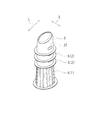
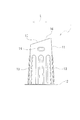
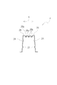
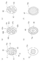
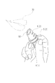
以下、本発明の一実施形態に係る簡易棒状化粧品としての簡易口紅化粧品とそれに用いられる用具について図1〜図34を参酌しつつ説明する。図1に示す簡易口紅化粧品は、化粧料である口紅化粧料50を用具本体の上面に少量付着させたものである。口紅化粧料50の付着量は種々であってよいが、例えば、一回あるいは数回塗ることができる程度の量とすることができる。簡易口紅化粧品は、例えば、一回あるいは数回使用可能な使い捨てを前提とした専用の試供品であってもよいし、長期使用可能な口紅の本品に対してそれよりも使用回数が少なく、従って口紅化粧料50の量も少ない、簡易で安価な口紅化粧品として販売されるものであってもよい。 Hereinafter, a simple lipstick cosmetic as a simple stick-shaped cosmetic according to an embodiment of the present invention and a tool used therefor will be described with reference to FIGS. The simple lipstick cosmetic shown in FIG. 1 is obtained by attaching a small amount of lipstick cosmetic 50, which is a cosmetic, to the upper surface of the tool body. The adhesion amount of the lipstick cosmetic 50 may be various, but may be an amount that can be applied once or several times, for example. Simple lipstick cosmetics, for example, may be a dedicated free sample that can be used once or several times, or may be used for a long period of time compared to this lipstick product, Therefore, the amount of the lipstick cosmetic 50 may be small and sold as a simple and inexpensive lipstick cosmetic.
簡易口紅化粧品用の用具は、第一の用具本体1と、第二の用具本体2と、キャップ3とから構成され、図1には第二の用具本体2を二つ使用する形態を図示しているが、この数は任意である。口紅化粧料50は、第一の用具本体1の上面と第二の用具本体2の上面にそれぞれ付着されている。図1のように用具本体が複数存在する構成では、用具本体毎に口紅化粧料50の色や種類を代えて組み合わせることができる。例えば、図1では第一の用具本体1が一つ、第二の用具本体2が二つあるので、合計三色の簡易口紅化粧品とすることができる。図1に示す簡易口紅化粧品は、第一の用具本体1に口紅化粧料50が付着された第一の化粧品本体4と、第二の用具本体2に口紅化粧料50が付着された第二の化粧品本体5と、キャップ3とから構成され、第一の化粧品本体4は一つ、第二の化粧品本体5は二つ、キャップ3は一つであるが、後述するように、これらの組み合わせは種々であってよい。
A simple lipstick cosmetic tool is composed of a
<第一の用具本体1>
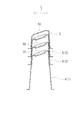
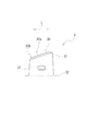
第一の用具本体1を図7〜図11に示している。該第一の用具本体1は、合成樹脂シートを熱成形して形成された成形品であって、上端閉口で下端開口の筒状である。但し、射出成形により形成された合成樹脂製の成形品であってもよい。第一の用具本体1は、天面部10と、天面部10の周縁から下方に延びる胴部11と、該胴部11の下端に、外側に向けて全周に亘って形成されたフランジ部12とを備えている。尚、第一の用具本体1は、シート成形により形成されたものであるため、外面と内面は原則として凹凸が逆の形状となり、外面に凸部が形成されていれば、それに対応した内面の位置には外面の凸部に対応した形状の凹部が形成される。尚、シート成形や材質については後述する。
<
The
<第一の用具本体1の胴部11>
胴部11は、筒状であって、その中心線は上下方向に沿っている。胴部11は、中心線を水平方向に横断する横断面視において、その横断面形状が円形ではなく第一の方向の長さが長く該第一の方向と直交する第二の方向の長さが短い非円形となっている。即ち、胴部11の横断面形状は、第一の方向を長軸方向とし第二の方向を短軸方向とする非円形となっていて、具体的には楕円形となっている。尚、図面において、長軸方向を符号L、短軸方向を符号Sで示している。
<The trunk | drum 11 of the 1st tool
The trunk | drum 11 is cylindrical, The centerline is along the up-down direction. The
胴部11は、下側に向けて徐々に拡がっていくテーパ状に形成されており、従って、上端が細く下端が太い。胴部11の上部を除く下側の領域には縦方向(上下方向)に沿ったリブ13が形成されている。該リブ13は胴部11の下端まで形成されている。該リブ13は、胴部11の外周面側に突出していて、横断面視弧状である。リブ13は周方向に間隔をあけて複数形成されることが好ましい。尚、胴部11の全長のうち、リブ13が形成されていない上側の領域とリブ13が形成されている下側の領域の長さの比率は種々であってよいが、リブ13が形成されている下側の領域の方が、リブ13が形成されていない上側の領域よりも長いことが好ましい。
The trunk | drum 11 is formed in the taper shape which expands gradually toward a lower side, Therefore, an upper end is thin and a lower end is thick.
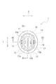
胴部11の外周面のうちリブ13が形成されていない上側の領域には、係合凹部14が形成されている。尚、第一の用具本体1はシート成形により形成されているので、外周面に係合凹部14が形成されることに伴ってそれに対応した内周面の位置には、外周面の係合凹部14に対応した形状の凸部が形成される。係合凹部14は、短軸方向に対向して一対形成されている。両係合凹部14は、互いに同一のものであって、同じ高さに位置しており、図9のように短軸上に位置していて180度対向した位置関係にある。係合凹部14は、図8のように横方向(水平方向)に沿って長い長円形状(トラック形状)に形成されている。また、係合凹部14は、図10のように縦方向(上下方向)に切断した縦断面視において円弧状である。かかる第一の用具本体1の係合凹部14には、後述するように、第二の用具本体2の係合凸部27やキャップ3の係合凸部37が係合する。
An
<第一の用具本体1の天面部10>
胴部11の上端に天面部10が位置する。胴部11が横断面視楕円形であるため、天面部10も平面視において楕円形である。即ち、天面部10を水平面に投影したときの形状は胴部11の上端における横断面形状と同じであって楕円形である。また、天面部10は、水平ではなく所定方向に傾斜している。天面部10の傾斜方向は、楕円形の長軸方向である。尚、天面部10の水平面に対する傾斜角度は任意であるが、本物の口紅化粧料50の上端の傾斜角度に合わせることが好ましく、具体的には10〜30度程度である。天面部10の上面が第一の用具本体1の上面となり、天面部10が長軸方向に傾斜していることから、第一の用具本体1の上面もまた長軸方向に傾斜している。天面部10が平面視において楕円形であって、更に、天面部10が長軸方向に傾斜していることから、天面部10をその法線方向に見ると、その長軸方向の長さは更に延長されて、より一層長軸方向に長い楕円となっている。
<The
The
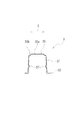
天面部10の上面に化粧料としての口紅化粧料50が付着される。従って、天面部10の上面に口紅化粧料50を付着するための部分である付着部を備えている。より詳細には、天面部10の上面は、付着部と該付着部の周囲に形成された環状の土手部16とから構成されている。付着部は、ベース面15aと、該ベース面15aに凹設された凹溝15bとからなる。ベース面15aは、楕円形であって、土手部16よりも一段低くなっている。ベース面15aは凹面であってもよいが平面とされており、天面部10が傾斜していることから、ベース面15aは傾斜平面となっている。凹溝15bは長軸方向に沿って延びていて、その深さは一定である。凹溝15bの本数は任意であるが、本実施形態では互いに平行に三本形成されており、中央の凹溝15bが長く、その両側の凹溝15bは何れも短い。また、凹溝15bの横断面形状は図10のように矩形であって底面まで幅略一定である。尚、三本の凹溝15bの深さは互いに同じになっているが互いに異なっていてもよく、例えば、中央の凹溝15bが深く、両側の凹溝15bがそれよりも浅くしてもよい。かかる付着部の周囲に土手部16が突設されており、土手部16が天面部10の上面の周縁部を構成している。尚、図10及び図11のように、土手部16のベース面15aからの突出量と凹溝15bの深さとを比較したとき、凹溝15bの深さの方が大きいことが好ましい。
A lipstick cosmetic 50 as a cosmetic is attached to the upper surface of the
<付着部の他の形態>
尚、付着部の形態、特に、ベース面15aに設ける凹部の形態は種々であってよく、上述したような長軸方向に沿った凹溝15bを設ける他、例えば、図22に示すような種々の凹部であってもよい。尚、図22において凹部にはハッチングを施している。例えば、図22(a)のように、長軸方向に沿った凹溝60と、短軸方向に沿った凹溝61とを設けて、長軸方向の凹溝60と短軸方向の凹溝61とが直角に交差する構成としてもよい。また、図22(b)のように、長軸方向に対して左右両側にそれぞれ所定角度傾斜した方向に沿った凹溝62a,62b同士を交差させる構成としてもよい。図22(c)のように、長軸方向に対して左右何れかの方向に所定角度傾斜した凹溝63のみを設けるようにしてもよい。また、所定方向に延びた凹溝ではなく、図22(d)のようにベース面15aの中央部に矩形等の所定形状の凹部64を形成してもよい。図22(e)のように、ベース面15aの中央部に所定形状、例えば楕円形の小型の凹部65を形成すると共に、その外側に間隔をあけて環状、具体的には楕円形の環状の凹溝66を形成してもよい。また、図22(f)のように、ベース面15aの周縁部を除く大部分の領域を占める大型の凹部67を形成するようにしてもよい。尚、凹部の底面やベース面15aに細かい凹凸を形成する等してそれらの面を粗面にしてもよい。
<Other forms of adhesion part>
Note that the form of the adhering portion, particularly the form of the concave portion provided on the
<第一の用具本体1のフランジ部12>
胴部11の下端にフランジ部12が形成されている。該フランジ部12は、胴部11の下端から外側に向けて水平に延びている。フランジ部12は、板状であって、詳細には平板状であり、その下面が、第一の用具本体1を載置する際の設置面となる。該フランジ部12の形状も図9のように楕円形である。
<
A
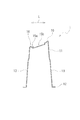
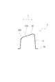
<第二の用具本体2>
第二の用具本体2を図12〜図16に示している。該第二の用具本体2も第一の用具本体1と同様に合成樹脂シートを熱成形することにより形成され、上端閉口、下端開口の筒状であって、基本構造は第一の用具本体1と同じである。但し、射出成形により形成された合成樹脂製の成形品であってもよい。第二の用具本体2も、天面部20と胴部21とフランジ部22とを備えている。以下、第一の用具本体1と同様の構成についてはその詳細な説明を省略する。
<
The 2nd tool
第二の用具本体2の胴部21は、第一の用具本体1の胴部11よりも全長(上下方向の寸法)が短い。また、第二の用具本体2の胴部21にはリブ13が形成されていないが、リブ13を形成してもよい。第二の用具本体2は、第一の用具本体1の上部に被せられる。従って、第二の用具本体2の胴部21は、第一の用具本体1の胴部11に対応した形状、寸法となっている。より詳細には、第二の用具本体2の胴部21は、第一の用具本体1の胴部11の上部の外側に嵌合するように構成されている。従って、第一の用具本体1の上側に第二の用具本体2を嵌合させると、第一の用具本体1の胴部11の外周面は、第二の用具本体2の胴部21の内周面と接触するか、あるいは、僅かな隙間を介して対峙することになる。
The
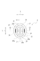
第二の用具本体2の胴部21の上部の外周面には係合凹部24が形成され、第二の用具本体2の胴部21の下部の内周面には係合凸部27が形成されている。尚、第二の用具本体2も第一の用具本体1と同様にシート成形により形成されているので、外周面に係合凹部24が形成されることに伴ってそれに対応した内周面の位置には、外周面の係合凹部24に対応した形状の凸部が形成され、また、内周面に係合凸部27が形成されることに伴ってそれに対応した外周面の位置には、内周面の係合凸部27に対応した形状の凹部が形成される。係合凹部24と係合凸部27は何れも短軸方向に対向して一対形成されており、何れも短軸上に位置している。第二の用具本体2の係合凹部24は、第一の用具本体1の係合凹部14と同様である。第二の用具本体2の係合凹部24は天面部20から所定高さ下方に位置しているが、天面部20と係合凹部24との上下方向の距離は、第一の用具本体1の天面部10と係合凹部14との間の上下方向の距離と同じに設定することが好ましい。この第二の用具本体2の係合凹部24には、キャップ3の係合凸部37が係合したり、あるいは、第二の用具本体2同士を積み重ねた際には上側に位置する第二の用具本体2の係合凸部27が係合したりする。また、第二の用具本体2の天面部20は第一の用具本体1の天面部10と同じ形状であって同じ大きさであり、その付着部や土手部26の構成も第一の用具本体1のそれらと同じであり、また、傾斜方向、傾斜角度も同じであって、ベース面25aには同様に凹溝25bが形成されている。
An engagement
<キャップ3>
キャップ3を図17〜図21に示している。キャップ3も第一の用具本体1や第二の用具本体2と同様に合成樹脂シートを熱成形することにより形成され、上端閉口、下端開口の筒状であって、基本構造は第一の用具本体1や第二の用具本体2と同じであり、天面部30と胴部31とフランジ部32とを備えている。従って、第一の用具本体1や第二の用具本体2と同様の構成についてはその詳細な説明を省略する。但し、キャップ3も射出成形により形成された合成樹脂製の成形品であってもよい。
<
The
キャップ3の胴部31の内周面には、第二の用具本体2の係合凸部27と同様の係合凸部37が形成されている。尚、キャップ3も第二の用具本体2や第一の用具本体1と同様にシート成形により形成されているので、内周面に係合凸部37が形成されることに伴ってそれに対応した外周面の位置には、内周面の係合凸部37に対応した形状の凹部が形成される。該キャップ3の係合凸部37も短軸方向に対向して一対形成されている。キャップ3の天面部30の形状は任意であって例えば指向性のない半球状等のようなドーム状であってもよいが、本実施形態では第一の用具本体1や第二の用具本体2と形状を合わせるために長軸方向に傾斜した形状となっている。尚、天面部30の上面の中央部30aは周縁部30bに対して一段上方に突出している。尚、キャップ3は、第一の用具本体1と第二の用具本体2の何れにもに被せることができる、共用のものである。従って、キャップ3の係合凸部37は、第一の用具本体1の係合凹部14にも係合でき、第二の用具本体2の係合凹部24にも係合できる。尚、キャップ3は、第一の用具本体1の上部や第二の用具本体2の上部に被せられる。従って、キャップ3の胴部31は、第一の用具本体1の胴部11の上部及び第二の用具本体2の胴部21の上部に対応した形状、寸法となっている。より詳細には、キャップ3の胴部31は、第一の用具本体1の胴部11の上部の外側に嵌合し、また、第二の用具本体2の胴部21の上部の外側に嵌合する。従って、第一の用具本体1の上側にキャップ3を嵌合させると、第一の用具本体1の胴部11の外周面は、キャップ3の胴部31の内周面と接触するか、あるいは、僅かな隙間を介して対峙することになる。同様に、第二の用具本体2の上側にキャップ3を嵌合させると、第二の用具本体2の胴部21の外周面は、キャップ3の胴部31の内周面と接触するか、あるいは、僅かな隙間を介して対峙することになる。
On the inner peripheral surface of the
尚、キャップ3は、その天面部30が第一の用具本体1の天面部10や第二の用具本体2の天面部20と同じ向きとなるように、より詳細にはキャップ3の天面部30が第一の用具本体1の天面部10や第二の用具本体2の天面部20と平行となるように被せる必要がある。天面部30の長軸方向の低い側を前側、高い側を後側としたとき、キャップ3の前後を反対にして第一の用具本体1等に被せても所定位置まで被せることができない構成となっている。例えば、図23にキャップ3を第一の用具本体1に前後逆向きで被せて、キャップ3の係合凸部37を第一の用具本体1の係合凹部14に係合させたと仮定した場合を図示している。この図23のように、キャップ3の向きが第一の用具本体1に対して前後逆向きであると、第一の用具本体1の天面部10の後側の部分である上部にキャップ3の天面部30の前側の部分である下部が当接して互いに干渉することになる。即ち、キャップ3の前後の向きが正しくない場合には、キャップ3の係合凸部37が第一の用具本体1の係合凹部14に係合する所定位置まで、キャップ3を第一の用具本体1に被せることはできない。第二の用具本体2に対しても同様であって前後同じ向きのみでキャップ3を被せることができる。
More specifically, the
<係合凹部14,24と係合凸部27,37の関係>
係合凹部14,24と係合凸部27,37は、上側の部材を下側の部材に被せた際に上側の部材を下側の部材の上下方向の所定位置に係止するための係止部を構成している。
<Relationship between engaging
The engaging
尚、係合凹部14,24の凹み量に対して係合凸部27,37の突出量の方が大きい。具体的には、第一の用具本体1の係合凹部14の凹み量よりも第二の用具本体2の係合凸部27の突出量の方が大きい。換言すれば、第一の用具本体1の係合凹部14の凹み量は第二の用具本体2の係合凸部27の突出量よりも小さい。係合凹部14,24の凹み量と係合凸部27,37の突出量との差は種々設定できるが、例えば、0.1〜0.2mmとすることができる。第二の用具本体2を第一の用具本体1に嵌合させて第二の用具本体2の係合凸部27を第一の用具本体1の係合凹部14に係合させると、図5のように、第一の用具本体1の係合凹部14に第二の用具本体2の係合凸部27が接触する一方、その周辺においては、第一の用具本体1の胴部11の外周面に対して第二の用具本体2の胴部21の内周面は僅かに離間して両者の間に隙間が形成される。このような関係は他の係合凹部24と係合凸部37との間においても同様である。従って、第一の用具本体1の係合凹部14とキャップ3の係合凸部37との間や、第二の用具本体2の係合凹部24とキャップ3の係合凸部37との間においても同様である。また、第二の用具本体2同士の間においても同様の関係があり、第二の用具本体2の係合凹部24の凹み量は第二の用具本体2の係合凸部27の突出量よりも小さい。
In addition, the protrusion amount of the engagement
<シート成形と材質>
第一の用具本体1、第二の用具本体2、及び、キャップ3は何れもシート成形により形成されている。シート成形としては例えば真空成形、圧空成形、真空圧空成形、両面真空成形、熱板成形等があり、何れにしても合成樹脂製のシートを熱成形することにより形成される。合成樹脂製のシートは、シート成形可能なものであればよく、種々の熱可塑性樹脂シートが使用できる。例えば、ポリエチレンテレフタレート樹脂等のポリエステル系樹脂や、ポリスチレンのスチレン系樹脂、ポリプロピレンやポリエチレン等のポリオレフィン系樹脂、ポリカーボネート樹脂等からなるシートである。特に、A−PET(アモルファス−ポリエチレンテレフタレート)のシートが好ましい。また、これらのシートを延伸させた延伸シートであってもよい。尚、シートは透明であっても不透明であってもよく、また、無色であっても有色であってもよい。有色の場合、有色透明であってもよく、無色透明であってもよい。上側に被せる部材、例えばキャップ3等に透明なシートを使用すると、被せられる側の部材に付着された口紅化粧料50を容易に視認でき、特に、無色透明とすることにより、口紅化粧料50の色合いを正確に把握できる。また、例えば、第一の用具本体1を黒色等の有色不透明として実物に近づけるようにしてもよい。尚、シートの厚さも種々であってよいが、例えば、0.3mm〜0.7mmのものが好ましい。このように合成樹脂シートから熱成形により形成すると、低コストに製造することができ、且つ、軽量化も容易である。また、横断面形状が楕円形であるので、横断面形状が円形の場合に比して容易にシート成形でき、高い精度を確保できる。特に、第一の用具本体1のように胴部11が長い深絞りのものである場合には、横断面形状を楕円形等の非円形にすることで成形が容易になる。
<Sheet molding and material>
The
<口紅化粧料50の付着工程>
以上のように構成された第一の用具本体1の上面や第二の用具本体2の上面には化粧料としての口紅化粧料50が付着される。一例として第一の用具本体1に口紅化粧料50を付着させる工程の概要について説明する。口紅化粧料50を付着させる際には、図24(a)のように傾斜している天面部10が水平になるように第一の用具本体1を長軸方向に傾斜させる。そして、加熱して軟化させて所定粘度の液状とした口紅化粧料50を上方から天面部10に向けて所定量垂らす。口紅化粧料50の付着量は、図24(b)のように土手部16よりも口紅化粧料50が所定量突出する程度とする。
<Adhesion process of lipstick cosmetic 50>
A lipstick cosmetic 50 as a cosmetic is attached to the upper surface of the
このように第一の用具本体1を傾斜させて天面部10を水平にすることで、口紅化粧料50を均一の厚さに付着させることができる。また、口紅化粧料50の中央部を盛り上げるようにすることもできる。そして、天面部10の付着部に凹溝15bが形成されているので、口紅化粧料50の密着性を高めることができる。特に、凹溝15bが長軸方向に沿って延びているので、液状の口紅化粧料50が凹溝15bに沿って長軸方向に流れやすく、長軸方向の両端部まで口紅化粧料50が広がっていく。即ち、長軸方向の凹溝15bによって、液状の口紅化粧料50の流動性は短軸方向よりも長軸方向の方が良好となる。従って、付着部が円形ではなく楕円形であっても中央部に口紅化粧料50を垂らすことで周縁部までスムーズに口紅化粧料50が広がる。また、付着部の周囲に土手部16を突設しているので、口紅化粧料50が天面部10の周縁から下方に流れ落ちることも防止できる。土手部16を設けることで、口紅化粧品の本品に近い形状に口紅化粧料50を付着させることができる。更に、口紅化粧料50の付着量や厚さを容易にコントロールすることができ、例えば、付着部の中央部と周縁部における口紅化粧料50の厚さの差を小さくして口紅化粧料50を平坦にすることもでき、また、口紅化粧料50の中央部が盛り上がるようにすることもできる。
Thus, the lipstick cosmetic 50 can be made to adhere to a uniform thickness by inclining the
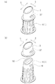
<簡易口紅化粧品の使用方法>
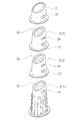
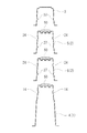
例えば、図1に示した簡易口紅化粧品は、下側から順に、第一の用具本体1を使用した一つの第一の化粧品本体4と、第二の用具本体2を使用した二つの第二の化粧品本体5と、一つのキャップ3とから構成されている。これらは順に第一の化粧品本体4の上に第二の化粧品本体5、第二の化粧品本体5の上にキャップ3というようにして積み重ねていけばよい。第二の用具本体2の全長が短いので、第一の化粧品本体4の上に第二の化粧品本体5を積み重ねても簡易口紅化粧品全体の全長を抑制できる。また、第一の用具本体1、第二の用具本体2、及びキャップ3が何れも下端開口の筒状であって下広がりのテーパ形状であるので、それらを容易に被せて積み重ねることができる。しかも、それらの部材の下端にはフランジ部12が形成されているので、各部材の下端の強度を容易に確保できる。
<How to use simple lipstick cosmetics>
For example, the simple lipstick cosmetic shown in FIG. 1 has, in order from the bottom, one first
また、下側の部材の係合凹部14,24に上側の部材の係合凸部27,37が係合するので、各部材を所定の高さに確実に停止させることができ、上側の部材が所定位置を下側に越えて深く被せられるということを防止できる。そして、図3や図4のように、下側の部材の口紅化粧料50と上側の部材の天面部10,20,30との間には所定の間隙が確保される。従って、下側の部材の口紅化粧料50に上側の部材の天面部10,20,30が付着するということが防止される。また逆に、上側の部材を下側の部材に所定位置に達しない程度に浅く被せたりするということも防止できる。従って、不用意にキャップ3等が外れ落ちるということがない。そして、係合凹部14,24と係合凸部27,37によって部材の揺動も防止されるので、安定した積み重ね状態が得られる。
Further, since the engaging
尚、第一の化粧品本体4の上に第二の化粧品本体5を被せた際に、第二の用具本体2のフランジ部22が第一の用具本体1のリブ13に当たらないように、第二の用具本体2のフランジ部22が第一の用具本体1のリブ13の上端よりも上側に位置することが好ましい。第一の化粧品本体4の上にキャップ3を被せた際も同様であって、キャップ3のフランジ部32が第一の用具本体1のリブ13に当たらないように、キャップ3のフランジ部32が第一の用具本体1のリブ13の上端よりも上側に位置することが好ましい。
In order to prevent the
また、第一の化粧品本体4の上に第二の化粧品本体5を被せた際に、第二の用具本体2の胴部21の全長のうち短軸上の位置において下側の1/3〜2/3の部分が第一の用具本体1の胴部11に被さることが好ましく、下側の1/2〜2/3の部分が第一の用具本体1の胴部11に被さることが更に好ましい。第二の化粧品本体5同士を積み重ねる場合も同様であって、上側の第二の用具本体2の胴部21の全長のうち短軸上の位置において下側の1/3〜2/3の部分が下側の第二の用具本体2の胴部21に被さることが好ましく、下側の1/2〜2/3の部分が下側の第二の用具本体2の胴部21に被さることが更に好ましい。
Further, when the second
第一の用具本体1、第二の用具本体2、及びキャップ3は何れも横断面形状が円形ではなく楕円形であるので、下側の部材に上側の部材を被せると、上側の部材の長軸方向と下側の部材の長軸方向が自動的に一致する。従って、部材同士の周方向の向きを容易に揃えて積み重ねることができる。また、係合凹部14,24や係合凸部27,37は180度対向して一対形成されているので、部材同士の周方向の位置を正確に調整しなくても、下側の部材の係合凹部14,24に上側の部材の係合凸部27,37を容易に係合させることができる。
Since the
また、キャップ3を備えているので、口紅化粧料50の露出を防止でき、口紅化粧料50を保護することができる。同様に、第二の用具本体2も下側の口紅化粧料50を保護する。従って、口紅化粧料50が露出しないので携帯性に優れ、特に店頭から持ち帰る場合に好適である。
Moreover, since the
尚、係合凸部27,37が縦断面視円弧状であるので、例えばキャップ3を第二の化粧品本体5に被せていく際に、キャップ3の係合凸部37が第二の用具本体2の胴部21の外周面をスムーズに下方に向けて摺動することになり、キャップ3の装着がスムーズになる。一方、係合凹部14、24や係合凸部27、37が横長の長円形状であるので、例えば円形状である場合に比して大きな係止力が得られる。曲率半径が大きい短軸上に係合凹部14、24や係合凸部27、37を形成しているので、長円形状の横寸法を容易に確保できる。
In addition, since the engagement
更に、係合凹部14,24の凹み量よりも係合凸部27,37の突出量の方が大きいので、例えば、第一の用具本体1の係合凹部14に第二の用具本体2の係合凸部27が係合した状態において、第一の用具本体1の胴部11の外周面と第二の用具本体2の胴部21の内周面との接触面積が小さくなり、第二の用具本体2を第一の用具本体1にスムーズに着脱できる。
Furthermore, since the protruding amount of the engaging
また、係合凹部14,24と係合凸部27,37は何れも短軸上に位置しているので、長軸上に形成する場合に比して、容易に形成できる。しかも、胴部11,21,31において短軸方向に対向した部分は、長軸方向に対向した部分に比して曲率半径が大きいため、内外方向に変形しやすく、従って、係合凹部14,24に係合凸部27,37を係合させやすい。更に、係合凹部14,24や係合凸部27,37を短軸上に形成すると、上面から係合凹部14,24や係合凸部27,37までの距離が左右等しくなり、スムーズに係合させることができる。
Further, since the engaging
使用に際しては、図1のようなキャップ3を被せた状態から、図25に示すようにキャップ3を外して上側の第二の化粧品本体5の口紅化粧料50を露出させる。キャップ3の下端にはフランジ部32が形成されているので、キャップ3のフランジ部32に指先を引っ掛けてキャップ3を第二の化粧品本体5から容易に外すことができる。キャップ3を外した後、第一の化粧品本体4の上側に二つの第二の化粧品本体5を積み重ねた状態のままで、それらをまとめて掴んで、最上段に位置している上側の第二の化粧品本体5の口紅化粧料50を唇70に塗ることができる。第二の化粧品本体5は第一の化粧品本体4よりも短いので、第一の化粧品本体4の上に第二の化粧品本体5を積み重ねても全体の全長を抑制することができ、積み重ねた状態であっても、それらをまとめて掴みやすい。また、第二の化粧品本体5を単独で使用することもできるが、単独で使用する場合よりも全長が長くなり、掴みやすくなるうえに、口紅化粧品の本品の長さにも近くなる。使用者の好みにもよるが、全長が長い方を好む場合には、第二の化粧品本体5を単独ではなく積み重ねて使用すればよい。尚、口紅化粧料50を塗る際には短軸方向に簡易口紅化粧品を移動させることになるが、係合凹部14,24や係合凸部27,37は短軸上に位置しているので、第二の化粧品本体5の短軸方向の揺動を抑制することができる。従って、第一の化粧品本体4の上に第二の化粧品本体5を積み重ねた状態であっても、安定した状態で第二の化粧品本体5の口紅化粧料50を唇70に塗ることができる。
In use, from the state of covering the
また、付着部には長軸方向に沿って凹溝15b,25bが形成されているので、該凹溝15b,25bに入り込んだ口紅化粧料50の部分がアンカー機能を発揮し、口紅化粧料50を塗る際に、口紅化粧料50が付着部から短軸方向に位置ずれしたり、あるいは、付着部から外れ落ちたりすることを防止できる。尚、付着部の周囲には土手部16,26が形成されているので、該土手部16,26によっても口紅化粧料50の位置ずれを防止できる。
Further, since the
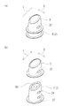
更に、図26のように上側の第二の化粧品本体5を取り外せば、下側の第二の化粧品本体5の口紅化粧料50を露出させることができ、同様にそれを唇70に塗ることができる。更に、図2のように下側の第二の化粧品本体5も取り外せば、第一の化粧品本体4の口紅化粧料50を露出させることができ、その口紅化粧料50を塗ることができる。仮に、それぞれの口紅化粧料50が異なる色であれば三色それぞれの色合いを試したりする等、使用することができる。尚、図2のようにキャップ3、二つの第二の化粧品本体5、第一の化粧品本体4を全て分離してもよいが、例えば、キャップ3と二つの第二の化粧品本体5をまとめて第一の化粧品本体4から分離して、第一の化粧品本体4を使用してもよい。このように第二の化粧品本体5等を分離する際にもその下端にフランジ部22が形成されているので、そこに指先を引っ掛けて容易に分離できる。また、分離した単体の状態であっても、各部材の下端にはそれぞれフランジ部12,22,32が形成されているので、各部材の下端の強度を容易に確保でき、それらを掴んでも変形しにくい。特に、第一の化粧品本体4や第二の化粧品本体5においてはそれらを掴んだときに変形しにくいので、口紅化粧料50を安定して塗ることができる。また、分離する際や装着する際にフランジ部12,22,32の外縁を内外方向に掴むと、胴部11,22の外周面を掴む場合に比して、指先が口紅化粧料50から径方向外側に離れるので、指先に口紅化粧料50が付きにくくなる。
Further, if the upper second
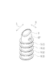
尚、上述したように、第一の化粧品本体4、第二の化粧品本体5はそれぞれ単独で使用でき、また、それらにキャップ3を被せて単色用の簡易口紅化粧品とすることもできる。図27(a)は第一の化粧品本体4にキャップ3を被せた状態で、図27(b)は同じくキャップ3を外した状態であるが、このように第一の化粧品本体4とキャップ3とを備えた簡易口紅化粧品としてもよい。図28(a)は第二の化粧品本体5にキャップ3を被せた状態で、図28(b)は同じくキャップ3を外した状態であるが、このように第二の化粧品本体5とキャップ3とを備えた簡易口紅化粧品としてもよい。また、図29のように第二の化粧品本体5のみを複数、具体的には四つ積み重ねてキャップ3を被せて多色用の簡易口紅化粧品としてもよい。このように種々の組み合わせ方ができる。
As described above, the first cosmetic
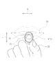
次に、簡易口紅化粧品を使用して口紅化粧料50を唇70に塗る動作を更に詳細に述べる。まず、簡易口紅化粧品の持ち方であるが、これは使用者の好みに応じて種々の持ち方であってよいが、代表的な二種類の持ち方について第一の化粧品本体4のみを持つ場合を例にして説明する。図30に第一の化粧品本体4を使用して口紅化粧料50を塗る様子を図示している。この場合、第一の用具本体1の胴部11の外周面を把持している。第一の用具本体1の胴部11の外周面の横断面形状が楕円形となっているので、第一の用具本体1の胴部11の外周面を掴むと、第一の用具本体1の楕円形が視覚のみならず触覚によっても容易に把握することができる。そして、第一の用具本体1の上面の傾斜方向、即ち、口紅化粧料50の傾斜方向が、第一の用具本体1の長軸方向と一致しているので、その長軸方向が前後方向あるいは上下方向となるように第一の用具本体1の胴部11の外周面を掴むことにより、口紅化粧料50の向きを唇70に容易に合わせることができる。
Next, the operation of applying the lipstick cosmetic 50 to the
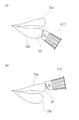
そして、第一の用具本体1の上面に付着された口紅化粧料50も楕円形となっているので、図34(a)のように、付着された口紅化粧料50の長軸方向の長さを利用して下唇70bを効率良く塗ることができる。即ち、太い口紅化粧品を用いた場合と同様に、下唇70bの広い面積を効率良く塗ることができる。また、口紅化粧料50が楕円形であるので、口紅化粧料50が細い円形の場合とは異なり、口紅化粧料50の量も十分に確保されており、従って、口紅化粧料50の量が不足することもない。一方、図34(b)のように口紅化粧料50の長軸方向の両端部のうちの一方である上部を上唇70aの上縁に当てるようにして上唇70aの輪郭を正確に描くことができる。即ち、細い口紅化粧品を用いた場合と同様に細かい部分を容易且つ正確に塗ることができる。このように、一本の第一の化粧品本体4で細い口紅化粧品と太い口紅化粧品の両方の使用感が得られる。
Since the lipstick cosmetic 50 attached to the upper surface of the
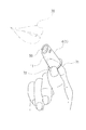
また、第一の用具本体1は下端開口の筒状であるため、その下端の開口部から第一の用具本体1の内側に指先を挿入して第一の用具本体1の胴部11を掴むこともできる。例えば、図32や図33に示すように人差し指71を第一の用具本体1の内側に差し込んで親指72と共に第一の用具本体1の胴部11を掴んで保持するということもできる。この持ち方の場合も第一の用具本体1の胴部11が楕円形であるので、第一の用具本体1の向きを簡単に把握することができ、上面の口紅化粧料50の向きを唇70に容易に合わせることができる。尚、第一の化粧品本体4を例に説明したが、第二の化粧品本体5についても同様である。
Further, since the
また、図31に示すように、第一の化粧品本体4に二つの第二の化粧品本体5を積み重ねて使用する場合も、同様に第一の化粧品本体4や第二の化粧品本体5の外側を把持するようにして持つことができ、また、図示しないが、第一の用具本体1の内側に人差し指71等を入れて、第一の化粧品本体4と第二の化粧品本体5とをまとめて持つこともできる。
In addition, as shown in FIG. 31, when two second
尚、本実施形態では、第一の用具本体1や第二の用具本体2を中空状としたが中実状のものであってもよい。但し、中空状とすることにより容易に軽量化でき、低コストに製造することもできる。また、中空状とする場合、射出成形で形成してもよいが、合成樹脂シートから熱成形により形成することが好ましく、より一層低コストに製造することができる。また、大小二種類の用具本体を備える構成について説明したが、三種類以上であってもよいし、一種類のみであってもよい。
In the present embodiment, the
1 第一の用具本体
2 第二の用具本体
3 キャップ
4 第一の化粧品本体
5 第二の化粧品本体
10 天面部
11 胴部
12 フランジ部
13 リブ
14 係合凹部
15a ベース面
15b 凹溝
16 土手部
20 天面部
21 胴部
22 フランジ部
24 係合凹部
25a ベース面
25b 凹溝
26 土手部
27 係合凸部
30 天面部
30a 中央部
30b 周縁部
31 胴部
32 フランジ部
37 係合凸部
50 口紅化粧料
60 凹溝
61 凹溝
62a 凹溝
62b 凹溝
63 凹溝
64 凹部
65 凹部
66 凹溝
67 凹部
70 唇
70a 上唇
70b 下唇
71 人差し指
72 親指
DESCRIPTION OF
Claims (13)
用具本体の上面は、所定方向に傾斜しており、
用具本体の外周面の横断面形状は、第一の方向を長軸方向とし該第一の方向と直交する第二の方向を短軸方向とする非円形であり、
用具本体の上面の傾斜方向は、用具本体の外周面の長軸方向である
ことを特徴とする簡易棒状化粧品用の用具。 A tool for a simple stick-shaped cosmetic provided with a tool body on which cosmetics are attached to the upper surface,
The upper surface of the tool body is inclined in a predetermined direction,
The cross-sectional shape of the outer peripheral surface of the tool body is a non-circular shape in which the first direction is the major axis direction and the second direction perpendicular to the first direction is the minor axis direction,
A tool for simple bar-shaped cosmetics, wherein the direction of inclination of the upper surface of the tool body is the major axis direction of the outer peripheral surface of the tool body.
第一の用具本体の上部の外周面に係合凹部が形成され、
第二の用具本体の上部の外周面に係合凹部が形成され、第二の用具本体の下部の内周面に係合凸部が形成され、
第一の用具本体の上側に第二の用具本体を被せると共に該第二の用具本体の上側にキャップを被せた際に、第一の用具本体の係合凹部に第二の用具本体の係合凸部が係合し、且つ、第二の用具本体の係合凹部にキャップの係合凸部が係合する請求項5乃至8の何れかに記載の簡易棒状化粧品用の用具。 A first tool body, and a second tool body having a shorter vertical length than the first tool body, the upper part of the first tool body being covered with the lower part of the second tool body. Can
An engagement recess is formed on the outer peripheral surface of the upper part of the first tool body,
An engaging recess is formed on the outer peripheral surface of the upper part of the second tool body, and an engaging convex part is formed on the inner peripheral surface of the lower part of the second tool body,
When the second tool body is put on the upper side of the first tool body and the cap is put on the upper side of the second tool body, the second tool body is engaged with the engaging recess of the first tool body. The tool for a simple bar-shaped cosmetic product according to any one of claims 5 to 8, wherein the convex portion is engaged, and the engaging convex portion of the cap is engaged with the engaging concave portion of the second tool body.
Priority Applications (1)
| Application Number | Priority Date | Filing Date | Title |
|---|---|---|---|
| JP2015122133A JP6587339B2 (en) | 2015-06-17 | 2015-06-17 | Simple bar-shaped cosmetics and simple bar-shaped cosmetics |
Applications Claiming Priority (1)
| Application Number | Priority Date | Filing Date | Title |
|---|---|---|---|
| JP2015122133A JP6587339B2 (en) | 2015-06-17 | 2015-06-17 | Simple bar-shaped cosmetics and simple bar-shaped cosmetics |
Related Child Applications (1)
| Application Number | Title | Priority Date | Filing Date |
|---|---|---|---|
| JP2019098272A Division JP6746190B2 (en) | 2019-05-27 | 2019-05-27 | Tools for simple stick cosmetics and simple stick cosmetics |
Publications (2)
| Publication Number | Publication Date |
|---|---|
| JP2017006202A true JP2017006202A (en) | 2017-01-12 |
| JP6587339B2 JP6587339B2 (en) | 2019-10-09 |
Family
ID=57760576
Family Applications (1)
| Application Number | Title | Priority Date | Filing Date |
|---|---|---|---|
| JP2015122133A Expired - Fee Related JP6587339B2 (en) | 2015-06-17 | 2015-06-17 | Simple bar-shaped cosmetics and simple bar-shaped cosmetics |
Country Status (1)
| Country | Link |
|---|---|
| JP (1) | JP6587339B2 (en) |
Cited By (1)
| Publication number | Priority date | Publication date | Assignee | Title |
|---|---|---|---|---|
| JP2019013621A (en) * | 2017-07-10 | 2019-01-31 | 紀伊産業株式会社 | Rod-like cosmetic container |
Citations (5)
| Publication number | Priority date | Publication date | Assignee | Title |
|---|---|---|---|---|
| JPS61137981U (en) * | 1985-02-16 | 1986-08-27 | ||
| JPH0975132A (en) * | 1995-09-08 | 1997-03-25 | Shiseido Co Ltd | Bar-shaped cosmetic material letting-out container |
| JP2005503198A (en) * | 2001-06-14 | 2005-02-03 | カラー アクセス,インコーポレイティド | Flocked cosmetic sampler and its production and use |
| JP2006158777A (en) * | 2004-12-09 | 2006-06-22 | Shiseido Co Ltd | Stick-shaped cosmetic dispensing container |
| JP2013176683A (en) * | 2013-06-21 | 2013-09-09 | Kao Corp | Lip cosmetics applicator |
-
2015
- 2015-06-17 JP JP2015122133A patent/JP6587339B2/en not_active Expired - Fee Related
Patent Citations (5)
| Publication number | Priority date | Publication date | Assignee | Title |
|---|---|---|---|---|
| JPS61137981U (en) * | 1985-02-16 | 1986-08-27 | ||
| JPH0975132A (en) * | 1995-09-08 | 1997-03-25 | Shiseido Co Ltd | Bar-shaped cosmetic material letting-out container |
| JP2005503198A (en) * | 2001-06-14 | 2005-02-03 | カラー アクセス,インコーポレイティド | Flocked cosmetic sampler and its production and use |
| JP2006158777A (en) * | 2004-12-09 | 2006-06-22 | Shiseido Co Ltd | Stick-shaped cosmetic dispensing container |
| JP2013176683A (en) * | 2013-06-21 | 2013-09-09 | Kao Corp | Lip cosmetics applicator |
Cited By (1)
| Publication number | Priority date | Publication date | Assignee | Title |
|---|---|---|---|---|
| JP2019013621A (en) * | 2017-07-10 | 2019-01-31 | 紀伊産業株式会社 | Rod-like cosmetic container |
Also Published As
| Publication number | Publication date |
|---|---|
| JP6587339B2 (en) | 2019-10-09 |
Similar Documents
| Publication | Publication Date | Title |
|---|---|---|
| USD788372S1 (en) | Multi-color face and body paint container | |
| USD837507S1 (en) | Combination key ring and fragrance dispenser | |
| JP6746190B2 (en) | Tools for simple stick cosmetics and simple stick cosmetics | |
| USD834305S1 (en) | Combination key ring and fragrance dispenser | |
| JP2017522997A (en) | Razor handle with components in the hole and a razor with such a razor handle | |
| USD834306S1 (en) | Combination key ring and fragrance dispenser | |
| US20160015101A1 (en) | Grid of fasteners with removable and interchangeable decorative modular tiles for use with accessories and apparel items | |
| JP6587339B2 (en) | Simple bar-shaped cosmetics and simple bar-shaped cosmetics | |
| USD837508S1 (en) | Combination key ring and fragrance dispenser | |
| USD834304S1 (en) | Combination key ring and fragrance dispenser | |
| USD834307S1 (en) | Combination key ring and fragrance dispenser | |
| US20170333285A1 (en) | Medication vial covers | |
| CN104918523A (en) | Serving tray | |
| JP2021513490A (en) | Grip attachment for bottles | |
| WO2020244436A1 (en) | Measuring cup lid structure based on double injection molding and injection stretch blow molding | |
| US20200383461A1 (en) | Cosmetics brush with reservoir | |
| USD935050S1 (en) | Allergen dropper bottle | |
| US9609937B1 (en) | Eye lid protector and eye make-up protector | |
| KR102328183B1 (en) | Puff | |
| KR101917332B1 (en) | Lipstick case | |
| JP5893483B2 (en) | Squeeze container | |
| US20150044427A1 (en) | Label | |
| JP2015214086A (en) | Finger sack and method for manufacturing the same | |
| USD994771S1 (en) | Writing instrument | |
| JP7391471B2 (en) | Friction tools and thermochromic writing tools |
Legal Events
| Date | Code | Title | Description |
|---|---|---|---|
| A621 | Written request for application examination |
Free format text: JAPANESE INTERMEDIATE CODE: A621 Effective date: 20180424 |
|
| A977 | Report on retrieval |
Free format text: JAPANESE INTERMEDIATE CODE: A971007 Effective date: 20190412 |
|
| A131 | Notification of reasons for refusal |
Free format text: JAPANESE INTERMEDIATE CODE: A131 Effective date: 20190419 |
|
| A521 | Request for written amendment filed |
Free format text: JAPANESE INTERMEDIATE CODE: A523 Effective date: 20190527 |
|
| TRDD | Decision of grant or rejection written | ||
| A01 | Written decision to grant a patent or to grant a registration (utility model) |
Free format text: JAPANESE INTERMEDIATE CODE: A01 Effective date: 20190906 |
|
| A61 | First payment of annual fees (during grant procedure) |
Free format text: JAPANESE INTERMEDIATE CODE: A61 Effective date: 20190909 |
|
| R150 | Certificate of patent or registration of utility model |
Ref document number: 6587339 Country of ref document: JP Free format text: JAPANESE INTERMEDIATE CODE: R150 |
|
| R250 | Receipt of annual fees |
Free format text: JAPANESE INTERMEDIATE CODE: R250 |
|
| LAPS | Cancellation because of no payment of annual fees |