JP2017005481A - Imaging apparatus - Google Patents
Imaging apparatus Download PDFInfo
- Publication number
- JP2017005481A JP2017005481A JP2015117039A JP2015117039A JP2017005481A JP 2017005481 A JP2017005481 A JP 2017005481A JP 2015117039 A JP2015117039 A JP 2015117039A JP 2015117039 A JP2015117039 A JP 2015117039A JP 2017005481 A JP2017005481 A JP 2017005481A
- Authority
- JP
- Japan
- Prior art keywords
- unit
- drive
- imaging
- driving
- correction
- Prior art date
- Legal status (The legal status is an assumption and is not a legal conclusion. Google has not performed a legal analysis and makes no representation as to the accuracy of the status listed.)
- Granted
Links
Images


Abstract
Description
本発明は、撮像装置に関し、特に、撮像光学系の駆動手段を備える撮像装置に関する。 The present invention relates to an imaging apparatus, and more particularly, to an imaging apparatus that includes a driving unit for an imaging optical system.
撮像装置において、被写体に太陽等の明るい光源が含まれている場合、その光源の光がレンズ表面、レンズを保持する構造物、撮像素子の表面等で反射し、その反射光の像が撮像素子上にゴーストとして結像することがある。このゴーストによる被写体像への影響を軽減させるために、ゴーストを低減または検出する技術が知られている。 In the imaging apparatus, when the subject includes a bright light source such as the sun, the light from the light source is reflected by the lens surface, the structure holding the lens, the surface of the imaging device, and the image of the reflected light is the imaging device. It may be imaged as a ghost on top. In order to reduce the influence of the ghost on the subject image, a technique for reducing or detecting the ghost is known.
例えば、特許文献1では、撮像素子からの反射光によるゴースト・フレアを抑制するために、絞りばねと光学フィルタのうち少なくとも光学フィルタが光軸直行面に対して傾斜させる構成のレンズが開示されている。 For example, Patent Document 1 discloses a lens having a configuration in which at least the optical filter of the diaphragm spring and the optical filter is inclined with respect to the optical axis orthogonal surface in order to suppress ghost and flare caused by reflected light from the image sensor. Yes.
また、特許文献2では、フォーカス画像とデフォーカス画像との差分、主光源の検出、動きベクトルの要素を基に、ゴーストの検出を行う技術が開示されている。 Patent Document 2 discloses a technique for detecting a ghost based on a difference between a focus image and a defocus image, detection of a main light source, and elements of a motion vector.
しかしながら、上述の特許文献に開示された従来技術では、近年レンズが小型化していく関係で、光学フィルタ等の光学部品の搭載自由度は低下しているため、適切にゴーストの影響を低減できない場合がある。 However, in the related art disclosed in the above-mentioned patent document, since the degree of freedom of mounting optical components such as an optical filter has decreased due to the recent miniaturization of lenses, the influence of ghosts cannot be reduced appropriately. There is.
そこで、本発明の目的は、発生するゴーストによる被写体像の影響を低減することを可能にした撮像装置を提供することである。 SUMMARY OF THE INVENTION An object of the present invention is to provide an imaging apparatus that can reduce the influence of a subject image due to a generated ghost.
上記目的を達成するために、本発明は、撮像光学部を有する撮像装置であって、前記撮像光学部によって結像される被写体像を画像データに変換する撮像手段と、前記画像データにおいて高輝度領域を検知する検知手段と、前記撮像光学部または前記撮像手段のうち少なくとも一つを駆動させることができる駆動手段と、前記駆動手段を前記検知手段の検知結果に基づいて制御する駆動制御手段を備え、前記駆動制御手段は前記駆動手段による駆動量を所定の閾値以下となるように制御することを特徴とする。 In order to achieve the above object, the present invention provides an image pickup apparatus having an image pickup optical unit, an image pickup unit for converting a subject image formed by the image pickup optical unit into image data, and high brightness in the image data. Detection means for detecting an area; drive means capable of driving at least one of the imaging optical unit or the imaging means; and drive control means for controlling the drive means based on a detection result of the detection means. The drive control means controls the drive amount by the drive means so as to be a predetermined threshold value or less.
本発明によれば、発生するゴーストによる被写体像の影響を低減することを可能にした撮像装置を提供することができる。 ADVANTAGE OF THE INVENTION According to this invention, the imaging device which made it possible to reduce the influence of the to-be-photographed image by the ghost to generate | occur | produce can be provided.
以下に、本発明の好ましい実施の形態を、添付の図面に基づいて詳細に説明する。なお、以下の実施例において示す構成は一例に過ぎず、本発明は、図示された構成に限定されるものではない。 Hereinafter, preferred embodiments of the present invention will be described in detail with reference to the accompanying drawings. The configurations shown in the following embodiments are merely examples, and the present invention is not limited to the illustrated configurations.
(実施例1)
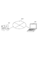
図1は、撮像装置1000を含むシステム構成図である。2000は、本発明における外部装置を示すクライアント装置である。撮像装置1000とクライアント装置2000は、ネットワーク3000を介して相互に通信可能な状態に接続されている。クライアント装置2000は、撮像装置1000に対して、各種制御コマンドを送信する。本制御コマンドには、例えば、撮像の開始・終了、撮像画像の配信開始・停止、カメラ制御等を行うためのコマンドが含まれる。また、各制御コマンドを受信した撮像装置1000は、受信した制御コマンドに対するレスポンスをクライアント装置2000に送信する。
Example 1
FIG. 1 is a system configuration diagram including an
なお、本実施例における撮像装置1000は、ネットワーク経由でクライアント装置2000と通信する通信装置の一例であり、例えば動画像を撮像する監視カメラである。より詳細には、監視に用いられるネットワークカメラであるものとする。また、本実施例におけるクライアント装置2000は、PC等の外部装置の一例である。又、本実施例における撮像装置1000と外部装置2000からなる監視システムは、撮像システムに相当する。
Note that the
また、ネットワーク3000は、例えばEthernet(登録商標)等の通信規格を満足する複数のルータ、スイッチ、ケーブル等から構成されるものとする。しかしながら、本実施例においては、撮像装置1000とクライアント装置2000との間の通信を行うことができるものであれば、その通信規格、規模、構成を問わない。
The
例えば、ネットワーク3000は、インターネットや有線LAN(Local Area Network)、無線LAN(Wireless LAN)、WAN(Wide Area Network)等により構成されていても良い。なお、本実施例における撮像装置1000は、例えば、PoE(Power Over Ethernet(登録商標))に対応していても良く、LANケーブルを介して電力を供給されても良い。
For example, the
以下に、図2を参照して本実施例に係る撮像装置1000に含まれる撮像光学系の構造について説明する。
The structure of the imaging optical system included in the
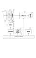
不図示の被写体像(被写体から入射する光)は、レンズ101を介して、NDフィルタやIRCFフィルタ等を含む光学フィルタ102を通して、CCDまたはCMOSセンサなどの撮像素子103に入射する。本実施例において、レンズ101及び光学フィルタ102は撮像光学部に相当する。
A subject image (not shown) (light incident from the subject) enters the
レンズ101等によって撮像素子103上に結像した被写体像は電気信号に変換され、撮像素子103内部のA/Dコンバータでデジタル信号(画像データ)に変換される。
A subject image formed on the
高輝度被写体検知部104は、変換された画像データから生成される画像内に、高輝度被写体が含まれているかどうかを検知し、その検知結果を後述するシステムコントローラ105に通知する。より詳細には高輝度被写体検知部104は、入力された画像を複数の領域に分割する。そして、各分割領域において、輝度値を算出する。ここで、算出する輝度値は領域内の輝度の平均値でもよいし、最大値でもよい。そして、算出した結果に基づいて、画像内に、高輝度被写体が含まれているかどうかの検知をおこなう。
The high brightness
システムコントローラ105は、システムを制御するCPUを含む。そして、撮像装置1000の全体を制御する。具体的には、システムコントローラ105は、各ブロックに対して、制御指示及びパラメータ等の設定を行う。また、システムコントローラ105は高輝度被写体検知部104等が検出した結果を不図示のメモリーに保存し、演算等を行い、その結果を各ブロックに出力する。メモリーは、システムコントローラ105が実行するプログラム格納領域、プログラム実行中のワーク領域、不要光発生条件等、様々なデータの格納領域として使用される。
The
駆動制御部106は、駆動部107を制御することでレンズ101、光学フィルタ102、撮像素子103等を制御する。具体的には、駆動制御部106は、駆動タイミングの生成、レンズ位置の変更、撮像素子等の傾きの制御を行う。本実施例における駆動制御部106は、高輝度被写体検知部104が高輝度被写体を検知したかどうかの通知をシステムコントローラ105から受け取る。通知された結果において、高輝度被写体が検知された場合は、駆動部107に対して光学系(101、102)または撮像素子103を駆動させるように指示を出す。本実施例において、駆動方向は、xyz軸方向及び傾きの方向のいずれにも駆動できるものを想定するが、一方向又は二方向としてもよい。
The
さらに、画像補正部108では、撮像素子103から出力された画像データに対して所定の画像補正を行う。例えば、画素の欠陥補正や色補正等を実行する。また、画像補正部108は、駆動部107によって駆動された光学系(101、102)または撮像素子103に起因する画像の劣化を補正する。
Further, the
補正された画像は、ディスプレイ等からなる表示系109へと出力される。
The corrected image is output to a
通信部110は、ネットワーク3000と接続するための機能を備え、画像補正部108から出力される画像を外部に送信したり、外部より制御信号やパラメータ設定を受け付けたりする。
The
次に、図3のフローチャートを参照して、システムコントローラ105が行う本実施例の動作処理について説明を行う。
Next, with reference to the flowchart of FIG. 3, the operation process of the present embodiment performed by the
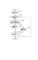
ステップS201において、システムコントローラ105は、撮像素子103を制御し、高輝度被写体検知部104に画像を入力する。そして、ステップS202に処理を進める。
In step S <b> 201, the
ステップS202において、システムコントローラ105は、高輝度被写体検知部104の検知結果を取得する。そして、画像中に高輝度被写体が存在するかどうかを判定する。判定方法の一例としては、画像中からあらかじめ定められた閾値以上の高輝度領域を検出し、さらにその領域の中で連続した領域があらかじめ定められた領域よりも大きいかどうかを判定する。その結果、図4に示したように、高輝度被写体の有無及び、高輝度画素領域として抽出することができる。判定結果として、高輝度被写体が検知されなければ、本処理を終了する。一方で、判定結果として、高輝度被写体が検知された時は、ステップS203に処理を進める。
In step S202, the
ステップS203において、システムコントローラ105は、駆動部106を制御し、光学系(101、102)または撮像素子103を駆動させる。本実施例において、駆動させる方法の一例としては、ステップS202の判定結果として高輝度被写体が検知されると、システムコントローラ105は駆動制御部106に駆動量を指定して駆動を指示する。本実施例においては撮像素子103を駆動することを想定する。指示を受けた駆動制御部106は、指示された値に従って駆動部107に動作を指示する。その結果として、撮像素子103を所定方向に傾けることができ、撮像素子103上で反射する光が再度撮像素子103に再度入射することを防ぐことができる。そして、処理をステップS204に進める。
In step S <b> 203, the
ステップS204において、システムコントローラ105は、駆動制御部106に設定した駆動量がその値が所定の閾値以下か否かの比較を行う。この閾値は、ユーザー等の設定した値であってもよい。比較結果として、駆動量が閾値以下だった場合は、処理をステップS206に進める。一方で、駆動量が閾値を上回っていた場合は、処理をステップS205に進める。
In step S204, the
ステップS205において、システムコントローラ105は、駆動量を閾値に設定して駆動制御部106に動作を指示する。そして、処理をステップS206に進める。
In step S205, the
ステップS206において、システムコントローラ105は、取得した画像を補正するために画像補正部108へあらかじめ定められた補正種類と補正係数を指示する。画像補正部108では、撮像素子103から出力された画像にたいして、システムコントローラ105の設定に基づいて補正動作を行う。なお、本実施例において、画像補正部108は撮像素子103が傾くことによって生じるフォーカスのずれを補正するためのシャープネス補正や、歪みを補正するディスト―ション補正等を実行することを想定する。だが、上記補正以外の補正を組み合わせて実行するようにしてもよい。そして、処理を終了する。
In step S206, the
上記のとおり本第1の実施例によれば、高輝度被写体を検知した時に、光学系(101、102)または撮像素子103を駆動して、ゴーストを軽減しながら画像を補正することで画像劣化を抑えた画像を実現できる。
As described above, according to the first embodiment, when a high-luminance object is detected, the optical system (101, 102) or the
(実施例2)
以下、図5を参照して、本発明の第2の実施例による、撮像装置の構成について説明する。なお、第1の実施例における、図2と同一の符号を振った装置は、第1の実施例で説明したものと同様であるので、ここでは必要な装置のみ説明し、残りは省略する。
(Example 2)
The configuration of the imaging apparatus according to the second embodiment of the present invention will be described below with reference to FIG. The apparatus having the same reference numerals as in FIG. 2 in the first embodiment is the same as that described in the first embodiment, so only the necessary apparatus will be described here and the rest will be omitted.
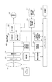
高輝度被写体領域検知部404は、高輝度被写体検知部104から出力された検知結果に基づいて、高輝度被写体が画像中のどの位置にどの大きさで存在しているかを検出する。そして、領域検出した後、高輝度被写体の存在している位置と大きさをシステムコントローラ105に通知する。
Based on the detection result output from the high-brightness
駆動量算出部405は、高輝度被写体検知部104で高輝度被写体を検知した時、システムコントローラ105に保存されている高輝度被写体の領域が通知される。その後、駆動量算出部405は、高輝度被写体領域と動作させる光学系・撮像素子の情報を基に、駆動量を算出する。算出された駆動量を駆動制御部106に入力し、駆動制御部106から駆動部107へと指示を出す。
When the high-brightness
また、駆動量算出部405からの出力は、補正係数算出部406にも入力される。補正係数は、システムコントローラ105から、駆動した光学系(101、102)または撮像素子103の情報と、駆動量算出部405から入力された駆動量を基に、あらかじめ設定してある補正係数記憶部407から対応した補正係数を読み込む。
The output from the drive
画像処理部400は、入力された画像にガンマ補正やカラーバランス調整など所定の処理を行う。また、その処理の中には、輝度補正401、ボケ補正402、幾何補正403のうちいずれか一つ以上の補正モジュールが含まれる。また、各補正モジュールに対して実行の有無やパラメータ設定は、システムコントローラ105又は、補正係数算出部406から制御される。
The
また、本実施例では、撮像光学部の撮像方向をパン方向又はチルト方向に回転させるパン・チルト部408を有している。そして、パン・チルト部408が駆動することで、撮像法を変更中の場合には、駆動デバイスを光軸直行面に対して水平(初期状態)に戻す。それによって、画角が変化した時に補正画像を基に光学系(101、102)または撮像素子の傾きを決定することを防止することができる。
In the present embodiment, a pan /
次に、図6のフローチャートを参照して、本実施例における、システムコントローラ105の動作処理について説明を行う。なお、第1の実施例における、図2と同一の符号を振ったステップは、第1の実施例で説明したものと同様であるので、ここでは必要なフローのみ説明し、残りは省略する。
Next, operation processing of the
ステップS501において、システムコントローラ105は、高輝度被写体を検知した後、高輝度被写体領域検知部404において、高輝度被写体の領域を検知する。より具体的には、高輝度被写体の画面内の位置及び面積を検知する。そして処理をステップS502に進める。
In step S <b> 501, the
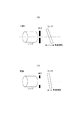
ステップS502において、システムコントローラ105は、高輝度被写体領域検知部404の検知結果に含まれる高輝度被写体の画像内における位置と面積に基づいて、駆動量算出部405に設定するための駆動量及び駆動方向を算出する。その算出について、図7を参照して説明を行う。
In step S <b> 502, the
図7は、高輝度被写体領域を検知した時に、駆動デバイスは撮像素子、駆動方向は傾き方向とした場合の例を示す図である。 FIG. 7 is a diagram illustrating an example in which when a high-luminance subject area is detected, the drive device is an image sensor and the drive direction is an inclination direction.
まず、図7(a)は、撮像画像の中で高輝度被写体領域を検知した場面を示している。図示したような位置に高輝度被写体領域を検知した場合に、この高輝度被写体からの光線を模式的に図7(b)に示した。このような位置関係に高輝度被写体が存在する場合、撮像素子からの反射光が再びレンズに反射し、撮像素子への結像される可能性がある。そのため、撮像素子からの反射光がレンズに入らないような光学的な位置関係にするために、撮像素子を傾ける。しかし、傾けることによってフォーカス状態が変化するため、傾き量はできるだけ小さくする必要がある。本発明に係る撮像装置1000においては、より傾ける角度が小さくなるように駆動方向と駆動量を算出する。図7の高輝度被写体一においては、図7(c)に示す方向に撮像素子103を傾けた方が、傾き量は小さいので、そちらに駆動させている。駆動方向は、画面内の位置とレンズ101から撮像素子103に入射する光線角度の対応をメモリー等に保存しておき、それからシステムコントローラ105が算出する。本処理の終了後、ステップS503に処理を進める。
First, FIG. 7A shows a scene in which a high brightness subject area is detected in a captured image. When a high-luminance subject area is detected at the position shown in the figure, the light beam from the high-luminance subject is schematically shown in FIG. When a high-luminance subject exists in such a positional relationship, there is a possibility that the reflected light from the image sensor is reflected again by the lens and imaged on the image sensor. For this reason, the image sensor is tilted in order to achieve an optical positional relationship in which reflected light from the image sensor does not enter the lens. However, since the focus state changes by tilting, it is necessary to make the tilt amount as small as possible. In the
なお、本図面においては、簡単のため2次元で描写しているが、実際は3次元的に駆動方向と駆動量が決まるものとする。また、図7では撮像素子を傾ける例を示したが、本実施例においては他の光学系(101、102)を制御する、もしくはxyz方向に駆動させる等、ゴーストを抑制する効果を得られる方法であればよい。 In the drawing, for the sake of simplicity, the drawing is illustrated in two dimensions, but in reality, the driving direction and the driving amount are determined three-dimensionally. 7 shows an example in which the image sensor is tilted, but in this embodiment, a method for obtaining an effect of suppressing ghosts by controlling other optical systems (101, 102) or driving in the xyz direction. If it is.
ステップS503において、システムコントローラ105は、光学系(101、102)または撮像素子の駆動デバイスを、ステップS502における駆動量を基に駆動制御部106によって制御する。そして、処理をステップS204に進める。
In step S503, the
ステップs204において、システムコントローラ105は、傾き量が閾値以下になるかどうかを判定する。この際、閾値を決めるのは、第1の実施例において示したように、あらかじめ設定する方法もある。ここでは、他の方法の例として、撮像素子の傾き量の閾値設定について図8を用いて説明する。
In step s204, the
図8(a)は、絞りが小絞りの時の焦点深度を示しており、図8(b)は絞りが開放の時の焦点深度を示している。ここで、焦点深度とはピント位置がずれた際に発生するボケの許容可能な範囲である。図8(a)のように、絞りが小絞り状態の時には、焦点深度が深くなる。そのため、撮像素子の傾き幅大きく取ってもボケが目立たないため、傾き量の閾値を大きく設定することが可能となる。一方、絞りが開放の時には、焦点深度が浅くなる。そのため、撮像素子の傾き量の閾値を小さく設定して、ボケ自体をあまり発生しないようにする。なお、駆動量が本実施例で示した方法で設定された閾値以上になった場合は、ステップs205の際にも、同様に駆動量を閾値までに制限されることとなる。 FIG. 8A shows the depth of focus when the aperture is a small aperture, and FIG. 8B shows the depth of focus when the aperture is open. Here, the depth of focus is an allowable range of blurring that occurs when the focus position shifts. As shown in FIG. 8A, when the aperture is in the small aperture state, the depth of focus becomes deeper. For this reason, even if the inclination width of the image sensor is large, blurring is not noticeable, and thus it is possible to set a large threshold value for the inclination amount. On the other hand, when the aperture is full, the depth of focus becomes shallow. Therefore, the threshold value of the tilt amount of the image sensor is set to be small so that the blur itself does not occur so much. If the drive amount is equal to or greater than the threshold value set by the method shown in this embodiment, the drive amount is similarly limited to the threshold value in step s205.
ステップs504では、システムコントローラ105は、ステップs502において算出された駆動デバイスの駆動量を基に、補正係数算出部406が補正係数記憶部407より対応した補正係数を取得する。そして、その値または補正係数算出部406で補間した値を補正係数として算出する。そして、算出された補正係数を基に、画像処理部400で輝度補正401、ボケ補正402、幾何補正313のうちいずれか一つ以上の補正を適用する。
In step s504, the
上記のとおり本第2の実施例によれば、高輝度被写体の領域を検知し、光学系(101、102)または撮像素子103の方向と駆動量をより細かに制御して、駆動量を抑えることができる。また、駆動量から補正値を正確に算出することで、ゴーストを抑制しつつ、画像劣化のより抑えられた画像を実現できる。
As described above, according to the second embodiment, a region of a high-luminance object is detected, and the direction and drive amount of the optical system (101, 102) or the
(実施例3)
以下、図9を参照して、本発明の第3の実施例による、撮像装置の構成について説明する。なお、第2の実施例における、図4と同一の符号を振った装置は、第2の実施例で説明したものと同様であるので、ここでは必要な装置のみ説明し、残りは省略する。
(Example 3)
The configuration of the imaging apparatus according to the third embodiment of the present invention will be described below with reference to FIG. The apparatus having the same reference numerals as those in FIG. 4 in the second embodiment is the same as that described in the second embodiment, so only the necessary apparatus will be described here and the rest will be omitted.
モード制御部801は、フォーカス優先モード及びゴースト抑制優先モードの二つのモードの切り替えを所定の条件に応じて制御する。モード制御部801の制御結果はシステムコントローラ105に反映され、各ブロックの制御に用いられる。
The
モード判定部802は、現在のモードがどちらのモードかを判定する。これによって、モード制御部801が制御している状況を適切なタイミングで判定することができる。また、モード判定部802の判定結果はシステムコントローラ105に入力される。
The
ゴースト抑制レベル設定部803は、画像を任意の領域に分割し、それぞれの領域にゴースト抑制レベルを判定する。ゴーストレベル抑制の判定は、各領域の輝度又は色差情報から求められるゴースト量を判定する。
A ghost suppression
レベル別駆動範囲算出部804は、高輝度被写体領域検知部404で検知した高輝度被写体がどの領域にいるかの情報を、システムコントローラ105を介して取得する。その取得した情報を基に、画角内にあらかじめ設定されたゴースト抑制レベルに従った駆動量の最大値を算出する。駆動量の最大値を、システムコントローラ105を介して、駆動制御部106へと出力する。
The level-specific drive
次に、図10のフローチャートを参照して、本実施例における、システムコントローラ105の動作処理について説明を行う。なお、第3の実施例における、図2及び図5と同一の符号を振った装置は、第1の実施例または第2の実施例で説明したものと同様であるので、ここでは必要なフローのみ説明し、残りは省略する。
Next, operation processing of the
ステップs901において、システムコントローラ105は、ユーザーの操作などでモード制御部801が設定した、現在のモードをモード判定部802が判定する。モードは、ゴースト抑制優先モードおよびフォーカス優先モードの二つのモードがある。ゴースト抑制優先モードは、ゴーストの発生抑制を行うことを優先し、光学系(101、102)または撮像素子103を駆動させるモードである。また、フォーカス優先モードは、フォーカス(ピント制御)を優先させ、光学系(101、102)または撮像素子103を駆動させないモードである。
In step s901, in the
そのために、ステップs901において、システムコントローラ105は、現状のモードを判定し、フォーカス優先モードであれば、処理を終了する。一方で、ゴースト抑制優先モードであれば、次のステップに処理を進める。
Therefore, in step s901, the
その後、ステップs202及びステップs501において、システムコントローラ105は、高輝度被写体の領域を検知する。そして、検知した領域がステップs902で処理され、閾値が設定される。その詳細な動作について、図11を参照して説明する。
Thereafter, in step s202 and step s501, the
図11は、最外側の実線に囲まれた部分は、撮影された画像の領域を示している。また、その一つ内側の破線の長方形の内部は、ゴースト抑制小の領域を示している。最後に、再内側の破線の長方形の内部は、ゴースト抑制大の領域を示している。図11で示したそれぞれの領域では、光学系(101、102)または撮像素子103を駆動制御部で動作させる駆動量の上限値が定められている。これらのゴースト抑制領域と駆動量の上限値は、ユーザーからの要求などによって、ゴースト抑制レベル制御部803において設定される。
In FIG. 11, a portion surrounded by the outermost solid line indicates a captured image area. In addition, the inside of the rectangle indicated by a broken line on the inner side shows a region where the ghost suppression is small. Finally, the inside of the dashed inner rectangle indicates a region where ghost suppression is large. In each region shown in FIG. 11, an upper limit value of the drive amount for operating the optical system (101, 102) or the
ステップs204において、システムコントローラ105は、駆動量が閾値以下かどうか判定しているが、ここの閾値は、ステップs902で算出されたゴースト抑制レベルによって定まっている。より詳細には、画面の周辺部でゴースト等が発生したとしても、画像に対する影響は少なく、逆に抑制動作による弊害(フォーカスずれ等)による影響が大きい場合がある。一方で、画面中心部は注目被写体が存在する頻度が高く、ゴースト等が発生した場合は高い確率で画像に対して影響を与える。そのため、ステップs202及びステップs501において、検知した領域が画面の中心部か、又は周辺部かを判定することで、適切なゴースト抑制が可能となる。その後の処理は、第2の実施例で説明したとおりである。
In step s204, the
上記のとおり、本第3の実施例によれば、高輝度被写体の領域の場所により、光学系(101、102)または撮像素子103の駆動量の上限値を決めている。そのため、画角内の重要な被写体では、ゴーストによる視認性の低下をできる限り抑え、あまり重要でない被写体の場合は、重要な被写体に対しての、誤補正や過補正による画質の劣化を抑えることができる。
As described above, according to the third embodiment, the upper limit value of the driving amount of the optical system (101, 102) or the
以上、本発明の好ましい実施例について説明したが、本発明はこれらの実施例に限定されず、その要旨の範囲内で種々の変形及び変更が可能である。 As mentioned above, although the preferable Example of this invention was described, this invention is not limited to these Examples, A various deformation | transformation and change are possible within the range of the summary.
101 レンズ
102 光学フィルタ
103 撮像素子
104 高輝度被写体検知部
105 システムコントローラ
110 通信部
1000 撮像装置
2000 クライアント装置
3000 ネットワーク
DESCRIPTION OF
Claims (10)
前記撮像光学部によって結像される被写体像を画像データに変換する撮像手段と、
前記画像データにおいて高輝度領域を検知する検知手段と、
前記撮像光学部及び前記撮像手段の少なくとも一つを駆動する駆動手段と、
前記駆動手段を前記検知手段の検知結果に基づいて制御する駆動制御手段を備え、
前記駆動制御手段は前記駆動手段による駆動量を所定の閾値以下となるように制御することを特徴とする撮像装置。 An imaging apparatus having an imaging optical unit,
Imaging means for converting a subject image formed by the imaging optical unit into image data;
Detecting means for detecting a high-luminance region in the image data;
Driving means for driving at least one of the imaging optical unit and the imaging means;
Drive control means for controlling the drive means based on the detection result of the detection means,
The image pickup apparatus, wherein the drive control unit controls the drive amount by the drive unit to be a predetermined threshold value or less.
前記駆動手段による駆動量を基に補正係数記憶手段から補正係数を取得する取得手段と、
をさらに備えることを特徴とした請求項2に記載の撮像装置。 Storage means for storing correction coefficients used in the correction means in advance;
Obtaining means for obtaining a correction coefficient from a correction coefficient storage means based on a driving amount by the driving means;
The imaging apparatus according to claim 2, further comprising:
前記領域検出手段が検出した領域を基に駆動量を算出する算出手段を更に備え、
前記駆動制御手段は前記算出手段が算出した駆動量を基に前記駆動手段を駆動量することを特徴とした請求項1に記載の撮像装置。 Area detecting means for detecting the area of the high-luminance subject detected by the detecting means;
A calculation unit that calculates a driving amount based on the region detected by the region detection unit;
The imaging apparatus according to claim 1, wherein the drive control unit drives the drive unit based on the drive amount calculated by the calculation unit.
前記変更手段が変更中の場合は、前記駆動手段による駆動量を初期状態にすることを特徴とする請求項1記載の撮像装置。 A changing unit that changes an imaging direction of the imaging optical unit to a pan direction or a tilt direction;
The imaging apparatus according to claim 1, wherein when the changing unit is changing, the driving amount by the driving unit is set to an initial state.
前記駆動制御手段は前記判定手段の判定結果に基づいて前記駆動手段を制御することを特徴とする請求項1に記載の撮像装置。 A determination means for determining a mode for the drive control means to control the drive means;
The imaging apparatus according to claim 1, wherein the drive control unit controls the drive unit based on a determination result of the determination unit.
前記駆動制御手段は前記検知手段の検知結果に基づいて前記駆動手段を制御することを特徴とする請求項1に記載の撮像装置。 The detecting means detects at least a position and a luminance value of a high luminance region in the image data;
The imaging apparatus according to claim 1, wherein the drive control unit controls the drive unit based on a detection result of the detection unit.
Priority Applications (1)
| Application Number | Priority Date | Filing Date | Title |
|---|---|---|---|
| JP2015117039A JP6590539B2 (en) | 2015-06-09 | 2015-06-09 | Imaging device |
Applications Claiming Priority (1)
| Application Number | Priority Date | Filing Date | Title |
|---|---|---|---|
| JP2015117039A JP6590539B2 (en) | 2015-06-09 | 2015-06-09 | Imaging device |
Publications (2)
| Publication Number | Publication Date |
|---|---|
| JP2017005481A true JP2017005481A (en) | 2017-01-05 |
| JP6590539B2 JP6590539B2 (en) | 2019-10-16 |
Family
ID=57754483
Family Applications (1)
| Application Number | Title | Priority Date | Filing Date |
|---|---|---|---|
| JP2015117039A Active JP6590539B2 (en) | 2015-06-09 | 2015-06-09 | Imaging device |
Country Status (1)
| Country | Link |
|---|---|
| JP (1) | JP6590539B2 (en) |
Cited By (1)
| Publication number | Priority date | Publication date | Assignee | Title |
|---|---|---|---|---|
| JP2020106630A (en) * | 2018-12-27 | 2020-07-09 | キヤノン株式会社 | Control device, imaging apparatus and program |
Citations (6)
| Publication number | Priority date | Publication date | Assignee | Title |
|---|---|---|---|---|
| JP2001275039A (en) * | 2000-03-28 | 2001-10-05 | Matsushita Electric Ind Co Ltd | Video camera |
| JP2004077711A (en) * | 2002-08-15 | 2004-03-11 | Ricoh Co Ltd | Camera with camera shake correcting function |
| JP2009116174A (en) * | 2007-11-08 | 2009-05-28 | Olympus Corp | Ghost reducing device and electronic camera provided therewith |
| JP2012063727A (en) * | 2010-09-17 | 2012-03-29 | Canon Inc | Image pickup apparatus |
| US20130250169A1 (en) * | 2012-03-21 | 2013-09-26 | Lg Innotek Co., Ltd. | Camera module |
| WO2014192152A1 (en) * | 2013-05-31 | 2014-12-04 | 株式会社ニコン | Electronic device and control program |
-
2015
- 2015-06-09 JP JP2015117039A patent/JP6590539B2/en active Active
Patent Citations (6)
| Publication number | Priority date | Publication date | Assignee | Title |
|---|---|---|---|---|
| JP2001275039A (en) * | 2000-03-28 | 2001-10-05 | Matsushita Electric Ind Co Ltd | Video camera |
| JP2004077711A (en) * | 2002-08-15 | 2004-03-11 | Ricoh Co Ltd | Camera with camera shake correcting function |
| JP2009116174A (en) * | 2007-11-08 | 2009-05-28 | Olympus Corp | Ghost reducing device and electronic camera provided therewith |
| JP2012063727A (en) * | 2010-09-17 | 2012-03-29 | Canon Inc | Image pickup apparatus |
| US20130250169A1 (en) * | 2012-03-21 | 2013-09-26 | Lg Innotek Co., Ltd. | Camera module |
| WO2014192152A1 (en) * | 2013-05-31 | 2014-12-04 | 株式会社ニコン | Electronic device and control program |
Cited By (2)
| Publication number | Priority date | Publication date | Assignee | Title |
|---|---|---|---|---|
| JP2020106630A (en) * | 2018-12-27 | 2020-07-09 | キヤノン株式会社 | Control device, imaging apparatus and program |
| JP7262997B2 (en) | 2018-12-27 | 2023-04-24 | キヤノン株式会社 | Control device, imaging device, and program |
Also Published As
| Publication number | Publication date |
|---|---|
| JP6590539B2 (en) | 2019-10-16 |
Similar Documents
| Publication | Publication Date | Title |
|---|---|---|
| JP6506517B2 (en) | Image processing apparatus, control method therefor, and imaging apparatus | |
| US10694109B2 (en) | Imaging apparatus | |
| US20130147976A1 (en) | Image capturing apparatus | |
| JP6594524B2 (en) | Imaging apparatus, operating method, image processing apparatus, and image processing method | |
| US11415773B2 (en) | Apparatus and lens apparatus | |
| JP2008160300A (en) | Image processor, and imaging apparatus | |
| US8264550B2 (en) | Shake correction apparatus, image pickup apparatus, and method for controlling shake correction apparatus | |
| US20150049216A1 (en) | Image capturing apparatus | |
| JP2019145958A (en) | Imaging apparatus, control method of the same, and program | |
| JP6070283B2 (en) | Imaging apparatus, exposure control method, and program | |
| JP5436116B2 (en) | Image processing apparatus, imaging apparatus, and control method | |
| JP2016080918A (en) | Image shake correction device and control method therefor | |
| JP6289243B2 (en) | Image blur correction apparatus, control method therefor, program, and storage medium | |
| JP6590539B2 (en) | Imaging device | |
| JP2020160163A5 (en) | ||
| US10536642B2 (en) | Image stabilization apparatus that corrects for image blurring, control method therefor, image pickup apparatus, and storage medium | |
| JP6395513B2 (en) | Imaging apparatus, control method therefor, program, and storage medium | |
| US20240080562A1 (en) | Image blur correction control apparatus and control method | |
| JP7023678B2 (en) | Image pickup device, control method of image pickup device, and program | |
| US20230131656A1 (en) | Image capturing apparatus and method for controlling the same, and non-transitory computer-readable storage medium | |
| JP2019145956A (en) | Imaging apparatus, control method of the same, and program | |
| JP7336754B2 (en) | Imaging device | |
| JP2022158303A (en) | Imaging apparatus | |
| WO2020012960A1 (en) | Imaging device | |
| JP2020056854A (en) | Diaphragm control means during vibration-proof in imaging system |
Legal Events
| Date | Code | Title | Description |
|---|---|---|---|
| A621 | Written request for application examination |
Free format text: JAPANESE INTERMEDIATE CODE: A621 Effective date: 20180420 |
|
| A131 | Notification of reasons for refusal |
Free format text: JAPANESE INTERMEDIATE CODE: A131 Effective date: 20190205 |
|
| A521 | Request for written amendment filed |
Free format text: JAPANESE INTERMEDIATE CODE: A523 Effective date: 20190405 |
|
| A131 | Notification of reasons for refusal |
Free format text: JAPANESE INTERMEDIATE CODE: A131 Effective date: 20190528 |
|
| A521 | Request for written amendment filed |
Free format text: JAPANESE INTERMEDIATE CODE: A523 Effective date: 20190720 |
|
| TRDD | Decision of grant or rejection written | ||
| A01 | Written decision to grant a patent or to grant a registration (utility model) |
Free format text: JAPANESE INTERMEDIATE CODE: A01 Effective date: 20190820 |
|
| A61 | First payment of annual fees (during grant procedure) |
Free format text: JAPANESE INTERMEDIATE CODE: A61 Effective date: 20190917 |
|
| R151 | Written notification of patent or utility model registration |
Ref document number: 6590539 Country of ref document: JP Free format text: JAPANESE INTERMEDIATE CODE: R151 |